centrifugal pumps -...
TRANSCRIPT
1
CENTRIFUGAL PUMPSe-notes: Dr.N.BalasubramanyaProfessor, Department of Civil Engineering
M.S.Ramaiah Institute of Technology, Bangalore-560054
A pump is a hydraulic machine which converts mechanical energy into hydraulic energyor pressure energy.A centrifugal pump is also known as a Rotodynamic pump or dynamic pressure pump. Itworks on the principle of centrifugal force. In this type of pump the liquid is subjected towhirling motion by the rotating impeller which is made of a number of backward curvedvanes. The liquid enters this impeller at its center or the eye and gets discharged into thecasing enclosing the outer edge of the impeller. The rise in the pressure head at anypoint/outlet of the impeller is Proportional to the square of the tangential velocity of the
liquid at that point )2g
2uα(i.e, . Hence at the outlet of the impeller where the radius is
more the rise In pressure head will be more and the liquid will be discharged at the outletwith a high pressure head. Due to this high pressure head, the liquid can be lifted to ahigher level. Generally centrifugal pumps are made of the radial flow type only. Butthere are also axial flow or propeller pumps which are particularly adopted for low heads.Advantages of centrifugal pumps:-
1. Its initial cost is low2. Efficiency is high.
3. Discharge is uniform and continuous4. Installation and maintenance is easy.5. It can run at high speeds,without the risk of separation of flow
Classification of centrifugal pumpsCentrifugal pumps may be classifiedInto the following types1.According to casing design
a) Volute pump b) diffuser or turbine pump2. According to number of impellers
a) Single stage pump b) multistage or multi impeller pump3. According to number of entrancesto the impeller:
a) Single suction pump (FOR FIGURES DOWNLOAD PRESENTATION)b) Double suction pump
4. According to disposition of shafta) Vertical shaft pumpb) Horizontal shaft pump
5. According to liquid handleda) Semi open impellerb) Open impeller pump
2
6.According to specific speeda) Low specific speed or radial flow impeller pumpb) Shrouded impellerc) Medium specific speed or mixed flow impeller pump
c) High specific speed or axial flow type or propeller pump.7. According to head (H)
• Low head if H<15m• Medium head if 15<H<40m• High head if H>40m
In the case of a volute pump a spiral casing is provided aroundthe impeller. The water which leaves the vanes is directed to flow in the volute chambercircumferentially. The area of the volute chamber gradually increases in the directionflow. Thereby the velocity reduces and hence the pressure increases. As the water reachesthe delivery pipe a considerable part of kinetic energy is converted into pressure energy.However, the eddies are not completely avoided , therefore some loss of energy takesplace due to the continually increasing quantity of water through the volute chamber.In the case of a diffuser pump the guide wheel containing a series of guide vanes ordiffuser is the additional component. The diffuser blades which provides graduallyenlarging passages surround the impeller periphery. They serve to augment the process ofpressure built up that is normally achieved in the volute casing. Diffuser pumps are alsocalled turbine pumps in view of their resemblance to a reaction turbine.Multistage pumps and vertical shaft deep-well pumps fall under this category.Centrifugal pumps can normally develop pressures upto 1000kpa (100m). If higherpressures are required there are three options.a) Increase of impeller diameter.b)Increase of Rpm. c)Use of two or more impellers in series.The pump looks clumsy in option (a). The impeller material is heavily stressed in option(b) The third choice is the best and is generally adopted, the impellers which are usuallyof the same size are mounted on the same shaft. The unit is called a multistage pump. Itdischarges the same quantity of fluid as a single stage pump but the head developed ishigh. There are centrifugal pumps upto 54 stages. However, generally not more than 10stages are required. In the case of the double suction impeller, two impellers are set backto back. The two suction eyes together reduce the intake. The two suction eyes togetherreduce the intake velocity reduce the risk of cavitations. Mixed flow type double suctionaxial flow pumps besides are capable of developing higher heads. For convenience ofoperation and maintenance, horizontal shaft settings are the preferred setups forcentrifugal pumps. The exceptions are deep-well turbine pumps and axial flow pumps,these have vertical shafts. Restricted space conditions usually require a vertical shaftsetting. Centrifugal impellers usually have vanes fitted between the shroudes or plate.
The crown plate has the suction eye and the base plate is mounted on a sleeve whichis keyed to the shaft. An impeller without the crown plate is called the non-clog or semi-open impeller. In an open impeller both crown plate and the base plate are absent.Only clear liquids, can be safely pumped by a shrouded impeller pump. The semi-openimpeller is useful for pumping liquids containing suspended solids, such as sewage,molasses or paper pulp. The open-vane impeller pump is employed for dredgingoperations in harbours and rivers. Shrouded and semi open impellers may be made of cast
3
iron Or cast steel. Open vane impellers are usually made of forged steel. If the liquidpumped are corrosive, brass, bronze or gun metal are the best materials for making theimpellers.A radial flow impeller has small specific speeds (300 to 1000) & is suitable fordischarging relatively small quantities of flow against high heads. The direction of flowat exit of the impeller is radial. The mixed flow type of impellers has a high specificspeed (2500 to 5000), has large inlet diameter D and impeller width B to handle relativelylarge discharges against medium heads. The axial flow type or propeller impellers havethe highest speed range (5000 to 10,000). They are capable of pumping large dischargesagainst small heads. The specific speed of radial pump will be 10<Ns<80, Axial pump100<Ns<450, Mixed flow pump 80<Ns<160.Components of a centrifugal pumpThe main components of a centrifugal pump are:i) Impeller ii) Casing iii) Suction pipe iv) Foot valve with strainer, v) Delivery pipe vi)Delivery valve.Impeller is the rotating component of the pump. It is made up of a series of curvedvanes. The impeller is mounted on the shaft connecting an electric motor.Casing is an air tight chamber surrounding the impeller. The shape of the casing isdesigned in such a way that the kinetic energy of the impeller is gradually changed topotential energy. This is achieved by gradually increasing the area of cross section in thedirection of flow.Suction pipe It is the pipe connecting the pump to the sump, from where the liquid has tobe lifted up.Foot valve with strainer the foot valve is a non-return valve which permits the flow ofthe liquid from the sump towards the pump. In other words the foot valve opens only inthe upward direction.The strainer is a mesh surrounding the valve, it prevents the entry of debris and silt intothe pump.Delivery pipe is a pipe connected to the pump to the overhead tank.Delivery valve is a valve which can regulate the flow of liquid from the pump.Priming of a centrifugal pumpPriming is the process of filling the suction pipe, casing of the pump and the deliverypipe upto the delivery valve with the liquid to be pumped.
If priming is not done the pump cannot deliver the liquid due to the fact that thehead generated by the Impeller will be in terms of meters of air which will be very small(because specific weight of air is very much smaller than that of water).Priming of a centrifugal pump can be done by any one of the following methods:
i) Priming with suction/vacuum pump.ii) Priming with a jet pump.
iii) Priming with separator.iv) Automatic or self priming.
Heads on a centrifugal pump:Suction head (hs): it is the vertical distance between the liquid levelin the sump and the centre line of the pump. It is expressed as meters.Delivery head (hd): It is the vertical distance between the centre line of the pump andthe liquid level in the overhead tank or the supply point. It is expressed in meters.

4
Static head (Hs): It is the vertical difference between the liquid levelsIn the overhead tank and the sump, when the pump is not working. It is expressed asmeters.Therefore, HS= (hs+ hd)Friction head (hf): It is the sum of the head loss due to the friction in the suction anddelivery pipes. The friction loss in both the pipes is calculated using the Darcy’sequation, hf=(fLV2/2gD).Total head (H): It is the sum of the static head Hs, friction head (hf) and the velocityhead in the delivery pipe (Vd 2/2g). Where, Vd=velocity in the delivery pipe.
)1(
2gVdhhhH
2
fdsm
Manometric head(Hm): It is the total head developed by the pump. This head is slightlyless than the head generated by the impeller due to some losses in the pump
2gVd
2gVsHH
22
m
Working of a centrifugal pump:A centrifugal pump works on the principal that when a certain mass of fluid is rotated byan external source, it is thrown away from the central axis of rotation and a centrifugalhead is impressed which enables it to rise to a higher level.Working operation of a centrifugal pump is explained in the following steps.
1) Close the delivery valve and prime the pump.2) Start the motor connected to the pump shaft, this causes an increase in the
impeller pressure.3) Open the delivery valve gradually, so that the liquid starts flowing into the deliver
pipe.4) A partial vacuum is created at the eye of the centrifugal action, the liquid rushed
from the sump to the pump due to pressure difference at the two ends fo the suction pipe.5) As the impeller continues to run, move & more liquid is made available to the
pump at its eye. Therefore impeller increases the energy of the liquid and delivers it tothe reservoir.
6) While stopping the pump, the delivery valve should be closed first, otherwise theremay be back flow from the reservoir.It may be noted that a uniform velocity of flow is maintained in the delivery pipe. This isdue to the special design of the casing. As the flow proceeds from the tongue of thecasing to the delivery pipe, the area of the casing increases. There is a correspondingchange in the quantity of the liquid from the impeller. Thus a uniform flow occurs in thedelivery pipe.Operation difficulties in centrifugal pumps
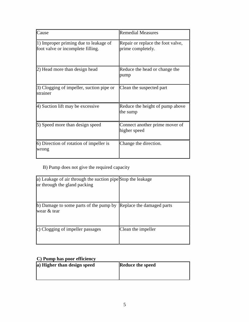
a) Pump fails to pump the fluid.
5
Cause Remedial Measures
1) Improper priming due to leakage offoot valve or incomplete filling.
Repair or replace the foot valve,prime completely.
2) Head more than design head Reduce the head or change thepump
3) Clogging of impeller, suction pipe orstrainer
Clean the suspected part
4) Suction lift may be excessive Reduce the height of pump abovethe sump
5) Speed more than design speed Connect another prime mover ofhigher speed
6) Direction of rotation of impeller iswrong
Change the direction.
B) Pump does not give the required capacity
a) Leakage of air through the suction pipeor through the gland packing
Stop the leakage
b) Damage to some parts of the pump bywear & tear
Replace the damaged parts
c) Clogging of impeller passages Clean the impeller
C) Pump has poor efficiencya) Higher than design speed Reduce the speed
6
b) Low head & higher discharge Reduce the discharge
c) Impeller touching, the casing orimproper alignment of shaft
Carryout the necessary repair.
D) Pump stops workinga) Air entry into suction pipe Stop the pump, plug the leakage,
reprime and start
b) Suction lift is high Reduce the suction lift.
Efficiencies of centrifugal pumpManometric efficiency (η): it is the ratio of the manometric head to the head actually
generated by the impeller
222 uVwgHm
u2/gVwHm
nmano
Mechanical efficiency(η mech): It is the ratio of the impeller power to the power of the
motor or the prime mover.
powermotorpowerimpellermechn
Overall efficiency(ηo): It is the ratio of the work done by the pump in lifting wateragainst gravity and friction in the pipes to the energy supplied by the motor.
motorormoverprimetheofpowerfrictiongravityagainstdoneworkno
Velocity Triangles of a Centrifugal PumpFigure shows the inlet and outlet velocity triangles for a centrifugal pump.It may be notedthat the inlet velocity triangle is radial,(velocity of whirl is zero at inlet or VW1 =0Depending on the geometry of the blade at outlet it can be:Forward:if the blade angle<900 ,Radial if Φ=900 , c) Backward if 090
Work done by the impeller of a centrifugal pump:Figure shows the velocity triangles at the inlet and outlet tips of a vane fixed to theimpeller.Let N=speed of the impeller in RPM
D= Diameter of the impeller at inlet
7
D=Diameter of the impeller at outletU1 = Tangential velocity of the impeller at inlet N/60πD1
U2= tangential velocity of the impeller at outlet N/60πD2
V1=absolute velocity of the liquid at inletV2= absolute velocity of the liquid at outlet.
21 Vf&Vf are the velocities of flow at inlet and outlet.
21 Vr&Vr Relative velocities at inlet and outlet
2Vw whirl velocity at outlet
angle made by 1V with respect to the motion of the vane blade angle at inlet
= blade angle at outletFor a series of curved vanes the force exerted can be determined using the impulse
momentum equation Work=force x distance.similarly the work done/sec/unit weight of the liquid striking the
vane= )uVwu(Vwg1
1122
But for a centrifugal pump 0Vω1
Work done/sec/unit weightg
uVw 22
And the work done/sec )4(22uVwgQ
Where Q=volume of liquid flowing per second = Area x velocity offlow )5( 222 VfBπDQIn eq (5), 2B is the width of the impeller at the outlet.
Design factors of centrifugal pumps:a) Rim diameter 2D
Rim velocity or impeller velocity60
NπDu 22 2gHmKu
Rim diameter Hm2gKuπN60D2 = HmK
N85
u
Where N= speed in RPM Hm= manometric head, m
ratiospeed2gHm/UK 2u Value of varies from 0.95 to 1.8 depending on the specific speed.b) Pipeline diameter:The diameter of section and delivery pipes are designed to give velocities not exceeding1.5 to 3 m/s on section and delivery sides.c) Discharge (Q): the discharge or capacity of a centrifugal pump is given byWhere k =factor which accounts the reduction in flow area due toTo thickness of impeller vanes,D2 =Rim diameter,B2 =Rim width,

8
Vf2=Constant velocity of flow through the impeller. Generally k=1 is considered.
PROBLEMS
1.A centrifugal pump running at 800 Rpm is working against a total head of 20.2 m. theexternal diameter of the impeller is 480mm and outlet width 60mm. If the valve angle atoutlet is 40 and manometric efficiency is 70% determinea)Absolute velocity of water leavingb) Flow velocity at outlet The valve.
c) Angle made by the absolute velocity at outlet with the direction of motion at outlet.d) Rate of flow through the pump.
Soln: velocity of valve at outlet60
22
NDu
sm
xx/1.20
60
80048.0
22uVw
gHmnefficiencymanometric mano ,
1.20
2.2081.970.0
2xVw
x , smVw /08.142
From the outlet velocity triangle22
2tanVwu
Vf
smxVf /05.5)08.141.20(40tan 02
Absolute velocity of water leaving the valve 2V is given by
smVwVfV /96.1408.1405.5 2222
222
Angle made by the absolute velocity at outlet with the direction of motion is given by
3586.008.14
05.5tan
2
2 Vw
Vf 07.19
Rate of flow through the pump 05.506.048.0222 xxxVfBDQ sm /3457.0
2. A centrifugal pump impeller having external and internal diameter 480mm and240mm respectively is running at 100 Rpm. The rate of flow through the pump is 0.0576m3/s and velocity of flow is constant and equal to 2.4m/s. the diameter of the section anddelivery pipes are 180mm and 120mm respectively and section and delivery heads are6.2m(abs) and 30.2m(abs) of water respectively. If the power required to drive the pumpis 23.3KW and the outlet vane angle is 45 determine. a) inlet vane angle b) Overallefficiency c) manometric efficiency of the pump
Soln: tangential velocity or impeller velocity at inlet
smxxND
u /56.1260
100024.0
601
1
From the inlet velocity triangle 191.056.12
41.2tan
1
1 u
Vf
)(8.10 0 anglevaneinlet
9
Overall efficiency3.23
05.081.90
xHmx
P
rQHmn )1(02387.00 Hmn
g
V
r
pZ
g
V
r
pZHmbut
22,
211
1
222
2
smx
x
d
QVVwhere
dd /01.5
12.0
0567.044,
222
smx
x
d
QVVwhere
ss /23.2
18.0
0567.044,
222
21 ZZlet i.e pump inlet and outlet are at same level.
)(2.61 absmhr
ps )(2.302 absmh
r
pd
mxx
Hm 03.2581.92
23.22.6
81.92
01.52.30
22
0n , overall efficiency of pump
=0.02387x25.03=0.597=59.7%
Velocity of the impeller at outlet smxxND
u /13.2560
100048.0
602
2
From the outlet velocity triangle22
2tanVwu
Vf
,
2
0
13.25
4.245tan
Vw ,
smVw /73.222
Manometric efficiency %4343.013.2573.22
03.2581.9
22
x
x
uVw
gHmnmano
3. It is required to deliver 0.048m3/s of water to a height of 24m through a 150mmdiameter and 120m long pipe by a centrifugal pump. If the overall Efficiency of thepump is 75% and co efficient of friction f=0.01 for the pipe line. Find the power requiredto drive the pump.
Soln: velocity of water pipe2
4
d
QVVV ds sm
x
x/7.2
15.0
048.042
Overall efficiencyP
rQHmn 0 P
xx 37.27048.081.975.0 , KWP 2.17
4. The impeller of a centrifugal pump is of 300mm diameter and 50mm width at theperiphery and has blades whose tip angle incline backwards 60 from the radius. Thepump deliveries 17m3/min of water and the impeller rotates at 1000Rpm. Assuming that the pump is design to admit radically. calculate
a)Speed and direction of water as it leaves the impeller,b)Torque exerted by the impeller on water c) Shaft power required
10
d) Lift of the pump. Take mechanical=95% and hydraulic efficiency=75%
Soln: tangential velocity of the impeller at the outlet
smxxND
u /71.1560
10003.0
602
2
From continuity equation 222 VfBDQ , smxx
Vf /605.03.0
2833.02
From the outlet velocity triangle22
2tanVwu
Vf
smVf
uVw /24.1260tan
671.15
tan 02
22
Absolute velocity of water at the outlet tip of the impeller
2222
222 24.126 VwVfV )(/63.132 magnitudesmV
01
2
21 5.2624.12
6tantan
Vw
Vf
Torque exerted by the impeller on water
)2
3.024.12(
81.9
2833.081.9)( 22 xx
xRVw
g
rQT mKN52.0
Shaft power (P) impeller or rotor power KWxxNT
45.5460
52.010002
60
2
But, mechanical efficiencypowershaft
powerimpellernmech P
ei45.54
95.0,. KWP 31.57
Lift of the pumpImpeller power=r(Q+q)HWhere r=sp wt of water=9.81 KN/m3H =ideal head=(theoretical head-hyd losses)Q=leakage of water m3/sNeglecting leakages q we have
54.45=9.81x0.2833xHOr h =19.59m
We know, hydraulic efficiencyheadideal
liftorheadActualnh
)( ih HheadxidealnhftActual waterofmx 71.1359.1970.0
5. The following data relate to a centrifugal pump. Diameter of the impeller at inlet &outlet =180mm and 360mm respectively. width of impeller at inlet and outlet=144mm &72mm respectively. rate of flow through the pump=17.28lps. Speed of the impeller =1500 Rpm. Vane angle at outlet=45 water enters the impeller radially at inlet neglectinglosses through the impeller. Find the pressure rise in the impeller.
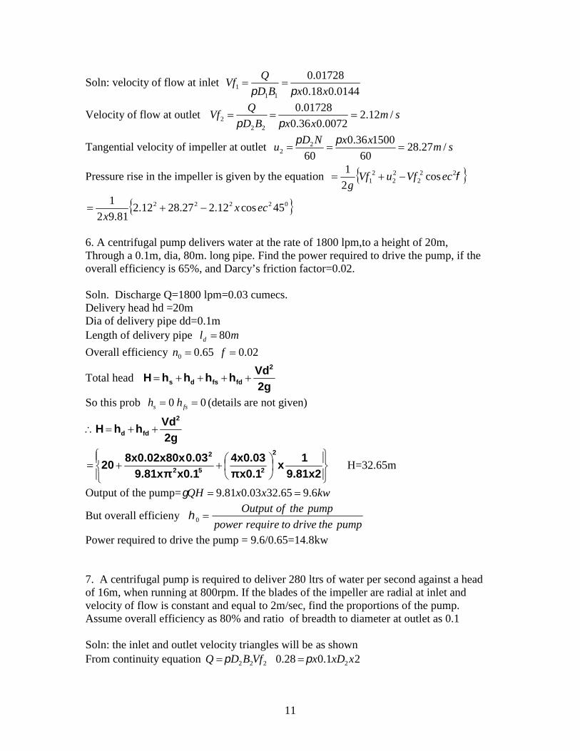
11
Soln: velocity of flow at inlet0144.018.0
01728.0
111 xxBD
QVf
Velocity of flow at outlet smxxBD
QVf /12.2
0072.036.0
01728.0
222
Tangential velocity of impeller at outlet smxxND
u /27.2860
150036.0
602
2
Pressure rise in the impeller is given by the equation 222
22
21 cos
2
1ecVfuVf
g
02222 45cos12.227.2812.281.92
1ecx
x
6. A centrifugal pump delivers water at the rate of 1800 lpm,to a height of 20m,Through a 0.1m, dia, 80m. long pipe. Find the power required to drive the pump, if theoverall efficiency is 65%, and Darcy’s friction factor=0.02.
Soln. Discharge Q=1800 lpm=0.03 cumecs.Delivery head hd =20mDia of delivery pipe dd=0.1mLength of delivery pipe mld 80Overall efficiency 02.065.00 fn
Total head2gVdhhhhH
2
fdfsds
So this prob 00 fss hh (details are not given)
2gVdhhH
2
fdd
9.81x21x
πx0.14x0.03
x0.19.81xπ0.038x0.02x80x20
2
252
2
H=32.65m
Output of the pump= kwxxQH 6.965.3203.081.9
But overall efficienypumpthedrivetorequirepower
pumptheofOutput0
Power required to drive the pump = 9.6/0.65=14.8kw
7. A centrifugal pump is required to deliver 280 ltrs of water per second against a headof 16m, when running at 800rpm. If the blades of the impeller are radial at inlet andvelocity of flow is constant and equal to 2m/sec, find the proportions of the pump.Assume overall efficiency as 80% and ratio of breadth to diameter at outlet as 0.1
Soln: the inlet and outlet velocity triangles will be as shownFrom continuity equation 222 VfBDQ 21.028.0 2xxDx

12
)(67.02 outletatimpellertheofdiametermD cmmxB 7.6067.067.01.02 (Width of the impeller at outlet).
22uVw
gHmnmano
22
1681.98.0
uVw
x
)(2.19622 iuVw smxxND
ubut /1.2860
80067.0
602
2
From eq (i) smVworxVw /99.62.19681.2 22
From the outlet velocity triangle 0947.099.61.28
2tan
22
2
Vwu
Vf
041.5 (Blade angle at outlet) 286.099.6
2tan
2
2 Vw
Vf 016
8. The following data refer to a centrifugal pump static head = 40m, suction height 5m,dia of suction and delivery pipes = 0.1m, loss of head in suction pipe = 2m, loss of headin delivery pipe = 8m, impeller dia at outlet =0.4m, impeller breadth at outlet25mm.blades occupy 10% of the outlet area, speed 1200rpm. Exit angle of blade = 1500with the tangent, Manometric efficiency = 80%, overall efficiency = 70%. Find thepower required to drive the pump and what pressures will be indicated by the gaugesmounted on the suction and delivery sides.
Soln: Outlet vane angle 030150180 Delivery head mhHh ssd 35540 Head on the pump H=40+2+8=50m
From the outlet velocity triangle
22
2tanVwu
Vf
smxxND
uwhere /13.2560
12004.0
60, 2
2
Also from the equation22uVw
gHmnmano sm
x
xVw /4.24
8.013.25
5081.92
0222 30tan)4.2413.25(tan)( VwuVf smVf /422.02
222,arg VfBDKQedisch 422.0025.04.09.0 xxxx sm /30119.0Power given to the liquid P=rQH KWxx 85.5500119.081.9
Power required to drive the pump kwP
36.87.0
85.5
0
Pressure gauge reading on the suction side = hs+hfs waterofm725 Pressure gauge reading on the delivery side = mhh fdd 43835
9. Following data were obtained from a centrifugal pump in a laboratory. Pressure gaugereading on the suction side 15cm of mercury, pressure gauge reading on the delivery side170kN/m2. quantity of water raised by the pump =7.5kN/min. vertical height difference

13
between the gauges =500mm. Total input to the pump = 6.5kw.Find the efficiency of thepump.
Soln: Suction head hs=0.15x13.5=2.04m of waterDelivery head hd=170/9.81=17.34m of water. Head on the pump = (hs+hd+x+Vd2/2g)Since the dia of the delivery pipe is not given, velocity in the delivery pipe is ignored.
mH 88.19)534.1704.2
Discharge from the pump sec/0127.081.9
1
60
5.7 3mx
Output of the pump kwxxQH 48.288.19127.081.9 Efficiency of the pump =2.48/6.5=0.382.=38.2%
10. The internal and external diameters of the impeller of a centrifugal pump are 40cmsand 80cms respectively. The pump is running at 1200rpm. The vane angles at inlet andoutlet are 200 and 300 respectively. Water enters the impeller radially and velocity offlow is constant. Determine the workdone by the impeller per kN of water.
smxxND
uso /13.2560
12004.0
60:ln 1
1
smxxND
u /26.5060
12008.0
601
2
From the inlet velocity triangle1
1tanu
Vf
smVfVf /15.920tan13.25 021
From the outlet velocity triangletanΦ=Vf2/(u2-vw2)=9.15/(50.26-vw2)or , Vw2=34.41m/sWork done/sec=1/g(vw2 u2) =34.41*50.26/9.81=176.3kn-m/s/kn
11. The impeller of a centrifugal pump runs at 90 Rpm and has vaves inclined at 120 tothe direction of motion at exit. If the manometric head is 20m and manometric efficiencyis 75% Vane angles at inlet. Take the velocity of flow as 2.5m/s, throughout and thediameter of the impeller at exit as twice that at inlet.
a) Diameter of the impeller at exit.Soln: From the definition of manometric efficiency 22/ uVwgHmmano
)(6.26175.0
2081.922 i
xuVw
From the outlet velocity triangle 44.160tan
5.2
60tan)(
002
22 Vf
Vwu )44.1( 22 uVw
Substituting the value 2Vw , smuu /9.166.261)44.1( 22 60
22
NDubut
14
smx
xD /59.3
90
9.16602
further smu
u /45.82
9.16
22
1
From the inlet velocity triangle 2959.045.8
5.2tan
1
1 u
Vf
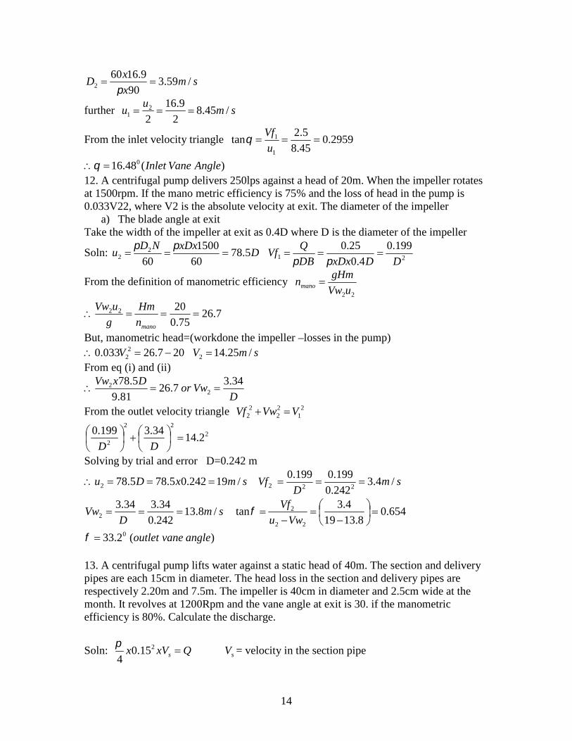
)(48.16 0 AngleVaneInlet12. A centrifugal pump delivers 250lps against a head of 20m. When the impeller rotatesat 1500rpm. If the mano metric efficiency is 75% and the loss of head in the pump is0.033V22, where V2 is the absolute velocity at exit. The diameter of the impeller
a) The blade angle at exitTake the width of the impeller at exit as 0.4D where D is the diameter of the impeller
Soln: DxDxND
u 5.7860
1500
602
2
21
199.0
4.0
25.0
DDxDxDB
QVf
From the definition of manometric efficiency22uVw
gHmnmano
7.2675.0
2022 manon
Hm
g
uVw
But, manometric head=(workdone the impeller –losses in the pump)207.26033.0 2
2 V smV /25.142 From eq (i) and (ii)
DVwor
DxVw 34.37.26
81.9
5.782
2
From the outlet velocity triangle 21
22
22 VVwVf
222
22.14
34.3199.0
DDSolving by trial and error D=0.242 m
smxDu /19242.05.785.782 smD
Vf /4.3242.0
199.0199.0222
smD
Vw /8.13242.0
34.334.32 654.0
8.1319
4.3tan
22
2
Vwu
Vf
)(2.33 0 anglevaneoutlet
13. A centrifugal pump lifts water against a static head of 40m. The section and deliverypipes are each 15cm in diameter. The head loss in the section and delivery pipes arerespectively 2.20m and 7.5m. The impeller is 40cm in diameter and 2.5cm wide at themonth. It revolves at 1200Rpm and the vane angle at exit is 30. if the manometricefficiency is 80%. Calculate the discharge.
Soln: QxVx s 215.0
4
sV = velocity in the section pipe

15
)(6.56 iQVs QVfBD 222 )( QVfxx 2)025.04.0( )(8.312 iiQVf From eq (a) and (b) )(56.02 iiiVVf s
smxxND
unow /1.2560
12004.0
602
2
g
VshfhfhhH dsdsm 2
)(2
g
VsHm 2
5.72.2402
)(2
7.492
ivg
VsHm
22uVw
gHmnmano
1.2530cot56.01.25/
27.4981.98.0 0
2
xxVg
Vsx s 033392 ss VV
)sec(/83.0 pipetiontheinvelocitysmVs
)arg(/30147.06.56
83.0& eDischsmQ
14. A centrifugal pump has a total lift of 15m and is placed 2m above the water level inthe sump. The velocity of water in the delivery pipe is 2m/s. If the radial velocity of flowthrough the wheel is 3m/s and tangent to the vane at exit makes an angle of 60 find (a)the velocity of water at exit (b) the guide vane angle © the pressure at the impeller exit.Neglect friction and other losses.
Soln: total head mg
Vd20.15
62.19
215
215
22
From the outlet velocity triangle0
222 60tan
VfuVw )73.1(
3
322 uu
Hmg
uVwnow 22, 2.15
81.9
)73.1(. 22
uuei smu /12.132
smVw /39.11)73.112.13(2
78.11339.11 2222
222 VfVwV 263.0
39.11
3tan
2
2 Vw
Vf
075.14 (guide vane angle at exist)Applying bernoulli’s equation to points on the sump water surface and impeller exit,
taking datum at the sump level. Hmg
V
r
p 002
2
222
62.19
78.1122.15
22
r
p=6.13m of water (gauge)
15. The axis of a centrifugal pump is 2.5m above the water level in the sump and thestatic lift from the pump centre is 35m. The friction losses in the section and deliveryPipes are of 15cm diameter. The impeller is 30cm diameter and 2cm wide at outlet and itsspeed is 1800 Rpm. The blade angle at exit is 30. calculate the shaft power to be suppliedand the discharge delivered. Take n mano=75% and n o=70%. If the guages are

16
connected to the section and delivery sides of the pump determine the pressure indicatedby these guages.Soln:
smxxND
u /3.2860
18003.0
602
2
)732.13.28()30cot( 20
222 VfVfuVw Qxx
QVf 53
02.03.02
)923.28(53732.13.282 QQxVw g
VdHm 2
81355.22
)2
5.46(2
g
Vd
21635.46 QHm g
uVwxnH manom
22
81.9
3.28)923.28(75.01635.46 2 xQx
Q
Solving the quadratic equation Q=0.0725 m3/s
0n
rQHmpowershaft =
70.0
)0725.01635.46(0725.081.9 2xxx = KW12.48
ss hfg
Vsh
r
Psalso
2,
2
= mx 36.410725.01635.2 2
)(/77.42 2 vaccummKNPressure at the exit is given by )(1 rHmPP s 81.9)0725.01635.46(77.42 2 xx
21 /8.421 mKNP
16. A centrifugal pump is required to handle a slurry consisting of sand and water(s=1.08). If the Quantity of slurry to be pumped is 250lps against a head of 15m. Findthe power required by the pump, taking its overall efficiency as 70%. Find also thepressure developed by the pump.
Soln: power required0n
rQH KW
xxx76.56
70.0
1525.0)81.908.1(
Pressure developed rH=9.81x1.08x15 2/159 mKNorKpa
17. Design centrifugal pump impeller for the following conditions, speed=800Rpm, head=8m hydraulic efficiency =88%, overall efficiency=80% shaft input =20KW, peripheralcoefficient=1.15 ratio of inlet to outlet diameter=0.6, ratio of width to diameter atoutlet=0.15, flow area blocked by vanes=6%, find to be pumped is gasoline of specificgravity=0.80.
Soln: smxxgHmKu u /4.14862.1915.122 smxuu /64.84.146.06.0 21
mx
x
N
uDdiameterouter 344.0
800
4.146060 22
=34.4cm

17
Inlet or eye diametercmD
xDD
6.20
4.346.06.0
1
11
cmxDB 16.54.3415.015.0 22
Shaft powersmQ
xQxx
/3255.08.0
88.081.920
sm
xxxBDK
QVfVf
/86.4
0516.0344.094.0
255.0
2221
smx
x
un
gHmVw
h
/19.64.1488.0
881.9
22
From the inlet velocity triangle 01
1
11 4.2964.8
86.4tantan
u
Vf
From the outlet velocity triangle
19.64.14
86.4tantan 1
22
21
Vwu
Vf 06.30
18. Determine the manometric and overall efficiencies of a centrifugal pump from thefollowing data. Head =22m discharge=160lps liquid pumped=brine of specificgravity=1.18 speed=1200 Rpm diameter=30cm, width=5cm shaft power=55KW, vaneangle at outlet =35Soln:
smxxND
u /85.1860
12003.0
602
2
smxxBD
QVf /4.3
05.03.0
16.0
222
From the outlet velocity triangle
smVf
uVw /14)35tan
4.385.18()
tan(
02
22
%8.81818.085.1814
2281.9
22
x
x
uVw
gHmnmano
powershaft
rQHmnefficiencyoverall 0 %1.74741.0
55
2216.081.918.1
xxx

18
Minimum speed for starting a centrifugal pump.
When a centrifugal pump is started , Will start delivering liquid only if the pressure risein the impeller is more than or equal to the manometric head (H mano). In other words,there will be no flow of liquid until the speed of the pump is such that the requiredcentrifugal head caused by the centrifugal force or rotating water when the impeller is
rotating, but there is no flow i.e flow will commence only if mHg
uu
2
21
22
For minimum starting speed, we must have mHg
uu
2
21
22
We know22uVw
gHmnmano
22uVw
gHmnmano
)3(60
,60
22
11
NDu
NDu
Substituting eqn (2) & (3) in eq (1)
6060602
1 22
2
1
2
2 NDx
g
Vwxn
NDND
g mano
Dividing both the sides byg
N
60
And simplifying 222
122120
DxVwnDDN
mano
)(
1202
122
22min DD
xDxVwnNN mano
Problems1. The impeller of a centrifugal pump is 1.0m in diameter and 0.1m wide. It delivers2m3/s of water through a height of 45m while running at 600 Rpm. If the blades arecurved backward and the outlet angle is 30 calculate the manometric efficiency and thepower required to run the pump. Estimate the minimum speed to start the pump if theimpeller diameter at inlet is 0.6mSoln: from continuity equation 222 VfBDQ
outletatflowofvelocityVf 2 smxx
/37.61.01
2
smxxND
u /85.1860
6006.0
601
1
smxxND
u /42.3160
6001
602
2
From the outlet velocity triangle22
2tanVwu
Vf
smorVwVw
/38.2042.31
37.630tan 2
2
0
19
Manometric efficiency22uVw
gHmnmano 689.0
42.3138.20
4581.9
x
x
Power given to the liquid=rQHm=9.81x2x45=882.9KWMinimum starting speed
)(
1202
122
22min DD
nDVwN mano
RpmRPm
xxx840838
)6.01(
689.0138.2012022
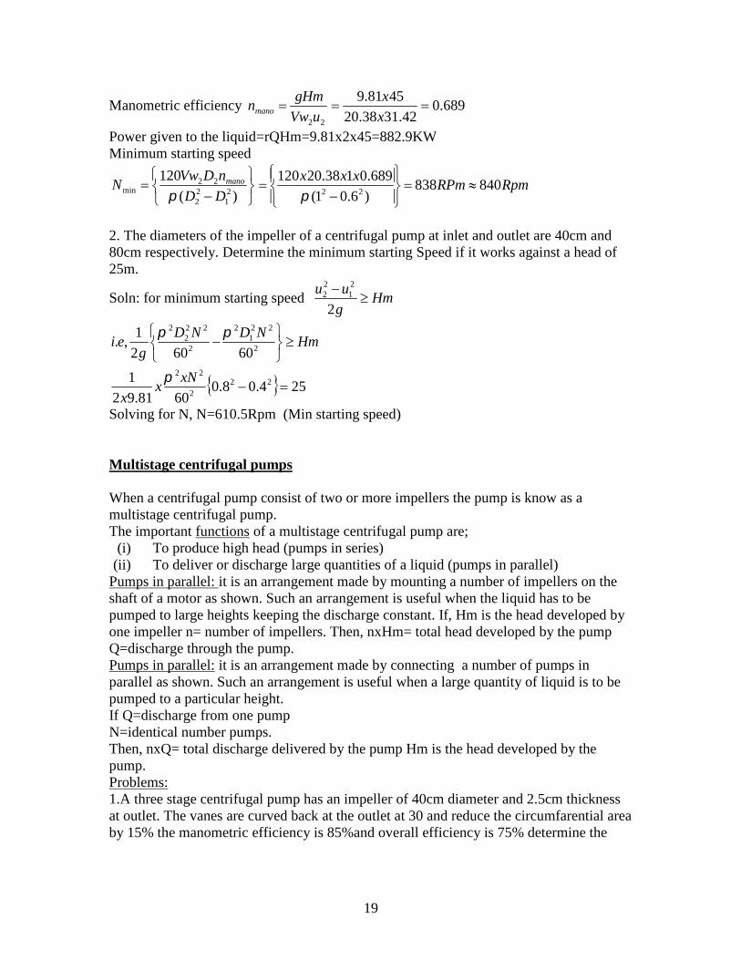
2. The diameters of the impeller of a centrifugal pump at inlet and outlet are 40cm and80cm respectively. Determine the minimum starting Speed if it works against a head of25m.
Soln: for minimum starting speed Hmg
uu
2
21
22
HmNDND
gei
2
221
2
2
222
2
60602
1,.
254.08.06081.92
1 222
22
xN
xx
Solving for N, N=610.5Rpm (Min starting speed)
Multistage centrifugal pumps
When a centrifugal pump consist of two or more impellers the pump is know as amultistage centrifugal pump.The important functions of a multistage centrifugal pump are;
(i) To produce high head (pumps in series)(ii) To deliver or discharge large quantities of a liquid (pumps in parallel)
Pumps in parallel: it is an arrangement made by mounting a number of impellers on theshaft of a motor as shown. Such an arrangement is useful when the liquid has to bepumped to large heights keeping the discharge constant. If, Hm is the head developed byone impeller n= number of impellers. Then, nxHm= total head developed by the pumpQ=discharge through the pump.Pumps in parallel: it is an arrangement made by connecting a number of pumps inparallel as shown. Such an arrangement is useful when a large quantity of liquid is to bepumped to a particular height.If Q=discharge from one pumpN=identical number pumps.Then, nxQ= total discharge delivered by the pump Hm is the head developed by thepump.Problems:1.A three stage centrifugal pump has an impeller of 40cm diameter and 2.5cm thicknessat outlet. The vanes are curved back at the outlet at 30 and reduce the circumfarential areaby 15% the manometric efficiency is 85%and overall efficiency is 75% determine the

20
head generated by the pump when running at 1200 Rpm and discharging 0.06m 3/s. findthe power required to drive the pump.
Soln: from the continuity equation 222 VfBDKQ K= total percentage area available for flow=(1-0.15)=0.85
2025.04.085.006.0 xVfxxx smVf /25.22
smxxND
u /13.2560
12004.0
602
2
From outlet velocity triangle22
2tanVwu
Vf
smVw /23.2130tan
25.213.25
02
Manometric efficiency22uVw
gHmnmano
mxx
Hor m 23.4681.9
85.013.2523.21
Total head developed by the pump H=3Hm=3x46.23=138.7mOutput of the pump P=rQh=9.81x0.06x138.7=81.64KW
Power required to drive the pump KWn
P85.108
75.0
64.81
0
2. Find the number of impellers and the diameter of each impeller required for amultistage centrifugal pump to lift 80lps of water against a total head of 225m. Assumespeed=1500Rpm, approximate specific speed=600 peripheral Coefficient=0.96 andoverall efficiency=80% what is the shaft input required
Soln: specific speed4
3
m
s
H
QNN
)(63600
801500 3
4
stageperheadmx
Hm
457.363
225orstagesofnumber
Diameter of each impeller mu HKN
85
mxx 432.06396.01500
85
KWxx
n
rQHminputshaft 7.220
8.0
22508.081.9
0
Specific speed (Ns)
21
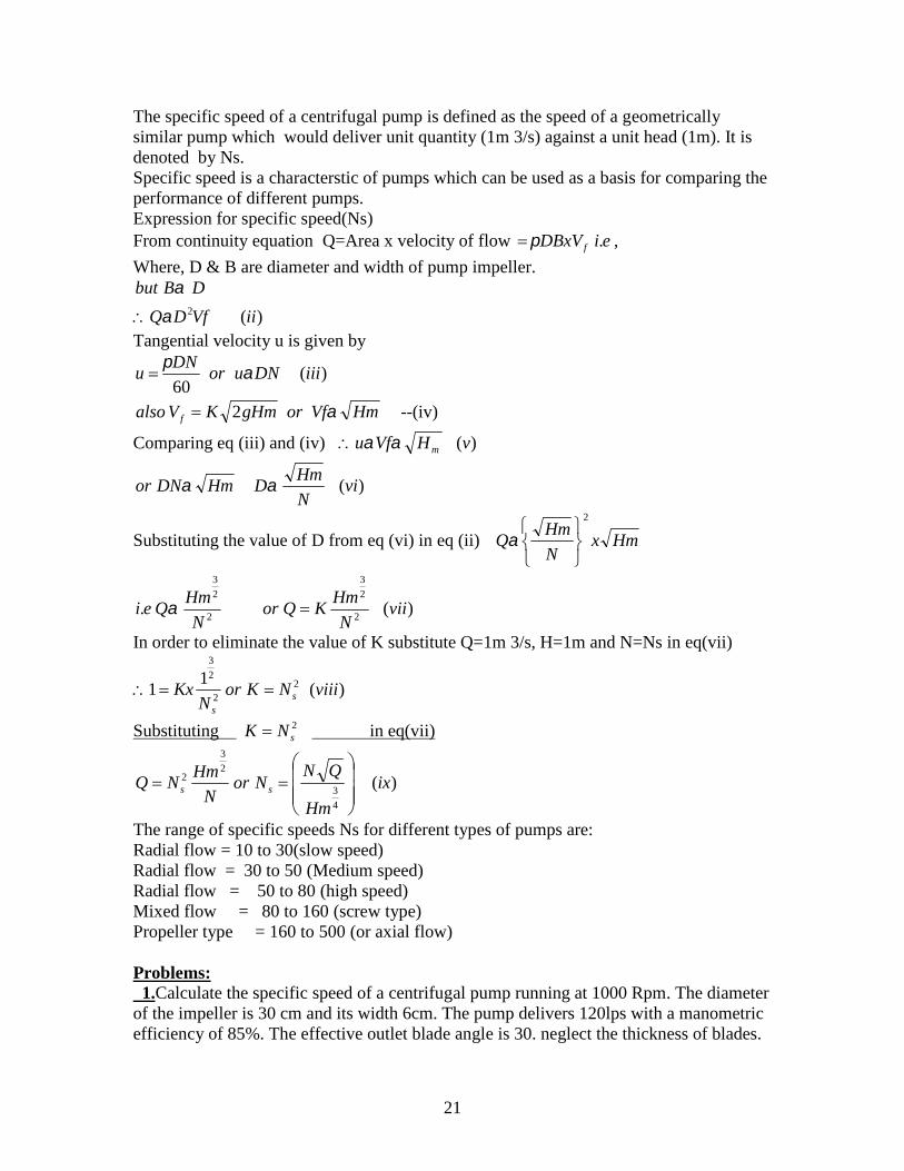
The specific speed of a centrifugal pump is defined as the speed of a geometricallysimilar pump which would deliver unit quantity (1m 3/s) against a unit head (1m). It isdenoted by Ns.Specific speed is a characterstic of pumps which can be used as a basis for comparing theperformance of different pumps.Expression for specific speed(Ns)From continuity equation Q=Area x velocity of flow fDBxV ,.ei
Where, D & B are diameter and width of pump impeller.
)(2 iiVfDQ
DBbut
Tangential velocity u is given by
)(60
iiiDNuorDN
u
HmVforgHmKValso f 2 --(iv)
Comparing eq (iii) and (iv) )(vHVfu m
)(viN
HmDHmDNor
Substituting the value of D from eq (vi) in eq (ii) HmxN
HmQ
2
2
2
3
.N
HmQei )(
2
2
3
viiN
HmKQor
In order to eliminate the value of K substitute Q=1m 3/s, H=1m and N=Ns in eq(vii)
)(1
1 22
2
3
viiiNKorN
Kx ss
Substituting 2sNK in eq(vii)
)(4
3
2
3
2 ix
Hm
QNNor
N
HmNQ ss
The range of specific speeds Ns for different types of pumps are:Radial flow = 10 to 30(slow speed)Radial flow = 30 to 50 (Medium speed)Radial flow = 50 to 80 (high speed)Mixed flow = 80 to 160 (screw type)Propeller type = 160 to 500 (or axial flow)
Problems:1.Calculate the specific speed of a centrifugal pump running at 1000 Rpm. The diameter
of the impeller is 30 cm and its width 6cm. The pump delivers 120lps with a manometricefficiency of 85%. The effective outlet blade angle is 30. neglect the thickness of blades.

22
Soln: smxxND
u /7.1560
10003.0
602
2
smxxflowofarea
QVf /12.2
06.03.0
12.01
From the outlet velocity triangle
smVf
uVw /03.1230tan
12.27.15
tan 02
22
From the definition of manometric efficiency 85.07.1503.12
81.9
22
x
xHm
uVw
gHmnmano
smHm /36.16
Specific speed 6.42
)36.16(
12.01000
4
3
4
3
x
Hm
QNN s
Performance of centrifugal pumps:
Generally a centrifugal pump is worked under its maximum efficiency conditions,however when the pump is run at conditions other than this it performs differently. Inorder to predict the behaviour of the pump under varying conditions of speed, dischargeand head, full scale tests are usually performed. The results of these tests are plotted inthe form of characteristic curves. These curves are very useful for predicting theperformance of pumps under different conditions of speed, discharge and head.Following four types of characteristic curves are usually prepared for a centrifugal pump.
a. Main characteristic.b. Operating characteristicsc. Constant efficiency or Muschel characteristic.d. Constant head an constant discharge curves.
Main Characteristic: the pump is operated a particular constant speed, discharge isvaried by adjusting the delivery valve. Manometric head Hm and the shaft power P aremeasured for each discharge. The overall efficiency is then calculated. The curves areplotted between Hm & Q, P & Q, & Q. A set of similar curves are plotted by runningthe pump at different speeds. They will be as shown.b. Operating characteristic: The curves are obtained by running the pump at the designspeed, which is also the driving speed of the motor. The design discharge and head areobtained from the corresponding Curves, where the efficiency is maximum as shown.c. Constant efficiency curves: The constant efficiency curves are obtained from themain characteristic curves. The line of maximum efficiency is obtained by joining thepoints of the maximum curvature of the constant efficiency lines. These curves are usefulin Determining the range of operation of a pump.d. Constant head and constant discharge curves: If the pump has a variable speed, theplots between Q and N and that between Hm and N may be obtained by varying thespeed. In the first case Hm is kept constant & in the second Q is kept contant.
23
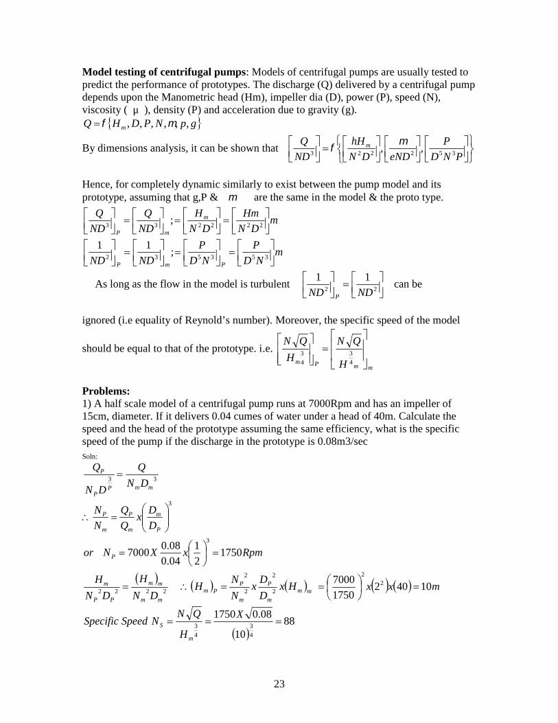
Model testing of centrifugal pumps: Models of centrifugal pumps are usually tested topredict the performance of prototypes. The discharge (Q) delivered by a centrifugal pumpdepends upon the Manometric head (Hm), impeller dia (D), power (P), speed (N),viscosity ( μ ), density (P) and acceleration due to gravity (g).
gpNPDHQ m ,,,,,,
By dimensions analysis, it can be shown that
PND
P
eNDDN
hH
ND
Q m352223
,,
Hence, for completely dynamic similarly to exist between the pump model and itsprototype, assuming that g,P & are the same in the model & the proto type.
mDN
Hm
DN
H
ND
Q
ND
Q m
mP
222233;
mND
P
ND
P
NDND PmP
353532;
11
As long as the flow in the model is turbulent
22
11
NDND P
can be
ignored (i.e equality of Reynold’s number). Moreover, the specific speed of the model
should be equal to that of the prototype. i.e.
mmPm H
QN
H
QN
4
33
4
Problems:1) A half scale model of a centrifugal pump runs at 7000Rpm and has an impeller of15cm, diameter. If it delivers 0.04 cumes of water under a head of 40m. Calculate thespeed and the head of the prototype assuming the same efficiency, what is the specificspeed of the pump if the discharge in the prototype is 0.08m3/secSoln:
33mmP
P
P
DN
Q
DN
Q
3
P
m
m
P
m
P
D
Dx
Q
Q
N
N
RpmxXNor P 17502
1
04.0
08.07000
3
2222
mm
mm
PP
m
DN
H
DN
H mm
m
P
m
PPm Hx
D
Dx
N
NH 2
2
2
2
mxx 104021750
7000 22
88
10
08.01750
4
3
4
3 X
H
QNNSpeedSpecific
m
S
24
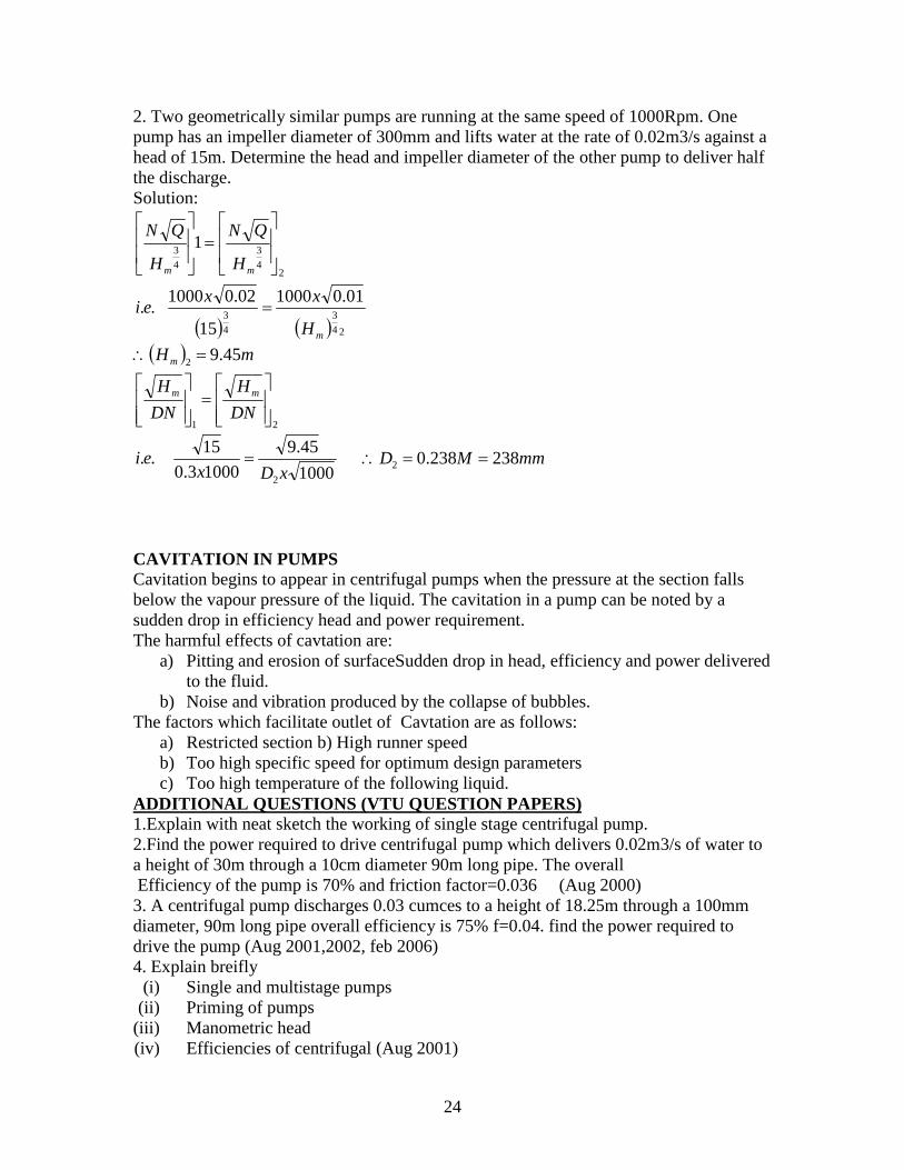
2. Two geometrically similar pumps are running at the same speed of 1000Rpm. Onepump has an impeller diameter of 300mm and lifts water at the rate of 0.02m3/s against ahead of 15m. Determine the head and impeller diameter of the other pump to deliver halfthe discharge.Solution:
24
3
4
3 1
mm H
QN
H
QN
24
3
4
3
01.01000
15
02.01000..
mH
xxei
mHm 45.92
21
DN
H
DN
H mm
1000
45.9
10003.0
15..
2xDxei mmMD 238238.02
CAVITATION IN PUMPSCavitation begins to appear in centrifugal pumps when the pressure at the section fallsbelow the vapour pressure of the liquid. The cavitation in a pump can be noted by asudden drop in efficiency head and power requirement.The harmful effects of cavtation are:
a) Pitting and erosion of surfaceSudden drop in head, efficiency and power deliveredto the fluid.
b) Noise and vibration produced by the collapse of bubbles.The factors which facilitate outlet of Cavtation are as follows:
a) Restricted section b) High runner speedb) Too high specific speed for optimum design parametersc) Too high temperature of the following liquid.
ADDITIONAL QUESTIONS (VTU QUESTION PAPERS)1.Explain with neat sketch the working of single stage centrifugal pump.2.Find the power required to drive centrifugal pump which delivers 0.02m3/s of water toa height of 30m through a 10cm diameter 90m long pipe. The overallEfficiency of the pump is 70% and friction factor=0.036 (Aug 2000)
3. A centrifugal pump discharges 0.03 cumces to a height of 18.25m through a 100mmdiameter, 90m long pipe overall efficiency is 75% f=0.04. find the power required todrive the pump (Aug 2001,2002, feb 2006)4. Explain breifly
(i) Single and multistage pumps(ii) Priming of pumps
(iii) Manometric head(iv) Efficiencies of centrifugal (Aug 2001)

25
(v) 5. What is priming in centrifugal pump? Derive an expressionFor the minimum speed for starting a centrifugal pump. (mar 2001)6. Explain pumps in series and pumps in parallel (mar 2001,july 2006)7. A centrifugal pump with 1.2m dia runs at 200 Rpm and pumps 1880lps at an averagelift 6m. The vane angle at exit with the tangent of impeller is 26 and theRadial flow velocity is 2.5 m/s. determine the manometric efficiency and the least speedto start the pump against a head of 6m. The inner diameter of impeller is 0.6m (march2001)8. Define the terms
(i) Section head(ii) Delivery head
(iii) Static head(iv) Manometric head (feb 2002)9. Show that the pressure rise in the impeller of a centrifugal pump is given by
222
22
21
12 cos2
1ecVfVVf
gr
PP
10. Definea) Manometric headb) Manometric efficiencyc) Mechanical efficiencyd) Overall efficiency (Feb 2002, july 2006)11. Differentiate Manometric efficiency and volumetric efficiencyStatic head and manometric head (feb 2003)
12. A centrifugal pump has a outer diameter equal to two times the inner diameter andrunning at 1000 Rpm works against a head of 40m velocity of flow through the impelleris constant and is equal To 2.5 m/s . The vanes are set back at an angle of 40 at outlet. Ifthe outer diameter of the impeller is 0.5m and width is 0.05m determine
• Vane angle at inlet• Work done/see by impeller• Manometric efficiency (feb2003)
13. What is priming? Why is it necessary? Mention any two Priming devices (feb2003)14. Obtain an expression for the minimum speed for starting a centrifugal pump (feb2003)15.A centrifugal pump discharge 0.15 m3/s of water against a head of 12.5m the speed ofthe impeller being 600 Rpm. The outer and inner diameter of impeller are 500mm and250mm respectively. and the vanes are bent back at 35 to the tangent at exit. If area offlow is 0.07m from inlet to outlet calculate
• Manometric efficiency of the pump• Vane angle at inlet• Loss of head at inlet to impeller when the discharge is reduced by 40% without
changing the speed (feb 2004)
16. Explain the losses and efficiencies of centrifugal pump (aug 2004)
17. Derive the expressiong
VdhfhfhhHm dssd 2
2

26
For a centrifugal pump where Hm = manometric head dh =delivery head
sh =suction head
Friction loss in section and deliveryPipes
= velocity in delivery pipe (aug 2004)18. A centrifugal pump of the radial type delivers 5000lpm against a total head of38m, when running at a speed of 1450 Rpm. If the outer diameter of the impeller is30cm & its width at the outer periphery is 1.30cm. Find the vane angle atExit. Assume manometric efficiency as 80% (Aug 2004)19. Define specific speed of a centrifugal pump derive and expression for the same(aug 2005)20. A single stage centrifugal pump with impeller diameter of 30cm rotates at 2000Rpm and lifts 3 m3/s of water to a height of 30mWith an efficiency of 75%. Find the number of stages and diameter of each impellerof a similar multistage pump to lift 5 m3/s to a height of 200m. When rotating at 1500Rpm. (aug 2005)21. Distinguish between pumps in series and parallel (feb 2006)22. Differentiate the followinga) Pump and turbineb) Section head and delivery headc) Manometric and overall efficiencyd) Single stage and multi stage pump (feb 2005)23. With a neat sketch explain the various components of a centrifugal pump. Why isit necessary to prime the centrifugal pump (aug 2005, feb 2006 jan 2007)24. A centrifugal pump delivers 3000lpm of water against a head of 24m. The bladesare curved backwards at 30 to the tangent at exit and the pump runs at 1500 Rpmassuming a flow velocity of 2.4m/s as constant throughout the machine. Amanometric efficiency of 80% and inner diameter one half of the outer diameter. Findthe blade angle at inlet and power expended by the pump (aug 2005)25. The diameter of centrifugal pump at inlet and outlet are 30cm and 60cmrespectively. Determine the minimum starting speed of the pump if it works againsthead of 30m.26. The internal and external diameter of the impeller of a centrifugal pump are200mm and 400mm respectively. The pump is running at 1200Rpm . The vane angleof the impeller at inlet and outlet are 20 and 30 respectively. The water enters theimpeller radially and velocity of flow is constant. Determine the work done by theimpeller per unit height of water.27. A centrifugal pump delivers 30lps to a height of 18m through a 100mm diameter100m long pipe. If the overall efficiency is 75% find the power required to drive the
pump. Use the expression for 01.0&2
2
fgd
FlVhf head loss due to friction in the
pipe
* * * * *

27