centralised heat recovery units
TRANSCRIPT

QRCE
104 INDUSTRIAL CATALOGUE
ACCESSORIES
•Rainproof cowl.•Multiport plenum.•Adjusting damper.•Damper on/off actuator.•Flexible connector.•Round connection.•Differential pressure sensor.•Ductable CO
2 sensor.
•Electric heater for pre/post heating.•External direct expansion heating/
cooling module.•External water heating/cooling module.•3-way modulating valve.
CEntRAlisED hEAtRECOvERy units
APPLICATION
Centralised heat recovery units designed to ensure a correct ventilation in apartment blocks or non-residential buildings which can be used as an independent ventilation system or in combination with traditional heating/cooling systems. suitable for a working environment free of aggressive, corrosive and/or explosive agents.
CONSTRUCTION
•self-supporting structure made from externally coated steel panels (RAl 9002) and internally galvanised, with 25mm thick mineral wool acoustic and thermal insulation, A2s1d0 fire rated.
•EC external rotor motors mounted on sealed for life ball bearings for energy saving, provided with thermal protection.
•Backward curved centrifugal impeller dynamically balanced and directly coupled with the motor; made from fiberglass reinforced plastic for sizes 500 and 1000 and from aluminum for the bigger ones.
•M5 filter on return air and F7 on fresh air efficiency calculated according to En 779:2012.
•high efficient counterflow plate heat exchanger (>75%) made from aluminum.
•Motorised by-pass device for free cooling.
•Aluminum condensation drainage tray.•Multifunction electronic control on
board.•Operating temperatures between
-20°C and +45°C and h.R. not higher than 95%.
FEATURES & BENEFITS
•units are available in 6 sizes from 300m3/h to 4.300m3/h, in horizontal or vertical version.
•Easy installation thanks to the ceiling bracket (horizontal version) or to the mounting feet (vertical version).
•Equipped with pressure switches to control the filters status.
•Easy removable filters for maintenance, from bottom or lateral side.
•the unit is supplied with a multi-function lCD display, providing manual/automatic speed control, monitoring of the filters status, weekly program, free cooling, alarm management, defrost management, water coil antifreeze sensor enable and proportional valve control, pre/post electric heater proportional control.
•BMs connection through Modbus protocol and Rs485.
•tested to the latest standards, meaning accurate, up to date information on electrical safety, performance and noise level that can be relied upon.
•Designed and manufactured in accordance with Machinery Directive (MD), low voltage Directive (lvD), Electromagnetic Compatibility Directive (EMC) and Regulation 1253/2014 (Erp Directive).
MULTIFUNCTIONAL LCD DISPLAY CONTROLLER
(supplied)
ErP1253
PLEASE CONTACT
AERAULIQA DIRECLTY FOR
A SPECIFIC FAN SELECTION

QRCE
105INDUSTRIAL CATALOGUE
Performance*
QRCE 500
QRCE 2000QRCE 1500
QRCE 1000
QRCE 3000 QRCE 4000
* the indicated performance refer to the unit with cleaned and duly maintained filters.
0
150
300
450
600
750
900
100 200 300 400 500 600 700
Pres
sion
e st
atic
a -P
a
Portata d'aria - m³/h
100%
80%
60%
0
100
200
300
400
500
600
300 400 500 600 700 800 900
Pres
sion
e st
atic
a -P
a
Portata d'aria - m³/h
100%
80%
60%
0
150
300
450
600
750
900
400 600 800 1000 1200 1400 1600
Pres
sion
e st
atic
a -P
a
Portata d'aria - m³/h
100%
80%
60%
0
150
300
450
600
750
900
600 850 1100 1350 1600 1850 2100
Pres
sion
e st
atic
a -P
a
Portata d'aria - m³/h
100%
80%
60%
0
150
300
450
600
750
900
1000 1400 1800 2200 2600 3000 3400
Pres
sion
e st
atic
a -P
a
Portata d'aria - m³/h
100%
80%
60%
0
150
300
450
600
750
900
1200 1700 2200 2700 3200 3700 4200
Pre
ssio
ne s
tatic
a -P
a
Portata d'aria - m³/h
100%
80%
60%
Airflow - m3/h
sta
tic P
ress
ure
- P
a
Airflow - m3/h
sta
tic P
ress
ure
- P
a
Airflow - m3/h
sta
tic P
ress
ure
- P
a
Airflow - m3/h
sta
tic P
ress
ure
- P
a
Airflow - m3/h
sta
tic P
ress
ure
- P
a
Airflow - m3/h
sta
tic P
ress
ure
- P
a

QRCE
106 INDUSTRIAL CATALOGUE
QRCE Model 500 1000 1500 2000 3000 4000
Airflow rate Nom m3/h 380 720 1130 1710 2460 3300
External static pressure(1) Nom Pa 340 230 360 270 430 340
Overall power inputNom
W340 340 920 930 1890 1920
Max 340 340 920 930 2000 2000
Overall input currentNom
A2,8 2,9 6,0 6,0 3,3 3,4
Max 2,8 2,9 6,0 6,0 3,4 3,5
Power supply V-Ph-Hz 230-1-50 400-3+N-50
Fan speed control - 0÷10 V
External leakage % max 3,5% @ -400 Pa (EN 13141-7)
Internal leakage % max 5,5% @ +250 Pa (EN 13141-7)
Yearly filter energy consumption(2) kWh 420 670 1200 1700 2085 2787
Recovery efficiency(3) % 88,8 88,1 86,5 86,3 85,8 85,9
Recovery capacity(3) W 3030 5690 8740 13230 19090 25600
Supply temperature(3) °C 17,0 16,8 16,3 16,3 16,2 16,2
QRCE Model 500 1000 1500 2000 3000 4000
Recovery efficiency(4) % 81,2 80,1 77,6 77,2 76,6 76,8
Efficiency bonus W/m3/s 246 213 138 126 108 114
Filter correction factor - 0 0 0 0 0 0
SFP int limit W/m3/s 1330 1283 1191 1154 1106 1076
Total internal air pressure drop(4) Pa 572 651 560 556 636 625
Overall fan static efficiency(5) % 44,3 53,7 47,1 50,3 59,0 59,2
SFP int W/m3/s 1291 1212 1189 1105 1078 1056
(4) at dry conditions: outside air temperature 5°C, room air temperature 25°C;(5) including motor & speed controller efficiency.
Conformity to EU 1253/2014
lpdB(A) at 5m for comparative purposes only in ducted unit configuration
* referring to nominal working conditions.
Noise levels*
QRCE ModelOctave band(Hz)
500 1000 1500 2000 3000 4000
SWL [dB]sound power values in octave bands
63 62 61 60 66 69 68125 59 58 59 64 66 69250 65 64 65 74 74 72500 65 64 65 73 76 731K 63 62 63 69 72 692K 63 62 63 68 67 664K 62 61 63 68 67 668K 53 53 55 67 67 65
Total SWL [dB] - 72 71 72 79 80 79
Total SWL [dB(A)] - 69 68 70 76 77 76
SPL SUPPLY [dB(A)] - sound pressure level - 47 47 48 54 55 54
SPL RETURN [dB(A)] - sound pressure level - 39 39 40 46 47 46
SPL OUTSIDE [dB(A)] - sound pressure level - 30 30 31 37 38 37
(1) fresh air/supply air circuit;(2) based on 6000 operating hours per year at nominal airflow rate, at fan efficiency (4) and on 150 Pa max air filter pressure drop before replacing (both M5 and F7 filter);(3) at wet conditions: outside air temperature –7°C 80% Rh, room air temperature 20°C 55% Rh.
Performance and Compliance with ErP Directive, Regulation 1253/2014
QRCE QRCE
107INDUSTRIAL CATALOGUE
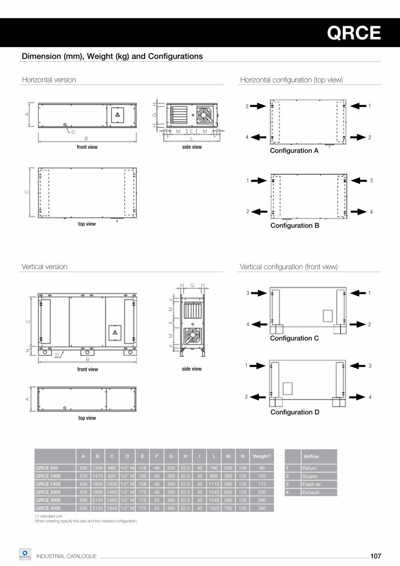
Dimension (mm), Weight (kg) and Configurations
When ordering specify the size and the needed configuration.(1) standard unit
A B C D E F G H I L M N Weight(1)
QRCE 500 330 1350 680 1/2” M 128 46 225 52,5 40 760 230 120 85
QRCE 1000 370 1470 820 1/2” M 130 46 265 52,5 40 900 300 120 105
QRCE 1500 455 1850 1030 1/2” M 158 46 350 52,5 40 1110 390 120 175
QRCE 2000 455 1850 1460 1/2” M 170 46 350 52,5 40 1540 600 120 230
QRCE 3000 590 2150 1460 1/2” M 170 55 485 52,5 40 1540 590 120 290
QRCE 4000 590 2150 1840 1/2” M 170 55 485 52,5 40 1920 780 120 360
B
A
D
Cn
FM
ME
h hG
F
A
BD
l
EFF
ii
G
hh
C
M M
3
4
1
2
3
4
1
2
3
4
1
2
3
4
1
2
top view
front view side view
top view
front view side view
Configuration A
Configuration B
Airflow
1 Return
2 Supply
3 Fresh air
4 Exhaust
horizontal version horizontal configuration (top view)
vertical version vertical configuration (front view)
Configuration C
Configuration D

QRCE
108 INDUSTRIAL CATALOGUE
DescriptionRainproof
cowl*Multiport plenum
Adjusting damperDamperon/off
actuator
Page 105 106 106 106
Description Code Description Code Description Code Description Code Description Code Description Code
QRCE 500 TPR-H 05 001578 TPR-CH 05 001778 PLM 05 001748 SKR1 05 001755 SKR2 05 001761
SSE 001754
QRCE 1000 TPR-H 10 001579 TPR-CH 10 001779 PLM 10 001749 SKR1 10 001756 SKR2 10 001762
QRCE 1500 TPR-H 15 001580 TPR-CH 15 001780 PLM 15 001750 SKR1 15 001757 SKR2 15 001763
QRCE 2000 TPR-H 20 001581 TPR-CH 20 001781 PLM 20 001751 SKR1 20 001758 SKR2 20 001764
QRCE 3000 TPR-H 30 001582 TPR-CH 30 001782 PLM 30 001752 SKR1 30 001759 SKR2 30 001765
QRCE 4000 TPR-H 40 001583 TPR-CH 40 001783 PLM 40 001753 SKR1 40 001760 SKR2 40 001766
Accessories
DescriptionFlexible
connectorRound
connection
Differentialpressuresensor
DuctableCO2
sensor
Page 106 107 107 107
Description Code Description Code Description Code Description Code Description Code Description Code
QRCE 500 GAT1 05 001767 GAT2 05 001768 BCC1 05 001590 BCC2 05 001772
DPS 001770 AQS 001771
QRCE 1000 GAT1 10 001797 GAT2 10 001802 BCC1 10 001591 BCC2 10 001773
QRCE 1500 GAT1 15 001798 GAT2 15 001803 BCC1 15 001592 BCC2 15 001774
QRCE 2000 GAT1 20 001799 GAT2 20 001804 BCC1 20 001593 BCC2 20 001775
QRCE 3000 GAT1 30 001800 GAT2 30 001805 BCC1 30 001594 BCC2 30 001776
QRCE 4000 GAT1 40 001801 GAT2 40 001806 BCC1 40 001595 BCC2 40 001777
DescriptionElectric heater
for pre/postheating
External directexpansion
heating/coolingmodule*
External waterheating/cooling
module*
3-waymodulating
valve
Page 107 108 108 108
Description Code Description Code Description Code Description Code
QRCE 500 SKE 05 001730 CDX-H 05 001742 CCS-H 05 001584 V33 05 001736
QRCE 1000 SKE 10 001731 CDX-H 10 001743 CCS-H 10 001585 V33 10 001737
QRCE 1500 SKE 15 001732 CDX-H 15 001744 CCS-H 15 001586 V33 15 001738
QRCE 2000 SKE 20 001733 CDX-H 20 001745 CCS-H 20 001587 V33 20 001739
QRCE 3000 SKE 30 001734 CDX-H 30 001746 CCS-H 30 001588 V33 30 001740
QRCE 4000 SKE 40 001735 CDX-H 40 001747 CCS-H 40 001589 V33 40 001741
* the above codes refer to the horizontal version.
Rainproof cowl
•Made of coated steel. •tPR-h (horizontal) and tPR-v (vertical) are needed to protect the
unit in case of outdoor installation.•tPR-Ch (horizontal) and tPR-Cv (vertical) are needed to protect the
CCs or CDX module in case of outdoor installation.

QRCE QRCE
109INDUSTRIAL CATALOGUE
Multiport plenum
•External multiport module to be directly connected to the unit on both front sides.
•Allows air inlet and outlet in all directions.•Can be match with sKR1 and sKR2 adjusting dampers.
Description A B CNominal air
pressure drop (Pa)Weight (kg)
PLM 05 330 340 680 6 21
PLM 10 370 380 820 9 23
PLM 15 455 460 1030 19 26
PLM 20 455 460 1460 14 30
PLM 30 590 580 1460 8 39
PLM 40 590 580 1840 14 44
Adjusting damper
•Frame and aluminum opposing blades controlled by on/off electrical actuator ssE (on request).
•Can be coupled directly on the air inlets of the unit, of the PlM plenum or CCs/CDX modules (select the sKR1 or sKR2 type make in reference to the drawing alongside).
Description L H Weight (kg)
SKR1 05 250 230 1,6
SKR1 10 290 270 2,1
SKR1 15 370 355 2,6
SKR1 20 610 355 3,7
SKR1 30 610 490 4,3
SKR1 40 770 490 6,2
Description SSE
Code 001754
Damper on/off actuator
•230v-50hz.•2nm torque.•Power consumption 1,5W.•supplied already mounted on the damper.
Dimensions in mm
Description L H Weight (kg)
SKR2 05 250 230 1,6
SKR2 10 290 270 2,1
SKR2 15 370 355 2,6
SKR2 20 370 355 2,9
SKR2 30 490 490 4,0
SKR2 40 490 490 4,0
Dimensions in mm
CA
B
Flexible connector
•Allows the flexible connection between the basic unit or its possible external sections and the air ducts.
•Cuts off the transmission of the vibrations to the ducts.•Dimensions are the same of the corresponding sKR1/sKR2.

QRCE
110 INDUSTRIAL CATALOGUE
Round connection
•Made from galvanised steel.•Provided with coupling flange.•BCC1 model allows the connection between the ventilation unit or
the heating/cooling module CCs-h, sKR-1 shutter, GAt1 flexible connector and round ducts.
•BCC2 model allows the connection of the sKR-2 shutter and GAt2 flexible connector to round ducts.
Description ØA B C DNominal air
pressure drop (Pa)Weight (kg)
BCC1/BCC2 05 250 100 250 230 7 1,6
BCC1/BCC2 10 315 100 290 270 7 2
BCC1/BCC2 15 315 100 370 355 16 2,6
BCC1/BCC2 20 400 100 370 355 10 2,9
BCC1/BCC2 30 500 100 490 490 9 4
BCC1/BCC2 40 500 100 490 490 16 4
Differential pressure sensor
•Differential pressure sensor for constant airflow control. •Already mounted and wired on the basic unit.
Ductable CO2 sensor
•CO2 sensor ductable type.
•it allows a continuous modulation of the airflow, based on air quality desired level.
(1) at nominal airflow rate.
Electric heater for pre/post heating
•Mounted on the unit.•Galvanised steel frame.•Filament type elements.•Equipped with both automatic and manual reset thermostats.
DescriptionCapacity
(kW)ΔT(1)
(°C)Air pressuredrop(1) (Pa)
Power supply (V-ph-Hz)
SKE 05 1,5 9,8 5
230-1-50SKE 10 2,5 9,2 6
SKE 15 4 9 10
SKE 20 5 7,7 10
SKE 30 7,5 7,9 11400-3-50
SKE 40 10,5 8,1 12
280
280
100
Ø250280
280
100
Ø250
ØA
B
C
D
Dimensions in mm

QRCE QRCE
111INDUSTRIAL CATALOGUE
(1) air inlet condition 28,0°C 60% Rh; evaporating temperature 8°C.(2) air inlet condition 13°C; condensing temperature 45°C.Dimensions in mm
External direct expansion heating/cooling module
•External module directly connected to the unit on air supply/return side.
•3-row direct expansion module suitable for R410A. •Complete with aluminum dray tray.
Description A B C DCooling
capacity(1) (kW)
Heating capacity(2)
(kW)
Airpressure
drop(1) (Pa)
ODS connect.
Weight (kg)
tot sens
CDX-H 05 330 350 1/2”M 680 2,51 1,41 3,33 51 8/8 28
CDX-H 10 370 400 1/2”M 820 4,36 2,44 5,71 53 12/16 31
CDX-H 15 455 400 1/2”M 1030 7,13 3,99 9,22 54 12/16 35
CDX-H 20 455 400 1/2”M 1460 10,94 6,13 13,90 50 12/16 42
CDX-H 30 590 502 1/2”M 1460 16,11 9,02 20,36 50 16/22 52
CDX-H 40 590 502 1/2”M 1840 21,22 11,88 26,50 55 22/28 58
(1) air inlet condition 28,0°C 60% Rh; in/out water temperature 7°/12°C;(2) air inlet condition 13°C; in/out water temperature 45°/40°C.A, B, C, D: see dimensions in “External direct expansion heating/cooling module” table.
External water heating/cooling module
•External module directly connected to the unit on air supply/return side.
•3-row water module for heating/cooling •Complete with aluminum dray tray.
DescriptionCooling
capacity(1) (kW)
Heating capacity(2)
(kW)
Waterflow rate(1)
(l/h)
Waterpressure
drop(1) (kPa)
Airpressure
drop(1) (Pa)
Weight (kg)
tot sens
CCS-H 05 2,46 1,35 3,30 432 12 51 28
CCS-H 10 4,47 2,41 5,86 756 18 53 31
CCS-H 15 6,83 3,76 9,34 1188 9 54 35
CCS-H 20 10,62 5,84 14,03 1836 13 50 42
CCS-H 30 16,14 8,72 20,83 2772 19 50 52
CCS-H 40 20,68 11,37 27,50 3564 15 55 58
D
B
A
C D
120CB
A
D
B
A
C D
120CB
A
3-way modulating valve
•3-way water valve to adjust the water flow of the CCs-h module.•With modulating electric actuator. •Fittings and connecting pipes not included.
DescriptionNominal pressure
(-)
Lift (mm)
Waterconnection
(GAS)
Kvs (m3/h)
Water temp.(°C)
Powersupply(V-Hz)
Control signal
(V)
V33 05
PN16(ISO7286/EN1333)
2,5
3/4” F 2,5
+2÷95(glic. max
40%)24cc - 50/60 0÷10
V33 10
V33 153/4” F 4
V33 20
V33 305,5 1” F 10
V33 40