central unit for alarm system (cuas) evaluation board 2006 rev 1 1/40 um0272 user manual central...
TRANSCRIPT

September 2006 Rev 1 1/40
UM0272User manual
Central Unit for Alarm System (CUAS) Evaluation Board
IntroductionThe Central Unit for Alarm System (CUAS) Evaluation Board provides a complete reference system addressing the low- to middle-end security sectors. The tool is ready, from hardware and software point of view, for the development of a complete alarm platform based on a bus network. Thanks to a PC graphical user interface (GUI), it is also possible to easily set up all control parameters (in addition to a control/programming panel connected through the bus).
The entire system consists of four boards: Central Unit (CU) board, Control Module (CM) board, Power Supply (PS) board and the PC interface board. There is also PC GUI software that enables the user to easily configure all CU parameters and to execute certain system tests. It is possible to expand the system by means of input/output expansion boards, a GSM board (a connector is available on the CU Board) for managing the CU using a cell phone and other modules using radio-frequency identification (RFID), smartcard or keyboard devices connected through the bus.
www.st.com

Contents UM0272
2/40
Contents
1 System features . . . . . . . . . . . . . . . . . . . . . . . . . . . . . . . . . . . . . . . . . . . . . 6
1.1 System description . . . . . . . . . . . . . . . . . . . . . . . . . . . . . . . . . . . . . . . . . . . 6
1.2 Getting started . . . . . . . . . . . . . . . . . . . . . . . . . . . . . . . . . . . . . . . . . . . . . . 8
2 System parameters . . . . . . . . . . . . . . . . . . . . . . . . . . . . . . . . . . . . . . . . . 11
2.1 Introduction . . . . . . . . . . . . . . . . . . . . . . . . . . . . . . . . . . . . . . . . . . . . . . . 11
2.2 Zones . . . . . . . . . . . . . . . . . . . . . . . . . . . . . . . . . . . . . . . . . . . . . . . . . . . . 11
2.3 Outputs . . . . . . . . . . . . . . . . . . . . . . . . . . . . . . . . . . . . . . . . . . . . . . . . . . . 11
2.4 Partitions . . . . . . . . . . . . . . . . . . . . . . . . . . . . . . . . . . . . . . . . . . . . . . . . . 12
2.5 Log events . . . . . . . . . . . . . . . . . . . . . . . . . . . . . . . . . . . . . . . . . . . . . . . . 12
2.6 Options . . . . . . . . . . . . . . . . . . . . . . . . . . . . . . . . . . . . . . . . . . . . . . . . . . . 12
3 System hardware configuration . . . . . . . . . . . . . . . . . . . . . . . . . . . . . . . 13
3.1 Introduction . . . . . . . . . . . . . . . . . . . . . . . . . . . . . . . . . . . . . . . . . . . . . . . 13
3.2 Sensor connections . . . . . . . . . . . . . . . . . . . . . . . . . . . . . . . . . . . . . . . . . 13
3.3 Control module connections . . . . . . . . . . . . . . . . . . . . . . . . . . . . . . . . . . . 14
3.4 Power supply connections . . . . . . . . . . . . . . . . . . . . . . . . . . . . . . . . . . . . 14
3.5 Central unit connections . . . . . . . . . . . . . . . . . . . . . . . . . . . . . . . . . . . . . . 14
3.6 Output connections . . . . . . . . . . . . . . . . . . . . . . . . . . . . . . . . . . . . . . . . . 15
3.7 Tamper line . . . . . . . . . . . . . . . . . . . . . . . . . . . . . . . . . . . . . . . . . . . . . . . . 16
4 Configuring system parameters . . . . . . . . . . . . . . . . . . . . . . . . . . . . . . 17
4.1 Introduction . . . . . . . . . . . . . . . . . . . . . . . . . . . . . . . . . . . . . . . . . . . . . . . 17
4.2 Configuration using the PC GUI . . . . . . . . . . . . . . . . . . . . . . . . . . . . . . . . 17
4.3 Configuration using the Control Module . . . . . . . . . . . . . . . . . . . . . . . . . . 17
4.4 Password protection . . . . . . . . . . . . . . . . . . . . . . . . . . . . . . . . . . . . . . . . . 18
4.5 Access levels . . . . . . . . . . . . . . . . . . . . . . . . . . . . . . . . . . . . . . . . . . . . . . 19
4.5.1 User level . . . . . . . . . . . . . . . . . . . . . . . . . . . . . . . . . . . . . . . . . . . . . . . . 19
4.5.2 Service and owner levels (S/O-L) . . . . . . . . . . . . . . . . . . . . . . . . . . . . . 19
5 Menus . . . . . . . . . . . . . . . . . . . . . . . . . . . . . . . . . . . . . . . . . . . . . . . . . . . . 21
5.1 Using the key pad . . . . . . . . . . . . . . . . . . . . . . . . . . . . . . . . . . . . . . . . . . . 21

UM0272 Contents
3/40
5.2 System Enable/Disable . . . . . . . . . . . . . . . . . . . . . . . . . . . . . . . . . . . . . . 21
5.3 Partition Enable/Select . . . . . . . . . . . . . . . . . . . . . . . . . . . . . . . . . . . . . . . 21
5.4 System status . . . . . . . . . . . . . . . . . . . . . . . . . . . . . . . . . . . . . . . . . . . . . . 22
5.5 Log event . . . . . . . . . . . . . . . . . . . . . . . . . . . . . . . . . . . . . . . . . . . . . . . . . 22
5.6 Setup . . . . . . . . . . . . . . . . . . . . . . . . . . . . . . . . . . . . . . . . . . . . . . . . . . . . 24
5.6.1 Zones . . . . . . . . . . . . . . . . . . . . . . . . . . . . . . . . . . . . . . . . . . . . . . . . . . . 24
5.6.2 Outputs . . . . . . . . . . . . . . . . . . . . . . . . . . . . . . . . . . . . . . . . . . . . . . . . . 27
5.6.3 Partitions . . . . . . . . . . . . . . . . . . . . . . . . . . . . . . . . . . . . . . . . . . . . . . . . 29
5.6.4 Installation code . . . . . . . . . . . . . . . . . . . . . . . . . . . . . . . . . . . . . . . . . . . 30
5.6.5 Access code . . . . . . . . . . . . . . . . . . . . . . . . . . . . . . . . . . . . . . . . . . . . . 31
5.6.6 Options . . . . . . . . . . . . . . . . . . . . . . . . . . . . . . . . . . . . . . . . . . . . . . . . . 31
5.6.7 Timer events . . . . . . . . . . . . . . . . . . . . . . . . . . . . . . . . . . . . . . . . . . . . . 32
5.6.8 Date and time . . . . . . . . . . . . . . . . . . . . . . . . . . . . . . . . . . . . . . . . . . . . 32
5.6.9 Bus modules . . . . . . . . . . . . . . . . . . . . . . . . . . . . . . . . . . . . . . . . . . . . . 33
5.6.10 Central Unit . . . . . . . . . . . . . . . . . . . . . . . . . . . . . . . . . . . . . . . . . . . . . . 36
5.7 CM Setup . . . . . . . . . . . . . . . . . . . . . . . . . . . . . . . . . . . . . . . . . . . . . . . . . 36
6 Electrical characteristics . . . . . . . . . . . . . . . . . . . . . . . . . . . . . . . . . . . . 37
Appendix A Miscellaneous . . . . . . . . . . . . . . . . . . . . . . . . . . . . . . . . . . . . . . . . . . 38
A.1 Keyboard character association . . . . . . . . . . . . . . . . . . . . . . . . . . . . . . . . 38
A.2 Module address ranges. . . . . . . . . . . . . . . . . . . . . . . . . . . . . . . . . . . . . . . 38
A.3 Output assignments . . . . . . . . . . . . . . . . . . . . . . . . . . . . . . . . . . . . . . . . . 38
Revision history . . . . . . . . . . . . . . . . . . . . . . . . . . . . . . . . . . . . . . . . . . . . . . . . . . . . 39

List of tables UM0272
4/40
List of tables
Table 1. CU connectors . . . . . . . . . . . . . . . . . . . . . . . . . . . . . . . . . . . . . . . . . . . . . . . . . . . . . . . . . . 15Table 2. Password protection for each access level. . . . . . . . . . . . . . . . . . . . . . . . . . . . . . . . . . . . . 18Table 3. Menus available by access level . . . . . . . . . . . . . . . . . . . . . . . . . . . . . . . . . . . . . . . . . . . . 19Table 4. Electrical characteristics . . . . . . . . . . . . . . . . . . . . . . . . . . . . . . . . . . . . . . . . . . . . . . . . . . . 37Table 5. List of available characters . . . . . . . . . . . . . . . . . . . . . . . . . . . . . . . . . . . . . . . . . . . . . . . . . 38Table 6. List of possible module addresses . . . . . . . . . . . . . . . . . . . . . . . . . . . . . . . . . . . . . . . . . . . 38Table 7. Output assignments . . . . . . . . . . . . . . . . . . . . . . . . . . . . . . . . . . . . . . . . . . . . . . . . . . . . . . 38Table 8. Document revision history . . . . . . . . . . . . . . . . . . . . . . . . . . . . . . . . . . . . . . . . . . . . . . . . . 39

UM0272 List of figures
5/40
List of figures
Figure 1. System overview. . . . . . . . . . . . . . . . . . . . . . . . . . . . . . . . . . . . . . . . . . . . . . . . . . . . . . . . . . 7Figure 2. Central unit board layout. . . . . . . . . . . . . . . . . . . . . . . . . . . . . . . . . . . . . . . . . . . . . . . . . . . . 9Figure 3. PC interface board layout . . . . . . . . . . . . . . . . . . . . . . . . . . . . . . . . . . . . . . . . . . . . . . . . . . 10Figure 4. Control module board layout. . . . . . . . . . . . . . . . . . . . . . . . . . . . . . . . . . . . . . . . . . . . . . . . 10Figure 5. Power supply board layout . . . . . . . . . . . . . . . . . . . . . . . . . . . . . . . . . . . . . . . . . . . . . . . . . 10Figure 6. Sensor wiring diagram . . . . . . . . . . . . . . . . . . . . . . . . . . . . . . . . . . . . . . . . . . . . . . . . . . . . 13Figure 7. Control module connections . . . . . . . . . . . . . . . . . . . . . . . . . . . . . . . . . . . . . . . . . . . . . . . . 14Figure 8. Siren connection . . . . . . . . . . . . . . . . . . . . . . . . . . . . . . . . . . . . . . . . . . . . . . . . . . . . . . . . . 16Figure 9. Status/alarm connector . . . . . . . . . . . . . . . . . . . . . . . . . . . . . . . . . . . . . . . . . . . . . . . . . . . 16Figure 10. Central unit connected message . . . . . . . . . . . . . . . . . . . . . . . . . . . . . . . . . . . . . . . . . . . . 17Figure 11. Control module keypad . . . . . . . . . . . . . . . . . . . . . . . . . . . . . . . . . . . . . . . . . . . . . . . . . . . 18Figure 12. User level menus . . . . . . . . . . . . . . . . . . . . . . . . . . . . . . . . . . . . . . . . . . . . . . . . . . . . . . . . 19Figure 13. Service / owner level menus . . . . . . . . . . . . . . . . . . . . . . . . . . . . . . . . . . . . . . . . . . . . . . . 20Figure 14. Text entry . . . . . . . . . . . . . . . . . . . . . . . . . . . . . . . . . . . . . . . . . . . . . . . . . . . . . . . . . . . . . . 21Figure 15. Partition selection . . . . . . . . . . . . . . . . . . . . . . . . . . . . . . . . . . . . . . . . . . . . . . . . . . . . . . . . 22Figure 16. System status menu . . . . . . . . . . . . . . . . . . . . . . . . . . . . . . . . . . . . . . . . . . . . . . . . . . . . . . 22Figure 17. Log event menu . . . . . . . . . . . . . . . . . . . . . . . . . . . . . . . . . . . . . . . . . . . . . . . . . . . . . . . . . 23Figure 18. Setup menu . . . . . . . . . . . . . . . . . . . . . . . . . . . . . . . . . . . . . . . . . . . . . . . . . . . . . . . . . . . . 24Figure 19. Zone setting menus . . . . . . . . . . . . . . . . . . . . . . . . . . . . . . . . . . . . . . . . . . . . . . . . . . . . . . 25Figure 20. Zone filter menu . . . . . . . . . . . . . . . . . . . . . . . . . . . . . . . . . . . . . . . . . . . . . . . . . . . . . . . . . 27Figure 21. Output associated menu. . . . . . . . . . . . . . . . . . . . . . . . . . . . . . . . . . . . . . . . . . . . . . . . . . . 27Figure 22. Output settings menus . . . . . . . . . . . . . . . . . . . . . . . . . . . . . . . . . . . . . . . . . . . . . . . . . . . . 28Figure 23. Output timing menu . . . . . . . . . . . . . . . . . . . . . . . . . . . . . . . . . . . . . . . . . . . . . . . . . . . . . . 29Figure 24. Partition menus. . . . . . . . . . . . . . . . . . . . . . . . . . . . . . . . . . . . . . . . . . . . . . . . . . . . . . . . . . 29Figure 25. Input and output association menu. . . . . . . . . . . . . . . . . . . . . . . . . . . . . . . . . . . . . . . . . . . 30Figure 26. Installation code menu . . . . . . . . . . . . . . . . . . . . . . . . . . . . . . . . . . . . . . . . . . . . . . . . . . . . 30Figure 27. Option menus . . . . . . . . . . . . . . . . . . . . . . . . . . . . . . . . . . . . . . . . . . . . . . . . . . . . . . . . . . . 31Figure 28. Zones testing . . . . . . . . . . . . . . . . . . . . . . . . . . . . . . . . . . . . . . . . . . . . . . . . . . . . . . . . . . . 32Figure 29. System date and time . . . . . . . . . . . . . . . . . . . . . . . . . . . . . . . . . . . . . . . . . . . . . . . . . . . . . 33Figure 30. Bus modules menu . . . . . . . . . . . . . . . . . . . . . . . . . . . . . . . . . . . . . . . . . . . . . . . . . . . . . . . 33Figure 31. Control module menus . . . . . . . . . . . . . . . . . . . . . . . . . . . . . . . . . . . . . . . . . . . . . . . . . . . . 34Figure 32. User management menu . . . . . . . . . . . . . . . . . . . . . . . . . . . . . . . . . . . . . . . . . . . . . . . . . . 34Figure 33. Partition association menu . . . . . . . . . . . . . . . . . . . . . . . . . . . . . . . . . . . . . . . . . . . . . . . . . 35Figure 34. I/O Expander menu. . . . . . . . . . . . . . . . . . . . . . . . . . . . . . . . . . . . . . . . . . . . . . . . . . . . . . . 35Figure 35. Control module setup menu . . . . . . . . . . . . . . . . . . . . . . . . . . . . . . . . . . . . . . . . . . . . . . . . 36

System features UM0272
6/40
1 System features
● 8 Configurable hard-wired inputs with programmable balance control
● 7 Configurable hard-wired outputs that can be associated to each input (4 SSR, 2 transistorized, 1 relay)
● Alarm-on and CU-active output indicators
● 16 configurable partitions for inputs/outputs
● Inputs and outputs expandable with the I/O Expander modules connected to the bus
● Balanced and programmable Tamper line (not yet managed by firmware)
● Programmable Fire/Smoke sensor inputs
● Mains loss and low battery indicators (not yet managed by firmware)
● Test mode for inputs/outputs
● Timer events for inputs/outputs
● Date and Time stamp for up to 999 log events
● Up to 8 users with programmable access code for all partition combinations
● Encrypted Communication Bus for I/O expansion and system management
● Three-level password access control
● Protected Bus Installation and Setup mode for additional security
● PC interface connected directly via the communication Bus with a user-friendly GUI
1.1 System descriptionAn Alarm System consists of a Central Unit (CU) that manages a certain number of inputs (typically connected to sensors and detectors, called zones), outputs (connected devices such as sirens, indicators, etc.) and other devices (i.e. RFID keys, Smartcards, Expansion Modules, GSM, Keyboards, RF module, etc.) connected to the communication bus for system management and configuration as shown in Figure 1.
The system is controlled using up to 8 Control Modules that regulate system installation, parameter configuration and switching on/off the CU and partitions.
Each zone of an alarm system can be configured, logically regrouped, separately processed and associated to a group of outputs in a different way. The outputs are also configurable in terms of timing, working mode and normal status (High or Low).
This CU is composed of 8 zones directly hard-wired to the CU board. It is possible to expand the number of zones by connecting one or more I/O Expansion modules through the bus.
Seven hardwired outputs are available:
● Four outputs are separately driven by a solid state relay (SSR - VN340SP) and can deliver up to 1A for each output. These outputs are normally used for connecting sirens and other external devices (auxiliary outputs).
● Two outputs are transistorized and typically used for indicating the system status (alarm condition, CU status, etc.).
● One output is a micro relay for general purpose uses such as connecting a video recorder, external GSM, etc.

UM0272 System features
7/40
Special inputs are also available on the CU board such as the Tamper line used to indicate any tampering with the system. This line is normally connected in series with the Tamper inputs of each sensor or device connected to the CU. A fire/smoke line is also present on the CU board and is used to continuously monitor all fire or smoke sensors; immediately signaling any warnings depending on the line configuration, but independently of the CU status.
The system works using an RS-485 communication bus. This is a 4-wire bus (2 wires for power, 2 for communication) that complies with RS-485 standards and guarantees good noise immunity. The communication algorithm provides an encrypted protocol that prevents information sniffing on the communication bus. Thanks to this bus, system modules can be placed far away from the CU using a reduced number of wires. This configuration reduces setup time, wiring and the wiring costs.
Figure 1. System overview
System features UM0272
8/40
1.2 Getting startedIn order to correctly operate your alarm system using the CUAS Evaluation Board, follow the steps listed below. (Refer to Figure 2, Figure 3, Figure 4 and Figure 5.)
1. Connect the Power Supply board to the power supply connector on the Central Unit (J2).
2. Connect the Control Module board to the Bus connector on the CU (CM BUS - J6) using connector J11 or J13. (Ensure that the keyboard is connected to connector J16).
3. Connect the PC interface board to the Bus by the connector J36 either on the connector COMM BUS J5 of the CU or the connectors J13 or J14 of the CM.
4. Connect the PC interface board to the PC serial port through an RS-232 serial connector (not a null-modem).
5. Connect the mains power to Mains connector on the Power Supply board.
6. Power the PS with the mains.
7. Connect the battery on the Power Supply board.
8. Push the Initial Setting push button for at least 5 seconds. After a brief delay, the CM screen will display the date, time and CU status.
Note: Perform Steps 3 and 4 only if a PC is required.
The following figures show the block diagrams of the CU, CM, PC Interface and the Power Supply boards.

UM0272 System features
9/40
Figure 2. Central unit board layout
System features UM0272
10/40
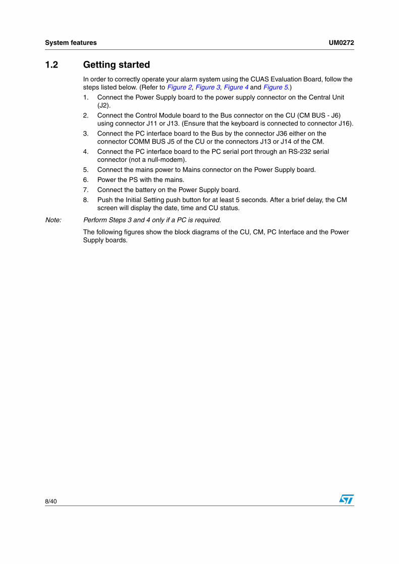
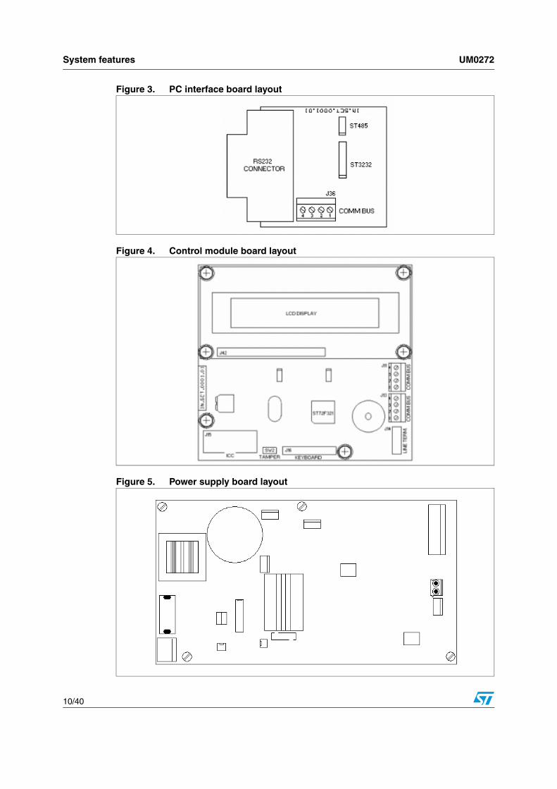
Figure 3. PC interface board layout
Figure 4. Control module board layout
Figure 5. Power supply board layout

UM0272 System parameters
11/40
2 System parameters
2.1 IntroductionSystem parameters can be configured by using either the Control Module or the PC Interface. Using the PC interface provides the advantage of using a user-friendly graphic interface (GUI) to configure the system parameters off-line. Once the system is configured on its own PC, it is possible to download information to the CU. For safety reasons and in order to avoid any tampering from a different installer, a system installation code is required before entering Parameter Setting mode on the CU.
2.2 ZonesEach zone is balanced, meaning that the CU detects any resistance variations on the input line. A certain resistance value is assigned during the installation and when an imbalance is detected, it is considered as an infraction and processed.
In each zone, a resistor can be placed between each zone terminal (i.e. J20 to J24 for the hard-wired zones). In this case, the value of each resistor can be decided by the installer and it is not necessary to set the same value for each zone. Using this feature ensures that any additional resistance values coming from the wiring do not affect system performance.
Each zone can be included or excluded from the control flow (i.e. if a sensor is broken the zone in which it is connected can be temporary excluded), and the working mode can be set either as normally closed (NC or balanced) or normally opened (NO or unbalanced). The zone status variation is immediately stored by the CU when detected, but it is processed only once the delay time associated to the zone is elapsed (if any delay is set).
Each zone can be logically associated to all the others in OR (as default) or in AND modes. In AND mode, status variations are detected and processed by the CU only if all the zones in AND mode have their status changed too. Each zone can be in AND mode with another zone, but the vice versa is not mandatory. For example, Zone 4 can be in AND mode with Zone 5 (Zone 4 is now seen as Group 4), but Zone 5 is not in AND mode with Zone 4 (Zone 5 is associated to Zone 4 in OR mode).
Each zone is protected against negative voltage, over voltage and ESD.
2.3 OutputsEach output behavior can be configured as “change status” (ON for a certain time followed by an OFF period or vice versa) or “toggle status” (each time an alarm condition occurs, the output status is toggled). One or more outputs can be associated to each zone and can be enabled or disabled from the system. The default level of each output can be configured as high or low.
Four outputs are SSR outputs that can supply up to 1A (internally limited) depending on the power supply capacity (connectors J25/J26, J27/J28, J29 and J30). Typically such outputs are dedicated to sirens (self-powered and internal) and for other devices that require power (connectors AUX1 and AUX2).
Two outputs (J32) are transistorized general purpose outputs that can be configured for signaling alarm conditions or the CU status.

System parameters UM0272
12/40
The last output is a micro relay with the NC, C and NO clean contacts available. The maximum voltage and current applicable to the contacts is 0.4A @ 125VAC and 2A @ 30VDC for resistive load and 0.2A @ 125VAC and 1A @ 30VDC for inductive load.
2.4 PartitionsA partition is a logical group of zones with an assigned name and behavior that can be activated or deactivated by an activation device existing on the system (i.e. keyboard, smartcard, etc.). On each partition, it is possible to associate two or more zones present on the system; a single zone may belong to several different partitions.
Zones are associated as inputs or outputs:
● An input association means that when the partition is deactivated by a device (i.e. by a smartcard when entering a protected area) ONLY all the zones associated to the Input will be excluded by the control flow. If any of the zones not associated to the deactivated partition is forced, an alarm condition will be detected and processed.
● An output association means that ONLY the associated zones will be controlled by the CU once the system is activated by a device.
Each partition can be associated to one or more user codes and vice versa. Each time a user enters his code, all the partitions associated to that code can be enabled or disabled even individually.
2.5 Log eventsThe CU automatically records a certain number of events in the internal E2 memory once they occur. The event log feature enables the owner or the installer (not the users) to view the event history using the appropriate menu feature (or, these events can be downloaded through the PC interface and analyzed). The system can record up to 999 events. If more events occur, the oldest ones are automatically replaced by the newest.
2.6 OptionsDuring the installation it is possible to enter Test mode. Test mode enables the installer to test (by watching the signal level associated to the selected zone) zones installed on the system individually or all together once all the sensors are wired on the CU and the zone balanced. The CU automatically stores the balance values after the command is properly sent by the installer to the CU.
In Output Test mode, it is possible to toggle each output level each time the installer presses a key (or when the appropriate command is sent to the CU using the PC GUI). In this way, it is possible to test each device connected to the outputs.
A Module Acquisition feature is available from the Option menu. This feature enables the installer to update the communication bus module address table; adding new modules and removing any deleted modules on the system. Once the update is started, the CU starts scanning for modules and stores all the modules that acknowledge the CU interrogation. Of course, this feature is available only at the service level.
Once an owner or service password is entered, it is possible to enter the system status menu to display the actual status of each zone and output.
UM0272 System hardware configuration
13/40
3 System hardware configuration
3.1 IntroductionThe hardware configuration greatly depends on the area to protect. The CU is very flexible due to its easy way to program each input and output line. It is possible to configure a more powerful system using bus modules to expand the features.
It is possible to manage, for example, two different areas independently or with one or more zones in common; it all depends on how the CU is configured.
Using the GSM module, it is possible to know the CU or the zones status, enable or disable the partitions, or perform several actions on the outputs remotely.
Thanks to the fully configurable outputs, it is possible to decide which device to connect (sirens, external devices, etc.), the activation time, working mode, etc.
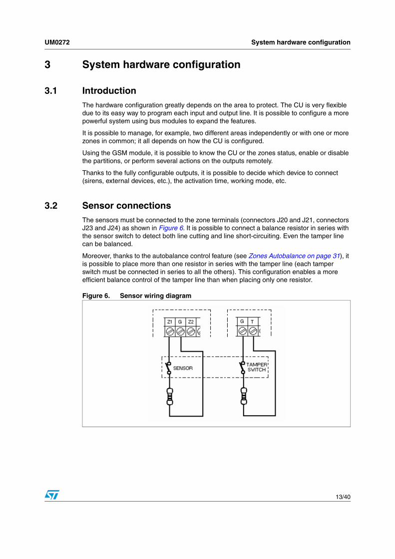
3.2 Sensor connectionsThe sensors must be connected to the zone terminals (connectors J20 and J21, connectors J23 and J24) as shown in Figure 6. It is possible to connect a balance resistor in series with the sensor switch to detect both line cutting and line short-circuiting. Even the tamper line can be balanced.
Moreover, thanks to the autobalance control feature (see Zones Autobalance on page 31), it is possible to place more than one resistor in series with the tamper line (each tamper switch must be connected in series to all the others). This configuration enables a more efficient balance control of the tamper line than when placing only one resistor.
Figure 6. Sensor wiring diagram

System hardware configuration UM0272
14/40
3.3 Control module connectionsEither connectors J11 or J13 can be used to connect the control modules (CM) by wiring the 4 terminals using a twisted and shielded cable. This cable has to be connected to jumper J6 (CM BUS) of the CU.
It is possible to connect up to 8 CMs on the bus line in different ways as shown in Figure 7.
Figure 7. Control module connections
Once the system is powered up, program the CM address for each module installed. Refer to Section 5.7: CM Setup for more information on programming CM addresses. Table 6 lists allowed address ranges.
3.4 Power supply connectionsConnect the power supply cable to jumper J2 of the CU.
3.5 Central unit connectionsTable 1 describes all the CU main board connectors.
The Initial Settings switch is used the first time the system is installed or to completely erase all the setup information. Press this switch for approximately 5 seconds when the CU is completely disabled, to reset all previously programmed parameters (except for the system date and time) with the factory parameters (see Section 4.3: Configuration using the Control Module).

UM0272 System hardware configuration
15/40
3.6 Output connectionsOutput connections are not strictly predetermined enabling a flexible configuration for your system. Certain outputs are best used for siren connections, while others for general purpose devices depending on the required current and device type. Figure 8 shows a typical siren connection that takes into account different types of both internal and external sirens.
Certain external sirens require a third terminal (V) in addition to the power supply (also used to charge the backup battery). In this case, connect the siren power terminals to the SIR AAx connectors; the "+" terminal with Clamp 3 and the "-" terminal with Clamp 1 (permanently connected to +13.8VDC), and the terminal V with Clamp 2. Only Clamp 2 is programmable using the CU setup (see Section 5.6.2: Outputs) in either normally high
Table 1. CU connectors
Ref. Name Description
J1 RF-Board Not used in this version
J2 Power Supply Power Supply connector
J3 Line Term Line termination device (if needed)
J4 ICC Connector ICC Connector for microcontroller programming
J5 Comm Bus BUS connector for modules
J6 CM Bus BUS connector for the CM
J7 I/O Expansion BUS connector for I/O Expansion Module (is the same as the J5 and J6 connectors)
J8 GSM Connector for the GSM module (not for this version)
LS2 Buzzer Connector for the CU buzzer
N/A Speaker Not used in this version
J20/21 and J23/24 Zones Connectors for the sensors
J22 Fire Fire sensor connector
J25 SIR AA1SSR Output. Normally used for the external siren (with the backup battery)
J26 SIR AA2Connected in parallel with J25 (for the connection of two sirens in parallel)
J27 SINT 1 SSR Output. Normally used for the internal siren
J28 SINT 2Connected in parallel with J27 (for the connection of two internal sirens in parallel)
J29 AUX 1 SSR Output. Can be used for sirens or other devices.
J30 AUX 2 SSR Output. Can be used for sirens or other devices.
J32 STS/ALM Transistorized outputs
J35 EXT. WDT EN. Not used in this version.
J37 TMPR Tamper Line Connector
J39, J40 and J41 12VDC Power supply for sensors

System hardware configuration UM0272
16/40
(typical setting for the sirens) or normally low voltage levels. Refer to Table 7 for the correspondence between the output number and the board layout label.
Figure 8. Siren connection
Outputs AUX 1 and AUX 2 from the solid state relay can be used to connect external devices and are fully programmable.
As shown in Figure 9, there are two other fully programmable outputs (transistorized) that include one more option allowing to configure the STS output as a CU status output.
The value of the STS output depends on the CU status (enabled/disabled) and the ALM output as an alarm output where the value of the ALM output changes each time there is an alarm condition.
Note: In the current version, outputs STS and ALM can be configured as a normal output. The current software version does not manage the alarm and CU status signaling.
Figure 9. Status/alarm connector
3.7 Tamper lineThis option is not implemented in this version.

UM0272 Configuring system parameters
17/40
4 Configuring system parameters
4.1 IntroductionThe system can be configured in one of two ways:
● using the PC GUI
● using the Control Module
The system is configured by entering Setup mode; this is possible only if the Central Unit (CU) is in Idle mode (CU disabled).
During the first installation or each time a new module is installed or removed from the system, the connected modules must be registered in the CU memory. When using the PC GUI, the software automatically registers connected modules in the CU memory. When using the Control Module, follow the instructions provided in Section 4.3: Configuration using the Control Module.
4.2 Configuration using the PC GUIThis feature is not implemented in this version.
4.3 Configuration using the Control ModuleAt first installation, communication with the CM is impossible since no modules are registered in the CU memory. For this reason (or each time a new module is installed or removed from the system), press the Initial Setting button on the CU board for approximately 5 seconds. The CU scans the bus and registers all the modules installed on it. Once this procedure is successfully completed, the CM displays the system date/time and the CU status (OFF) as shown in Figure 10.
Figure 10. Central unit connected message
Note: Pressing the Initial Setting button resets all the system settings on the CU to their factory settings (except for the system date and time).

Configuring system parameters UM0272
18/40
Figure 11 describes the various key functions. In some cases, the same button has different function in a different context.
Figure 11. Control module keypad
4.4 Password protectionIn order to perform any operation, password identification is required. The system is organized with three password security levels. Press any key on the CM keypad to access the password menu.
The service and the owner passwords must be different from each other because the CU automatically recognizes the access level by the password. It is possible (but not recommended) to use the same Owner (or Service) password as one of the User passwords. All the User passwords must be different.
Table 2. Password protection for each access level
Level Description
ServiceThe service level is dedicated to system installation. All CU parameters are accessible and modifiable and passwords can be setup. The CU cannot be enabled or disabled when accessing this level.
OwnerThis level is normally assigned to the protected ambient owner. Only parameters that do not affect the hardware configuration are accessible (i.e. the zone timing, output association, etc.). The CU cannot be enabled or disabled when accessing this level.
UserThis level switches ON/OFF the CU and available partitions. It is impossible to modify or display parameters.

UM0272 Configuring system parameters
19/40
4.5 Access levelsThree access levels are available: Service, Owner and User as described in Table 2.
The CM only displays certain menus for each access level.
Note: The CU automatically recognizes the access level by the password.
4.5.1 User level
After entering a User password, the CM displays the User menus as shown in Figure 12. Use the Control Module sub-menu in the Bus Module parameter setting menu to define User access rights (Control Module on page 33).
Figure 12. User level menus
4.5.2 Service and owner levels (S/O-L)
The default service password is 000000 and the owner password is 000001. All passwords can be changed through the Setup menu (see Section 5.6.5: Access code).
After entering a Service (or Owner) password, the CM displays the Service/Owner menus as shown in Figure 13. Four menus (System Status, Log Event, Setup and CM Setup) are available by pressing the correspondent menu number.
Table 3. Menus available by access level
Menu User Owner Service
System Enable/Disable ✗
Partition Enable/Disable ✗
Partition Select ✗
System Status ✗ ✗
Log Event ✗ ✗
Setup ✗ (1)
1. Certain limitations apply. See Section 5.6: Setup on page 24.
✗
CM Setup ✗ ✗

Configuring system parameters UM0272
20/40
Figure 13. Service / owner level menus
In order to return to the previous menu, press EXIT (in any menu).

UM0272 Menus
21/40
5 Menus
5.1 Using the key padTo navigate between the different parameter settings of each sub-menu, press the keys. When the required parameter is displayed, press ENT to display its value. Press EXIT to return to the Setup menu, or press ENT again to modify the parameter setting.
Before entering in a specific option, it is possible to change the line number (zone, option, partition, etc.) by pressing the key (the line number is incremented by 1), in this way it is possible to change a specific parameter (as, for example, the line status) for all the lines without entering each time the line number.
Text entry is similar to that of a cellular phone for SMS messaging; each numeric key has an associated text character (Figure 14). By pressing repeatedly (within a short time) a digit, each associated character is scrolled.
Figure 14. Text entry
Leave the digit key button or press a different key (for a different character) when the required character is displayed.
Press the CLR key to erase the entire written string. Use the keys to select a single character. Press ENT again to save the description.
Press to switch between uppercase and lowercase characters. Table 5 lists all character associations.
5.2 System Enable/DisableOnce a user enters a valid access code (password), the CM displays the System Enable/Disable menu. Use this menu to enable or disable the alarm system.
5.3 Partition Enable/SelectThe Partition Enable menu enables the user to switch ON/OFF all the partitions associated to his user access code or to continue and individually select the associated partitions (only partitions associated to the user’s access code are available).

Menus UM0272
22/40
In the example shown in Figure 15, the entered access code has only 4 associated partitions (00, 02, 05 and 06). Use the keys to display the available partitions and press ENT to associate/dissociate the displayed partition (the symbol will change from a dot to a cross and vice versa). Press to display the next group of partitions (if available).
Figure 15. Partition selection
Press EXIT to validate the partition selection values.
5.4 System status Press 1 to open the System Status menu that displays the status of the inputs and the outputs present on the system. Press 1 again to display the Input menu and the status of Zone 0 is as shown in the example in Figure 16.
Figure 16. System status menu
The CM screen displays the zone number, zone value (active or not-active, depending on the zone setting and the actual balance status), zone status (enabled or disabled) and the first 11 characters of the description.
To display the status of the next zone, press . It is also possible to select a specific zone number (starting the scroll from this point forward); press ENT, enter the desired zone number and then press ENT again.
5.5 Log eventUse the Log Event menu (Figure 17) to display all events stored in the internal memory of the CU when they occur.
The log capability goes up to 1000 events (0 based). Once the last log location is reached, new events overwrite the oldest events.

UM0272 Menus
23/40
Press ENT button to enter directly an event number, or use the keys to scroll through log events.
For each event, the CM displays the event description, the occurred time and date and the flag value (for the events that can have the same description but a different status).
Figure 17. Log event menu

Menus UM0272
24/40
5.6 SetupThe Setup menu enables the installer (and with certain limitations, the owner) to set up all CU parameters (Figure 18).
To enter the Setup section, press 3 to display the first sub menu. To display the other sub menus, press or directly enter the sub-menu number.
Press EXIT to return to the previous menu.
Note: Setup mode is available only when the CU is in Idle mode (disabled).
Figure 18. Setup menu
5.6.1 Zones
The Zones sub-menu enables the service provider or owner to modify zone parameters. Press the 0 key to enter the Zones sub-menu and display the zone number prompt. Enter a zone number to display the zone options. Figure 19 shows the Zone option sub-menus.

UM0272 Menus
25/40
Figure 19. Zone setting menus
Description
The Zone description is 16 characters long and is displayed on the System Status (Section 5.4: System status) and Log Event (see Section 5.5: Log event) menus. This displays a more significant name rather than a number. To change the description, press ENT, enter the new text and press ENT again to store the new description.
Status
The Status sub-menu adds or removes the selected zone from the control flow. Once disabled, the zone is no longer under control, even if included in an enabled partition.
This option is used for disabling the zone if it is not used, if a sensor connected on it is broken (waiting for a replacement) or to temporarily disable the zone without losing any settings. Press ENT to switch between the two possible values (enabled/disabled).
Input time
The input time is delay between the detection of an alarm condition and the triggering of the associated outputs. Normally this time is assigned to zones that protect the area (and the

Menus UM0272
26/40
path) where the CU insertion device (keyboard, smartcard device, etc.) is installed. The alarm condition is immediately stored, but is processed only once the input time is elapsed.
To change the input time, press ENT; the minutes will be changed first and the seconds immediately after. Press ENT to store the new values. If the input time is set to 0 minutes and 0 seconds, the zone will be considered as instantaneous in input. The input time can be set from 00:00 to 59:59 (mm:ss).
Output time
As with the input time, it is possible to associate an output time in order to allow authorized personnel to leave the protected area once enabled the CU.
The time is set as described in Input time.
Working mode
The Working mode indicates the way the CU detects an alarm condition. The following Working mode values are possible:
● Normally opened: The zone is normally unbalanced from its stored value (see Outputs Test on page 32). Once the zone is balanced, the CU processes the alarm condition (after an input or output time, if set).
● Normally closed: The zone is normally balanced and an alarm is processed when an unbalanced state is detected.
● Change: This is a mixed working mode where the CU process an alarm condition each time a different value from the previous one is detected (unbalanced if the zone is balanced and vice versa). Once the alarm is processed, the CU considers the new zone status as the normal one. Press ENT to switch between the different working modes.
● Beeper signal: This feature triggers a buzzer when an installed control module detects an alarm condition in the zone. Press ENT to switch between enabled/disabled. (Not included in this version.)
● Filter: The zone filter enables the CU to detect an alarm condition only after a certain time (the counter is reset once the filter time is elapsed). As shown in Figure 20, press ENT to first modify the number of pulses (zone value changes), up to 999 pulses can be programmed, and the time within which the pulses must occur (mmss). (Not included in this version.)
Note: The Working mode for inputs is always normally closed. The option for changing the Working mode is already implemented but has no effect in this release.

UM0272 Menus
27/40
Figure 20. Zone filter menu
● Outp. associated: This function associates one of the installed outputs to the selected zone. Once the zone alarm condition is processed, the corresponding outputs are triggered.
Press ENT to display the output associated menu (Figure 21) and the first 8 outputs hardwired on the CU. If more outputs are present on the system by means of one or more IO Expanders, press to display the next group of 8 outputs. Press to scroll through each displayed output. In order to associate the pointed output, press ENT. The symbol displayed after the output number will change from a dot (.) to a plus sign (+).
See Chapter 5.6.2 for possible output configurations.
Figure 21. Output associated menu
● AND association: This feature allows the installer to logically regroup the selected zone to one or more of the other zones installed on the system. If a zone is in AND mode with another zone, the CU will detect an alarm condition only if all the other zones associated in AND mode detect an alarm condition also. This feature can be useful, for example, in a corridor where two sensors are installed; the alarm condition is processed only if an infraction is detected in one direction but not the other. The AND association menu is similar to the output association menu.
5.6.2 Outputs
The Output settings menu (Figure 22) is used to configure both the outputs hardwired on the CU and those installed by means of the IO Expander present on the system (if installed).

Menus UM0272
28/40
Figure 22. Output settings menus
Description
The Output description is 16 characters long and is displayed on the System Status (Section 5.4: System status) and Log Event (see Section 5.5: Log event) menus. This displays a more significant name rather than a number. To change the description, press ENT, enter the new text and press ENT again to store the new description.
Status
The Status sub-menu adds or removes the selected output from the control flow. Once disabled, the output will not be activated by the CU even if associated to a zone where an alarm condition is detected.
This option is used for disabling the output if it is not used, if a sensor connected on it is broken (waiting for a replacement) or to temporarily disable the output without losing any settings. Press ENT to switch between the two possible values (enabled/disabled).
Working mode
The Working mode indicates the way the output is managed once enabled and associated to a zone. The possible working mode values are the following:
● Change Status: The CU changes the output value during an alarm condition and restores the previous value once the time associated to the output is elapsed.
● Toggle: The CU toggles the output value each time it detects an alarm condition. In order to switch between the different working modes, press ENT.
● Default Level: The default level can be normally high (the SSR outputs and the transistorized outputs are at 12 VDC level, the Relay will close the contacts between the C and NA terminals, the Buzzer is normally activated) or normally low (the opposite

UM0272 Menus
29/40
condition). In order to switch between the different default levels, press ENT; the output will immediately change its value.
● Timing: The output time is the time that the output remains active (the active status depends on the default level setting) when the CU processes an alarm condition. Press ENT to display the menu shown in Figure 23. Press ENT again and the cursor will underline the hour field. Press ENT again to save the Hour value and pass to the minutes field, and finally to the seconds field. The maximum time allowed is 11h 59m 59s.
Figure 23. Output timing menu
5.6.3 Partitions
Partition menus (Figure 24) are used to configure partitions which are logical groups of zones. Each time a partition is activated by an activation code (see Section 5.6.9: Bus modules), all associated zones are controlled by the CU to detect an alarm condition (infraction). Alarm conditions in inactive partitions are ignored and not processed (even when detected) by the CU.
Partitions are associated to zones both in input and in output. The input association is the group of zones that will be removed from the control flow of the CU once this partition is disabled by any activation code (normally when entering the protected area). The output association is the group of zones controlled (and processed when an alarm condition is detected) by the CU when leaving the protected area.
Figure 24. Partition menus

Menus UM0272
30/40
Description
The Partitions description is 16 characters long and is displayed on the Log Event (see Section 5.5: Log event) menus. This displays a more significant name rather than a number. To change the description, press ENT, enter the new text and press ENT again to store the new description.
Input
The Input sub-menu associates the selected partition to one or more zones installed on the system. Press ENT to display the association menu (Figure 25) and the first 8 zones hardwired on the CU. If more zones are present on the system by means of one or more IO Expander, press to display the next group of 8 zones. Press to scroll through each displayed zone. To associate the partition to selected zone, press ENT. The symbol displayed after the zone number will change from a dot (.) to a plus sign (+).
Output
Similar to the Input sub-menu, this sub-menu associates partitions and zones that will be monitored once the selected partition is activated.
Figure 25. Input and output association menu
5.6.4 Installation code
For security reasons, an installation code is required to enter the CU in Setup mode using any programming device (either a Control Module or the PC GUI). The factory value (both for the CU and the CM) for the installation code is 00000000.
Changing the installation code from this menu affects both the installation code of the CU of the CM programming the CU. If more than one CM is installed on the system, the old installation code must be changed manually for each module. See Section 5.7: CM Setup for more information about changing the installation code for Control Modules.
Figure 26. Installation code menu

UM0272 Menus
31/40
Press ENT to display the current installation code (Figure 26). Press ENT again to modify the installation code.
Note: The CU installation code is displayed in clear and not encrypted with the star symbol (*) as this menu is only available in Setup mode; the correct password to access the Service level must have previously been entered.
5.6.5 Access code
The access code is required to enter the CU Setup mode.
● If an Owner (access level) password is entered, the menu shows the current code. Press ENT to enter the new code.
● If a Service (access level) password is entered, the menu shows the current code. Press ENT to enter the new code. Press ENT to define the code as the Service or Owner code. Both the owner and the service codes can be modified at this access level.
After having entered the new code, press ENT to save the new code. At the prompt, press the 7 key to confirm the new code.
5.6.6 Options
The Options menu sets the parameters of several CU features. Four Option sub-menus are available (Figure 27). Press the corresponding number to enter the selected sub-menu.
Figure 27. Option menus
Zones Autobalance
The Zone Automatic Balance sub-menu memorizes the zones balance values once the installer has installed the balance resistors on the sensor lines. When using this system, a resistor (Figure 6) without a predetermined value can be used to balance the line. Of course, if a line balance control is not used, this resistor can be omitted. Once all the resistors are installed, press the 1 key to store the all the balance resistor values in the CU.
Once the Zones Autobalance feature is enabled, any variation of the resistance triggers an alarm condition and is processed by the CU.

Menus UM0272
32/40
Zones Test
Two different tests are available in the Zones Test sub-menu:
● single zone test that displays the signal level of the selected zone (depending on the value of the installed resistors)
● a multiple zone test that displays the status (balanced/unbalanced) of groups of 8 zones (see Figure 28). Press to scroll to the next group of 8 zones (if installed on the system). A dot (.) indicates a balanced zone, while a plus sign (+) indicates an unbalanced zone.
Figure 28. Zones testing
Outputs Test
Similar to the Zones Test, it is possible to test each output. Select Outputs Test to display the status of groups of 8 outputs (installed on the system). Press to scroll to the next group of 8 outputs. Press to select an output. Press ENT to change the status of the selected output.
Modules Acquisition
The Modules Acquisition feature is used when one or more modules are removed from the system, or when the installer wants to update the bus configuration. When this feature is selected, the CU erases all the modules stored into the internal memory, and starts scanning the bus. Each module that responds to the CU is stored into the CU modules table.
5.6.7 Timer events
This option is not yet implemented.
5.6.8 Date and time
This sub-menu (Figure 29) is used to modify the system date and time. When this sub-menu is selected, both the date and the time have to be modified (reset). Press ENT to modify the date and time values. The cursor starts to blink on the first digit of the month. Enter the correct value and then press ENT in order to modify the day, year, hours and minutes.

UM0272 Menus
33/40
Figure 29. System date and time
5.6.9 Bus modules
The Bus Modules menu (Figure 30) sets up the modules installed on the system. Once installed, a module address must be stored in the CU address table using the procedure described in Modules Acquisition on page 32.
Note: This procedure can only be executed once all the modules are wired on the bus line.
Figure 30. Bus modules menu
Control Module
As shown in Figure 31, there are three options associated to the CM:
● Address: This is the CM address set by the procedure described in Section 5.7: CM Setup. In this sub-menu, the Address menu is read-only.
● Description: This is the CM description (16 characters long). Press ENT to modify the description.
● User management: Each CM is also a CU ON/OFF device used to activate or deactivate the unit using a password from a given user.

Menus UM0272
34/40
Figure 31. Control module menus
Each CM is able to manage up to 8 users, numbered from 0 to 7. Press ENT to display the user number selection prompt. After inserting the required user number, three options are available as shown in Figure 32.
Figure 32. User management menu
1. User name: a 16 character field associated to each user. This name is the one recorded in the log event.
2. Access code: the code associated to the selected user. This code is used to switch ON/OFF the CU.
Note: As this code is automatically recognized by the CU, it must be unique, meaning different from all other user codes and from the service and owner codes.
3. Partition: each code has to be associated to one or more partition. Only these partitions (and consequently only all the zones associated to these partitions) will be processed when the CM detects an alarm condition. Press ENT to select the partitions to associate (Figure 33). Use the keys to select the desired partition, press ENT to associate/dissociate the partition (the symbol will change from a dot (.) to a plus sign (+) and vice versa) and the key for selecting the next group of partitions.

UM0272 Menus
35/40
Figure 33. Partition association menu
GSM Module
This feature is not implemented in this version.
I/O Expander
The Input/Output Expander module is used to add zones and outputs. Although this module is not fully managed in this version, certain options are available (Figure 34).
● Address: the I/O expander address set by the jumpers on the I/O expander module board. The Address menu is read-only.
● Description: the I/O Expander description (16 characters long). Press ENT to modify the description.
Figure 34. I/O Expander menu
Card Reader
This feature is not implemented in this version. The module address and description are the only menus available.
Keypad
This feature is not implemented in this version. The module address and description are the only menus available.
RFID Key
This feature is not implemented in this version. The module address and description are the only menus available.

Menus UM0272
36/40
5.6.10 Central Unit
The Central Unit menu displays CU serial number. Press any key to return to the previous menu.
5.7 CM SetupThe CM setup menu (Figure 35) is used to set the current CM address and to modify the installation code.
Figure 35. Control module setup menu
Press 1 to display the current CM address. Press ENT to modify the address. This value must be entered when installing the system, in order to assign a valid CM address before storing the CU address (see Modules Acquisition on page 32) or when a new CM is added on the bus.
Press 2 to display or modify the installation code. This must be performed when installing the system and each time a new CM is installed on the BUS. Press ENT to modify the installation code. This code must match the one programmed on the CU (00000000 by default), otherwise the setup procedure is impossible (see Section 5.6.4: Installation code).
UM0272 Electrical characteristics
37/40
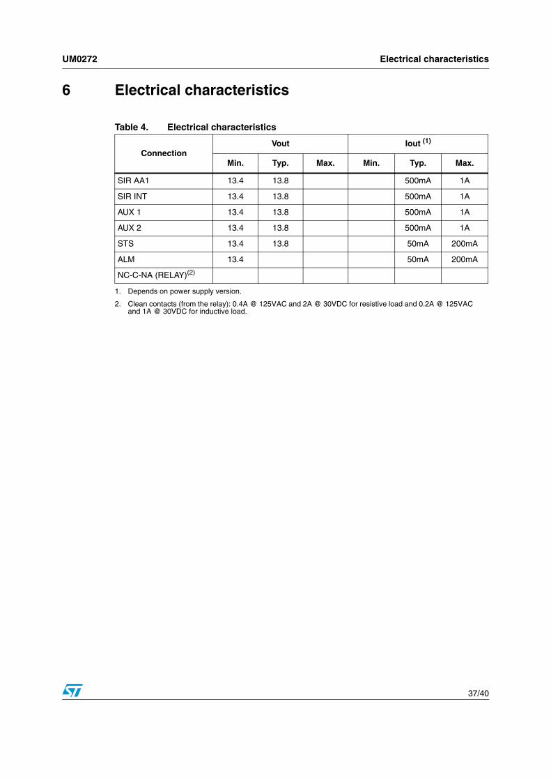
6 Electrical characteristics
Table 4. Electrical characteristics
ConnectionVout Iout (1)
1. Depends on power supply version.
Min. Typ. Max. Min. Typ. Max.
SIR AA1 13.4 13.8 500mA 1A
SIR INT 13.4 13.8 500mA 1A
AUX 1 13.4 13.8 500mA 1A
AUX 2 13.4 13.8 500mA 1A
STS 13.4 13.8 50mA 200mA
ALM 13.4 50mA 200mA
NC-C-NA (RELAY)(2)
2. Clean contacts (from the relay): 0.4A @ 125VAC and 2A @ 30VDC for resistive load and 0.2A @ 125VAC and 1A @ 30VDC for inductive load.

Miscellaneous UM0272
38/40
Appendix A Miscellaneous
A.1 Keyboard character association
A.2 Module address ranges
A.3 Output assignments
Table 5. List of available characters
Key Character Sequence
0 A B C 0 a b c
1 D E F 1 d e f
2 G H I 2 g h i
3 J K L 3 j k l
4 M N O 4 m n o
5 P Q R 5 p q r
6 S T U 6 s t u
7 V W X 7 v w x
8 Y Z 8 y z .
9 [SPACE] 9 * - + / '
Table 6. List of possible module addresses
Address Range Bus Module
0 Reserved
1 to 8 Control module
9 to 16 Keypad
17 to 24 RFID reader
25 to 32 Card reader
33 to 40 I/O expander
Table 7. Output assignments
Output No. Board Layout Label
0 SIR AA1
1 SIR INT
2 AUX 1
3 AUX 2
4 STS
5 ALM
6 NC-C-NA (RELAY)
7 Not used in this version

UM0272 Revision history
39/40
Revision history
Table 8. Document revision history
Date Revision Changes
19-Sept-2006 1 Initial release.

UM0272
40/40
Please Read Carefully:
Information in this document is provided solely in connection with ST products. STMicroelectronics NV and its subsidiaries (“ST”) reserve theright to make changes, corrections, modifications or improvements, to this document, and the products and services described herein at anytime, without notice.
All ST products are sold pursuant to ST’s terms and conditions of sale.
Purchasers are solely responsible for the choice, selection and use of the ST products and services described herein, and ST assumes noliability whatsoever relating to the choice, selection or use of the ST products and services described herein.
No license, express or implied, by estoppel or otherwise, to any intellectual property rights is granted under this document. If any part of thisdocument refers to any third party products or services it shall not be deemed a license grant by ST for the use of such third party productsor services, or any intellectual property contained therein or considered as a warranty covering the use in any manner whatsoever of suchthird party products or services or any intellectual property contained therein.
UNLESS OTHERWISE SET FORTH IN ST’S TERMS AND CONDITIONS OF SALE ST DISCLAIMS ANY EXPRESS OR IMPLIEDWARRANTY WITH RESPECT TO THE USE AND/OR SALE OF ST PRODUCTS INCLUDING WITHOUT LIMITATION IMPLIEDWARRANTIES OF MERCHANTABILITY, FITNESS FOR A PARTICULAR PURPOSE (AND THEIR EQUIVALENTS UNDER THE LAWSOF ANY JURISDICTION), OR INFRINGEMENT OF ANY PATENT, COPYRIGHT OR OTHER INTELLECTUAL PROPERTY RIGHT.
UNLESS EXPRESSLY APPROVED IN WRITING BY AN AUTHORIZED ST REPRESENTATIVE, ST PRODUCTS ARE NOTRECOMMENDED, AUTHORIZED OR WARRANTED FOR USE IN MILITARY, AIR CRAFT, SPACE, LIFE SAVING, OR LIFE SUSTAININGAPPLICATIONS, NOR IN PRODUCTS OR SYSTEMS WHERE FAILURE OR MALFUNCTION MAY RESULT IN PERSONAL INJURY,DEATH, OR SEVERE PROPERTY OR ENVIRONMENTAL DAMAGE. ST PRODUCTS WHICH ARE NOT SPECIFIED AS "AUTOMOTIVEGRADE" MAY ONLY BE USED IN AUTOMOTIVE APPLICATIONS AT USER’S OWN RISK.
Resale of ST products with provisions different from the statements and/or technical features set forth in this document shall immediately voidany warranty granted by ST for the ST product or service described herein and shall not create or extend in any manner whatsoever, anyliability of ST.
ST and the ST logo are trademarks or registered trademarks of ST in various countries.
Information in this document supersedes and replaces all information previously supplied.
The ST logo is a registered trademark of STMicroelectronics. All other names are the property of their respective owners.
© 2006 STMicroelectronics - All rights reserved
STMicroelectronics group of companies
Australia - Belgium - Brazil - Canada - China - Czech Republic - Finland - France - Germany - Hong Kong - India - Israel - Italy - Japan - Malaysia - Malta - Morocco - Singapore - Spain - Sweden - Switzerland - United Kingdom - United States of America
www.st.com