central plumbing contracting alexandria nsw 2015 t: 9699
TRANSCRIPT
Central Plumbing ContractingSuite WGA, Ground Floor, 75-85 O’Riordan St
Alexandria NSW 2015T: 9699 2722
C:\Users\paps422\Desktop\SY180115_RCR_IASB_HYD_WMR_Rev G.docx Page 1 of 18
RANDWICK CAMPUSREDEVELOPMENT –Integrated ASB (IASB)AdditionState Significant Development Application
Integrated Water Management PlanHYDRAULIC SERVICES
Prepared by:
Central Plumbing Contracting
Central Plumbing Project Reference - SY180115

C:\Users\paps422\Desktop\SY180115_RCR_IASB_HYD_WMR_Rev G.docx Page 2 of 18
Disclaimer
This report has been prepared in accordance with the scope of services described in the contractor agreement between Central Plumbing Contracting and the Client. The report relies upon data,surveys, measurements and results taken at or under the particular terms and conditions specifiedherein. Changes to circumstances or facts after certain information or material has been submittedmay impact on the accuracy, completeness or currency of the information or material. This reporthas been prepared solely for use by the Client, Central Plumbing Contracting accepts noresponsibility for its use by other parties without the specific authorisation of Central PlumbingContracting. Central Plumbing Contracting reserves the right to alter, amend, discontinue, varyor otherwise change any information, material or service at any time without subsequentnotification. All access to, or use of, the information or material is at the user's risk and CentralPlumbing Contracting accepts no responsibility for the results of any actions taken on the basis ofinformation or material provided, nor for its accuracy, completeness or currency.
REVISIONS
Revision Date Purpose Prepared By Approved ByA 10/05/2019 Draft Issue for LL review Rhys Edwards
B 11/06/2019 Draft Issue for LL Approval Rhys Edwards
C 04/07/2019 Issue for SSDA Rhys Edwards P.Johnson
D 11/07/2019 Issue for SSDA Rhys Edwards P.Johnson
E 16/07/2019 Issue for SSDA Rhys Edwards P.Johnson
F 05/08/2019 Issue for ISSDA Rhys Edwards P.Johnson
G 12/08/2019 Issue for ISSDA Rhys Edwards P.Johnson
Unless otherwise advised, the parties who have undertaken the Review and Endorsement confirm that the informationcontained in this document adequately describes the conditions of the site located at Magill St, Randwick, NSW, 2031.
COPYRIGHT
No part of this document may be reproduced, adapted, transmitted or stored in a retrieval system in any form or by anymeans without written permission unless otherwise permitted under the Copyright Act, 1968. Enquiries should beaddressed to Central Plumbing Contracting.
© Central Plumbing Contracting
All intellectual property and copyright reserved.
C:\Users\paps422\Desktop\SY180115_RCR_IASB_HYD_WMR_Rev G.docx Page 3 of 18
Table of Contents
1 Executive Summary .........................................................................................4
2 Key Design and Performance Principles ..........................................................4
2.1 Standards and Codes .........................................................................5
2.2 AUSHFG ............................................................................................5
2.3 Relevant Authorities ...........................................................................5
3 The Development Site .....................................................................................6
3.1 Design Standards ...............................................................................6
4 Outline of Proposed Water Management Systems ...........................................7
4.1 Potable Water ....................................................................................7
4.2 Fire Hydrants and Fire Sprinklers .......................................................7
4.3 Sanitary Plumbing and Drainage ........................................................7
4.4 Roofwater Plumbing and Drainage .....................................................8
4.5 Domestic Potable Hot Water ..............................................................8
4.6 Non-Potable water .............................................................................9
5 Advantages and Disadvantages.......................................................................9
5.1 Advantages of Current Design ...........................................................9
5.2 Disadvantages of Current Design .......................................................9
6 Fixtures, Fittings and Tapware .......................................................................10
7 ESD Initiatives ...............................................................................................10
Appendices
Appendix A - Sydney Water Pressure and Flow Information ........................................11
Appendix B - Hydraulic Services Reference Drawings .................................................12
Appendix C - Site Plan ................................................................................................14
Appendix D - Potable Water Supply Schematic ...........................................................15
Appendix E - Sanitary Plumbing Schematic .................................................................16
Appendix F - Stormwater Schematic............................................................................17
Appendix G - Hot Water Schematic .............................................................................18

C:\Users\paps422\Desktop\SY180115_RCR_IASB_HYD_WMR_Rev G.docx Page 4 of 18
1 Executive SummaryThis Integrated Water Management Plan (IWMP) addresses waste water and potable water systems for theproposed Integrated ASB Addition, as an addendum to the Integrated Water Management Plan previouslysubmitted under SSD 9113 Prince of Wales Expansion. The content of this report relates on to the additionalcore scope elements of the Integrated ASB Addition (IASB).
This report is based on item 14 of the Secretary’s Environmental Assessment Requirements (SEARs) for theState Significant Development Application (SSDA) and the associated Hydraulic Services design drawings,Health Infrastructure NSW (HI) briefing documents and subsequent ancillary information provided.
Scope of services covered within the plan include:
¡ sanitary and trade waste discharge
¡ roof water plumbing and drainage systems connecting to existing civil trunk stormwater
¡ domestic potable water supply systems
Hydraulic services of the IWMP can be summarised as follows:
¡ Consultation with relevant utility supply agencies has been conducted to verify the condition, capacity,compliance, reliability and efficiency of the existing sewer and water mains infrastructure and havefound them to be acceptable for connection
¡ Sewer and trade waste water from the site to discharge to Sydney Water’s sewer main via proposedinternal ‘house drainage’ system in accordance with AS.3500: 2015 and Sydney Water’s requirements
¡ Water pressure/flow results was obtained from Sydney Water (Refer to Appendix ‘A’ of this plan)
¡ Water supply provided will be in accordance with Australian Drinking Water Guidelines (2011, updated2016, version 3.4)
¡ Rainwater from roof areas will be collected, stored and re-used for landscape irrigation purposes only
¡ Roofwater will drain/discharge through a series of rainwater outlets and eaves gutters systems designedin accordance with AS.3500: 2015
¡ Ecological Sustainable Development (ESD) principles as nominated in this plan will be incorporated intothe designs and the construction of the facility
2 Key Design and Performance PrinciplesA major element of this IWMP is to outline the minimum building services design criteria to delivercompliance with HI guidelines, NSW Department of Health Engineering guidelines, Prince of Wales Hospitaland UNSW briefing documents, user groups and all relevant statutory authority requirements, so that themost cost effective and energy efficient, maintainable solutions are achieved for the Project, with patient careand safety the main priority.

C:\Users\paps422\Desktop\SY180115_RCR_IASB_HYD_WMR_Rev G.docx Page 5 of 18
This IWMP is to be read in conjunction with the Hydraulic Services design drawings (Refer to Appendix ‘B’ ofthis plan), for full list of available hydraulic services drawings, which include:
¡ Building code compliance
¡ HI requirements
¡ Effective use and waste minimisation of limited water resource
¡ Authority infrastructure availability and capacity
¡ ESD principles
The hydraulic services systems currently documented will:
¡ Ensure the safety of building occupants and patients
¡ Minimise water wastage
¡ Minimise initial capital cost and ongoing maintenance and energy costs
¡ Ensure effective use of energy and resources
2.1 Standards and CodesThis plan has used the following Australian Standards and Codes as references:
¡ National Construction Code (NCC) – 2016 (being the current version at the time of writing this report)
¡ Building Code 2016
¡ AS 3500 Plumbing and Drainage Suite of standards – 2015 as ratified by the NCC
¡ AS 2419.1 Fire Hydrant Installations – 2005
¡ AS 2118.1 Fire Sprinkler Installations – 1999
¡ AS2118.6 Combined Sprinkler and hydrant systems - 2012
2.2 AUSHFG¡ Australasian Health Facilities Guidelines (AUSHFG) Parts A - F
¡ Hospital acquired infections – Engineering down the risk – Handbook – HB 260 – 2003
2.3 Relevant AuthoritiesKey authorities directly relating to the hydraulic and fire services design are (please see Table 1 below):
Table 1 Utility Authorities
Authority Asset
Sydney Water Water Supply / Sewer Drainage
Jemena Gas Natural Gas supply and reticulation
NSW Fire and Rescue Regulator for fire hydrants and automatic fire sprinklers
Randwick City Council Stormwater Civil Drainage
C:\Users\paps422\Desktop\SY180115_RCR_IASB_HYD_WMR_Rev G.docx Page 6 of 18
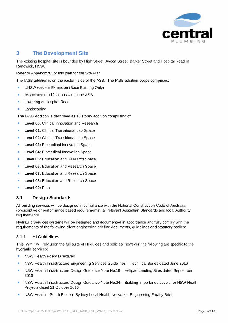
3 The Development SiteThe existing hospital site is bounded by High Street, Avoca Street, Barker Street and Hospital Road inRandwick, NSW.
Refer to Appendix ‘C’ of this plan for the Site Plan.
The IASB addition is on the eastern side of the ASB. The IASB addition scope comprises:
¡ UNSW eastern Extension (Base Building Only)
¡ Associated modifications within the ASB
¡ Lowering of Hospital Road
¡ Landscaping
The IASB Addition is described as 10 storey addition comprising of:
¡ Level 00: Clinical Innovation and Research
¡ Level 01: Clinical Transitional Lab Space
¡ Level 02: Clinical Transitional Lab Space
¡ Level 03: Biomedical Innovation Space
¡ Level 04: Biomedical Innovation Space
¡ Level 05: Education and Research Space
¡ Level 06: Education and Research Space
¡ Level 07: Education and Research Space
¡ Level 08: Education and Research Space
¡ Level 09: Plant
3.1 Design StandardsAll building services will be designed in compliance with the National Construction Code of Australia(prescriptive or performance based requirements), all relevant Australian Standards and local Authorityrequirements.
Hydraulic Services systems will be designed and documented in accordance and fully comply with therequirements of the following client engineering briefing documents, guidelines and statutory bodies:
3.1.1 HI GuidelinesThis IWMP will rely upon the full suite of HI guides and policies; however, the following are specific to thehydraulic services:
¡ NSW Health Policy Directives
¡ NSW Health Infrastructure Engineering Services Guidelines – Technical Series dated June 2016
¡ NSW Health Infrastructure Design Guidance Note No.19 – Helipad Landing Sites dated September2016
¡ NSW Health Infrastructure Design Guidance Note No.24 – Building Importance Levels for NSW HeathProjects dated 21 October 2016
¡ NSW Health – South Eastern Sydney Local Health Network – Engineering Facility Brief

C:\Users\paps422\Desktop\SY180115_RCR_IASB_HYD_WMR_Rev G.docx Page 7 of 18
3.1.2 Regulatory Bodies:¡ Department of Energy, Utilities and Sustainability
¡ Randwick City Council
¡ Office of Environment and Heritage (OEH)
¡ Environment Protection Authority (EPA)
¡ Building Code of Australia / National Construction Code (NCC)
¡ Australian Standards
¡ WorkCover Authority
¡ Roads and Maritime Services (RMS)
4 Outline of Proposed Water Management Systems
4.1 Potable WaterPotable water systems for human consumption, hygiene purposes, cistern flushing and process equipmentfor the IASB addition will be supplied directly from the Sydney Water water main, indirectly via the ASBreticulation and designed and constructed in accordance with AS3500.1 (2015) , AS3500.4 (2015), SydneyWater requirements and Australian Drinking Water Guidelines.
The proposed potable water supply will be connected to the water supply main infrastructure withinthe ASB. Potable water will be reticulated throughout the IASB addition, above ground and typicallywithin the corridor ceiling spaces. The potable water will connect all sanitary fixtures and fire hosereels. The potable water supplies will be segmented, with provision of isolation to suit departmentalzones.
The water supply will be distributed to achieve:
¡ 350 kPa at the most disadvantaged outlet
¡ 1.5 m/sec velocity through the internally located pipes
Subsidiary meters will be provided on all floors.
All subsidiary meters will be connected to the building management system for the monitoring ofdepartment and/or area water consumptions as well as to identify areas where non-standard usageoccurs i.e. leak detection. The water metering helps to identify water usage so that non-critical areasof the facility can be manually isolated in a staged manner under a disaster scenario or failure ofservice(s).
Refer to Appendix ‘D’ of this plan for the schematic of the potable cold water system.
4.2 Fire Hydrants and Fire SprinklersFire hydrants and fire sprinklers will be a combined system and connected to the ASB mains. Thedescription of the fire hydrant and sprinkler system is the subject of another report.
4.3 Sanitary Plumbing and DrainageNew sanitary drains will be constructed to the requirements of AS3500.2:2015 and Sydney Waterrequirements.
Sydney Water has been advised of the additional loads expected from the new development. ACORConsultants Pty Ltd, acting as the project’s Water Services Coordinator (WSC) have lodged an application

C:\Users\paps422\Desktop\SY180115_RCR_IASB_HYD_WMR_Rev G.docx Page 8 of 18
with the Authority for them to assess the impact of the additional loads to determine if any augmentation totheir sewer network is required.
The informal response states that a sewer diversion will be required. These diversions are currently beingconstructed as part of the project’s Enabling Works.
The proposed IASB addition will be connected to the sanitary drainage infrastructure within the ASB.
Within the IASB addition, will be a series of vertical stacks (a fully vented modified system), positionedagainst every second structural column, allowing future flexibility and full floor coverage. The drainage pipeswill connect to all the fixtures within the building. Where stacks and relief vents pass through a floor wherefixtures are not connected under the proposed scheme, sealed branches will be left terminated within thefalse ceiling which will allow for maximum coverage of the floor area for any future connection of fixtures.
The drainage systems will be designed for pipework to be constructed using uPVC. Any areas wherepipework is to receive high acidity waste, High Density Polyethylene (HDPE) will be used.
Any drainage pipework traversing above sound sensitive areas will be acoustically treated.
New trade waste drains will be constructed to the requirements of AS3500.2 and Sydney Waterrequirements and follow the approach described above for Sanitary Plumbing and Drainage, albeit themajority of the pipework will be constructed using HDPE.
The trade waste envisaged will be for the collection of acidic waste from the laboratories and fumecupboards. An acid neutralising pit will be located at the lowest level and will be easily accessible.
Refer to Appendix ‘E’ of this plan for the schematic of the sanitary drainage system
4.4 Roofwater Plumbing and DrainageRoof water plumbing from the IASB addition roof areas will be designed to convey the roof water down to thelowest level where it will be discharged into the main civil stormwater trunk main system.
The roof drainage system will be based on an Annual Recurrence Interval (ARI) of 1 in 100year with a 5minute duration. All roofed areas will have an independent overflow system which has 100% capacity of theprimary downpipe system. This rainfall ARI is compatible for buildings with box gutters or flat roofs. Eavesgutters are to be considered as they reduce the risk of water ingress.
Major downpipes will be offset within ceiling spaces directly below the capture areas and drop withincommon services shafts where possible through the building. Pipes within the ceilings will beacoustically insulated where required to minimise noise transmission.
Roof water collection, treatment and re-use will not be incorporated in the IASB addition.
As the site is located in the eastern suburbs of Sydney, (within the Birds Gully stormwatercatchment) stormwater is directed to local council / authority drainage pipes which are carrying largevolumes of upstream stormwater. Capturing and reusing the building’s roof water will havenegligible effect on the local council’s stormwater infrastructure. In addition, the project strategy forstormwater management includes flood mitigation and on-site detention prior to discharge to thecouncil system.
Refer to Appendix ‘F’ of this plan for the schematic of the stormwater drainage system
4.5 Domestic Potable Hot WaterThe hot water generation for the potable water will be provided by the mechanical services boiler(s)on Level 9 of the ASB which will provide the required heat source for the domestic hot water for theIASB addition.
Sub-loops will be implemented off the main loop in order to achieve departmental isolation.

C:\Users\paps422\Desktop\SY180115_RCR_IASB_HYD_WMR_Rev G.docx Page 9 of 18
It is being proposed that the hot water distribution loop be recirculated at 65 degrees Celsius (˚C)with a return velocity of no more than 1.0 m/sec. All hot water will be recirculated through thebuilding on a distribution flow and return loop. All pipework shall be installed with thermal insulationof no less than 25 mm thickness.
Domestic hot water supply will follow the route of the cold water supply within the new building.
Generally, it is expected that 43.5˚C water will take 20 seconds in a 10 m section of DN20 mm pipeto arrive at the tap outlet. Contrary, it will take approximately 8 seconds in a 10 m section of DN15mm pipe.
Refer to Appendix ‘G’ of this plan for the schematic of the domestic hot water system
4.6 Non-Potable waterNon-potable water within the IASB addition will be fed from the potable water mains viaapproved backflow prevention devices in accordance with AS3500.1:2015, Council and HealthInfrastructure requirements.
¡ High Hazard Zone: RPZD (Reduced Pressure Zone Device)
¡ Medium Hazard Zone: DCV (Double Check Valve)
Generally, the above devices will be supplied to individual outlets within the laboratories.
5 Advantages and Disadvantages
5.1 Advantages of Current Design1. No risk of contaminated water between the ASB and the IASB addition2. Conventional water supply and drainage systems implemented3. Water supply pipe layout is efficient
5.2 Disadvantages of Current Design1. Community expectations to include rainwater re-use for government buildings
a. The approved ASB under SSDA 9113 includes rainwater capture and reuse2. Limited contribution to overall building’s ESD performance
C:\Users\paps422\Desktop\SY180115_RCR_IASB_HYD_WMR_Rev G.docx Page 10 of 18
6 Fixtures, Fittings and TapwareSanitary fixtures, fittings and tapware where nominated on architectural plans and room data sheets will be inaccordance with NSW Department of Health and UNSW requirements. Final selections will be based onwhole of life cost, water/energy efficiency, W.E.L.S registration (4 star minimum except showers to beminimum 3 star), availability, ease of maintenance, aesthetic appearance and durability.
7 ESD InitiativesThe following ESD measures are to be implemented into the design:
¡ Metering of water supplies including hot water metering
¡ Increased thickness of thermal insulation on all hot water supplies
- 25mm thick in lieu of 19mm thick
¡ Recyclable materials selection
Additional measures that are to be considered include:
¡ Solar contribution for water heating (minimum target to be a 50% annual solar gain)
- Not implemented
¡ Low voltage power generation by converting liquid flow (either water supply or sewage) at authoritypoints of connection into energy
- Not implemented
¡ Capture of fire services test water
- Not implemented
¡ Capturing of waste water from the cooling towers
- Not implemented
¡ Grey water treatment and reticulation to building – limited to staff amenities
- Not implemented
¡ Black water treatment and reticulation
- Not implemented

C:\Users\paps422\Desktop\SY180115_RCR_IASB_HYD_WMR_Rev G.docx Page 11 of 18
Appendix A - Sydney Water Pressure and Flow Information

C:\Users\paps422\Desktop\SY180115_RCR_IASB_HYD_WMR_Rev G.docx Page 12 of 18
Appendix B - Hydraulic Services Reference Drawings
DRAWING No. DRAWING NAME
00-0000000 COVER SHEET
DR-0000001 LEVEL 00 DRAINAGE
DR-0100001 LEVEL 01 DRAINAGE
DR-0200001 LEVEL 02 DRAINAGE
DR-0300001 LEVEL 03 DRAINAGE
DR-0400001 LEVEL 04 DRAINAGE
DR-0500001 LEVEL 05 DRAINAGE
DR-0600001 LEVEL 06 DRAINAGE
DR-0700001 LEVEL 07 DRAINAGE
DR-0800001 LEVEL 08 DRAINAGE
DR-0900001 LEVEL 09 DRAINAGE
DR-1000001 ROOF DRAINAGE
DR-B100001 LEVEL -01 DRAINAGE ZONE 1
DR-B100002 LEVEL -01 DRAINAGE ZONE 2
DR-B200001 LEVEL -02 DRAINAGE
DS-0000001 DETAIL SHEET 1
DS-0000002 DETAIL SHEET 2
RD-0000001 LEVEL 00 HOSPITAL RD LOWERING DRAINAGE
RD-B100001 LEVEL -01 HOSPITAL RD LOWERING DRAINAGE
RW-B200001 LEVEL -02 HOSPITAL RD LOWERING DRAINAGE ZONE 1
RW-B2DEM01 LEVEL -02 DEMOLITION – ZONE 1
RW-B2DEM01 LEVEL -02 DEMOLITION – ZONE 2
RW-B200001 LEVEL -02 HOSPITAL RD LOWERING WATER & GAS - ZONE 1

C:\Users\paps422\Desktop\SY180115_RCR_IASB_HYD_WMR_Rev G.docx Page 13 of 18
RW-B200002 LEVEL -02 HOSPITAL RD LOWERING WATER & GAS -ZONE 2
SC-0000001 COLD & HOT WATER SCHEMATICS
SC-0000002 SEWER & STORMWATER SCHEMATICS
WG-0000001 LEVEL 00 WATER & GAS
WG-0100001 LEVEL 01 WATER & GAS
WG-0200001 LEVEL 02 WATER & GAS
WG-0300001 LEVEL 03 WATER & GAS
WG-0400001 LEVEL 04 WATER & GAS
WG-0500001 LEVEL 05 WATER & GAS
WG-0600001 LEVEL 06 WATER & GAS
WG-0700001 LEVEL 07 WATER & GAS
WG-0800001 LEVEL 08 WATER & GAS
WG-0900001 LEVEL 09 WATER & GAS

C:\Users\paps422\Desktop\SY180115_RCR_IASB_HYD_WMR_Rev G.docx Page 14 of 18
Appendix C - Site Plan

C:\Users\paps422\Desktop\SY180115_RCR_IASB_HYD_WMR_Rev G.docx Page 15 of 18
Appendix D - Potable Water Supply Schematic

C:\Users\paps422\Desktop\SY180115_RCR_IASB_HYD_WMR_Rev G.docx Page 16 of 18
Appendix E - Sanitary Plumbing Schematic

C:\Users\paps422\Desktop\SY180115_RCR_IASB_HYD_WMR_Rev G.docx Page 17 of 18
Appendix F - Stormwater Schematic

C:\Users\paps422\Desktop\SY180115_RCR_IASB_HYD_WMR_Rev G.docx Page 18 of 18
Appendix G - Hot Water Schematic