cemo uni-/multi-tank 1500 l · heating oil el grade pursuant to din 51603-11 ... bio 5 to bio 15...
TRANSCRIPT

RO Rezervorul CEMO UNI/MULTI 1500 l Română 28
SK CEMO UNI-/MULTI-Tank 1500 l Slovensky 32
TR CEMO UNI/MULTI Tank 1500 l Türkçe 34
SLO CEMO UNI/MULTI tank 1500 l Slovensko 33
SF CEMO UNI-/MULTI-Tank 1500 l Suomi 31S CEMO UNI-/MULTI-tank 1 500 l Svenska 30
PL Zbiornik CEMO UNI/MULTI 1500 l Polski 26P UNI-/MULTI-Tanque CEMO 1500 l Português 24
NL CEMO UNI-/MULTI-tank 1500 l Nederlands 23N CEMO UNI-/MULTI-tank 1500 l Norsk 22H CEMO UNI-/MULTI tartály 1500 l Magyar 20
EST CEMO UNI-/MULTI-paak 1500 l Eesti 19DK CEMO UNI-/MULTI-Tank 1500 l Dansk 18CZ Nádrž CEMO UNI-/MULTI 1500 l Česky 17
E Depósito CEMO UNI / MULTI 1500 l Español 16I CEMO Serbatoio UNI / MULTI 1500 l Italiano 15F UNI- / MULTI-citerne CEMO 1500 l Français 13
GB CEMO UNI- / MULTI-Tank 1500 l English 8D CEMO UNI-/MULTI-Tank 1500 l Deutsch 2
135.0709.246 / 02.14 / Sm CEMO GmbHIn den Backenländern 5 • D-71384 Weinstadt
Tel. +49 7151 9636-0 • Fax +49 7151 9636-98 • www.cemo.de
CEMO UNI-/MULTI-Tank 1500 l
RUS Бак CEMO UNI/MULTI 1500 л Русский 29

D
CEMO UNI-/MULTI-Tank 1500 l
Tankpapiere und technische InformationenZulassungs - Nr.: Z-40.21-432
1. Zulassung „Betreiberauszug“ Seite 2 - 62. Transport-, Montage- und
Betriebsanleitung Seite 63. Überwachungserklärung Seite 7
Wichtige Unterlagen für den Betreiber!Bitte sorgfältig aufbewahren!(Unterlagen sind bei Prüfungen der Tankanlagevorzuzeigen.)
1. Zulassung „Betreiberauszug“
2
D
3

D
4

D
5
D
2. Transport-, Montage- und Betriebsanleitung
Diese Anleitung gilt für CEMO UNI-/MULTI-Tank 1500 lgemäß allgemeiner bauaufsichtlicher Zulassung Z-40.21-432.
Die CEMO UNI-/MULTI-Tanks werden als Einheit miteiner durch eine Schrumpfhaube gehaltenen stoßfestenAbdeckung aus wiederverwertbarem Material als Trans-portschutz ausgeliefert. Gleichzeitig ist in der Abdeckungauf der Tankseite der Füllstandsanzeiger untergebracht.Die Tanks sind werkseitig mit eingebauter Leckagesondeausgestattet.
Der Deckel ist erst am Aufstellort zu entfernen!
In einem Tankstutzen befinden sich in einer Hülle die Zu-lassung mit Transport-, Montage- und Betriebsanleitung,Überwachungserklärung und Garantieurkunde.
Bei der Aufstellung des CEMO UNI-Tanks ist das Fuß-gestell auf den Boden zu legen und der Tank darauf zusetzen. Die senkrechte Ausrichtung ist zu kontrollieren.Der Behälter kann dann in seine endgültige Position ge-schoben und so ausgerichtet werden, dass das stirnseitigangebrachte Typenschild dauerhaft sichtbar ist.
Beim CEMO MULTI-Tank ist das Fußgestell schonwerkseitig fest montiert.
Die Tanks dürfen nur in allseitig geschlossenen Räumenaufgestellt werden.Ein zusätzlicher Auffangraum ist nicht erforderlich!
Von Feuerungsanlagen (Feuerstellen, Schornsteine, Ver-bindungsstücke) muss ein Abstand von mindestens 1 meingehalten werden.
Die Tanks dürfen nichta) in Durchgängen und Durchfahrten,b) in Treppenräumen,c) in allgemein zugänglichen Fluren,d) auf Dächern von Wohnhäusern, Krankenhäusern,Bürohäusern und ähnlichen Gebäuden sowie inderen Dachräumen,
e) in Büroräumen,f) in Gast- und Schankräumen
aufgestellt werden.
6
D
In einen der oberen Stutzen ist der Füllstandsanzeigereinzuführen. Die Verschlusskappe wird zuvor entfernt, dieÜberwurfmuttern von unten über den Anzeiger gestecktund die Gewindebuchsen aufgeschraubt. Danach wirdder Füllstandsanzeiger in der Art befestigt, dass dieÜberwurfmutter auf den Stutzen unter Verwendung dermitgelieferten Dichtung geschraubt wird.
Die Tanks können auch mit einem festen Anschluss zurautomatischen Entnahme mittels Tauchpumpen bzw.Pumpen mit nachfolgendem Druckspeicher ange-schlossen werden. Die Anlagen sind dann mit einerSicherheitsautomatik zu versehen, die eine Heberwirkungausschließt.
Bei automatischer Entnahme ist für eine ausreichendeBelüftung der Tanks zu sorgen, z.B. durch Einsatz einesBe- und Entlüftungspilzes (2"), der in die vorhandeneGewindebuchse eingesetzt werden kann.
Für die Lagerung nicht brennbarer Medien und den dafürvorgeschriebenen Anschluss einer festen Füllleitunggibt es als Zubehör die Überfüllsicherung mit der Best.-Nr. 7330. Für die Lagerung von gebrauchten Schmier-,Hydraulik- oder Wärmeträgerölen gibt es als Zubehör dieLeckagesonde mit der Best.-Nr. 7391.
3. Überwachungserklärung
Überwachungserklärungfür CEMO UNI-Tank / MULTI-Tank
aus Polyethylen hoher Dichte und verzinktem Stahl-blech für die drucklose Lagerung von Medien entspre-chend der allgemeinen bauaufsichtlichen ZulassungZ-40.21- .
Artikel-Nr.: 7539/7881
Behälterinhalt: 1500 l
Prüfdruck: 0.3 bar
Zulassungsnummer: Z-40.21-
Wir bescheinigen, dass der Behälter den Festlegun-gen der allgemeinen bauaufsichtlichen Zulassungentspricht. Die Druck- und Dichtheitsprüfung wurdedurchgeführt.
Die Werksachkundigen:
CEMO GmbH
432
432
7
CEMO UNI-Tank / MULTI-Tank 1500 l
Tank documents and technical information,Approval No.: Z-40.21-432
1. Approval „OPERATOR EXCERPT“ page 8-112. Transport, installation and
operating instructions page 123. Inspection declaration page 12
Important documents for the operator!Please keep in a safe place!(Documents are to be presented during inspectionsof the tank system.)
GB
National Technical ApprovalNo. Z-40.21-432 Page 2 of 9 | 13. April 2011
I GENERAL PROVISIONS
1 The National Technical Approval certifies that the object of approval can be used and/oremployed within the meaning of the state building codes.
2 To the extent that the National Technical Approval has placed requirements in terms ofspecial knowledge and experience on the persons entrusted with the manufacture ofconstructed products and types pursuant to § 17 Para. 5 of the Sample Building Code of thecorresponding state regulations, it should be noted that this specialist knowledge andexperience can be attested by equivalent documentation issued by other Member States ofthe European Union. This also applies to attestations provided within the context of theTreaty establishing the European Economic Community (EEC) or other bilateral agreements,if applicable.
3 The National Technical Approval does not replace the permits, approvals and certificationsrequired by law in connection with the realisation of building proposals.
4 The National Technical Approval is granted without prejudice to the rights of third parties, inparticular, private property rights.
5 Without prejudice to farther-reaching regulations contained in “Special Provisions,” themanufacturers and distributors of the approved object must make copies of the NationalTechnical Approval available to indirect and direct users of the approved object and notifythem that the National Technical Approval must be present at the place where the object isused. Upon request, copies of the National Technical Approval must be made available tothe agencies involved.
6 The National Technical Approval may only be reproduced in full. Publication of excerptsrequires permission from the Deutsche Institut für Bautechnik. Text and drawings used inadvertising must not contradict the National Technical Approval. Translations of the NationalTechnical Approval must bear the notice: “This is a translation of the German original andhas not been reviewed by the Deutsches Institut für Bautechnik.”
7 The National Technical Approval is granted subject to revocation. The provisions of theNational Technical Approval are subject to subsequent additions and amendments, inparticular when new technical knowledge makes it necessary.
National Technical ApprovalNo. Z-40.21-432 Page 3 of 9 | 13. April 2011
II SPECIAL PROVISIONS
1 Object of approval and scope of application
(1) The object of this National Technical Approval is factory-produced containers designated“UNITECH 1500 I” as described in Annex 1, consisting of a polyethylene (PE-HD) interiorcontainer produced in a blow-moulding process and an external container made ofgalvanised sheet steel (collecting container). The containers are manufactured with acapacity of 1500 litres. The containers stand on steel feet. Four connection points arelocated on top of the container for filling, airing, de-airing, protection against overfilling, andfor emptying and fill-level monitoring.(2) The containers may only be placed in rooms within buildings, however not in areassubject to risk of explosion in Zones 0 and 1.(3) The containers may be used for non-pressurised storage of the following liquids:Heating oil EL grade pursuant to DIN 51603-11
Heating oil EL A Bio 5 to Bio 15 grade pursuant to DIN V 51603-62 (Addition of FAMEpursuant to DIN EN 142123 without additional alternative components), only in containersequipped with permeation-resistance
Diesel fuel pursuant to DIN EN 5904, only in containers equipped with permeation-resistanceDiesel fuel pursuant to DIN EN 142142, only in containers equipped with permeation-
resistanceLubricating oils, hydraulic oils, heat transfer oils (Q grade), mixed or unmixed with flashpoint
above 55 °CLubricating oils, hydraulic oils, used heat transfer oils (Q grade), flashpoint above 55 °C;
operator must be able to document origin and flashpoint.Plant oils such as cotton seed oil, olive oil, canola oil, castor oil or wheat oil in any
concentration.(4) When storing heating oil EL grade pursuant to DIN 51603-1 and heating oil EL A gradeBio 5 to Bio 15 pursuant to DIN V 51603-6 and diesel fuel pursuant to DIN EN 590 andDIN EN 14214 (biodiesel), the containers may be connected together in container systemsusing the “Füllstar“ (plastic) filling system with a maximum of five containers in a row and/orusing a “Füllstar M“ (metal) filling system with two containers connected on the front side,plus in each case a non-communicating emptying system. The filling and emptying systemsare not components of this National Technical Approval.(5) The containers must be equipped with a leak detector that has been granted a nationaltechnical approval.(6) This National Technical Approval cancels the requirement for the suitability determinationpursuant to § 63 of the German Water Management Act [WHG] for the approved object.fn5(7)The period of validity of this National Technical Approval (see Page 1) is in relation to usewithin the meaning of installation or set-up of the approved object, and not to later use.
1 DIN 51603-1:2008-04 Fluid combustible materials – heating oils - Part 1: Heating oil EL minimumrequirements
2 DIN V 51603-6:2010-05 Fluid combustible materials – heating oils - Part 6: Heating oil EL A, minimumrequirements
3 DIN EN 14214:2010-04 Fuel for motor vehicles – fatty acid methyl esters (FAME) for diesel engines,requirements and inspection methods, German version EN 14214:2008+A1:2009
4 DIN EN 590:2010-05 Fuel for motor vehicles, diesel fuel, requirements and inspection methods, Germanversion EN 590:2009+A1:2010
5 German Act on Water Management (Water Management Act) [WHG] of 31 July 2009
1. Approval „OPERATOR EXCERPT“This is a translation of the German original document and has notbeen reviewed by the German Institute for Structural Engineering.
Nationaltechnicalapproval
Approval Office for constructed products and types
Technical Inspection Office
An institution under public law supported jointly by theGerman Federal Government and the states
Member of EOTA, UEAtc and WFTAO
Date: Case file:
Approval number: Period of validity:
Applicant:
Object of approval:
from:
to:
13.04.2011 II 25-1.40.21-35/11
Z-40.21-432 13 April 201130 September 2015
Chemowerk GmbHIn den Backenländern 571384 Weinstadt
Blow-moulded polyethylene containers (PE-HD)with integrated collecting basins made of galvanised sheet steelType UNI-Tank 1500 lContainer system
The above object of approval is hereby granted National Technical Approval.This National Technical Approval includes nine pages and five annexes with ten pages.This national technical approval replaces national technical approval No. Z-40.21-432 of 17 October2008. The object first received national technical approval on 17 October 2008.
8
GB
National Technical ApprovalNo. Z-40.21-432 Page 5 of 9 | 13. April 2011
Material (the moulding compound used for the interior container must be evident fromthe marking) for interior and exterior container;
approved operational temperature; Notice about non-pressurised operation; Notice “Outdoor placement prohibited”; “Only for storing substances pursuant to the National Technical Approval No. Z-40.21-
432”.(3) The fill level corresponding to the approved fill degree (see Section 5.1.3) must bemarked on the fill-level indicator (fill level mark – maximum).
2.4 Certificate of conformity2.4.1 General
(1) The certification that the containers conform to the provisions of this National TechnicalApproval must be carried out for each manufacturing site by means of a certificate ofconformity based on internal factory production monitoring, as well as external monitoring ona regular basis, including an initial inspection of the containers pursuant to the followingprovisions.(2) To obtain the certificate of conformity and the external monitoring, as well as theassociated product inspections, the manufacturer of the containers must make arrangementswith a certification agency recognised for this purpose, as well as a monitoring agencyrecognised for this purpose.(3) The manufacturer must mark the constructed products with the conformity mark,specifying their use, as a declaration that a certificate of conformity has been issued.(4) A copy of the certificate of conformity granted by the certification agency must besubmitted by that agency to the Deutsches Institut für Bautechnik. A copy of the initialinspection report must also be given to the DIBt.
2.4.2 In-house production monitoring(1) In-house production monitoring must be set up and carried out in each production factory.In-house factory production monitoring means the continuous monitoring of production bythe manufacturer with the aim of ensuring that the containers produced by the manufacturerconform to the provisions of this National Technical Approval.(2) The in-house factory production monitoring must include at least the inspections listed inAnnex 4, Section 1.(3) The results of in-house factory production monitoring must be recorded and evaluated.The records must contain at least the following data: Designation of the product and/or the starting material; Type of monitoring or inspection; Date of manufacture and inspection of the product and/or starting material or its
components; Result of monitoring and inspections and comparison with requirements; Signature of the person in charge of in-house factory production monitoring.(4) The records must be preserved for at least five years and submitted to the externalmonitoring agency. They must be submitted to the Deutsches Institut für Bautechnik and tothe most senior competent building monitoring agency if requested.(5) In the event of unsatisfactory inspection results, the manufacturer must immediately takethe necessary measures to correct the defect. Products that do not meet the requirementsmust be handled so that they cannot be confused with compliant products. After the defecthas been corrected, the inspection in question must be immediately repeated, to the extenttechnically possible.
National Technical ApprovalNo. Z-40.21-432 Page 6 of 9 | 13. April 2011
2.4.3 External monitoring(1) The in-house production monitoring in each production factory must be verified by anexternal body in accordance with Annex 4, Section 2 (2) on a regular basis, however at leasttwice annually.(2) An initial inspection of the containers pursuant to Annex 4, Section 2 (1) must beperformed as part of the external monitoring. Moreover, samples can be taken for randomsample tests. Taking samples and performing inspections are the responsibility of therecognised monitoring agency. If the usability inspections on which the National TechnicalApproval is based are carried out using samples officially taken from ongoing production,these inspections replace the initial inspection.(3) The results of the certification and external monitoring must be retained for at least fiveyears. They must be submitted by the certification agency and/or monitoring agency to theDeutsches Institut für Bautechnik and to the most senior competent building monitoringagency, if requested.
3 Provisions for design and measurement
(1) See Section 2.2.4 for behaviour of the containers in a fire.(2) The conditions for installing the containers are found in the regulations relating to water,occupational safety and the building code. In this regard, it must be ensured that theemptying system does not have suction lines that connect with one another. Moreover, therequirements pursuant to Annex 5 must be observed.(3) The containers must be protected against impact by vehicles, e.g. by installation in aprotected place, use of collision guards or installation in a suitable area.
4 Provisions for implementation
(1) Installation of the containers and container systems is subject to Annex 5.(2) Installation and placement of the containers and the required tubing system [see Section5.1.1 (4)] must be carried out only by those businesses which are specialist firms for certaintasks within the meaning of § 3 of the Ordinance on Facilities Dealing with SubstancesHazardous to Water of 31 March 2010 (BGBl. I S. 377) unless this type of work has beenexcepted from the specialist requirement by state regulations, or the manufacturer of thecontainers performs these activities with its own specialist staff.(3) The National Technical Approvals8granted to the “Füllstar” filling system (made of plastic,based on the filling system “0-Rothalen-rothavent 0-4”) and the “Füllstar M” filling system(made of metal, based on the “DWT” filling system and exclusively approved for 2 front-facing containers being set up one behind the other) apply to them.8
(4) Serial number 15.41 of Building Rules List A 1 applies to the emptying system [see alsoSection 3 (2)] used in conjunction with the filling system. The provisions of the documentslisted in Paragraph (3) apply to the plastic tubing components.(5) The company performing the work must confirm proper installation in accordance with theinstallation instructions of the manufacturer (see Section 5.1.4) and the determinations madein Annex 5.(6) Containers damaged during transport or installation may not be used if the damagecompromises the seal or structural stability of the containers.(7) It is prohibited to perform maintenance on the containers.
8 The provisions of the type approval with the designation 06/BAM/4.01/27/77 R in connection with the report"Systems engineering” (Anlagentechnik) issued by TÜV Nord on 6 March 2001 in reference to case file 111 BGRoth (Füllstar) and the report issued by TÜV Nord on 2 March 2006 in reference to case file 8237 BM 00160(Füllstar M) apply to the “Füllstar” and “Füllstar/M” filling systems until 30 September 2015.
National Technical ApprovalNo. Z-40.21-432 Page 4 of 9 | 13. April 2011
2 Constructed product provisions
2.1 General
The containers and their parts must conform to the Special Provisions and the annexes ofthis document, as well as the information filed with the Deutsches Institut für Bautechnik.
2.2 Materials, characteristics and assembly2.2.1 Materials
Only the moulding compounds listed in Annex 2 may be used to manufacture the containers.2.2.2 Design drawings
Construction details for the containers and set-up system for the containers must correspondto the information contained in Annexes 1 to 1.1 and that filed with DIBt.
2.2.3 Certification of structural stability:When used under the applicable conditions of use, the containers are structurally stable upto an operational temperature of 30 °C.
2.2.4 Fire Behaviour (Resistance to flame)The containers pursuant to this National Technical Approval (consisting of interior andexterior containers) are equipped to resist fire without becoming unsealed for 30 minutesinside buildings that conform to the requirements of the building code for heating and heatingoil storage spaces.
2.2.5 Leak detectionA leak detector that has been granted National Technical Approval and which is suitable forthe purpose must be installed between the interior and exterior container as set out in thewater management requirements.
2.3 Manufacture, packaging, transport, storage and marking2.3.1 Manufacture
(1) Manufacture must proceed according to the manufacturing description filed with DIBt.(2) The requirements of Annex 3, Section 1 must also be observed in addition to themanufacturing description.(3) The containers may only be manufactured in factory 36 of CHEMOWERK GmbH 71384Weinstadt.(4) The blow-moulded interior containers may be treated with an inner coating forpermeation-resistance.
2.3.2 Packaging, transport, storagePackaging, Transport and storage must be in accordance with Annex 3, Section 2.
2.3.3 Marking(1) The containers must be marked by the manufacturer with the conformity mark pursuantto the conformity mark regulations of the German states. The mark may only be placed if therequirements pursuant to section 2.4 have been fulfilled.(2) Moreover, the manufacturer must mark the containment devices clearly and permanentlywith the following details: Manufacture number; Date of manufacture; Volume in litres at the permitted fill-level (pursuant to ZG-ÜS)7;
6 Name and company headquarters/site are on file at DIBt.7 Principles of approval for overfill protection systems (ZG-ÜS), version of May 1999
National Technical ApprovalNo. Z-40.21-432 Page 7 of 9 | 13. April 2011
(8) Assessment of damage and measures to correct damage must be undertaken inconsultation with a competent expert in synthetic materialsfn or with the participation of theapplicant, if applicable.9
5 Provisions for Use, Maintenance, Servicing and Inspection
5.1 Use5.1.1 Equipping the containers
(1) The conditions for equipping the containers are found in the regulations relating to water,occupational safety and the building code. If there are no water regulations or building-coderegulations that apply to equipping the containers, Section 9 of TRbF 2010 must be observed.(2) The equipment must be designed to avoid unacceptably high or low pressure andunacceptable loads on the container wall.(3) When using the containers as a container system, exclusively a filling system pursuant toSections 1 (4) and 4 (3) and/or 4 (4) must be used. In this connection, it must be ensuredthat within a container system, only one type of filling system can be used, and that thediameter of the back pressure nozzle is the same. It is essential that the colours used in theassembly kit and for the markings are consistent with what is described in the assemblyinstructions.In the event the container system will be expanded at a later time, it must be ensured thatonly the same type of filling system, which has been approved for the purpose and has thesame back pressure nozzle diameter, is used. This principle also applies to exchanging partsof the filling system in an existing system.(4) In addition to the leakage detector (see Section 2.21.5), each container must beequipped with a fill-level indicator.
5.1.2 Stored liquids(1) It is not permitted to store the liquids listed in Section 1(3) when mixed with each other orwith other substances, or if a different liquid has already been stored in the container.(2) It is not permitted to store contaminated materials if the contaminants would lead toaltered material behaviour.(3) The substances listed in Section 1 (3) under No. 2 (heating oil EL A grade Bio 5 to Bio 15pursuant to DIN V 51603-6), No. 3 (diesel fuel pursuant to DIN EN 590) and No. 4 (biodieselpursuant to DIN EN 14214) must only be stored in containers equipped with permeation-resistance. Without the additional documentation pursuant to the foodstuffs regulationsdealing with the material from which the container is made, the plant oils listed in Section 1(3) under Point 7 must not be used as foodstuffs or to produce foodstuffs.
5.1.3 Usable container volumeThe permissible fill proportion of the containers may not exceed 95% if no other fill proportionhas been set out in, or is required by, TRbF 20 No. 9.3.2.2. The limiting valuetransmitter/overfill protection system should be set up accordingly [for heating oil EL gradepursuant to DIN 51603-1 and heating oil EL A grade Bio 15 pursuant to DIN V 51603-6 aswell as diesel fuel pursuant to DIN EN 590 and DIN EN 14214 (biodiesel) see Annex 5,Section 4 (2)].
5.1.4 DocumentationThe container manufacturer must give the following documents to the system operator: Copy of this National Technical Approval;
9 Experts from certification and monitoring agencies, as well as other experts to be named by DIBt upon request10 TRbF 20:2002-05 Technische Regeln für brennbare Flüssigkeiten; Läger, (Technical Rules for
Combustible Liquids; Storage areas)
9

GB
National Technical ApprovalNo. Z-40.21-432 Page 8 of 9 | 13. April 2011
Copy of the National Technical Approval for the limiting value transmitter/overfillprotection system used (if contained in the scope of delivery of the container);
Copy of the national technical approval for the leakage detection system pursuant toSection 2.2.5 (if contained in the scope of delivery of the container);
Installation instructions for setting up the containers/container systems;And additionally for container systems: Copy of the national technical approval 8 for the “Füllstar (plastic)” and/or “Füllstar
M” filling system.5.1.5 Operation5.1.5.1 General
(1) Before beginning to use the containers that are not being used as part of a containersystem, the operator must affix a sign at a suitable place to identify the stored liquid and itsdensity and concentration. The labelling required by other regulations remains unaffected.(2) Whoever fills or empties a system must monitor this process and must comply with theprovisions of Section 5.1.5.2 before beginning the work.(3) The operating directives of TRbF 20 and the Ordinance on Facilities Dealing withSubstances Hazardous to Water of 31 March 2010 (BGBl. I p. 377) and Ordinance onSpecialist Companies must be observed.
5.1.5.2 Filling and emptying(1) Before filling, one must check whether the substance to be stored corresponds to theapproved substance as marked on the container and that the filling temperature does notexceed 40 °C. One must additionally check how much stored liquid the container canaccommodate and whether the overfill protection mechanism / limiting value transmitter isworking properly.(2) The containers must be filled and emptied using firmly attached lines (pipes or hoses),provided water and occupational safety regulations do not provide for an exception.(3) Container systems can be filled with heating oil EL grade pursuant to DIN 51603-1 andheating oil EL A grade Bio 5 to Bio 15 pursuant to DIN V 51603-6, as well as diesel fuelpursuant to DIN EN 590 and DIN EN 14214, from road tank vehicles or portable tanks byway of securely attached pipelines or hoses and using a pump with a pump rate of up to1200 litres/min and at zero pump pressure, up to 10 bar overpressure, provided they areequipped with the following components: filling system (filling; ventilation and exhaust ; emptying) pursuant to Sections 1 (4)
and 4 (3) / (4); limiting value transmitter that has been granted national technical approval.(4) Filling must be completely supervised.
5.1.5.3 Further Provisions(1) The operating temperature of the stored liquids must not exceed 30 °C. However, thetemperature may exceed the operating temperature by 10 K for short periods (such as whenthe storage liquid is at a higher temperature during filling).(2) For use of the containers to store used lubricating, hydraulic and heat transfer oils,collection containers with nozzles for secure connection of a permanent pipe or removableline are used by trained technicians (not by just anyone).
5.2 Maintenance, servicing(1) The operator of a storage system is required to commission with the servicing andcleaning of the containers only those businesses which are specialist firms for these taskswithin the meaning of § 3 of the Ordinance on Facilities Dealing with Substances Hazardous
National Technical ApprovalNo. Z-40.21-432 Page 9 of 9 | 13. April 2011
to Water of 31 March 2010 (BGBl. I p. 377), unless this type of work has been exceptedfrom the specialist requirement by state regulations.(2) Differing from Paragraph (1), maintenance work may also be carried out by trained staffof the container manufacturer.(3) Measures to correct damage must be undertaken in consultation with a competent expertin synthetic materials9 or with the participation of the applicant, if applicable.(4) Cleaning the inside of containers with solvents (e.g. for an inspection) is not permitted.The accident prevention regulations and regulations on the use of chemical cleaning agentsand the disposal of cleaning waste must be observed.
5.3 Inspections5.3.1 Performance test/Pre-commissioning Inspection
(1) A performance test is required after the containers have been set up and the pipelinesand safety devices have been installed. The test consists of a visual inspection, water/air-tightness test, inspection/test of filling, ventilation and exhaust lines and the fittings and otherequipment.(2) The performance test does not replace any pre-commissioning inspection that must beperformed by an expert under water law; however it is possible to perform them at the sametime.
5.3.2 Ongoing Inspections/Inspections after commissioning(1) The operator must visually examine the containers for water/air-tightness at least onceper week. If problems with the seal are discovered, the unit must be taken out of operationimmediately and the damaged containers must be emptied, if applicable.(2) The functioning of the leakage detector pursuant to Section 5.1.1 (4) that is being usedmust be inspected in accordance with the national technical approval for that leakagedetector.(3) Inspections required pursuant to other regulations remain unaffected.
Holger Eggert CertifiedHead of division
10

GB
National Technical ApprovalNo. Z-40.21-432 of 13 April 2011
Annex 3.1M a n u f a c t u r e, p a c k a g i n g, t r a n s p o r t and s t o r a g e
1 Manufacturing requirements
1.1 PE interior containers
(1) The containers must be manufactured in the same manufacturing facilities where thecontainers tested for the proof of suitability were produced.(2) The surface of the container may be treated subsequently for permeation-resistance.(3) If the blowing facility undergoes changes (e.g. on the extruder, blowing head or blowingmould) or if the chemical treatment applied subsequently changes, the certification agencymust be informed, which then makes a decision about how to proceed (involvement of theDIBt, special inspections).
1.2 Steel sheet collector container (galvanised)
(1) Production must be according to the manufacturer description.(2) Any change in manufacturing technology, the material or the sealant requires approval ofthe DIBt and amendment of this national technical approval.
2 Packaging, transport, storage
2.1 Packaging
It is not necessary to package the containers for the purpose of transport or (temporary)storage if the requirements of Section 2.2 are met. All nozzle openings must be closed byscrewing on the caps.
2.2 Transport, storage
2.2.1 GeneralTransport must be carried out only by those companies with specialist experience, suitablemachinery, equipment and means of transport and properly trained staff. To avoid hazardsfor employees and third parties, the relevant accident protection regulations must beobserved.
2.2.2 Preparation for transportThe containers must be prepared for transport so that no damage occurs during loading,transport and unloading. The loading surface of the transport vehicle must be such that it isnot possible to damage the containers by impact or pressure against a pointed object.
2.2.3 Loading and unloadingWhen lifting, moving and setting down the containers, impact loads must be avoided. If aforklift is used, the containers must be secured while on the forklift. Connection pieces andprotruding parts of the containers may not be used for lashing or lifting. The containers mustnot be dragged over the ground or floor.
2.2.4 CarriageThe containers must be secured against moving around during carriage. The containersmust not be damaged by the mode of fastening used.
2.2.5 StorageWhen temporarily stored outside, the containers should be protected from damage andstorms. Containers may not be exposed to the elements for more than 6 months. It must beabsolutely ensured that no rain water or similar substance gets between the interiorcontainer and the collector device.
National Technical ApprovalNo. Z-40.21-432 of 13 April 2011
Annex 5.1S e t u p c o n d i t i o n s
1 General
(1) The containers must be installed under observance of Sections 3 and 4 of the “SpecialProvisions” of this National Technical Approval.(2) In high water or flood areas, the containers must be placed so that they cannot bereached by the flood.
2 Storage surface
The bottoms of the containers must stand completely on a flat, unbending and smooth slabor a carefully sealed and secured flat storage surface.
3 Distances
(1) The containers must be placed at such a distance from walls, other components andeach other that at all times the fill level, leaks and status can be visually ascertained. Themarking sign (engraved sign) and the limiting value transmitter (GWG) with connection valvemust be located on a side of the container system that can be accessed. The fill-levelindicator must be easily readable. Moreover, the containers must be placed so that there is alow risk of explosion and means to extinguish the fire are sufficiently available.(2) For containers storing heating oil EL grade pursuant to DIN 51603-1 and heating oil EL Agrade Bio 5 to Bio 15 pursuant to DIN V 51603-6, as well as diesel fuel pursuant to DIN EN590 and DIN EN 14214, the following distances are generally required – when the containersare filled:The containers and each container in a container system must have at least 40 cm distanceto the wall on at least one side of the container; the distance to the other walls and to theother container walls must be at least 5 cm.
4 Setting up
(1) The containers must be installed level at their location. The installation instructionsdelivered with the containers (see Section 5.1.4 of the Special Provisions) must be observed.(2) When setting up container systems, the following requirements must be complied with:
1) The container system must be equipped with a filling system (filling; ventilation andexhaust; emptying) as described in Sections 1 (4) and 4 (3) and/or 4 (4) of the SpecialProvisions.
2) The containers must be set up in a row (a row must not consist of more than 5containers, the containers must be the same size) or as 2 containers connected on thefront side.
3) The containers must be secured in place with respect to one another by distanceregulators (distance pipes/brackets).
4) The container system must be equipped with a limiting value transmitter that has beenapproved for these containers. When installing the limiting value transmitter and non-connecting emptying system into the filling system specified in Point 1, the referencevalues for installation depth specified in the following tables must be complied with.
5) The limiting value transmitter must be installed in the first container (based on the flowdirection when filling) of each container system in compliance with the installationdepth specified for the approved limiting value transmitter.
6) In general, the line used for oil emptying must be a single-line system (withoutbackflow).
National Technical ApprovalNo. Z-40.21-432 of 13 April 2011
Annex 3.2
2.2.6 DamageFor damage caused during transport or interim storage, a competent expert in syntheticmaterials should determine the course of action.1
1 Experts from certification and monitoring agencies, as well as other experts to be named by DIBt upon request
National Technical ApprovalNo. Z-40.21-432 of 13 April 2011
Annex 5.2
7) The emptying rate must not exceed 17 kg/h (20 litres/h) when using the emptyingsystem "080/325" produced by the company GOK.
Table 1: Reference values for installation depth of the limiting value transmitter for serial set upTank type Number of tanks Diameter of
backpressurenozzle
(mm)
Reference value** for the limitingvalue transmitter (measured fromthe top edge of the container nozzle)
(mm)
1500
12345
1212121212
295270260265270
** in accordance with the report issued by TÜV Nord entitled “Systems engineering”(Anlagentechnik) on 6 March 2001 in reference to case file 111 BG Roth
Table 2: Reference values for installation depth of the limiting value transmitter for front-side set upwith the “Füllstar M” filling system.Tank type Number of tanks Diameter of
backpressurenozzle
(mm)
Reference value** for the limitingvalue transmitter (measured fromthe top edge of the container nozzle)
(mm)1500 2 12 285
** in accordance with the report issued by TÜV Nord entitled “Systems engineering”(Anlagentechnik) on 2 March 2006 in reference to case file 8237 BM 00160
It must be ensured before repeated filling that the fill-level differential among the containersis not more than 100 mm.
5 Connecting pipelines
When connecting the pipelines to the filling system and/or container nozzles (for singlecontainers), it must be ensured that nothing is forced and no additional unforeseen externalloads affect the containers. Lines for ventilation and exhaust air must conform to TRbF 202
No. 9.1.2, must be of sufficient dimensions and it must not be possible to block them. Theyand their pipe connections must be designed so that they remain sealed at 0.3 baroverpressure. Several containers may be connected to the same ventilation and exhaustpipeline only if the liquids they store and their vapours do not combine to produce dangerouscompounds. Ventilation and exhaust lines or systems may not terminate in closed spaces.Openings must be protected against infiltration by rain water.
2 TRbF 20:2002-05 Technische Regeln für brennbare Flüssigkeiten; Läger, (Technical Rules forCombustible Liquids; Storage areas)
11

2. Transport, installation and operatinginstructions
These instructions apply for the CEMO UNI-/MULTI-Tank 1500 lin accordance with the general construction inspection approvalZ-40.21-432.
The CEMO UNI-/MULTI-Tanks are supplied as a unit withan impact-proof cover of recyclable material held in placeby a shrink-wrap as protection during transportation. Thelevel indicator can be found in the cover on the tank side.The tanks are fitted with a leak sensor in the works.The cover should only be removed at the place of installa-tion!
The approval certificate with transport, installationand operating instructions, inspection declaration andwarranty document can be found in an envelope in a tankconnection piece.
When installing the CEMO UNI tank, the base frame mustbe placed on the ground and the tank seated upon it. Thevertical alignment must be checked.The container may then be moved to its final position andaligned in such a way that the type plate affixed to thefront is permanently visible.
For CEMO MULTI tanks, the base frame is firmlyattached to the tank in the factory.
The tanks may only be installed in a fully enclosed room.An additional collecting room is not required!
The tank must be installed at least 1 m from any furnaces(fireplaces, chimneys, connecting pieces).
The tanks may not be installed ina) passages,b) staircases,c) generally accessible corridors,d) on the roofs of residential buildings, hospitals, of-fice buildings and similar buildings or in their attics,
e) in working areas,f) in guest rooms and bars.
Insert the level indicator in the upper connection piece.The cap has to be removed beforehand, slide the unionnut over the indicator from below and screw the threadedliner into place. Then fasten the level indicator by scre-wing the union nut onto the connection piece using theenclosed seal.
The tanks can also be connected with a fixed connectionfor automatic removal via submerged-pumpsor pumps
with subsequent accumulator. In this case the systemsshould be fitted with an automatic safety device to preventa siphon effect.
If operated with an automatic removal the tanks must beadequately ventilated, e.g. through the use of an aerationand ventilation insert (2") that can be mounted in theexisting threaded liner.
The overfill safety device with the order no. 7330 is availa-ble as an accessory for storing non-flammable media andthe specified connection.The leak sensor with the order no. 7391 is available asan accessory for storing used lubricating, hydraulic orthermal oils.
3. Inspection declaration
Inspection declarationfor CEMO UNI-Tank / MULTI-Tank
of high-density polyethylene and galvanised sheetsteel for the unpressurised storage of media accordingto the general construction inspection approvalZ-40.21-432.
Article No.: 7539/7881
Tank content: 1500 l
Test pressure: 0.3 bar
Approval number: Z-40.21-432
We confirm that the tank complies with the provisionsof the general construction inspection approval. Theconstruction and leak tests have been performed.
The Works Experts:
CEMO GmbH
GB
12

F
UNI-citerne / MULTI-citerneCEMO 1500 l
Documents de citerne et informations tech-niques, N° d‘homologation: Z-40.21-432
1. Notice de montage,d‘utilisation et de transport page 13
2. Déclaration de contrôle page 14
Documents importants pour l‘exploitant !A conserver soigneusement !(Les documents doivent être présentés lors decontrôles des équipements de la citerne.)
1. Notice de montage,d‘utilisation et de transport
Cette notice s‘applique aux citernes CEMO – UNI-citerne etMULTI-citerne 1500 l – conformément au document d‘homologationgénérale en matière de construction et de génie civil.
Les UNI-citerne et MULTI-citerne CEMO sont livrées sousforme d‘une unité avec un cache résistant aux chocsmaintenu par une housse en matériau recyclable qui estemployée comme protection de transport. L‘indicateur deniveau est monté côté citerne dans le cache. Les citernessont équipées au départ d‘usine avec une sonde anti-fuites.Le couvercle ne doit être retiré que sur le site d‘installation!
Les documents d‘homologation avec la notice de montage,d‘utilisation et de transport, la déclaration de contrôle et lecertificat de garantie sont entreposés dans un sachet dansune des tubulures de la citerne.
Pour installer le CEMO-UNI-Tank posez le piédestal surle sol et montez la cuve au dessus. Il faut vérifier le positi-onnement vertical. Ensuite le réservoir peut être mis danssa position définitive et être orienté de manière à ce que laplaque signalétique de la façade soit visible á tout moment.
Le CEMO MULTI-Tank est livré avec le piédestal montéen usine.
Les citernes ne peuvent être installées que dans deslocaux fermés de tous côtés.Attention: rétention intégrée - aucun bac de rétentionsupplémentaire nécessaire !
Il est impératif de respecter une distance de sécurité d‘aumoins 1 m par rapport aux installations de chauffage(foyers, cheminées, pièces de raccordement).
Il est interdit d‘installer les citernesa)dans des couloirs ou des allées de passage,b)dans des cages d‘escaliers,c) dans des couloirs accessibles à tous,d) sur des toits de maisons d‘habitation, d‘hôpitaux,de bâtiments abritant des bureaux et de bâtimentssimilaires ainsi que dans leurs combles,
e)dans des espaces de travail,f) dans des hôtels et des auberges
L‘indicateur de niveau doit être introduit dans une destubulures supérieures. Le capuchon de fermeture est toutd‘abord retiré, l‘écrou-raccord est positionné sur l‘indicateurpar le bas et les douilles taraudées sont vissées.L‘indicateur de niveau est ensuite fixé de telle manière quel‘écrou-raccord est vissé sur la tubulure en utilisant le jointd‘étanchéité livré.
Les citernes peuvent être également équipées d’un rac-cordement fixe pour soutirage automatique au moyen depompes submersibles ou de pompes avec accumulateurhydraulique placé en aval. Les installations doivent êtrealors équipées d‘un système automatique de sécurité afind‘exclure un effet de siphon.
Dans le cas d‘un soutirage automatique, il est impératifde veiller à une ventilation suffisante des citernes, par ex-emple en utilisant un champignon de purge d‘air / de ven-tilation (2"), qui peut être monté dans la douille taraudéeexistante (le dispositif doit garantir le maintien permanentde la pression atmosphérique à l’intérieur du réservoir).
Le témoin de fuites est à disposition comme accessoirepour le stockage d‘huiles lubrifiantes, hydrauliques etcaloporteuses usées.
13
2. Déclaration de contrôle
Déclaration de contrôle pourUNI-citerne / MULTI-citerne CEMO
en polyéthylène haute densité et tôle d‘acier galvanisépour le stockage sans pression de fluides confor-mément à l‘homologation générale en matière deconstruction et de génie civil Z-40.21-432.
Référence: 7539/7881
Contenance citerne: 1500 l
Pression de contrôle: 0.3 bar
Numéro d’homologation: Z-40.21-432
Par la présente, nous certifions que le conteneur satis-fait aux dispositions mentionnées dans l‘homologationgénérale en matière de construction et de génie civil.Le contrôle de pression et d‘étanchéité a été réalisé.
Les experts en usine:
CEMO GmbH
F
14
I
CEMO Serbatoio UNI /Serbatoio MULTI 1500 l
Documentazioni serbatoio ed informazionitecniche, N. omologazione: Z-40.21-432
Documentazioni importanti per il proprietario!Si prega di conservare accuratamente!(Le documentazioni devono essere mostrate in casodi controlli dell’impianto di rifornimento.)
1. Istruzioni di trasporto, montaggio ed uso
Questa istruzione è valida per serbatoio CEMO UNI-/MULTI 1500l secondo l’omologazione generale di controllo della costruzioneZ-40.21-432.
I serbatoi CEMO UNI-/MULTI sono forniti come unità conuna copertura antiurto retta da una calotta di contrazionerealizzata in materiale riutilizzabile come protezione ditrasporto. Nella copertura è collocato sul lato del serba-toio l’indicatore del livello di riempimento. I serbatoi sonodotati da fabbrica con un sensore rilevatore di perdite.Il coperchio deve essere smontato soltanto sul luogo dimontaggio!
In una rientranza del serbatoio si trovano in una custodial’omologazione con le istruzioni di trasporto, montag-gio e uso, dichiarazione di monitoraggio e certificato digaranzia.
Durante l‘installazione del serbatoio CEMO UNI, collocareil supporto a terra ed appoggiarvi sopra il serbatoio, accer-tandosi di mantenerlo in posizione verticale. Spingere ilcontenitore nella sua posizione finale rendendo semprevisibile la targhetta sulla parte frontale.
Nel serbatoio CEMO MULTI il supporto è già saldamentemontato dall‘azienda costruttrice.
I serbatoi possono essere montati soltanto in ambientichiusi.Non è necessario un vano di raccolta supplementare!
È necessario tenere una distanza minima di 1 m da fontidi calore (focolai, camini, elementi di collegamento).
I serbatoi non possono essere installatia) in passaggi o transiti,b) in vani scala,c) in corridoi generalmente accessibili,d) su tetti di abitazioni, ospedali, uffici e simili edifici,nonché nei loro soffitti,
e) in ambienti di lavoro,f) in ambienti per ospiti e ripostigli
In una delle rientranze in alto è collocato l’indicatore dilivello. Il coperchio di chiusura viene prima rimosso, ildado a risvolto inserito da sotto sul visualizzatore ed av-vitate le boccole filettate. Successivamente viene fissatol’indicatore di livello in modo tale che il dado a risvoltovenga avvitato sui sostegni utilizzando la guarnizionecompresa nella fornitura.
I serbatoi possono essere collegati anche con un collega-mento fisso per il prelievo automatico con delle pompe-sommerse o pompe con seguente accumulatore. Gliimpianti devono quindi essere dotati di un automatismo disicurezza che esclude un effetto di sollevamento.
In caso di prelievo automatico è necessario provvederead una sufficiente aerazione dei serbatoi, ad es. utilizzan-do un tasto a fungo per l’aerazione e lo sfiato (2") il qualepuò essere impiegato nella boccola filettata presente.
Per lo stoccaggio di sostanze non infiammabili ed il col-legamento di una condotta di riempimento fissa preposta,è disponibile come accessorio il dispositivo di eccessivoriempimento con il N. ordine 7330.Per lo stoccaggio di oli di lubrificazione, idraulici o termiciè disponibile come accessorio il sensore rilevatore diperdite con il N. ordine 7391.
2. Dichiarazione di monitoraggio
Dichiarazione di monitoraggio perCEMO Serbatoio UNI / Serbatoio MULTI
in polietilene di elevata densità ed acciaio zincato perlo stoccaggio senza pressione di sostanze conformiall’omologazione generale di controllo della costruzio-ne Z-40.21-432.
N. articolo: 7539/7881
Contenuto serbatoio: 1500 l
Pressione di prova: 0.3 bar
Numero di omologazione: Z-40.21-432
Certifichiamo che il serbatoio è conforme alle disposi-zioni generali in materia di omologazione di controllodella costruzione. È stato eseguito il collaudo dipressione e tenuta.
I tecnici aziendali:
CEMO GmbH
15
E
Depósito CEMO UNI /depósito MULTI 1500 l
Documentación del depósito e informacióntécnica, Número de autorización: Z-40.21-432
Documentación importante para el usuario.Consérvela cuidadosamente.(Muestre esta documentación durante lasinspecciones del depósito.
1. Instrucciones de transporte,montaje y manejo
Las presentes instrucciones corresponden a los depósitosCEMO UNI-/MULTI 1500 l, de conformidad con la autorización dela inspección de obras Z-40.21-432.
Los depósitos CEMO UNI-/MULTI se entregan en uni-dades y viene equipados con una tapa sostenida en uncapó retraíble de material reciclable para su proteccióndurante el transporte.En la tapa, en un lado del depósito se encuentra el indica-dor de nivel. Los depósitos vienen equipados de fábricacon una sonda de fugas integrada. No retire la tapa hastallegar al lugar de instalación.
En una bolsa situada en el soporte del depósito se encuen-tra la autorización, junto con las instrucciones de trans-porte, montaje y manejo, la declaración de supervisión y elcertificado de garantía.
Para instalar el CEMO UNI-Tank hay que colocar elpedestal en el suelo y fijar el tanque encima.Es importante asegurar el alienamiento vertical. Luego sepuede posicionar el recipiente en su posición definitivacon la placa de identificación frontal bien visible.
El CEMO MULTI-Tank viene con el pedestal ya montadoen fábrica.
Los depósitos sólo pueden instalarse en espacios total-mente cerrados.No se requiere un espacio de compensación adicional.
Deje una distancia mínima de un metro con instalacionesde combustión (hogares, chimeneas, elementos de unión).
No instale los depósitosa) en pasillos y pasos de vehículos,b) en cubos de escaleras,c) en zonas de acceso general,d) en tejados, viviendas, hospitales, edificios deoficinas y edificios similares o en sus altillos,
e) en talleres,f) en locales de hostelería.
Introduzca el indicador de nivel en uno de los soportes su-periores. Retire previamente la caperuza de cierre, montepor debajo las tuercas de racor por encima del indicadory atornille los casquillos roscados. A continuación fije elindicador de nivel de tal forma que la tuerca de racor seatornille sobre el soporte utilizando la junta adjunta.
Los depósitos también pueden conectarse mediante unaunión fija para extracción automática mediante una bom-ba sumergible o una bombas con acumulador de presiónposterior. En ese caso, las instalaciones deben estarequipadas de un dispositivo automático de seguridad queimpida los golpes de ariete.
Si utiliza una extracción automática, procure que losdepósitos estén suficientemente ventilados, por ejemplo,utilizando un dispositivo de ventilación y purga (de 2pulgadas) que puede instalarse en el casquillo roscadocorrespondiente.
Para el almacenamiento de medios no inflamables y laconexión obligatoria con una tubería de llenado dispone-mos de un accesorio de protección contra la sobrecarga,referencia 7330.Para el almacenamiento de aceites lubricantes, hidráuli-cos y portadores de calor disponemos de una sonda defugas, referencia del accesorio 7391.
2. Declaración de supervisión
Declaración de supervisión paradepósito CEMO UNI / depósito MULTI
de polietileno de alta densidad y chapa de acerogalvanizado para el almacenamiento sin presión demedios, de conformidad con la autorización generalde la inspección de obras Z-40.21-432.
Referencia: 7539/7881
Contenido del recipiente: 1500 l
Presión de prueba: 0.3 bar
Número de autorización: Z-40.21-432
Por la presente certificamos que el recipiente cumplelas disposiciones generales en materia de inspecciónde obras. Se llevaron a cabo los ensayos de presión yestanqueidad.
Los peritos.
CEMO GmbH
16

Nádrž CEMO UNI-/MULTI 1500 l
Podklady a technické informace k nádržiČíslo povolení: Z-40.21-432
Důležité podklady pro provozovatele!Pečlivě si je uschovejte!(Podklady předložte při zkouškách skladovacíhozařízení s nádržemi.)
1. Návod k dopravě, montáži a provozu
Tento návod platí pro nádrž CEMO UNI-/MULTI 1500 lv souladu se všeobecně platným povolením stavebního dozoruZ-40.21-432.
Nádrže CEMO UNI-/MULTI se expedují jako samostatnéjednotky a na ochranu při dopravě jsou zabaleny v krytuodolném proti nárazům z opakovaně použitelného mate-riálu a ve smršťovacím obalu. V krytu je na boku nádržesoučasně umístěn ukazatel výšky hladiny.
Nádrže jsou z výroby vybaveny vestavěnou sondou kezjišťování netěsnosti.
Kryt odstraňte až v místě instalace!V hrdle nádrže se v pouzdru nachází povolení s návodemk dopravě, montáži a provozu, prohlášení o sledování azáruční list.
Při instalaci nádrže CEMO UNI položte podstavec na pod-lahu a na něj posaďte nádrž. Zkontrolujte svislé vyrovnání.Nádrž pak lze posunout do definitivní polohy a vyrovnattak, aby byl stále vidět typový štítek, který je umístěn načelní straně.
U nádrže CEMO MULTI je podstavec pevně namontovánjiž z výroby.
Nádrže je povoleno instalovat výhradně ve zcelauzavřených prostorách.Není třeba instalovat přídavnou záchytnou nádrž!
Od spalovacích zařízení (topeniště, komíny, spojovacídíly) musí být vždy dodržena vzdálenost nejméně 1 m.
Je zakázáno instalovat nádržea) v průchodech a průjezdech,b) na schodištích,c) ve všeobecně přístupných chodbách,d) na střechách obytných domů, nemocnic, kancelářskýchbudov a podobných budov a v jejich půdních prostorách,
e) v kancelářských prostorách,f) v prostorách pohostinství a ve výčepech a nálevnách.
Do jednoho z horních hrdel musí být zaveden ukazatelvýšky hladiny. Nejdříve sejměte uzávěr, převlečné mati-ce nasuňte zdola přes ukazatel a našroubujte pouzdrase závitem. Poté se ukazatel výšky hladiny se upevnínašroubováním převlečné matice na hrdlo. Při upevněníse použije přiložené těsnění.
Nádrže lze připojit také k pevnému napojeník automatickému odběru pomocí ponorných čerpadel resp.běžných čerpadel. V takovém případě musí být v okruhuzařazena tlaková nádoba. Zařízení pak musí být vyba-vena bezpečnostní automatikou, která vylučuje možnostpůsobení násosky.
Při automatickém odběru musí být zajištěno dostatečnézavzdušnění nádrže například použitím zavzdušňovacíhoa odvzdušňovacího hřibu (2“), který lze vsadit do pouzdrase závitem.Ke skladování nehořlavých médií a předepsanémupřipojení pevného plnicího potrubí existuje jakopříslušenství pojistka proti přeplnění s objednacím číslem7330. Ke skladování použitých mazacích, hydraulickýcholejů nebo olejů k přenosu tepla existuje jako příslušenstvísonda ke zjišťování netěsnosti s objednacím číslem 7391.
2. Prohlášení o sledování
Prohlášení o sledovánínádrže CEMO UNI / MULTI
z polyetylénu vysoké hustoty a pozinkovaného ocelo-vého plechu k beztlakému skladování médií v souladus všeobecně platným povolením stavebního dozoruZ-40.21-432.
Výrobek č.: 7539/7881
Objem nádrže: 1500 l
Zkušební tlak: 0,3 bar
Číslo povolení: Z-40.21-432
Potvrzujeme, že nádrž odpovídá ustanovenímvšeobecně platného povolení stavebního dozoru.Byla provedena tlaková zkouška a zkouška těsnosti.
Podnikoví znalci:
CEMO GmbH
CZ
17

CEMO UNI-/MULTI-Tank 1500 l
Tankpapirer og tekniske informationerLicensnummer: Z-40.21-432
Vigtige dokumenter til operatøren/ejeren!Opbevares omhyggeligt!(Dokumenterne skal vises ved kontrol af tankanlægget.)
1. Transport-, monterings- og driftsvejledning
Denne vejledning gælder for CEMO UNI-/MULTI-Tank 1500 lifølge godkendelsen, licensnummer Z-40.21-432.
CEMO UNI-/MULTI-tanke udleveres som enhed meden stødsikker afdækning af genbrugeligt materiale somtransportbeskyttelse. På tanksiden i afdækningen siddervæskestandsmåleren.Tankene er af fabrik udstyret med en integreret lækage-sonde.
Dækslet skal først fjernes på opstillingsstedet!
I tankstudsen sidder et hylster med godkendelsen, trans-port-, monterings- og driftsvejledningen, kontrolerklærin-gen og garantibeviset.
Ved opstillingen af CEMO UNI-tanken skal fodstelletlægges på gulvet og tanken sættes på fodstellet. Kontrolden lodrette justering. Beholderen kan så skubbes i denafsluttende position og justeres således, at typeskiltet påfrontsiden altid kan ses.
Ved CEMO MULTI-Tank er fodstellet allerede monteret affabrik.
Tankene må kun opstilles i rum, som er lukket til alle sider.Et supplerende opsamlingsrum er ikke nødvendigt!
Der skal overholdes en afstand på mindst 1 m til fyringsan-læg (ildsteder, skorsten, forbindelsesstykker).
Tankene må ikke opstillesa) i passager, gennemkørsler,b) i trapperum,c) i generel tilgængelige entréer,d) på tage af boliger,hospitaler, kontorbygninger ellerlignende bygninger, som også i tagrum,
e) i kontorer,f) i gæst- og værtsrum
Væskestandsmåleren skal sættes ind i en af de øverstestudser. Dækslet skal først fjernes, omløbermøtrikken
sættes så nedefra over måleren og gevindbøsningerneskrues på. Derefter befæstes væskestandsmåleren såle-des, at omløber-møtrikken skrues på studsen ved hjælp afden medleverede tætning.
Tankene kan også tilsluttes med en fast tilslutning tilautomatisk udtagelse via en dykkepumpe, hhv. en pumpemed efterfølgende trykregulator. Anlæggene skal såudstyres med en sikkerhedsautomatik, som udelukker ensifon-effekt.
Ved automatisk udtagelse skal der sørges for en tilstræk-kelig ventilation af tankene, f.eks. ved hjælp af en ven-tilationsanordning (2“) som sættes ind i de eksisterendegevindbøsninger.
Til opbevaring af ikke brændbare medier og den dertilpåtænkte tilslutning af en fikseret påfyldningsledning,findes der som tilbehør en sikkerhedsanordning modoverfyldning, bestillings-nr. 7330. Til opbevaring af brugtsmørings-, hydraulik- eller varmetransportolie, findes dersom tilbehør lækagesonden med bestillings-nr. 7391.
2. Kontrolerklæring
Kontrolerklæringtil CEMO UNI-Tank / MULTI-Tank
af polyethylen med høj densitet og forzinket stålpladetil trykløs opbevaring af medier ifølge godkendelsen,licensnummer Z-40.21-432.
Artikel-nr.: 7539/7881
Beholderens indhold: 1500 l
Prøvetryk: 0.3 bar
Licensnummer: Z-40.21-432
Vi bekræfter, at beholderen stemmer overens med god-kendelsens bestemmelser. Tryk- og tæthedskontrollenblev gennemført.
Producentens specialister:
CEMO GmbH
DK
18

CEMO UNI-/MULTI-paak 1500 l
Paagi dokumendid ja tehniline infoLoa nr: Z-40.21-432
Kasutaja jaoks olulised dokumendid!Palun korralikult alles hoida!(Dokumendid tuleb esitada, kui paakikontrollitakse.)
1. Transpordi-, paigaldus- ja kasutusjuhend
See juhend kehtib CEMO UNI-/MULTI-paagi 1500 I jaoksvastavalt üldisele ehitusjärelvalve loale Z-40.21-432.
CEMO UNI-/MULTI-paagid tarnitakse tervikuna ning neidkatab korduvkasutatavast materjalist valmistatud löögikindeltranspordikaitse, mida hoiab kohal kokkutõmbuvast ma-terjalist kate. Ühtlasi on paagi poolel kattesse paigutatudtäituvusnäidik.Paakidele on tehasepoolselt paigaldatud lekkesond.
Kaas tuleb eemaldada alles paigalduskohas!
Ühes paagitutsis on kaitseümbrises luba koos transpordi-,paigaldus- ja kasutusjuhendiga, järelvalveteatis ja garan-tiitunnistus.
CEMO UNI-paagi paigaldamisel tuleb jalatugi maha pannaja paak sellele asetada. Tuleb kontrollida, kas asend onvertikaalne. Siis võib mahuti selle lõplikku asukohta lükataja seada nii, et esiküljele paigaldatud tüübisilt oleks pide-valt nähta.
CEMO MULTI-paagi puhul on jalatugi juba tehasepoolseltpüsivalt paigaldatud.
Paake tohib paigaldada ainult igast küljest suletudruumidesse.Täiendavat kogumisruumi ei ole vaja!
Tuleallikatest (kolded, korstnad, ühenduslülid) tuleb hoidavähemalt 1 m suurune vahe.
Paake ei tohia) läbikäikudesse,b) trepikodadesse,c) üldkasutatavatesse esikutesse,d) elumajade, haiglate, kontorihoonete ja sarnastehoonete katusele või pööningule,
e) kontoriruumidesse,f) võõrastemajadesse ja baaridesse
paigaldada.
Ühte ülemistest tutsidest tuleb paigutada täituvusnäidik.Eelnevalt eemaldatakse kork, pannakse ühendusmutridalt üle näidiku ja kruvitakse peale keermetega puksid.Seejärel kinnitatakse täituvusnäidik selliselt, et ühen-dusmutter keeratakse tutsile, kasutades tarnekomplektikuuluvat tihendit.
Paake saab ühendada ka püsiühendusega automaatsekskasutamiseks sukelpumpadega või pumpadega, milleleon järele ühendatud survepaak. Sel juhul tuleb seadmedvarustada turvaautomaatikaga, mis välistaks sifooni efekti.
Kui vedelikke võetakse automaatselt, tuleb hoolitsedapaakide küllaldase õhutamise eest, nt kasutades ventila-tsiooniseent (2“), mille saab panna olemasolevasse keer-mestatud puksi.
Mittepõlevate materjalide ladustamiseks ja selleks ettenäh-tud statsionaarse täitetoru ühendamiseks on lisaseadmenasaadaval ületäitekaitse tellimisnumbriga 7330. Kasutatudmäärde-, hüdraulika- või soojuskandjaõlide ladustamisekson lisaseadmena saadaval lekkesond tellimisnumbriga7391.
2. Järelvalveteatis
JärelvalveteatisCEMO UNI-Tank / MULTI-paagi jaoks
väga tihedast polüetüleenist ja tsingitud terasplekistmaterjalide survevabaks ladustamiseks vastavaltüldisele ehitusjärelvalve loale Z-40.21-432.
Artikli nr: 7539/7881
Paagi maht: 1500 l
Kontrollrõhk: 0,3 baari
Loa number: Z-40.21-432
Tõendame, et paak vastab üldise ehitusjärelvalve loasätetele. Rõhu ja tiheduse kontroll on läbi viidud.
Tehase tehnilised eksperdid:
CEMO GmbH
EST
19
H
CEMO UNI-/MULTI tartály 1500 l
A tartály dokumentumai és műszakiinformációk Engedélyszám: Z-40.21-432
Fontos dokumentumok az üzemeltető számára!Gondosan őrizzék meg!(A tartályberendezés vizsgálatai alkalmával a dokumen-tumokat be kell mutatni.)
1. Szállítási-, szerelési és használati utasítás
Ez az utasítás az 1500 l űrtartalmú CEMO UNI-/MULTI tartályravonatkozik a Z-40.21-432 általános építés-felügyeleti engedélyszerint.
A CEMO UNI-/MULTI tartályokat komplett egységkéntszállítjuk; a szállítás közbeni védelem céljából zsugor-sapkával rögzített újra hasznosítható anyagú ütésállófedelet alkalmazunk. A tartályoldali fedélben egyidejűlegelhelyezték a szintérzékelőt is.A tartályokat gyárilag beépített szivárgásérzékelő szondá-val szereltük fel.
A fedelet csak a felállítás helyszínén szabad levenni!
Atartályegyik csőcsonkjában találhatóegy tasak, amely azengedélyt tartalmazzaa szállítási, szerelési éshasználatiutasítással, valamint az ellenőrzési nyilatkozattal és a ga-rancialevéllel együtt.
A CEMO UNI tartályok felállításakor a talpazatot a padlórakell helyezni, majd arra rá kell emelni a tartályt. Ellenőriznikell a függőleges beállítást. Ezután a tartályt végleges he-lyzetébe lehet tolni, és úgy kell kiigazítani, hogy az elülsőrészén elhelyezett adattábla állandóan látható legyen.
CEMO MUTLI tartály esetén a talpazatot már a gyárbanfixen felszerelik.
A tartályokat csak minden oldalról zárt helyiségben szabadfelállítani.Nem szükséges kiegészítő gyűjtőhelyiséget létesíteni!
A tüzelő berendezésektől (tűzhelyektől, kéményektől,összekötőelemektől) legalább 1 m távolságot kell tartani.
A tartályokat nem szabada) átjárókban és áthajtókban,b) lépcsőházakban,c) nyilvános folyosókon,d) lakóházak, kórházak, irodaházak és hasonló épületek,tetőzetén, illetve tetőtereiben,
e) irodahelyiségekben,f) vendégszobákban és italmérésekbenfelállítani.
A szintjelzőt az egyik felső csőcsonkba kell bevezetni.Először le kell venni a zárósapkát, majd a hollandi anyákatalulról fel kell húzni a szintjelzőre, és fel kell csavarni amenetes hüvelyeket. Ezután a szintjelzőt úgy kell rögzíte-ni, hogy a hollandi anyákat felcsavarjuk a csőcsonkra,elhelyezve a készletben található tömítést.
A tartályok beköthetők fix csatlakozóval isa búvárszivattyúval, illetve utánkapcsolt nyomástárolósszivattyúval megvalósított automatikus kivételezés cél-jából. A berendezéseket ekkor automata biztosítóval kellfelszerelni, amely kizárja a szifonhatást.
Automatikus kivételezéskor gondoskodni kell a tartályokelégséges szellőzéséről, pl. szellőző és légtelenítő csonk(2”) alkalmazásával, amely becsavarható a meglévőmenetes hüvelybe.
Nem éghető közegek tárolásához és fix töltővezetékahhoz előirányzott csatlakoztatásához tartozékkéntkapható a 7330 rendelési számú túltöltés-biztosító.Használt kenő-, hidraulikus vagy hőhordozó olajoktárolásához tartozékként kapható a 7391 rendelési számúszivárgásérzékelő szonda.
20
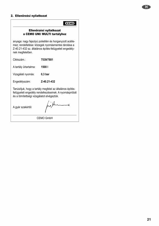
2. Ellenőrzési nyilatkozat
Ellenőrzési nyilatkozata CEMO UNI/ MULTI tartályhoz
anyaga: nagy fajsúlyú polietilén és horganyzott acélle-mez; rendeltetése: közegek nyomásmentes tárolása aZ-40.21-432 sz. általános építés-felügyeleti engedély-nek megfelelően.
Cikkszám.: 7539/7881
A tartály űrtartalma: 1500 l
Vizsgálati nyomás: 0,3 bar
Engedélyszám: Z-40.21-432
Tanúsítjuk, hogy a tartály megfelel az általános építés-felügyeleti engedély rendelkezéseinek. A nyomáspróbátés a tömítettségi vizsgálatot elvégeztük.
A gyár szakértői:
CEMO GmbH
H
21

N
CEMO UNI-/MULTI-tank 1500 l
Tankpapirer og tekniske informasjonerGodkjennelses - nr.: Z-40.21-432
Viktige dokumenter for den som eier/driver anlegget!Ta godt vare på dokumentene!(Dokumentene må vises frem ved kontroll av tankan-legget.)
1. Transport-, monterings- og driftsveiledning
Denne anvisningen gjelder for CEMO UNI-/MULTI-tank 1500 li henhold til den generelle byggekontroll-godkjennelsen Z-40.21-432.
CEMO UNI-/MULTI-tanker leveres som en enhet meden beskyttelse som er støtsikker og som holdes av enkrympehette. Samtidig befinner det seg en beskyttelse påtanksiden til påfyllingsindikatoren.Tankene er fra fabrikken utstyrt med innebygget lekkas-jesonde.
Dekselet må fjernes på oppstillingsstedet!
I en tankstuss finner dugodkjenningen i et hylstermedtransport-, monterings- og driftsveiledningen, overvåkings-erklæringen og garantibeviset.
Ved oppstillingen av CEMO UNI-tanker må fotstativet leg-ges på gulvet og tanken stilles oppå. Man må kontrollereden loddrette sentreringen. Beholderen kan så skyves isin endelige posisjonen og sentreres slik at typeskiltet påforsiden alltid kan sees.
For CEMO MULTI-tank er fotstativet fast montert alleredefra fabrikken.
Tankene må kun stilles opp i rom som helt lukket.Det er ikke nødvendig med et ekstra samlerom!
For fyringsanlegg (ildsteder, skorsteiner, forbindelsesstyk-ker) må man overholde en avstand på minst 1 meter.
Tankene må ikke stillesa) i gjennomganger og gjennomkjøringer,b) i trappeoppganger,c) i generelt tilgjengelige ganger,d) på taket til bolighus, sykehus, kontorbygg eller lin-kende hus og i deres loft,
e) på kontorer,f) i bar- og restaurantrom
.
Påfyllingsindikatoren må føres inn i en av de øverstestussene. Først fjernes låsehetten, deretter stikkes over-falsmutterene nedenfra over indikatoren og gjengehylseneskrus på. Deretter festes påfyllingsindikatoren på en slikmåte at overfalsmutteren skrus på stussen ved bruk avden vedlagte tetningen.
Tankene kan også knyttes med en fast tilkopling tilautomatisk uttak ved hjelp av nedsenkbare pumper ellerpumper med etterfølgende trykklagring. Anleggene måda utsyres med en sikkerhetsautomatikk, som utelukkerhevertvirkning.
Ved automatisk tømming må man sørge for tilstrekkeligventilasjon av tankene, f. eks. ved bruk av en ventilas-jonssopp (2“), som kan settes inn i den gjengehylsen somfinnes.
For lagring av medier som ikke er brennbare den dertilforeskrevne tilkoplingen av en fast påfyllingsslange, finnesdet en overfyllingssikring som tilbehør med bestillingsnr.7330. For lagring av brukte smøre-, hydraulikk- ellervarmebæreroljer, finnes det en lekkasjesonde som tilbehørmed bestillingsnr. 7391.
2. Overvåkingserklæring
Overvåkingserklæringfor CEMO UNI-tank / MULTI-tank
i polyetylen høy tetthet og forsinket stålplate for trykkløslagring av medier i henhold til den generelle byggekon-troll-godkjennelsen Z-40.21-432.
Artikkel-nr.: 7539/7881
Beholderinnhold: 1500 l
Kontrolltrykk: 0.3 bar
Godkjennelsesnummer: Z-40.21-432
Vi bekrefter at beholderen overholder kravene til dengenerelle byggekontroll-godkjennelsen.Trykk- og tetthetskontroll ble gjennomført.
Fabrikkens sakkyndige:
CEMO GmbH
22

NL
CEMO UNI-/MULTI-tank 1500 l
Tankpapieren en technische informatieGoedkeuringsnr.: Z-40.21-432
Belangrijke documentatie voor de ondernemer!Zorgvuldig bewaren!(Documentatie moet bij controles van de tankinstallatieworden getoond.)
1. Transport-, montage- en gebruikshandleiding
Deze handleiding geldt voor de CEMO UNI-/MULTI-tank 1500 lvolgens de algemene bouwtoezichtgoedkeuring Z-40.21-432.
De CEMO UNI-/MULTI-tanks worden als eenheid met eendoor een krimpkap vastgehouden, schokvrije afdekkingvan recyclebaar materiaals als transportbeveiliginggeleverd. Tegelijkertijd is in de afdekking aan de tankzijdede vulpeilaanduiding geplaatst.De tanks zijn in de fabriek met een ingebouwde leksondeuitgerust.
Het deksel mag pas op de opstelplaats worden verwijderd!
In een tankstomp bevinden zich in een hoes de goed-keuring met transport-, montage- en gebruikshandleiding,toezichtverklaring en garantieverklaring.
Bij de opstelling van de CEMO UNI-tank moet het voetstukop de vloer worden gelegd, waarna de tank erop wordt ge-zet. De verticale uitlijning moet worden gecontroleerd. Detank kan dan op zijn definitieve plaats worden geschovenen zo worden uitgelijnd dat het aan de voorkant aange-brachte typeplaatje altijd zichtbaar is.
Bij de CEMO MULTI-Tank is het voetstuk reeds in defabriek vast gemonteerd.
De tanks mogen uitsluitend in aan alle zijden gesloten ru-imtes worden opgesteld.Een aanvullende opvangruimte is niet noodzakelijk!
Voor stookinstallaties (stookplaatsen, schoorstenen, ver-bindingsstukken) geldt een afstand van ten minste 1 m.
De tanks mogen nieta) in doorgangen en doorritten;b) in trappenhuizen;c) in algemeen toegankelijke gangen;d) op daken van woningen, ziekenhuizen, kantoorgebou-wen en soortgelijke gebouwen en op de zolders ervan;
e) in kantoorruimtes;f) in gast- en kastruimtes;
worden opgesteld.
In een van de bovenste stompen moet de vulpeilaandui-ding worden aangebracht. De afsluitkap wordt eerst ver-wijderd. Vervolgens worden de wartelmoeren van onderenover de aanduiding gestoken en de schroefdraadbus eropgeschroefd. Daarna wordt de vulpeilaanduiding zo beve-stigd dat de wartelmoer met de meegeleverde pakking opde stomp worden geschroefd.
De tanks kunnen ook via een vaste aansluiting voor hetautomatisch aftappen middels dompelpompen resp. pom-pen met nageschakeld drukreservoir worden aangesloten.De installaties moeten dan worden voorzien van een auto-matische beveiliging die een hefboomwerking uitsluit.
Bij automatisch aftappen moet voor voldoende ventilatievan de tank worden gezorgd, bijv. door het gebruik vaneen be- en ontluchtingsringklep (2“), die in de aanwezigeschroefdraadbus kan worden aangebracht.
Voor de opslag van niet-brandbare stoffen en de daar-voor voorgeschreven aansluiting van een vaste vulleidingis als accessoire de overloopbeveiliging met bestelnr.7330 verkrijgbaar. Voor de opslag van gebruikte smeer-,hydraulische of warmtegeleidende olie is als accessoire deleksonde met bestelnr. 7391 verkrijgbaar.
2. Toezichtverklaring
Toezichtverklaringvoor CEMO UNI-tank / MULTI-tank
van polyethyleen met hoge dichtheid en verzinktestaalplaat voor de drukloze opslag van stoffen volgensde algemene bouwtoezichtgoedkeuring Z-40.21-432.
Artikelnr.: 7539/7881
Tankinhoud: 1500 l
Testdruk: 0,3 bar
Goedkeuringsnummer: Z-40.21-432
Wij verklaren dat de tank voldoet aan de bepalingenvan de algemene bouwtoezichtgoedkeuring. De druk-en lekkagecontrole werd uitgevoerd.
De experts:
CEMO GmbH
23

P
UNI-/MULTI-Tanque CEMO 1500 l
Documentação e informações técnicasdo tanque Licença nº: Z-40.21-432
Documentos importantes para o operador!Guardar em local seguro!(Os documentos deverão ser apresentados em caso deinspecção dos tanques.)
1. Instruções de transporte,montagem e operação
Estas instruções são destinadas ao UNI-/MULTI-TanqueCEMO 1500 l conforme a licença geral de supervisão deconstrução Z-40.21-432.
Cada UNI-/MULTI-Tanque CEMO é fornecido com umatampa resistente a impacto, confeccionada em materialreciclável e fixada com uma película para a protecçãodurante o transporte. O medidor de nível encontra-sealojado do lado do tanque na tampa.Os tanques são dotados de sensor de vazamento incor-porado.
A tampa só deverá ser retirada no local de instalação dotanque!
Em um conector do tanque encontra-se um envelopecontendo a licença, as instruções de transporte, monta-gem e operação, a declaração de inspecção e o termo degarantia.
Na instalação do UNI-Tanque CEMO, deve-se colocaros pés do tanque sobre o chão e posicioná-lo sobre osmesmos. Certificar-se de que o tanque seja posicionadoexatamente na vertical. O tanque pode, então, ser mo-vimentado para a sua posição definitiva de modo que aplaca sobre a qual está gravado o modelo fique visível.
Os pés do MULTI-Tanque CEMO já vêm montados defábrica.
Só é permitido instalar os tanques em espaços fechadosem todos os lados.Não é necessário equipamento adicional para acolecta!
Deve-se manter uma distância de no mínimo 1 m deequipamentos de combustão (fornalhas, chaminés ecanalizações).
Os tanques não devem ser instaladosa) em passagens de pedestres ou veículos,b) em escadas,c) em corredores de livre acesso,d) sobre telhados ou em sótãos de residências,hospitais, escritórios ou semelhantes,
e) em escritórios,f) em bares ou restaurantes
.
O indicador de nível deve ser fixado em um dos conec-tores localizados na parte superior. Retira-se a tampade fecho, coloca-se a porca de capa por baixo e sobre oindicador e rosqueia-se as buchas roscadas. Em seguida,o indicador de nível é fixado de tal modo que a porca decapa seja rosqueada sobre os conectores utilizando avedação fornecida.
Os tanques também podem ser instalados com umaconexão fixa para a retirada automática utilizando bombassubmersíveis ou bombas dotadas de acumulador de pres-são. Em seguida, deve-se instalar nos equipamentos ummecanismo automático de segurança para evitar o efeitosifão.
Na retirada automática, deve-se certificar que no tanquehaja circulação suficiente de ar utilizando, por exemplo,uma abertura para ventilação e circulação de ar (2), quepode ser instalada na bucha roscada existente.
Está disponível como acessório um dispositivo de anti-transbordamento (nº 7330) a ser utilizado caso se preten-da armazenar substâncias não inflamáveis com a conexãocom uma linha de alimentação fixa respectivamenteprescrita. Para o armazenamento de óleos lubrificantes,hidráulicos e térmicos usados está disponível como aces-sório o sensor de vazamento (nº 7391).
24
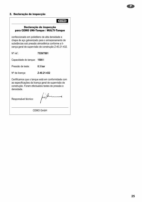
2. Declaração de inspecção
Declaração de inspecçãopara CEMO UNI-Tanque / MULTI-Tanque
confeccionado em polietileno de alta densidade echapa de aço galvanizado para o armazenamento desubstâncias sob pressão atmosférica conforme a li-cença geral de supervisão de construção Z-40.21-432.
Nº ref.: 7539/7881
Capacidade do tanque: 1500 l
Pressão de teste: 0.3 bar
Nº da licença: Z-40.21-432
Certificamos que o tanque está em conformidade comas especificações da licença geral de supervisão deconstrução. Foram efectuados testes de pressão edensidade.
Responsável técnico:
CEMO GmbH
P
25

PL
Zbiornik CEMO UNI/MULTI 1500 l
Dokumentacja zbiornika i informacjetechniczneNr świadectwa dopuszczenia: Z-40.21-432
Ważna dokumentacja dla użytkownika!Należy zapewnić staranne przechowanie!(Dokumentację należy okazać podczas kontrolizbiornika.)
1. Instrukcja dotycząca transportu, montażu iużytkowania
Niniejsza instrukcja dotyczy zbiornika CEMO UNI/MULTI 1500 lzgodnie z niemiecką aprobatą dopuszczającą do stosowania w bu-downictwie (Allgemeine Bauaufsichtliche Zulassung) Z-40.21-432.
Zbiorniki CEMO UNI/MULTI są dostarczane jako zespół zprzytrzymywaną powłoką kurczliwą i odporną na uderzeniapokrywą wykonaną z materiału przeznaczonego doodzysku jakopochrona transportowa. Jednocześnie wpokrywie po stronie zbiornika jest przymocowany wskaźnikpoziomu napełnienia.Zbiorniki są wyposażone fabrycznie w sondę wykrywającąprzeciek.
Wieko zdejmuje się dopiero w miejscu ustawienia!
W króćcu zbiornikaznajduje się zabezpieczone w futeraleświadectwo dopuszczenia wraz z instrukcją dotyczącątransportu, montażuużytkowania, deklaracja nadzoru iformularz gwarancyjny.
Przy ustawianiu zbiornika CEMO UNI należy postawićna podłodze ramę, a następnie sadzić w niej zbiornik.Sprawdzić, czy zbiornik stoi równo w pionie. Zbiornikmożna wtedy dosunąć w ostateczne położenie i ustawić wtaki sposób, by przymocowana z przodu tabliczka znamio-nowa była na stałe widoczna.
W zbiorniku CEMO MULTI rama jest zamontowanafabrycznie na stałe.
Zbiorniki wolno stawiać wyłącznie w całkowiciezamkniętych pomieszczeniach.Nie trzeba zapewniać dodatkowego obszaru dowyłapywania!
Od instalacji opałowych (paleniska, kominy, złączki) musibyć zachowany odstęp co najmniej 1 m.
Zbiorników nie wolno stawiaća) w przejściach i przejazdach,b) w pomieszczeniach ze schodami,c) w ogólnodostępnych korytarzach,d) na dachach domów mieszkalnych, szpitalach ibiurowcach lub podobnych budynkach, jak równieżna poddaszach i strychach,
e) w pomieszczeniach biurowych,f) w pomieszczeniach gościnnych
itp.
Do jednego z górnych króćców wprowadza się wskaźnikpoziomu napełnienia zbiornika. W tym celu należy najpierwzdjąć pokrywę zamykającą, założyć od dołu nakrętki nasa-dowe na wskaźnik i przykręcić na gniazda gwintowane.Następnie wskaźnik poziomu napełnienia mocuje się wtaki sposób, by nakrętkę nasadową można było nakręcićna króciec przy użyciu dostarczonej uszczelki
Zbiorniki mogą być również przyłączone stałymprzyłączem do automatycznego pobierania za pomocąpomp zanurzeniowych wzgl. pomp z zamontowanym zanimi zasobnikiem ciśnieniowym. Instalacje należy wów-czas wyposażyć w automatykę zabezpieczającą, którabędzie chroniła instalację przed przybieraniem poziomu.
Przy automatycznym pobieraniu należy zadbać odostateczną wentylację zbiorników, np. poprzez zastoso-wania zaworu napowietrzania i odpowietrzania (2“), którymożna zamontować w dostępnym gnieździe gwintowanym.
W celu składowania niepalnych mediów, a także doprzeznaczonego do nich przyłącza stałego przewodunapełniającego, w wyposażeniu opcjonalnym pod nume-rem kat. 7330 dostępne jest zabezpieczenie przelewowe.W celu składowania zużytych olejów smarnych, hydraulicz-nych i termoprzewodzących w wyposażeniu opcjonalnympod numerem kat. 7391 dostępna jest sonda wykrywającaprzecieki.
26

2. Deklaracja nadzoru
Deklaracja nadzoruzbiornika CEMO UNI / MULTI
z polietylenu o wysokiej gęstości i ocynkowanej bla-chy stalowej bezciśnieniowego składowania mediówzgodnie z niemiecką aprobatą dopuszczającą do sto-sowania w budownictwie (Allgemeine BauaufsichtlicheZulassung) Z-40.21-432.
Nr artykułu: 7539/7881
Pojemność zbiornika: 1500 l
Ciśn. kontrolne: 0.3 bar
Nr świadectwa dopuszczenia: Z-40.21-432
Oświadczamy, że zbiornik odpowiada ustaleniomniemieckiej aprobaty dopuszczającej do stosowaniaw budownictwie (Allgemeine Bauaufsichtliche Zulas-sung). Przeprowadzono badanie ciśnieniowe i badanieszczelności.
Rzeczoznawcy:
CEMO GmbH
PL
27
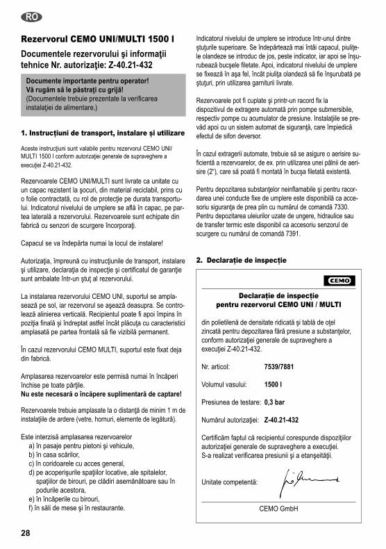
28
Rezervorul CEMO UNI/MULTI 1500 lDocumentele rezervorului şi informaţiitehnice Nr. autorizaţie: Z-40.21-432
Documente importante pentru operator!Vă rugăm să le păstraţi cu grijă!(Documentele trebuie prezentate la verificareainstalaţiei de alimentare.)
1. Instrucţiuni de transport, instalare şi utilizare
Aceste instrucţiuni sunt valabile pentru rezervorul CEMO UNI/MULTI 1500 l conform autorizaţiei generale de supraveghere aexecuţiei Z-40.21-432.
Rezervoarele CEMO UNI/MULTI sunt livrate ca unitate cuun capac rezistent la şocuri, din material reciclabil, prins cuo folie contractată, cu rol de protecţie pe durata transportu-lui. Indicatorul nivelului de umplere se află în capac, pe par-tea laterală a rezervorului. Rezervoarele sunt echipate dinfabrică cu senzori de scurgere încorporaţi.
Capacul se va îndepărta numai la locul de instalare!
Autorizaţia, împreună cu instrucţiunile de transport, instalareşi utilizare, declaraţia de inspecţie şi certificatul de garanţiesunt ambalate într-un ştuţ al rezervorului.
La instalarea rezervorului CEMO UNI, suportul se ampla-sează pe sol, iar rezervorul se aşează deasupra. Se contro-lează alinierea verticală. Recipientul poate fi apoi împins înpoziţia finală şi îndreptat astfel încât plăcuţa cu caracteristiciamplasată pe partea frontală să fie vizibilă permanent.
În cazul rezervorului CEMO MULTI, suportul este fixat dejadin fabrică.
Amplasarea rezervoarelor este permisă numai în încăperiînchise pe toate părţile.Nu este necesară o încăpere suplimentară de captare!
Rezervoarele trebuie amplasate la o distanţă de minim 1 m deinstalaţiile de ardere (vetre, hornuri, elemente de legătură).
Este interzisă amplasarea rezervoarelora) în pasaje pentru pietoni şi vehicule,b) în casa scărilor,c) în coridoarele cu acces general,d) pe acoperişurile spaţiilor locative, ale spitalelor,spaţiilor de birouri, pe clădiri asemănătoare sau înpodurile acestora,
e) în încăperile cu birouri,f) în săli de mese şi în restaurante.
Indicatorul nivelului de umplere se introduce într-unul dintreştuţurile superioare. Se îndepărtează mai întâi capacul, piuliţe-le olandeze se introduc de jos, peste indicator, iar apoi se înşu-rubează bucşele filetate. Apoi, indicatorul nivelului de umplerese fixează în aşa fel, încât piuliţa olandeză să fie înşurubată peştuţuri, prin utilizarea garniturii livrate.
Rezervoarele pot fi cuplate şi printr-un racord fix ladispozitivul de extragere automată prin pompe submersibile,respectiv pompe cu acumulator de presiune. Instalaţiile se pre-văd apoi cu un sistem automat de siguranţă, care împiedicăefectul de sifon deversor.
În cazul extragerii automate, trebuie să se asigure o aerisire su-ficientă a rezervoarelor, de ex. prin utilizarea unei pâlnii de aeri-sire (2“), care să poată fi montată în bucşa filetată existentă.
Pentru depozitarea substanţelor neinflamabile şi pentru racor-darea unei conducte fixe de umplere este disponibilă ca acce-soriu siguranţa de prea plin cu numărul de comandă 7330.Pentru depozitarea uleiurilor uzate de ungere, hidraulice saude transfer termic este disponibil ca accesoriu senzorul descurgere cu numărul de comandă 7391.
2. Declaraţie de inspecţie
Declaraţie de inspecţiepentru rezervorul CEMO UNI / MULTI
din polietilenă de densitate ridicată şi tablă de oţelzincată pentru depozitarea fără presiune a substanţelor,conform autorizaţiei generale de supraveghere aexecuţiei Z-40.21-432.
Nr. articol: 7539/7881
Volumul vasului: 1500 l
Presiunea de testare: 0,3 bar
Numărul autorizaţiei: Z-40.21-432
Certificăm faptul că recipientul corespunde dispoziţiilorautorizaţiei generale de supraveghere a execuţiei.S-a realizat verificarea presiunii şi a etanşeităţii.
Unitate competentă:
CEMO GmbH
RO

RUS
29
Бак CEMO UNI/MULTI 1500 л
Документация на бак и техническаяинформация номер допуска: Z-40.21-432Важная документация для эксплуатирующейорганизации! Хранить аккуратно!(Документация должна быть предъявлена прииспытаниях бака).
2. Инструкция по транспортировке,сборке и эксплуатации
Данная инструкция предназначена для бака CEMO UNI/MULTI1500 л согласно общему допуску органа строительногонадзора Z-40.21-432.
Баки CEMO UNI/MULTI поставляются в виде единогокомпонента с ударопрочной крышкой, удерживаемойусадочным чехлом из пригодного для вторичнойпереработки материала в качестве защиты притранспортировке. Кроме того, в крышке со стороныбака установлен указатель уровня. Баки оснащеныустанавливаемым на заводе датчиком утечек.
Крышку разрешается снимать только на месте установки!
В одном из патрубков бака в пакете находится доку-ментация, куда входят допуск к эксплуатации, инструк-ция по транспортировке, установке и эксплуатации,заявление о соответствии требованиям надзорныхорганов и гарантийное свидетельство.
При установке бака CEMO UNI опорная рама ставитсяна пол, после чего на нее устанавливается сам бак.Необходимо проверить вертикальность установленногобака. После этого емкость можно переместить в ееокончательное положение и выровнять таким образом,чтобы была постоянно видна размещенная на торце-вой стороне заводская табличка.
В случае бака CEMO MULTI опорная рама полностьюсмонтирована уже на заводе.
Баки разрешается устанавливать только в помеще-ниях, закрытых со всех сторон.Дополнительное помещение для сбора жидкостейне требуется!Необходимо соблюдать расстояние не менее одногометра от топочных установок (очагов, дымовых труб,соединений).
Не разрешается устанавливать бакиa) в проходах и проездах,b) в лестничных помещениях,c) в общедоступных коридорах,d) на крышах жилых домов, больниц,офисных центров и подобных зданий, а такжев чердачных помещениях,
e) в офисных помещениях,f) помещениях для приема гостей и распитияспиртных напитков.
В один из верхних патрубков следует установить ука-затель уровня. Для этого необходимо снять заглушку,установить на указатель снизу накидные гайки и накру-тить их на резьбовые втулки. После этого указательуровня крепится посредством закручивания накиднойгайки на патрубок с входящим в комплект поставкиуплотнением.
Кроме того, баки можно подсоединить к стационарноймагистрали для автоматического отбора жидкости спомощью погружных насосов или насосов с последую-щим ресивером. При этом такие установки оснащаютсязащитной автоматикой, предупреждающей возникнове-ние сифонного эффекта.
В случае автоматического отбора жидкости требуетсяобеспечить достаточный уровень вентиляции баков,например, с помощью грибкового вентиляционногоклапана (2“), который устанавливается в имеющеесярезьбовое гнездо.
Для хранения негорючих жидкостей и обеспеченияпредусматриваемого в данном случае прочного под-соединения к наполняющему трубопроводу возможнаустановка поставляемого в качестве принадлежностиустройства защиты от переполнения (номер для зака-за: 7330). В случае хранения отработанного смазочныхмасел, гидравлических или теплонесущих масел, вкачестве принадлежности предлагается датчик утечек(номер для заказа: 7391).
2. Заявление о соответствии требованиямнадзорных органов
Заявление о соответствии требованиямнадзорных органов для бака CEMO UNI/MULTIиз полиэтилена высокой плотности и оцинкован-ного стального листа для безнапорного храненияжидкостей согласно общему допуску органастроительного надзора Z-40.21-432.
Артик. №: 7539/7881Емкость бака: 1500 лИспытательное давление: 0,3 барНомер допуска: Z-40.21-432Настоящим удостоверяется, что данный резер-вуар соответствует положениям общего допускаоргана строительного надзора. Испытание давле-нием и проверка герметичности выполнены.
Заводские эксперты:
CEMO GmbH
S
CEMO UNI-/MULTI-tank 1500 l
Tankpapper och teknisk informationRegistreringsnummer: Z-40.21-432
Viktiga underlag för idkaren!Förvara dem noga!(Underlagen ska kunna visas upp när tankanläggningenkontrolleras.)
1. Transport-, monterings- och bruksanvisning
Den här bruksanvisningen gäller för CEMO UNI-/MULTI-tank 1500 lenligt typgodkännandet av byggprodukter Z-40.21-432.
CEMO UNI-/MULTI-tankar levereras som en enhet med ettav en krympplast fasthållet stöttåligt skydd av återvinnings-bart material som transportskydd. På tanksidan i självaskyddet finns nivåindikatorn.Tankarna utrustas med en läckagesond i fabriken.
Ta inte bort locket förrän på uppställningsplatsen!
I en plastficka i enav tankstosarna finnsregistreringen medtransport-, monterings- och bruksanvisning, övervaknings-försäkran och garantibevis.
Lägg fotstativet på golvet och sätt tanken ovanpå det, närdu ska ställa upp CEMO UNI-tankarna. Kontrollera att destår lodrätt. Det går att skjuta tanken till sin slutgiltiga posi-tion och justera in den på ett sådant sätt, att typskylten påkortsidan syns hela tiden.
På CEMO MULTI-tanken har fotstativet redan monteratsfast i fabriken.
Tankarna får bara placeras i slutna utrymmen.Det krävs inget extra uppsamlingsutrymme!
Från eldningsanläggningar (eldstäder, skorstenar, förbin-delsestycken) måste det vara ett avstånd på minst 1 meter.
Tankarna får intea) placeras i passager eller genomfarter,b) i trappuppgångar,c) i allmänt tillgängliga hallar,d) på taket eller på vinden på bostadshus, sjukhus, kon-torsbyggnader och liknande byggnader,
e) på kontor ellerf) på krogar eller utskänkningsställen
.
För in nivåindikatorn i en av de övre stosarna. Ta då förstbort locket, sätt överfallsmuttern underifrån över indikatornoch skruva på gänghylsorna. Fäst sedan nivåindikatorn påett sådant sätt att överfallsmuttern skruvas fast på stosentillsammans med den medsända tätningen.
Tankarna kan även fastanslutas för automatisk mottagningmed hjälp av dränkbara pumpar eller pumpar med efterföl-jande tryckackumulator. Förse sedan anläggningarna meden säkerhetsautomatik som utesluter en hävertverkan.
Se vid automatisk tappning till att en tillräcklig påluftningav tanken sker, till exempel genom att en på- och avluft-ningsenhet (2“), som kan placeras i den befintliga gänghyl-san, används.
För förvaring av icke brännbara medier och den förändamålet avsedda anslutningen av en fast påfyllningsled-ning finns det en överfyllnadssäkring, beställningsnummer7330, som tillbehör. För förvaring av använda smörj-,hydraulik- eller värmebäraroljor finns det en läckagesond,beställningsnummer 7391, som tillbehör.
2. Övervakningsförsäkran
Övervakningsförsäkrangällande CEMO UNI-tank/MULTI-tank
av polyeten med hög täthet och förzinkad stålplåt förtrycklös förvaring av medier enligt typgodkännandet avbyggprodukter Z-40.21-432.
Artikelnummer: 7539/7881
Tankvolym: 1 500 l
Kontrolltryck: 0,3 bar
Registreringsnummer: Z-40.21-432
Vi intygar att tanken uppfyller kraven i typgodkännandetav byggprodukter. Tryck- och täthetskontroll har utförts.
De sakkunniga i fabriken:
CEMO GmbH
30

31
SF
CEMO UNI-/MULTI -tankki 1500 l
Tankkiin liittyvät asiakirjat ja tekniset tiedotHyväksyntänro: Z-40.21-432
Tärkeitä käyttäjän asiakirjoja!Säilytä huolellisesti!(Asiakirjat on esitettävä tankkilaitteistontarkastuksessa.)
1. Kuljetus-, asennus- ja käyttöohje
Tämä ohje koskee CEMO UNI-/MULTI -tankkia 1500 lSaksan yleisen rakennehyväksynnän Z-40.21-432 mukaisesti.
Die CEMO UNI-/MULTI -tankit toimitetaan yhtenäisenäyksikönä, jossa on kuljetussuojana kutistehupun avullakiinnitetty iskunkestävä ja kierrätettävää materiaaliaolevasuojus. Suojukseen on kiinnitetty nestepinnan osoitinsäiliön puolelle.Tankit on varustettu tehtaalla sisäänrakennetulla vuotoan-turilla.
Kannen saa irrottaa vasta asennuspaikassa!
Tyyppihyväksyntä,kuljetus-, asennus- ja käyttöohjeet,tarkastusilmoitus,ja takuutodistusovatkuoren sisällä yhdessätankkiyhteessä.
CEMO UNI -tankkia pystytettäessä on jalkateline ase-tettava maahan ja tankki laitettava sen päälle. Tarkasta,että tankki tulee pystysuoraan. Säiliö voidaan sitten työn-tää lopulliseen asentoonsa ja oikaista niin, että etupuolellaoleva tyyppikilpi on aina näkyvissä.
CEMO MULTI -tankissa jalkateline on asennettu jotehtaalla.
Tankin saa asentaa ainoastaan joka puolelta suljettuuntilaan.Erillistä keruutilaa ei tarvita!
Lämmityslaitteisiin (tulisijat, savupiiput, yhdyskappaleet)on pidettävä vähintään 1 metrin välimatka.
Tankkia ei saa asentaa:a) läpikulku- tai läpiajopaikkoihin,b) rappukäytäviin,c) käytäviin, joihin on yleinen pääsy,d) asuintalojen, sairaaloiden, toimistojen tai muiden va-staavien rakennusten katoille tai niiden ullakkotiloihin,
e) toimistotiloihin,f) ravintoloihin tai baaritiloihin
Nestepinnan osoitin on työnnettävä yhteen ylemmistäyhteistä. Sulkukapseli on poistettava tätä ennen, hattumu-tterit asetettava alhaalta osoittimen päälle ja kierreholkitruuvattava paikoilleen. Tämän jälkeen nestepinnan osoitinkiinnitetään sillä tavoin, että hattumutteri ruuvataan tankki-yhteeseen toimitukseen sisältyvän tiivisteen kanssa.
Tankit voidaan liittää myös kiinteällä liitännällä, jolloinpolttonestettä voidaan syöttää automaattisesti uppopump-pujen tai paineakulla varustettujen pumppujen avulla.Tällöinkin ne on varustettava lappovaikutuksen estävälläturva-automatiikalla.
Automaattisen oton yhteydessä on huolehdittava tankinriittävästä ilmanvaihdosta, esim. ilmanvaihtoputken (2“)avulla, joka voidaan liittää valmiiseen kierreholkkiin.
Palamattomien aineiden säilytystä ja sitä varten määrättyäkiinteän täyttöliitännän asennusta varten on saatavanalisävarusteena ylitäyttösuoja, jonka tilausnumero on 7330.Käytettyjen voitelu-, hydrauliikka- tai lämmönsiirtoöljyjensäilytystä varten on saatavana lisävarusteena vuotoanturi,jonka tilausnumero on 7391.
2. Tarkastusilmoitus
TarkastusilmoitusCEMO UNI -tankille / MULTI -tankille
valmistettu erittäin tiiviistä polyetyleenistä ja sinkitystäteräslevystä, tarkoitettu käytettäväksi väliaineiden pai-neettomaan varastointiin Saksan yleisen rakennehyväk-synnän Z-40.21-432 mukaisesti.
Tuotenro: 7539/7881
Säiliön tilavuus: 1500 l
Koestuspaine: 0,3 baria
Hyväksyntänumero: Z-40.21-432
Vahvistamme täten, että säiliö vastaa Saksan yleisenrakennehyväksynnän määräyksiä. Paine- ja tiiviystar-kastus suoritettiin.
Valmistajan asiantuntijat:
CEMO GmbH
Nádrž CEMO UNI/MULTI 1 500 l
Podklady a technické informácie o nádržiČíslo povolenia: Z-40.21-432
Dôležité podklady pre prevádzkovateľa!Starostlivo uschovajte!(Podklady predložte pri skúškach skladovaciehozariadenia s nádržami.)
1. Návod na prepravu, montáž a prevádzku
Tento návod platí pre nádrž CEMO UNI/MULTI 1500 lpodľa všeobecného povolenia stavebného dozoru Z-40.21-432.
Nádrže CEMO UNI/MULTI sa expedujú ako samostatnéjednotky a na ochranu pri preprave sú zabalené v krytez opätovne použiteľného, proti nárazom odolného materiálua v zmršťovacom obale. V kryte je na boku nádrže jezároveň umiestnený ukazovateľ výšky hladiny. Nádrže súz výroby vybavené zabudovanou sondou netesnosti.
Kryt odstráňte až na mieste montáže!
V hrdle nádrže sa v puzdre nachádza povolenie s návodomna prepravu, montáž a prevádzku, prehlásenie o kontrolea záručný list.
Pri inštalovaní nádrže CEMO UNI položte podstavec napodlahu a naň uložte nádrž. Skontrolujte zvislé vyrovnanie.Nádrž je možné potom posunúť do konečnej polohya vyrovnať tak, aby bol vždy viditeľný typový štítok, ktorý jeumiestnený na čelnej strane.
Na nádrži CEMO MULTI je podstavec pevne namontovanýuž z výroby.
Nádrže je povolené inštalovať len v úplne uzavretýchpriestoroch.Nie je nutná montáž prídavnej záchytnej nádrže!
Od spaľovacích zariadení (kúreniská, komíny, spojovaciediely) sa musí vždy dodržať vzdialenosť najmenej 1 m.
Je zakázané inštalovať nádržea) v priechodoch a prejazdoch,b) na schodištiach,c) na všeobecne prístupných chodbách,d) na strechách obytných domov, nemocníc, kancelárskychbudov a podobných budov a v ich podkroví,
e) v kancelárskych miestnostiach,f) v pohostinstvách a výčapoch.
Do jedného z horných hrdiel sa musí zaviesť ukazovateľ výškyhladiny. Najprv odoberte uzáver, prevlečné matice nasuňtezdola cez ukazovateľ a naskrutkujte puzdrá so závitom. Potomsa ukazovateľ výšky hladiny upevní naskrutkovaním prevlečnejmatice na hrdlo. Pri upevnení použite priložené tesnenie.
Nádrže je možné pripojiť i pevnou prípojkou na automatickýodber pomocou ponorných čerpadiel, resp. čerpadiel s nás-ledne pripojenou tlakovou nádobou. Zariadenia potom musiabyť vybavené bezpečnostnou automatikou, ktorá vylučujemožnosť pôsobenia násosky.
Pri automatickom odbere sa musí zabezpečiť dostatočnézavzdušnenie nádrží, napr. použitím zavzdušňovaciehoa odvzdušňovacieho hríba (2“), ktorý je možné vsadiť dopuzdra so závitom.
Na skladovanie nehorľavých médií a predpísané pripojeniepevného plniaceho potrubia existuje ako príslušenstvo poistkaproti preplneniu s objednacím číslom 7330. Na skladovaniepoužitých mazacích, hydraulických olejov alebo olejov naprenos tepla existuje ako príslušenstvo sonda na zisťovanienetesností s objednacím číslom 7391.
2. Prehlásenie o kontrole
Prehlásenie o kontrolenádrže CEMO UNI / MULTI
z polyetylénu vysokej hustoty a pozinkovanéhooceľového plechu na beztlakové skladovanie médií podľavšeobecného povolenia stavebného dozoru Z-40.21-432.
Číslo výrobku: 7539/7881
Objem nádrže: 1500 l
Skúšobný tlak: 0.3 bar
Číslo povolenia: Z-40.21-432
Potvrdzujeme, že nádrž zodpovedá ustanoveniamvšeobecného povolenia stavebného dozoru. Bolavykonaná tlaková skúška a skúška tesnosti.
Podnikoví znalci:
CEMO GmbH
SK
32
SLO
CEMO UNI/MULTI tank 1500 l
Dokumenti za tank in tehnične informacijeŠt. dovoljenja: Z-40.21-432
Pomembni dokumenti za upravljalca!Skrbno shranite!(dokumente je treba pokazati pri preverjanju tanka.)
1. Navodila za transport, montažo in uporabo
Ta navodila veljajo za CEMO UNI/MULTI tank 1500 lv skladu s splošnim dovoljenjem gradbenega nadzora Z-40.21-432.
CEMO UNI/MULTI tanki se dobavijo kot enota sprekritjem odpornim na udarce, ki ga drži skrčljiv pokrov,pizreciklažnega materiala kot zaščita pri transportu. Istočasnoje v prekritju na strani tanka nameščen prikaz nivojapolnosti.Tanki so tovarniško opremljeni z vgrajeno sondo puščanja.
Pokrov odstranite šele na kraju postavitve!
V nastavku tanka se v ovoju nahaja dovoljenje z navodiliza transport, montažo in uporabo, izjava o nadzoru in ga-rancijska listina.
Pri postavitvi tanka CEMO UNI je treba podnožje položitina tla in tank postaviti nanj. Navpično usmeritev je trebakontrolirati. Potem lahko posodo potisnete v dokončnipoložaj in jo naravnate tako, da je čelno nameščena tipskatablica na njej vidna.
Pri tanku CEMO MULTI je podnožje je že tovarniško mon-tirano.
Tanke smete postaviti samo v v celoti zaprtih prostorih.Dodaten prestrezni prostor ni potreben!
Do gorilnih naprav (gorišč, dimnikov, povezovalnih elemen-tov) je treba ohraniti razmik najmanj 1 m.
Tankov ne postavljajtea) v prehodih in podvozih,b) v stopniščih,c) v splošno dostopnih hodnikih,d)na strehah stanovanjskih zgradb, bolnišnic, pisarniškihposlopij in podobnih zgradb ter v njihovih podstrešnihprostorih,
e) v pisarnah,f) prostorih za goste in točenje pijače
V enega od zgornjih nastavkov je treba vstaviti prikaznivoja polnosti. Zaporni pokrov poprej odstranite, natičnematice od spodaj nataknite čez prikaz in privijte navojnepuše. Po tem prikaz nivoja polnosti pritrdite tako, danatično matico privijete na nastavke z uporabo priloženegatesnila.
Tanke lahko priključite s fiksnim priključkom zaavtomatski odvzem s potopnimi črpalkami oz. črpalkamis prigrajenim tlačnim zbiralnikom. Naprave potem morateopremiti z varovalno avtomatiko, ki izključuje učinek sifona.
Pri avtomatskem odvzemu je treba poskrbeti za zadostnoprezračevanje tankov, npr. z uporabo prezračevalnega inodzračevalnega nastavka („goba“: 2“), ki ga lahko vstavitev obstoječo navojno pušo.
Za skladiščenje negorljivih medijev in za zato predvidenpriključek za fiksno polnilno napeljavo kot pribor obstajavarovalo pred prenapolnitvijo z naroč. štev. 7330. Zaskladiščenje rabljenega mazalnega, hidravličnega olja aliolja toplotnih nosilcev kot pribor obstaja sonda za puščanjez naroč št. 7391.
2. Izjava o nadzoru
Izjava o nadzoruza CEMO UNI/MULTI tank
iz polietilena visoke gostote (HD-PE) in pocinkanejeklene pločevine za breztlačno skladiščenje medijevv skladu s splošnim dovoljenjem gradbenega nadzoraZ-40.21-432.
Št. artikla: 7539/7881
Prostornina posode: 1500 l
Preskusni tlak: 0.3 bar
Številka dovoljenja: Z-40.21-432
Potrjujemo, da posoda odgovarja določilom splošnegadovoljenja gradbenega nadzora. Gradbeni preizkus inpreverjanje tesnosti sta bila izvedena.
Strokovno podjetje:
CEMO GmbH
33

TR
CEMO UNI/MULTI Tank 1500 l
Tank evrakları ve teknik bilgilerRuhsat No.: Z-40.21-432
İşletmeci için önemli belgeler!Lütfen özenli bir şekilde saklayın!(Tank sisteminin kontrolleri sırasında belgelergösterilmelidir.)
1. Taşıma, montaj ve işletme talimatı
Bu talimat, CEMO UNI-/MULTI tank 1500 l için geçerlidirZ-40.21-432 sayılı genel inşaat kontrol ruhsatına göre.
CEMO UNI-/MULTI tankları, büzülmeli kapak ile tutulan vetekrar kullanılabilir malzemeden üretilmiş darbelere karşıdayanıklı taşıma koruması olarak kullanılan bir kapak ilebirlikte teslim edilir. Aynı zamanda kapağın tank tarafına birdoluluk seviyesi göstergesi yerleştirilmiştir.Tanklar, fabrikada entegre edilmiş kaçak sondası iledonatılmıştır.
Kapak, ancak kurulum yerinde çıkartılmalıdır!
Bir tank ağzındaki bir kılıfta, taşıma, montaj ve işletmetalimatı, denetim beyanı ve garanti belgesi ile birlikte ruh-sat bulunmaktadır.
CEMO UNI tankın kurulumu sırasında ayak şasisi yerekonulmalı ve tank da üzerine yerleştirilmelidir. Dikey pozi-syon kontrol edilmelidir. Ardından depo, nihai pozisyonunakaydırılabilir ve tip plakası sürekli görülebilir olacak şekildeyerleştirilebilir.
CEMO MULTI tankta, ayak şasisi fabrikada sabit olarakmonte edilmiştir.
Tanklar sadece her tarafı kapatılmış mekanlarda kurulabilir.Ek bir toplama odası gerekli değildir!
Yakma sistemlerinden (ocaklar, bacalar, bağlantğ parçaları)en az 1 m mesafe bırakılmalıdır.
Tanklar;a) Geçişler ve geçitler,b) Merdivenli odalar,c) Genel erişim bulunan koridorlar,d) Konutlar, hastaneler, ofis binaları ve benzeri binalarınçatıları ve bu yapıların çatı bölümleri,
e) Ofis odaları,f) Konuk ve dolap odalarına
kurulmamalıdır.
Üstteki ağızlarından birine doluluk seviyesi göstergesisokulmalıdır. Sızdırmazlık kepi daha önceden çıkartılır,üst somunlar alttan gösterge üzerine takılır ve dişli bur-çlar vidalanır. Daha sonra, birlikte teslim edilen contakullanılarak üst somunlar ağza vidalanacak şekilde dolulukseviyesi göstergesi sabitlenir.
Tanklar, dalgıç pompalar ya da müteakip basınç depolupompalar yardımıyla otomatik alma işlemi için sabit birbağlantıya da bağlanabilir. Sistemler, kaldırma etkisiniönleyen bir emniyet otomatiği ile donatılmalıdır.
Otomatik alma işlemi sırasında; Örn; mevcut dişli burcayerleştirilebilen bir havalandırma ve hava boşaltma mantarı(2“) kullanılarak tankların yeterli şekilde havalandırılmasısağlanmalıdır
Yanıcı olmayan maddelerin depolanması ve bu iş içinöngörülen sabit bir dolum hattının bağlanması için, akse-suar olarak 7330 sipariş numaralı aşırı dolum emniyetibulunmaktadır. Kullanılmış yağlama, hidrolik ya da ısıiletme yağları için, aksesuar olarak 7391 sipariş numaralıkaçak sondası bulunmaktadır.
2. Denetim beyanı
CEMO UNI Tank / MULTI tank içindenetim beyanı
Z.40.21-432 sayılı genel inşaat kontrol ruhsatına uygunolarak maddelerin basınçsız şekilde depolanması içinyüksek yoğunluklu polietilen ve galvanizli çelik sacdanüretilmiştir.
Ürün kodu: 7539/7881
Depo hacmi: 1500 l
Test basıncı: 0,3 bar
Ruhsat numarası: Z-40.21-432
Deponun, genel inşaat kontrol ruhsatındaki düzen-lemelere uygun olduğunu teyit ediyoruz. Basınç vesızdırmazlık kontrolü yapılmıştır.
Tesis bilirkişileri:
CEMO GmbH
34

IFGBD
35
Produktinformation
Die im Folgenden aufgeführten Tank-Typen
MT (MULTI-Tank) / UT (UNI-Tank)aus blasgeformten Polyethylen in Stahlauffangwanne, für die Lage-rung von Haushalts-Heizölen und Dieselkraftstoffen in Innenräumen,stimmen mit den Anforderungen der Norm EN 13341 überein.
Übersicht der wesentlichen Eigenschaften unserer Tanks, entsprechend der Norm EN 13341
TYP MT/UT 400 MT/UT 750 MT/UT 1000 MT/UT 1500Fassungsvolumen 430 l 770 l 1040 l 1630 lNutzvolumen 400 l 730 l 980 l 1540 lMechanische Festigkeit und Standfestigkeit:Masse des Innenbehälters (kg) 15,9 20,65 26,3 48,4Wanddicke (mm) 3,0 3,0 3,2 3,5Schmelzindex BestandenDichte BestandenZugfestigkeit BestandenBrandverhalten FDurchlässigkeit:Druckfestigkeit BestandenSchlagfestigkeit BestandenMedienbeständigkeit BestandenDichtheit BestandenBewitterungstest beiAufstellung in Innenräumen Bestanden
D A
Productinformation
The following tank types
MT (MULTI-Tank) / UT (UNI-Tank)made of blow-moulded polyethylene in steel collecting pansfor the indoor storage of domestic heating oils and diesel fuels,comply with the requirements of EN 13341.
Overview of the key properties of our tanks according to EN 13341
TYPE MT/UT 400 MT/UT 750 MT/UT 1000 MT/UT 1500Brimful capacity 430 l 770 l 1040 l 1630 lmaximum filling capacity (95%) 400 l 730 l 980 l 1540 lMechanical strength and stability:Mass of the inner container [kg] 15.9 20.65 26.3 48.4Wall thickness [mm] 3.0 3,0 3.2 3.5Melt flow index PassedDensity PassedTensile strength PassedFire behaviour FPermeability:Compressive strength PassedImpact resistance PassedChemical resistance PassedLeak tightness PassedDurability in indoor installations Passed
GB
Information sur le produit
Les types de cuves mentionnées ci-après
MT (MULTI-Tank) / UT (UNI-Tank)en polyéthylène moulé par soufflage dans un bac de rétentionen acier, destinées au stockage de fuel domestique etaux carburants diesel dans des locaux fermés, répondentaux exigences de la norme EN 13341.
Récapitulatif des propriétés essentielles de nos cuves correspondant à la norme EN 13341
TYP MT/UT 400 MT/UT 750 MT/UT 1000 MT/UT 1500capacité à ras bords 430 l 770 l 1040 l 1630 lcapacité max. de remplissage (95%) 400 l 730 l 980 l 1540 lRésistance mécanique et stabilité :Masse de la cuve intérieure [kg] 15,9 20,65 26,3 48,4Épaisseur [mm] 3,0 3,0 3,2 3,5Indice de fusion RéussieDensité RéussieRésistance à la traction RéussieComportement au feu FPerméabilité :Résistance à la pression RéussieRésistance aux chocs RéussieRésistance aux fluides RéussieÉtanchéité RéussieRésistance aux intempériesen cas d‘installation dansdes locaux fermés
Réussie
FR
Informazione sul prodotto
Di serbatoio di seguito elencati
MT (MULTI-Tank) / UT (UNI-Tank)in polietilene con un processo di soffiatura soffiato con unvassoio raccogligocce in acciaio, per lo stoccaggio del gasolioper il riscaldamento domestico e del combustibile diesel all‘interno,con i requisiti della norma EN 13341.
Panoramica delle caratteristiche principali dei nostri serbatoi, secondo la norma EN 13341
MT/UT 400 MT/UT 750 MT/UT 1000 MT/UT 1500Capacità (Volume) 430 l 770 l 1040 l 1630 lMax. potere riempitivo (95%) 400 l 730 l 980 l 1540 lResistenza meccanica e stabilità:Massa del serbatoio inter. [kg] 15,9 20,65 26,3 48,4spessore della parete [mm] 3,0 3,0 3,2 3,5Indice di fluidità superatoErmeticità superatoResistenza alla trazione superatoComportamento allacombustione F
Permeabilità:Resistenza alla pressione superatoResistenza agli urti superatoResistenza al medio superatoErmeticità superatoTest atmosferici ainstallazione interna superato
IT

135.0709.246 / 02.14 / Sm CEMO GmbHIn den Backenländern 5 • D-71384 Weinstadt
Tel. +49 7151 9636-0 • Fax +49 7151 9636-98 • www.cemo.de