cellulose nanocrystals the next big nano-thing? · animals (samir et al., 2005). ... and 5) are...
TRANSCRIPT

Cellulose Nanocrystals the Next Big Nano-thing?
Michael T. Postek, Andras Vladar, John Dagata, Natalia Farkas, Bin Ming† Ronald Sabo, Theodore H. Wegner and James Beecher‡
†National Institute of Standards and Technology, Gaithersburg, MD 208991 ‡USDA Forest Service, Forest Products Laboratory, Madison, WI 53726-2398
ABSTRACT
Biomass surrounds us from the smallest alga to the largest redwood tree. Even the largest trees owe their strength to a newly-appreciated class of nanomaterials known as cellulose nanocrystals (CNC). Cellulose, the world’s most abundant natural, renewable, biodegradable polymer, occurs as whisker like microfibrils that are biosynthesized and deposited in plant material in a continuous fashion. Therefore, the basic raw materials for a future of new nanomaterials breakthroughs already abound in the environment and are available to be utilized in an array of future materials once the manufacturing processes and nanometrology are fully developed. This presentation will discuss some of the instrumentation, metrology and standards issues associated with nanomanufacturing of cellulose nanocrystals. The use of lignocellulosic fibers derived from sustainable, annually renewable resources as a reinforcing phase in polymeric matrix composites provides positive environmental benefits with respect to ultimate disposability and raw material use. Today we lack the essential metrology infrastructure that would enable the manufacture of nanotechnology-based products based on CNCs (or other new nanomaterial) to significantly impact the U.S. economy. The basic processes common to manufacturing—qualification of raw materials, continuous synthesis methods, process monitoring and control, in-line and off-line characterization of product for quality control purposes, validation by standard reference materials—are not generally in place for nanotechnology based products, and thus are barriers to innovation. One advantage presented by the study of CNCs is that, unlike other nanomaterials, at least, cellulose nanocrystal manufacturing is already a sustainable and viable bulk process. Literally tons of cellulose nanocrystals can be generated each day, producing other viable byproducts such as glucose (for alternative fuel) and gypsum (for buildings).There is an immediate need for the development of the basic manufacturing metrology infrastructure to implement fundamental best practices for manufacturing and in the determination of properties for these for nanoscale materials and the resultant products.
Keywords: Cellulose, nanofibers, nanocrystal, microscopy, standards, metrology, measurement
1. INTRODUCTION Biomass surrounds us from the smallest alga to the largest redwood tree. Even the largest trees owe their strength to a newly-appreciated class of nanomaterials known as cellulose nanocrystals (CNC). Cellulose is the world’s most abundant natural, renewable, biodegradable polymer occurs as whisker-like microfibrils that are biosynthesized and deposited in plant material in a continuous fashion. Cellulose is also produced by certain bacteria and some small sea animals (Samir et al., 2005). Therefore, the basic raw materials for a future of new nanomaterials already abound in the environment and are available once the nanometrology and commercially viable manufacturing processes are developed. The use of lignocellulosic fibers derived from sustainable, renewable resources as a reinforcing phase in polymeric matrix composites provides positive environmental benefits with respect to biodegradability and the energetic cost of production. However, accurate measurements associated with chemical, dimensional and structural characteristics must be developed for the full commercial exploitation of this material.
1 Contribution of the National Institute of Standards and Technology; not subject to copyright. Certain commercial equipment is identified in this report to adequately describe the experimental procedure. Such identification does not imply recommendation or endorsement by the National Institute of Standards and Technology, nor does it imply that the equipment identified is necessarily the best available for the purpose.
Instrumentation, Metrology, and Standards for Nanomanufacturing II, edited by Michael T. Postek, John A. Allgair,Proc. of SPIE Vol. 7042, 70420D, (2008) · 0277-786X/08/$18 · doi: 10.1117/12.797575
Proc. of SPIE Vol. 7042 70420D-1

Cellulose nanocrystals. Natural fibers are pervasive throughout the world in plants such as grasses, reeds, stalks, woody vegetation, certain bacteria and some small marine animals (Figure 1). Recent research suggests that these agro-based fibers are a potentially, viable alternative to inorganic/mineral based reinforcing fibers in commodity fiber thermoplastic composite materials (Favier et al., 1995). Imagine a world where airplanes are once again composed of wood via sustainable, nanocellulose fiber reinforced composites. Research has shown that “by adding one ounce of crystals (of cellulose) to a pound of plastic, you can increase the strength of the plastic by a factor of 3000.” (Winter, 2008) A problem with such additives to polymer materials is that it often renders them brittle, implying a sharp reduction in the amount of deformation possible before breaking. This can render the nanocomposite of limited practical use. Yet, the accuracy of these measurements has yet to be determined. A similar issue has been one of the problems with carbon nanotubes, which are commercially of interest mainly because of their potential structural and electrical conductivity properties. Thus far, such mechanical property improvements have been a big disappointment in these materials - despite the hype made about the potential of these additives. The expectation is that the more compliant and the potential tune-ability of the nanoparticle properties with chemical treatment should lead to a more beneficial situation in the case of CNC additives. In addition, genetic modification of the manufacturing location (the plant) is also possible. Clearly, a reliable measurement capability of the geometrical and mechanical properties of these nanofibers is required to explore the potential of these materials in a meaningful way.
Plants contain a minimum of about 25 % cellulose (between 40 and 50% for wood) and this material can, and has been harvested for many purposes. Paper manufacturing is the main and most obvious product. In addition, micro-dimensional crystalline cellulose particles are currently used as an industrial processing aid. These particles are included in numerous pharmaceutical and food products. Therefore, their biocompatibility has already been demonstrated. These commercially available cellulose particles are commonly referred to as microcrystalline cellulose and typically consist of micrometer sized particles. However, the use of nanometer sized cellulose particles or cellulose nanocrystals is expected to become more widespread because of the advantages that nanoparticles can offer over micron sized particles. For example, CNCs have received a great deal of attention for use for the reinforcement of polymers because of their favorable properties, such as high strength, high aspect ratio and their likely lower cost than other nano-scale reinforcements such as carbon fibers
The tiny crystalline regions, of which CNCs are composed, are the strongest component of wood fibers and are reported to be about ten times stronger than the wood fibers themselves. These CNCs typically have high aspect ratios, with diameters of about 2 nm to 10 nm and lengths of hundreds of nanometers. Because of their small size, high aspect ratios, and remarkable strength, CNCs are a logical choice for reinforcing thermoplastics. Also, researchers at the Department of Energy Pacific Northwest National Laboratory (Shin et al., 2007a) have recently reported the use of CNCs as templates to grow unique metal nanoparticles that show promise for use in biosensors, catalysis, and photovoltaics. Examples for growing metal particles using CNC-templates include a method for producing novel porous titania materials (Shin and Exarhos, 2007) and a simple “green” method for preparing nickel (Shin et al., 2007b) and selenium nanoparticles (Shin et al., 2007c).
Metrology Challenges. It is well known that accurate dimensional metrology and characterization nanomaterials for nanomanufacturing remain a problematical issue (Postek and Lyons, 2007). One of the leading candidates, carbon nanotubes (CNT), has had a great deal of focus directed at it because they have been touted as one of the most promising of the nanomaterials for commercial manufacturing. However, in most instances, nanomanufacturing processes remain little more than expanded laboratory experiments, the measurement techniques are still evolving, reproducible manufacturing does not exist. More importantly for CNT and other allied nanoparticles, the potential toxicity is being debated (Poland, et al 2008; Murashov, 2008) and has not been fully documented in the literature (Berube, 2008). In addition, where CNT are concerned life-cycle fate of the nanoparticles is unknown where the carbon nanotube- reinforced product is concerned, whereas in the landfill, nanocrystals degrade to carbon dioxide and water within 90 days only to be reused by plants to make more cellulose (Winter, 2008). Alternatively, cellulose nanofibers have the potential: 1) to be as useful as carbon nanotubes for many applications; 2) to have no toxic catalyst components; 3) to have established manufacturing processes; 4) to be renewable; and 5) are generally biologically compatible. But, a whole host of measurement methodologies are needed to prove the value of these materials needs to be developed, specimen preparation techniques need to be adapted and qualified and new polymer formulations need to be tested.
Proc. of SPIE Vol. 7042 70420D-2

2. MATERIALS AND METHODS The cellulose nanocrystals were viewed in the scanning electron microscope (SEM), Helium ion microscope (HIM), and Scanned Probe Microscope (SPM). Typically liquid crystalline suspensions of cellulose nanocrystals were prepared by the acid hydrolysis of woody materials with sulphuric acid (Revol, 1992). The material used for imaging in this preliminary study was obtained from our colleagues at the United States Department of Agriculture (USDA) Forest Service, Forest Products Laboratory. Typically, the as-received cellulose suspensions were diluted using deionized water (1:100), a 20 µl droplet of the cellulose solution was deposited onto freshly cleaved mica or poly-L-lysine (PLL) coated mica disks (see below) and incubated for 1 min. The sample was immersed in water to remove unattached cellulose nanocrystals, blown dry for dry or maintained under water for fluid imaging, and mounted on a steel disk sample holder. The freeze dried material was mounted directly on the sample holders and viewed for SEM, or uncoated for SPM and HIM.
2.1.1 Scanning Electron Microscopy (SEM). Samples for the SEM observation were either observed uncoated or with a light osmium tetroxide coating. The SEM was done using an FEI Company thermal field emission SEM using secondary electron collection.
2.1.2 Helium ion microscopy (HIM). Samples for the HIM were mounted as above, but were viewed uncoated. The HIM was done using a Zeiss/ALIS Orion helium ion microscope using secondary electron collection. 2.1.3 Scanning Probe Microscopy (SPM). SPM fluid imaging was performed with a Veeco MultiMode AFM and Nanoscope IV controller. Nanoscope Version 6 software was used for data acquisition. Dry imaging was performed in TappingMode using Veeco model OTESP cantilevers. For fluid imaging, a TappingMode fluid cell, without an O-ring, and Veeco model OTR8 ‘B’ cantilevers (24 kHz nominal resonance frequency in air) were used for fluid imaging by oscillating the cantilever in the low-frequency acoustic mode region, ca. 7 kHz to 9 kHz. 2.1.4 Substrate preparation for imaging. A freshly cleaved mica substrate is immersed in a 0.01 % poly-L-lysine (PLL) solution diluted from 0.1 % weight-to-volume stock solution (Sigma-Aldrichi) for 30 min. and blown dry.
3. RESULTS Aqueous CNC Material. Hydrolysis parameters, such as reaction time, processing temperature, acid to pulp ratio and type of acid used, determine size distribution of the CNC and the degree of aggregation of the suspension. Therefore precise knowledge of the size and morphology of the CNCs can be used to facilitate product development and provide quality control for manufacturing. Size, polydispersity, morphology of CNC and aggregation and particle-density of suspension are key properties determining the functionality and prospective application of the material. Despite the established manufacturing processes for cellulose fibers, the lack of measurement methodologies hinders its potential use for wide range of commercial applications. Size measurements of CNC are usually conducted by microscopy or scattering techniques and are generally problematic. Commonly reported practice is to use different methods to determine the width and the height of the CNC such as SEM, transmission electron microscope (TEM) and SPM respectively. Consequently, comprehensive size description of CNC is limited as different techniques have intrinsically different limitations and thus, the measurements may vary. SPM width measurement is readily avoided because of tip-broadening so height of the CNC is obtained instead, with the assumption that the nanocrystals are cylindrical in shape. In addition, sample preparation plays an important role since highly aggregated nanocrystals make size measurements inconclusive as the statistical nature of data collection is compromised when only isolated CNC can be measured and included in the size analysis. In the present study SPM imaging is utilized to characterize CNC and the above mentioned measurement challenges are addressed by developing sample-specific substrate preparation methods and the use of in-situ tip calibration standards. CNC need to be immobilized dispersed on a substrate for both high-resolution SPM imaging and statistical size measurements. The adsorption properties of the CNC onto a solid surface are determined mainly by electrostatic interaction. An essential first step in sample preparation therefore involves matching the zeta potential of CNC in solution to the zeta potential of the substrate surface. The nanocrystals are negatively charged as a result of hydrolysis
Proc. of SPIE Vol. 7042 70420D-3

using sulphuric acid, so the obvious choice of substrate is poly-L-lysine coated mica that has a highly positive charge when it is freshly prepared. In order to implement in-situ tip calibration, citrate-stabilized gold reference particles with 10 nm nominal diameter are co-adsorbed with the cellulose nanocrystals. The size of the gold particles is chosen to be comparable to that of the CNC. The presence of particles with known geometry and considerably narrow size distribution allows correction for tip convolution and provides in-situ imaging control under fluid SPM conditions. Figure 2 (a) shows fluid SPM image of CNC and gold nanoparticles co-adsorbed on PLL coated mica. By optimizing the concentration and incubation conditions for both the CNC and gold solutions, well-dispersed cellulose nanocrystals and reference nanoparticles are obtained on the surface. Higher magnification false-colored topographic image of Figure 2 (b) emphasizes that the size distribution of cellulose nanocrystals appears to be broader than that of the monodisperse spherical gold nanoparticles. Figure 2 (c) present a topographic cross-section of a CNC aggregate lengthwise next to two reference gold nanoparticles. Note that the size of the gold reference particles falls into the height range of the cellulose nanocrystals. The first step of the SPM image data analysis is obtaining height and width distributions for the gold reference particles. The tip diameter is then calculated by subtracting the mean height from the mean apparent width assuming an aspect ratio of unity for spherical particles. Then we proceed with the size analysis of CNC. Figure 2 (d) and (e) provide the resulting height and width distributions of 100 cellulose nanocrystals, respectively. Values are reported in the form (M + N) nm where M is the mean and N the standard deviation obtained from a fit to the lognormal distribution function. No adjustment is made in case of the height data, whereas the width distribution is corrected for tip convolution using tip diameter obtained from size analysis of the co-adsorbed gold reference particles. The mean corrected width of the cellulose nanocrystals is slightly larger than the mean height, namely 6.4 nm and 7.8 nm, respectively. The broader width distribution results from association of individual nanocrystals to form larger aggregate structures. The presence of particles with known size and narrow size distribution in-situ is crucial for quantitative size assessment of the cellulose nanocrystals. The results demonstrate that SPM-based size analysis, including width measurements, are suitable and can be successfully used for CNC characterization. To demonstrate that chemical modification of the substrate influences the association of the cellulose nanocrystals upon adsorption, a layer-by-layer deposition of lipid and CNC is employed. This example demonstrates that substrate preparation not only is crucial in order to adhere particles to the surface but also a versatile tool to control alignment and organization of cellulose nanocrystals, Freshly cleaved mica is incubated with cationic liposomes followed by a thorough wash to discard unattached material. In this first sample preparation step, the cationic liposomes rupture and form lipid bilayer patches on the surface due to the large electrostatic interaction with the highly negative mica. Then the incubation and wash steps are repeated with diluted CNC solution. The cellulose nanocrystals are immobilized on these lipid patches so that they are strongly held in place during fluid imaging. The resulting fluid SPM topographic and higher magnification phase images are shown in Figure 3 (a) and (b) along with a representative cross-section of the CNC-lipid multilayer system revealing the hierarchy of the CNC-lipid structure in Figure 3 (c). First to note is that the cellulose nanocrystals are exclusively immobilized on the cationic lipid. Secondly, individual CNC tend to stack up in a parallel manner filling up and occasionally connecting the underlying lipid patches. As shown in Figure 2 and described above, cellulose nanocrystals are well-dispersed and oriented randomly on PLL-coated mica which is therefore proven to be a suitable substrate for SPM-based size analysis. Here, on the other hand, cellulose nanocrystals from the same suspension are closely packed next to each other along their long axis, better seen in the phase images of Figure 3 (b). This result suggests that manipulation and alignment of cellulose nanocrystals is possible by chemical modification of a substrate, for example by controlling the lipid coverage. Zeta Potential Patterning. A method for application of a surface zeta potential patterning method for PLL coated mica has been developed using the CNCs. Specifically, the zeta potential of the PLL substrate is varied over a range of
Proc. of SPIE Vol. 7042 70420D-4

approximately - 60 mV to + 100 mV by exposure to ozone generated by ultraviolet light. Surface zeta potentials are measured by the rotating disk Exposure through a mask produces local regions of positive and negative surface charge on PLL coated mica. Attachment of CNC onto this surface zeta potential patterned substrate is shown in Figure 4. As adsorption of cellulose nanocrystals are mainly driven by electrostatic interaction, they are preferentially immobilized on the unexposed therefore positively charged area. Patterning of CNC offers a template to assemble and study multilayer structures of cellulose nanocrystals. One might imagine combining the patterning and alignment methods in succession to engineer three-dimensional architectures of CNC building blocks as model systems for potential applications. Freeze Dried Material. The topography of the freeze dried cellulose sheet depends on the packing and orientation of the nanocrystals. Figures 5 and 6 are SEM and HIM images of the material and Figure 7 is a comparison between the three methods employed. In particular, individual nanocrystals are seen more readily when the bundles they form are parallel to the surface. More importantly, there appears to be no apparent difference in topography and phase between individual cellulose nanocrystals of freeze-dried and solution samples. The effect of topography is less pronounced in the SPM phase image providing a more uniform picture reflecting the collective materials property of the cellulose sheet. Therefore SPM phase images resemble more the HIM and SEM images where the network-like appearance show collective property rather than the topography of the cellulose nanocrystals (Figure 7).
4. CONCLUSIONS In this study, cellulose nanocrystals have been successfully viewed with SEM, HIM and SPM. Suitable sample preparation steps have been developed and the differences between air dried, aqueous and freeze dried material have been done to assess the potential for artifact formation. The results demonstrate that these instruments may be used for size analysis, including width measurements, are thus are suitable and can be successfully used for CNC characterization. The cellulose nanocrystals are able to be well-dispersed and oriented randomly on PLL-coated mica which is therefore proven to be a suitable substrate for size analysis. The results also suggest that manipulation and alignment of cellulose nanocrystals is possible by chemical modification of a substrate, for example by controlling the lipid coverage. CNCs may be able to replace CNTs as reinforcing materials for many applications. Recent detrimental publications on the danger of carbon nanotubes in the scientific and public press have developed general public concern about those nanomaterials. CNTs which have been highly studied are now beginning to be targeted as a dangerous material whereas CNC have been utilized as fillers in pharmaceuticals for many years with no known detrimental biological responses. The value of replacing CNT with CNC has yet to be determined, but only the accurate metrology will be able to tell for sure.
5. REFERENCES [1] Samir, M. A. S. A., Alloin, F and Dufresne, A. Review of recent research into cellulosic whiskers, their properties
and their application in nanocomposite field. Biomacromolecules: 6: 612-626 (2005). [2] Favier, V., Canova, G. R., Cavaille´, J.-Y. Chanzy, H.; Dufresne, A., and Gauthier, C. Nanocomposites materials
from latex and cellulose whiskers. Polym. Adv. Technol. 6: 351-355 (1995). [3] Winter, W. Cellulose nanocrystals make plastic 3,000 times stronger. Nano Werk (
http://www.nanowerk.com/news/newsid=933.php) (2008). [4] Shin , Y, C Yao, WM Risen, Jr., and GJ Exarhos. Controlled Formation of Colloidal Carbon Spheres with Core-
Shell Structures from Cellulose. American Chemical Society Spring Meeting, Chicago, IL on March 27, 2007. (http://www.pnl.gov/science/highlights/highlight.asp?id=149) (2007a).
[5] Shin Y, and Exarhos, G. Template synthesis of porous titania using cellulose nanocrystals. Materials Letters 61(11-12):2594-2597.(2007)
[6] Shin Y, Bae, I., Arey B. W., and Exarhos, G. Simple preparation and stabilization of nickel nanocrystals on cellulose nanocrystal." Materials Letters 64(14-15):3215-3217 (2007b).
[7] Shin Y., Blackwood, J., Bae, I., Arey, B. W. and Exarhos, G. Synthesis and stabilization of selenium nanoparticles on cellulose nanocrystal ." Materials Letters 61(21):4297-4300 (2007c).
[8] Postek, M. T. and K. Lyons. Instrumentation, Metrology, and Standards Key Elements for the Future of Nanomanufacturing. SPIE Nanomanufacturing Conference 6648, pp 664802-1 - 664802-7 92007).
Proc. of SPIE Vol. 7042 70420D-5

[9] Poland, C., Duffin, R., Kinloch, A., Maynard, a., Wallace, W., Seaton, A., Stone, V., Brown, S., MacNee, W. and Donaldson, K. Carbon nanotubes introduced into the abdominal cavity of mice show asbestos-like pathogenicity in a pilot study. Nature Nanotechnology www.nature.com/nanotechnology May (2008).
[10] Murashov, V. Nanotechnology: Should carbon nanotubes be handled in the workplace like asbestos? NIOSH Science Blog http://www.cdc.gov/niosh/blog/nsb052008_nano.html (2008).
[11] Berube, D. Rhetorical gamesmanship in the nano debates over sunscreens and nanoparticles. J. Nanopart. Res. (2008).
[12] Revol, J.-F, Bradford, H., Giasson, J., Marchessault, R. H. and Gray, D. G. Helicoidal self-ordering of cellulose microfibrils in aqueous suspension. J. Biol. Macromol. 14:170-172. (1992).
Figure 1. The ubiquitous nature of cellulose. (a) Dry SPM image of cellulose nanocrystals dispersed on PLL coated mica. (b) Optical image of straw on ground outside the NIST Advanced Measurement Laboratory (re-seeding project) taken on the same day.
Proc. of SPIE Vol. 7042 70420D-6

Figure 2. (a) SPM fluid image of cellulose nanocrystals co-adsorbed with citrate-stabilized gold nanoparticles with 10 nm nominal diameter. (b) Higher magnification false-colored image showing the broad size distribution of cellulose nanocrystals against the monodisperse gold nanoparticles serving as an in-situ height reference. (c) Topographic cross-section of a CNC aggregate lengthwise next to two reference gold nanoparticles. (d) SPM height distribution of CNC with a mean height of 6.4 nm. (e) SPM width distribution of CNC after correction for tip convolution with a mean width of 7.8 nm. Number of cellulose nanocrystals analyzed was 100. Tip diameter is obtained from size measurements of the gold reference particles. Open circles represent a log-normal distribution least square fit to the data.
Proc. of SPIE Vol. 7042 70420D-7

Figure 3. (a) Fluid SPM image of individual cellulose nanocrystals organized on surface chemically modified mica. (b) High magnification SPM phase images of closely-packed individual CNC aligned parallel next to each other. (c) Topographic cross-section of the CNC-lipid multilayer structure.
Proc. of SPIE Vol. 7042 70420D-8

Figure 4. Selective adsorption of cellulose nanocrystals on surface zeta potential (SZP) patterned PLL coated mica. (a) Schematic of the SZP patterning technique. (b) Dry SPM amplitude image of the cellulose pattern. (c) Higher magnification SPM amplitude image of cellulose nanocrystals adsorbed on the unexposed, therefore positively charged, region of the pattern.
Proc. of SPIE Vol. 7042 70420D-9

Figure 5. Scanning electron micrograph of freeze dried cellulose nanocrystals which have been lightly coated with osmium tetroxide. (Field of view = 2.52 µm)
Figure 6. Helium ion microscope image of uncoated cellulose nanocrystals. (Field of view = 1 µm)
Proc. of SPIE Vol. 7042 70420D-10
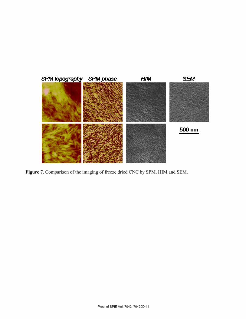
Figure 7. Comparison of the imaging of freeze dried CNC by SPM, HIM and SEM.
Proc. of SPIE Vol. 7042 70420D-11

In: Instrumentation, metrology and Standards and Technology II, edited by Michael T. Postek, John A Allgair, Proc. Of SPIE Vol. 7042, 70420D, (2008)