cell-phone operated land rover - xpertsolver · 2016-10-17 · control of robot involves three...
TRANSCRIPT
Cell-Phone Operated Land Rover
Page 1
XpertSolver.com

XpertSolver.com
INDEX Page No.
1. PREFACE
A) INTRODUCTION………………………………………………………
B) HISTORY……………………………………………………………………………..
C) TECHNOLOGY USED (DTMF SIGNALLING)………………………
2. DESIGN OF THE PROJECT
A) PRELIMINARY DESIGN
i) BLOCK DIAGRAM…………………………………………….
ii) COMPONENTS USED……………………………………
iii) CIRCUIT DIAGRAM…………………………………………..
B) PROBLEMS ENCOUNTERED………………………………………...
C) FINAL DESIGN
i) PCB LAYOUT………………………………………………
ii) PROGRAM CODE……………………………………..
iii) FLOWCHART……………………………………………..
Page 5
XpertSolver.com
D) SOFTWARES USED
i) PINACAL…………………………………………………….
ii) ISP Programmer........................................................................
3. SCOPE OF THE PROJECT
1. APPLICATIONS…………………………………………….. 2. ADVANTAGES……………………………………………... 3. DISADVANTAGES…………………………………………. 4. FURTHER IMPROVEMENTS & FUTURE SCOPE………...
4. BIBLOGYAPHY…..…………………………
5. DATASHEETS…………………………………… Page 6
XpertSolver.com
ACKNOWLEDGEMENT
We feel profound pleasure in bringing out this projects report for which we have to go from pillar to post to make it a reality. This project w o r k reflects cont r ibu t ions of many people with whom we had long discussions and without which it would not have been possible. We must first of all, express our heartiest gratitude to respected Miss.A.R.Kulkarni of D ept of EJ for providing us all r e q u i r e d guidance to complete project.
It would be unfair if we do not mention the invaluable contribution and timely co-operation extended to us by staff member of our department. And especially we can never forget the most worthy advices given by Mr.A.S.Kadam (H.O.D., Dept of E.J), that would help us the entire lifetime.
Last but not the least we express our sincere
thanks to the institute Terna Polytechnic K o p a r k h a i r n e N a v i M u m b a i for providing such a platform for implementing the ideas in our mind.
Page 7 XpertSolver.com
Abstract Conventionally, wireless controlled robots user circuits, which have a drawback of limited working range, limited frequency range and limited control. Use of mobile phones for robotic control can overcome these limitations. It provides the advantages of robust control, working range as large as the coverage area of the service provider, no interference with other controllers and up to twelve controls.
Although, the apperanceand capabilities of robot vary vastly, all robots share the feature of a mechanical, movables structure under some form of control. The control of robot involves three distent phases: perception, processing, action. Generally, the preceptors are sensors mounted on the robot, processing is done by the on board microcontroller and the task is performed using motors or with some other actuators.
In the project the robot is controlled by a mobile phone that makes a call to the mobile phone attached to the robot. In the course of a call, if any button is pressed a tone corresponding to the button pressed is heard at the other end called ‘Dual Tone Multiple frequency’ (DTMF) tone. The robot receives these tones with help of phone stacked in the robot. The received tone is processed by the microcontroller with the help of DTMF decoder ic cm8870 .these ic sends a signals to the the motor driver ic l293d which derives the motor forward,revarse…etc
Page 8
XpertSolver.com
INTRODUCTION
Page 9 XpertSolver.com
INTRODUCTION :
Radio control (often abbreviated to R/C or simply RC) is the use of radio signals to remotely control a device. The term is used frequently to refer to the control of model vehicles from a hand-held radio transmitter. Industrial, military, and scientific research organizations make [traffic] use of radio-controlled vehicles as well.
A remote control vehicle is defined as any mobile device that is controlled by a means that does not restrict its motion with an origin external to the device. This is often a radio control device, cable between control and vehicle, or an infrared controller. A remote control vehicle (Also called as RCV) differs from a robot in that the RCV is always controlled by a human and takes no positive action autonomously.
One of the key technologies which underpin this field is that of remote vehicle control. It is vital that a vehicle should be capable of proceeding accurately to a target area; maneuvering within that area to fulfill its mission and returning equally accurately and safely to base.
Page1 0 XpertSolver.com
Recently, Sony Ericsson released a remote control car that could be controlled by any Bluetooth cell phone. Radio is the most popular because it does not require the vehicle to be limited by the length of the cable or in a direct line of sight with the controller (as with the infrared set-up). Bluetooth is still too expensive and short range to be commercially viable.
Page1 1 XpertSolver.com
HISTORY
Page 1 2 XpertSolver.com
HISTORY OF REMOTE CONTROLLED VEHICLES:
The First Remote Control Vehicle I
Precision Guided Weapon :
This propeller-driven radio controlled boat, built by Nikola Tesla in 1898, is the original prototype of all modern-day uninhabited aerial vehicles and precision guided weapons. In fact , all remotely operated vehicles in air, land or sea. Powered by lead-acid batteries and an electric drive motor, the vessel was designed to be maneuvered alongside a target using instructions received from a wireless remote- control transmitter. Once in position, a command would be sent to detonate an explosive charge contained within the boat!s forward compartment. The weapon!s guidance system incorporated a secure communications link between the pilot!s controller and the surface-running torpedo in an effort to assure that control could be maintained even in the presence of electronic countermeasures. To learn more about Tesla!s system for secure wireless communications and his pioneering implementation of the electronic logic-gate circuit read ‘Nikola Tesla — Guided Weapons & Computer Technology’, Tesla Presents Series Part 3, with commentary by Leland Anderson.
Page 13XpertSolver.com
Use of Remote Controlled Vehicles During World War II :
During World War II in the European Theater the U.S. Air Force experimented with three basic forms radio- control guided weapons. In each case, the weapon would be directed to its target by a crew member on a control plane. The first weapon was essentially a standard bomb fitted with steering controls. The next evolution involved the fitting of a bomb to a glider airframe, one version, the GB-4 having a TV camera to assist the controller with targeting. The third class of guided weapon was the remote controlled B-17.
It!s known that Germany deployed a number of more advanced guided strike weapons that saw combat before either the V-1 or V-2. They were the radio-controlled Henschel!s Hs 293A and Ruhrstahl!s SD1400X, known as ’Fritz X,’ both air-launched, primarily against ships at sea.
Page 14XpertSolver.com
TECHNOLOGY USED
Page 1 5 XpertSolver.com
TECHNOLOGY USED :
Dual-Tone Multi-Frequency (DTMF)
Dual-tone multi-frequency (DTMF) signaling is used for telecommunication signaling over analog telephone lines in the voice-frequency band between telephone handsets and other communications devices and the switching center. The version of DTMF used for telephone tone dialing is known by the trademarked term Touch-Tone (canceled March 13, 1984), and is standardized by ITU-T Recommendation Q.23. It is also known in the UK as MF4. Other multi-frequency systems are used for signaling internal to the telephone network.
As a method of in-band signaling, DTMF tones were also used by cable television broadcasters to indicate the start and stop times of local commercial insertion points during station breaks for the benefit of cable companies. Until better out-of-band signaling equipment was developed in the 1990s, fast, unacknowledged, and loud DTMF tone sequences could be heard during the commercial breaks of cable channels in the United States and elsewhere.
Page 1 6 XpertSolver.com
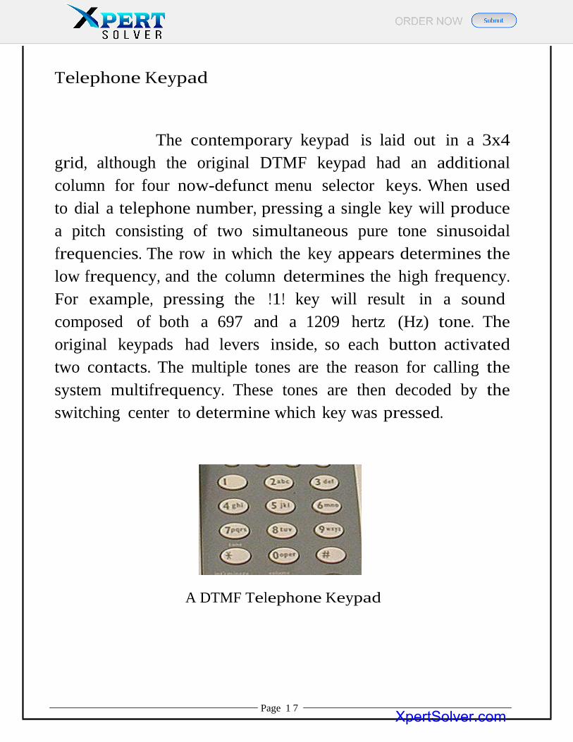
Telephone Keypad
The contemporary keypad is laid out in a 3x4 grid, although the original DTMF keypad had an additional column for four now-defunct menu selector keys. When used to dial a telephone number, pressing a single key will produce a pitch consisting of two simultaneous pure tone sinusoidal frequencies. The row in which the key appears determines the low frequency, and the column determines the high frequency. For example, pressing the !1! key will result in a sound composed of both a 697 and a 1209 hertz (Hz) tone. The original keypads had levers inside, so each button activated two contacts. The multiple tones are the reason for calling the system multifrequency. These tones are then decoded by the switching center to determine which key was pressed.
A DTMF Telephone Keypad
Page 1 7 XpertSolver.com
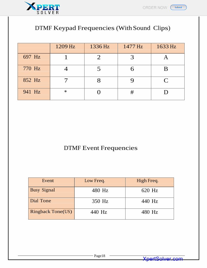
DTMF Keypad Frequencies (With Sound Clips) 1209 Hz 1336 Hz 1477 Hz 1633 Hz
697 Hz 1 2 3 A
770 Hz 4 5 6 B
852 Hz 7 8 9 C
941 Hz * 0 # D
DTMF Event Frequencies
Event Low Freq. High Freq.
Busy Signal 480 Hz 620 Hz
Dial Tone 350 Hz 440 Hz
Ringback Tone(US) 440 Hz 480 Hz
Page18 XpertSolver.com
Tones #, *, A, B, C, and D
The engineers had envisioned phones being used to access computers, and surveyed a number of companies to see what they would need for this role. This led to the addition of the number sign (#, sometimes called !octothorpe! in this context) and asterisk or ’star’ (*) keys as well as a group of keys for menu selection: A, B, C and D. In the end, the lettered keys were dropped from most phones, and it was many years before these keys became widely used for vertical service codes such as *67 in the United States and Canada to suppress caller ID.
The U.S. military also used the letters, relabeled, in their now defunct Autovon phone system. Here they were used before dialing the phone in order to give some calls priority, cutting in over existing calls if need be. The idea was to allow important traffic to get through every time. The levels of priority available were Flash Override (A), Flash (B), Immediate (C), and Priority (D), with Flash Override being the highest priority.
Page 19XpertSolver.com
PRLIMINARY DESIGN
Page 2 0 XpertSolver.com
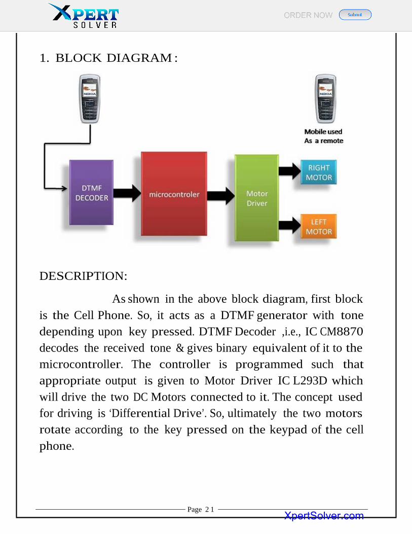
1. BLOCK DIAGRAM :
DESCRIPTION:
As shown in the above block diagram, first block is the Cell Phone. So, it acts as a DTMF generator with tone depending upon key pressed. DTMF Decoder ,i.e., IC CM8870 decodes the received tone & gives binary equivalent of it to the microcontroller. The controller is programmed such that appropriate output is given to Motor Driver IC L293D which will drive the two DC Motors connected to it. The concept used for driving is ‘Differential Drive’. So, ultimately the two motors rotate phone.
according to the key pressed on the keypad of the cell
Page 2 1 XpertSolver.com
100k 2 10k 5 330k 1
CM 8870 1 Atmega16 1 74ls04 1 L293D NE 1 L7805 CV 1
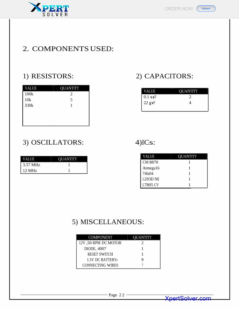
2. COMPONENTS USED:
1) RESISTORS: 2) CAPACITORS:
VALUE QUANTITY VALUE QUANTITY 0.1 uF 2 22 pF 4
3) OSCILLATORS: 4)ICs:
VALUE QUANTITY 3.57 MHz 1 12 MHz 1
VALUE QUANTITY
5) MISCELLANEOUS:
COMPONENT QUANTITY 12V ,50 RPM DC MOTOR 2
DIODE, 4007 1 RESET SWITCH 1 1.5V DC BATTERYs 9
CONNECTING WIRES 7
Page 2 2 XpertSolver.com
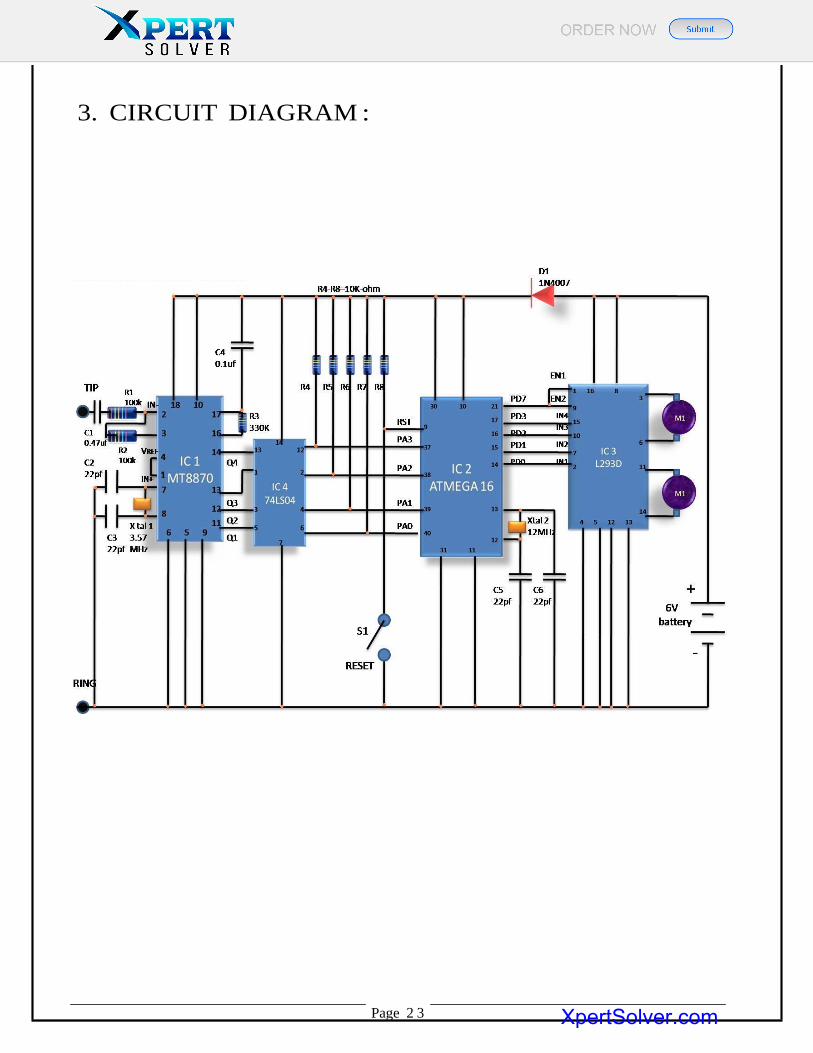
3. CIRCUIT DIAGRAM :
Page 2 3
XpertSolver.com

XpertSolver.com
PROBLEMS
ENCOUNTERED
Page 2 6 XpertSolver.com
PROBLEMS FACED :
Although the concept & design of the project seemed perfect, there were some problems faced while actual implementation:
1. Connecting HandsFree of cell phone to DTMF decoder IC input:
There were several types of HandsFree cords
available in the market, the right one had to be chosen from them. Several ways to break up the cords and connect them to the input of IC 8870 were tried & some were newly developed by us (e.g. Connecting Audio Jack of PC!s speakers to the cell phone with help of an extender).
Solution: Finally HandsFree cord!s !Earplugs! were
removed & resulting set of wires were connected in an appropriate manner to the Decoder IC!s input.
Page 2 7 XpertSolver.com
2. Selection of Mobile Phone:
At first, latest cell phone like Nokia 5700, N-series were tried. But they couldn!t give any output. Several cell phones were tested with their respective Hansfree cords.
Solution: The older version phones like Nokia 1100,Nokia
2300 were found to be more suitable for the purpose. Finally Nokia 1100 was used.
Page 28XpertSolver.com
FINAL DESIGN
Page 2 9 XpertSolver.com
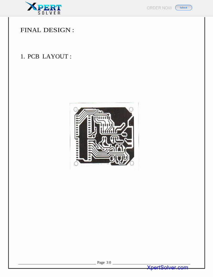
FINAL DESIGN : 1. PCB LAYOUT :
Page 3 0 XpertSolver.com

XpertSolver.com

XpertSolver.com
2. CIRCUIT DESCRIPTION :
The important components of this robot are a DTMF decoder, microcontroller and motor driver.
A CM8870 series DTMF decoder is used here. All types of the CM8870 series use digital counting techniques to detect and decode all the 16 DTMF tone pairs into a 4-bit code output. The built-in dial tone rejection circuit eliminates the need of pre-filtering.
When the input signals are given at pins 1(IN+) & 2(IN-) , a differential input configuration is recognized to be effective, the correct 4-bit decode signal of the DTMF tone is transferred to (pin11) through (pin14) outputs. The pin11 to pin14 of DTMF decoder are connected to the pins of microcontroller (P1.4 to P1.7).
The atmega16 is a 8-bit m i c r o co n t r o l , has 64 kB Flash microcontroller with 1 kB RAM. it provides the following features: 64 kB of on-chip Flash program memory with ISP (In-System Programming) and IAP (In-Application Programming), Four 8-bit I/O ports with three high-current Port 1 pins (16 mA each),Three 16-bit timers/counters.
Page 2 4 XpertSolver.com
Outputs from port pins P0.0 through P0.3 and P0.7 of the microcontroller are fed to the inputs IN1 through IN4 and enable pins (EN1 and EN2) of motor driver L293D IC, respectively to drive two geared dc motors. Switch S1 is used for manual reset. The microcontroller output is not sufficient to drive the dc motors, so current drivers are required for motor rotation.
The L293D is a quad, high-current, half-h driver designed to provide bidirectional drive currents of up to 600mA at voltages from 4.5V to 36V. It makes it easier to drive the dc motors. The L293D consists of four drivers. Pins IN1 through IN4 and OUT1 through OUT4 are the input and output pins, respectively of driver 1 through driver 4. Drivers 1 and 2, and driver 3 and 4 are enabled by enable pin 1(EN1) and pin 9 (EN2), respectively. When enable input EN1 (pin1) is high, drivers 1 and 2 are enabled and the outputs corresponding to their inputs are active. Similarly, enable input EN2 (pin9) enables drivers 3 and 4.
The motors are rotated according to the status of IN1 to IN4 pins of L293D which in turn are depending on output pins of microcontroller, viz., P0.0 - P0.3.
Page 25XpertSolver.com
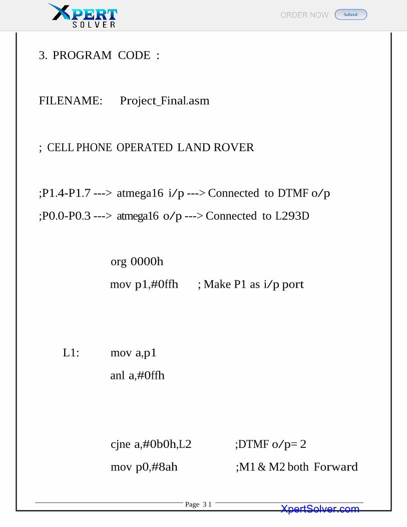
3. PROGRAM CODE :
FILENAME: Project_Final.asm
; CELL PHONE OPERATED LAND ROVER
;P1.4-P1.7 ---> atmega16 i/p ---> Connected to DTMF o/p ;P0.0-P0.3 ---> atmega16 o/p ---> Connected to L293D
org 0000h
mov p1,#0ffh ; Make P1 as i/p port
L1: mov a,p1
anl a,#0ffh
cjne a,#0b0h,L2 ;DTMF o/p= 2
mov p0,#8ah ;M1 & M2 both Forward
Page 3 1 XpertSolver.com
ljmp L1
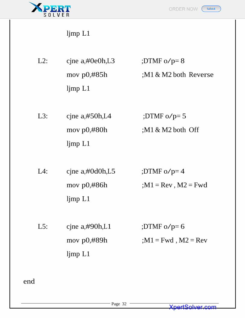
L2: cjne a,#0e0h,L3 ;DTMF o/p= 8
mov p0,#85h ;M1 & M2 both Reverse
ljmp L1
L3: cjne a,#50h,L4 ;DTMF o/p= 5
mov p0,#80h ;M1 & M2 both Off
ljmp L1
L4: cjne a,#0d0h,L5 ;DTMF o/p= 4
mov p0,#86h ;M1 = Rev , M2 = Fwd
ljmp L1
L5: cjne a,#90h,L1 ;DTMF o/p= 6
mov p0,#89h ;M1 = Fwd , M2 = Rev
ljmp L1
end
Page 32 XpertSolver.com
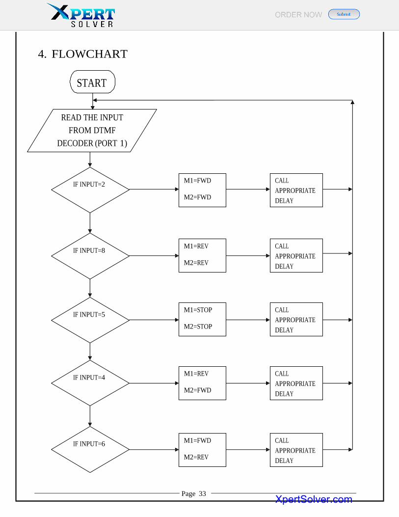
4. FLOWCHART
START
READ THE INPUT FROM DTMF
DECODER (PORT 1)
IF INPUT=2 M1=FWD M2=FWD
CALL APPROPRIATE DELAY
IF INPUT=8 M1=REV M2=REV
CALL APPROPRIATE DELAY
IF INPUT=5 M1=STOP M2=STOP
CALL APPROPRIATE DELAY
IF INPUT=4 M1=REV M2=FWD
CALL APPROPRIATE DELAY
IF INPUT=6 M1=FWD M2=REV
CALL APPROPRIATE DELAY
Page 33 XpertSolver.com
SOFTWARES USED
Page34 XpertSolver.com
APPLICATIONS
Page 4 0
XpertSolver.com
APPLICATIONS :
Scientific Remote control vehicles have various scientific
uses including hazardous environments, working in the deep ocean , and space exploration. The majority of the probes to the other planets in our solar system have been remote control vehicles, although some of the more recent ones were partially autonomous. The sophistication of these devices has fueled greater debate on the need for manned spaceflight and exploration. The Voyager I spacecraft is the first craft of any kind to leave the solar system. The martian explorers Spirit and Opportunity have provided continuous data about the surface of Mars since January 3, 2004.
Military and Law Enforcement
Military usage of remotely controlled military vehicles dates back to the first half of 20th century. Soviet Red Army used remotely controlled Teletanks during 1930s in the Winter War and early stage of World War II. There were also
Page 4 1 XpertSolver.com
remotely controlled cutters and experimental remotely controlled planes in the Red Army.
Remote control vehicles are used in law enforcement and military engagements for some of the same reasons. The exposure to hazards are mitigated to the person who operates the vehicle from a location of relative safety. Remote controlled vehicles are used by many police department bomb-squads to defuse or detonate explosives. See Dragon Runner, Military robot.
Unmanned Aerial Vehicles (UAVs) have undergone a dramatic evolution in capability in the past decade. Early UAV!s were capable of reconnaissance missions alone and then only with a limited range. Current UAV!s can hover around possible targets until they are positively identified before releasing their payload of weaponry. Backpack sized UAV!s will provide ground troops with over the horizon surveillance capabilities.
Page 4 2 XpertSolver.com
Search and Rescue
UAVs will likely play an increased role in search and rescue in the United States. This was demonstrated by the successful use of UAVs during the 2008 hurricanes that struck Louisiana and Texas.
Recreation and Hobby
See Radio-controlled model. Small scale remote control vehicles have long been popular among hobbyists. These remote controlled vehicles span a wide range in terms of price and sophistication. There are many types of radio controlled vehicles. These include on-road cars, off-road trucks, boats, airplanes, and even helicopters. The ’robots’ now popular in television shows such as Robot Wars, are a recent extension of this hobby (these vehicles do not meet the classical definition of a robot; they are remotely controlled by a human). Radio-controlled submarine also exist.
Page 43 XpertSolver.com
FURTHER IMROVEMENTS
FUTURE SCOPE
Page 4 4 XpertSolver.com
FURTHER IMPROVEMENTS & FUTURE SCOPE : 1. IR Sensors:
IR sensors can be used to automatically detect & avoid obstacles if the robot goes beyond line of sight. This avoids damage to the vehicle if we are maneuvering it from a distant place.
2. Password Protection:
Project can be modified in order to password protect the robot so that it can be operated only if correct password is entered. Either cell phone should be password protected or necessary modification should be made in the assembly language code. This introduces conditioned access & increases security to a great extent.
Page 4 5 XpertSolver.com
3. Alarm Phone Dialer:
By replacing DTMF Decoder IC CM8870 by a !DTMF Transceiver IC’ CM8880, DTMF tones can be generated from the robot. So, a project called !Alarm Phone Dialer! can be built which will generate necessary alarms for something that is desired to be monitored (usually by triggering a relay). For example, a high water alarm, low temperature alarm, opening of back window, garage door, etc.
When the system is activated it will call a number of programmed numbers to let the user know the alarm has been activated. This would be great to get alerts of alarm conditions from home when user is at work.
4. Adding a Camera:
If the current project is interfaced with a camera (e.g. a Webcam) robot can be driven beyond line-of-sight & range becomes practically unlimited as GSM networks have a very large range.
Page 46 XpertSolver.com

BIBLIOGRAPHY
Page 4 7XpertSolver.com
BIBLIOGRAPHY:
1. Wikipedia - The free encyclopedia
2. http://www.8051projects.info/
3. http://www.instructables.com/
4. cell phone operated land rover Electronics For You’ Magazine , Edition (july 2008)
5. “DTMF Tester” , ‘Electronics For You’ Magazine , Edition (June 2003)
6. http://www.alldatasheet.com/
7. http://www.datasheet4u.com/
8. http://www.datasheetcatalog.com/
Page 4 8 XpertSolver.com

XpertSolver.com
DATASHEETS
Page 49
XpertSolver.com
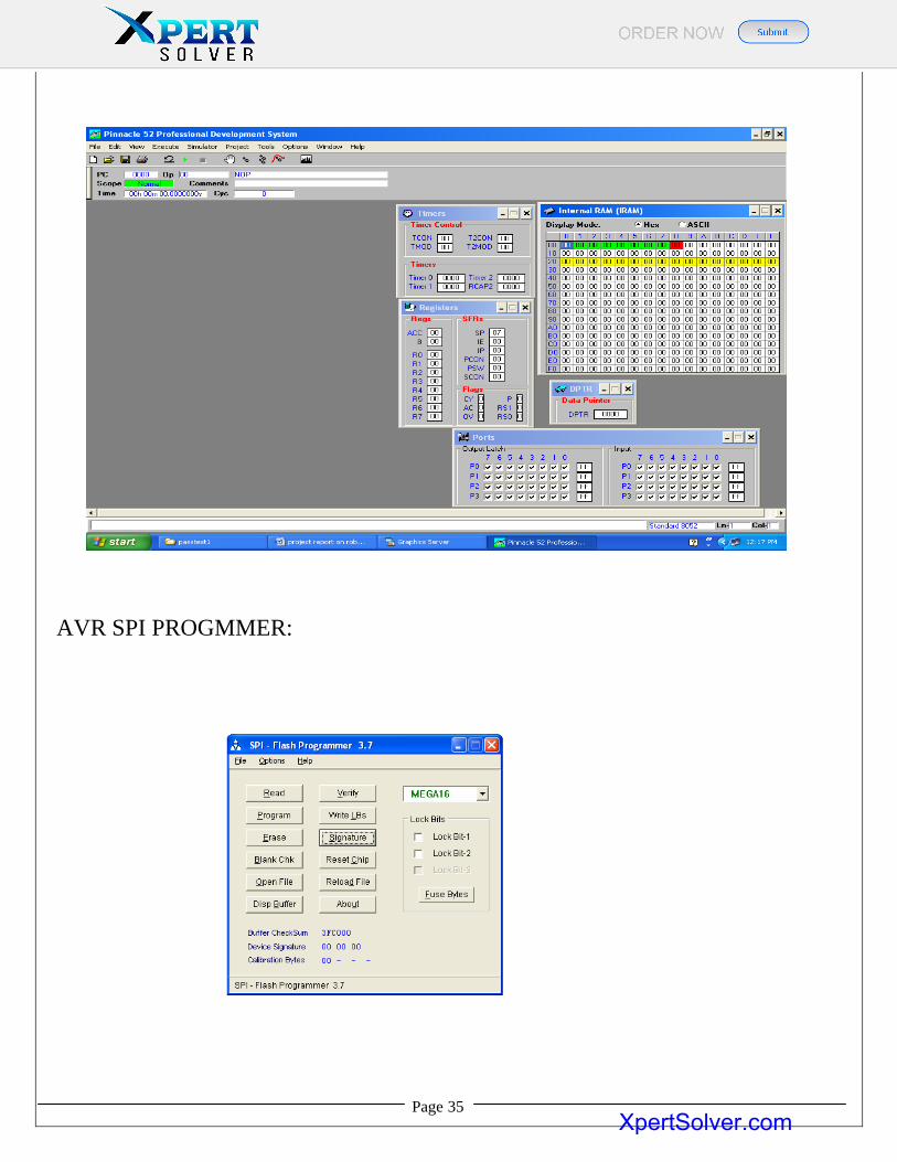
PINNACLE ENVIROMENT:
AVR SPI PROGMMER:
Page 35
XpertSolver.com
ADVANTAGES
Page 36
XpertSolver.com
1. Wireless control 2. Surveillance System. 3. Vehicle Navigation with use of 3G technology. 3. Takes in use of the mobile technology which is almost available everywhere. 4. This wireless device has no boundation of range and can be controlled as far as network of cell phone
Page 37
XpertSolver.com
DISADVANTAGES
page38
XpertSolver.com
1. Cell phone bill. 2. Mobile batteries drain out early so charging problem. 3. Cost of project if Cell phone cost included.
4. Not flexible with all cell phones as only a particular ,cell phone whose earpiece is attached can only be used
Page 39
XpertSolver.com

Page 50
XpertSolver.com

XpertSolver.com