ceg 883 design sheet1
TRANSCRIPT
7/31/2019 CEG 883 Design Sheet1
http://slidepdf.com/reader/full/ceg-883-design-sheet1 1/16
DESIGNED BY 119052016
PAGE NO 1
JOB REF : CEG 883 DATE 2012
REF OUTPUT
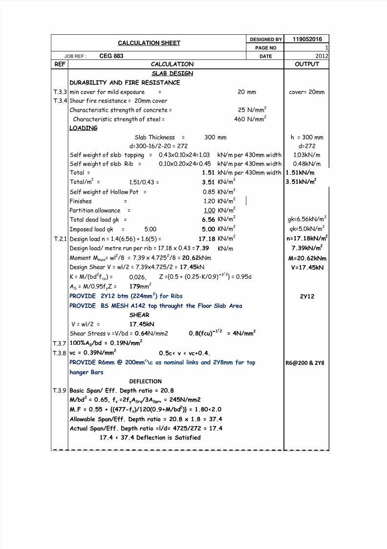
DURABILITY AND FIRE RESISTANCE
T.3.3 min cover for mild exposure = 20 mm cover= 20mm
T.3.4 1hour fire resistance = 20mm cover
Characteristic strength of concrete = 25 N/mm2
Characteristic strength of steel = 460 N/mm2
LOADING
300 mm h = 300 mm
d=300-16/2-20 = 272 d=272
Self weight of slab topping = 0.43x0.10x24=1.03 kN/m per 430mm width 1.03kN/m
Self weight of slab Rib = 0.10x0.20x24=0.45 kN/m per 430mm width 0.48kN/m
Total = 1.51 kN/m per 430mm width 1.51kN/m
Total/m2 = 1.51/0.43 = 3.51 KN/m2 3.51kN/m2
Self weight of Hollow Pot = 0.85 KN/m2
Finishes = 1.20 KN/m2
Partition allowance = 1.00 KN/m2
Total dead load gk = 6.56 KN/m2 gk=6.56kN/m2
Imposed load qk = 5.00 5.00 KN/m2 qk=5.0kN/m2
T.2.1 Design load n = 1.4(6.56) + 1.6(5) = 17.18 KN/m2 n=17.18kN/m2
Design load/ metre run per rib = 17.18 x 0.43 =7.39 KN/m 7.39kN/m2
Moment Mmax= wl2/8 = 7.39 x 4.7252/8 = 20.62kNm M=20.62kNm
Design Shear V = wl/2 = 7.39x4.725/2 = 17.45kN V=17.45kN
K = M/(bd2fcu) = 0.026, Z ={0.5 + (0.25-K/0.9)^1 2} = 0.95d
AS = M/0.95f yZ = 179mm
2
PROVIDE 2Y12 btm (224mm2) for Ribs 2Y12
PROVIDE BS MESH A142 top throught the Floor Slab Area
SHEAR
V = wl/2 = 17.45kN
Shear Stress v =V/bd = 0.64N/mm2 0.8(fcu)^1 2 = 4N/mm2
T.3.7 100%AS/bd = 0.19N/mm2
T.3.8 vc = 0.39N/mm20.5c< v < vc+0.4.
PROVIDE R6mm @ 200mmc\c as nominal links and 2Y8mm for top R6@200 & 2Y8
hanger Bars
DEFLECTION
T.3.9 Basic Span/ Eff. Depth ratio = 20.8
M/bd2 = 0.65, fs =2fyASrq/3ASprv = 245N/mm2
M.F = 0.55 + {(477-fs)/120(0.9+M/bd2)} = 1.80<2.0
Allowable Span/Eff. Depth ratio = 20.8 x 1.8 = 37.4
Actual Span/Eff. Depth ratio =l/d= 4725/272 = 17.4
17.4 < 37.4 Deflection is Satisfied
CALCULATION SHEET
CALCULATION
SLAB DESIGN
Slab Thickness =

7/31/2019 CEG 883 Design Sheet1
http://slidepdf.com/reader/full/ceg-883-design-sheet1 2/16
BEAM DESIGNS
Beam Height --------- 550mm Cover to Reinforcement--25mm
Beam Width---------- 225mm Diameter of Main Bars----20mm
Height of Flange---- 100mm Diameter of links----------10mm
Fcu-------------------- 25N/mm2, Assummed Height of Walls-----------3000mm
FY-------------------- 460N/mm
2
225mm Hollow Blocks Unit Weight ----------- 2.87kN/m2
Wall Finishes- both sides ---------------------- 0.60kN/m2
Effective Depth d = 550 -20/2 - 25 - 10 = 505mm
LOADING
Beam Self Weight ---0.225 x (0.55-0.100) x 24 x 1.4 = 3.402 KN/m
Wall Loads and Finishes ---2.87 x 3 x 1.4 x 0.6 = 7.23kN/m
M ain Loads from Slab---- 17.18 x 4.725/2 = 40.59kN/m
Loads on Beams parallel to Slab span/metre---=17.18kN/m
for Beams A(1-6) and D(1-6)
self weight ----------------------- 3.4 kN/m
walls and finishes--------------------- 7.23 kN/m
load from slab-------------------------- 17.18 kN/m
27.81 kN/m
for Beams B(1-6) and C(1-6)
self weight ----------------------- 3.4 kN/m
walls and finishes--------------------- 7.23 kN/m
load from slab-------------------------- 17.18 kN/m
27.81 kN/m
for Beams 1(A-B) and 1(C-D)
self weight ----------------------- 3.4 kN/m
walls and finishes--------------------- 7.23 kN/m
load from slab-------------------------- 17.18 kN/m
27.81 kN/m
Please refer to Analysis sheets for the Bending Moments, Shear Forces and
Deflection Diagrams

7/31/2019 CEG 883 Design Sheet1
http://slidepdf.com/reader/full/ceg-883-design-sheet1 3/16

7/31/2019 CEG 883 Design Sheet1
http://slidepdf.com/reader/full/ceg-883-design-sheet1 4/16
One way slab Span = 1.8 m
KN/m
1.8 m
M = 0.1 x x 1.82 KNm
qua.
qua.
Cl. 3.

7/31/2019 CEG 883 Design Sheet1
http://slidepdf.com/reader/full/ceg-883-design-sheet1 5/16

7/31/2019 CEG 883 Design Sheet1
http://slidepdf.com/reader/full/ceg-883-design-sheet1 6/16

7/31/2019 CEG 883 Design Sheet1
http://slidepdf.com/reader/full/ceg-883-design-sheet1 7/16

7/31/2019 CEG 883 Design Sheet1
http://slidepdf.com/reader/full/ceg-883-design-sheet1 8/16

7/31/2019 CEG 883 Design Sheet1
http://slidepdf.com/reader/full/ceg-883-design-sheet1 9/16
DESIGNED B
PAGE NO
JOB REF : CEG 883 DATE
REF
Beam A(1-6) and D(1-6)
T.3.5 Using Table 3.5 of BS 8110 to estimate the Moments and Shears since both theLoads and the Spans are Uniform
For Support Moments,
M1 = M6 = 0.0kNm,
M2 = M5 = -0.11FL(at first interior supports)
F=Design Load n x Span = 17.18 x 4.725 = 81.18 KN
M2= M5 = -0.11FL = -0.11 X81.18 X 4.725 =-42.19 kNm
the Negatve sign indicates that it is a hogging Moment
M3 =M4=-0.08FL( at interior Supports)=-0.08x81.18x4.725=-30.69 kNm
T.3.5 For Span Moments,
M1-2=M5-6 = 0.09FL(Near middle of end spans)=0.09x81.18.4.725=34.52kNm
M2-3=M4-5 = 0.07FL(at middle of interior spans)=0.07x81.18x4.725=26.85kNm
T.3.5 For Support Shears,
V1 = V6 = 0.45F(at outer support) = 0.45 x 81.18 = 36.53kN
V2 = V5 = 0.6F(at first interior support) = 0.6 x 81.18 =48.71kN
V3 = V4 = 0.55F(at interior support) = 0.55 x 81.18 =45.01kN
Beam A(1-6) and D(1-6)
Support Moments:M2 = M5=42.19kNm,M3 =M4=30.69kNm, Mmax=42.19kNm
K = M/(bfd2fcu) = 0.029, Z ={0.5 + (0.25-K/0.9)^1 2} = 0.95d
AS = M/0.95f yZ = 201mm2
PROVIDE 2Y16 top (402mm2)
Span Moments,M1-2=M5-6=34.52kNm,M2-3=M4-5 = 26.85kNm,Mmax=34.52kNm
K = M/(bd2fcu) = 0.006, Z ={0.5 + (0.25-K/0.9)^1 2} = 0.95d
AS = M/0.95f yZ = 165mm2
PROVIDE 2Y16 btm (402mm2)
SHEAR
V2 = V5 = 48.71kN
Shear Stress v =V/bd = 0.35N/mm2 0.8(fcu)^1 2 = 4N/mm2
T.3.7 100%AS/bd = 0.19N/mm2
T.3.8 vc = 0.20N/mm20.5c< v < vc+0.4.
PROVIDE Minimum shear reinforcement throughout the length of the beam
SV = 0.75d = 304mm
PROVIDE 2 legs of R10mm @ 300mmc\c as links throughtout the span
DEFLECTION
T.3.9 Basic Span/ Eff. Depth ratio = 20.8
M/bd2 = 0.15, fs =2fyASrq/3ASprv = 126N/mm2
CALCULATION SHEET
CALCULATION
BEAMS DESIGN

7/31/2019 CEG 883 Design Sheet1
http://slidepdf.com/reader/full/ceg-883-design-sheet1 10/16
M.F = 0.55 + {(477-fs)/120(0.9+M/bd2)} = 3.1>2.0
Allowable Span/Eff. Depth ratio = 20.8 x 2 = 41.6
Actual Span/Eff. Depth ratio =l/d= 4725/505 = 9.4
9.4 < 41.6 Deflection is Satisfied
Beam B(1-6) and C(1-6)
Support Moments: Mmax=65.4kNm bw=225mm
K = M/(bd2fcu) = 0.046, Z ={0.5 + (0.25-K/0.9)^1 2} = 0.89d
AS = M/0.95f yZ = 246mm2
PROVIDE 2Y16 top (402mm2)
Span Moments,Mmax=48.3kNm bf = 887mm
K = M/(bd2fcu) = 0.009, Z ={0.5 + (0.25-K/0.9)^1/2} = 0.95d
AS = M/0.95f yZ = 165mm2
PROVIDE 2Y16btm (402mm2)
SHEAR
V= 146.1kN
Shear Stress v =V/bd = 1.3N/mm2 0.8(fcu)^1 2 = 4N/mm2
T.3.7 100%AS/bd = 0.35N/mm2
T.3.8 vc = 0.20N/mm2 0.5c< v
PROVIDE Minimum shear reinforcement throughout the length of the beam
SV = 0.75d = 304mm
PROVIDE 2 legs of R10mm @ 300mmc\c as links throughtout the span
DEFLECTION
T.3.9 Basic Span/ Eff. Depth ratio = 20.8
M/bd2 = 0.23, fs =2fyASrq/3ASprv = 188N/mm2
M.F = 0.55 + {(477-fs)/120(0.9+M/bd
2
)} = 2.7>2.0Allowable Span/Eff. Depth ratio = 20.8 x 2 = 41.6
Actual Span/Eff. Depth ratio =l/d= 4725/505 = 9.4
9.4 < 41.6 Deflection is Satisfied
Beam 1(A-B) and 1(C-D)
Support Moments: Mmax=22.5kNm bw=225mm
K = M/(bd2fcu) = 0.017, Z ={0.5 + (0.25-K/0.9)^1/2} = 0.95d
AS = M/0.95f yZ = 107mm2
PROVIDE 2Y16 top (402mm2)
Span Moments,Mmax=237kNm
K = M/(bd2fcu) = 0.056, Z ={0.5 + (0.25-K/0.9)^1/2} = 0.93d
AS = M/0.95f yZ = 1155mm2
PROVIDE 2Y20btm + 3Y16(1231mm2)
SHEAR
V= 163kN
Shear Stress v =V/bd = 1.43N/mm2 0.8(fcu)^1/2 = 4N/mm2
T.3.7 100%AS/bd =1.08N/mm2

7/31/2019 CEG 883 Design Sheet1
http://slidepdf.com/reader/full/ceg-883-design-sheet1 11/16
T.3.8 vc = 0.59N/mm2 0.5c< v
PROVIDE Minimum shear reinforcement throughout the length of the beam
SV = 0.95ASVfy/0.4b = 304mm
PROVIDE 2 legs of R10mm @ 250mmc\c as links throughtout the span
DEFLECTION
T.3.9 Basic Span/ Eff. Depth ratio =16
M/bd2 = 1.4, fs =2fyASrq/3ASprv = 288N/mm2
M.F = 0.55 + {(477-fs)/120(0.9+M/bd2)} = 2.0
Allowable Span/Eff. Depth ratio = 16 x 2 = 32
Actual Span/Eff. Depth ratio =l/d= 6225/505 = 12.3
12.3 <32 Deflection is Satisfied

7/31/2019 CEG 883 Design Sheet1
http://slidepdf.com/reader/full/ceg-883-design-sheet1 12/16
119052016
1
2012
OUTPUT
M=42.19kNm
2Y16TOP
2Y16btm
R10@300

7/31/2019 CEG 883 Design Sheet1
http://slidepdf.com/reader/full/ceg-883-design-sheet1 13/16
use 2.0
M=65.4kNm
3Y16TOP
2Y16btm
R10@300
use 2.0
M=22.5kNm
3Y16TOP
2Y20+3Y16

7/31/2019 CEG 883 Design Sheet1
http://slidepdf.com/reader/full/ceg-883-design-sheet1 14/16

7/31/2019 CEG 883 Design Sheet1
http://slidepdf.com/reader/full/ceg-883-design-sheet1 15/16
ESIGNED B
PAGE NO
JOB REF : CEG 883 DATE
REF
Beam 3(A-D), 4(A-D),5(A-D) ,6(A-D) and 2(A-D)
Support Moments: Mmax=146.9kNm bw=225mm
K = M/(bd2fcu) = 0.033, Z ={0.5 + (0.25-K/0.9)^1/2} = 0.95dAS = M/0.95f yZ = 760mm2
PROVIDE 4Y16 top (804mm2)
Span Moments,Mmax=159.3kNm
K = M/(bd2fcu) = 0.024, Z ={0.5 + (0.25-K/0.9)^1 2} = 0.93d
AS = M/0.95f yZ = 760mm2
PROVIDE 4Y16 btm(804mm2)
SHEAR
V= 177.1kN
Shear Stress v =V/bd = 1.56N/mm
2
0.8(fcu)^
1/2
= 4N/mm
2
T.3.7 100%AS/bd =0.71N/mm2
T.3.8 vc = 0.57N/mm2 0.5c< v
PROVIDE Minimum shear reinforcement throughout the length of the beam
SV = 0.95ASVfy/0.4b = 304mm
PROVIDE 2 legs of R10mm @ 250mmc\c as links throughtout the span
DEFLECTION
T.3.9 Basic Span/ Eff. Depth ratio =20.8
M/bd2 = 1.4, fs =2fyASrq/3ASprv = 290N/mm2
M.F = 0.55 + {(477-fs)/120(0.9+M/bd2)} = 1.45
Allowable Span/Eff. Depth ratio = 20.8 1.45 = 30.2
Actual Span/Eff. Depth ratio =l/d= 6225/505 = 12.3
12.3 <30.22 Deflection is Satisfied
CALCULATION SHEET
CALCULATION

7/31/2019 CEG 883 Design Sheet1
http://slidepdf.com/reader/full/ceg-883-design-sheet1 16/16
119052016
1
2012
OUTPUT
M=146.9kNm
4Y16TOP
4Y16 btm
R10@250