ceen 311: kick scooter project section a team 6...
TRANSCRIPT
CEEN 311:
Kick Scooter Project
Section A Team 6
Instructor:
Dr. Lauren Cooper
Team Members:
Muhammad Akmal Mustaffa Kamal
Joseph Linden Cotchen
Nadozie Okpara
David Van Akkeren
2
Project Overview:
Throughout the course of the semester, students have been learning the typical skills of a standard
Mechanics of Materials class. In addition to the concepts, this course has been centered on project-
based learning (PBL). This learning style takes the techniques learned in class and applies them to solving
real-life problems. Within PBL, it is necessary for the students to design a solution to their specified
project, analyze and solve problems as they arise, work together as a team, and make use of engineering
concepts. This PBL style of learning not only utilizes theory in real life situations but also in the process
helps the student learn and better understand the engineering material.
Objectives:
The project for this course was to design and build a foot-powered scooter out of PVC pipe and fittings.
Teams of four were selected based on self reported strengths and weaknesses. Major objectives of the
project were to develop a fully functional scooter with a break that at a minimum could support a 150 lb
rider by using only PVC structural members and have a minimum factor of safety of two while weighing
less than 14 lbs and able to fit inside a 36” x 36” x 24” envelope. The budget was limited to $40 but the
castors were standardized and provided by the professor. Additional optional objectives were to create
a collapsible scooter as well as developing and employing a real-time strain gauge circuit for the scooter.
The student-designed scooters are to be raced at the end of the semester as part of a viability test as to
whether or not the scooters will function as intended.
Requirements:
1. Safety: The scooter itself must be deemed safe and fit for riding. Scooters with excessive
deformation, the potential for buckling, poor connections, jagged edges, or protruding bolts
will not be allowed to race.
2. Weight Capacity: The scooter must be able to withstand the stress and strain of a 150 – 170
lb rider and feature a minimum factor of safety of 2 in its weakest member or connection.
3. Materials: The scooter must be made of PVC structural members however connections can
utilize metal bolts. Duct tape is not permitted.
4. Weight: The scooter must not exceed 14 lbs.
3
5. Dimensions: The scooter must be able to fit into a 36” x 36” x 24” envelope.
6. Quality: The scooter as presented at the “Scoot Off” must be presentable as a finished
project. This means symmetry and aesthetics are necessary to consider.
7. Foot-powered: A major objective of this assignment was to create a foot-powered scooter.
Any other propulsion system is not allowed.
8. Ride-ability: The scooter must carry the rider in a natural position and be easily balanced.
The rider should be able to traverse varying types of terrain without excessive vibration.
Extra Credit:
1. Collapsibility: Extra points will be awarded to teams with a fully collapsible scooter that can
be easily carried and stowed.
2. Strain Measurement: Extra points will be awarded to teams that generate a strain gage
circuit that, along with LabView, will measure real-time strain of the scooter deck.

4
Budget Tracking:
Cost Table
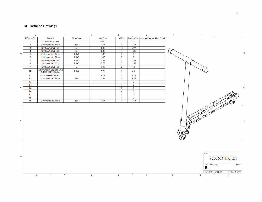
ITEM NO. Description Pipe Size Unit Cost QTY. Total Cost
1 Wheel Assembly $0.00 2 $0.00
2 Unthreaded Pipe 3/4 $1.64 1 $1.64
3 Unthreaded Tee 3/4 $0.33 19 $6.27
4 Unthreaded Tee 3/4 $0.33 4 $1.32
5 Unthreaded Pipe 1 1/2 $1.00 1 $1.00
6 Unthreaded Pipe 1 1/2 $1.00 2 $2.00
7 Unthreaded Tee 1 1/2 $1.54 1 $1.54
8 Unthreaded Cap 1 1/2 $0.78 2 $1.56
9 Unthreaded Tee 2 $2.25 2 $4.50
10 Easy-Align Socket End Class 150
Flange 1 1/2 $7.90 1 $7.90
11 Quick-Release Pin $2.13 1 $2.13
12 Unthreaded Pipe 3/4 $1.64 3 $4.92
13 Fasteners $0.54 1 $0.54
14 Spring $4.54 1 $4.54
Total $39.86
5
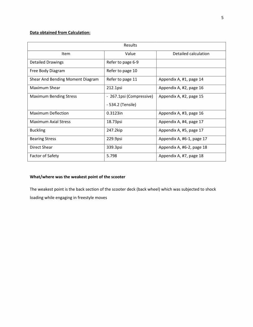
Data obtained from Calculation:
Results
Item Value Detailed calculation
Detailed Drawings Refer to page 6-9
Free Body Diagram Refer to page 10
Shear And Bending Moment Diagram Refer to page 11 Appendix A, #1, page 14
Maximum Shear 212.1psi Appendix A, #2, page 16
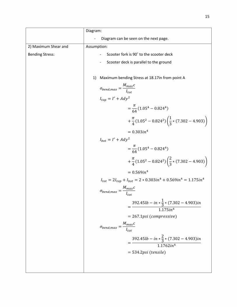
Maximum Bending Stress - 267.1psi (Compressive)
- 534.2 (Tensile)
Appendix A, #2, page 15
Maximum Deflection 0.3123in Appendix A, #3, page 16
Maximum Axial Stress 18.73psi Appendix A, #4, page 17
Buckling 247.2kip Appendix A, #5, page 17
Bearing Stress 229.9psi Appendix A, #6-1, page 17
Direct Shear 339.3psi Appendix A, #6-2, page 18
Factor of Safety 5.798 Appendix A, #7, page 18
What/where was the weakest point of the scooter
The weakest point is the back section of the scooter deck (back wheel) which was subjected to shock
loading while engaging in freestyle moves

6
Drawings:
A) Overall drawing:
1) Initial Idea

7
2) Improvements made after the project poster activity
8
B) Detailed Drawings

9

10
Free Body Diagram:

11
Moment and Shear Diagram
For calculation, refer to Appendix
Mmax = 392.45lb-in V = 37lb
V = Vmax = 113lb
F2 = 37lb
W = 150lb/ft Ffork = 20lb
F1 = 133lb
Mmax = 1150lb-in
9.13in 9.04in 2.96in 9.13in

12
Data obtained from scoot-off, weight-in and deflection activity:
Weight 10.4lb
Deflection 0.277in
Efficiency Score 125%
Scoot-off time 1:13.00s
Scoot Off Performance Analysis:
The scooter did well in the Scoot Off performance. Despite a very competitive environment the scooter
performed better than expected under greater than anticipated forces. The scooter cornered well
around the initial roundabout obstacle and had acceptable clearance while taking turns at speed. The
scooter performed as expected over the cobblestones. Despite noticeable slowing in that section, the
vibration was within reason and likely due to wheel size and hardness. Some deflection of the scooter
deck was noticed by the rider during the competition. Deflection of the steer tube was noted as a
distraction during casual use and created instability when subjected to extreme conditions. Despite
having a functional brake, the rider opted not to use this design feature so its performance is unknown.
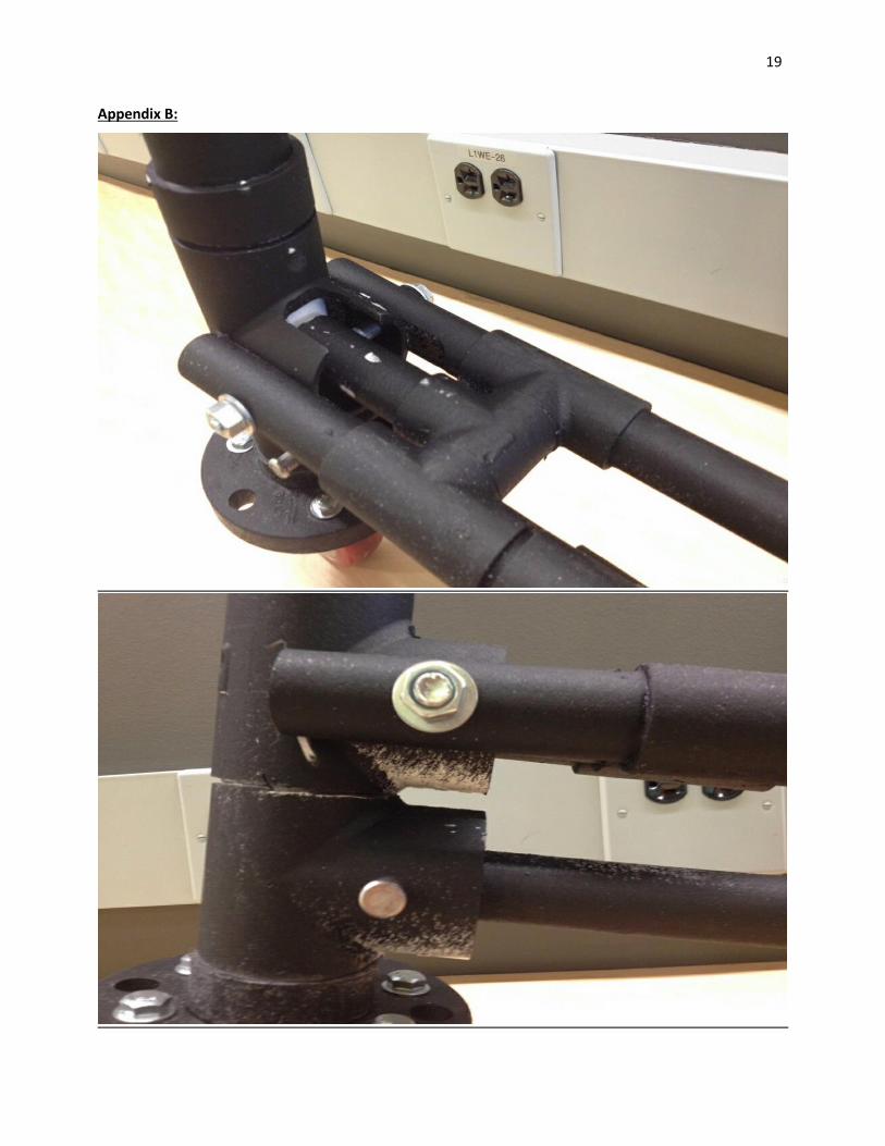
The final time for group 6 was 1:13.00. Following the race, the scooter was subjected to shock loading
while participating in freestyle moves as well as to assess failure strength. The scooter deck eventually
failed in the back section of the deck just prior to the rear wheel. The breakage occurred at the junction
of two of the tee sections in non-linear fractures.
The completed scooter weighted 10.4 lbs and had a deflection of 0.277 inches. The weight was 112% of
the class average and 111.6% of the class' average deflection. The scooter had a structural efficiency
score of 125%. The lower than average scores were due to several factors. When loaded, a moderate
amount of deflection occurred due to the connection of the steer tube to the deck. A higher schedule
PVC or two concentric tubes glued together could have reduced this. Additionally, the length of the deck
was considerably longer than others in the class. The scooter was designed to comfortably carry a 6 ft.
rider while satisfying all technical requirements. If the deck length was reduced to a normalized length the
deflection would have been significantly reduced.
13
Overall Summary:
The process of integrating PBL with Mechanics of Materials concepts by designing a PVC scooter was a
great experience overall. The project encouraged in-depth thinking and helped make the learning
process of the math more meaningful and will help make the overall concepts stay longer in memory.
One of the major issues faced was budgetary constraints. The original design presented during the
prototype presentation was well over the $40 limit. Once the original design’s budget was itemized,
several of the parts were cost prohibitive and that led to scrapping the entire first design. The second
design was drafted with part costs heavily in mind while maintaining the prescribed scooter
requirements.
This project was definitely worth the effort. When groups elect to give ample time for the construction
process, the students use more of the concepts learned in the class than in a standard mid-term testing
structure. By including at least one written problem pairing the scooter project to the material learned
during that week’s class, students could practice and apply their understanding of concepts to real-
world problems just as they will following graduation. This project was a great way to combine all the
topics of Mechanics of Materials into a single project especially in a condensed summer semester.
During a standard length semester, either more requirements should be added to the scooter design or
lighter than average testing should be used in addition to the scooter project.

14
Appendix A:
Item Calculation
1) Moment and Shear
Diagram:
Assumption:
- Scooter fork is 90˚ to the scooter deck
- Scooter deck is parallel to the ground
Calculation:
1) Moment from fork
- To find the internal bending moment at A, use the FBD of
the scooter fork with the cut at point A and find the sum of
the moment at the point of cut.
∑ ( ) ( )
( )
2) Support reactions
- To find By , use the FBD of the scooter deck and find the
sum of moment at point A
∑
( )
( )
- To find Ay , use the FBD of the scooter deck and find the
sum of forces on y-axis
∑
3) Shear diagram
- V=0 when
( )
4) Moment diagram
15
Diagram:
- Diagram can be seen on the next page.
2) Maximum Shear and
Bending Stress:
Assumption:
- Scooter fork is 90˚ to the scooter deck
- Scooter deck is parallel to the ground
1) Maximum bending Stress at 18.17in from point A
( )
( ) (
( ))
( )
( ) (
( ))
( )
( )
( )
( )

16
2) Maximum Shear located at 0in to 9.13in from point A
(
)
(( ) ( ) )
( ) ( )
3) Maximum Deflection:
Assumption:
- Scooter fork is 90˚ to the scooter deck
- Scooter deck is parallel to the ground
By using case #2 in the table attached in references section,
( )
(( )
( ) ( ) )
√
( )
√
Maximum total deflection from calculation is a hint more than the
actual deflection which was measured at 0.277in because of a few
reasons:
1) The load (weight of the person) during the activity was slightly
less than the assumption used in the calculation
2) The calculation did not take into account of the PVC couplings,
tees and connectors.
3) The pipes were consisting of a bunch of short length pipes
instead of three long PVCs.
17
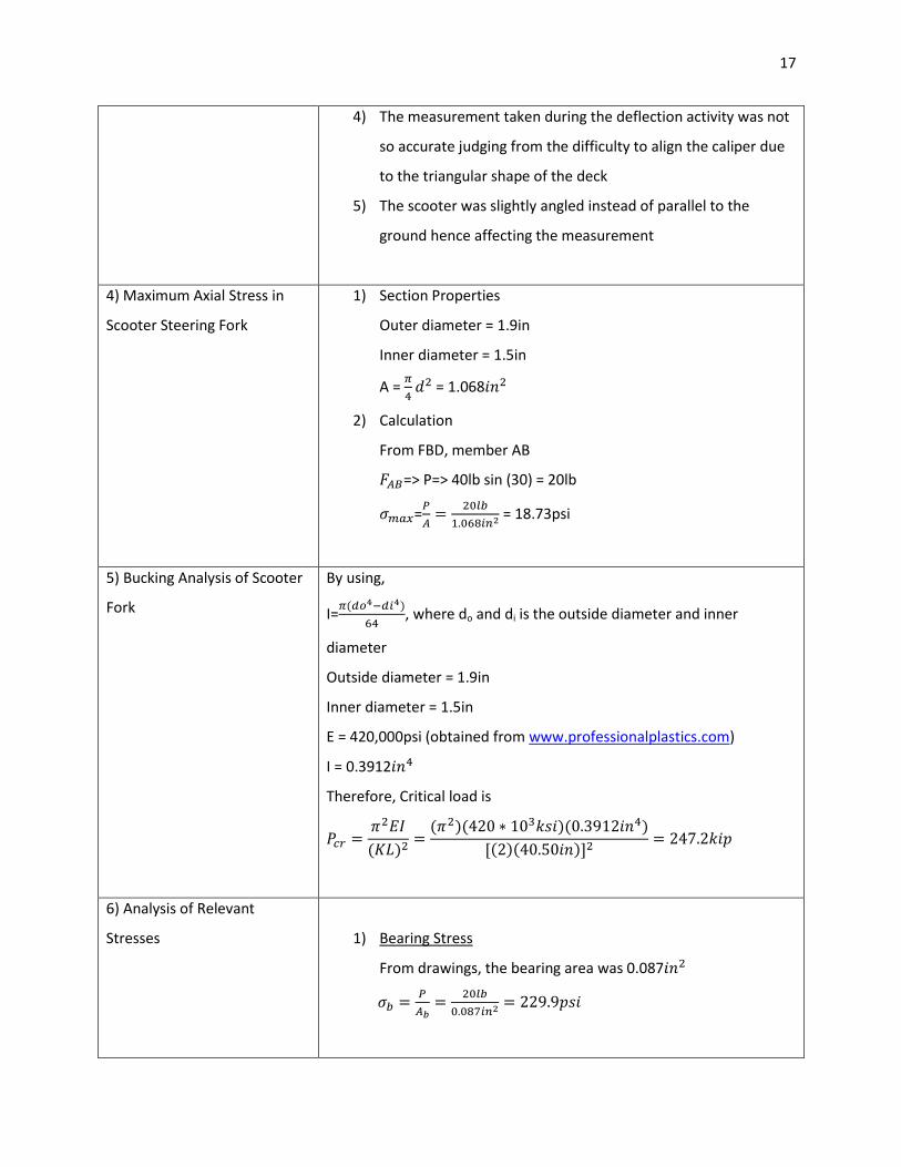
4) The measurement taken during the deflection activity was not
so accurate judging from the difficulty to align the caliper due
to the triangular shape of the deck
5) The scooter was slightly angled instead of parallel to the
ground hence affecting the measurement
4) Maximum Axial Stress in
Scooter Steering Fork
1) Section Properties
Outer diameter = 1.9in
Inner diameter = 1.5in
A =
= 1.068
2) Calculation
From FBD, member AB
=> P=> 40lb sin (30) = 20lb
=
= 18.73psi
5) Bucking Analysis of Scooter
Fork
By using,
I= ( )
, where do and di is the outside diameter and inner
diameter
Outside diameter = 1.9in
Inner diameter = 1.5in
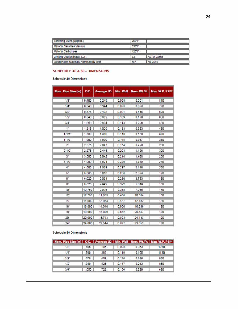
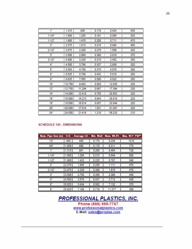
E = 420,000psi (obtained from www.professionalplastics.com)
I = 0.3912
Therefore, Critical load is
( )
( )( )( )
( )( )
6) Analysis of Relevant
Stresses
1) Bearing Stress
From drawings, the bearing area was 0.087
18
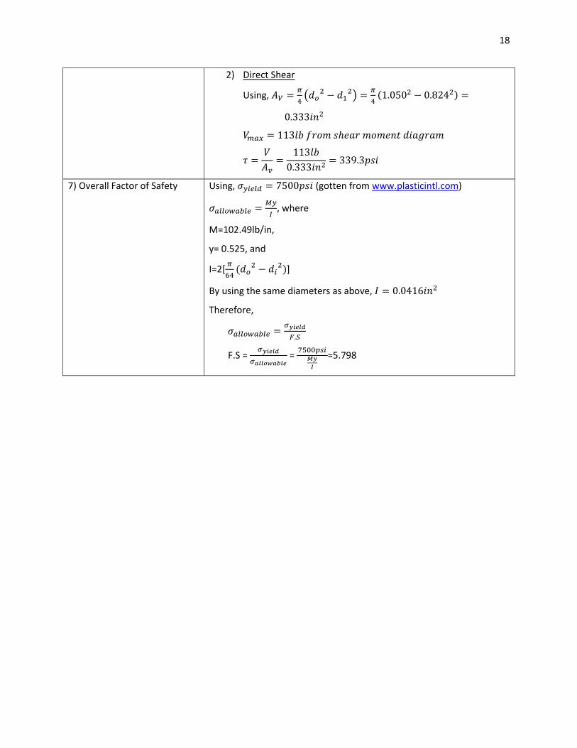
2) Direct Shear
Using,
(
)
( )
7) Overall Factor of Safety Using, (gotten from www.plasticintl.com)
, where
M=102.49lb/in,
y= 0.525, and
I=2[
(
)]
By using the same diameters as above,
Therefore,
F.S =
=
=5.798
19
Appendix B:

20

21

22

23
24
25