ce367g geometric design lab - university of texas at austin · ce367g geometric design lab...
TRANSCRIPT

CE367G Geometric Design Lab
Computer-Aided Design for Roadway Alignments
This homework consists of 4 computer-based assignments, performed in MicroStation (a common CAD
package). Students should perform the labs in ECJ’s 2nd floor lab classroom (ECJ 2.218), printing out
the final results of each lab to turn in on 2/23/17 at the beginning of class.
NOTE: Please be careful to complete all steps in Lab 1, being sure to explore all MicroStation tools and
menus available in Lab 1, since this will save precious time (and avoid serious headaches) in subsequent
Labs.
Before you begin, please be sure to view the short videos for each lab, developed by Dr. Thomas Rioux
for a general overview of each lab’s contents. (Those video links are found before the lab links, at the
above URL.)
After lab access
To access MicroStation from home or computers other than the one in the labs assigned for the course,
Virtual Desktop can be accessed.
i) http://www.engr.utexas.edu/itg/facilities/virtualdesktop
ii) https://wikis.utexas.edu/display/engritgpublic/Connecting+to+the+University+of+Texas+VPN
iii) https://appd.engr.utexas.edu/appdportal
The virtual desktop lets you access a major array of resources online, courtesy of the Cockrell
Engineering School. The first website above gives you all the information required to set up a Virtual
Desktop account. Some nuances about setting up a Virtual Private Network (VPN) is addressed in the
second website. Once everything is setup, the third website can be used in your browser, with the
software it prescribes, to connect to the Virtual Desktop.
Alternatively, MicroStation on can be installed on your personal computer/laptop. To do this, follow the
instructions at this link,
http://www.ce.utexas.edu/prof/kockelman/ce367_201101/MicroStationAccessFromHomePC.pdf

CE367G Geometric Design Lab - Lab 01
Introduction to MicroStation
Objective: Learn the basics of MicroStation required to operate GEOPAK.
Activity: Learn the basics of MicroStation by downloading 2D seed file and level library. Define
settings.
Background: MicroStation is a Computer Aided Drafting (CAD) software package. GEOPAK is an
MDL application that runs on MicroStation. Some knowledge of MicroStation is required to operate
GEOPAK.
Prerequisites: You must have an " Austin" domain computer account. If you do not have an
"Austin" domain computer account, please see the instructor. To activate your " Austin" domain
computer account, please go to http://www.caee.utexas.edu/itss/useraccounts-lrc-students.cfm and
follow the instructions.
In MicroStation, the Left Button on the 3-button mouse is called the Data Button, the Middle Button
(wheel) is called the Tentative Button, and the Right Button is called the Reset Button.
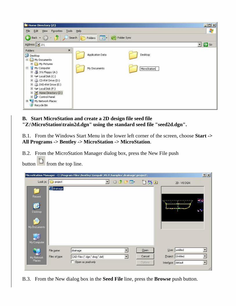
A. Start Windows Explorer and create a MicroStation folder Z:\ MicroStation.
A.1. From the Windows Start Menu in the lower left corner of the screen, choose Start -> All
Programs -> Accessories -> Windows Explorer.
A.2. From the My Documents dialog box, expand "My Computer" and if "Home Directory ( Z:)" is
not listed then contact the instructor.
A.3. From the My Documents dialog box, select "Home Directory ( Z:)".
A.4. From the My Documents dialog box, choose File -> New -> Folder and replace "New Folder"
with " MicroStation".
B. Start MicroStation and create a 2D design file seed file
"Z:\MicroStation\train2d.dgn" using the standard seed file "seed2d.dgn".
B.1. From the Windows Start Menu in the lower left corner of the screen, choose Start ->
All Programs -> Bentley -> MicroStation -> MicroStation.
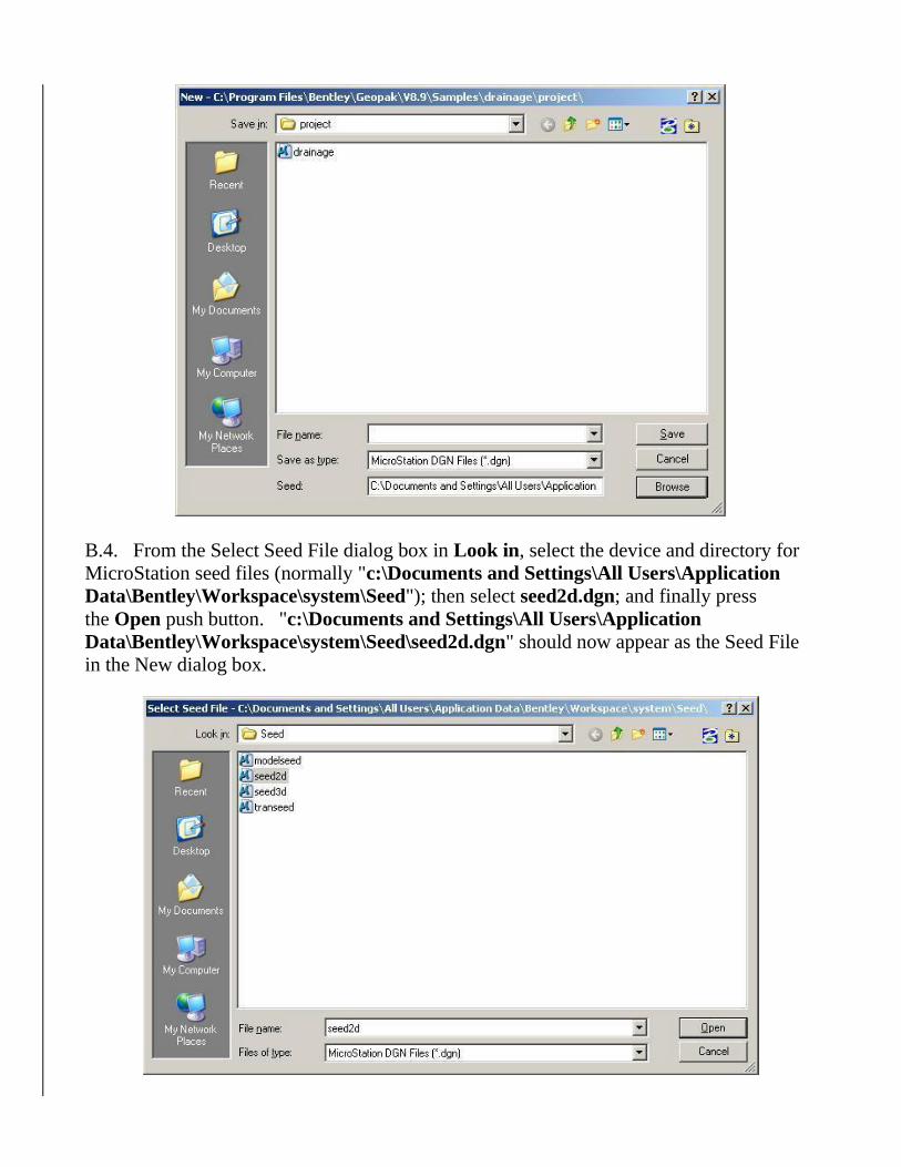
B.2. From the MicroStation Manager dialog box, press the New File push
button from the top line.
B.3. From the New dialog box in the Seed File line, press the Browse push button.
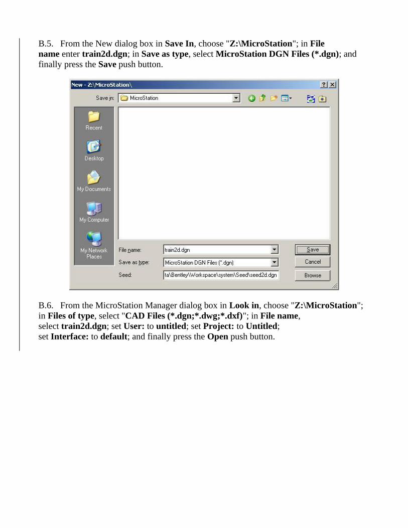
B.4. From the Select Seed File dialog box in Look in, select the device and directory for
MicroStation seed files (normally "c:\Documents and Settings\All Users\Application
Data\Bentley\Workspace\system\Seed"); then select seed2d.dgn; and finally press
the Open push button. "c:\Documents and Settings\All Users\Application
Data\Bentley\Workspace\system\Seed\seed2d.dgn" should now appear as the Seed File
in the New dialog box.
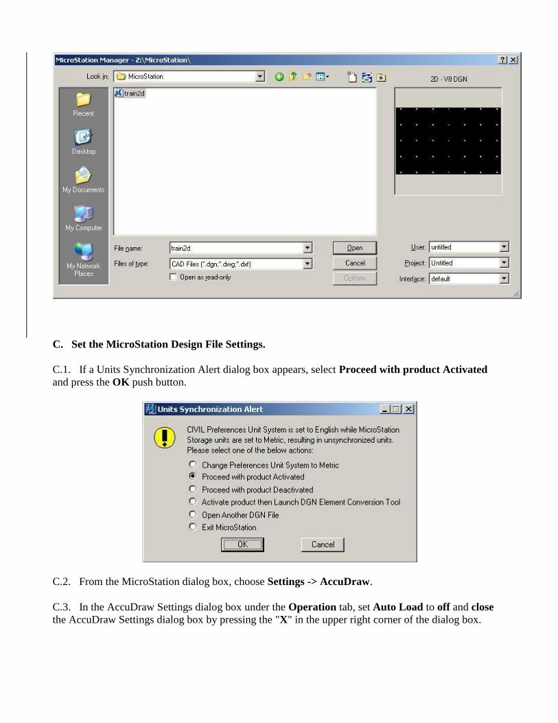
B.5. From the New dialog box in Save In, choose "Z:\MicroStation"; in File
name enter train2d.dgn; in Save as type, select MicroStation DGN Files (*.dgn); and
finally press the Save push button.
B.6. From the MicroStation Manager dialog box in Look in, choose "Z:\MicroStation";
in Files of type, select "CAD Files (*.dgn;*.dwg;*.dxf)"; in File name,
select train2d.dgn; set User: to untitled; set Project: to Untitled;
set Interface: to default; and finally press the Open push button.
C. Set the MicroStation Design File Settings.
C.1. If a Units Synchronization Alert dialog box appears, select Proceed with product Activated
and press the OK push button.
C.2. From the MicroStation dialog box, choose Settings -> AccuDraw.
C.3. In the AccuDraw Settings dialog box under the Operation tab, set Auto Load to off and close
the AccuDraw Settings dialog box by pressing the "X" in the upper right corner of the dialog box.
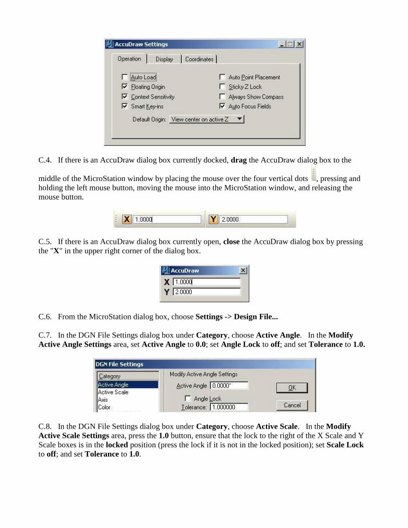
C.4. If there is an AccuDraw dialog box currently docked, drag the AccuDraw dialog box to the
middle of the MicroStation window by placing the mouse over the four vertical dots , pressing and
holding the left mouse button, moving the mouse into the MicroStation window, and releasing the
mouse button.
C.5. If there is an AccuDraw dialog box currently open, close the AccuDraw dialog box by pressing
the "X" in the upper right corner of the dialog box.
C.6. From the MicroStation dialog box, choose Settings -> Design File...
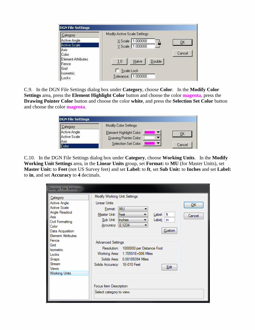
C.7. In the DGN File Settings dialog box under Category, choose Active Angle. In the Modify
Active Angle Settings area, set Active Angle to 0.0; set Angle Lock to off; and set Tolerance to 1.0.
C.8. In the DGN File Settings dialog box under Category, choose Active Scale. In the Modify
Active Scale Settings area, press the 1.0 button, ensure that the lock to the right of the X Scale and Y
Scale boxes is in the locked position (press the lock if it is not in the locked position); set Scale Lock
to off; and set Tolerance to 1.0.
C.9. In the DGN File Settings dialog box under Category, choose Color. In the Modify Color
Settings area, press the Element Highlight Color button and choose the color magenta, press the
Drawing Pointer Color button and choose the color white, and press the Selection Set Color button
and choose the color magenta.
C.10. In the DGN File Settings dialog box under Category, choose Working Units. In the Modify
Working Unit Settings area, in the Linear Units group, set Format: to MU (for Master Units), set
Master Unit: to Feet (not US Survey feet) and set Label: to ft, set Sub Unit: to Inches and set Label:
to in, and set Accuracy to 4 decimals.
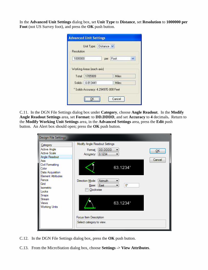
In the Advanced Unit Settings dialog box, set Unit Type to Distance, set Resolution to 1000000 per
Foot (not US Survey foot), and press the OK push button.
C.11. In the DGN File Settings dialog box under Category, choose Angle Readout. In the Modify
Angle Readout Settings area, set Format: to DD.DDDD, and set Accuracy to 4 decimals. Return to
the Modify Working Unit Settings area, in the Advanced Settings area, press the Edit push
button. An Alert box should open; press the OK push button.
C.12. In the DGN File Settings dialog box, press the OK push button.
C.13. From the MicroStation dialog box, choose Settings -> View Attributes.
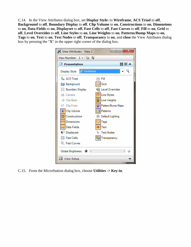
C.14. In the View Attributes dialog box, set Display Style: to Wireframe, ACS Triad to off,
Background to off, Boundary Display to off, Clip Volume to on, Constructions to on, Dimensions
to on, Data Fields to on, Displayset to off, Fast Cells to off, Fast Curves to off, Fill to on, Grid to
off, Level Overrides to off, Line Styles to on, Line Weights to on, Patterns/Bump Maps to on,
Tags to on, Text to on, Text Nodes to off, Transparancy to on, and close the View Attributes dialog
box by pressing the "X" in the upper right corner of the dialog box.
C.15. From the MicroStation dialog box, choose Utilities -> Key-in.
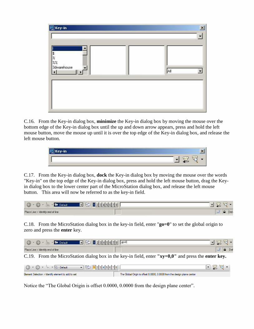
C.16. From the Key-in dialog box, minimize the Key-in dialog box by moving the mouse over the
bottom edge of the Key-in dialog box until the up and down arrow appears, press and hold the left
mouse button, move the mouse up until it is over the top edge of the Key-in dialog box, and release the
left mouse button.
C.17. From the Key-in dialog box, dock the Key-in dialog box by moving the mouse over the words
"Key-in" on the top edge of the Key-in dialog box, press and hold the left mouse button, drag the Key-
in dialog box to the lower center part of the MicroStation dialog box, and release the left mouse
button. This area will now be referred to as the key-in field.
C.18. From the MicroStation dialog box in the key-in field, enter "go=0" to set the global origin to
zero and press the enter key.
C.19. From the MicroStation dialog box in the key-in field, enter "xy=0,0" and press the enter key.
Notice the “The Global Origin is offset 0.0000, 0.0000 from the design plane center”.
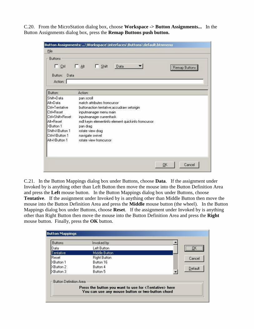
C.20. From the MicroStation dialog box, choose Workspace -> Button Assignments... In the
Button Assignments dialog box, press the Remap Buttons push button.
C.21. In the Button Mappings dialog box under Buttons, choose Data. If the assignment under
Invoked by is anything other than Left Button then move the mouse into the Button Definition Area
and press the Left mouse button. In the Button Mappings dialog box under Buttons, choose
Tentative. If the assignment under Invoked by is anything other than Middle Button then move the
mouse into the Button Definition Area and press the Middle mouse button (the wheel). In the Button
Mappings dialog box under Buttons, choose Reset. If the assignment under Invoked by is anything
other than Right Button then move the mouse into the Button Definition Area and press the Right
mouse button. Finally, press the OK button.
C.22. In the Button Assignments dialog box, press the OK button.
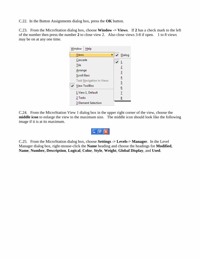
C.23. From the MicroStation dialog box, choose Window -> Views. If 2 has a check mark to the left
of the number then press the number 2 to close view 2. Also close views 3-8 if open. 1 to 8 views
may be on at any one time.
C.24. From the MicroStation View 1 dialog box in the upper right corner of the view, choose the
middle icon to enlarge the view to the maximum size. The middle icon should look like the following
image if it is at its maximum.
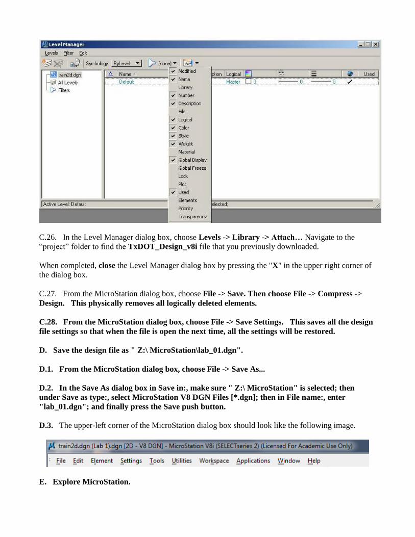
C.25. From the MicroStation dialog box, choose Settings -> Levels-> Manager. In the Level
Manager dialog box, right-mouse-click the Name heading and choose the headings for Modified,
Name, Number, Description, Logical, Color, Style, Weight, Global Display, and Used.
C.26. In the Level Manager dialog box, choose Levels -> Library -> Attach… Navigate to the
“project” folder to find the TxDOT_Design_v8i file that you previously downloaded.
When completed, close the Level Manager dialog box by pressing the "X" in the upper right corner of
the dialog box.
C.27. From the MicroStation dialog box, choose File -> Save. Then choose File -> Compress ->
Design. This physically removes all logically deleted elements.
C.28. From the MicroStation dialog box, choose File -> Save Settings. This saves all the design
file settings so that when the file is open the next time, all the settings will be restored.
D. Save the design file as " Z:\ MicroStation\lab_01.dgn".
D.1. From the MicroStation dialog box, choose File -> Save As...
D.2. In the Save As dialog box in Save in:, make sure " Z:\ MicroStation" is selected; then
under Save as type:, select MicroStation V8 DGN Files [*.dgn]; then in File name:, enter
"lab_01.dgn"; and finally press the Save push button.
D.3. The upper-left corner of the MicroStation dialog box should look like the following image.
E. Explore MicroStation.
E.1. The top of the MicroStation window has "File", "Edit", "Element", "Settings", "Tools",
"Utilities", "Workspace", "Applications", "Window", and "Help" menus that provide the normal
Windows functionality. See the above image. On some systems, "Applications" may not be
displayed; please contact the instructor if this is the case.
E.2. The File menu contains the MicroStation specific items "Compress Design", "Save Settings",
"Reference", "Print", "Exit", and others. Take this opportunity to look at the menus under File. Each
time the user adds, deletes, or modifies an element with MicroStation, the change is immediately
written to the design file.
E.2.a. File -> Compress -> Design is used to permanently delete MicroStation elements (amongst
other things) that have been marked for deletion by the user from the current design file.
E.2.b. File -> Save Settings saves the current MicroStation settings in the current design file so that
when the file is entered again, the same views, levels, etc. are restored.
E.2.c. File -> References allows the user to attach, detach, and manipulate reference files. Up to
256 reference files may be attached to a single design file for read-only access to the data. The
reference files may be the current MicroStation design file, other MicroStation design files, or raster
files. Each reference file may be displayed or not displayed and the levels to be displayed may be
specified for each design reference file.
E.2.d. File -> Print allows the user to generate hard copy output of the design file.
E.2.e. File -> Exit terminates your MicroStation session.
E.3. The Edit menu contains the MicroStation specific items "Undo", "Redo", and numerous
others. Take this opportunity to look at the menus under Edit.
E.3.a. Edit -> Undo allows the user to undo the last MicroStation command. [Ctrl + Z]
E.3.b. Edit -> Redo negates the last undo operation. [Ctrl + R}
E.4. The Element menu contains the MicroStation specific items "Cells", "Dimension Styles",
and several others. Take this opportunity to look at the menus under Element.
E.4.a. The Element -> Cells menu allows the user to attach and detach cell libraries (a file containing
a collection of cells) and to select a cell for placement from among the cells in a cell library. A cell is
a collection of one or more MicroStation elements that may be placed, manipulated, and deleted as one
item. You may have only one cell library attached at any one time. Once a cell is placed, you no
longer need the cell library attached because the cell is copied to the current design file. When shared
cells are used, the definition of the cell is added to the design file only once at a location of (0,0), a
scale of 1.0, and a rotation of 0.0 degrees and all other placements refer to the shared cell definition
with specific location, scale, and rotation information. Shared cells thus use less disk space than
normal cells. When normal cells are used, the cell is copied to the design file with specific location,
scale, and rotation information applied when the copy is made.
E.4.b. The Element -> Dimension Styles menu provides for the selection of numerous attributed for
dimensioning.
E.5. The Settings menu contains the MicroStation specific items "Design File...", "Levels",
"Locks", "Snaps", "View Attributes", and several others. Take this opportunity to look at the
menus under Settings.
E.5.a. The Settings -> Design File... menu allows the user to set or change many categories of
items. We have used the Design File menu in section C above to set the Active Angle, Active Scale,
Element Highlight Color, Drawing Pointer Color, Selection Set Color, Coordinate Readout, and
Working Units.
E.5.b. The Settings -> Level menus allows the user to add and modify levels, to control which levels
are displayed and hidden for each view (1-8 views may be on at any one time), and to control the
active level (the level where all new user elements are placed). Level segregates the data by allowing
the user to view or not view the data on individual levels. View levels can be applied to the single
selected view, to multiple views, or to all views. The active level is indicated by the green color, the
displayed level(s) are indicated by a blue background, and hidden level(s) are indicated by white
backgrounds. The active level applies to all views. GEOPAK controls the level of each element
placed by GEOPAK through the Design and Computation Manager. An organization can describe to
GEOPAK the color, level, weight, and style for each GEOPAK object.
E.5.c. The Settings -> Levels -> Manager menu allows the user to add and modify levels. Each
level has a user-defined name, an assigned level number, an optional description, and other
characteristics.
E.5.d. The Settings -> Levels -> Display menu allows the user to control which levels are displayed
and hidden for each view and to control the active level. View levels can be applied to the single
selected view, to multiple views, or to all views. The active level is indicated by the green color, the
displayed level(s) are indicated by a blue background, and hidden level(s) are indicated by white
backgrounds.
E.5.e. The Settings -> Locks menu contains "Full", "Toggles", "Axis", "Grid", "Unit", "Association",
"Level", "Graphic Group", "Text Node", "Isometric", "Annotation Scale", and "ACS Plane". Toggles
opens a dialog box to set "Axis Lock", "Grid Lock", "Unit Lock", "Snap Lock", "Association Lock",
"Level Lock", "Graphic Group", "Text Node Lock", "Isometric Lock", "Annotation Scale", and "ACS
Plane". Full allows the user to specify additional parameters for some locks. Toggles allows the user
to define whether the lock is active or not active. The locks controls how MicroStation uses tentative
and data point buttons.
E.5.f. The Settings -> Snaps menu contains "Button Bar", "AccuSnap", "Multi-snaps", and a number
of “snap” options. Snapping allows the user to pick a point along an existing element. The Button Bar
creates a Snap Mode tool box which can be moved around the window or docked along any
edge. The AccuSnap opens the AccuSnap Settings dialog box. The individual snap options are:
The Near Point Snap uses the closest point to the cursor along the element
The Midpoint Snap uses the midpoints of elements and segments of elements;
The Center Snap uses the centers and centroids of elements;
The Origin Snap uses the origins of cells;
The Bisector Snap uses the midpoints of entire elements;
Intersection Snap - intersect another element with the point of intersection at its starting or
ending point;
Tangent Snap - be tangent to another element;
Tangent Point Snap - be tangent to another element with the point of tangency at its starting or
ending point;
Perpendicular Snap - be perpendicular to another element;
Perpendicular Point Snap - be perpendicular to another element with the point of intersection at
its starting or ending point;
Parallel Snap - be parallel to another element;
Point Through Snap - pass through a particular point on the design plane; and
Point On Snap - start or end on another element.
E.5.g. The Settings -> View Attributes menu allows the user to control the viewing options for many
items such as whether Construction elements are displayed or hidden, whether Fill is active or inactive
(shapes are filled), whether the Grid is displayed or hidden, whether Line Styles are displayed, whether
Line Weights are displayed, or whether Text is displayed. View Attributes can be applied to the
single selected View Number or to all views.
E.6. The Tools menu contains the MicroStation specific items "Attributes", "Primary",
"Standard", "Main", "Task Navigation", and numerous other tools. Take this opportunity to
look at the menus under Tools.
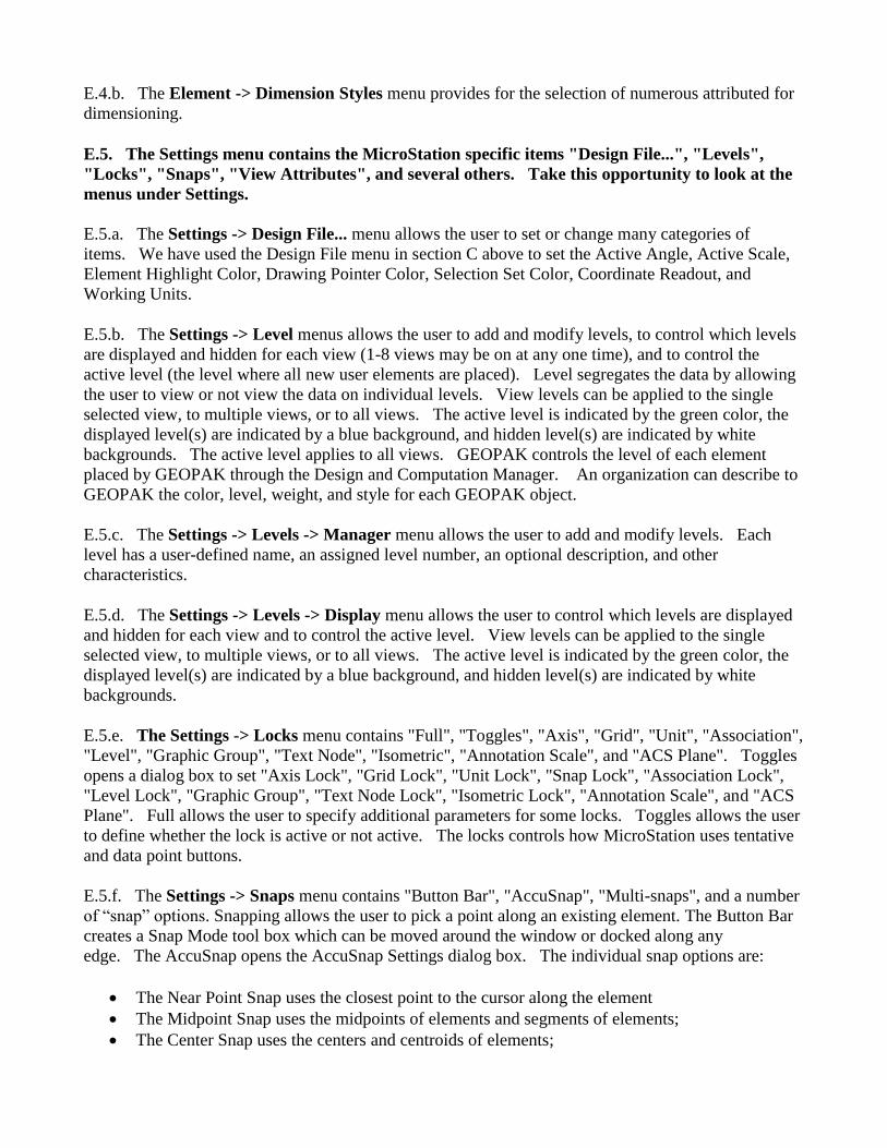
E.6.a. If Tools -> Attributes does not have a check mark to its left then choose Attributes. The
Attributes menu will appear. If the Attributes menu appears as below then dock the Attributes menu
by moving the mouse over the words "Attributes" on the top edge of the Attributes menu, press and
hold the left mouse button, drag the Attributes menu to the top of the MicroStation window to the
leftmost position under File, and finally release the left mouse button. This action will dock the
Attributes menu. The Attributes menu contains items for Active Level (Level 1 in the picture below),
Active Color (2 in the picture below), Active Line Style (3 in the picture below), Active Line Weight
(thickness) (4 in the picture below), and a visualization of the line using the active color, style, and
weight. Each MicroStation element may have specific values of each of these attributes based upon
the current settings when the element is added to the design file. There are tools to allow the user to
change any of the attribute values. MicroStation applications like GEOPAK may set the level, color,
style, weight, and class of an element as they add an element to the design file without affecting the
current settings.
E.6.a.1. Active Level specifies one level or drawing plane. Level segregates the data allowing the
user to view or not view the data. Individual levels may be viewed or hidden at any time.
E.6.a.2. Active Color specifies one of 255 colors (0-254) from an active Color Table. The value in
the Color Table specifies a 24-bit true-color value (16,777,216 color combinations) to be associated
with the Active Color.
E.6.a.3. Active Line Style specifies one of 8 predefined numeric styles (0-7), one of 25 predefined
named styles (Border to Wide Dash), or one of a virtually unlimited number of Custom styles. Line
Style defines the appearance of data (solid, dashed, dotted, etc.). The user may create his/her own
Custom styles (Element -> Line Style -> Custom).
E.6.a.4. Active Weight specifies one of 16 predefined weights (0-15). Weight defines the thickness
or number of pixels displayed on the screen for graphics. When plotting the design file, the Weight
can be converted to a line thickness.
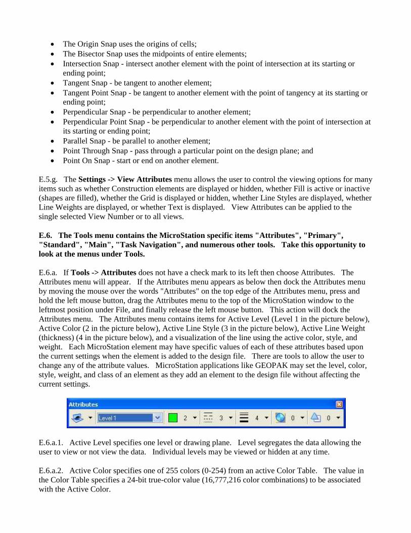
E.6.b. If Tools -> Primary does not have a check mark to its left then choose Primary. The Primary
Tools menu will appear. If the Primary Tools menu appears as below then dock the Primary Tools
menu by moving the mouse over the words "Primary Tools" on the top edge of the Primary Tools
menu, press and hold the left mouse button, drag the Primary Tools menu to the top of the
MicroStation window to the left of the Attributes menu, and finally release the left mouse
button. This action will dock the Primary Tools menu. The Primary Tools menu contains, from left
to right, items for Models, References (same as File -> Reference), Raster Manager, Point Clouds,
Saved Views, Level Manager (same as Settings -> Levels -> Manager), Level Display (same as
Settings -> Levels -> Display), Cells, Auxiliary Coordinates, Element Information; Toggle
AccuDraw, and Pop Set Enable/Disable.
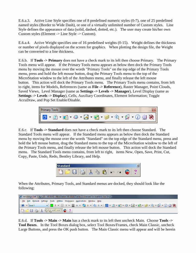
E.6.c. If Tools -> Standard does not have a check mark to its left then choose Standard. The
Standard Tools menu will appear. If the Standard menu appears as below then dock the Standard
menu by moving the mouse over the words "Standard" on the top edge of the Standard menu, press and
hold the left mouse button, drag the Standard menu to the top of the MicroStation window to the left of
the Primary Tools menu, and finally release the left mouse button. This action will dock the Standard
menu. The Standard Tools menu contains, from left to right, items New, Open, Save, Print, Cut,
Copy, Paste, Undo, Redo, Bentley Library, and Help.
When the Attributes, Primary Tools, and Standard menus are docked, they should look like the
following:
E.6.d. If Tools -> Main -> Main has a check mark to its left then uncheck Main. Choose Tools ->
Tool Boxes. In the Tool Boxes dialog box, select Tool Boxes/Frames, check Main Classic, uncheck
Large Buttons, and press the OK push button. The Main Classic menu will appear and will be herein
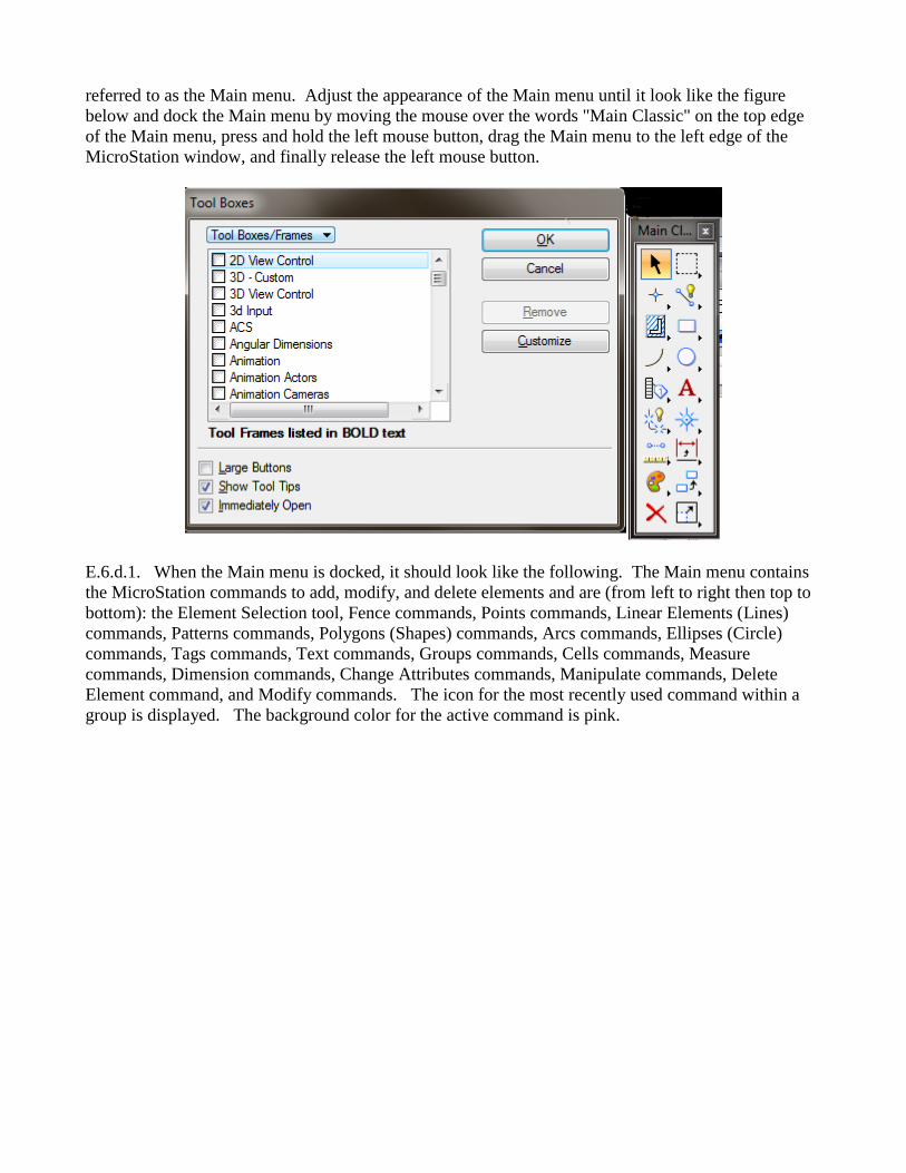
referred to as the Main menu. Adjust the appearance of the Main menu until it look like the figure
below and dock the Main menu by moving the mouse over the words "Main Classic" on the top edge
of the Main menu, press and hold the left mouse button, drag the Main menu to the left edge of the
MicroStation window, and finally release the left mouse button.
E.6.d.1. When the Main menu is docked, it should look like the following. The Main menu contains
the MicroStation commands to add, modify, and delete elements and are (from left to right then top to
bottom): the Element Selection tool, Fence commands, Points commands, Linear Elements (Lines)
commands, Patterns commands, Polygons (Shapes) commands, Arcs commands, Ellipses (Circle)
commands, Tags commands, Text commands, Groups commands, Cells commands, Measure
commands, Dimension commands, Change Attributes commands, Manipulate commands, Delete
Element command, and Modify commands. The icon for the most recently used command within a
group is displayed. The background color for the active command is pink.
E.6.d.2. All the Main menu commands except the Element Selection and the Delete Element
commands can be expanded to show all available commands in the group by moving the mouse over
the Main menu command, press and hold the left mouse button, move the mouse horizontally then
vertically over the desired command, and finally release the left mouse button. The name of the
command will appear in the message box at the bottom of the MicroStation window after the command
has been chosen.
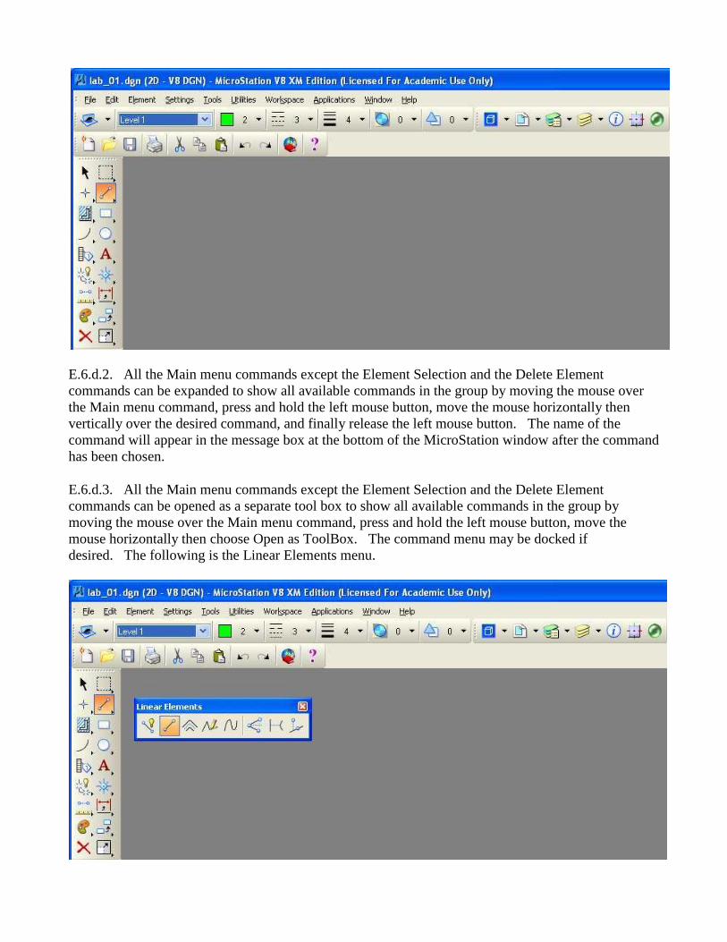
E.6.d.3. All the Main menu commands except the Element Selection and the Delete Element
commands can be opened as a separate tool box to show all available commands in the group by
moving the mouse over the Main menu command, press and hold the left mouse button, move the
mouse horizontally then choose Open as ToolBox. The command menu may be docked if
desired. The following is the Linear Elements menu.

E.7. The Utilities menu contains the MicroStation specific items "Key-in", "MDL
Applications", and several others. Take this opportunity to look at the menus under Utilities.
E.7.a. The Utilities -> Key-in dialog box allows the user to enter a MicroStation command, to select
a MicroStation command from the hierarchical list of commands, or to select a MicroStation command
from the list of recent key-in commands. In the key-in field, you may enter up-arrow and down-arrow
keys for command recall and selection and enter the home, end, delete, backspace, left-arrow, and
right-arrow keys for command editing. To paste text into the key-in field from the Windows paste
buffer, move the cursor to the key-in field, press and hold the shift key, and press the insert key.
E.7.b. The Utilities -> MDL Applications dialog box allows the user to load (start), unload (stop),
and get additional information about MDL Applications. GEOPAK is an MDL Application.
E.8. The Workspace menu contains the MicroStation specific items "Configuration...", "Button
Assignments...", and several other items. Take this opportunity to look at the menus under
Workspace.
E.8.a. The Configuration dialog box allows the user to specify many MicroStation parameters. Many
of these configuration variables are set when you start MicroStation.
E.8.b. The Button Assignments dialog box allows the user to specify the association between the
buttons on the mouse and the meaning to MicroStation. The Data button specifies a coordinate to
MicroStation (or if the Tentative button was last used then accepts the snapped, calculated coordinate)
and is normally the left button on the mouse. The Tentative button specifies a coordinate to
MicroStation that causes MicroStation to search the design file for an element close to the coordinate
specified, calculate a coordinate based upon the current snap feature, move an enlarged cursor to the
calculated coordinate, and highlight the selected element. If the snapped, calculated coordinate is not
acceptable, the user may enter additional Tentative buttons until an acceptable coordinate is
displayed. To accept the Tentative button snapped, calculated coordinate, the user would enter a
single Data button (the location of the cursor for the Data button is not pertinent). The Tentative
button is normally the center button on a three-button mouse, the wheel button on a two-button mouse
with a wheel, or a left button - right button chord (left and right button pressed at the same time) on a
two-button mouse. The Reset button specifies a reset or reject action to MicroStation and is normally
the right button on the mouse. The definition of the Command button is not important because
MicroStation interprets any button on a dialog box to be a Command button. If the buttons are not
assigned the way that you want them, select a button from the list and in the Button Definition Area,
press the mouse button or combination of Alt keys and mouse buttons that you want. When
completed, press the OK push button.
E.9. The Applications menu contains menus added by MicroStation MDL Applications and MBE
Applications. On some systems, "Applications" may not be displayed. GEOPAK ROAD may be
listed on the Applications menu. Take this opportunity to look at the menus under Applications.
E.10. The Window menu contains the MicroStation specific items "Views" and several others. Take
this opportunity to look at the menus under Window. MicroStation can have up to 8 windows or
views open simultaneously. Each window or view has its own size (height and width), location within
the MicroStation window, levels to display or hide (Settings -> Levels -> Display), view attributes
(Settings -> View Attributes), panning, zooming, rotation, and orientation (for 3D files: top, bottom,
left, orthogonal, etc.). Choose Window -> Views; if 1 (for view 1) does not have a check mark to its
left then select 1 (view 1 will be Opened) and if any of 2 through 8 has a check mark to its left then
select each one (the view will be Closed).
E.11. The Help menu contains the MicroStation specific items to assist the user in using and finding
online information about MicroStation. Take this opportunity to look at the menus under Help.
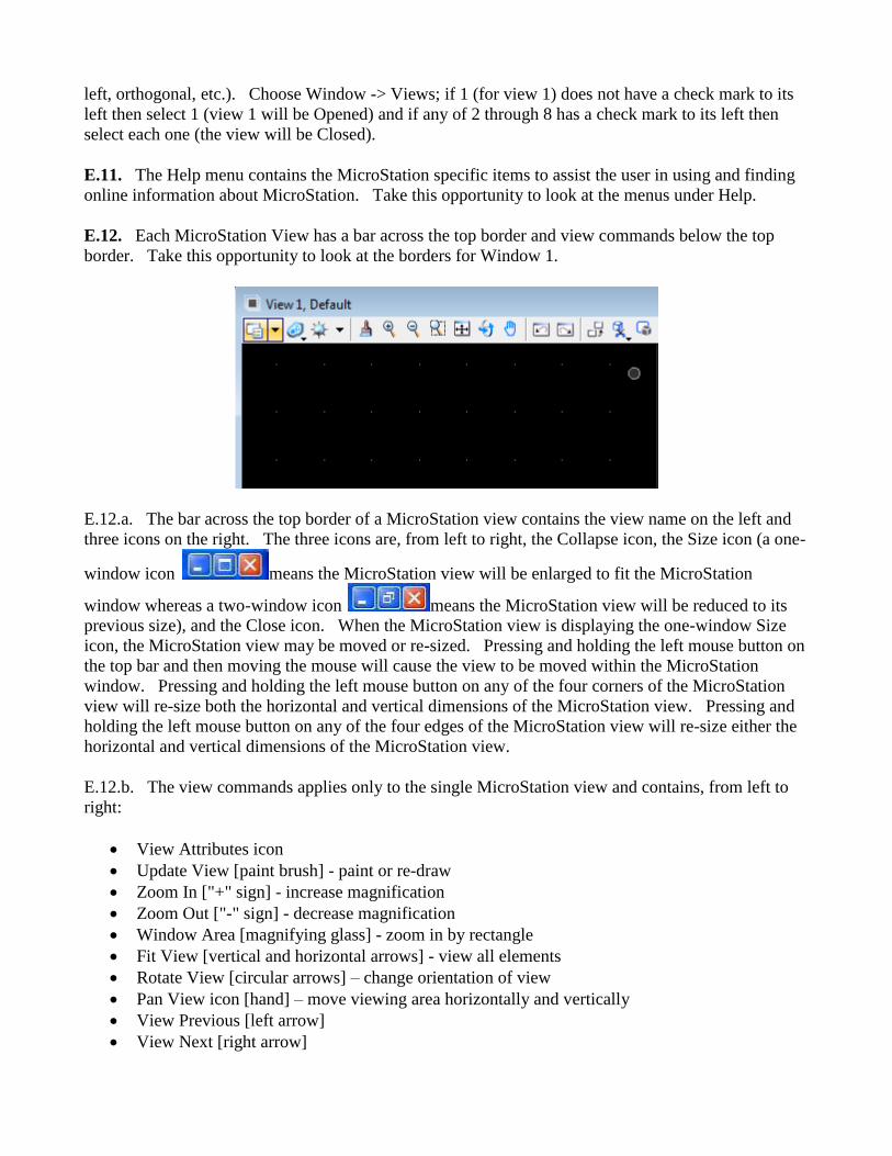
E.12. Each MicroStation View has a bar across the top border and view commands below the top
border. Take this opportunity to look at the borders for Window 1.
E.12.a. The bar across the top border of a MicroStation view contains the view name on the left and
three icons on the right. The three icons are, from left to right, the Collapse icon, the Size icon (a one-
window icon means the MicroStation view will be enlarged to fit the MicroStation
window whereas a two-window icon means the MicroStation view will be reduced to its
previous size), and the Close icon. When the MicroStation view is displaying the one-window Size
icon, the MicroStation view may be moved or re-sized. Pressing and holding the left mouse button on
the top bar and then moving the mouse will cause the view to be moved within the MicroStation
window. Pressing and holding the left mouse button on any of the four corners of the MicroStation
view will re-size both the horizontal and vertical dimensions of the MicroStation view. Pressing and
holding the left mouse button on any of the four edges of the MicroStation view will re-size either the
horizontal and vertical dimensions of the MicroStation view.
E.12.b. The view commands applies only to the single MicroStation view and contains, from left to
right:
View Attributes icon
Update View [paint brush] - paint or re-draw
Zoom In ["+" sign] - increase magnification
Zoom Out ["-" sign] - decrease magnification
Window Area [magnifying glass] - zoom in by rectangle
Fit View [vertical and horizontal arrows] - view all elements
Rotate View [circular arrows] – change orientation of view
Pan View icon [hand] – move viewing area horizontally and vertically
View Previous [left arrow]
View Next [right arrow]
Copy View
Clip Volume
Clip Mask
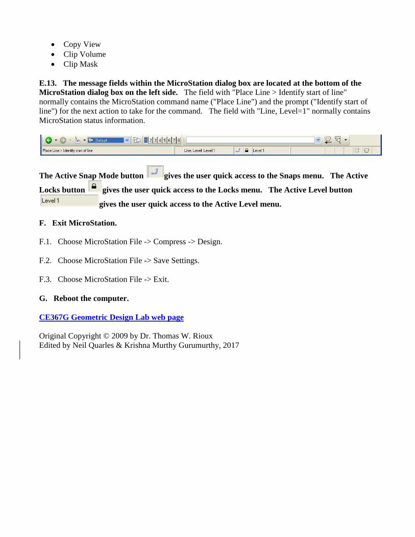
E.13. The message fields within the MicroStation dialog box are located at the bottom of the
MicroStation dialog box on the left side. The field with "Place Line > Identify start of line"
normally contains the MicroStation command name ("Place Line") and the prompt ("Identify start of
line") for the next action to take for the command. The field with "Line, Level=1" normally contains
MicroStation status information.
The Active Snap Mode button gives the user quick access to the Snaps menu. The Active
Locks button gives the user quick access to the Locks menu. The Active Level button
gives the user quick access to the Active Level menu.
F. Exit MicroStation.
F.1. Choose MicroStation File -> Compress -> Design.
F.2. Choose MicroStation File -> Save Settings.
F.3. Choose MicroStation File -> Exit.
G. Reboot the computer.
CE367G Geometric Design Lab web page
Original Copyright © 2009 by Dr. Thomas W. Rioux
Edited by Neil Quarles & Krishna Murthy Gurumurthy, 2017
CE 367G Geometric Design Lab- Lab 02
Leg Centerline and Lanes using MicroStation
Objective: Learn the basics of MicroStation required to operate GEOPAK by drawing a simple leg
centerline and lanes.
Activity: Start MicroStation and create a 2D design file " Z:\ MicroStation\lab_02.dgn" using the
seed file " Z:\ MicroStation\train2d.dgn" ; Use MicroStation to Draw a Leg Centerline; Use
MicroStation to copy the centerline 12 feet parallel both above and below the centerline for lane edges;
Change the lane edge attributes to color green (color=2) and solid style (style=0); Place a landscape
oriented rectangle centered around the roadway in 8.5" by 11" proportion (2070 feet by 1583 feet);
Place the title "Lab Assignment 02" centered at the top and your name, class name, and assignment due
date in the lower right at a text height and width of 75 feet; Compress the MicroStation design file and
Save the MicroStation design file settings; Select the black and white laser printer as the default
printer; Place a fence around the rectangle and print the drawing; Exit MicroStation; and Reboot the
computerReboot the computer.
Background: MicroStation is a Computer Aided Drafting (CAD) software package. GEOPAK is an
MDL application that runs on MicroStation. Some knowledge of MicroStation is required to operate
GEOPAK. Intersection analysis begins by defining the geometry of the intersection. A circular fillet
is an arc of a circle that is tangent to two intersecting lines.
A. Start MicroStation and create a 2D design file " Z:\ MicroStation\lab_02.dgn" using the seed
file " Z:\ MicroStation\train2d.dgn".
B. Use MicroStation to Draw a Leg Centerline.
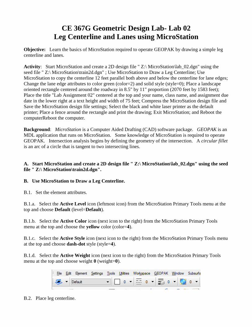
B.1. Set the element attributes.
B.1.a. Select the Active Level icon (leftmost icon) from the MicroStation Primary Tools menu at the
top and choose Default (level=Default).
B.1.b. Select the Active Color icon (next icon to the right) from the MicroStation Primary Tools
menu at the top and choose the yellow color (color=4).
B.1.c. Select the Active Style icon (next icon to the right) from the MicroStation Primary Tools menu
at the top and choose dash-dot style (style=4).
B.1.d. Select the Active Weight icon (next icon to the right) from the MicroStation Primary Tools
menu at the top and choose weight 0 (weight=0).
B.2. Place leg centerline.
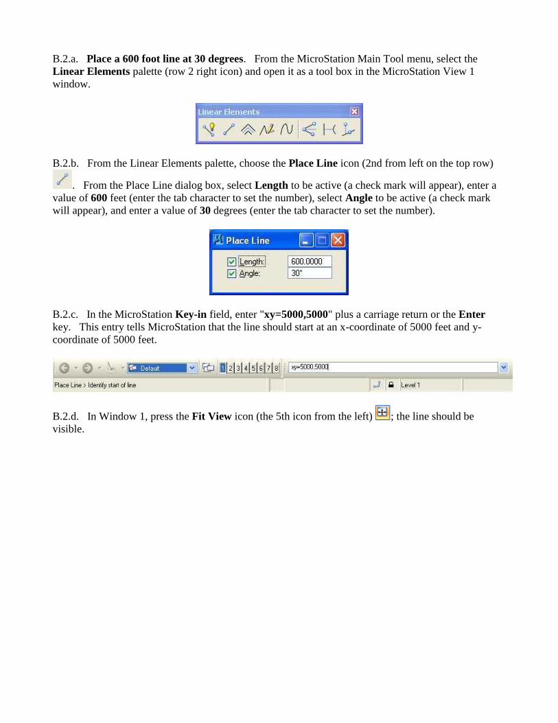
B.2.a. Place a 600 foot line at 30 degrees. From the MicroStation Main Tool menu, select the
Linear Elements palette (row 2 right icon) and open it as a tool box in the MicroStation View 1
window.
B.2.b. From the Linear Elements palette, choose the Place Line icon (2nd from left on the top row)
. From the Place Line dialog box, select Length to be active (a check mark will appear), enter a
value of 600 feet (enter the tab character to set the number), select Angle to be active (a check mark
will appear), and enter a value of 30 degrees (enter the tab character to set the number).
B.2.c. In the MicroStation Key-in field, enter "xy=5000,5000" plus a carriage return or the Enter
key. This entry tells MicroStation that the line should start at an x-coordinate of 5000 feet and y-
coordinate of 5000 feet.
B.2.d. In Window 1, press the Fit View icon (the 5th icon from the left) ; the line should be
visible.
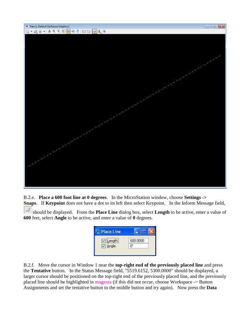
B.2.e. Place a 600 foot line at 0 degrees. In the MicroStation window, choose Settings ->
Snaps. If Keypoint does not have a dot to its left then select Keypoint. In the Inform Message field,
should be displayed. From the Place Line dialog box, select Length to be active, enter a value of
600 feet, select Angle to be active, and enter a value of 0 degrees.
B.2.f. Move the cursor in Window 1 near the top-right end of the previously placed line and press
the Tentative button. In the Status Message field, "5519.6152, 5300.0000" should be displayed, a
larger cursor should be positioned on the top-right end of the previously placed line, and the previously
placed line should be highlighted in magenta (if this did not occur, choose Workspace -> Button
Assignments and set the tentative button to the middle button and try again). Now press the Data
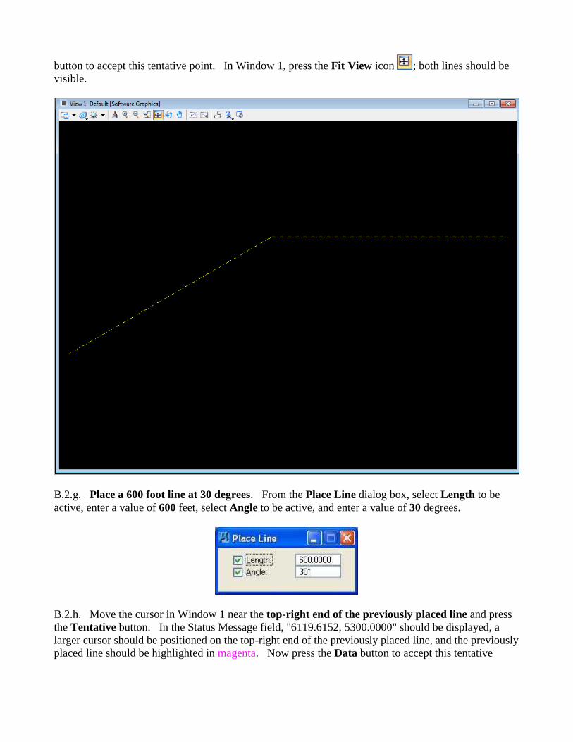
button to accept this tentative point. In Window 1, press the Fit View icon ; both lines should be
visible.
B.2.g. Place a 600 foot line at 30 degrees. From the Place Line dialog box, select Length to be
active, enter a value of 600 feet, select Angle to be active, and enter a value of 30 degrees.
B.2.h. Move the cursor in Window 1 near the top-right end of the previously placed line and press
the Tentative button. In the Status Message field, "6119.6152, 5300.0000" should be displayed, a
larger cursor should be positioned on the top-right end of the previously placed line, and the previously
placed line should be highlighted in magenta. Now press the Data button to accept this tentative
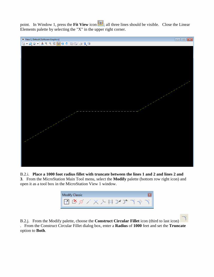
point. In Window 1, press the Fit View icon ; all three lines should be visible. Close the Linear
Elements palette by selecting the "X" in the upper right corner.
B.2.i. Place a 1000 foot radius fillet with truncate between the lines 1 and 2 and lines 2 and
3. From the MicroStation Main Tool menu, select the Modify palette (bottom row right icon) and
open it as a tool box in the MicroStation View 1 window.
B.2.j. From the Modify palette, choose the Construct Circular Fillet icon (third to last icon)
. From the Construct Circular Fillet dialog box, enter a Radius of 1000 feet and set the Truncate
option to Both.
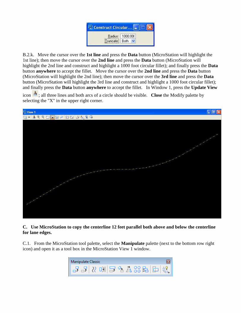
B.2.k. Move the cursor over the 1st line and press the Data button (MicroStation will highlight the
1st line); then move the cursor over the 2nd line and press the Data button (MicroStation will
highlight the 2nd line and construct and highlight a 1000 foot circular fillet); and finally press the Data
button anywhere to accept the fillet. Move the cursor over the 2nd line and press the Data button
(MicroStation will highlight the 2nd line); then move the cursor over the 3rd line and press the Data
button (MicroStation will highlight the 3rd line and construct and highlight a 1000 foot circular fillet);
and finally press the Data button anywhere to accept the fillet. In Window 1, press the Update View
icon ; all three lines and both arcs of a circle should be visible. Close the Modify palette by
selecting the "X" in the upper right corner.
C. Use MicroStation to copy the centerline 12 feet parallel both above and below the centerline
for lane edges.
C.1. From the MicroStation tool palette, select the Manipulate palette (next to the bottom row right
icon) and open it as a tool box in the MicroStation View 1 window.
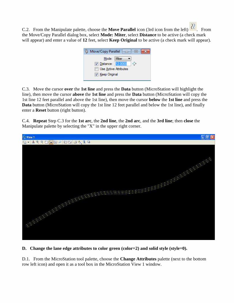
C.2. From the Manipulate palette, choose the Move Parallel icon (3rd icon from the left) . From
the Move/Copy Parallel dialog box, select Mode: Miter, select Distance to be active (a check mark
will appear) and enter a value of 12 feet, select Keep Original to be active (a check mark will appear).
C.3. Move the cursor over the 1st line and press the Data button (MicroStation will highlight the
line), then move the cursor above the 1st line and press the Data button (MicroStation will copy the
1st line 12 feet parallel and above the 1st line), then move the cursor below the 1st line and press the
Data button (MicroStation will copy the 1st line 12 feet parallel and below the 1st line), and finally
enter a Reset button (right button).
C.4. Repeat Step C.3 for the 1st arc, the 2nd line, the 2nd arc, and the 3rd line; then close the
Manipulate palette by selecting the "X" in the upper right corner.
D. Change the lane edge attributes to color green (color=2) and solid style (style=0).
D.1. From the MicroStation tool palette, choose the Change Attributes palette (next to the bottom
row left icon) and open it as a tool box in the MicroStation View 1 window.

D.2. From the Change Attributes palette, choose the Change Element Attributes icon (leftmost
icon) . From the Change Element Attributes dialog box, select Level to be active (a check mark
will appear) and choose Default, select Color to be active (a check mark will appear) and choose the
green color (color=2), select Style to be active (a check mark will appear) and select solid (style=0),
and make sure that Use Active Attributes, Level, Weight, and Class are not active.
D.3. Move the cursor over the 1st line copied parallel 12 feet above and press the Data button
(MicroStation will highlight the line) then move the cursor over the 1st line copied parallel 12 feet
below and press the Data button (MicroStation will change the attributes of the previously selected
line and highlight the newly selected line).
D.4. Repeat Step D.3 for all other arcs and lines except the centerline elements and finally press a
Data button anywhere to accept the last element; then close the Change Attributes palette by selecting
the "X" in the upper right corner.
E. Place a landscape oriented rectangle centered around the roadway in 8.5" by 11" proportion
(2070 feet by 1583 feet).
E.1. From the MicroStation tool palette, choose the Polygons palette (3rd row right icon) and open it
as a tool box in the MicroStation View 1 window.
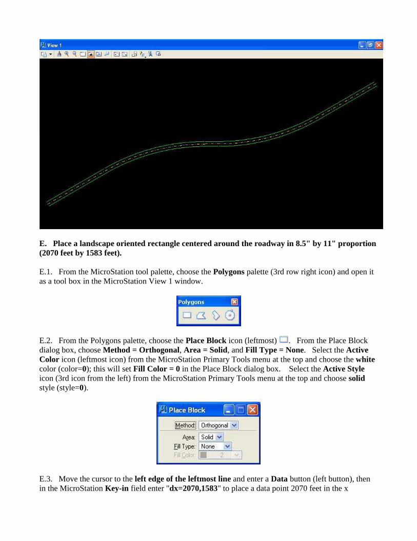
E.2. From the Polygons palette, choose the Place Block icon (leftmost) . From the Place Block
dialog box, choose Method = Orthogonal, Area = Solid, and Fill Type = None. Select the Active
Color icon (leftmost icon) from the MicroStation Primary Tools menu at the top and choose the white
color (color=0); this will set Fill Color = 0 in the Place Block dialog box. Select the Active Style
icon (3rd icon from the left) from the MicroStation Primary Tools menu at the top and choose solid
style (style=0).
E.3. Move the cursor to the left edge of the leftmost line and enter a Data button (left button), then
in the MicroStation Key-in field enter "dx=2070,1583" to place a data point 2070 feet in the x
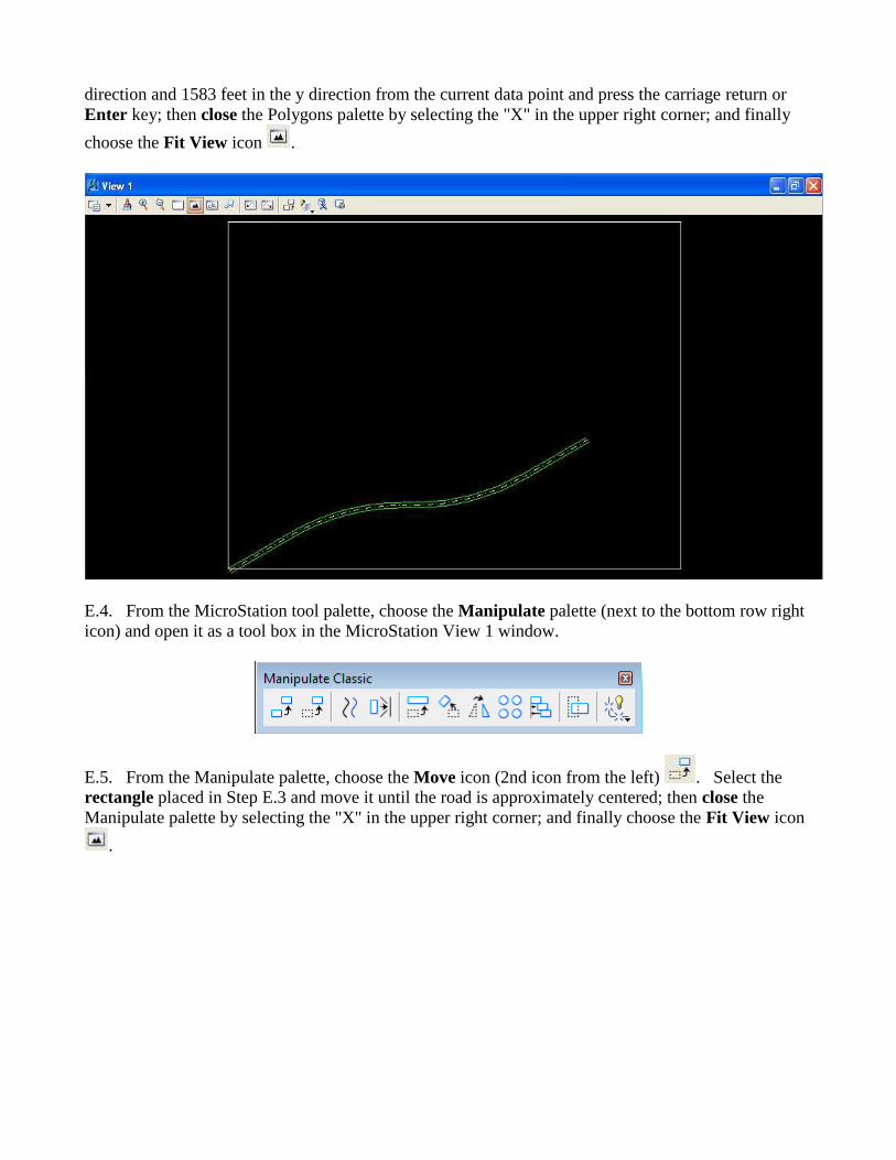
direction and 1583 feet in the y direction from the current data point and press the carriage return or
Enter key; then close the Polygons palette by selecting the "X" in the upper right corner; and finally
choose the Fit View icon .
E.4. From the MicroStation tool palette, choose the Manipulate palette (next to the bottom row right
icon) and open it as a tool box in the MicroStation View 1 window.
E.5. From the Manipulate palette, choose the Move icon (2nd icon from the left) . Select the
rectangle placed in Step E.3 and move it until the road is approximately centered; then close the
Manipulate palette by selecting the "X" in the upper right corner; and finally choose the Fit View icon
.
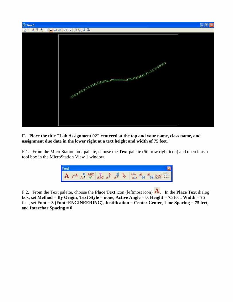
F. Place the title "Lab Assignment 02" centered at the top and your name, class name, and
assignment due date in the lower right at a text height and width of 75 feet.
F.1. From the MicroStation tool palette, choose the Text palette (5th row right icon) and open it as a
tool box in the MicroStation View 1 window.
F.2. From the Text palette, choose the Place Text icon (leftmost icon) . In the Place Text dialog
box, set Method = By Origin, Text Style = none, Active Angle = 0, Height = 75 feet, Width = 75
feet, set Font = 3 (Font=ENGINEERING), Justification = Center Center, Line Spacing = 75 feet,
and Interchar Spacing = 0.
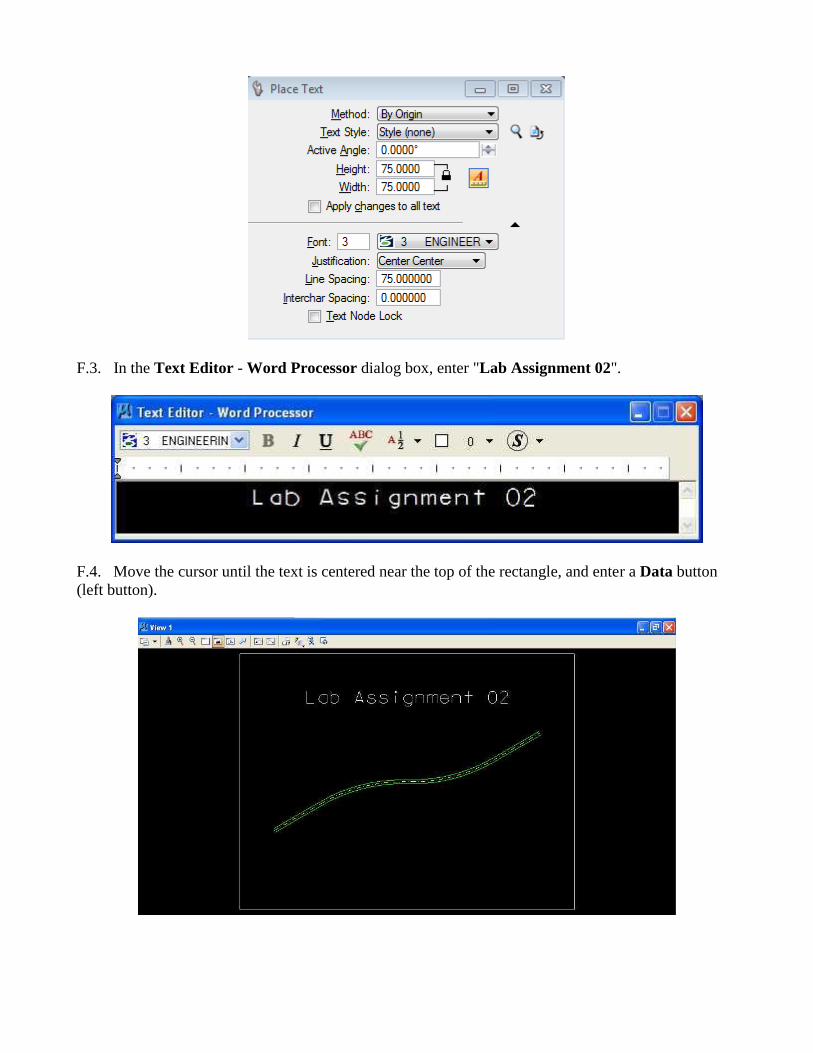
F.3. In the Text Editor - Word Processor dialog box, enter "Lab Assignment 02".
F.4. Move the cursor until the text is centered near the top of the rectangle, and enter a Data button
(left button).
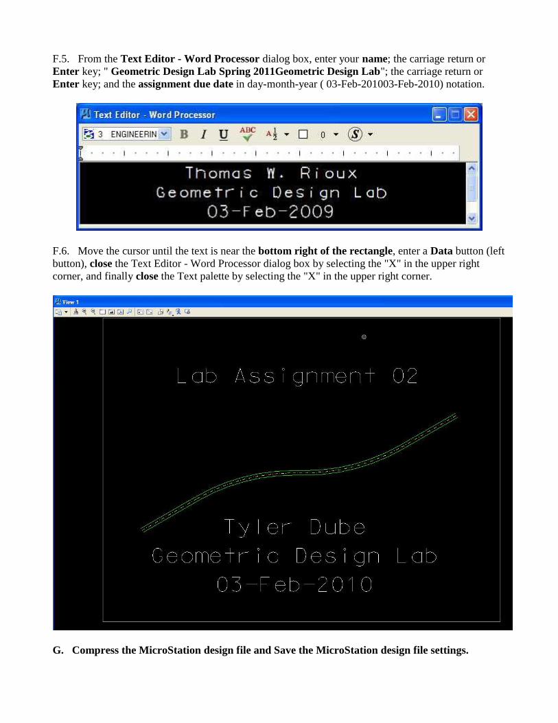
F.5. From the Text Editor - Word Processor dialog box, enter your name; the carriage return or
Enter key; " Geometric Design Lab Spring 2011Geometric Design Lab"; the carriage return or
Enter key; and the assignment due date in day-month-year ( 03-Feb-201003-Feb-2010) notation.
F.6. Move the cursor until the text is near the bottom right of the rectangle, enter a Data button (left
button), close the Text Editor - Word Processor dialog box by selecting the "X" in the upper right
corner, and finally close the Text palette by selecting the "X" in the upper right corner.
G. Compress the MicroStation design file and Save the MicroStation design file settings.

G.1. In the MicroStation dialog box, choose File -> Compress -> Design.
G.2. In the MicroStation dialog box, choose File -> Save Settings.
H. Select the black and white laser printer as the default printer.
H.1. From the Windows Start Menu in the lower left corner of the screen, choose Start -> Printers
and Faxes.
H.2. In the Printers and Faxes dialog box, Select ENGR-SC2-Laser-2ENGR-SC2-Laser-2, choose
File -> Set as Default Printer, then close the dialog box by pressing the red "X" in the upper right
corner of the dialog box.
I. Place a fence around the rectangle and print the drawing.
I.1. From the MicroStation tool palette, choose the Fence palette (top row right icon) and open it as a
tool box in the MicroStation View 1 window.
I.2. From the Fence palette, choose the Place icon (leftmost icon) . From the Place Fence dialog
box, choose Fence Type = Element and Fence Mode = Inside; then select the rectangle enclosing the
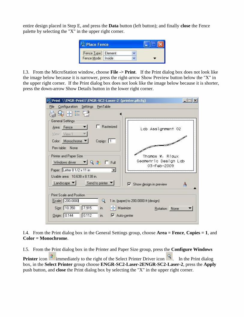
entire design placed in Step E, and press the Data button (left button); and finally close the Fence
palette by selecting the "X" in the upper right corner.
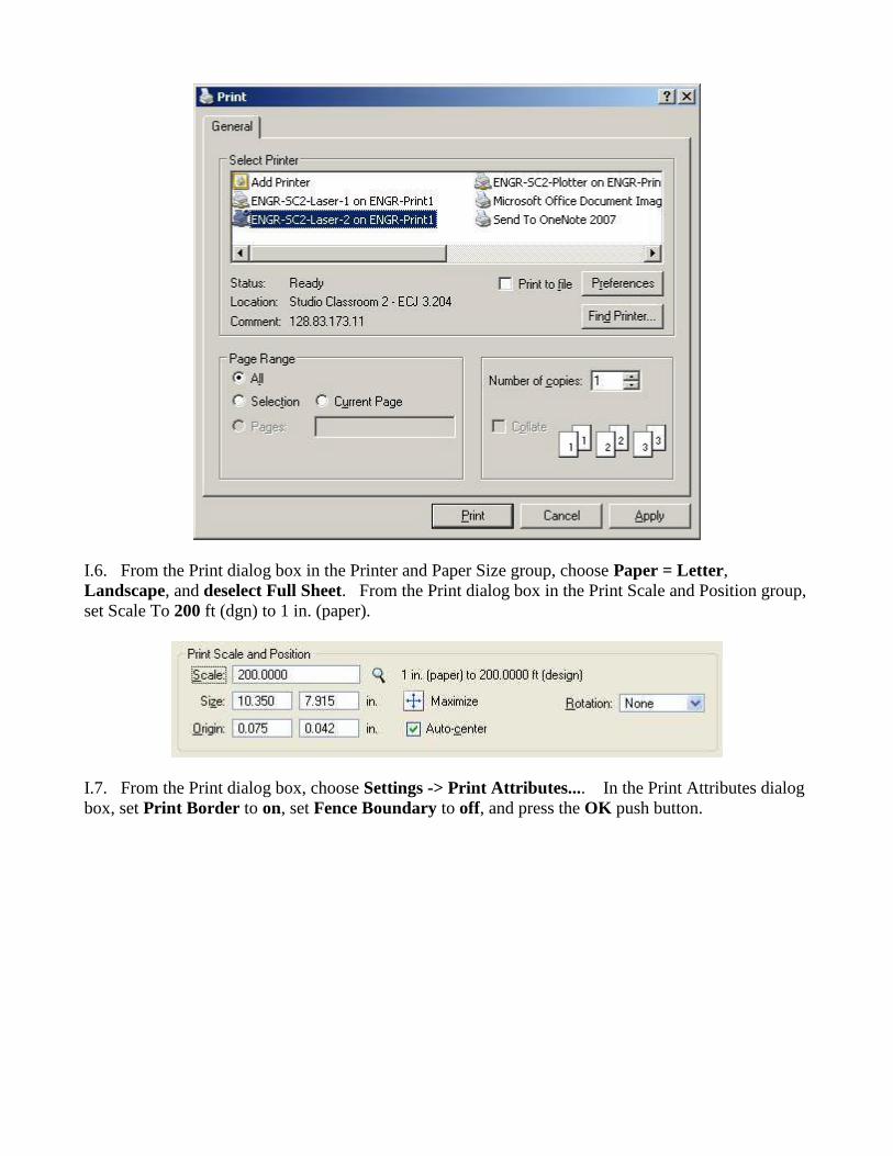
I.3. From the MicroStation window, choose File -> Print. If the Print dialog box does not look like
the image below because it is narrower, press the right-arrow Show Preview button below the "X" in
the upper right corner. If the Print dialog box does not look like the image below because it is shorter,
press the down-arrow Show Details button in the lower right corner.
I.4. From the Print dialog box in the General Settings group, choose Area = Fence, Copies = 1, and
Color = Monochrome.
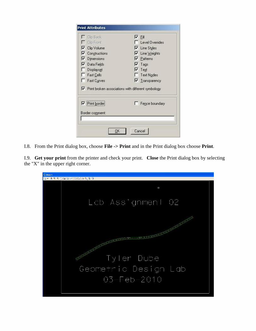
I.5. From the Print dialog box in the Printer and Paper Size group, press the Configure Windows
Printer icon immediately to the right of the Select Printer Driver icon . In the Print dialog
box, in the Select Printer group choose ENGR-SC2-Laser-2ENGR-SC2-Laser-2, press the Apply
push button, and close the Print dialog box by selecting the "X" in the upper right corner.
I.6. From the Print dialog box in the Printer and Paper Size group, choose Paper = Letter,
Landscape, and deselect Full Sheet. From the Print dialog box in the Print Scale and Position group,
set Scale To 200 ft (dgn) to 1 in. (paper).
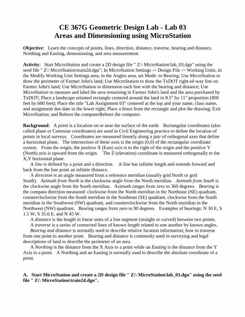
I.7. From the Print dialog box, choose Settings -> Print Attributes.... In the Print Attributes dialog
box, set Print Border to on, set Fence Boundary to off, and press the OK push button.
I.8. From the Print dialog box, choose File -> Print and in the Print dialog box choose Print.
I.9. Get your print from the printer and check your print. Close the Print dialog box by selecting
the "X" in the upper right corner.

Leg Centerline and Lanes Print
J. Exit MicroStation.
J.1. In the MicroStation dialog box, choose File -> Compress -> Design.
J.2. In the MicroStation dialog box, choose File -> Save Settings.
J.3. In the MicroStation dialog box, choose File -> Exit.
K. Reboot the computer.
CE367G Geometric Design Lab web page
Original Copyright © 2009 by Dr. Thomas W. Rioux
Edited by Neil Quarles & Krishna Murthy Gurumurthy, 2017
CE 367G Geometric Design Lab - Lab 03
Areas and Dimensioning using MicroStation
Objective: Learn the concepts of points, lines, direction, distance, traverse, bearing and distance,
Northing and Easting, dimensioning, and area measurement.
Activity: Start MicroStation and create a 2D design file " Z:\ MicroStation\lab_03.dgn" using the
seed file " Z:\ MicroStation\train2d.dgn"; In MicroStation Settings -> Design File -> Working Units, in
the Modify Working Unit Settings area, in the Angles area, set Mode: to Bearing; Use MicroStation to
draw the perimeter of Farmer John's land; Use MicroStation to draw the TxDOT right-of-way line on
Farmer John's land; Use MicroStation to dimension each line with the bearing and distance; Use
MicroStation to measure and label the area remaining in Farmer John's land and the area purchased by
TxDOT; Place a landscape oriented rectangle centered around the land in 8.5" by 11" proportion (800
feet by 600 feet); Place the title "Lab Assignment 03" centered at the top and your name, class name,
and assignment due date in the lower right; Place a fence from the rectangle and plot the drawing; Exit
MicroStation; and Reboot the computerReboot the computer.
Background: A point is a location on or near the surface of the earth. Rectangular coordinates (also
called plane or Cartesian coordinates) are used in Civil Engineering practice to define the location of
points in local surveys. Coordinates are measured linearly along a pair of orthogonal axes that define
a horizontal plane. The intersection of these axes is the origin (0,0) of the rectangular coordinate
system. From the origin, the positive X (East) axis is to the right of the origin and the positive Y
(North) axis is upward from the origin. The Z (elevation) coordinate is measured orthogonally to the
X,Y horizontal plane.
A line is defined by a point and a direction. A line has infinite length and extends forward and
back from the line point an infinite distance.
A direction is an angle measured from a reference meridian (usually grid North or grid
South). Azimuth from North is the clockwise angle from the North meridian. Azimuth from South is
the clockwise angle from the South meridian. Azimuth ranges from zero to 360 degrees. Bearing is
the compass direction measured: clockwise from the North meridian in the Northeast (NE) quadrant,
counterclockwise from the South meridian in the Southeast (SE) quadrant, clockwise from the South
meridian in the Southwest (SW) quadrant, and counterclockwise from the North meridian in the
Northwest (NW) quadrant. Bearing ranges from zero to 90 degrees. Examples of bearings: N 30 E, S
1.5 W, S 35.6 E, and N 45 W.
A distance is the length in linear units of a line segment (straight or curved) between two points.
A traverse is a series of connected lines of known length related to one another by known angles.
Bearing and distance is normally used to describe relative location information; how to traverse
from one point to another point. Bearing and distance is commonly used in surveying and legal
descriptions of land to describe the perimeter of an area.
A Northing is the distance from the X Axis to a point while an Easting is the distance from the Y
Axis to a point. A Northing and an Easting is normally used to describe the absolute coordinate of a
point.
A. Start MicroStation and create a 2D design file " Z:\ MicroStation\lab_03.dgn" using the seed
file " Z:\ MicroStation\train2d.dgn".

B. In MicroStation Settings -> Design File -> Angle Readout, in the Direction area, set Mode: to
Bearing.
C. Use MicroStation to draw the perimeter of Farmer John's land. Farmer John’s land starts at a
point North 150 feet and East 300 feet, thence 305 feet North 1.5 degrees East, thence 400 feet North
89 degrees East, thence 300 feet South 2.4 degrees East, and finally back to the starting point. Farmer
John’s land is 124,035.7304 square feet.
C.1. Set the active level to Default (level=Default), color to green (color=2), style to solid
(style=0), and weight to 0 (weight=0).
C.2. Draw a line starting at North 150 feet and East 300 feet and traversing 305 feet North 1.5
degrees East.
C.2.a. From the MicroStation Main Tool menu, select the Linear Elements palette (row 2 right icon)
and open it as a tool box in the MicroStation View 1 window.
C.2.b. From the Linear Elements palette, choose the Place Line icon (2nd from left on the top row).
C.2.c. In the MicroStation Key-in field, enter "xy=300,150" plus a carriage return or the Enter
key. For more information on MicroStation key-ins, in the MicroStation dialog box, choose Help ->
Contents, then choose the Search tab, then enter precision, then press the List Topics push button,
then double-click on Precision Input Key-ins, read the help information, and finally close the help
dialog box.
C.2.d. In the MicroStation Key-in field, enter "di=305,N 1.5 E" plus a carriage return or the Enter
key (be sure that you type a blank between the "N" and the "1.5" and between the "1.5" and the "E").
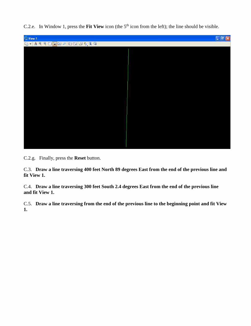
C.2.e. In Window 1, press the Fit View icon (the 5th icon from the left); the line should be visible.
C.2.g. Finally, press the Reset button.
C.3. Draw a line traversing 400 feet North 89 degrees East from the end of the previous line and
fit View 1.
C.4. Draw a line traversing 300 feet South 2.4 degrees East from the end of the previous line
and fit View 1.
C.5. Draw a line traversing from the end of the previous line to the beginning point and fit View
1.
7
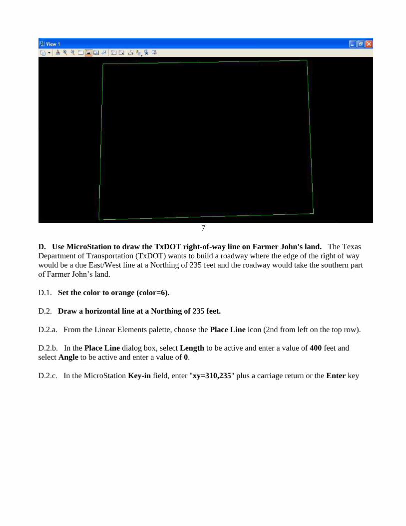
D. Use MicroStation to draw the TxDOT right-of-way line on Farmer John's land. The Texas
Department of Transportation (TxDOT) wants to build a roadway where the edge of the right of way
would be a due East/West line at a Northing of 235 feet and the roadway would take the southern part
of Farmer John’s land.
D.1. Set the color to orange (color=6).
D.2. Draw a horizontal line at a Northing of 235 feet.
D.2.a. From the Linear Elements palette, choose the Place Line icon (2nd from left on the top row).
D.2.b. In the Place Line dialog box, select Length to be active and enter a value of 400 feet and
select Angle to be active and enter a value of 0.
D.2.c. In the MicroStation Key-in field, enter "xy=310,235" plus a carriage return or the Enter key
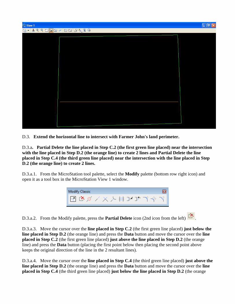
D.3. Extend the horizontal line to intersect with Farmer John's land perimeter.
D.3.a. Partial Delete the line placed in Step C.2 (the first green line placed) near the intersection
with the line placed in Step D.2 (the orange line) to create 2 lines and Partial Delete the line
placed in Step C.4 (the third green line placed) near the intersection with the line placed in Step
D.2 (the orange line) to create 2 lines.
D.3.a.1. From the MicroStation tool palette, select the Modify palette (bottom row right icon) and
open it as a tool box in the MicroStation View 1 window.
D.3.a.2. From the Modify palette, press the Partial Delete icon (2nd icon from the left) .
D.3.a.3. Move the cursor over the line placed in Step C.2 (the first green line placed) just below the
line placed in Step D.2 (the orange line) and press the Data button and move the cursor over the line
placed in Step C.2 (the first green line placed) just above the line placed in Step D.2 (the orange
line) and press the Data button (placing the first point below then placing the second point above
keeps the original direction of the line in the 2 resultant lines).
D.3.a.4. Move the cursor over the line placed in Step C.4 (the third green line placed) just above the
line placed in Step D.2 (the orange line) and press the Data button and move the cursor over the line
placed in Step C.4 (the third green line placed) just below the line placed in Step D.2 (the orange
line) and press the Data button (placing the first point above then placing the second point below
keeps the original direction of the line in the 2 resultant lines).
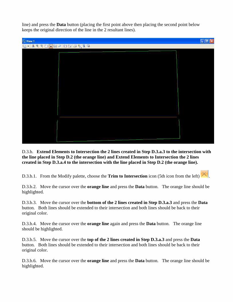
D.3.b. Extend Elements to Intersection the 2 lines created in Step D.3.a.3 to the intersection with
the line placed in Step D.2 (the orange line) and Extend Elements to Intersection the 2 lines
created in Step D.3.a.4 to the intersection with the line placed in Step D.2 (the orange line).
D.3.b.1. From the Modify palette, choose the Trim to Intersection icon (5th icon from the left) .
D.3.b.2. Move the cursor over the orange line and press the Data button. The orange line should be
highlighted.
D.3.b.3. Move the cursor over the bottom of the 2 lines created in Step D.3.a.3 and press the Data
button. Both lines should be extended to their intersection and both lines should be back to their
original color.
D.3.b.4. Move the cursor over the orange line again and press the Data button. The orange line
should be highlighted.
D.3.b.5. Move the cursor over the top of the 2 lines created in Step D.3.a.3 and press the Data
button. Both lines should be extended to their intersection and both lines should be back to their
original color.
D.3.b.6. Move the cursor over the orange line and press the Data button. The orange line should be
highlighted.
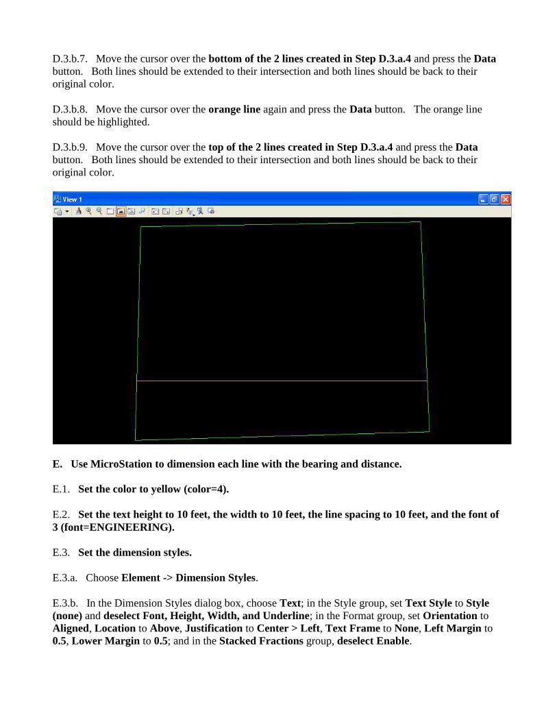
D.3.b.7. Move the cursor over the bottom of the 2 lines created in Step D.3.a.4 and press the Data
button. Both lines should be extended to their intersection and both lines should be back to their
original color.
D.3.b.8. Move the cursor over the orange line again and press the Data button. The orange line
should be highlighted.
D.3.b.9. Move the cursor over the top of the 2 lines created in Step D.3.a.4 and press the Data
button. Both lines should be extended to their intersection and both lines should be back to their
original color.
E. Use MicroStation to dimension each line with the bearing and distance.
E.1. Set the color to yellow (color=4).
E.2. Set the text height to 10 feet, the width to 10 feet, the line spacing to 10 feet, and the font of
3 (font=ENGINEERING).
E.3. Set the dimension styles.
E.3.a. Choose Element -> Dimension Styles.
E.3.b. In the Dimension Styles dialog box, choose Text; in the Style group, set Text Style to Style
(none) and deselect Font, Height, Width, and Underline; in the Format group, set Orientation to
Aligned, Location to Above, Justification to Center > Left, Text Frame to None, Left Margin to
0.5, Lower Margin to 0.5; and in the Stacked Fractions group, deselect Enable.
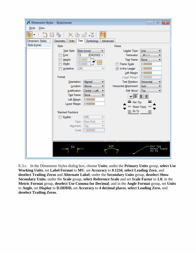
E.3.c. In the Dimension Styles dialog box, choose Units; under the Primary Units group, select Use
Working Units, set Label Format to MU, set Accuracy to 0.1234, select Leading Zero, and
deselect Trailing Zeros and Alternate Label; under the Secondary Units group, deselect Show
Secondary Units; under the Scale group, select Reference Scale and set Scale Factor to 1.0; in the
Metric Format group, deselect Use Comma for Decimal; and in the Angle Format group, set Units
to Angle, set Display to D.DDDD, set Accuracy to 4 decimal places, select Leading Zero, and
deselect Trailing Zeros.
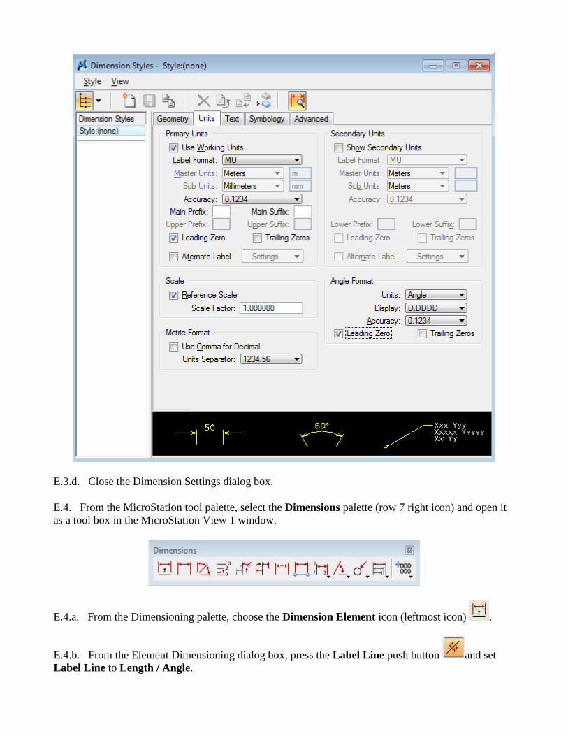
E.3.d. Close the Dimension Settings dialog box.
E.4. From the MicroStation tool palette, select the Dimensions palette (row 7 right icon) and open it
as a tool box in the MicroStation View 1 window.
E.4.a. From the Dimensioning palette, choose the Dimension Element icon (leftmost icon) .
E.4.b. From the Element Dimensioning dialog box, press the Label Line push button and set
Label Line to Length / Angle.
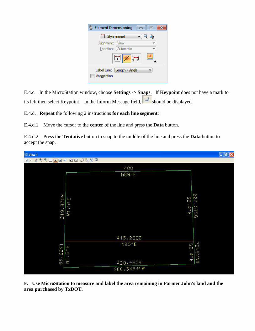
E.4.c. In the MicroStation window, choose Settings -> Snaps. If Keypoint does not have a mark to
its left then select Keypoint. In the Inform Message field, should be displayed.
E.4.d. Repeat the following 2 instructions for each line segment:
E.4.d.1. Move the cursor to the center of the line and press the Data button.
E.4.d.2 Press the Tentative button to snap to the middle of the line and press the Data button to
accept the snap.
F. Use MicroStation to measure and label the area remaining in Farmer John's land and the
area purchased by TxDOT.
F.1. From the MicroStation tool palette, select the Measure palette (row 7 left icon) and open it as a
tool box in the MicroStation View 1 window.
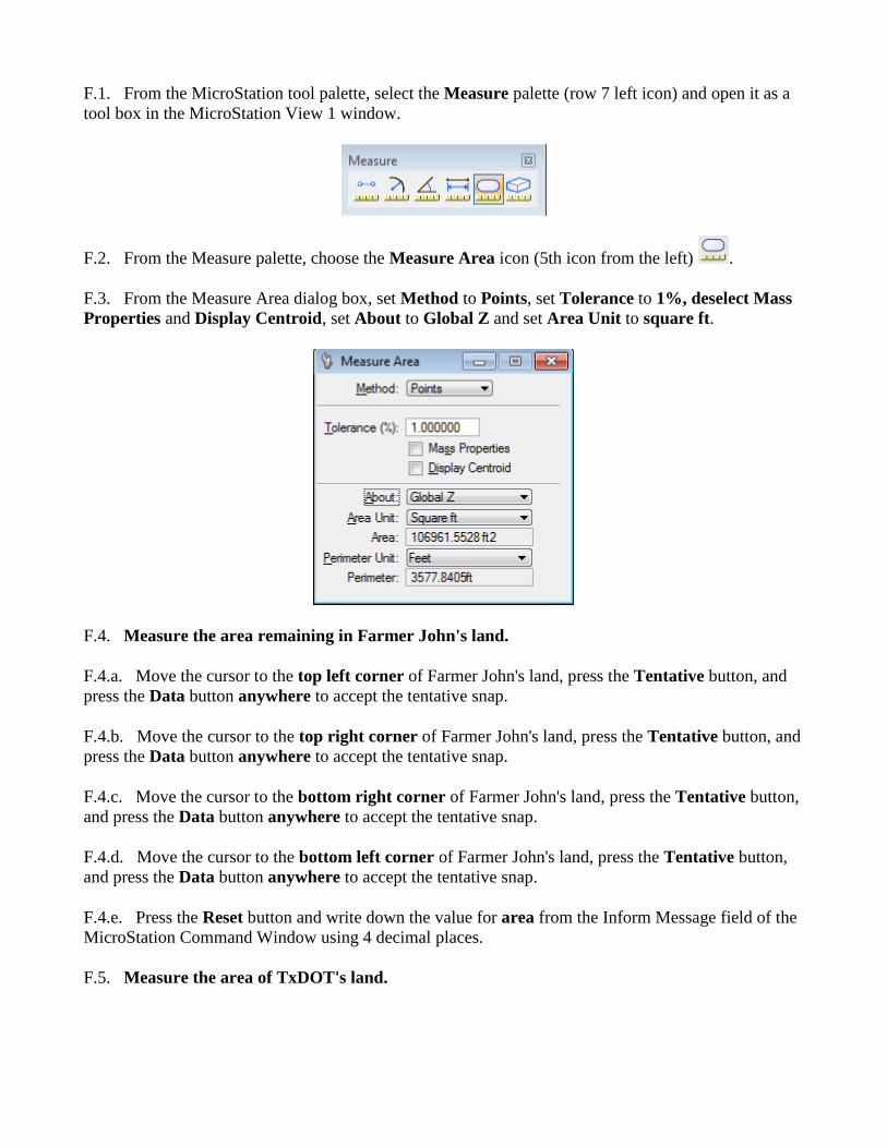
F.2. From the Measure palette, choose the Measure Area icon (5th icon from the left) .
F.3. From the Measure Area dialog box, set Method to Points, set Tolerance to 1%, deselect Mass
Properties and Display Centroid, set About to Global Z and set Area Unit to square ft.
F.4. Measure the area remaining in Farmer John's land.
F.4.a. Move the cursor to the top left corner of Farmer John's land, press the Tentative button, and
press the Data button anywhere to accept the tentative snap.
F.4.b. Move the cursor to the top right corner of Farmer John's land, press the Tentative button, and
press the Data button anywhere to accept the tentative snap.
F.4.c. Move the cursor to the bottom right corner of Farmer John's land, press the Tentative button,
and press the Data button anywhere to accept the tentative snap.
F.4.d. Move the cursor to the bottom left corner of Farmer John's land, press the Tentative button,
and press the Data button anywhere to accept the tentative snap.
F.4.e. Press the Reset button and write down the value for area from the Inform Message field of the
MicroStation Command Window using 4 decimal places.
F.5. Measure the area of TxDOT's land.
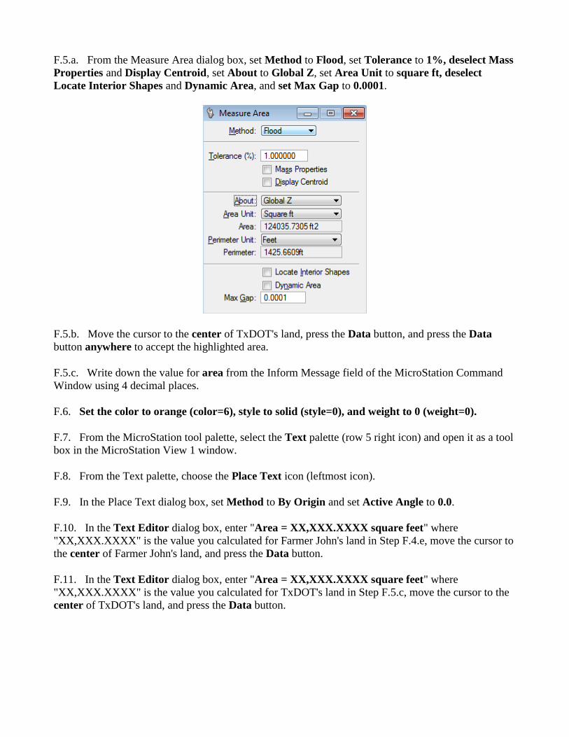
F.5.a. From the Measure Area dialog box, set Method to Flood, set Tolerance to 1%, deselect Mass
Properties and Display Centroid, set About to Global Z, set Area Unit to square ft, deselect
Locate Interior Shapes and Dynamic Area, and set Max Gap to 0.0001.
F.5.b. Move the cursor to the center of TxDOT's land, press the Data button, and press the Data
button anywhere to accept the highlighted area.
F.5.c. Write down the value for area from the Inform Message field of the MicroStation Command
Window using 4 decimal places.
F.6. Set the color to orange (color=6), style to solid (style=0), and weight to 0 (weight=0).
F.7. From the MicroStation tool palette, select the Text palette (row 5 right icon) and open it as a tool
box in the MicroStation View 1 window.
F.8. From the Text palette, choose the Place Text icon (leftmost icon).
F.9. In the Place Text dialog box, set Method to By Origin and set Active Angle to 0.0.
F.10. In the Text Editor dialog box, enter "Area = XX,XXX.XXXX square feet" where
"XX,XXX.XXXX" is the value you calculated for Farmer John's land in Step F.4.e, move the cursor to
the center of Farmer John's land, and press the Data button.
F.11. In the Text Editor dialog box, enter "Area = XX,XXX.XXXX square feet" where
"XX,XXX.XXXX" is the value you calculated for TxDOT's land in Step F.5.c, move the cursor to the
center of TxDOT's land, and press the Data button.
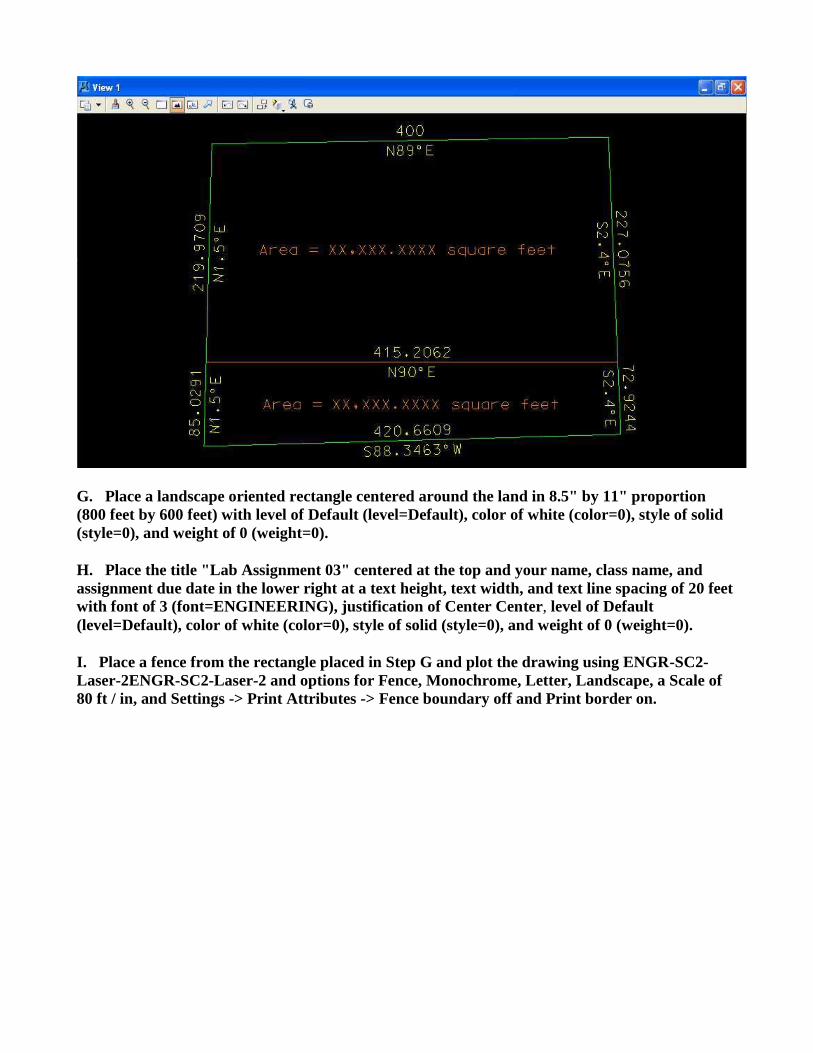
G. Place a landscape oriented rectangle centered around the land in 8.5" by 11" proportion
(800 feet by 600 feet) with level of Default (level=Default), color of white (color=0), style of solid
(style=0), and weight of 0 (weight=0).
H. Place the title "Lab Assignment 03" centered at the top and your name, class name, and
assignment due date in the lower right at a text height, text width, and text line spacing of 20 feet
with font of 3 (font=ENGINEERING), justification of Center Center, level of Default
(level=Default), color of white (color=0), style of solid (style=0), and weight of 0 (weight=0).
I. Place a fence from the rectangle placed in Step G and plot the drawing using ENGR-SC2-
Laser-2ENGR-SC2-Laser-2 and options for Fence, Monochrome, Letter, Landscape, a Scale of
80 ft / in, and Settings -> Print Attributes -> Fence boundary off and Print border on.
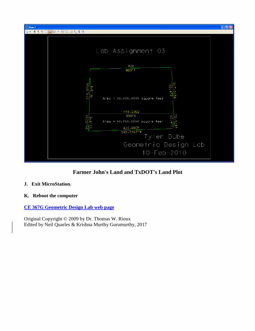
Farmer John's Land and TxDOT's Land Plot
J. Exit MicroStation.
K. Reboot the computer
CE 367G Geometric Design Lab web page
Original Copyright © 2009 by Dr. Thomas W. Rioux
Edited by Neil Quarles & Krishna Murthy Gurumurthy, 2017
CE 367G Geometric Design Lab - Lab 04
Pavement Edge Design with a Simple Arc of a Circle and with a
Taper Section and an Arc of a Circle using MicroStation
Objective: Learn pavement edge design and vehicle offtracking concepts using IGIDS-created
vehicle turn template. Observe the reduction in circular arc radius and area when a taper section is
added.
Activity: Copy the MicroStation Cell Library file "bus_template.cel" to " Z:\ MicroStation"; Start
MicroStation and create a 2D design file " Z:\ MicroStation\lab_04.dgn" using the seed file " Z:\
MicroStation\train2d.dgn"; Use MicroStation to draw the legs of the intersection; Attach the cell file
"bus_template.cel"; Place the IGIDS BUS Template cell; Construct a circular arc curb return; Use
MicroStation to draw the 1:10 taper section line; Use MicroStation to construct a circular arc pavement
edge; Use MicroStation to extend the taper section line to the green circular arc; Use MicroStation to
measure, crosshatch, and dimension the area between the two pavement edges; Use MicroStation to
dimension the two circular arcs and the taper section; Turn Default display on; Place a landscape
oriented rectangle centered around the intersection in 8.5" by 11" proportion (230 feet by 180 feet);
Place the title "Lab Assignment 04" at the top right and your name, class name, and assignment due
date in the lower right; Place a fence from the rectangle and plot the drawing; Exit MicroStation; and
Reboot the computerReboot the computer.
Background: The California Department of Transportation (CALTRANS) developed the Truck
Offtracking Model (TOM), a computer model of vehicle offtracking. The Texas State Department of
Transportation (TxDOT) modified TOM and called it TXTOM. TXTOM was used to generate the
vehicle turn templates found in the American Association of State Highway and Transportation
Officials (AASHTO) design policy. The Center for Transportation Research at The University of
Texas at Austin converted TXTOM from FORTRAN to C, added metric units, added metric
parameters for the design vehicles, and incorporated TXTOM in the Interactive Graphics Intersection
Design System (IGIDS). For the standard AASHTO design vehicles, vehicle turning templates may be
quickly drawn to a user-specified turn radius for the turn angle between adjacent, user-selected
legs. The position of the outer edge of the front bumper and the inner edge of the rear axle are
calculated as the outer edge of the front axle is moved in 1-foot (0.3048-foot) increments along a
circular arc. An optional clearance zone in yellow may be specified that is calculated the specified
distance outside the outer edge of the front bumper and inside the inner edge of the rear axle. These
templates are created as a MicroStation Cell. A MicroStation Cell is a group of elements with an
optional placement origin which can be manipulated as a single element. A MicroStation Cell is
contained in a MicroStation Cell Library which can have one or more MicroStation Cells. These
templates may be moved dynamically over the intersection geometry to evaluate pavement edge and
channelization requirements.
A taper section is a line segment at a shallow angle to the pavement edge expressed as a ratio of lateral
distance to longitudinal distance, usually in the range of 1:10 to 1:15. The taper section may precede
and/or follow the circular arc. The use of taper sections can facilitate fitting the pavement edge to the
offtracking path of a selected design vehicle and generally reduces the radius of the circular arc.

A. Copy the MicroStation Cell Library file "bus_template.cel" to " Z:\ MicroStation" .
A.1. Download the ‘bus_template.cel’ file to your Microstation folder. This file is located in Canvas
B. Start MicroStation and create a 2D design file " Z:\ MicroStation\lab_04.dgn" using the seed
file " Z:\ MicroStation\train2d.dgn".
C. Use MicroStation to draw the legs of the intersection.
C.1. Set the color to white (color=0), the style to solid (style=0), and the weight to 0 (weight=0).
C.2. From point 5000,5000, draw a 150 foot line at an angle of 270 degrees (Line A).
C.3. From point 5000,5000, draw a 200 foot line at an angle of 345 degrees (Line B).
C.4. Copy Line A a distance of 15 feet parallel to the right (Line C).
C.5. Copy Line B a distance of 15 feet parallel to the bottom (Line D).
C.6. Extend lines C and D to their intersection.
C.7. Copy Line C a distance of 1.5 feet parallel to the left (Line E).
C.8. Copy Line D a distance of 1.5 feet parallel to the top (Line F).
C.9. Change the color of Line E and Line F to blue (color=1).
C.10. Fit window 1.
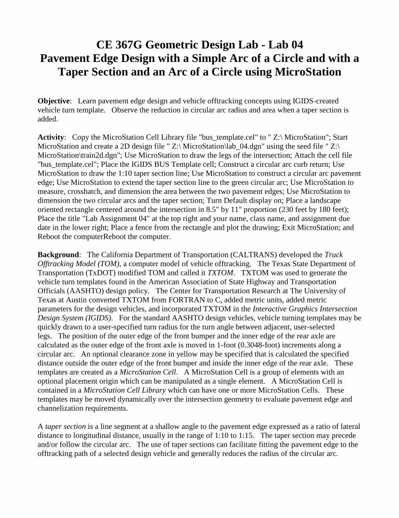
D. Attach the cell file "bus_template.cel".
D.1 Download the ‘bus_template.cel’ file from Canvas or the project website to your Microstation
folder.
D.1. From the MicroStation dialog box, choose Element -> Cells.
D.2. In the Cell Library: [NONE] dialog box, choose File -> Attach File.
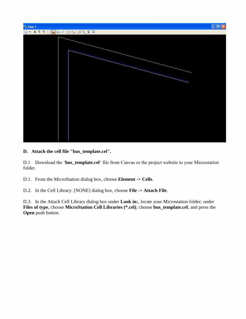
D.3. In the Attach Cell Library dialog box under Look in:, locate your Microstation folder; under
Files of type, choose MicroStation Cell Libraries (*.cel); choose bus_template.cel; and press the
Open push button.
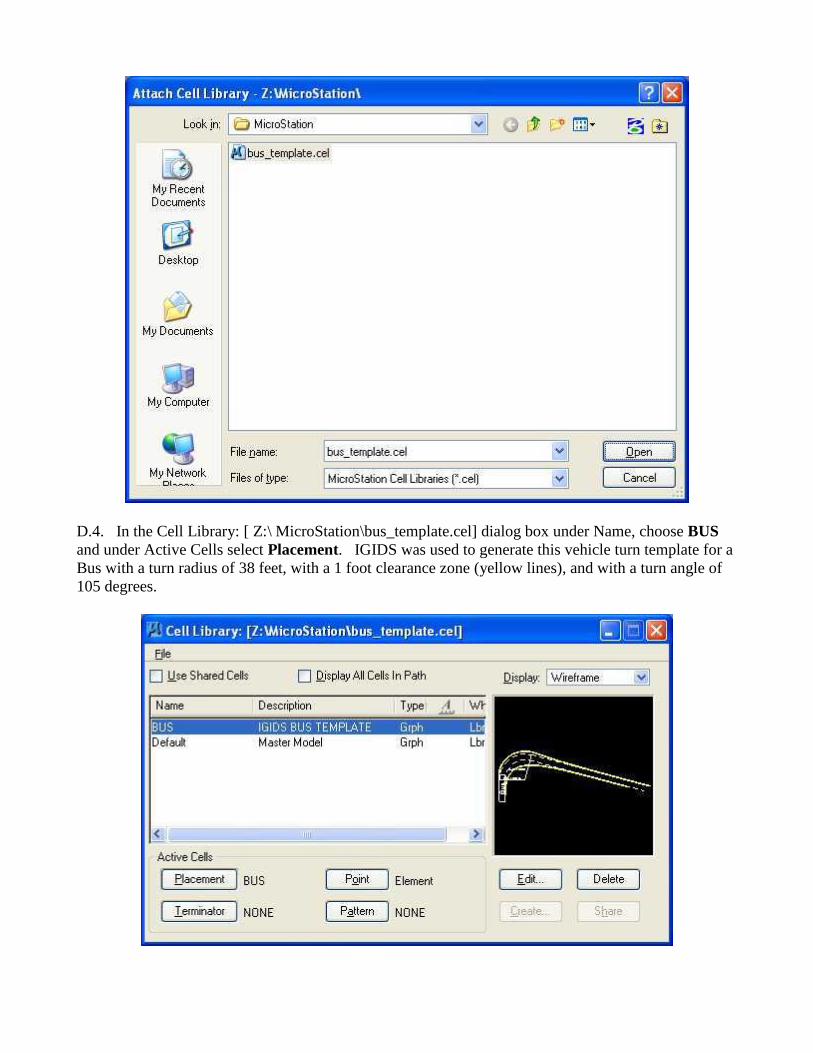
D.4. In the Cell Library: [ Z:\ MicroStation\bus_template.cel] dialog box under Name, choose BUS
and under Active Cells select Placement. IGIDS was used to generate this vehicle turn template for a
Bus with a turn radius of 38 feet, with a 1 foot clearance zone (yellow lines), and with a turn angle of
105 degrees.
D.5. Close the Cell Library: [ Z:\ MicroStation\bus_template.cel] dialog box by pressing in the
upper right corner.
D.6. From the MicroStation dialog box, choose File -> Save Settings.
E. Place the IGIDS BUS Template cell on Default (level=Default).
Note: It's important to set working units to feet and resolution to 1000000 per foot before placing
the cell (see section C.10 in lab 01).
E.1. Set the active level to Default (level=Default).
E.2. From the MicroStation Main Tool menu, select the Cells palette (6th row right icon).
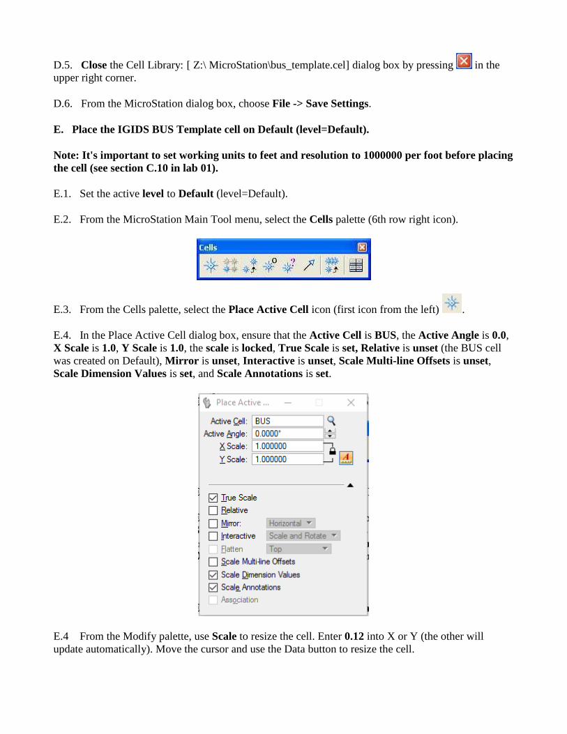
E.3. From the Cells palette, select the Place Active Cell icon (first icon from the left) .
E.4. In the Place Active Cell dialog box, ensure that the Active Cell is BUS, the Active Angle is 0.0,
X Scale is 1.0, Y Scale is 1.0, the scale is locked, True Scale is set, Relative is unset (the BUS cell
was created on Default), Mirror is unset, Interactive is unset, Scale Multi-line Offsets is unset,
Scale Dimension Values is set, and Scale Annotations is set.
E.4 From the Modify palette, use Scale to resize the cell. Enter 0.12 into X or Y (the other will
update automatically). Move the cursor and use the Data button to resize the cell.
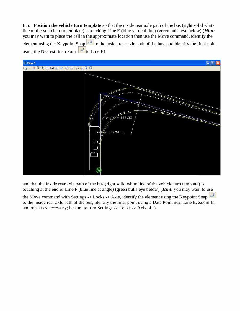
E.5. Position the vehicle turn template so that the inside rear axle path of the bus (right solid white
line of the vehicle turn template) is touching Line E (blue vertical line) (green bulls eye below) (Hint:
you may want to place the cell in the approximate location then use the Move command, identify the
element using the Keypoint Snap to the inside rear axle path of the bus, and identify the final point
using the Nearest Snap Point to Line E)
and that the inside rear axle path of the bus (right solid white line of the vehicle turn template) is
touching at the end of Line F (blue line at angle) (green bulls eye below) (Hint: you may want to use
the Move command with Settings -> Locks -> Axis, identify the element using the Keypoint Snap
to the inside rear axle path of the bus, identify the final point using a Data Point near Line E, Zoom In,
and repeat as necessary; be sure to turn Settings -> Locks -> Axis off ).
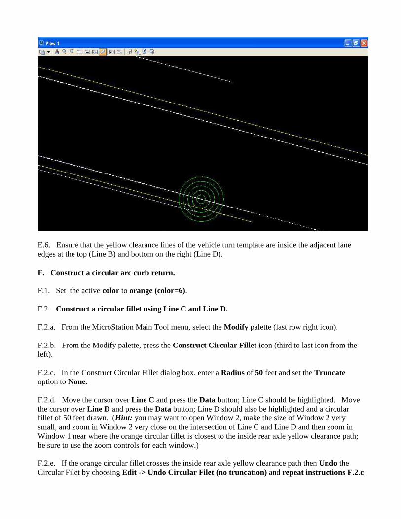
E.6. Ensure that the yellow clearance lines of the vehicle turn template are inside the adjacent lane
edges at the top (Line B) and bottom on the right (Line D).
F. Construct a circular arc curb return.
F.1. Set the active color to orange (color=6).
F.2. Construct a circular fillet using Line C and Line D.
F.2.a. From the MicroStation Main Tool menu, select the Modify palette (last row right icon).
F.2.b. From the Modify palette, press the Construct Circular Fillet icon (third to last icon from the
left).
F.2.c. In the Construct Circular Fillet dialog box, enter a Radius of 50 feet and set the Truncate
option to None.
F.2.d. Move the cursor over Line C and press the Data button; Line C should be highlighted. Move
the cursor over Line D and press the Data button; Line D should also be highlighted and a circular
fillet of 50 feet drawn. (Hint: you may want to open Window 2, make the size of Window 2 very
small, and zoom in Window 2 very close on the intersection of Line C and Line D and then zoom in
Window 1 near where the orange circular fillet is closest to the inside rear axle yellow clearance path;
be sure to use the zoom controls for each window.)
F.2.e. If the orange circular fillet crosses the inside rear axle yellow clearance path then Undo the
Circular Filet by choosing Edit -> Undo Circular Filet (no truncation) and repeat instructions F.2.c
through F.2.d changing the radius in 5-foot increments and then 1-foot increments and then 0.1-foot
increments until the minimum radius orange circular fillet is found that does not cross the inside rear
axle yellow clearance path.
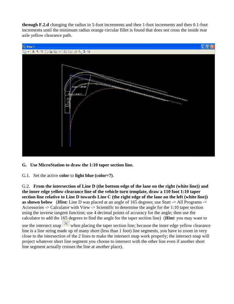
G. Use MicroStation to draw the 1:10 taper section line.
G.1. Set the active color to light blue (color=7).
G.2. From the intersection of Line D (the bottom edge of the lane on the right (white line)) and
the inner edge yellow clearance line of the vehicle turn template, draw a 110 foot 1:10 taper
section line relative to Line D towards Line C (the right edge of the lane on the left (white line))
as shown below (Hint: Line D was placed at an angle of 165 degrees; use Start -> All Programs ->
Accessories -> Calculator with View -> Scientific to determine the angle for the 1:10 taper section
using the inverse tangent function; use 4 decimal points of accuracy for the angle; then use the
calculator to add the 165 degrees to find the angle for the taper section line) (Hint: you may want to
use the intersect snap when placing the taper section line; because the inner edge yellow clearance
line is a line string made up of many short (less than 1 foot) line segments, you have to zoom in very
close to the intersection of the 2 lines to make the intersect snap work properly; the intersect snap will
project whatever short line segment you choose to intersect with the other line even if another short
line segment actually crosses the line at another place).
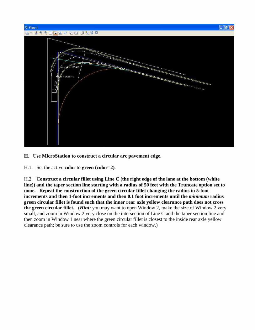
H. Use MicroStation to construct a circular arc pavement edge.
H.1. Set the active color to green (color=2).
H.2. Construct a circular fillet using Line C (the right edge of the lane at the bottom (white
line)) and the taper section line starting with a radius of 50 feet with the Truncate option set to
none. Repeat the construction of the green circular fillet changing the radius in 5-foot
increments and then 1-foot increments and then 0.1 foot increments until the minimum radius
green circular fillet is found such that the inner rear axle yellow clearance path does not cross
the green circular fillet. (Hint: you may want to open Window 2, make the size of Window 2 very
small, and zoom in Window 2 very close on the intersection of Line C and the taper section line and
then zoom in Window 1 near where the green circular fillet is closest to the inside rear axle yellow
clearance path; be sure to use the zoom controls for each window.)
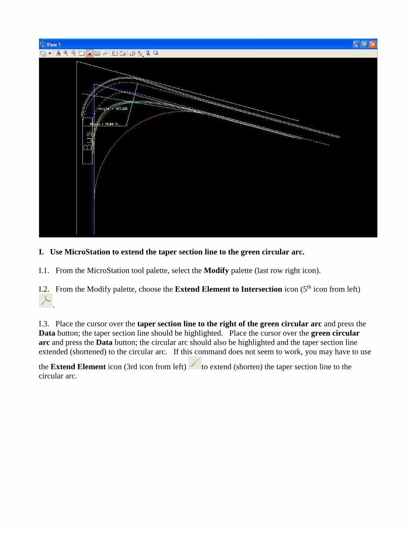
I. Use MicroStation to extend the taper section line to the green circular arc.
I.1. From the MicroStation tool palette, select the Modify palette (last row right icon).
I.2. From the Modify palette, choose the Extend Element to Intersection icon (5th icon from left)
.
I.3. Place the cursor over the taper section line to the right of the green circular arc and press the
Data button; the taper section line should be highlighted. Place the cursor over the green circular
arc and press the Data button; the circular arc should also be highlighted and the taper section line
extended (shortened) to the circular arc. If this command does not seem to work, you may have to use
the Extend Element icon (3rd icon from left) to extend (shorten) the taper section line to the
circular arc.
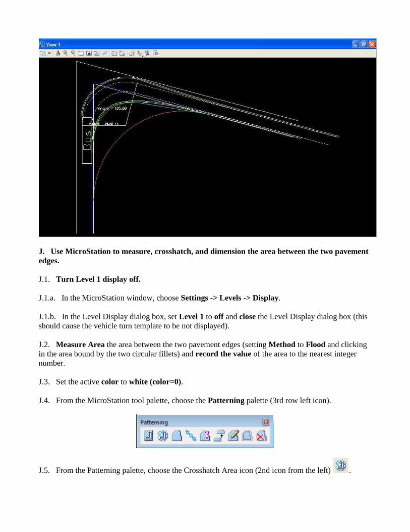
J. Use MicroStation to measure, crosshatch, and dimension the area between the two pavement
edges.
J.1. Turn Level 1 display off.
J.1.a. In the MicroStation window, choose Settings -> Levels -> Display.
J.1.b. In the Level Display dialog box, set Level 1 to off and close the Level Display dialog box (this
should cause the vehicle turn template to be not displayed).
J.2. Measure Area the area between the two pavement edges (setting Method to Flood and clicking
in the area bound by the two circular fillets) and record the value of the area to the nearest integer
number.
J.3. Set the active color to white (color=0).
J.4. From the MicroStation tool palette, choose the Patterning palette (3rd row left icon).
J.5. From the Patterning palette, choose the Crosshatch Area icon (2nd icon from the left) .
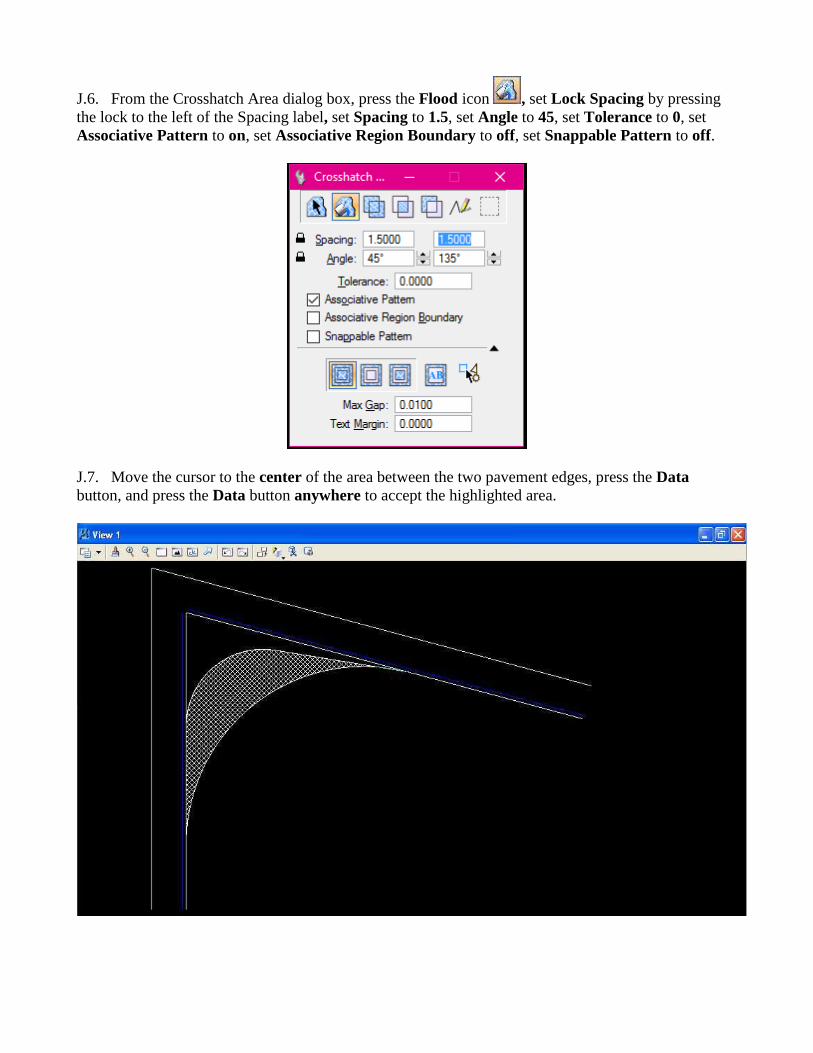
J.6. From the Crosshatch Area dialog box, press the Flood icon , set Lock Spacing by pressing
the lock to the left of the Spacing label, set Spacing to 1.5, set Angle to 45, set Tolerance to 0, set
Associative Pattern to on, set Associative Region Boundary to off, set Snappable Pattern to off.
J.7. Move the cursor to the center of the area between the two pavement edges, press the Data
button, and press the Data button anywhere to accept the highlighted area.
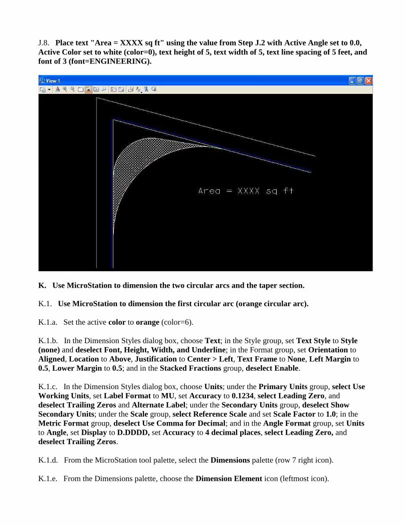
J.8. Place text "Area = XXXX sq ft" using the value from Step J.2 with Active Angle set to 0.0,
Active Color set to white (color=0), text height of 5, text width of 5, text line spacing of 5 feet, and
font of 3 (font=ENGINEERING).
K. Use MicroStation to dimension the two circular arcs and the taper section.
K.1. Use MicroStation to dimension the first circular arc (orange circular arc).
K.1.a. Set the active color to orange (color=6).
K.1.b. In the Dimension Styles dialog box, choose Text; in the Style group, set Text Style to Style
(none) and deselect Font, Height, Width, and Underline; in the Format group, set Orientation to
Aligned, Location to Above, Justification to Center > Left, Text Frame to None, Left Margin to
0.5, Lower Margin to 0.5; and in the Stacked Fractions group, deselect Enable.
K.1.c. In the Dimension Styles dialog box, choose Units; under the Primary Units group, select Use
Working Units, set Label Format to MU, set Accuracy to 0.1234, select Leading Zero, and
deselect Trailing Zeros and Alternate Label; under the Secondary Units group, deselect Show
Secondary Units; under the Scale group, select Reference Scale and set Scale Factor to 1.0; in the
Metric Format group, deselect Use Comma for Decimal; and in the Angle Format group, set Units
to Angle, set Display to D.DDDD, set Accuracy to 4 decimal places, select Leading Zero, and
deselect Trailing Zeros.
K.1.d. From the MicroStation tool palette, select the Dimensions palette (row 7 right icon).
K.1.e. From the Dimensions palette, choose the Dimension Element icon (leftmost icon).
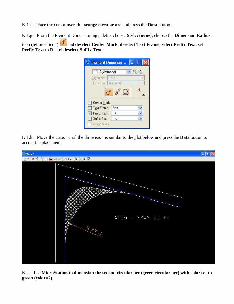
K.1.f. Place the cursor over the orange circular arc and press the Data button.
K.1.g. From the Element Dimensioning palette, choose Style: (none), choose the Dimension Radius
icon (leftmost icon) and deselect Center Mark, deselect Text Frame, select Prefix Text, set
Prefix Text to R, and deselect Suffix Text.
K.1.h. Move the cursor until the dimension is similar to the plot below and press the Data button to
accept the placement.
K.2. Use MicroStation to dimension the second circular arc (green circular arc) with color set to
green (color=2).
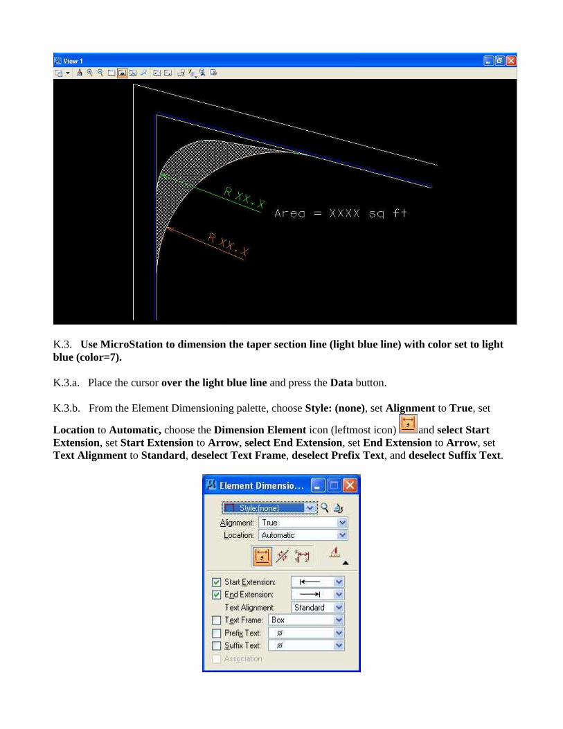
K.3. Use MicroStation to dimension the taper section line (light blue line) with color set to light
blue (color=7).
K.3.a. Place the cursor over the light blue line and press the Data button.
K.3.b. From the Element Dimensioning palette, choose Style: (none), set Alignment to True, set
Location to Automatic, choose the Dimension Element icon (leftmost icon) and select Start
Extension, set Start Extension to Arrow, select End Extension, set End Extension to Arrow, set
Text Alignment to Standard, deselect Text Frame, deselect Prefix Text, and deselect Suffix Text.
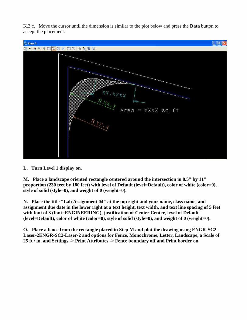
K.3.c. Move the cursor until the dimension is similar to the plot below and press the Data button to
accept the placement.
L. Turn Level 1 display on.
M. Place a landscape oriented rectangle centered around the intersection in 8.5" by 11"
proportion (230 feet by 180 feet) with level of Default (level=Default), color of white (color=0),
style of solid (style=0), and weight of 0 (weight=0).
N. Place the title "Lab Assignment 04" at the top right and your name, class name, and
assignment due date in the lower right at a text height, text width, and text line spacing of 5 feet
with font of 3 (font=ENGINEERING), justification of Center Center, level of Default
(level=Default), color of white (color=0), style of solid (style=0), and weight of 0 (weight=0).
O. Place a fence from the rectangle placed in Step M and plot the drawing using ENGR-SC2-
Laser-2ENGR-SC2-Laser-2 and options for Fence, Monochrome, Letter, Landscape, a Scale of
25 ft / in, and Settings -> Print Attributes -> Fence boundary off and Print border on.
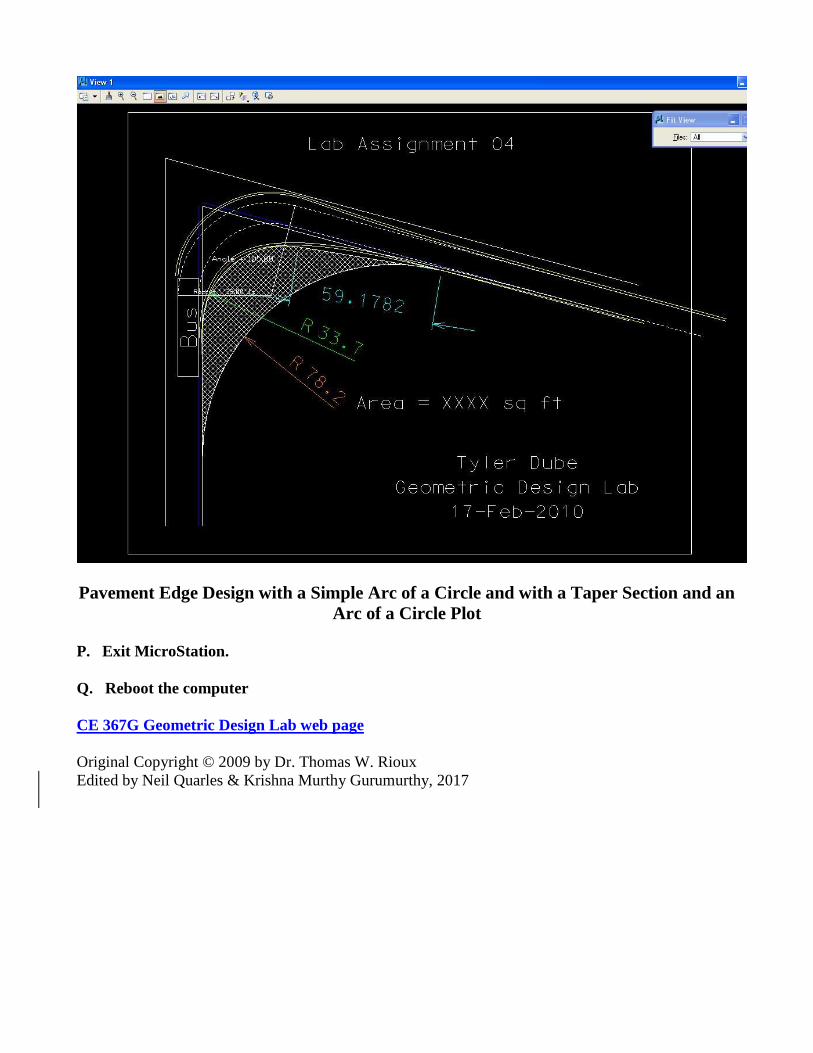
Pavement Edge Design with a Simple Arc of a Circle and with a Taper Section and an
Arc of a Circle Plot
P. Exit MicroStation.
Q. Reboot the computer
CE 367G Geometric Design Lab web page
Original Copyright © 2009 by Dr. Thomas W. Rioux
Edited by Neil Quarles & Krishna Murthy Gurumurthy, 2017