ce327-analysis and design software lab - indian institute …sghosh/ce327/matrix_anal_… · ·...
TRANSCRIPT
CE327-Analysis and Design Software Lab
SAP2000 Demonstration

• The following is a step-by-step procedure for analysis a two-dimensional truss structure using SAP 2000. The order of some of these steps is not critical; however, all step should be completed before execution of the analysis.
• The following tutorial will focus on determining the forces in each member of the truss shown below. Assume all members are pin connected.

Given problem:

When you start SAP 2000 Version 12 you should see the following interface window:
Step 1: Set Problem Dimensions - On the bottom on the interface window, set the desired units for the problem using the pull-down menu. In this example, the units are Newton and meter.
Units

Step 2: A)When you select new model on the menu, window will appear showing different templates such as , beam, 2D &3D trusses, 2D frames etc. For our problem we can define it by two ways,1)by directly taking given template for 2D truss 2) & by using grid only template.
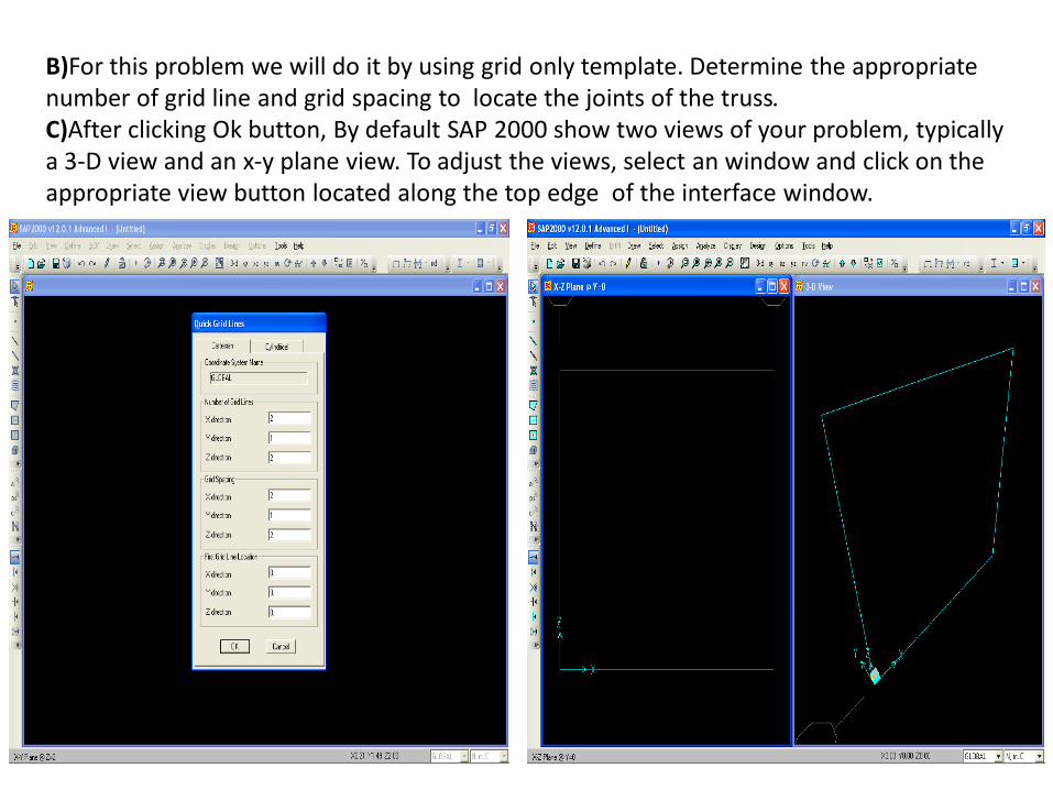
B)For this problem we will do it by using grid only template. Determine the appropriate number of grid line and grid spacing to locate the joints of the truss.C)After clicking Ok button, By default SAP 2000 show two views of your problem, typically a 3-D view and an x-y plane view. To adjust the views, select an window and click on the appropriate view button located along the top edge of the interface window.
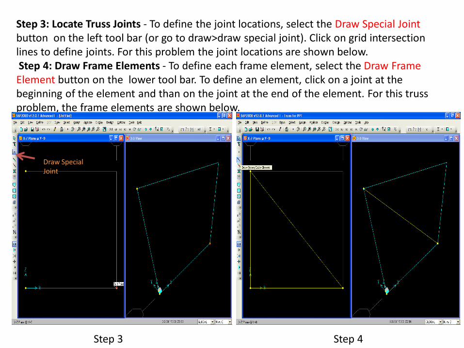
Step 3: Locate Truss Joints - To define the joint locations, select the Draw Special Joint button on the left tool bar (or go to draw>draw special joint). Click on grid intersection lines to define joints. For this problem the joint locations are shown below.Step 4: Draw Frame Elements - To define each frame element, select the Draw Frame Element button on the lower tool bar. To define an element, click on a joint at the beginning of the element and than on the joint at the end of the element. For this truss problem, the frame elements are shown below.
Draw Special Joint
Step 3 Step 4
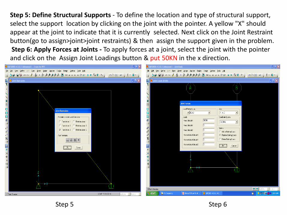
Step 5: Define Structural Supports - To define the location and type of structural support, select the support location by clicking on the joint with the pointer. A yellow "X" should appear at the joint to indicate that it is currently selected. Next click on the Joint Restraint button(go to assign>joint>joint restraints) & then assign the support given in the problem.Step 6: Apply Forces at Joints - To apply forces at a joint, select the joint with the pointer and click on the Assign Joint Loadings button & put 50KN in the x direction.
Step 5 Step 6

Step 7: Release Internal Moments at Joints - SAP 2000 assumes that all structures are frames.Therefore,to analyze a truss structure we should convert each joint from a fixed connection to a pin connection. To ensure that every joint in the structure is pin connected, select all the members by clicking the Select All button on the left tool bar. Next click on Assign menu >Frame > Releases /partial fixity and then Frame Releases window will appear.
Assigning frame
releases

Step8:Define & Assign Material Properties –A)To define the properties of a material , select the Define menu located along the top the SAP 2000 interface window and then click on Materials. The Define Materials window will appear .On this menu you can change the properties of materials. In this example, select add new material and change the properties as shown. And go to switch to advanced property display.

B)Change the value in the Weight per unit Volume & mass per unit volume input field to zero. For this example problem, put the given values of Modulus of elasticity, Poisson's ratio & yield stress(250Mpa). Now we have a material named STEEL ,change the nonlinear material data as shown in figure. Then select all>assign>material property overwrites>STEEL.

Step 9: Define Frame Sections - To define the cross-section properties of a structural element click on the Define menu located along the top the SAP 2000 interface window and then click on Frame Sections. We can Define sections in 3 different ways ,a)Define>Section properties>Frame sections>Import new property>I/Wide flange>sections.prob)Define>Section properties>Frame sections>Add new property>Frame section property type(other)>general>fill section properties(Area, Moment of inertia. etc)>Enter depth & Widthc)Define>Section properties>Frame sections>Add new property>Frame section property type(other)>general>Section designerFor this problem we will use option b) to define sections.Step10:Assign Frame sections- To assign the frame section , first select all member then go to Assign>Frame>Frame sections>Frame properties and then click ok.
Define sections
Define C/S Area
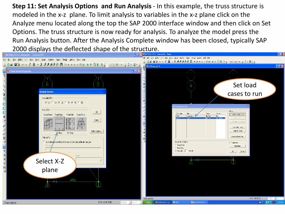
Step 11: Set Analysis Options and Run Analysis - In this example, the truss structure is modeled in the x-z plane. To limit analysis to variables in the x-z plane click on the Analyze menu located along the top the SAP 2000 interface window and then click on Set Options. The truss structure is now ready for analysis. To analyze the model press the Run Analysis button. After the Analysis Complete window has been closed, typically SAP 2000 displays the deflected shape of the structure.
Select X-Z plane
Set load cases to run
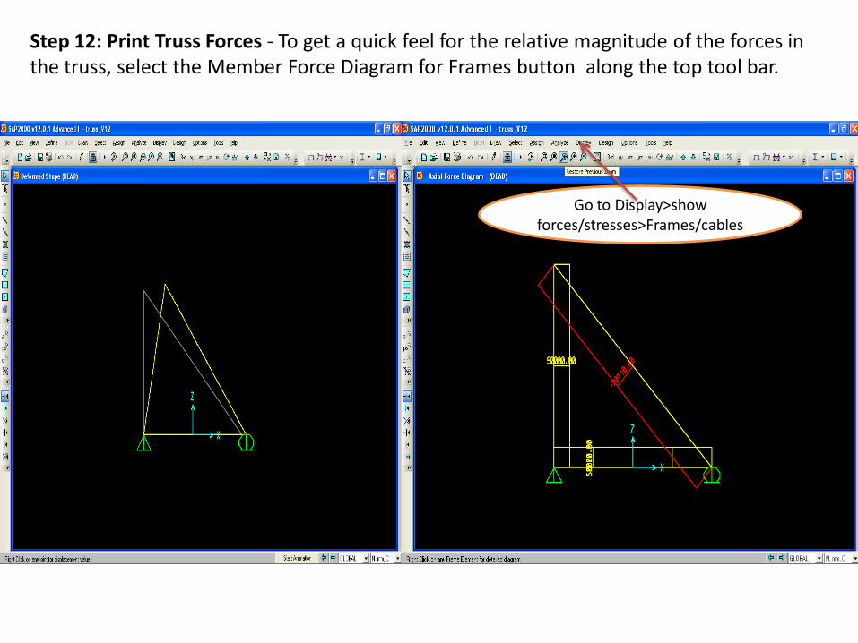
Step 12: Print Truss Forces - To get a quick feel for the relative magnitude of the forces in the truss, select the Member Force Diagram for Frames button along the top tool bar.
Go to Display>show forces/stresses>Frames/cables
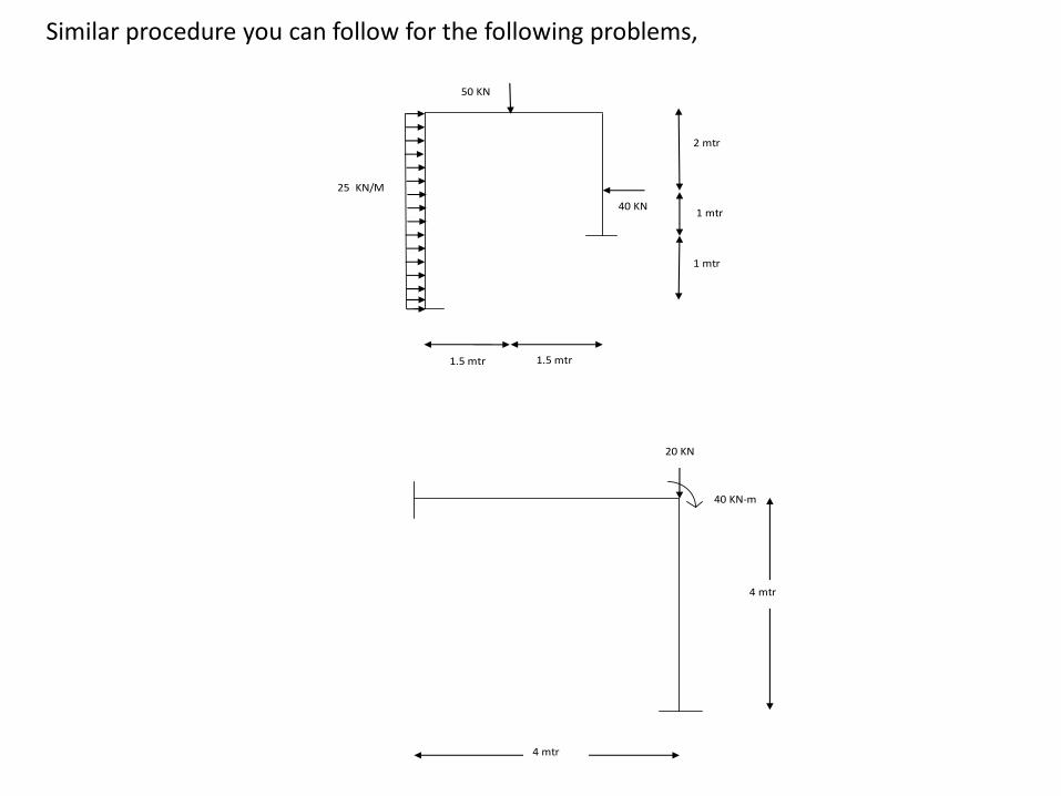
Similar procedure you can follow for the following problems,
40 KN
2
50 KN
2
25 KN/M
2
1.5 mtr
2
1.5 mtr
2
2 mtr
2
1 mtr
2
1 mtr
2
20 KN
2
40 KN-m
2
4 mtr
2
4 mtr