ce test report 300 328...1 bl600-sa bl620-sa chip acx at5020-e3r0hbant/lf na 0.00 2 bl600-sc...
TRANSCRIPT

Report No.: ER330802-02 Page : 1 of 103
Report Version: Rev. 01
CE Test Report
Equipment : BL600 Series Bluetooth Low Energy Module
Model No. : BL600-SA, BL600-SC, BL600-ST
Multiple Listing : Refer to item 1.1.1 for more details
Brand Name : Laird Technologies
Applicant : Laird Technologies
Address : 11160 Thompson Ave. / Lenexa, Kansas / 66219 / USA
Standard : EN 300 328 V1.9.1 (2015-02)
Received Date : Jan. 30, 2016
Tested Date : Jan. 30 ~ May 23, 2016
We, International Certification Corp., would like to declare that the tested sample has been evaluated and in compliance with the requirement of the above standards. The test results contained in this report refer exclusively to the product. It may be duplicated completely for legal use with the approval of the applicant. It shall not be reproduced except in full without the written approval of our laboratory. Approved & Reviewed by:
Gary Chang / Manager Ty: XXX
Report No.: ER330802-02 Page : 2 of 103
Report Version: Rev. 01
Table of Contents 1 GENERAL DESCRIPTION .................................................................................................................... 5
1.1 Information .............................................................................................................................................. 5 1.2 Local Support Equipment List ................................................................................................................ 7 1.3 Test Setup Chart .................................................................................................................................... 8 1.4 Test Equipment List and Calibration Data .............................................................................................. 9 1.5 Testing Applied Standards ................................................................................................................... 10 1.6 Measurement Uncertainty .................................................................................................................... 10
2 TEST CONFIGURATION ..................................................................................................................... 11
2.1 Testing Condition ................................................................................................................................. 11 2.2 The Worst Test Modes and Channel Details ....................................................................................... 11
3 TRANSMITTER TEST RESULTS ........................................................................................................ 12
3.1 RF Output Power .................................................................................................................................. 12 3.2 Power Spectral Density ........................................................................................................................ 17 3.3 Occupied Channel Bandwidth .............................................................................................................. 20 3.4 Transmitter Unwanted Emissions in the Out-Of-Band Domain ............................................................ 22 3.5 Transmitter Unwanted Emissions in the Spurious Domain .................................................................. 31
4 RECEIVER TEST RESULTS ............................................................................................................... 65
4.1 Receiver Spurious Emissions ............................................................................................................... 65
5 PHOTOGRAPHS OF THE TEST CONFIGURATION ......................................................................... 99
6 TEST LABORATORY INFORMATION ............................................................................................. 103

Report No.: ER330802-02 Page : 3 of 103
Report Version: Rev. 01
Release Record
Report No. Version Description Issued Date
ER330802-02 Rev. 01 Initial issue Jun. 14, 2016

Report No.: ER330802-02 Page : 4 of 103
Report Version: Rev. 01
Summary of Test Results
Ref. Std. Clause
Test Items Measured Result
4.3.2.2 RF Output Power 7.23 dBm Pass
4.3.2.3 Power Spectral Density Meet the requirement of limit. Pass
4.3.2.4 Duty Cycle, Tx-sequence, Tx-gap Only for non-adaptive equipment
N/A
4.3.2.5 Medium Utilisation (MU) factor Only for non-adaptive equipment
N/A
4.3.2.6 Adaptivity The RF Output power is less than 10 dBm e.i.r.p. This item is not applicable.
N/A
4.3.2.7 Occupied Channel Bandwidth Meet the requirement of limit. Pass
4.3.2.8 Transmitter unwanted emissions in the out of band domain
Meet the requirement of limit. Pass
4.3.2.9 Transmitter unwanted emissions in the spurious domain
Meet the requirement of limit. Pass
4.3.2.10 Receiver spurious emissions Meet the requirement of limit. Pass
4.3.2.11 Receiver Blocking The RF Output power is less than 10 dBm e.i.r.p. This item is not applicable
N/A
4.3.2.12 Geo-location Capability The device has no this capability.
N/A

Report No.: ER330802-02 Page : 5 of 103
Report Version: Rev. 01
1 General Description
1.1 Information
1.1.1 Product Details
The following models are provided to this EUT.
Brand Name Model Name Product Name Description
Laird Technologies
BL600-SA BL620-SA
BL600 Series Bluetooth Low Energy Module
Integrated antenna onboard
BL600-SC BL620-SC No integrated antenna, only IPEX MHF4 RF connector for external antenna
BL600-ST BL620-ST No integrated antenna or RF IPEX connector – external antenna connection via RF Trace Pins
BL600-SA & BL620-SA only for marketing purpose. BL600-SC & BL620-SC only for marketing purpose. BL600-ST & BL620-ST only for marketing purpose.
1.1.2 Specification of the Equipment under Test (EUT)
RF General Information
Frequency Range (MHz)
Bluetooth Mode
Ch. Frequency (MHz)
Channel Number Data Rate
2400-2483.5 V4.0 LE 2402-2480 0-39 [40] 1 Mbps
Note 1: Bluetooth LE (Low energy) uses GFSK modulation.
1.1.3 Antenna Details
No. EUT Model Ant. Type Ant. Brand/Model Connector Gain (dBi)
1 BL600-SA BL620-SA chip ACX AT5020-E3R0HBANT/LF
NA 0.00
2 BL600-SC BL620-SC PCB Dipole MAG. LAYERS SCIENTIFIC-TECHNICS CO., LTD PCA-4606-2G4C1-A33-CY
IPEX 4 Compatible
2.21
3 BL600-SC BL620-SC Dipole MAG. LAYERS SCIENTIFIC-TECHNICS CO., LTD EDA-8709-2G4C1-B27-CY
IPEX Compatible(MHF4)
2.00
4 BL600-ST BL620-ST Dipole MAG. LAYERS SCIENTIFIC-TECHNICS CO., LTD EDA-8709-2G4R2-A40-CY
SMA Male Reverse
2.00

Report No.: ER330802-02 Page : 6 of 103
Report Version: Rev. 01
1.1.4 EUT Operational Condition
Power Supply Type 3.3 / 1.8 Vdc from host
Operational Climatic Tnom (20°C) Tmax (75°C) Tmin (-25°C)
1.1.5 Accessories
N/A
1.1.6 Channel List
Channel No. Frequency (MHz) Channel No. Frequency (MHz)
37 2402 18 2442
0 2404 19 2444
1 2406 20 2446
2 2408 21 2448
3 2410 22 2450
4 2412 23 2452
5 2414 24 2454
6 2416 25 2456
7 2418 26 2458
8 2420 27 2460
9 2422 28 2462
10 2424 29 2464
38 2426 30 2466
11 2428 31 2468
12 2430 32 2470
13 2432 33 2472
14 2434 34 2474
15 2436 35 2476
16 2438 36 2478
17 2440 39 2480
Report No.: ER330802-02 Page : 7 of 103
Report Version: Rev. 01
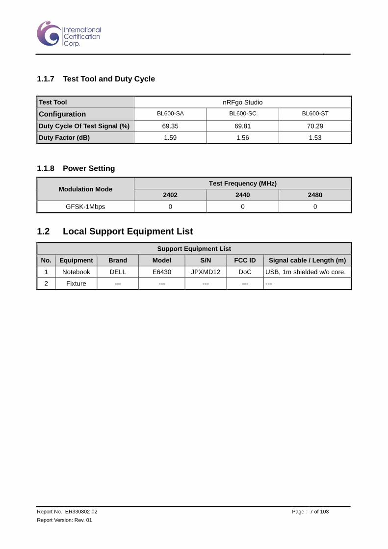
1.1.7 Test Tool and Duty Cycle
Test Tool nRFgo Studio
Configuration BL600-SA BL600-SC BL600-ST
Duty Cycle Of Test Signal (%) 69.35 69.81 70.29
Duty Factor (dB) 1.59 1.56 1.53
1.1.8 Power Setting
Modulation Mode Test Frequency (MHz)
2402 2440 2480
GFSK-1Mbps 0 0 0
1.2 Local Support Equipment List
Support Equipment List
No. Equipment Brand Model S/N FCC ID Signal cable / Length (m)
1 Notebook DELL E6430 JPXMD12 DoC USB, 1m shielded w/o core.
2 Fixture --- --- --- --- ---

Report No.: ER330802-02 Page : 8 of 103
Report Version: Rev. 01
1.3 Test Setup Chart
Test Setup Diagram

Report No.: ER330802-02 Page : 9 of 103
Report Version: Rev. 01
1.4 Test Equipment List and Calibration Data
Test Item Radiated Emissions
Test Site Fully-anechoic chamber 2 / (05CH02-WS)
Instrument Manufacturer Model No. Serial No. Calibration Date Calibration Until
Spectrum Analyzer Agilent N9010A MY52221474 Sep. 08, 2015 Sep. 07, 2016
Bilog Antenna 30-1000MHz
SCHWARZBECK VULB9168 9168-563 Dec. 29, 2015 Dec. 28, 2016
Horn Antenna 1G-18G
SCHWARZBECK BBHA 9120 D 9120D-1205 Jan. 08, 2016 Jan. 07, 2017
Horn Antenna 18G-40G
SCHWARZBECK BBHA 9170 BBHA 9170508 Jan. 04, 2016 Jan. 03, 2017
Preamplifier Agilent 83017A MY53270013 Jan. 27, 2016 Jan. 26, 2017
Preamplifier 30-1000MHz
EMC EMC02325 980188 Dec. 10, 2015 Dec. 09, 2016
Preamplifier EMC EMC184045B 980192 Sep. 01, 2015 Aug. 31, 2016
RF cable-1M HUBER+SUHNER SUCOFLEX104 MY22622/4 Dec. 04, 2015 Dec. 03, 2016
RF cable-1M HUBER+SUHNER SUCOFLEX104 MY22623/4 Dec. 04, 2015 Dec. 03, 2016
RF cable-3M HUBER+SUHNER SUCOFLEX104 MY22621/4 Dec. 04, 2015 Dec. 03, 2016
RF cable-4M HUBER+SUHNER SUCOFLEX104 MY22579/4 Dec. 04, 2015 Dec. 03, 2016
LF cable-0.8M EMC EMC8D-NM-NM-800 EMC8D-NM-NM-800-002 Dec. 04, 2015 Dec. 03, 2016
LF cable-3M EMC EMC8D-NM-NM-3000 131102 Dec. 04, 2015 Dec. 03, 2016
LF cable-10M EMC EMC8D-NM-NM-10000 131101 Dec. 04, 2015 Dec. 03, 2016
Measurement Software
AUDIX e3 6.120210g NA NA
Note: Calibration Interval of instruments listed above is one year.
Test Item RF Conducted
Test Site (TH01-WS)
Instrument Manufacturer Model No. Serial No. Calibration Date Calibration Until
Spectrum Analyzer ROHDE&SCHWARZ FSV40 101486 Oct. 14, 2015 Oct. 13, 2016
TEMP&HUMIDITY CHAMBER
GIANT FORCE GCT-225-40-SP-SD MAF1212-002 Nov. 27, 2015 Nov. 26, 2016
Power Meter Anritsu ML2495A 1241002 Sep. 21, 2015 Sep. 20, 2016
Power Sensor Anritsu MA2411B 1207366 Sep. 21, 2015 Sep. 20, 2016
DC POWER SOURCE
GW INSTEK GPC-3060D EM884797 Oct. 20, 2015 Oct. 19, 2016
Measurement Software
Sporton Sporton_1 1.3.30 NA NA
Measurement Software
Agilent EN RF test 1.1501125 NA NA
Note: Calibration Interval of instruments listed above is one year.
Report No.: ER330802-02 Page : 10 of 103
Report Version: Rev. 01
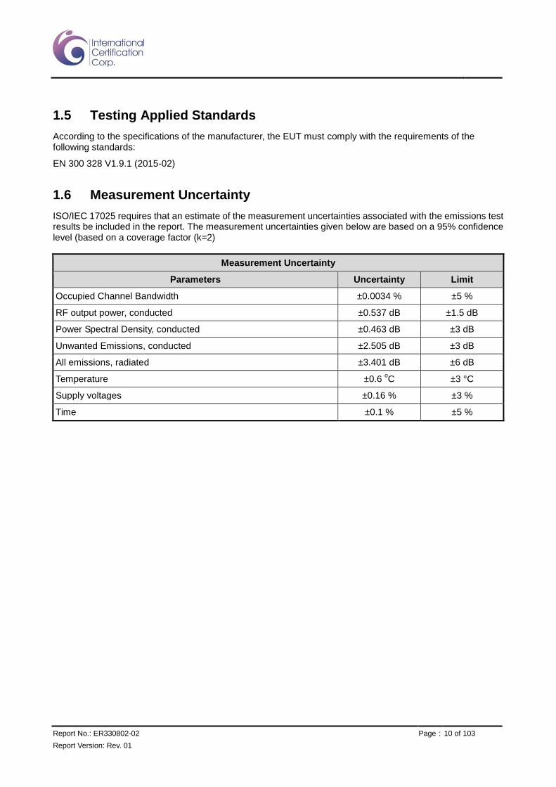
1.5 Testing Applied Standards
According to the specifications of the manufacturer, the EUT must comply with the requirements of the following standards:
EN 300 328 V1.9.1 (2015-02)
1.6 Measurement Uncertainty
ISO/IEC 17025 requires that an estimate of the measurement uncertainties associated with the emissions test results be included in the report. The measurement uncertainties given below are based on a 95% confidence level (based on a coverage factor (k=2)
Measurement Uncertainty
Parameters Uncertainty Limit
Occupied Channel Bandwidth ±0.0034 % ±5 %
RF output power, conducted ±0.537 dB ±1.5 dB
Power Spectral Density, conducted ±0.463 dB ±3 dB
Unwanted Emissions, conducted ±2.505 dB ±3 dB
All emissions, radiated ±3.401 dB ±6 dB
Temperature ±0.6 oC ±3 °C
Supply voltages ±0.16 % ±3 %
Time ±0.1 % ±5 %

Report No.: ER330802-02 Page : 11 of 103
Report Version: Rev. 01
2 Test Configuration
2.1 Testing Condition
Test Item Test Site Ambient Condition Tested By
RF Conducted TH01-WS 23°C / 63% Nic Guan
Radiated Emission 05CH02-WS 19°C / 70% Ryan Lee
2.2 The Worst Test Modes and Channel Details
Test item Modulation
Mode Test Frequency
(MHz) Data Rate Test Configuration
RF Output Power GFSK 2402 / 2440 / 2480 1 Mbps 1, 2, 3, 4 / 3.3 & 1.8Vdc
Power Spectral Density
Occupied Channel Bandwidth GFSK 2402 / 2480 1 Mbps 1, 2, 3, 4 / 3.3 Vdc
Transmitter unwanted emissions in the out of band domain
GFSK 2402 / 2480 1 Mbps 1, 2, 3, 4 / 3.3 & 1.8Vdc
Transmitter Spurious Emissions GFSK 2402 / 2480 1 Mbps 1, 2, 3, 4 / 3.3 Vdc
Receiver Spurious Emissions
NOTE:
1. The EUT was pretested with 3 orientations placed on the table for the radiated emission measurement – X, Y, and Z-plane. The X-plane for BT600-SA and Z-plane for BT 600-SC / -STresult was found as the worst case and was
shown in this report.
2. The test configuration listed as follows:
Configuration 1: BL600-SA with Chip antenna, X-plane
Configuration 2: BL600-SC with PCB Dipole antenna., Z-plane
Configuration 3: BL600-SC with Dipole antenna. , Z-plane
Configuration 4: BL600-ST with Dipole antenna, Z-plane

Report No.: ER330802-02 Page : 12 of 103
Report Version: Rev. 01
3 Transmitter Test Results
3.1 RF Output Power
3.1.1 Limit of RF Output Power
The maximum RF output power shall be equal to or less than 20 dBm
3.1.2 Test Procedures
Reference to clause 5.3.2.2 of ETSI EN 300 328 V1.9.1 (2015-02).
3.1.3 Test Setup

Report No.: ER330802-02 Page : 13 of 103
Report Version: Rev. 01
3.1.4 Test Result of RF Output Power
For 3.3 Vdc from host
Test Configuration 1 / Radiated measurement
RF Output Power (dBm)
Condition Freq. (MHz) EIRP Power Limit (dBm) Results
TnomVnom 2402 -0.98 20 Pass
TminVnom 2402 0.57 20 Pass
TmaxVnom 2402 -2.03 20 Pass
TnomVnom 2440 0.72 20 Pass
TminVnom 2440 2.25 20 Pass
TmaxVnom 2440 -0.36 20 Pass
TnomVnom 2480 -0.02 20 Pass
TminVnom 2480 1.49 20 Pass
TmaxVnom 2480 -1.08 20 Pass
Test Configuration 2 / Conducted measurement
RF Output Power (dBm)
Condition Freq. (MHz) EIRP Power Limit (dBm) Results
TnomVnom 2402 5.85 20 Pass
TminVnom 2402 6.96 20 Pass
TmaxVnom 2402 4.18 20 Pass
TnomVnom 2440 5.95 20 Pass
TminVnom 2440 7.08 20 Pass
TmaxVnom 2440 4.17 20 Pass
TnomVnom 2480 5.66 20 Pass
TminVnom 2480 6.82 20 Pass
TmaxVnom 2480 4.05 20 Pass

Report No.: ER330802-02 Page : 14 of 103
Report Version: Rev. 01
Test Configuration 3 / Conducted measurement
RF Output Power (dBm)
Condition Freq. (MHz) EIRP Power Limit (dBm) Results
TnomVnom 2402 5.64 20 Pass
TminVnom 2402 6.75 20 Pass
TmaxVnom 2402 3.97 20 Pass
TnomVnom 2440 5.74 20 Pass
TminVnom 2440 6.87 20 Pass
TmaxVnom 2440 3.96 20 Pass
TnomVnom 2480 5.45 20 Pass
TminVnom 2480 6.61 20 Pass
TmaxVnom 2480 3.84 20 Pass
Test Configuration 4 / Conducted measurement
RF Output Power (dBm)
Condition Freq. (MHz) EIRP Power Limit (dBm) Results
TnomVnom 2402 6.67 20 Pass
TminVnom 2402 6.06 20 Pass
TmaxVnom 2402 3.56 20 Pass
TnomVnom 2440 6.89 20 Pass
TminVnom 2440 5.97 20 Pass
TmaxVnom 2440 3.63 20 Pass
TnomVnom 2480 7.23 20 Pass
TminVnom 2480 6.02 20 Pass
TmaxVnom 2480 3.59 20 Pass
Report No.: ER330802-02 Page : 15 of 103
Report Version: Rev. 01
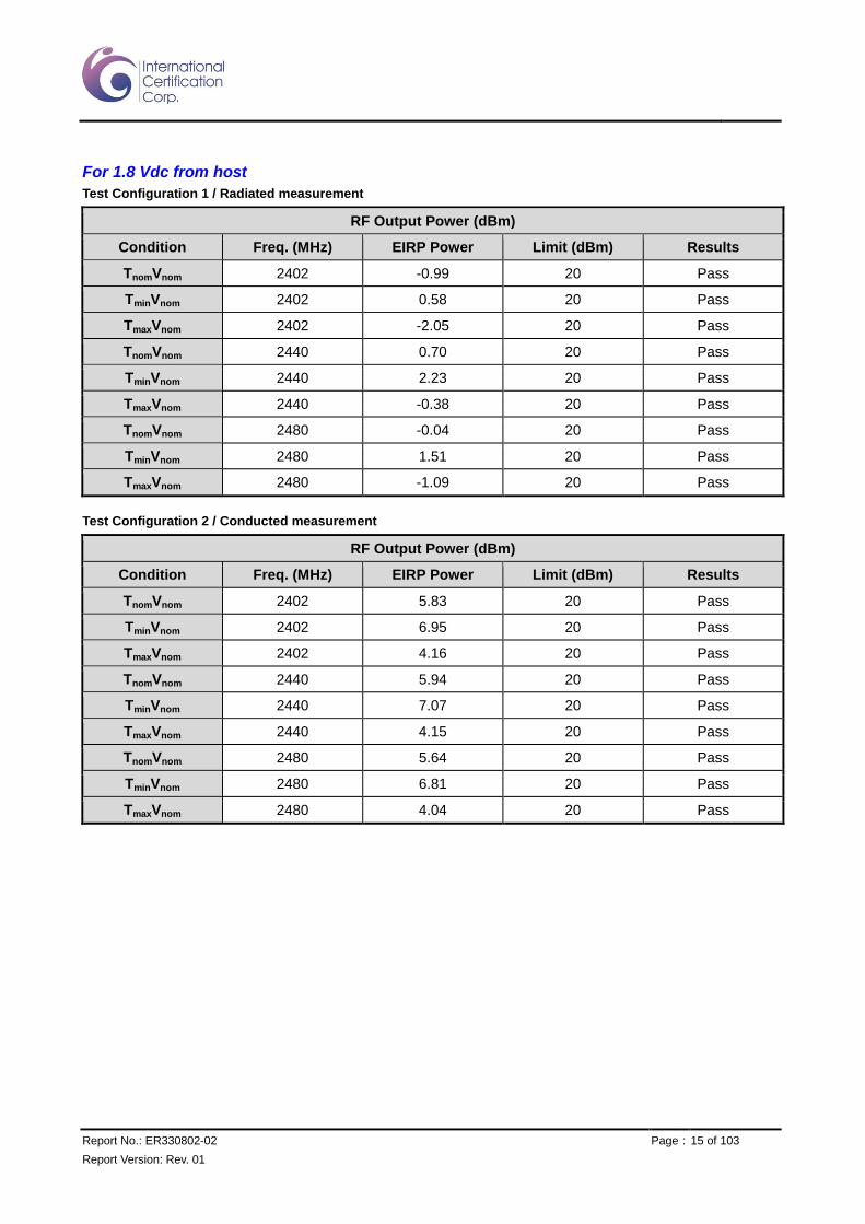
For 1.8 Vdc from host
Test Configuration 1 / Radiated measurement
RF Output Power (dBm)
Condition Freq. (MHz) EIRP Power Limit (dBm) Results
TnomVnom 2402 -0.99 20 Pass
TminVnom 2402 0.58 20 Pass
TmaxVnom 2402 -2.05 20 Pass
TnomVnom 2440 0.70 20 Pass
TminVnom 2440 2.23 20 Pass
TmaxVnom 2440 -0.38 20 Pass
TnomVnom 2480 -0.04 20 Pass
TminVnom 2480 1.51 20 Pass
TmaxVnom 2480 -1.09 20 Pass
Test Configuration 2 / Conducted measurement
RF Output Power (dBm)
Condition Freq. (MHz) EIRP Power Limit (dBm) Results
TnomVnom 2402 5.83 20 Pass
TminVnom 2402 6.95 20 Pass
TmaxVnom 2402 4.16 20 Pass
TnomVnom 2440 5.94 20 Pass
TminVnom 2440 7.07 20 Pass
TmaxVnom 2440 4.15 20 Pass
TnomVnom 2480 5.64 20 Pass
TminVnom 2480 6.81 20 Pass
TmaxVnom 2480 4.04 20 Pass
Report No.: ER330802-02 Page : 16 of 103
Report Version: Rev. 01
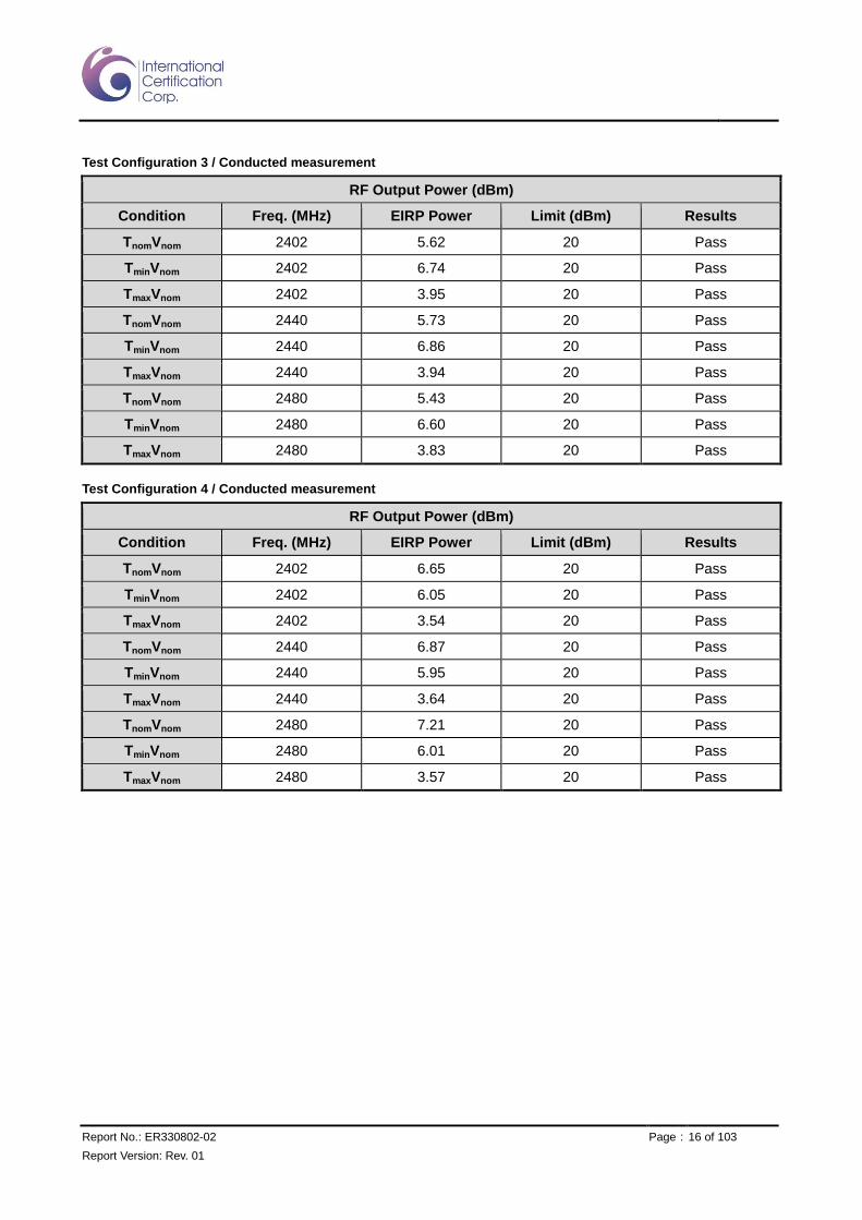
Test Configuration 3 / Conducted measurement
RF Output Power (dBm)
Condition Freq. (MHz) EIRP Power Limit (dBm) Results
TnomVnom 2402 5.62 20 Pass
TminVnom 2402 6.74 20 Pass
TmaxVnom 2402 3.95 20 Pass
TnomVnom 2440 5.73 20 Pass
TminVnom 2440 6.86 20 Pass
TmaxVnom 2440 3.94 20 Pass
TnomVnom 2480 5.43 20 Pass
TminVnom 2480 6.60 20 Pass
TmaxVnom 2480 3.83 20 Pass
Test Configuration 4 / Conducted measurement
RF Output Power (dBm)
Condition Freq. (MHz) EIRP Power Limit (dBm) Results
TnomVnom 2402 6.65 20 Pass
TminVnom 2402 6.05 20 Pass
TmaxVnom 2402 3.54 20 Pass
TnomVnom 2440 6.87 20 Pass
TminVnom 2440 5.95 20 Pass
TmaxVnom 2440 3.64 20 Pass
TnomVnom 2480 7.21 20 Pass
TminVnom 2480 6.01 20 Pass
TmaxVnom 2480 3.57 20 Pass

Report No.: ER330802-02 Page : 17 of 103
Report Version: Rev. 01
3.2 Power Spectral Density
3.2.1 Limit of Power Spectral Density
For equipment using wide band modulations other than FHSS (e.g. DSSS, OFDM, etc.), the maximum Power Spectral Density is limited to 10 dBm per MHz.
3.2.2 Test Procedures
Reference to clause 5.3.3.2 of ETSI EN 300 328 V1.9.1 (2015-02).
3.2.3 Test Setup
Report No.: ER330802-02 Page : 18 of 103
Report Version: Rev. 01
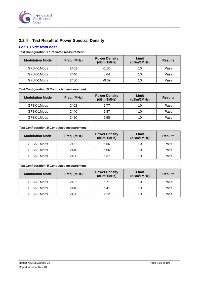
3.2.4 Test Result of Power Spectral Density
For 3.3 Vdc from host
Test Configuration 1 / Radiated measurement
Modulation Mode Freq. (MHz) Power Density (dBm/1MHz)
Limit (dBm/1MHz)
Results
GFSK-1Mbps 2402 -1.06 10 Pass
GFSK-1Mbps 2440 0.64 10 Pass
GFSK-1Mbps 2480 -0.09 10 Pass
Test Configuration 2/ Conducted measurement
Modulation Mode Freq. (MHz) Power Density (dBm/1MHz)
Limit (dBm/1MHz)
Results
GFSK-1Mbps 2402 5.77 10 Pass
GFSK-1Mbps 2440 5.87 10 Pass
GFSK-1Mbps 2480 5.58 10 Pass
Test Configuration 3/ Conducted measurement
Modulation Mode Freq. (MHz) Power Density (dBm/1MHz)
Limit (dBm/1MHz)
Results
GFSK-1Mbps 2402 5.56 10 Pass
GFSK-1Mbps 2440 5.66 10 Pass
GFSK-1Mbps 2480 5.37 10 Pass
Test Configuration 4/ Conducted measurement
Modulation Mode Freq. (MHz) Power Density (dBm/1MHz)
Limit (dBm/1MHz)
Results
GFSK-1Mbps 2402 6.71 10 Pass
GFSK-1Mbps 2440 6.41 10 Pass
GFSK-1Mbps 2480 7.12 10 Pass

Report No.: ER330802-02 Page : 19 of 103
Report Version: Rev. 01
For 1.8 Vdc from host
Test Configuration 1 / Radiated measurement
Modulation Mode Freq. (MHz) Power Density (dBm/1MHz)
Limit (dBm/1MHz)
Results
GFSK-1Mbps 2402 -1.06 10 Pass
GFSK-1Mbps 2440 0.64 10 Pass
GFSK-1Mbps 2480 -0.09 10 Pass
Test Configuration 2/ Conducted measurement
Modulation Mode Freq. (MHz) Power Density (dBm/1MHz)
Limit (dBm/1MHz)
Results
GFSK-1Mbps 2402 5.74 10 Pass
GFSK-1Mbps 2440 5.85 10 Pass
GFSK-1Mbps 2480 5.53 10 Pass
Test Configuration 3/ Conducted measurement
Modulation Mode Freq. (MHz) Power Density (dBm/1MHz)
Limit (dBm/1MHz)
Results
GFSK-1Mbps 2402 5.53 10 Pass
GFSK-1Mbps 2440 5.64 10 Pass
GFSK-1Mbps 2480 5.32 10 Pass
Test Configuration 4/ Conducted measurement
Modulation Mode Freq. (MHz) Power Density (dBm/1MHz)
Limit (dBm/1MHz)
Results
GFSK-1Mbps 2402 6.70 10 Pass
GFSK-1Mbps 2440 6.39 10 Pass
GFSK-1Mbps 2480 7.10 10 Pass
Report No.: ER330802-02 Page : 20 of 103
Report Version: Rev. 01
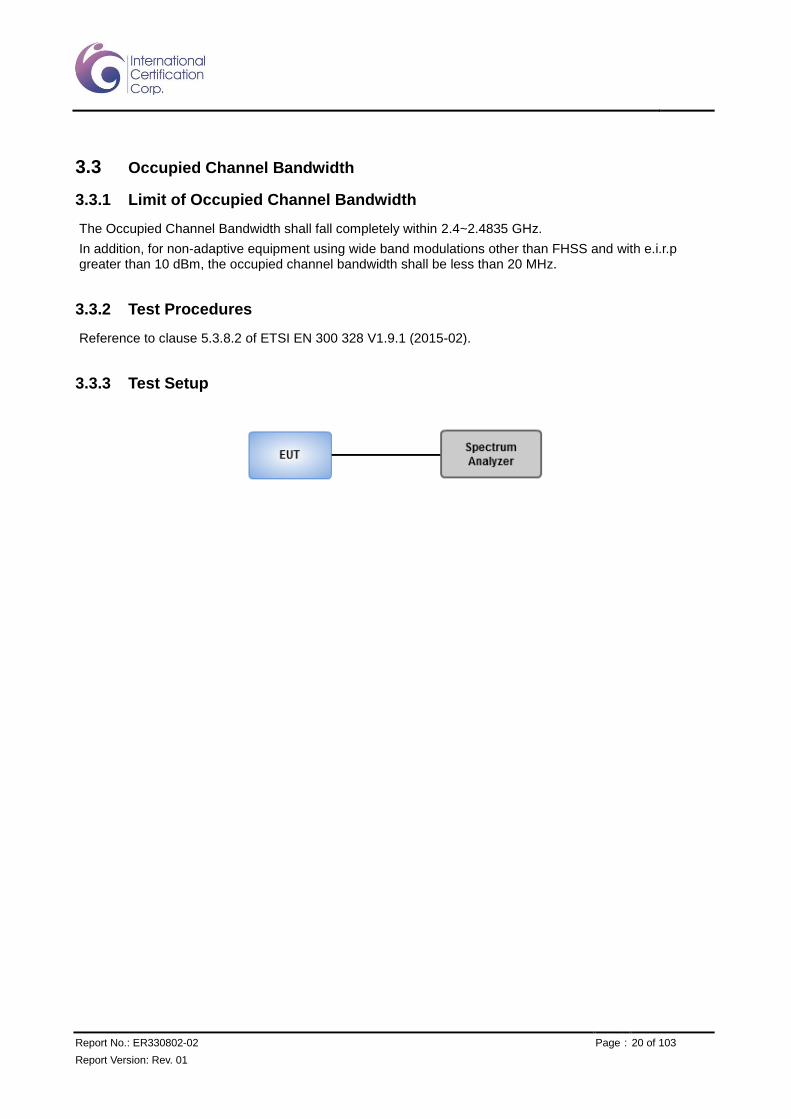
3.3 Occupied Channel Bandwidth
3.3.1 Limit of Occupied Channel Bandwidth
The Occupied Channel Bandwidth shall fall completely within 2.4~2.4835 GHz.
In addition, for non-adaptive equipment using wide band modulations other than FHSS and with e.i.r.p greater than 10 dBm, the occupied channel bandwidth shall be less than 20 MHz.
3.3.2 Test Procedures
Reference to clause 5.3.8.2 of ETSI EN 300 328 V1.9.1 (2015-02).
3.3.3 Test Setup

Report No.: ER330802-02 Page : 21 of 103
Report Version: Rev. 01
3.3.4 Test Result of Occupied Channel Bandwidth
Test Configuration 1
Modulation Mode
Frequency (MHz)
99% Bandwidth (MHz)
FL at 99% BW (MHz)
FH at 99% BW (MHz)
Limit FL / FH
(MHz)
GFSK-1Mbps 2402 1.02 2401.52 2402.54 2400.0
GFSK-1Mbps 2480 1.03 2479.51 2480.55 2483.5
Test Configuration 2
Modulation Mode
Frequency (MHz)
99% Bandwidth (MHz)
FL at 99% BW (MHz)
FH at 99% BW (MHz)
Limit FL / FH
(MHz)
GFSK-1Mbps 2402 1.02 2401.52 2402.54 2400.0
GFSK-1Mbps 2480 1.02 2479.51 2480.54 2483.5
Test Configuration 3
Modulation Mode
Frequency (MHz)
99% Bandwidth (MHz)
FL at 99% BW (MHz)
FH at 99% BW (MHz)
Limit FL / FH
(MHz)
GFSK-1Mbps 2402 1.02 2401.52 2402.54 2400.0
GFSK-1Mbps 2480 1.02 2479.51 2480.54 2483.5
Test Configuration 4
Modulation Mode
Frequency (MHz)
99% Bandwidth (MHz)
FL at 99% BW (MHz)
FH at 99% BW (MHz)
Limit FL / FH
(MHz)
GFSK-1Mbps 2402 1.03 2401.50 2402.53 2400.0
GFSK-1Mbps 2480 1.08 2479.47 2480.56 2483.5

Report No.: ER330802-02 Page : 22 of 103
Report Version: Rev. 01
3.4 Transmitter Unwanted Emissions in the Out-Of-Band Domain
3.4.1 Limit of Transmitter Unwanted Emissions in the Out-Of-Band Domain
3.4.2 Test Procedures
Reference to clause 5.3.9.2 of ETSI EN 300 328 V1.9.1 (2015-02).
3.4.3 Test Setup

Report No.: ER330802-02 Page : 23 of 103
Report Version: Rev. 01
3.4.4 Test Result of Transmitter Unwanted Emissions in the Out-Of-Band Domain
For 3.3 Vdc from host
Test Configuration 1
Condition Modulation
Mode Freq. (MHz)
OOB Freq. (MHz)
OOB Emissions
(dBm) Limit (dBm)
TnomVnom GFSK-1Mbps 2402 2399.50 -42.69 -10
TnomVnom GFSK-1Mbps 2402 2398.48 -48.17 -20
TnomVnom GFSK-1Mbps 2480 2484.00 -47.23 -10
TnomVnom GFSK-1Mbps 2480 2485.03 -47.79 -20
Low Band Up Band

Report No.: ER330802-02 Page : 24 of 103
Report Version: Rev. 01
Test Configuration 2
Condition Modulation
Mode Freq. (MHz)
OOB Freq. (MHz)
OOB Emissions
(dBm) Limit (dBm)
TnomVnom GFSK-1Mbps 2402 2399.50 -41.56 -10
TnomVnom GFSK-1Mbps 2402 2398.48 -50.29 -20
TnomVnom GFSK-1Mbps 2480 2484.00 -50.70 -10
TnomVnom GFSK-1Mbps 2480 2485.04 -52.61 -20
Low Band Up Band

Report No.: ER330802-02 Page : 25 of 103
Report Version: Rev. 01
Test Configuration 3
Condition Modulation
Mode Freq. (MHz)
OOB Freq. (MHz)
OOB Emissions
(dBm) Limit (dBm)
TnomVnom GFSK-1Mbps 2402 2399.50 -41.80 -10
TnomVnom GFSK-1Mbps 2402 2398.46 -50.76 -20
TnomVnom GFSK-1Mbps 2480 2484.00 -50.83 -10
TnomVnom GFSK-1Mbps 2480 2485.04 -52.58 -20
Low Band Up Band

Report No.: ER330802-02 Page : 26 of 103
Report Version: Rev. 01
Test Configuration 4
Condition Modulation
Mode Freq. (MHz)
OOB Freq. (MHz)
OOB Emissions
(dBm) Limit (dBm)
TnomVnom GFSK-1Mbps 2402 2399.50 -37.41 -10
TnomVnom GFSK-1Mbps 2402 2398.42 -48.65 -20
TnomVnom GFSK-1Mbps 2480 2484.00 -46.11 -10
TnomVnom GFSK-1Mbps 2480 2485.09 -51.99 -20
Low Band Up Band

Report No.: ER330802-02 Page : 27 of 103
Report Version: Rev. 01
For 1.8 Vdc from host
Test Configuration 1
Condition Modulation
Mode Freq. (MHz)
OOB Freq. (MHz)
OOB Emissions
(dBm) Limit (dBm)
TnomVnom GFSK-1Mbps 2402 2399.50 -42.70 -10
TnomVnom GFSK-1Mbps 2402 2398.48 -48.19 -20
TnomVnom GFSK-1Mbps 2480 2484.00 -47.24 -10
TnomVnom GFSK-1Mbps 2480 2485.03 -47.81 -20
Low Band Up Band

Report No.: ER330802-02 Page : 28 of 103
Report Version: Rev. 01
Test Configuration 2
Condition Modulation
Mode Freq. (MHz)
OOB Freq. (MHz)
OOB Emissions
(dBm) Limit (dBm)
TnomVnom GFSK-1Mbps 2402 2399.50 -41.58 -10
TnomVnom GFSK-1Mbps 2402 2398.48 -50.30 -20
TnomVnom GFSK-1Mbps 2480 2484.00 -50.71 -10
TnomVnom GFSK-1Mbps 2480 2485.04 -52.63 -20
Low Band Up Band

Report No.: ER330802-02 Page : 29 of 103
Report Version: Rev. 01
Test Configuration 3
Condition Modulation
Mode Freq. (MHz)
OOB Freq. (MHz)
OOB Emissions
(dBm) Limit (dBm)
TnomVnom GFSK-1Mbps 2402 2399.50 -41.81 -10
TnomVnom GFSK-1Mbps 2402 2398.46 -50.78 -20
TnomVnom GFSK-1Mbps 2480 2484.00 -50.85 -10
TnomVnom GFSK-1Mbps 2480 2485.04 -52.59 -20
Low Band Up Band

Report No.: ER330802-02 Page : 30 of 103
Report Version: Rev. 01
Test Configuration 4
Condition Modulation
Mode Freq. (MHz)
OOB Freq. (MHz)
OOB Emissions
(dBm) Limit (dBm)
TnomVnom GFSK-1Mbps 2402 2399.50 -37.42 -10
TnomVnom GFSK-1Mbps 2402 2398.42 -48.66 -20
TnomVnom GFSK-1Mbps 2480 2484.00 -46.13 -10
TnomVnom GFSK-1Mbps 2480 2485.09 -52.01 -20
Low Band Up Band

Report No.: ER330802-02 Page : 31 of 103
Report Version: Rev. 01
3.5 Transmitter Unwanted Emissions in the Spurious Domain
3.5.1 Limit of Transmitter Unwanted Emissions in the Spurious Domain
Frequency Range (MHz) Maximum power (dBm) Bandwidth (kHz)
30 to 47 -36 100
47 to 74 -54 100
74 to 87.5 -36 100
87.5 to 118 -54 100
118 to 174 -36 100
174 to 230 -54 100
230 to 470 -36 100
470 to 862 -54 100
862 to 1000 -36 100
1000 to 12750 -30 1000
3.5.2 Test Procedures
Reference to clause 5.3.10.2 of ETSI EN 300 328 V1.9.1 (2015-02).

Report No.: ER330802-02 Page : 32 of 103
Report Version: Rev. 01
3.5.3 Test Setup
Below 1GHz
Above 1 GHz

Report No.: ER330802-02 Page : 33 of 103
Report Version: Rev. 01
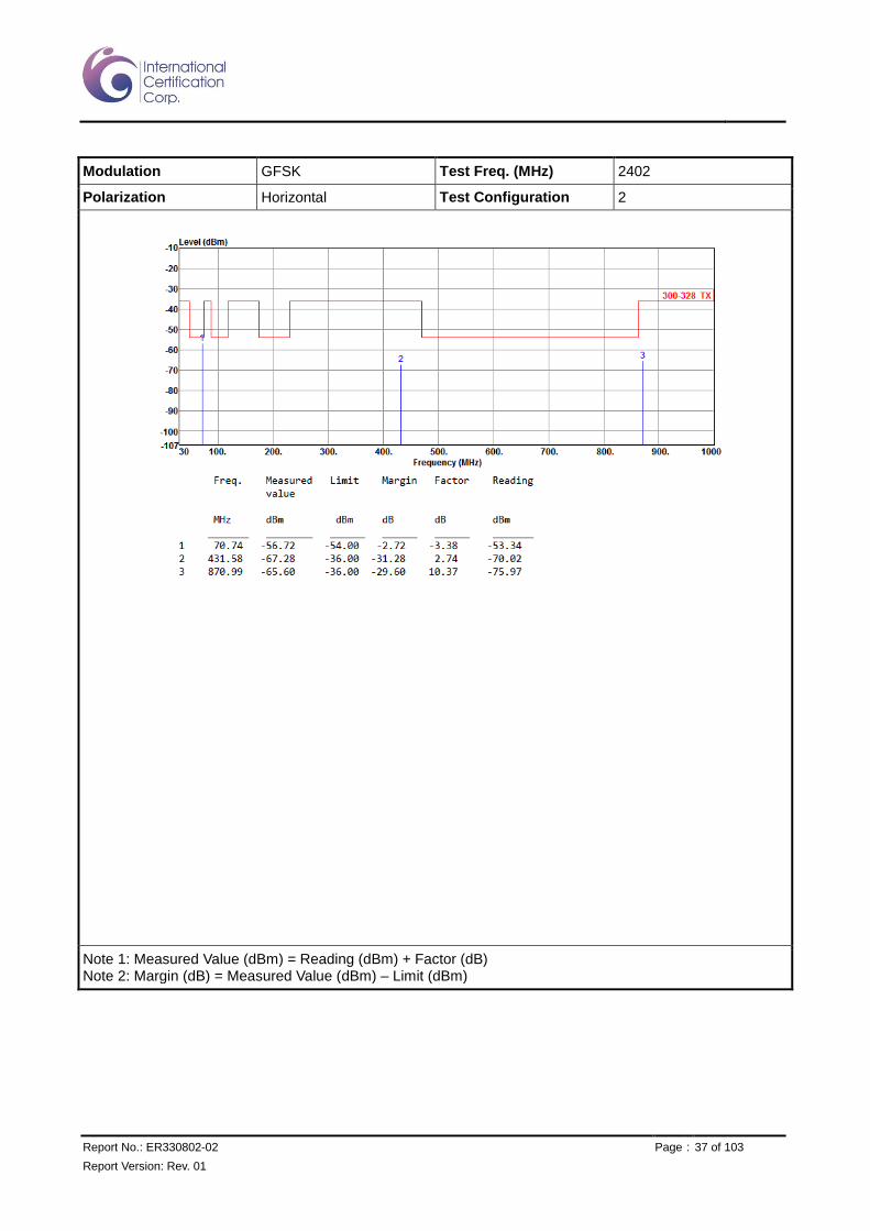
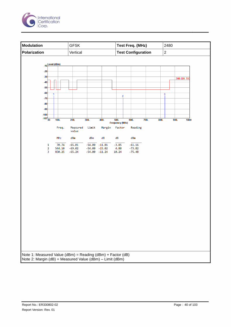
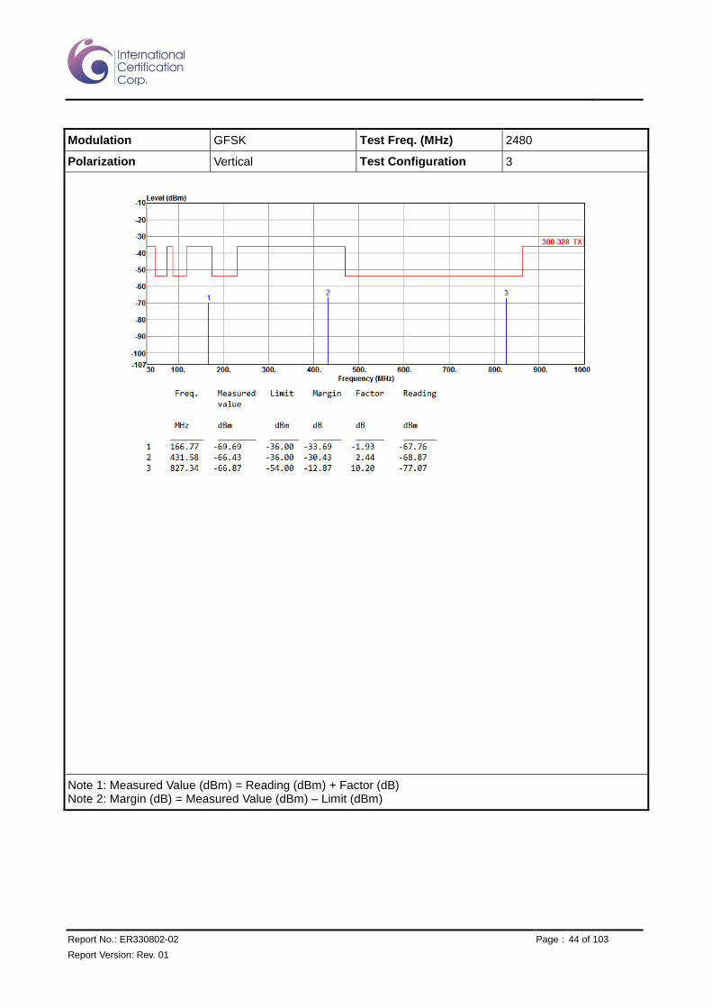
3.5.4 Transmitter Spurious Unwanted Emissions (Below 1GHz)
Modulation GFSK Test Freq. (MHz) 2402
Polarization Horizontal Test Configuration 1
Note 1: Measured Value (dBm) = Reading (dBm) + Factor (dB) Note 2: Margin (dB) = Measured Value (dBm) – Limit (dBm)

Report No.: ER330802-02 Page : 34 of 103
Report Version: Rev. 01
Modulation GFSK Test Freq. (MHz) 2402
Polarization Vertical Test Configuration 1
Note 1: Measured Value (dBm) = Reading (dBm) + Factor (dB) Note 2: Margin (dB) = Measured Value (dBm) – Limit (dBm)
Report No.: ER330802-02 Page : 35 of 103
Report Version: Rev. 01
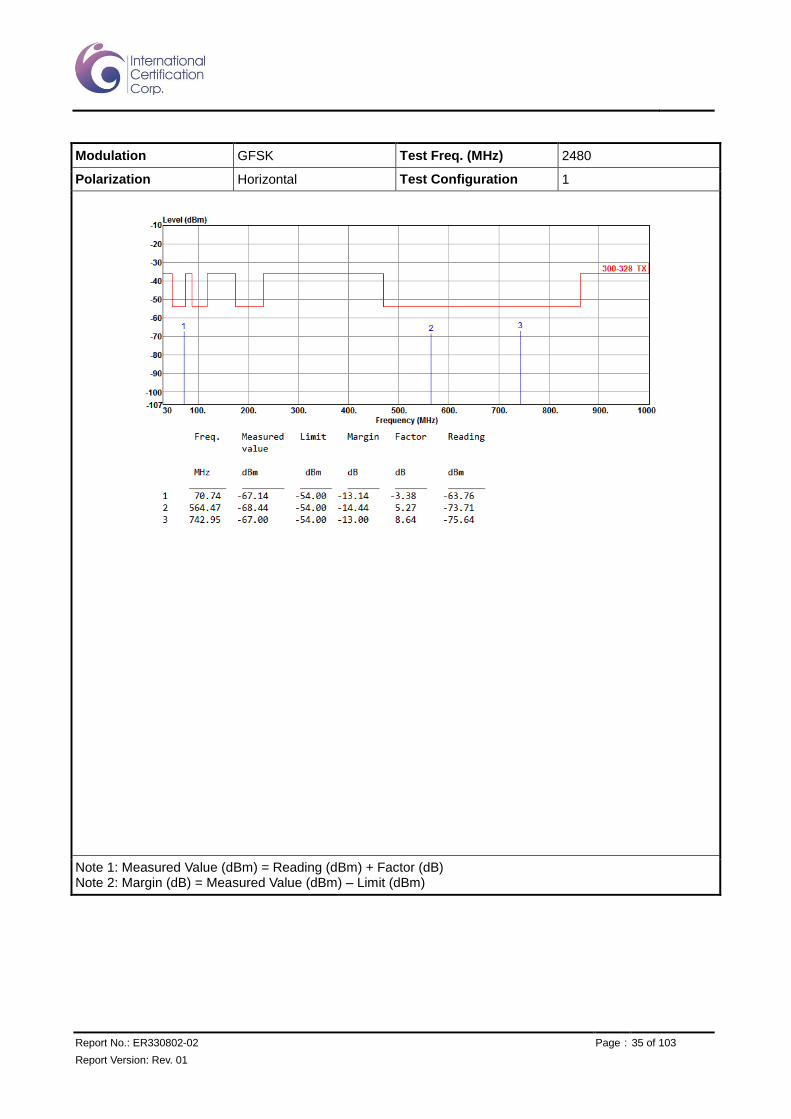
Modulation GFSK Test Freq. (MHz) 2480
Polarization Horizontal Test Configuration 1
Note 1: Measured Value (dBm) = Reading (dBm) + Factor (dB) Note 2: Margin (dB) = Measured Value (dBm) – Limit (dBm)

Report No.: ER330802-02 Page : 36 of 103
Report Version: Rev. 01
Modulation GFSK Test Freq. (MHz) 2480
Polarization Vertical Test Configuration 1
Note 1: Measured Value (dBm) = Reading (dBm) + Factor (dB) Note 2: Margin (dB) = Measured Value (dBm) – Limit (dBm)
Report No.: ER330802-02 Page : 37 of 103
Report Version: Rev. 01
Modulation GFSK Test Freq. (MHz) 2402
Polarization Horizontal Test Configuration 2
Note 1: Measured Value (dBm) = Reading (dBm) + Factor (dB) Note 2: Margin (dB) = Measured Value (dBm) – Limit (dBm)

Report No.: ER330802-02 Page : 38 of 103
Report Version: Rev. 01
Modulation GFSK Test Freq. (MHz) 2402
Polarization Vertical Test Configuration 2
Note 1: Measured Value (dBm) = Reading (dBm) + Factor (dB) Note 2: Margin (dB) = Measured Value (dBm) – Limit (dBm)

Report No.: ER330802-02 Page : 39 of 103
Report Version: Rev. 01
Modulation GFSK Test Freq. (MHz) 2480
Polarization Horizontal Test Configuration 2
Note 1: Measured Value (dBm) = Reading (dBm) + Factor (dB) Note 2: Margin (dB) = Measured Value (dBm) – Limit (dBm)
Report No.: ER330802-02 Page : 40 of 103
Report Version: Rev. 01
Modulation GFSK Test Freq. (MHz) 2480
Polarization Vertical Test Configuration 2
Note 1: Measured Value (dBm) = Reading (dBm) + Factor (dB) Note 2: Margin (dB) = Measured Value (dBm) – Limit (dBm)

Report No.: ER330802-02 Page : 41 of 103
Report Version: Rev. 01
Modulation GFSK Test Freq. (MHz) 2402
Polarization Horizontal Test Configuration 3
Note 1: Measured Value (dBm) = Reading (dBm) + Factor (dB) Note 2: Margin (dB) = Measured Value (dBm) – Limit (dBm)

Report No.: ER330802-02 Page : 42 of 103
Report Version: Rev. 01
Modulation GFSK Test Freq. (MHz) 2402
Polarization Vertical Test Configuration 3
Note 1: Measured Value (dBm) = Reading (dBm) + Factor (dB) Note 2: Margin (dB) = Measured Value (dBm) – Limit (dBm)

Report No.: ER330802-02 Page : 43 of 103
Report Version: Rev. 01
Modulation GFSK Test Freq. (MHz) 2480
Polarization Horizontal Test Configuration 3
Note 1: Measured Value (dBm) = Reading (dBm) + Factor (dB) Note 2: Margin (dB) = Measured Value (dBm) – Limit (dBm)
Report No.: ER330802-02 Page : 44 of 103
Report Version: Rev. 01
Modulation GFSK Test Freq. (MHz) 2480
Polarization Vertical Test Configuration 3
Note 1: Measured Value (dBm) = Reading (dBm) + Factor (dB) Note 2: Margin (dB) = Measured Value (dBm) – Limit (dBm)

Report No.: ER330802-02 Page : 45 of 103
Report Version: Rev. 01
Modulation GFSK Test Freq. (MHz) 2402
Polarization Horizontal Test Configuration 4
Note 1: Measured Value (dBm) = Reading (dBm) + Factor (dB) Note 2: Margin (dB) = Measured Value (dBm) – Limit (dBm)

Report No.: ER330802-02 Page : 46 of 103
Report Version: Rev. 01
Modulation GFSK Test Freq. (MHz) 2402
Polarization Vertical Test Configuration 4
Note 1: Measured Value (dBm) = Reading (dBm) + Factor (dB) Note 2: Margin (dB) = Measured Value (dBm) – Limit (dBm)

Report No.: ER330802-02 Page : 47 of 103
Report Version: Rev. 01
Modulation GFSK Test Freq. (MHz) 2480
Polarization Horizontal Test Configuration 4
Note 1: Measured Value (dBm) = Reading (dBm) + Factor (dB) Note 2: Margin (dB) = Measured Value (dBm) – Limit (dBm)

Report No.: ER330802-02 Page : 48 of 103
Report Version: Rev. 01
Modulation GFSK Test Freq. (MHz) 2480
Polarization Vertical Test Configuration 4
Note 1: Measured Value (dBm) = Reading (dBm) + Factor (dB) Note 2: Margin (dB) = Measured Value (dBm) – Limit (dBm)

Report No.: ER330802-02 Page : 49 of 103
Report Version: Rev. 01
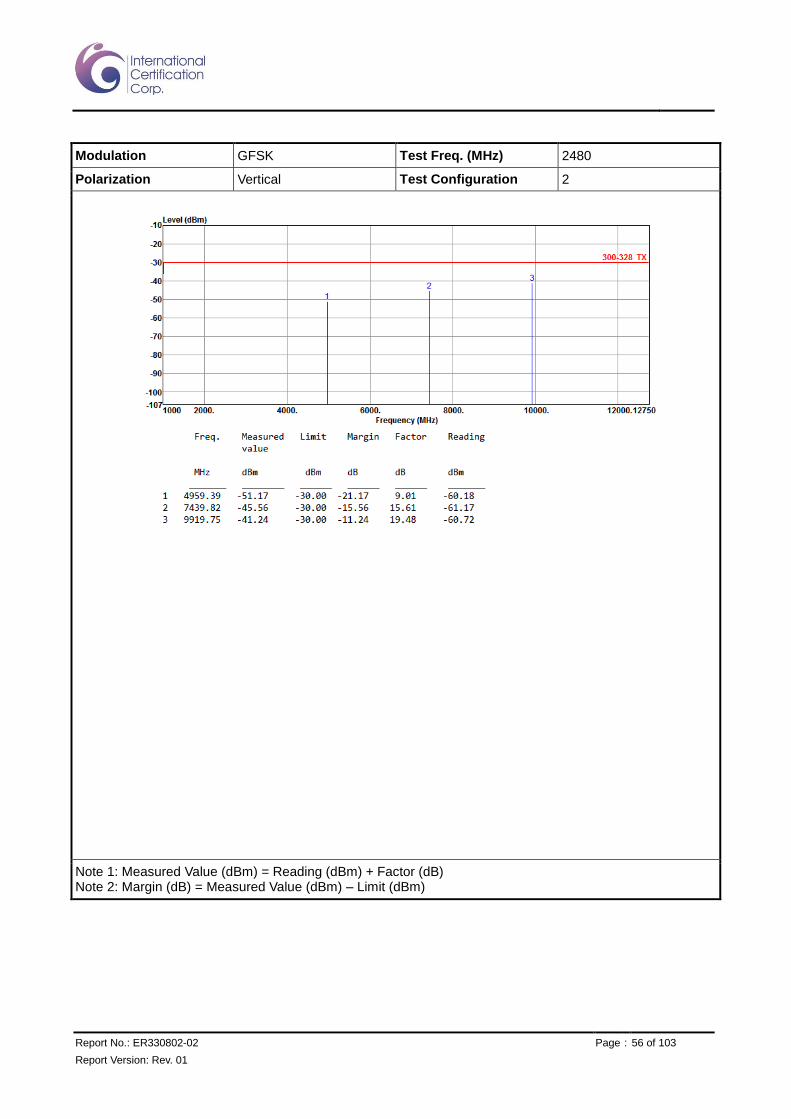
3.5.5 Transmitter Spurious Unwanted Emissions (Above 1GHz)
Modulation GFSK Test Freq. (MHz) 2402
Polarization Horizontal Test Configuration 1
Note 1: Measured Value (dBm) = Reading (dBm) + Factor (dB) Note 2: Margin (dB) = Measured Value (dBm) – Limit (dBm)

Report No.: ER330802-02 Page : 50 of 103
Report Version: Rev. 01
Modulation GFSK Test Freq. (MHz) 2402
Polarization Vertical Test Configuration 1
Note 1: Measured Value (dBm) = Reading (dBm) + Factor (dB) Note 2: Margin (dB) = Measured Value (dBm) – Limit (dBm)

Report No.: ER330802-02 Page : 51 of 103
Report Version: Rev. 01
Modulation GFSK Test Freq. (MHz) 2480
Polarization Horizontal Test Configuration 1
Note 1: Measured Value (dBm) = Reading (dBm) + Factor (dB) Note 2: Margin (dB) = Measured Value (dBm) – Limit (dBm)

Report No.: ER330802-02 Page : 52 of 103
Report Version: Rev. 01
Modulation GFSK Test Freq. (MHz) 2480
Polarization Vertical Test Configuration 1
Note 1: Measured Value (dBm) = Reading (dBm) + Factor (dB) Note 2: Margin (dB) = Measured Value (dBm) – Limit (dBm)

Report No.: ER330802-02 Page : 53 of 103
Report Version: Rev. 01
Modulation GFSK Test Freq. (MHz) 2402
Polarization Horizontal Test Configuration 2
Note 1: Measured Value (dBm) = Reading (dBm) + Factor (dB) Note 2: Margin (dB) = Measured Value (dBm) – Limit (dBm)

Report No.: ER330802-02 Page : 54 of 103
Report Version: Rev. 01
Modulation GFSK Test Freq. (MHz) 2402
Polarization Vertical Test Configuration 2
Note 1: Measured Value (dBm) = Reading (dBm) + Factor (dB) Note 2: Margin (dB) = Measured Value (dBm) – Limit (dBm)

Report No.: ER330802-02 Page : 55 of 103
Report Version: Rev. 01
Modulation GFSK Test Freq. (MHz) 2480
Polarization Horizontal Test Configuration 2
Note 1: Measured Value (dBm) = Reading (dBm) + Factor (dB) Note 2: Margin (dB) = Measured Value (dBm) – Limit (dBm)
Report No.: ER330802-02 Page : 56 of 103
Report Version: Rev. 01
Modulation GFSK Test Freq. (MHz) 2480
Polarization Vertical Test Configuration 2
Note 1: Measured Value (dBm) = Reading (dBm) + Factor (dB) Note 2: Margin (dB) = Measured Value (dBm) – Limit (dBm)

Report No.: ER330802-02 Page : 57 of 103
Report Version: Rev. 01
Modulation GFSK Test Freq. (MHz) 2402
Polarization Horizontal Test Configuration 3
Note 1: Measured Value (dBm) = Reading (dBm) + Factor (dB) Note 2: Margin (dB) = Measured Value (dBm) – Limit (dBm)

Report No.: ER330802-02 Page : 58 of 103
Report Version: Rev. 01
Modulation GFSK Test Freq. (MHz) 2402
Polarization Vertical Test Configuration 3
Note 1: Measured Value (dBm) = Reading (dBm) + Factor (dB) Note 2: Margin (dB) = Measured Value (dBm) – Limit (dBm)

Report No.: ER330802-02 Page : 59 of 103
Report Version: Rev. 01
Modulation GFSK Test Freq. (MHz) 2480
Polarization Horizontal Test Configuration 3
Note 1: Measured Value (dBm) = Reading (dBm) + Factor (dB) Note 2: Margin (dB) = Measured Value (dBm) – Limit (dBm)

Report No.: ER330802-02 Page : 60 of 103
Report Version: Rev. 01
Modulation GFSK Test Freq. (MHz) 2480
Polarization Vertical Test Configuration 3
Note 1: Measured Value (dBm) = Reading (dBm) + Factor (dB) Note 2: Margin (dB) = Measured Value (dBm) – Limit (dBm)

Report No.: ER330802-02 Page : 61 of 103
Report Version: Rev. 01
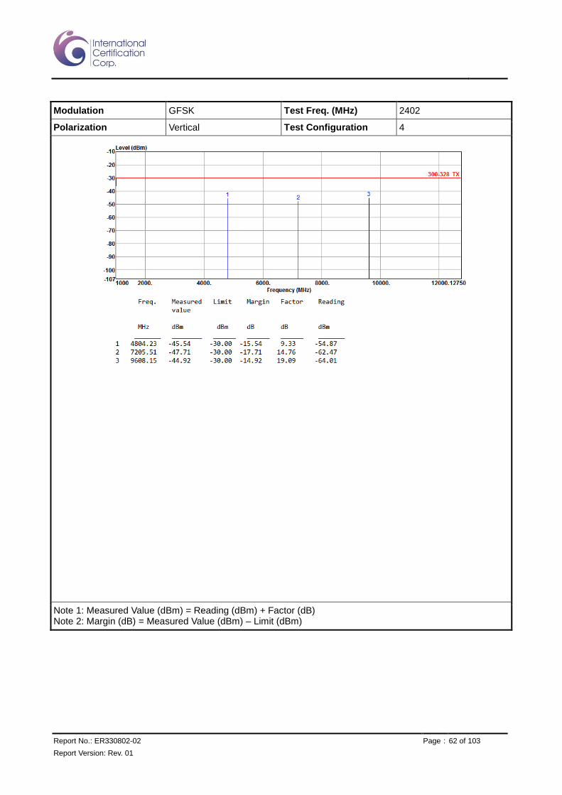
Modulation GFSK Test Freq. (MHz) 2402
Polarization Horizontal Test Configuration 4
Note 1: Measured Value (dBm) = Reading (dBm) + Factor (dB) Note 2: Margin (dB) = Measured Value (dBm) – Limit (dBm)
Report No.: ER330802-02 Page : 62 of 103
Report Version: Rev. 01
Modulation GFSK Test Freq. (MHz) 2402
Polarization Vertical Test Configuration 4
Note 1: Measured Value (dBm) = Reading (dBm) + Factor (dB) Note 2: Margin (dB) = Measured Value (dBm) – Limit (dBm)

Report No.: ER330802-02 Page : 63 of 103
Report Version: Rev. 01
Modulation GFSK Test Freq. (MHz) 2480
Polarization Horizontal Test Configuration 4
Note 1: Measured Value (dBm) = Reading (dBm) + Factor (dB) Note 2: Margin (dB) = Measured Value (dBm) – Limit (dBm)

Report No.: ER330802-02 Page : 64 of 103
Report Version: Rev. 01
Modulation GFSK Test Freq. (MHz) 2480
Polarization Vertical Test Configuration 4
Note 1: Measured Value (dBm) = Reading (dBm) + Factor (dB) Note 2: Margin (dB) = Measured Value (dBm) – Limit (dBm)

Report No.: ER330802-02 Page : 65 of 103
Report Version: Rev. 01
4 Receiver Test Results
4.1 Receiver Spurious Emissions
4.1.1 Limit of Receiver Spurious Emissions
Frequency Range Maximum power (dBm) Measurement bandwidth (kHz)
30 MHz to 1 GHz -57 100
Above 1 GHz to 12.75 GHz -47 1000
4.1.2 Test Procedures
Reference to clause 5.3.11.2 of ETSI EN 300 328 V1.9.1 (2015-02).

Report No.: ER330802-02 Page : 66 of 103
Report Version: Rev. 01
4.1.3 Test Setup
Below 1GHz
Above 1 GHz

Report No.: ER330802-02 Page : 67 of 103
Report Version: Rev. 01
4.1.4 Receiver Spurious Unwanted Emissions (Below 1GHz)
Modulation GFSK Test Freq. (MHz) 2402
Polarization Horizontal Test Configuration 1
Note 1: Measured Value (dBm) = Reading (dBm) + Factor (dB) Note 2: Margin (dB) = Measured Value (dBm) – Limit (dBm)

Report No.: ER330802-02 Page : 68 of 103
Report Version: Rev. 01
Modulation GFSK Test Freq. (MHz) 2402
Polarization Vertical Test Configuration 1
Note 1: Measured Value (dBm) = Reading (dBm) + Factor (dB) Note 2: Margin (dB) = Measured Value (dBm) – Limit (dBm)

Report No.: ER330802-02 Page : 69 of 103
Report Version: Rev. 01
Modulation GFSK Test Freq. (MHz) 2480
Polarization Horizontal Test Configuration 1
Note 1: Measured Value (dBm) = Reading (dBm) + Factor (dB) Note 2: Margin (dB) = Measured Value (dBm) – Limit (dBm)

Report No.: ER330802-02 Page : 70 of 103
Report Version: Rev. 01
Modulation GFSK Test Freq. (MHz) 2480
Polarization Vertical Test Configuration 1
Note 1: Measured Value (dBm) = Reading (dBm) + Factor (dB) Note 2: Margin (dB) = Measured Value (dBm) – Limit (dBm)

Report No.: ER330802-02 Page : 71 of 103
Report Version: Rev. 01
Modulation GFSK Test Freq. (MHz) 2402
Polarization Horizontal Test Configuration 2
Note 1: Measured Value (dBm) = Reading (dBm) + Factor (dB) Note 2: Margin (dB) = Measured Value (dBm) – Limit (dBm)
Report No.: ER330802-02 Page : 72 of 103
Report Version: Rev. 01
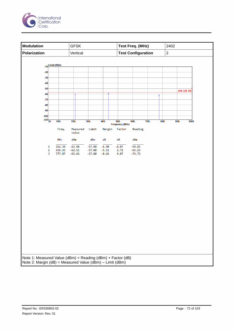
Modulation GFSK Test Freq. (MHz) 2402
Polarization Vertical Test Configuration 2
Note 1: Measured Value (dBm) = Reading (dBm) + Factor (dB) Note 2: Margin (dB) = Measured Value (dBm) – Limit (dBm)

Report No.: ER330802-02 Page : 73 of 103
Report Version: Rev. 01
Modulation GFSK Test Freq. (MHz) 2480
Polarization Horizontal Test Configuration 2
Note 1: Measured Value (dBm) = Reading (dBm) + Factor (dB) Note 2: Margin (dB) = Measured Value (dBm) – Limit (dBm)

Report No.: ER330802-02 Page : 74 of 103
Report Version: Rev. 01
Modulation GFSK Test Freq. (MHz) 2480
Polarization Vertical Test Configuration 2
Note 1: Measured Value (dBm) = Reading (dBm) + Factor (dB) Note 2: Margin (dB) = Measured Value (dBm) – Limit (dBm)
Report No.: ER330802-02 Page : 75 of 103
Report Version: Rev. 01
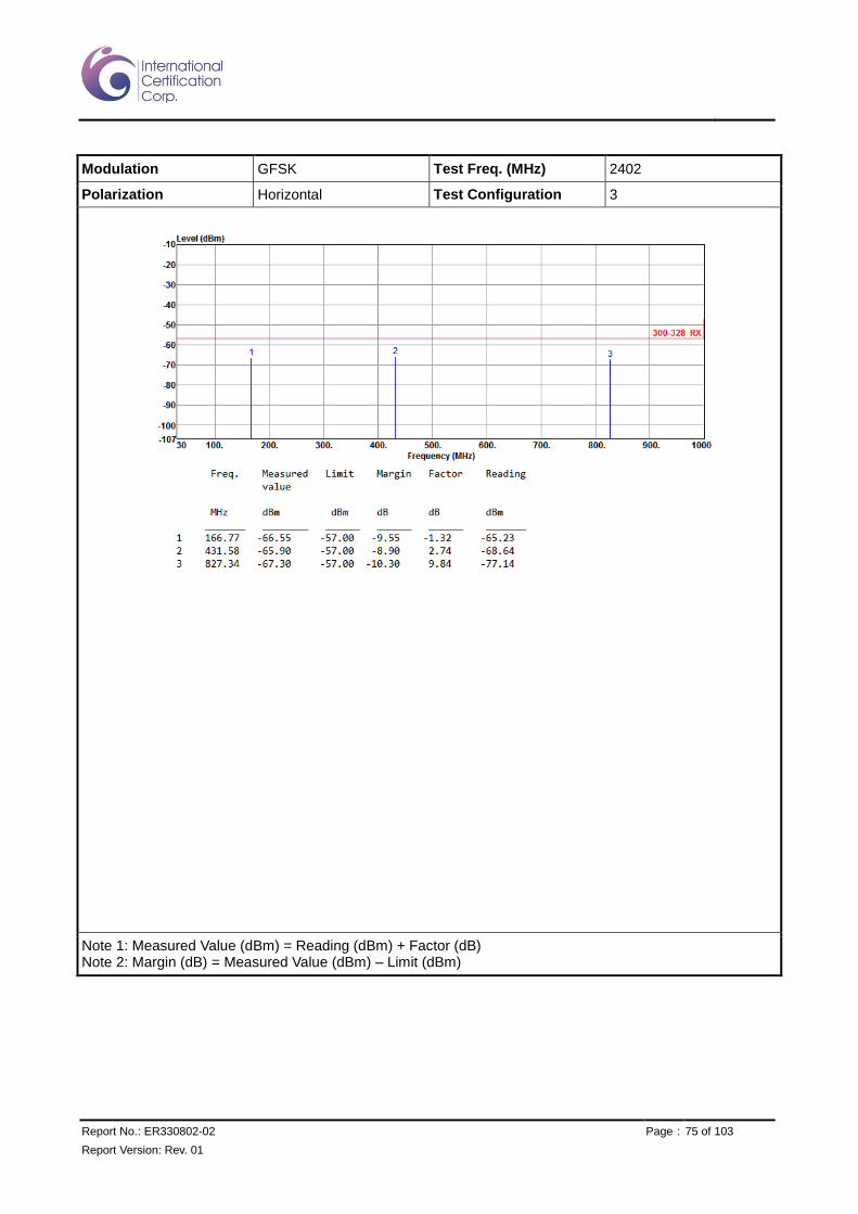
Modulation GFSK Test Freq. (MHz) 2402
Polarization Horizontal Test Configuration 3
Note 1: Measured Value (dBm) = Reading (dBm) + Factor (dB) Note 2: Margin (dB) = Measured Value (dBm) – Limit (dBm)

Report No.: ER330802-02 Page : 76 of 103
Report Version: Rev. 01
Modulation GFSK Test Freq. (MHz) 2402
Polarization Vertical Test Configuration 3
Note 1: Measured Value (dBm) = Reading (dBm) + Factor (dB) Note 2: Margin (dB) = Measured Value (dBm) – Limit (dBm)

Report No.: ER330802-02 Page : 77 of 103
Report Version: Rev. 01
Modulation GFSK Test Freq. (MHz) 2480
Polarization Horizontal Test Configuration 3
Note 1: Measured Value (dBm) = Reading (dBm) + Factor (dB) Note 2: Margin (dB) = Measured Value (dBm) – Limit (dBm)

Report No.: ER330802-02 Page : 78 of 103
Report Version: Rev. 01
Modulation GFSK Test Freq. (MHz) 2480
Polarization Vertical Test Configuration 3
Note 1: Measured Value (dBm) = Reading (dBm) + Factor (dB) Note 2: Margin (dB) = Measured Value (dBm) – Limit (dBm)

Report No.: ER330802-02 Page : 79 of 103
Report Version: Rev. 01
Modulation GFSK Test Freq. (MHz) 2402
Polarization Horizontal Test Configuration 4
Note 1: Measured Value (dBm) = Reading (dBm) + Factor (dB) Note 2: Margin (dB) = Measured Value (dBm) – Limit (dBm)
Report No.: ER330802-02 Page : 80 of 103
Report Version: Rev. 01
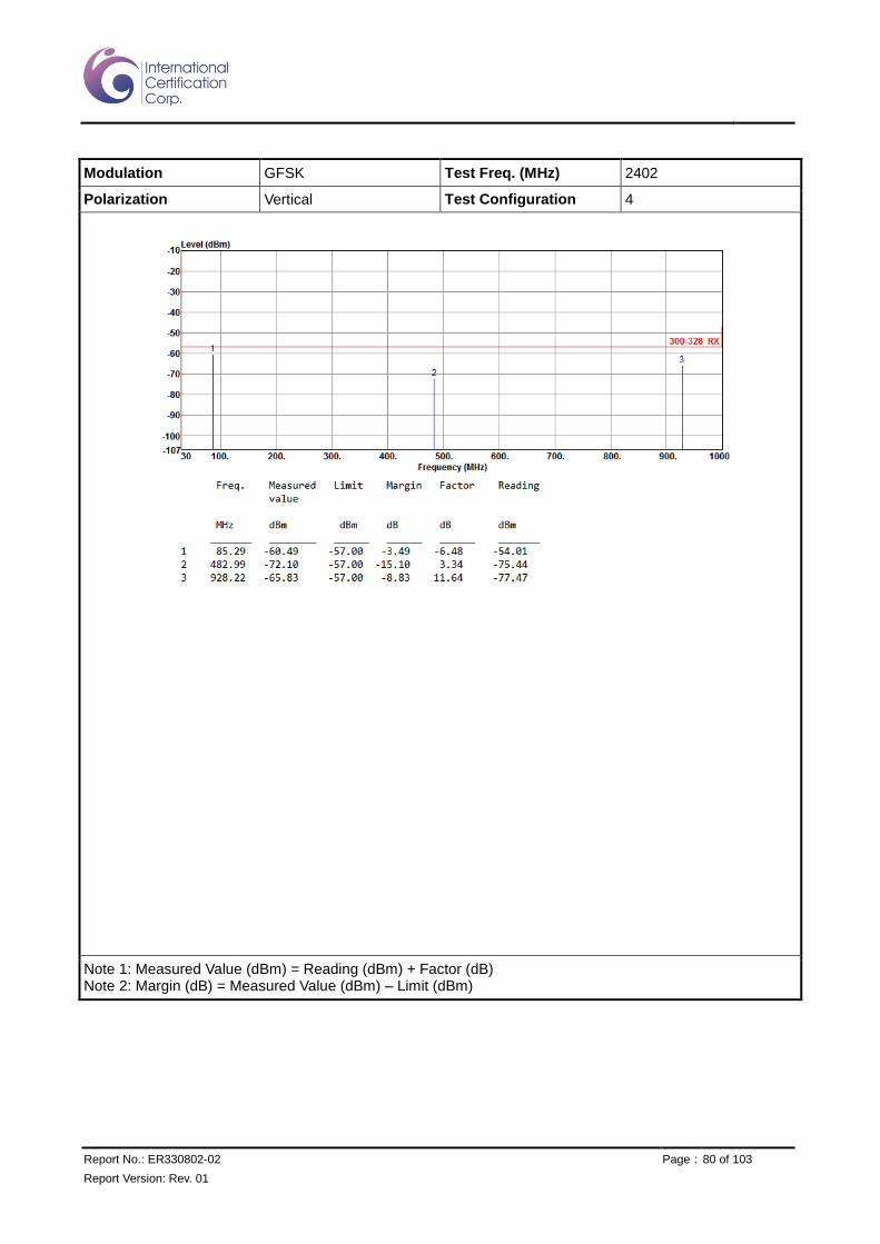
Modulation GFSK Test Freq. (MHz) 2402
Polarization Vertical Test Configuration 4
Note 1: Measured Value (dBm) = Reading (dBm) + Factor (dB) Note 2: Margin (dB) = Measured Value (dBm) – Limit (dBm)

Report No.: ER330802-02 Page : 81 of 103
Report Version: Rev. 01
Modulation GFSK Test Freq. (MHz) 2480
Polarization Horizontal Test Configuration 4
Note 1: Measured Value (dBm) = Reading (dBm) + Factor (dB) Note 2: Margin (dB) = Measured Value (dBm) – Limit (dBm)

Report No.: ER330802-02 Page : 82 of 103
Report Version: Rev. 01
Modulation GFSK Test Freq. (MHz) 2480
Polarization Vertical Test Configuration 4
Note 1: Measured Value (dBm) = Reading (dBm) + Factor (dB) Note 2: Margin (dB) = Measured Value (dBm) – Limit (dBm)
Report No.: ER330802-02 Page : 83 of 103
Report Version: Rev. 01
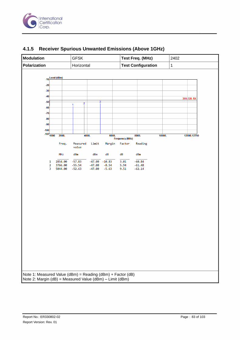
4.1.5 Receiver Spurious Unwanted Emissions (Above 1GHz)
Modulation GFSK Test Freq. (MHz) 2402
Polarization Horizontal Test Configuration 1
Note 1: Measured Value (dBm) = Reading (dBm) + Factor (dB) Note 2: Margin (dB) = Measured Value (dBm) – Limit (dBm)
Report No.: ER330802-02 Page : 84 of 103
Report Version: Rev. 01
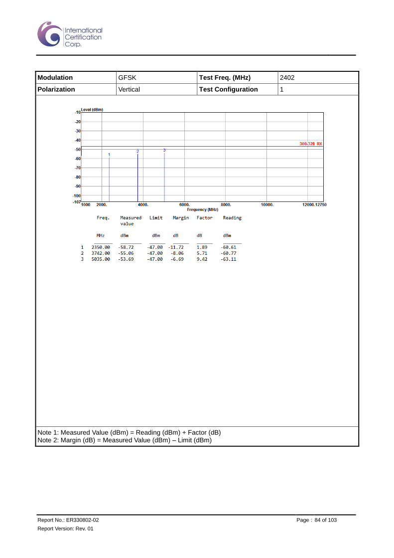
Modulation GFSK Test Freq. (MHz) 2402
Polarization Vertical Test Configuration 1
Note 1: Measured Value (dBm) = Reading (dBm) + Factor (dB) Note 2: Margin (dB) = Measured Value (dBm) – Limit (dBm)

Report No.: ER330802-02 Page : 85 of 103
Report Version: Rev. 01
Modulation GFSK Test Freq. (MHz) 2480
Polarization Horizontal Test Configuration 1
Note 1: Measured Value (dBm) = Reading (dBm) + Factor (dB) Note 2: Margin (dB) = Measured Value (dBm) – Limit (dBm)

Report No.: ER330802-02 Page : 86 of 103
Report Version: Rev. 01
Modulation GFSK Test Freq. (MHz) 2480
Polarization Vertical Test Configuration 1
Note 1: Measured Value (dBm) = Reading (dBm) + Factor (dB) Note 2: Margin (dB) = Measured Value (dBm) – Limit (dBm)

Report No.: ER330802-02 Page : 87 of 103
Report Version: Rev. 01
Modulation GFSK Test Freq. (MHz) 2402
Polarization Horizontal Test Configuration 2
Note 1: Measured Value (dBm) = Reading (dBm) + Factor (dB) Note 2: Margin (dB) = Measured Value (dBm) – Limit (dBm)

Report No.: ER330802-02 Page : 88 of 103
Report Version: Rev. 01
Modulation GFSK Test Freq. (MHz) 2402
Polarization Vertical Test Configuration 2
Note 1: Measured Value (dBm) = Reading (dBm) + Factor (dB) Note 2: Margin (dB) = Measured Value (dBm) – Limit (dBm)

Report No.: ER330802-02 Page : 89 of 103
Report Version: Rev. 01
Modulation GFSK Test Freq. (MHz) 2480
Polarization Horizontal Test Configuration 2
Note 1: Measured Value (dBm) = Reading (dBm) + Factor (dB) Note 2: Margin (dB) = Measured Value (dBm) – Limit (dBm)
Report No.: ER330802-02 Page : 90 of 103
Report Version: Rev. 01
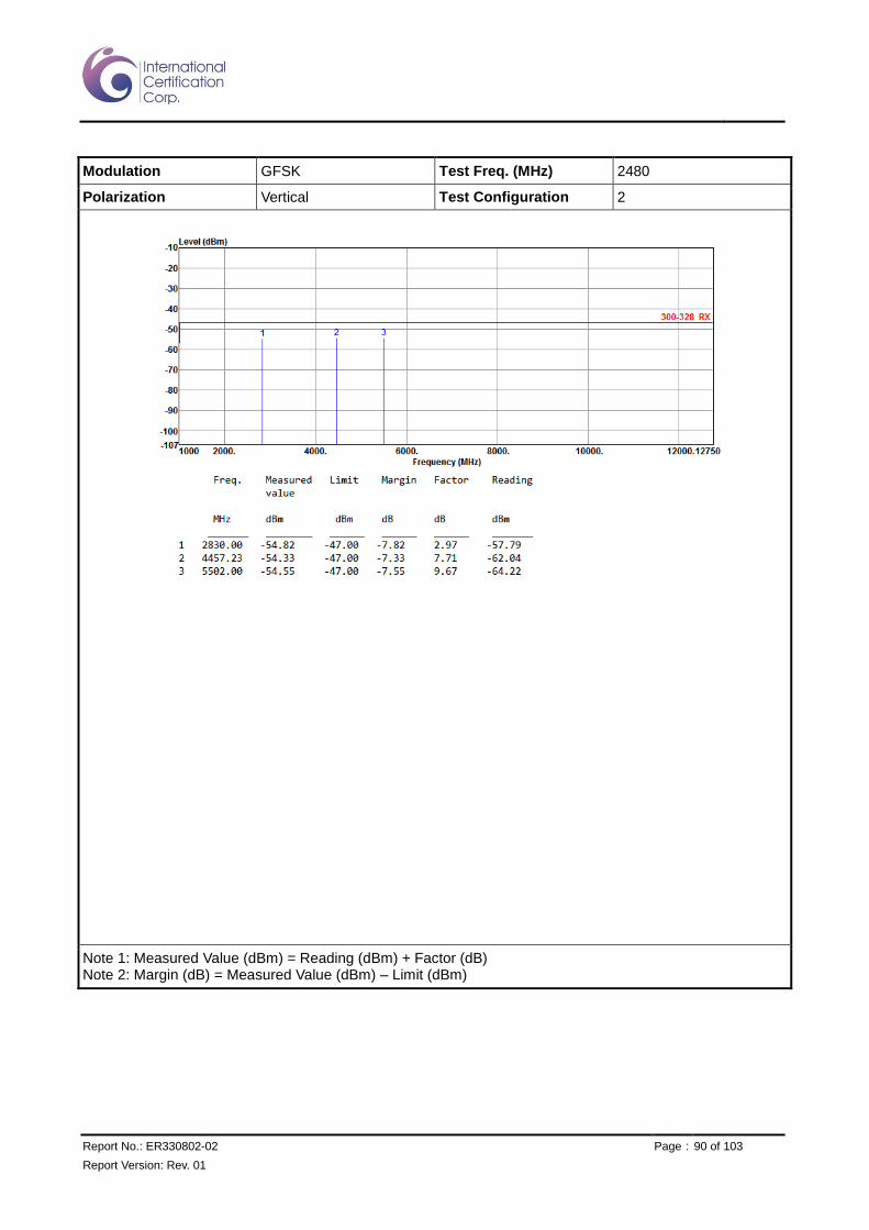
Modulation GFSK Test Freq. (MHz) 2480
Polarization Vertical Test Configuration 2
Note 1: Measured Value (dBm) = Reading (dBm) + Factor (dB) Note 2: Margin (dB) = Measured Value (dBm) – Limit (dBm)

Report No.: ER330802-02 Page : 91 of 103
Report Version: Rev. 01
Modulation GFSK Test Freq. (MHz) 2402
Polarization Horizontal Test Configuration 3
Note 1: Measured Value (dBm) = Reading (dBm) + Factor (dB) Note 2: Margin (dB) = Measured Value (dBm) – Limit (dBm)

Report No.: ER330802-02 Page : 92 of 103
Report Version: Rev. 01
Modulation GFSK Test Freq. (MHz) 2402
Polarization Vertical Test Configuration 3
Note 1: Measured Value (dBm) = Reading (dBm) + Factor (dB) Note 2: Margin (dB) = Measured Value (dBm) – Limit (dBm)

Report No.: ER330802-02 Page : 93 of 103
Report Version: Rev. 01
Modulation GFSK Test Freq. (MHz) 2480
Polarization Horizontal Test Configuration 3
Note 1: Measured Value (dBm) = Reading (dBm) + Factor (dB) Note 2: Margin (dB) = Measured Value (dBm) – Limit (dBm)

Report No.: ER330802-02 Page : 94 of 103
Report Version: Rev. 01
Modulation GFSK Test Freq. (MHz) 2480
Polarization Vertical Test Configuration 3
Note 1: Measured Value (dBm) = Reading (dBm) + Factor (dB) Note 2: Margin (dB) = Measured Value (dBm) – Limit (dBm)

Report No.: ER330802-02 Page : 95 of 103
Report Version: Rev. 01
Modulation GFSK Test Freq. (MHz) 2402
Polarization Horizontal Test Configuration 4
Note 1: Measured Value (dBm) = Reading (dBm) + Factor (dB) Note 2: Margin (dB) = Measured Value (dBm) – Limit (dBm)

Report No.: ER330802-02 Page : 96 of 103
Report Version: Rev. 01
Modulation GFSK Test Freq. (MHz) 2402
Polarization Vertical Test Configuration 4
Note 1: Measured Value (dBm) = Reading (dBm) + Factor (dB) Note 2: Margin (dB) = Measured Value (dBm) – Limit (dBm)

Report No.: ER330802-02 Page : 97 of 103
Report Version: Rev. 01
Modulation GFSK Test Freq. (MHz) 2480
Polarization Horizontal Test Configuration 4
Note 1: Measured Value (dBm) = Reading (dBm) + Factor (dB) Note 2: Margin (dB) = Measured Value (dBm) – Limit (dBm)

Report No.: ER330802-02 Page : 98 of 103
Report Version: Rev. 01
Modulation GFSK Test Freq. (MHz) 2480
Polarization Vertical Test Configuration 4
Note 1: Measured Value (dBm) = Reading (dBm) + Factor (dB) Note 2: Margin (dB) = Measured Value (dBm) – Limit (dBm)
Report No.: ER330802-02 Page : 99 of 103
Report Version: Rev. 01
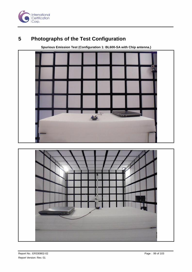
5 Photographs of the Test Configuration
Spurious Emission Test (Configuration 1: BL600-SA with Chip antenna.)

Report No.: ER330802-02 Page : 100 of 103
Report Version: Rev. 01
Spurious Emission Test (Configuration 2: BL600-SC with PCB Dipole antenna)
Report No.: ER330802-02 Page : 101 of 103
Report Version: Rev. 01
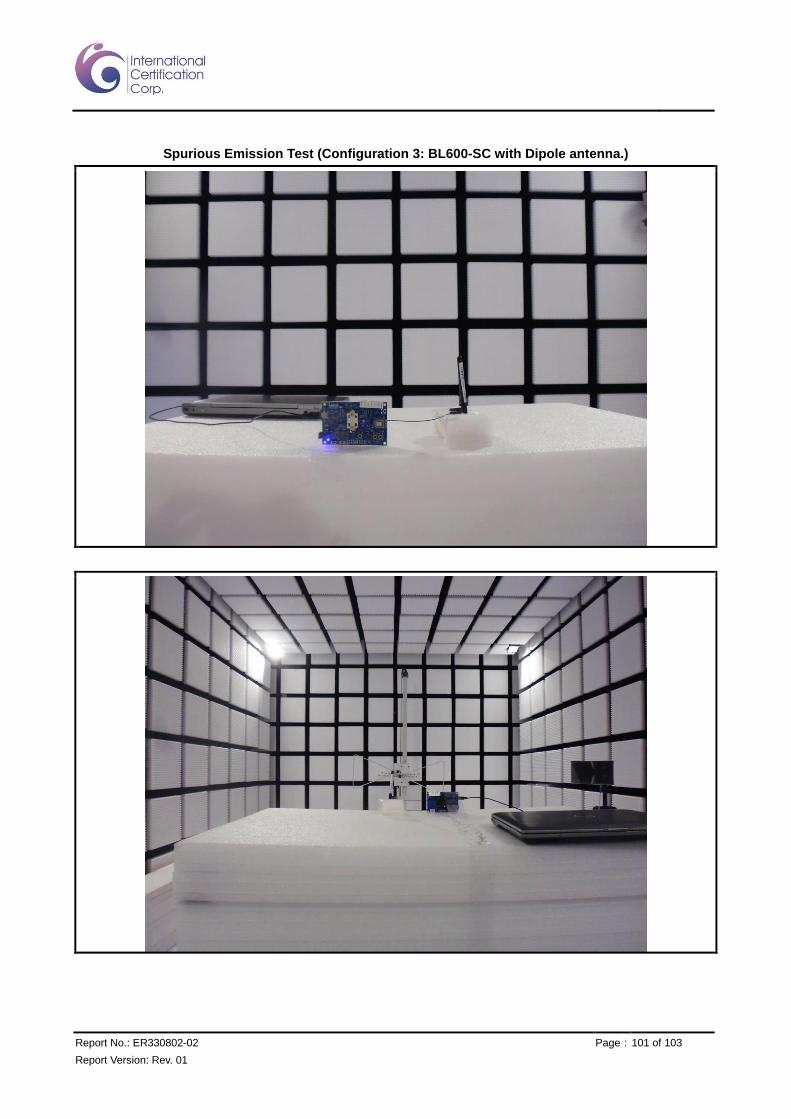
Spurious Emission Test (Configuration 3: BL600-SC with Dipole antenna.)

Report No.: ER330802-02 Page : 102 of 103
Report Version: Rev. 01
Spurious Emission Test (Configuration 4: BL600-ST with Dipole antenna)

Report No.: ER330802-02 Page : 103 of 103
Report Version: Rev. 01
6 Test laboratory information
Established in 2012, ICC provides foremost EMC & RF Testing and advisory consultation services by our
skilled engineers and technicians. Our services employ a wide variety of advanced edge test equipment and
one of the widest certification extents in the business.
International Certification Corp, it is our definitive objective is to institute long term, trust-based associations
with our clients. The expectation we set up with our clients is based on outstanding service, practical expertise
and devotion to a certified value structure. Our passion is to grant our clients with best EMC / RF services by
oriented knowledgeable and accommodating staff.
Our Test sites are located at Linkou District and Kwei Shan Hsiang. Location map can be found on our
website http://www.icertifi.com.tw.
Linkou Kwei Shan Kwei Shan Site II
Tel: 886-2-2601-1640 Tel: 886-3-271-8666 Tel: 886-3-271-8640
No. 30-2, Ding Fwu Tsuen, Lin Kou District, New Taipei City, Taiwan, R.O.C.
No. 3-1, Lane 6, Wen San 3rd St., Kwei Shan Hsiang, Tao Yuan Hsien 333, Taiwan, R.O.C.
No. 14-1, Lane 19, Wen San 3rd St., Kwei Shan Hsiang, Tao Yuan Hsien 333, Taiwan, R.O.C.
If you have any suggestion, please feel free to contact us as below information
Tel: 886-3-271-8666
Fax: 886-3-318-0155
Email: [email protected]
══END══