ce regulations for srds operating in license-free 2.4ghz
TRANSCRIPT

1SWRA670–April 2020Submit Documentation Feedback
Copyright © 2020, Texas Instruments Incorporated
CE Regulations for SRDs Operating in License-Free 2.4 GHz/5 GHz Bands
Application ReportSWRA670–April 2020
CE Regulations for SRDs Operating in License-Free 2.4GHz/5 GHz Bands
Prasad Movva
ABSTRACTThis application report covers the requirements and procedures for license-free operation of radioequipment in the worldwide 2.4 GHz and 5 GHz bands for regulatory compliance in Europe. The CEregulations for SRD (Short-Range Devices) are covered in detail for both transmitters and receivers in thefrequency bands of both 2.4 GHz and 5 GHz. Note that this application report serves as guidance onCE compliance test limits on the 2.4 GHz and 5 GHz bands. For detailed requirements, refer toETSI documentation.
Contents1 Introduction ................................................................................................................... 42 Regulation Overview ........................................................................................................ 53 Radio Equipment Directive (RED) ......................................................................................... 84 ETSI EN 300 440........................................................................................................... 125 ETSI EN 300 328........................................................................................................... 186 ETSI EN 301 893........................................................................................................... 367 ETSI EN 301 489........................................................................................................... 548 IEC 62368-1................................................................................................................. 669 EN 62311.................................................................................................................... 6710 References .................................................................................................................. 69
List of Figures
1 Pictogram Example ........................................................................................................ 112 Transmit Spectral Power Mask........................................................................................... 413 Example of timing for Frame Based Equipment ....................................................................... 454 Channel Bonding for option 2............................................................................................. 48
List of Tables
1 CEPT ERC Recommendation 70-03 for the 2.4 GHz and 5 GHz Frequency Bands............................... 62 Limits on Permitted Frequency Bands in 2.4 GHz and 5 GHz Bands - EN 300 440.............................. 123 Technical Requirements and Conditions - EN 300 440............................................................... 124 Limits on TX Maximum Radiated Power (e.i.r.p.) ...................................................................... 135 Limits on Spurious Emissions ............................................................................................ 136 Limits on Duty Cycle within 1-Hour Period.............................................................................. 147 Limits on FHSS Modulation ............................................................................................... 148 Receiver Categories ....................................................................................................... 149 Limits on Adjacent Channel Selectivity.................................................................................. 1510 Limits on Blocking or Desensitization.................................................................................... 1611 Limits on Spurious Radiations - Receiver............................................................................... 1612 Limits for LBT Timing Parameters ....................................................................................... 1713 Limits for LBT Threshold Values Versus Transmit Power ............................................................ 17

www.ti.com
2 SWRA670–April 2020Submit Documentation Feedback
Copyright © 2020, Texas Instruments Incorporated
CE Regulations for SRDs Operating in License-Free 2.4 GHz/5 GHz Bands
14 Limits on Frequency Bands ............................................................................................... 1815 Technical Requirements and Conditions................................................................................ 1816 Limits on RF Output Power ............................................................................................... 2017 Limits on Duty Cycle ....................................................................................................... 2018 Limits on Accumulated Transmit Time, Frequency Occupation and Hopping Sequence ........................ 2119 Limits on Hopping Frequency Separation............................................................................... 2120 Limits on Medium Utilization Factor ..................................................................................... 2221 Limits on FHSS Equipment ............................................................................................... 2222 Limits on FHSS LBT Equipment - Unwanted Signal parameters .................................................... 2323 Limits on Adaptive FHSS DAA Equipment - Unwanted Signal parameters ........................................ 2424 Limits on Occupied Channel Bandwidth ................................................................................ 2525 Limits on Transmitter Unwanted Emissions in Out-Of-Band (OOB) domain ....................................... 2526 Limits on Transmitter Unwanted Emissions in Spurious domain .................................................... 2627 Limits on Receiver Spurious Emissions................................................................................. 2628 Limits on Receiver Blocking (All Categories) ........................................................................... 2729 Limits on RF Output Power - Non-FHSS Equipment.................................................................. 2830 Limits on Duty Cycle, Tx-sequence and Tx-gap - Non-FHSS Equipment .......................................... 2831 Limits on Medium Utilization Factor - Non-FHSS Equipment ........................................................ 2932 Limits on Non-FHSS Equipment ......................................................................................... 2933 Limits on Unwanted Signal Parameters - Frame Based Equipment ................................................ 3034 Limits on Unwanted Signal parameters - Load Based equipment................................................... 3135 Limits on Unwanted Signal Parameters - Adaptive Non-FHSS DAA Equipment .................................. 3236 Limits on Occupied Channel Bandwidth - Non-FHSS Equipment ................................................... 3237 Limits on Transmitter Unwanted Emissions in Out-of-Band (OOB) domain - Non-FHSS ........................ 3338 Limits on Transmitter Unwanted Emissions in Spurious domain - Non-FHSS ..................................... 3339 Limits on Receiver Spurious Emissions - Non-FHSS Equipment.................................................... 3440 Limits on Receiver Blocking (All Categories) - Non-FHSS Equipment.............................................. 3441 Limits on Service Frequency Bands - 5 GHz........................................................................... 3642 Technical Requirements and Conditions................................................................................ 3643 Limits on Center Frequency .............................................................................................. 3844 Limits on Nominal and Occupied Channel Bandwidth ................................................................ 3945 Limits on RF Output Power and Power Density at the Highest Power Level (PH)................................. 3946 Limits on RF Output Power at the Lowest Power Level (PL) of TPC ................................................ 4047 Limits on Transmitter Unwanted Emissions - Outside the 5 GHz RLAN Bands ................................... 4048 Limits on Transmitter Unwanted Emissions - Within the 5 GHz RLAN Bands..................................... 4149 Limits on Receiver Spurious Emissions................................................................................. 4250 DFS Requirements and their Applicability .............................................................................. 4251 Limits on DFS Requirements ............................................................................................. 4352 Limits on Radar Detection Threshold Levels ........................................................................... 4353 Parameters of the Reference DFS Test Signal ........................................................................ 4354 Parameters of Radar Test Signals ....................................................................................... 4455 Detection Probability Levels .............................................................................................. 4456 Limits on ED Threshol Level - FBE ...................................................................................... 4657 Priority Class Dependent Channel Access Parameters for Supervising Devices ................................. 4858 Priority Class Dependent Channel Access Parameters for Supervised Devices .................................. 4959 Limits on ED Threshold Level - LBE..................................................................................... 4960 Limits on Receiver Blocking .............................................................................................. 5261 Examples of Broadband Data Systems ................................................................................. 5462 Technical Requirements and Conditions................................................................................ 54

www.ti.com
3SWRA670–April 2020Submit Documentation Feedback
Copyright © 2020, Texas Instruments Incorporated
CE Regulations for SRDs Operating in License-Free 2.4 GHz/5 GHz Bands
63 Performance Criteria....................................................................................................... 5764 Performance Criteria Based on Phenomena of Equipment .......................................................... 5865 Emission Requirements ................................................................................................... 5966 Limits for Conducted Emissions - DC Power Input/Output Port ..................................................... 6067 Limits for Conducted Emissions - AC Power Input/Output Port...................................................... 6068 Limits for Harmonic Current Emissions - AC Mains Power Input Port .............................................. 6069 Limits for Voltage Fluctuations and Flicker - AC Mains Power Input port .......................................... 6070 Limits for Conducted Emissions - Wired Network Ports .............................................................. 6171 Immunity Requirements ................................................................................................... 6172 ESD Levels - Enclosure ................................................................................................... 6273 Limits for Fast Transients - Common Mode ............................................................................ 6374 Limits for Transients and Surges in the Vehicular Environment ..................................................... 6475 Limits for Voltage Dips and Interruptions ............................................................................... 6476 Limits for Surges ........................................................................................................... 6577 Safety Requirements - Main Categories ................................................................................ 6678 Reference levels for Electric, Magnetic and Electromagnetic fields ................................................. 6779 Basic Restrictions Limits for Electric, Magnetic, and Electromagnetic fields ....................................... 67
TrademarksBluetooth is a registered trademark of Bluetooth SIG, Inc.All other trademarks are the property of their respective owners.

Introduction www.ti.com
4 SWRA670–April 2020Submit Documentation Feedback
Copyright © 2020, Texas Instruments Incorporated
CE Regulations for SRDs Operating in License-Free 2.4 GHz/5 GHz Bands
1 IntroductionTexas Instruments’ wireless portfolio consists of wireless Microcontrollers and certified modules, whichcovers wide range of technologies such as Wi-Fi, Bluetooth®, Zigbee, Proprietary, and so forth in 2.4 GHzand 5 GHz frequency bands. In most cases, they are used inside the unlicensed, or license-free, wirelessproducts. Unlicensed means only that the user of these products does not need an individual license fromthe telecommunication regulatory authorities for the use of the frequency band. Unlicensed does not meanunregulated; the wireless product itself usually will need to meet strict regulations and to be certified by theappropriate regulatory authorities.
International regulations and national laws regulate the use of radio equipment. This document is asummary of the most important aspects of these regulations for license-free operation of radio equipmentin the worldwide 2.4 GHz and 5 GHz bands. Although the operation of radio equipment in the 2.4 GHz and5 GHz bands is license-free, the final product has to be type approved. Please note that the type approvalis not required for the Chips (ICs) by themselves, but rather the actual application of an end productrequires type approval. The type approval procedure will also be reviewed in this document.
This application note is a summary of the regulations and procedures in the European Union forunlicensed RF products operating in the frequency 2.4 GHz and 5 GHz bands. Such products are oftenreferred to as SRD (Short-Range Devices) products in the EU. EU regulatory agencies place limitations onthe operating frequencies, output power, spurious emissions, modulation methods, and transmit dutycycles, among other things. The limitations and requirements in the EU are covered in Section 2 toSection 9.

www.ti.com Regulation Overview
5SWRA670–April 2020Submit Documentation Feedback
Copyright © 2020, Texas Instruments Incorporated
CE Regulations for SRDs Operating in License-Free 2.4 GHz/5 GHz Bands
2 Regulation OverviewThe use of radio equipment in most European countries is regulated through the Radio EquipmentDirective (RED) 2014/53/EU. The RED 2014/53/EU establishes a regulatory framework for placing radioequipment on the market. It ensures a single market for radio equipment by setting essential requirementsfor safety and health, electromagnetic compatibility, and the efficient use of the radio spectrum. It alsoprovides the basis for further regulation governing some additional aspects. These include technicalfeatures for the protection of privacy, personal data and protection against fraud. Furthermore, additionalaspects cover interoperability, access to emergency services, and compliance regarding the combinationof radio equipment and software. This directive defines the general requirements for radio operation. Theactual standards to comply with are written by standardization bodies like The European StandardizationOrganizations (ESOs), which contains the European Committee for Standardization (CEN), the EuropeanCommittee for Electro-technical Standardization (CENELEC) and European Telecommunications Institute(ETSI). The standardization organizations are private bodies, composed of industry experts and otherstakeholders, and are fully independent from the Commission.
CEPT (The European Conference of Postal and Telecommunications Administrations) has theresponsibility for the allocation of frequency bands, maximum TX power levels, channel spacing ormodulation/maximum occupied bandwidth and duty cycle. This is described in the ERC recommendationCEPT/ERC/70-03.
ETSI has developed harmonized European standards in support of the RED (2014/53/EU) for the majorityof SRDs and also defines the test methodologies and general transceiver specifications. Differentfrequency bands and the use of equipment are covered by different standards. In this document theregulations of the 2.4 GHz and 5 GHz bands are reviewed. The 2.4 GHz and 5GHz ISM bands arecovered by the following standards:• EN 300 440 covers non-specific devices in the frequency range of 1 GHz – 40 GHz.• EN 300 328 V 2.2.2 covers Data transmission equipment operating in the 2.4 GHz band.• EN 301 893 V 2.1.1 covers the RLAN equipment in the 5 GHz band.• EN 301 489-1 V 2.2.1 covers EMC for standard radio equipment and services.• EN 301 489-17 V 3.2.2 covers EMC for Broadband Data Transmission Systems.• IEC 62368-1 covers Safety for ICT and AV equipment.• EN 62311 covers Human Exposure Restrictions to Electromagnetic fields.
2.1 CEPT ERC Recommendation 70-03A summary of the recommendation for the 2.4 GHz and 5 GHz band Short Range Devices (SRD) areprovided based on the 7 June 2019 edition of CEPT ERC Recommendation 70-03. The completedocument can be downloaded from this site: ERC Recommendation 70-03. Direct links to documents andother useful links from CEPT can also be found at this site: ECO Documentation Database. The CEPTERC recommendation 70-03 for 2.4 GHz and 5 GHz frequency bands and their application are shown inTable 1.

Regulation Overview www.ti.com
6 SWRA670–April 2020Submit Documentation Feedback
Copyright © 2020, Texas Instruments Incorporated
CE Regulations for SRDs Operating in License-Free 2.4 GHz/5 GHz Bands
Table 1. CEPT ERC Recommendation 70-03 for the 2.4 GHz and 5 GHz Frequency Bands
Frequency bandPower EIRP
(1)Spectrum Access and Mitigation
RequirementsModulation/MaximumOccupied Bandwidth Application / Notes
1i 2400 – 2483.5 MHz 10mW No requirement Not specified Generic use
3b 2400 – 2483.5 MHz 100mWAdequate spectrum sharing
mechanism (for example, LBT andDAA) should be implemented
Not specified
For wideband modulationsother than FHSS, the
maximum e.i.r.p. density islimited to 10 mW/MHz
6c 2400 – 2483.5 MHz 25mW No requirement. Not specified
Radio determinationapplications including
equipment for detectingmovement and alert.
11c1 2446 – 2454 MHz <500mW No requirement. Not specified RFID Application
11c2 2446 – 2454 MHz >500mW<=4W
≤ 15% duty cycle FHSS techniquesshould be used Not specified
RFID Application. Powerlevels above 500 mW are
restricted to be usedinside the boundaries of abuilding and the duty cycleof all transmissions shouldin this case be ≤ 15% in
any 200 ms period (30 mson /170 ms off)
12c 2483.5 – 2500 MHz 10mW
LBT+AFA and ≤ 10% duty cycle.The equipment should implement a
spectrum access mechanism asdescribed in the Applicableharmonized standard or anequivalent spectrum access
mechanism
1 MHzMedical Implants andassociated peripherals
applications.
13b1 2483.5 – 2500 MHz 1mW
Adequate spectrum sharingmechanisms (for example, Listen-
Before- Talk and AdaptiveFrequency Agility) should be
implemented by the equipment and≤ 10% duty cycle
< = 3 MHz
Medical Data acquisitionapplications. MBANS,
indoor only withinhealthcare facilities.
Ae1 5150 – 5350 MHz Refer toTable 45
Refer to Section 6.2.7 and Section6.2.8 Refer to Table 44
For Wireless AccessSystems including Radio
Local Area Networks(WAS/RLANs).
Ae2 5470 – 5725 MHz Refer toTable 45
Refer to Section 6.2.7 and Section6.2.8 Refer to Table 44
For Wireless AccessSystems including Radio
Local Area Networks(WAS/RLANs).
1j 5725 – 5875 MHz 25mW No requirement Not specified Generic use
2d 5725 – 5875 MHz 400mWAdequate spectrum sharing
mechanism (for example, DFS andDAA) should be implemented
>= 1 MHz and <= 20 MHz
Wireless IndustrialApplications (WIA).Registration and /ornotification may be
required. APC is able toreduce the e.i.r.p to <= 25
mW
5a 5795– 5805 MHz 2W / 8W No requirement Not specified
Transport and TrafficTelematics (TTT)
applications. Individuallicense may be required
for 8W systems
5b 5805– 5815 MHz 2W / 8W No requirement Not specified
Transport and TrafficTelematics (TTT)
applications. Individuallicense may be required

www.ti.com Regulation Overview
7SWRA670–April 2020Submit Documentation Feedback
Copyright © 2020, Texas Instruments Incorporated
CE Regulations for SRDs Operating in License-Free 2.4 GHz/5 GHz Bands
(1) EIRP = effective isotropic radiated power.
The 2.4 GHz and 5 GHz bands are covered by ERC decision, which means that these are harmonizedbands in most of Europe. Being a harmonized band means that the Member States should allow theputting into service and use of radio equipment if it complies with the RED when it is properly installed,maintained, and used for its intended purpose.
Radio Equipment Directive (RED) www.ti.com
8 SWRA670–April 2020Submit Documentation Feedback
Copyright © 2020, Texas Instruments Incorporated
CE Regulations for SRDs Operating in License-Free 2.4 GHz/5 GHz Bands
3 Radio Equipment Directive (RED)The Radio Equipment Directive 2014/53/EU (RED) was adopted in 2014 and Member States had totranspose it into their national law before 13 June 2016. It revised the Directive on Radio andTelecommunication Terminal Equipment (1999/5/EC) and sets down requirements on safety, healthprotection and electromagnetic compatibility. It also ensures the efficient use of radio spectrum andprovides the basis for further regulation governing some additional aspects (such as access to emergencyservices, interoperability, safeguards to ensure the protection of privacy and personal data). The Directiveapplies to radio equipment, such as domestic television and radio sets, mobile phones as well as Wi-Fi,Bluetooth and GPS or other satellite transceivers. The aim is to provide an open market for telecomsproducts and allow equipment which has been approved for use in one EEA country to be made availablein any other. The RED applies throughout the European Union (EU) and the European Economic Area(EEA).The Directive itself can be found in the European Law section of the European Union's website.
3.1 Essential RequirementsThe DoC should declare that the essential requirements of the RED are met. The essential requirementsfor Radio Equipment (RE) can be summarized as follows:• The RE should protect the health and safety of persons and of domestic animals and the protection of
property, including the objectives with respect to safety requirements set out in Directive 2014/35/EU,but with no voltage limit applying.
• The RE should have an adequate level of electromagnetic compatibility as set out in Directive2014/30/EU.
• The RE should effectively use and support the efficient use of radio spectrum in order to avoid harmfulinterference.
• The RE should interwork with other RE equipment and accessories to incorporate safeguards thatensure the personal data and privacy of the user, and also support certain features ensuring protectionfrom fraud, and so forth.
Please refer to Article 3 of the Directive 2014/53/EU (RED) for detailed list of Essential requirements.
3.2 Obligations of ManufacturersArticle 10 of the Directive 2014/53/EU (RED) lists the Obligations of manufacturers in order to place theequipment on the EU market. The following is a summary of some of the important aspects of Obligationsof manufacturers:• When placing their radio equipment on the market, manufacturers should ensure that it has been
designed and manufactured in accordance with the essential requirements (see Section 3.1) set out inArticle 3 of the Directive 2014/53/EU (RED).
• Manufacturers should ensure that radio equipment should be so constructed that it can be operated inat least one Member State without infringing applicable requirements on the use of radio spectrum.
• Manufacturers should draw up the technical documentation referred to in Article 21 of the Directive2014/53/EU (RED) and carry out the relevant conformity assessment procedure referred to in Article17 of the Directive 2014/53/EU (RED) or have it carried out.– Where compliance of radio equipment with the applicable requirements has been demonstrated by
that conformity assessment procedure, manufacturers should draw up an EU declaration ofconformity and affix the CE marking.
• Manufacturers should keep the technical documentation and the EU declaration of conformity for 10years after the radio equipment has been placed on the market.
• Manufacturers should ensure that procedures are in place for series production to remain in conformitywith this Directive.
• Manufacturers should ensure that radio equipment which they have placed on the market bears a type,batch or serial number or other element allowing its identification or; where the size or nature of theradio equipment does not allow it, that the required information is provided on the packaging, or in adocument accompanying the radio equipment.
• Manufacturers should indicate on the radio equipment their name, registered trade name or registeredtrade mark and the postal address at which they can be contacted or; where the size or nature of radio

www.ti.com Radio Equipment Directive (RED)
9SWRA670–April 2020Submit Documentation Feedback
Copyright © 2020, Texas Instruments Incorporated
CE Regulations for SRDs Operating in License-Free 2.4 GHz/5 GHz Bands
equipment does not allow it, on its packaging, or in a document accompanying the radio equipment.• Manufacturers should ensure that the radio equipment is accompanied by instructions and safety
information in a language which can be easily understood by consumers and other end-users, asdetermined by the Member State concerned.
• Manufacturers should ensure that each item of radio equipment is accompanied by a copy of the EUdeclaration of conformity or by a simplified EU declaration of conformity.– Where a simplified EU declaration of conformity is provided, it should contain the exact internet
address where the full text of the EU declaration of conformity can be obtained.• In cases of restrictions on putting into service or of requirements for authorization of use, information
available on the packaging should allow the identification of the Member States or the geographicalarea within a Member State where restrictions on putting into service or requirements for authorizationof use exist. Such information should be completed in the instructions accompanying the radioequipment.
• Manufacturers who consider or have reason to believe that radio equipment which they have placed onthe market is not in conformity with this Directive should immediately take the corrective measuresnecessary to bring that radio equipment into conformity, to withdraw it or to recall it, if appropriate.
3.3 Conformity of Radio EquipmentThe conformity assessment is the process carried out by the manufacturer which demonstrates whetherspecified requirements relating to a product have been fulfilled.
3.3.1 Presumption of Conformity of Radio EquipmentRadio equipment which is in conformity with harmonized standards or parts thereof (the references ofwhich have been published in the Official Journal of the European Union) should be presumed to be inconformity with the essential requirements set out in Article 3 of the Directive 2014/53/EU (RED) (seeSection 3.1) covered by those standards or parts thereof.
3.3.2 Conformity Assessment ProcedurePlease refer to Article 17 of the Directive 2014/53/EU (RED) for detailed conformity assessmentprocedures. The following is a summary of the conformity assessment procedures.• The manufacturer should perform a conformity assessment of the radio equipment with a view to
meeting the essential requirements set out in Article 3 (see Section 3.1). The conformity assessmentshould take into account all intended operating conditions and, for the essential requirement set out inpoint (a) of Article 3(1) (see Section 3.1), the assessment should also take into account the reasonablyforeseeable conditions. Where the radio equipment is capable of taking different configurations, theconformity assessment should confirm whether the radio equipment meets the essential requirementsset out in Article 3 (see Section 3.1) in all possible configurations.
• Manufacturers should demonstrate compliance of radio equipment with the essential requirements setout in Article 3(1) of the Directive 2014/53/EU (RED) using any of the following conformity assessmentprocedures:– A conformity assessment procedure based on internal production control set out in Annex II of the
Directive 2014/53/EU (RED);– A conformity assessment procedure based on EU-type examination that is followed by the
conformity to type based on internal production control set out in Annex III of the Directive2014/53/EU (RED);
– A conformity based on full quality assurance set out in Annex IV of the Directive 2014/53/EU(RED), based on full quality assurance by having a quality system approved by a “notified body”.The quality system must contain elements for design, manufacture and final radio equipmentinspection and testing. The manufacturer should lodge an application for assessment of his qualitysystem with the notified body of his choice, for the radio equipment concerned and thecorresponding technical documentation as set out in Annex V of the Directive 2014/53/EU (RED).

Radio Equipment Directive (RED) www.ti.com
10 SWRA670–April 2020Submit Documentation Feedback
Copyright © 2020, Texas Instruments Incorporated
CE Regulations for SRDs Operating in License-Free 2.4 GHz/5 GHz Bands
Manufacturers of SRDs in the license-free 2.4 GHz and 5 GHz frequency bands can choose to follow theprocedure in Annex III, when the product conforms to harmonized standards. The applicable harmonizedstandards are EN 300 440 (Non-specific SRDs), EN 300 328 (Wideband transmission systems), EN 301893 (RLAN equipment in the 5 GHz band), EN 301 489 (EMC), and EN 62368 (safety).
3.3.3 EU Declaration of ConformityThe manufacturer declares compliance by drawing up and signing an EU Declaration of Conformity (DoC)before placing the product on a market, and also by affixing the CE Marking on the product. Both theequipment user and the member state should be notified about the DoC, and the full technicaldocumentation must be kept for 10 years from the date of placing the product on the market, unless theapplicable Union harmonization legislation expressly provides for any other duration. Please refer toArticle 18 of the Directive 2014/53/EU (RED) for details on EU declaration of Conformity.
3.3.4 Rules and Conditions for Affixing the CE MarkingPlease refer to Articles 19 and 20 of the Directive 2014/53/EU (RED) for complete details on CE marking.The rules and conditions for affixing CE marking are as follows:• The CE marking should be subject to the general principles set out in Article 30 of Regulation (EC) No
765/2008.• The CE marking should be affixed visibly, legibly and indelibly to the radio equipment or to its data
plate, unless that is not possible or not warranted on account of the nature of radio equipment. The CEmarking should also be affixed visibly and legibly to the packaging.
• The CE marking should be affixed before the radio equipment is placed on the market.• The CE marking should be followed by the identification number of the notified body where the
conformity assessment procedure set out in Annex IV of the Directive 2014/53/EU (RED) is applied.
3.3.5 Technical Documentation• The technical documentation should contain all relevant data or details of the means used by the
manufacturer to ensure that radio equipment complies with the essential requirements set out in Article3 (see Section 3.1). It should, at least, contain the elements set out in Annex V of the Directive2014/53/EU (RED).
• The technical documentation should be drawn up before radio equipment is placed on the market andshould be continuously updated.
• The technical documentation and correspondence relating to any EU-type examination procedureshould be drawn up in an official language of the Member State in which the notified body isestablished or in a language acceptable to that body.
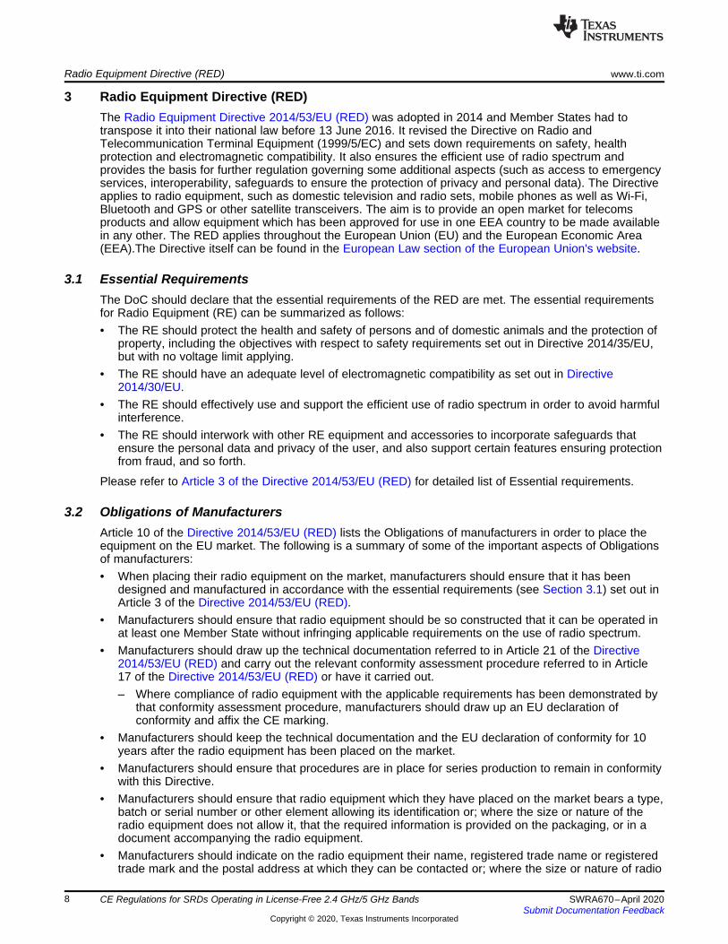
3.4 Restrictions on Putting into Service• If radio equipment is subject to restrictions on putting into service or to requirements for authorization
of use, as provided for in Article 10(10) of Directive 2014/53/EU, the packaging of the radio equipmentshould indicate visibly and legibly:– A pictogram, as set out in Annex I of Regulation (EU) 2017/1354; or– The words ‘Restrictions or Requirements in’, in a language easily understood by end-users as
determined by the Member State concerned, followed by the abbreviations of the Member States,as prescribed in Annex II of Regulation (EU) 2017/1354, where such restrictions or requirementsexist.
• If radio equipment is subject to restrictions on putting into service or to requirements for authorizationof use, as provided for in Article 10(10) of Directive 2014/53/EU, the instructions accompanying theradio equipment should indicate, in a language easily understood by end-users as determined by theMember State concerned, the list of the Member States and geographical areas within the MemberStates where such restrictions or requirements exist, as well as the types of restrictions orrequirements applicable in each Member State and each geographical area within a Member State.
The example of a pictogram is shown in Figure 1. Please refer to Annex I and Annex II of Regulation (EU)2017/1354 for complete details about pictogram.
ES LU RO
CZ FR HU
SI DK HR
www.ti.com Radio Equipment Directive (RED)
11SWRA670–April 2020Submit Documentation Feedback
Copyright © 2020, Texas Instruments Incorporated
CE Regulations for SRDs Operating in License-Free 2.4 GHz/5 GHz Bands
Figure 1. Pictogram Example

ETSI EN 300 440 www.ti.com
12 SWRA670–April 2020Submit Documentation Feedback
Copyright © 2020, Texas Instruments Incorporated
CE Regulations for SRDs Operating in License-Free 2.4 GHz/5 GHz Bands
4 ETSI EN 300 440The ETSI EN 300 440 is a Harmonized European standard which describes the performancerequirements and conformance test procedures for license exempt Short Range Devices (SRDs) intendingto use frequency bands within the range of 1 GHz to 40 GHz. The complete document can be downloadedfrom the ETSI website. The following is a summary of the most important requirements for Non-SpecificSRDs in the 2.4 GHz and 5 GHz bands in EN 300 440. The permitted frequency band limits for 2.4 GHzand 5 GHz bands are shown in Table 2.
Table 2. Limits on Permitted Frequency Bands in 2.4 GHz and 5 GHz Bands - EN 300 440
Mode of operation Frequency Band Applications
Transmit and Receive 2400 MHz to 2483.5 MHz Non-specific short rangedevices
Transmit and Receive 5725 MHz to 5875 MHz Non-specific short rangedevices
4.1 Technical RequirementsThe equipment should comply with all applicable technical requirements at all times when operating withinthe boundary limits of the operational environmental profile declared by the manufacturer. The technicalrequirements are shown in Table 3.
Table 3. Technical Requirements and Conditions - EN 300 440
Requirement Requirement Conditionality
No Description
EssentialRequiremen
ts ofDirective
2014/53/EUClause(s) of the
EN300 440 U/C (1) Condition
1 RF Output Power(e.i.r.p.) 3.2 4.2.2 C Applies to all devices with transmitters
2 Permitted range ofoperating frequencies 3.2 4.2.3 C Applies to all devices with transmitters
3 Unwanted emissions inthe spurious domain 3.2 4.2.4 C Applies to all devices with transmitters
4 Duty Cycle 3.2 4.2.5.4 C
Transmitting devices which do not useLBT, DAA, or RFID transmittersoperating in the 2446 to 2454 MHzband transmitting more than 500 mWe.i.r.p. power level
5 Additional requirementsfor FHSS equipment 3.2 4.2.6 C Equipment utilizing FHSS modulation
6 Adjacent channelselectivity 3.2 4.3.3 C Applies to equipment Category 1
receivers
7 Blocking orDesensitization 3.2 4.3.4 C Applies to category 1, 2, and 3 SRD
communication media receivers
8 Spurious radiation 3.2 4.3.5 C
Applies to all receivers, exceptreceivers used in combination withpermanently co-located transmitterscontinuously transmitting
9 Spectrum accesstechniques 3.2 4.4 C Equipment which are not using duty
cycle restrictions for media access10 GBSAR antenna pattern 3.2 4.6.4 C Applies only GBSAR systems11 Limits for GBSAR 3.2 Annex I C Applies only GBSAR systems
(1) U/C – Indicates whether the requirement is unconditionally applicable (U) or is conditional upon the manufacturer's claimedfunctionality of the equipment (C).

www.ti.com ETSI EN 300 440
13SWRA670–April 2020Submit Documentation Feedback
Copyright © 2020, Texas Instruments Incorporated
CE Regulations for SRDs Operating in License-Free 2.4 GHz/5 GHz Bands
4.1.1 Environmental ProfileThe environmental profile for operation of the equipment should be declared by the manufacturer. Theequipment should comply with all applicable technical requirements at all times when operating within theboundary limits of the declared operational environmental profile.
4.2 Transmitter RequirementsWhere the transmitter is designed with adjustable carrier power, then all transmitter parameters should bemeasured using the highest power level. The spurious emissions should be measured at both the highestand the lowest carrier power settings.
If the equipment to be tested is designed with a permanent external 50 Ω RF connector and a dedicatedor integral antenna, then full tests should be carried out using this connector. If the RF connector is not 50Ω, then a calibrated coupler or attenuator should be used to provide the correct termination impedance tofacilitate the measurements. The equivalent isotropically radiated power is then calculated from thedeclared antenna gain.
The following is a summary of the most important requirements for the transmitter in the 2.4 GHz and 5GHz bands in EN 300 440.
4.2.1 Transmitter Maximum Radiated Power (e.i.r.p.)The transmitter maximum radiated power (e.i.r.p) limits under normal and extreme test conditions areshown in the Table 4.
Table 4. Limits on TX Maximum Radiated Power (e.i.r.p.)
Entry Frequency Bands TX Power Application1 2400 MHz to 2483.5 MHz 10 mW e.i.r.p Non-specific short range devices5 5725 MHz to 5875 MHz 25 mW e.i.r.p Non-specific short range devices
4.2.2 Permitted Range of Operating FrequenciesThe permitted range of operating frequencies includes all frequencies on which the equipment mayoperate within an assigned frequency band. The operating frequency range should be declared by themanufacturer. The frequency range of the equipment is determined by the lowest and highest frequenciesoccupied by the power envelope, where the output power envelope drops below the level of –75 dBm/Hzspectral power density (or –30 dBm if measured in a 30 kHz bandwidth) e.i.r.p. Where differing modes ofemission are available, all modes and their associated bandwidths should be stated.
For all equipment the frequency range should lie within the frequency band specified in Table 4.
4.2.3 Unwanted Emissions in the Spurious DomainUnwanted emissions in the spurious domain (spurious emissions) are those at frequencies beyond thelimit of 250% of the occupied bandwidth above and below the center frequency of the emission. Theoccupied bandwidth is measured as declared by the manufacturer. Out-of-band and spurious emissionsare measured as spectral power density under normal operating conditions. The maximum power limits ofany unwanted emissions in the spurious domain are shown in Table 5.
Table 5. Limits on Spurious Emissions
Frequency Ranges 47-74 MHz87.5-118 MHz174-230 MHz470-862 MHz
Other frequenciesbelow 1000 MHz Frequencies Above 1000 MHzState
Operating 4nW = -54dBm 250nW = -36dBm 1μW = -30dBmStandby 2nW = -57dBm 2nW = -57dBm 20nW = -47dBm

ETSI EN 300 440 www.ti.com
14 SWRA670–April 2020Submit Documentation Feedback
Copyright © 2020, Texas Instruments Incorporated
CE Regulations for SRDs Operating in License-Free 2.4 GHz/5 GHz Bands
4.2.4 Duty CycleDuty cycle is defined as a ratio expressed as percentage of the cumulative duration of transmissions ONtime within a 1-hour observation period. Duty Cycle (DC) should apply to all transmitting equipment exceptthose which utilize Listen Before Talk (LBT) clause 4.4.2, or Detect And Avoid (DAA) clause 4.4.3. Thelimits for the maximum Duty Cycle within 1-hour observation period is shown in Table 6.
Table 6. Limits on Duty Cycle within 1-Hour Period
Frequency Band Duty Cycle Application2400 MHz to 2483.5 MHz No Restriction Generic use5725 MHz to 5875 MHz No Restriction Generic use
4.2.5 Additional Requirements for FHSS EquipmentEquipment employing FHSS (Frequency Hopping Spread Spectrum) should transmit over multiplechannels by moving its transmission frequency from channel. The requirements in this section apply onlyto equipment using FHSS modulation. The limits for FHSS are shown in Table 6.
Table 7. Limits on FHSS Modulation
Parameter Limits NotesNo of Channels > 20 Channels hopping over > 90% of assigned frequency band.
Dwell Time / Channel < 1 Sec.
While the equipment isoperating (transmitting and/orreceiving) each channel of thehopping sequence should be
occupied at least once during aperiod not exceeding four times
the product of the dwell timeper hop and the number of
channels.
4.3 Receiver RequirementsThe product family of short range radio devices is divided into three receiver categories (see Table 8)each having a set of relevant receiver requirements and minimum performance criteria. The set of receiverrequirements depends on the choice of receiver category by the equipment manufacturer.
4.3.1 Receiver CategoriesThe product family of short range radio devices is divided into three receiver categories, which are definedin Table 8. The manufacturer should specify the receiver category of their choice.
Table 8. Receiver Categories
Receiver Category Relevant Receiver Requirements Risk assessment of receiverperformance
1 (1) Refer to Section 4.3.3, Section 4.3.4 and Section 4.3.5
Highly reliable SRDcommunication media; for
example, serving human lifeinherent systems (may result in
a physical risk to a person.
2 (1), (2) Refer to Section 4.3.4 and Section 4.3.5
Medium reliability SRDcommunication media for
example, causinginconvenience to persons,
which cannot simply beovercome by other means.

www.ti.com ETSI EN 300 440
15SWRA670–April 2020Submit Documentation Feedback
Copyright © 2020, Texas Instruments Incorporated
CE Regulations for SRDs Operating in License-Free 2.4 GHz/5 GHz Bands
Table 8. Receiver Categories (continued)
Receiver Category Relevant Receiver Requirements Risk assessment of receiverperformance
3 Refer to Section 4.3.4 and Section 4.3.5
Standard reliability SRDcommunication media and
radiodetermination devices. forexample, Inconvenience to
persons, which can simply beovercome by other means (for
example, manual).
(1) Receiver Category 1 or 2 should be used for all equipment using LBT or DAA for interference mitigation.(2) Receiver category 2 may be required for specific spectrum access techniques are specified in Section 4.4.1.
4.3.2 Receiver Performance CriteriaFor the purpose of the receiver performance tests, the receiver should produce an appropriate outputunder normal conditions as indicated below:• A SND/ND ratio of 20 dB, measured at the receiver output through a telephone psophometric
weighting network as described in Recommendation ITU-T O.41; or• After demodulation, a data signal with a bit error ratio of 10-2 without correction; or• After demodulation, a message acceptance ratio of 80%; or• An appropriate false alarm rate or sensing criteria as declared by the manufacturer.
Unless otherwise specified, the measurements should be performed using normal operation of theequipment with the equipment operating in accordance, utilizing the worst-case configuration with regardsto the requirement to be tested. For each of the requirements in the present document, this worst-caseconfiguration should be declared by the manufacturer and documented in the test report to assure that theequipment is performing in accordance with its intended use. Special software or other alternativemethods may be used to operate the equipment in this mode.
4.3.3 Adjacent Channel SelectivityThe adjacent channel selectivity is a measure of the capability of the receiver to operate satisfactorily inthe presence of an unwanted signal that differs in frequency from the wanted signal by an amount equal tothe adjacent channel separation for which the equipment is intended. This requirement applies tochannelized Category 1 receivers only. The adjacent channel selectivity limits are shown in Table 9.
Table 9. Limits on Adjacent Channel Selectivity
Parameter Limit Performance Criteria
Adjacent Channel Level> (-30dBm + k),
Where, k=(-20*logf-10*logBW)k should be within the limits of -40 < k < 0dB
should meet the performancecriteria as specified in
Section 4.3.2f – is the frequeny in GHz
BW - is the channel bandwidth in MHz.
4.3.4 Blocking or DesensitizationBlocking is a measure of the capability of the receiver to receive a wanted modulated signal withoutexceeding a given degradation due to the presence of an unwanted input signal at any frequencies otherthan those of the spurious responses or the occupied bandwidth. This requirement applies to allCategories 1, 2 and 3 receivers. The adjacent channel selectivity limits are shown in the Table 10.

ETSI EN 300 440 www.ti.com
16 SWRA670–April 2020Submit Documentation Feedback
Copyright © 2020, Texas Instruments Incorporated
CE Regulations for SRDs Operating in License-Free 2.4 GHz/5 GHz Bands
Table 10. Limits on Blocking or Desensitization
Receiver Category Limit Performance Criteria
1> (-30dBm + k),
Where, k =(−20*logf −10*logBW)k should be within the limits of -40dB < k < 0dB should meet the performance
criteria as specified inSection 4.3.22 > (-45dBm + k)
3 > (-30dBm + k)f – is the frequeny in GHz
BW - is the channel bandwidth in MHz.
4.3.5 Spurious Radiations - ReceiverSpurious radiations from the receiver are components at any frequency, radiated by the equipment andantenna. The level of spurious radiations should be measured by either:• Their power level in a specified load (conducted spurious emission) and their effective radiated power
when radiated by the cabinet and structure of the equipment (cabinet radiation); or• Their effective radiated power when radiated by the cabinet and the integral or dedicated antenna, in
the case of portable equipment fitted with such an antenna and no permanent RF connector.
The power of any spurious emission should not exceed the limits shown in Table 11.
Table 11. Limits on Spurious Radiations - Receiver
Frequency Range Spurious Emission Level Limit25 MHz to 1 GHz < 2nW (-57dBm)>1GHz < 20nW (-47dBm)
4.4 Spectrum Access TechniquesFor equipment with radiated power of less than 100 μW e.i.r.p., no access technique is required. Thereare two mechanisms to access the spectrum:• Listen Before Talk (LBT), which is used to share spectrum between SRD transceiver equipment with
similar power and bandwidth; or• Detect And Avoid (DAA), which is used to protect radio communication services. This applies to 17.1
GHz to 17.3 GHz GBSAR only.
Receiver Category 2 or better should be used for all equipment using LBT or DAA.
Equipment utilizing LBT or DAA do not have to comply with the duty cycle conditions.
For spread spectrum systems, LBT may be used if the required timing and threshold limits can be met; ifnot, then a duty cycle requirement applies.
4.4.1 Listen Before TalkIn order to make maximum use of the available channels, intelligent or polite equipment may use a ListenBefore Talk (LBT) protocol with a preferred option of Adaptive Frequency Agility (AFA). AFA is defined asthe capability of equipment to dynamically change channel within its available frequencies for properoperation.
For LBT equipment, the device should listen on the next intended frequency before transmitting. If it isintended to move to a different channel then this channel can be monitored whilst still transmitting at itsfirst channel. If it is not intended to move to a different channel then it should be treated as a singlefrequency device waiting for a free channel.
4.4.1.1 LBT Timing ParamtersThe minimum Tx off-time is defined as the period where a specific transmitter should remain off after atransmission or a communication dialogue between units or a polling sequence of other units.

www.ti.com ETSI EN 300 440
17SWRA670–April 2020Submit Documentation Feedback
Copyright © 2020, Texas Instruments Incorporated
CE Regulations for SRDs Operating in License-Free 2.4 GHz/5 GHz Bands
The minimum listening time is defined as the minimum time that the equipment listens for a receivedsignal at or above the LBT threshold level (see Section 4.4.1.2) immediately prior to transmission todetermine whether the intended channel is available for use.
An acknowledge transmission is defined as a receipt for a received message.
For automatic operated LBT devices (either software controlled or pre-programmed devices), themanufacturer should declare all the channel LBT timings for the equipment under test.
For manual operated or event dependent devices (with or without software controlled functions), themanufacturer should declare whether the transmission, once triggered, follows a pre-programmed time-out-timer, or whether the transmitter remains on until the trigger is released or the device is manuallyreset.
The equipment with LBT should meet the LBT timing parameter limits shown in Table 12.
Table 12. Limits for LBT Timing Parameters
Parameter Limits NotesMinimum Tx Off-time >25 mSec
Minimum Listening time (tL) > (tF + tPS) mSec
tF = 5 mSec,
tPS should be randomly varied between 0 ms and a value of 5 ms or morein equal steps of approximately 0.5 ms as the following:
-If the channel is free from traffic at the beginning of the listen time, tL, andremains free throughout the fixed part of the listen time, tF, then the pseudorandom part, tPS, is automatically set to zero by the equipment itself.
- If the channel is occupied by traffic when the equipment either starts tolisten or during the listen period, then the listen time commences from theinstant that the intended channel is free. In this situation the total listen timetL should comprise tF and the pseudo random part, tPS.
Maximum Tx ON-time for aSingle Transmission < 2 Sec
Maximum Tx ON-time for aTransmission dialogue or a
polling sequence< 10 Sec In the case the time reaches the limit then the minimum Tx off-time limit
should apply automatically.
4.4.1.2 Receiver LBT Threshold and Transmitter Max On-TimeThe LBT threshold is defined as the received signal level above which the equipment can determine thatthe channel is not available for use. If the received signal is below the LBT threshold, then the equipmentcan determine that the channel is available for use.
The maximum LBT threshold limits for the receiver in listen mode are shown in Table 13. The limits for Txmax on-time is shown in Table 12.
Table 13. Limits for LBT Threshold Values Versus Transmit Power
Tx Power LBT Threshold Limit (1), (2) Notes< 100 mW -80 dBm + C C = 10*logBW, Where,
BW is the bandwidth in MHz.500 mW -87 dBm + C
(1) The limit is independent of the receiver category, see Section 4.3.1.(2) The limits are based on an antenna gain of +2 dBi maximum. For other antenna gains greater than +2 dBi the limits should be
adjusted accordingly.
4.4.2 Detect And Avoid Technique (DAA)DAA is specified for use with Ground Based Synthetic Aperture Radar (GBSAR) systems only. It providesprotection to other radio communication services. As GBSAR is not in the scope of this application note,DAA is not covered. Please refer to the standard ETSI EN 300 440 for details.
ETSI EN 300 328 www.ti.com
18 SWRA670–April 2020Submit Documentation Feedback
Copyright © 2020, Texas Instruments Incorporated
CE Regulations for SRDs Operating in License-Free 2.4 GHz/5 GHz Bands
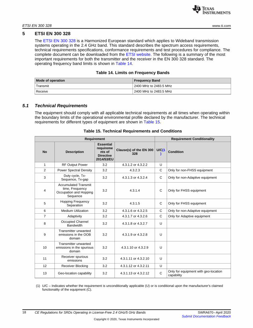
5 ETSI EN 300 328The ETSI EN 300 328 is a Harmonized European standard which applies to Wideband transmissionsystems operating in the 2.4 GHz band. This standard describes the spectrum access requirements,technical requirements specifications, conformance requirements and test procedures for compliance. Thecomplete document can be downloaded from the ETSI website. The following is a summary of the mostimportant requirements for both the transmitter and the receiver in the EN 300 328 standard. Theoperating frequency band limits is shown in Table 14.
Table 14. Limits on Frequency Bands
Mode of operation Frequency BandTransmit 2400 MHz to 2483.5 MHzReceive 2400 MHz to 2483.5 MHz
5.1 Technical RequirementsThe equipment should comply with all applicable technical requirements at all times when operating withinthe boundary limits of the operational environmental profile declared by the manufacturer. The technicalrequirements for different types of equipment are shown in Table 15.
Table 15. Technical Requirements and Conditions
Requirement Requirement Conditionality
No Description
Essentialrequireme
nts ofDirective
2014/53/EU
Clause(s) of the EN 300328
U/C(1) Condition
1 RF Output Power 3.2 4.3.1.2 or 4.3.2.2 U2 Power Spectral Density 3.2 4.3.2.3 C Only for non-FHSS equipment
3 Duty cycle, Tx-Sequence, Tx-gap 3.2 4.3.1.3 or 4.3.2.4 C Only for non-Adaptive equipment
4
Accumulated Transmittime, Frequency
Occupation and HoppingSequence
3.2 4.3.1.4 C Only for FHSS equipment
5 Hopping FrequencySeparation 3.2 4.3.1.5 C Only for FHSS equipment
6 Medium Utilization 3.2 4.3.1.6 or 4.3.2.5 C Only for non-Adaptive equipment7 Adaptivity 3.2 4.3.1.7 or 4.3.2.6 C Only for Adaptive equipment
8 Occupied ChannelBandwidth 3.2 4.3.1.8 or 4.3.2.7 U
9Transmitter unwantedemissions in the OOB
domain3.2 4.3.1.9 or 4.3.2.8 U
10Transmitter unwanted
emissions in the spuriousdomain
3.2 4.3.1.10 or 4.3.2.9 U
11 Receiver spuriousemissions 3.2 4.3.1.11 or 4.3.2.10 U
12 Receiver Blocking 3.2 4.3.1.12 or 4.3.2.11 U
13 Geo-location capability 3.2 4.3.1.13 or 4.3.2.12 C Only for equipment with geo-locationcapability
(1) U/C – Indicates whether the requirement is unconditionally applicable (U) or is conditional upon the manufacturer's claimedfunctionality of the equipment (C).

www.ti.com ETSI EN 300 328
19SWRA670–April 2020Submit Documentation Feedback
Copyright © 2020, Texas Instruments Incorporated
CE Regulations for SRDs Operating in License-Free 2.4 GHz/5 GHz Bands
5.1.1 Environmental ProfileThe environmental profile for operation of the equipment should be declared by the manufacturer. Theequipment should comply with all applicable technical requirements at all times when operating within theboundary limits of the declared operational environmental profile.
5.2 Equipment TypesThe standard covers the following equipment.• Wideband Data transmission equipment.• Adaptive and Non-adaptive equipment• Receiver categories• Antenna types
5.2.1 Wideband Data Transmission Equipment TypesThere are two categories of the Wideband Data Transmission equipment. They are:• Frequency Hopping Spread Spectrum (FHSS) equipment.• Other types of Wideband Data Transmission (Non-FHSS) equipment, (for example, DSSS, OFDM, and
so forth).
The equipment categories should be declared by the manufacturer.
5.2.2 Adaptive and Non-Adaptive EquipmentAdaptive equipment can use an automatic mechanism which allows the equipment to adapt to its radioenvironment by identifying other transmissions on the operating frequency. Adaptive equipment may havemore than one adaptive mode implemented. Adaptive equipment is allowed to operate in a non-adaptivemode. Equipment is allowed to switch between any of these modes.
Non-adaptive equipment does not use such an automatic mechanism and hence is subject to certainrestrictions with respect to using the medium (for more information, see Table 6) in order to ensuresharing with other equipment.
Unless otherwise specified, the equipment should comply with the corresponding requirements (Table 6)in each of the modes in which it can operate.
The manufacturer should declare whether the equipment is adaptive equipment or non-adaptiveequipment. In case of adaptive equipment, the manufacturer should declare all adaptive modes in additionto whether the equipment can also operate in a non-adaptive mode.
5.2.3 Receiver CategoriesThe receivers are divided into three different categories based on their modes of operation. They are:• Receiver category 1 – the equipment which operates as Adaptive equipment with a maximum RF
output power greater than 10 dBm e.i.r.p.• Receiver category 2 – the equipment which operates as non-adaptive equipment with a Medium
Utilization (MU) factor greater than 1% and less than or equal to 10% (irrespective of the maximum RFoutput power) or equipment (adaptive or non-adaptive) with a maximum RF output power greater than0 dBm e.i.r.p. and less than or equal to 10 dBm e.i.r.p.
• Receiver category 3 – non-adaptive equipment with a maximum Medium Utilization (MU) factor of 1%(irrespective of the maximum RF output power) or equipment (adaptive or non-adaptive) with amaximum RF output power of 0 dBm e.i.r.p.
Different receiver requirements and/or corresponding limits apply based on the category of the receiver.
5.2.4 Antenna TypesThere are two types of antenna. They are:• Integral antenna
ETSI EN 300 328 www.ti.com
20 SWRA670–April 2020Submit Documentation Feedback
Copyright © 2020, Texas Instruments Incorporated
CE Regulations for SRDs Operating in License-Free 2.4 GHz/5 GHz Bands
• Dedicated antenna
The equipment should have either type of the antenna.
5.3 Conformance RequirementsThe Conformance requirements are different for different type of equipment. Basically they are classifiedinto two types of categories. They are:• Frequency Hopping equipment (both Adaptive and Non-adaptive types)• Wideband Data Transmission equipment (Non – FHSS equipment)
The conformance requirements for both the equipment types are covered in the following sub-sections.
5.3.1 Conformance Requirements for Frequency Hopping EquipmentThe Conformance requirements for Frequency Hopping equipment (both Adaptive and Non-adaptivetypes) are covered in the following sub-sections.
5.3.1.1 RF Output PowerThe RF output power is defined as the mean equivalent isotropic radiated power (e.i.r.p.) of the equipmentduring a transmission burst. The RF output power (e.i.r.p) limits are shown in the Table 16.
Table 16. Limits on RF Output Power
Equipment type RF Output Power (e.i.r.p) NotesFHSS (Frequency Hopping) equipment < = 20 dBmNon-adaptive FHSS (Frequency Hopping)equipment
< = Manufacturer declared value Where the Manufacturer declare the valueof < 20 dBm
5.3.1.2 Duty CycleDuty Cycle is defined as the ratio of the total transmitter 'on'-time to an observation period. Theobservation period is equal to:• The average dwell time multiplied by 100; or• The average dwell time multiplied by 2 times the number of hopping frequencies (N); whichever is the
greater.
Tx-sequence is defined as a period in time during which a single or multiple transmissions may occur andwhich is followed by a Tx-gap. These multiple transmissions within a single Tx-sequence may take placeon the same hopping frequency or on multiple hopping frequencies. Tx-gap is defined as a period in timeduring which no transmissions occur on any of the hopping frequencies.
Duty cycle limit applies to non-adaptive FHSS equipment only.
Duty cycle limit doesn’t apply for equipment with a declared RF Output power of less than 10 dBm e.i.r.p.or for equipment when operating in a mode where the RF Output power is less than 10 dBm e.i.r.p.
The Duty cycle must be declared by the manufacturer and should be in compliance with the limitsmentioned in Table 8. The Duty Cycle limits are shown in the Table 17.
Table 17. Limits on Duty Cycle
Equipment type RF Output Power (e.i.r.p) LimitsFHSS (Frequency Hopping)
equipment (adaptive or non-adaptive) < 10 dBm Doesn’t Apply
Non-adaptive FHSS (FrequencyHopping) equipment > = 10 dBm
<= Maximum value declared by theManufacturer
Maximum Tx-sequence time < = 5 ms.
Minimum Tx-gap time <= 5 ms
www.ti.com ETSI EN 300 328
21SWRA670–April 2020Submit Documentation Feedback
Copyright © 2020, Texas Instruments Incorporated
CE Regulations for SRDs Operating in License-Free 2.4 GHz/5 GHz Bands
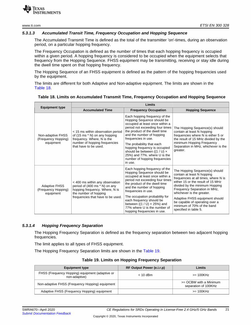
5.3.1.3 Accumulated Transit Time, Frequency Occupation and Hopping SequenceThe Accumulated Transmit Time is defined as the total of the transmitter 'on'-times, during an observationperiod, on a particular hopping frequency.
The Frequency Occupation is defined as the number of times that each hopping frequency is occupiedwithin a given period. A hopping frequency is considered to be occupied when the equipment selects thatfrequency from the Hopping Sequence. FHSS equipment may be transmitting, receiving or stay idle duringthe dwell time spent on that hopping frequency.
The Hopping Sequence of an FHSS equipment is defined as the pattern of the hopping frequencies usedby the equipment.
The limits are different for both Adaptive and Non-adaptive equipment. The limits are shown in theTable 18.
Table 18. Limits on Accumulated Transmit Time, Frequency Occupation and Hopping Sequence
Equipment typeLimits
Accumulated Time Frequency Occupation Hopping Sequence
Non-adaptive FHSS(Frequency Hopping)
equipment
< 15 ms within observation periodof (15 ms * N) on any hoppingfrequency. Where, N is thenumber of hopping frequenciesthat have to be used.
Each hopping frequency of theHopping Sequence should beoccupied at least once within aperiod not exceeding four timesthe product of the dwell timeand the number of hoppingfrequencies in use.
The probability that eachhopping frequency is occupiedshould be between ((1 / U) ×25%) and 77%. where U is thenumber of hopping frequenciesin use.
The Hopping Sequence(s) shouldcontain at least N hoppingfrequencies where N is either 5 orthe result of 15 MHz divided by theminimum Hopping FrequencySeparation in MHz, whichever is thegreater.
Adaptive FHSS(Frequency Hopping)
equipment
< 400 ms within any observationperiod of (400 ms * N) on anyhopping frequency. Where, N isthe number of hoppingfrequencies that have to be used.
Each hopping frequency of theHopping Sequence should beoccupied at least once within aperiod not exceeding four timesthe product of the dwell timeand the number of hoppingfrequencies in use.
The occupation probability foreach frequency should bebetween ((1 / U) × 25%) and77% where U is the number ofhopping frequencies in use.
The Hopping Sequence(s) shouldcontain at least N hoppingfrequencies at all times, where N iseither 15 or the result of 15 MHzdivided by the minimum HoppingFrequency Separation in MHz,whichever is the greater.
Adaptive FHSS equipment shouldbe capable of operating over aminimum of 70% of the bandspecified in table 5.
5.3.1.4 Hopping Frequency SeparationThe Hopping Frequency Separation is defined as the frequency separation between two adjacent hoppingfrequencies.
The limit applies to all types of FHSS equipment.
The Hopping Frequency Separation limits are shown in the Table 19.
Table 19. Limits on Hopping Frequency Separation
Equipment type RF Output Power (e.i.r.p) LimitsFHSS (Frequency Hopping) equipment (adaptive or
non-adaptive) < 10 dBm >= 100KHz
Non-adaptive FHSS (Frequency Hopping) equipment >= OCBW with a Minimumseparation of 100KHz
Adaptive FHSS (Frequency Hopping) equipment >= 100KHz
ETSI EN 300 328 www.ti.com
22 SWRA670–April 2020Submit Documentation Feedback
Copyright © 2020, Texas Instruments Incorporated
CE Regulations for SRDs Operating in License-Free 2.4 GHz/5 GHz Bands
5.3.1.5 Medium Utilization (MU) FactorThe Medium Utilization (MU) factor is defined as a measure to quantify the amount of resources (Powerand Time) used by non-adaptive equipment. The Medium Utilization factor is defined by the formula:
MU = (Pout/ 100 mW) x DC (1)
Where,
MU is Medium Utilization factor in %.Pout is the RF output power in mW.DC is the Duty Cycle in %.
The limit doesn’t apply to adaptive FHSS equipment unless operating in a non-adaptive mode. Themaximum Medium Utilization factor limits are shown in the Table 20.
Table 20. Limits on Medium Utilization Factor
Equipment Type RF Output Power (e.i.r.p) LimitsFHSS (Frequency Hopping) equipment (adaptive or non-
adaptive) < 10 dBm Doesn’t Apply
Adaptive FHSS (Frequency Hopping) equipment Doesn’t ApplyNon-adaptive FHSS (Frequency Hopping) equipment <= 10%
5.3.1.6 Adaptivity (Adaptive FHSS)The adaptive FHSS equipment is defined as equipment using a mechanism which allows it to adapt to itsradio environment by identifying frequencies that are being used by other equipment. The adaptivefrequency hopping mechanism is a method that allows FHSS equipment to adapt to its radio environmentby identifying channels that are being used and excluding them from the list of available channels. Thereare two mechanisms in Adaptive FHSS, which are LBT (Listen-Before-Talk) and DAA (Detect And Avoid).Adaptive FHSS equipment should implement either of the mechanisms (LBT or DAA) and it is allowed toswitch dynamically in between the two adaptive modes.
Adaptive FHSS equipment is allowed to have Short Control Signaling Transmissions without sensing thefrequency for the presence of other signals.
The limit does not apply to non-adaptive FHSS equipment or adaptive equipment operating in a non-adaptive mode. In addition, this requirement does not apply for FHSS equipment with a maximumdeclared RF Output power level of less than 10 dBm e.i.r.p. or for FHSS equipment when operating in amode where the RF Output power is less than 10 dBm e.i.r.p.
The Adaptive FHSS limits are shown in the Table 21.
Table 21. Limits on FHSS Equipment
Equipment Type RF Output Power (e.i.r.p) LimitsFHSS (Frequency Hopping) equipment (adaptive or non-
adaptive) < 10 dBm Doesn’t Apply
Non-adaptive FHSS (Frequency Hopping) equipment Doesn’t ApplyAdaptive FHSS (Frequency Hopping) equipment - LBT Please refer to Section 5.3.1.6.1Adaptive FHSS (Frequency Hopping) equipment - DAA Please refer to Section 5.3.1.6.2
www.ti.com ETSI EN 300 328
23SWRA670–April 2020Submit Documentation Feedback
Copyright © 2020, Texas Instruments Incorporated
CE Regulations for SRDs Operating in License-Free 2.4 GHz/5 GHz Bands
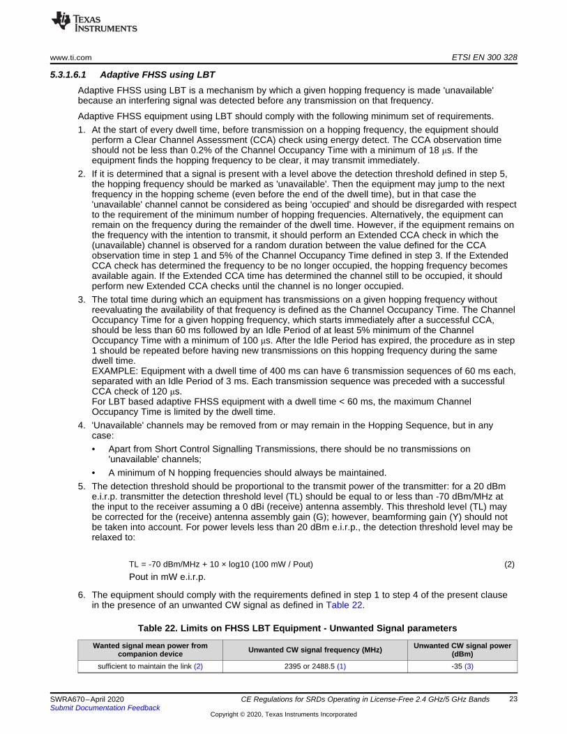
5.3.1.6.1 Adaptive FHSS using LBTAdaptive FHSS using LBT is a mechanism by which a given hopping frequency is made 'unavailable'because an interfering signal was detected before any transmission on that frequency.
Adaptive FHSS equipment using LBT should comply with the following minimum set of requirements.1. At the start of every dwell time, before transmission on a hopping frequency, the equipment should
perform a Clear Channel Assessment (CCA) check using energy detect. The CCA observation timeshould not be less than 0.2% of the Channel Occupancy Time with a minimum of 18 μs. If theequipment finds the hopping frequency to be clear, it may transmit immediately.
2. If it is determined that a signal is present with a level above the detection threshold defined in step 5,the hopping frequency should be marked as 'unavailable'. Then the equipment may jump to the nextfrequency in the hopping scheme (even before the end of the dwell time), but in that case the'unavailable' channel cannot be considered as being 'occupied' and should be disregarded with respectto the requirement of the minimum number of hopping frequencies. Alternatively, the equipment canremain on the frequency during the remainder of the dwell time. However, if the equipment remains onthe frequency with the intention to transmit, it should perform an Extended CCA check in which the(unavailable) channel is observed for a random duration between the value defined for the CCAobservation time in step 1 and 5% of the Channel Occupancy Time defined in step 3. If the ExtendedCCA check has determined the frequency to be no longer occupied, the hopping frequency becomesavailable again. If the Extended CCA time has determined the channel still to be occupied, it shouldperform new Extended CCA checks until the channel is no longer occupied.
3. The total time during which an equipment has transmissions on a given hopping frequency withoutreevaluating the availability of that frequency is defined as the Channel Occupancy Time. The ChannelOccupancy Time for a given hopping frequency, which starts immediately after a successful CCA,should be less than 60 ms followed by an Idle Period of at least 5% minimum of the ChannelOccupancy Time with a minimum of 100 μs. After the Idle Period has expired, the procedure as in step1 should be repeated before having new transmissions on this hopping frequency during the samedwell time.EXAMPLE: Equipment with a dwell time of 400 ms can have 6 transmission sequences of 60 ms each,separated with an Idle Period of 3 ms. Each transmission sequence was preceded with a successfulCCA check of 120 μs.For LBT based adaptive FHSS equipment with a dwell time < 60 ms, the maximum ChannelOccupancy Time is limited by the dwell time.
4. 'Unavailable' channels may be removed from or may remain in the Hopping Sequence, but in anycase:• Apart from Short Control Signalling Transmissions, there should be no transmissions on
'unavailable' channels;• A minimum of N hopping frequencies should always be maintained.
5. The detection threshold should be proportional to the transmit power of the transmitter: for a 20 dBme.i.r.p. transmitter the detection threshold level (TL) should be equal to or less than -70 dBm/MHz atthe input to the receiver assuming a 0 dBi (receive) antenna assembly. This threshold level (TL) maybe corrected for the (receive) antenna assembly gain (G); however, beamforming gain (Y) should notbe taken into account. For power levels less than 20 dBm e.i.r.p., the detection threshold level may berelaxed to:
TL = -70 dBm/MHz + 10 × log10 (100 mW / Pout) (2)Pout in mW e.i.r.p.
6. The equipment should comply with the requirements defined in step 1 to step 4 of the present clausein the presence of an unwanted CW signal as defined in Table 22.
Table 22. Limits on FHSS LBT Equipment - Unwanted Signal parameters
Wanted signal mean power fromcompanion device Unwanted CW signal frequency (MHz) Unwanted CW signal power
(dBm)sufficient to maintain the link (2) 2395 or 2488.5 (1) -35 (3)

ETSI EN 300 328 www.ti.com
24 SWRA670–April 2020Submit Documentation Feedback
Copyright © 2020, Texas Instruments Incorporated
CE Regulations for SRDs Operating in License-Free 2.4 GHz/5 GHz Bands
(1) The highest frequency should be used for testing operating channels within the range 2400 MHz to 2442 MHz, while the lowestfrequency should be used for testing operating channels within the range 2442 MHz to 2483.5 MHz.
(2) A typical conducted value which can be used in most cases is -50 dBm/MHz.(3) The level specified is the level at the UUT receiver input assuming a 0 dBi antenna assembly gain. In case of conducted
measurements, this level has to be corrected for the (in-band) antenna assembly gain (G). In case of radiated measurements,this level is equivalent to a power flux density (PFD) in front of the UUT antenna.
5.3.1.6.2 Adaptive FHSS Using DAAAdaptive FHSS using Detect And Avoid (DAA) is a mechanism by which a given hopping frequency ismade 'unavailable' because an interfering signal was reported after transmissions on that frequency. Thismechanism should operate as intended in the presence of an unwanted signal on frequencies other thanthose of the operating band.
Adaptive FHSS equipment using DAA should comply with the following minimum set of requirements.• During normal operation, the equipment should evaluate the presence of a signal for each of its
hopping frequencies. If it is determined that a signal is present with a level above the detectionthreshold defined in step 5, the hopping frequency should be marked as 'unavailable'.
• The hopping frequency should remain unavailable for a minimum time equal to 1 second or 5 times theactual number of hopping frequencies in the current (adapted) channel map used by the equipment,multiplied with the Channel Occupancy Time, whichever is greater. There should be no transmissionsduring this silent period on this hopping frequency. After this, the hopping frequency may beconsidered again as an 'available' frequency.
• The total time during which an equipment has transmissions on a given hopping frequency without re-evaluating the availability of that hopping frequency is defined as the Channel Occupancy Time. TheChannel Occupancy Time for a given hopping frequency should be less than 40 ms. For equipmentusing a dwell time > 40 ms that wants to have other transmissions during the same hop (dwell time),an Idle Period (no transmissions) of at least 5% minimum of the Channel Occupancy Period with aminimum of 100 μs should be implemented. After the Idle Period has expired, the equipment maycontinue its normal operation as explained in step 1.Example: An equipment with a dwell time of 400 ms can have 9 transmission sequences of 40 mseach, separated with an Idle Period of 2 ms.For FHSS equipment using DAA with a dwell time < 40 ms, the maximum Channel Occupancy Timemay be non-contiguous; in other words, spread over a number of Hopping Sequences (equal to 40 msdivided by the dwell time [ms]).
• In case the 'unavailable' channels remain in the Hopping Sequence, apart from the Short ControlSignalling Transmissions, there should be no transmissions on these 'unavailable' channels. In casethe 'unavailable channels' are removed from the Hopping Sequence, a minimum of N hoppingfrequencies should always be maintained.
• The detection threshold should be proportional to the transmit power of the transmitter: for a 20 dBme.i.r.p. transmitter the detection threshold level (TL) should be equal to or less than -70 dBm/MHz atthe input to the receiver, assuming a 0 dBi (receive) antenna assembly. This threshold level (TL) maybe corrected for the (receive) antenna assembly gain (G); however, beamforming gain (Y) should notbe taken into account. For power levels less than 20 dBm e.i.r.p., the detection threshold level may berelaxed to:
TL = -70 dBm/MHz + 10 × log10 (100 mW / Pout) (3)Pout in mW e.i.r.p.
• The equipment should comply with the requirements defined in step 1 to step 4 of the present clausein the presence of an unwanted CW signal as defined in Table 23.
Table 23. Limits on Adaptive FHSS DAA Equipment - Unwanted Signal parameters
Wanted signal mean powerfrom companion device
(dBm)Unwanted CW signal frequency (MHz) Unwanted CW signal power
(dBm)
-30 (2) 2395 or 2488.5 (1) -35 (3)

www.ti.com ETSI EN 300 328
25SWRA670–April 2020Submit Documentation Feedback
Copyright © 2020, Texas Instruments Incorporated
CE Regulations for SRDs Operating in License-Free 2.4 GHz/5 GHz Bands
(1) The highest frequency should be used for testing operating channels within the range 2400 MHz to 2442 MHz, while the lowestfrequency should be used for testing operating channels within the range 2442 MHz to 2483.5 MHz.
(2) The level specified is the level at the UUT receiver input assuming a 0 dBi antenna assembly gain. In case of conductedmeasurements, this level has to be corrected for the (in-band) antenna assembly gain (G). In case of radiated measurements,this level is equivalent to a power flux density in front of the UUT antenna.
5.3.1.6.3 Adaptive FHSSS - Short Control Signaling TransmissionsShort Control Signalling Transmissions are transmissions used by Adaptive FHSS equipment to sendmanagement and control signals without sensing the hopping frequency for the presence of other signals.Adaptive equipment may have Short Control Signalling Transmissions.
Short Control Signalling Transmissions should have a maximum limit of TxOn / (TxOn + TxOff), ratio of10% within any observation period of 50 ms or within an observation period equal to the dwell time,whichever is less.
5.3.1.7 Occupied Channel BandwidthThe Occupied Channel Bandwidth is defined as the bandwidth that contains 99% of the power of thesignal when considering a single hopping frequency.
The limits apply to all types of FHSS equipment. The limits are shown in Table 24.
Table 24. Limits on Occupied Channel Bandwidth
Equipment type RF Output Power (e.i.r.p) LimitsFHSS (Frequency Hopping) equipment (adaptive
or non-adaptive)OCBW should be within the Frequency
band of 2400 MHz to 2483.5 MHzNon-adaptive FHSS (Frequency Hopping)
equipment < 10 dBm OCBW < = 5 MHz
5.3.1.8 Transmitter Unwanted Emissions in the Out-of-Band DomainTransmitter unwanted emissions in the out-of-band domain are defined as emissions on frequenciesimmediately outside the allocated band, but excluding unwanted emissions in the spurious domain, whenthe equipment is in Transmit mode.
The limits apply to all types of FHSS equipment. The limits for unwanted emissions in the out-of-band-domain are shown in Table 25.
Table 25. Limits on Transmitter Unwanted Emissions in Out-Of-Band (OOB) domain
OOB Band (Frequency Range) (1) Limits (Emission level in e.i.r.p)
From (2400 MHz – BW) to 2400 MHzFrom 2483.5 MHz to (2483.5 MHz + BW )
< -10 dBm/MHz
From (2400 MHz – 2*BW) to (2400 MHz – BW)From (2483.5 MHz + BW) to (2483.5 MHz + 2*BW )
< -20 dBm/MHz
From <(2400 MHz - 2*BW) to 2400 - 2*BWFrom >(2483.5 MHz + 2*BW) to (2483.5 MHz + 2*BW)
Refer to spurious domain limits
(1) BW = OCBW in MHz or 1 MHz whichever is greater
5.3.1.9 Transmitter Unwanted Emissions in the Spurious DomainTransmitter unwanted emissions in the spurious domain are defined as emissions outside the allocatedband and outside the out-of-band domain as shown in Table 16, when the equipment is in Transmit mode.
The limits apply to all types of FHSS equipment. The limits for unwanted emissions in the spurious domainare shown in Table 26.
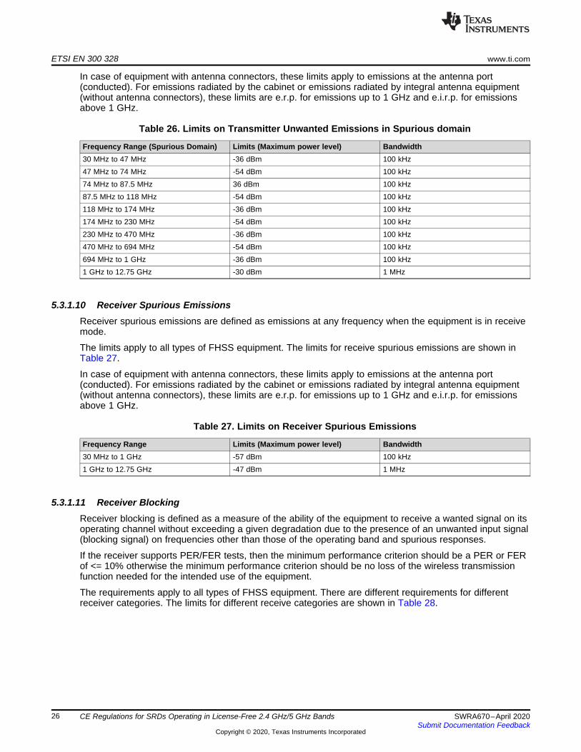
ETSI EN 300 328 www.ti.com
26 SWRA670–April 2020Submit Documentation Feedback
Copyright © 2020, Texas Instruments Incorporated
CE Regulations for SRDs Operating in License-Free 2.4 GHz/5 GHz Bands
In case of equipment with antenna connectors, these limits apply to emissions at the antenna port(conducted). For emissions radiated by the cabinet or emissions radiated by integral antenna equipment(without antenna connectors), these limits are e.r.p. for emissions up to 1 GHz and e.i.r.p. for emissionsabove 1 GHz.
Table 26. Limits on Transmitter Unwanted Emissions in Spurious domain
Frequency Range (Spurious Domain) Limits (Maximum power level) Bandwidth30 MHz to 47 MHz -36 dBm 100 kHz47 MHz to 74 MHz -54 dBm 100 kHz74 MHz to 87.5 MHz 36 dBm 100 kHz87.5 MHz to 118 MHz -54 dBm 100 kHz118 MHz to 174 MHz -36 dBm 100 kHz174 MHz to 230 MHz -54 dBm 100 kHz230 MHz to 470 MHz -36 dBm 100 kHz470 MHz to 694 MHz -54 dBm 100 kHz694 MHz to 1 GHz -36 dBm 100 kHz1 GHz to 12.75 GHz -30 dBm 1 MHz
5.3.1.10 Receiver Spurious EmissionsReceiver spurious emissions are defined as emissions at any frequency when the equipment is in receivemode.
The limits apply to all types of FHSS equipment. The limits for receive spurious emissions are shown inTable 27.
In case of equipment with antenna connectors, these limits apply to emissions at the antenna port(conducted). For emissions radiated by the cabinet or emissions radiated by integral antenna equipment(without antenna connectors), these limits are e.r.p. for emissions up to 1 GHz and e.i.r.p. for emissionsabove 1 GHz.
Table 27. Limits on Receiver Spurious Emissions
Frequency Range Limits (Maximum power level) Bandwidth30 MHz to 1 GHz -57 dBm 100 kHz1 GHz to 12.75 GHz -47 dBm 1 MHz
5.3.1.11 Receiver BlockingReceiver blocking is defined as a measure of the ability of the equipment to receive a wanted signal on itsoperating channel without exceeding a given degradation due to the presence of an unwanted input signal(blocking signal) on frequencies other than those of the operating band and spurious responses.
If the receiver supports PER/FER tests, then the minimum performance criterion should be a PER or FERof <= 10% otherwise the minimum performance criterion should be no loss of the wireless transmissionfunction needed for the intended use of the equipment.
The requirements apply to all types of FHSS equipment. There are different requirements for differentreceiver categories. The limits for different receive categories are shown in Table 28.

www.ti.com ETSI EN 300 328
27SWRA670–April 2020Submit Documentation Feedback
Copyright © 2020, Texas Instruments Incorporated
CE Regulations for SRDs Operating in License-Free 2.4 GHz/5 GHz Bands
Table 28. Limits on Receiver Blocking (All Categories)
ReceiverCategory
Wanted signal mean powerfrom companion device
(dBm) (1),(4)
Blockingsignal
frequency(MHz)
Blocking signal power (dBm)(4) Type of blocking signal
1
(-133 dBm + 10 ×log10(OCBW)) or -68 dBm
whichever is less (2)
2380
>=-34 CW
2504
(-139 dBm + 10 ×log10(OCBW)) or -74 dBm
whichever is less (3)
230023302360252425842674
2
(-139 dBm + 10 ×log10(OCBW) + 10 dB) or (-74
dBm + 10 dB) whichever isless (5)
2380
>=-34 CW250423002584
3
(-139 dBm + 10 ×log10(OCBW) + 20 dB) or (-74
dBm + 20 dB) whichever isless (6)
2380
>=-34 CW250423002584
(1) OCBW is in Hz.(2) In case of radiated measurements using a companion device and the level of the wanted signal from the companion device
cannot be determined, a relative test may be performed using a wanted signal up to Pmin + 26 dB where Pmin is the minimumlevel of wanted signal required to meet the minimum performance criteria as defined in this section in the absence of anyblocking signal.
(3) In case of radiated measurements using a companion device and the level of the wanted signal from the companion devicecannot be determined, a relative test may be performed using a wanted signal up to Pmin + 20 dB where Pmin is the minimumlevel of wanted signal required to meet the minimum performance criteria as defined in in this section in the absence of anyblocking signal.
(4) The level specified is the level at the UUT receiver input assuming a 0 dBi antenna assembly gain. In case of conductedmeasurements, this level has to be corrected for the (in-band) antenna assembly gain (G). In case of radiated measurements,this level is equivalent to a power flux density (PFD) in front of the UUT antenna with the UUT being configured/positioned formaximum e.i.r.p. towards the measuring antenna.
(5) In case of radiated measurements using a companion device and the level of the wanted signal from the companion devicecannot be determined, a relative test may be performed using a wanted signal up to Pmin + 26 dB where Pmin is the minimumlevel of wanted signal required to meet the minimum performance criteria as defined in this section in the absence of anyblocking signal.
(6) In case of radiated measurements using a companion device and the level of the wanted signal from the companion devicecannot be determined, a relative test may be performed using a wanted signal up to Pmin + 30 dB where Pmin is the minimumlevel of wanted signal required to meet the minimum performance criteria as defined in this section in the absence of anyblocking signal.
5.3.1.12 Geo-Location CapabilityGeo-location capability is a feature of the equipment to determine its geographical location with thepurpose to configure itself according to the regulatory requirements applicable at the geographical locationwhere it operates.
The geo-location capability may be present in the equipment or in an external device (temporary)associated with the equipment operating at the same geographical location during the initial power up ofthe equipment. The geographical location may also be available in equipment already installed andoperating at the same geographical location.
The requirement only applies to FHSS equipment with geo-location capability. The geographical locationdetermined by the FHSS equipment should not be accessible to the user in a way that would allow theuser to alter it.
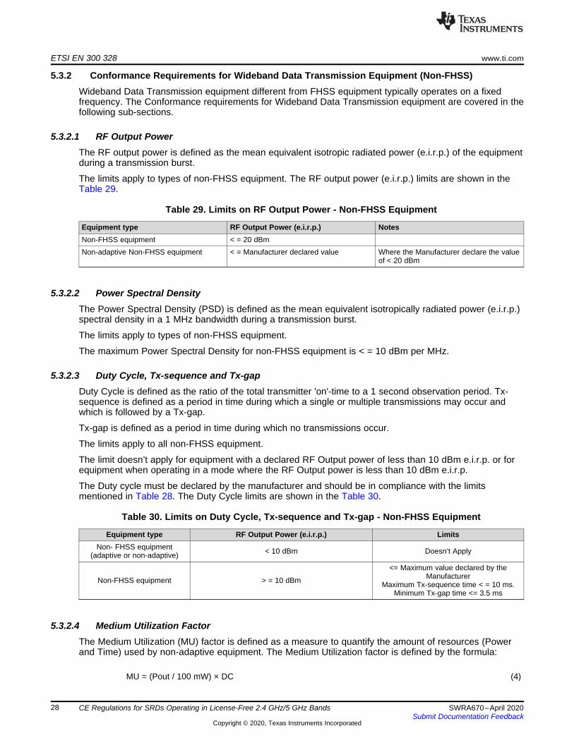
ETSI EN 300 328 www.ti.com
28 SWRA670–April 2020Submit Documentation Feedback
Copyright © 2020, Texas Instruments Incorporated
CE Regulations for SRDs Operating in License-Free 2.4 GHz/5 GHz Bands
5.3.2 Conformance Requirements for Wideband Data Transmission Equipment (Non-FHSS)Wideband Data Transmission equipment different from FHSS equipment typically operates on a fixedfrequency. The Conformance requirements for Wideband Data Transmission equipment are covered in thefollowing sub-sections.
5.3.2.1 RF Output PowerThe RF output power is defined as the mean equivalent isotropic radiated power (e.i.r.p.) of the equipmentduring a transmission burst.
The limits apply to types of non-FHSS equipment. The RF output power (e.i.r.p.) limits are shown in theTable 29.
Table 29. Limits on RF Output Power - Non-FHSS Equipment
Equipment type RF Output Power (e.i.r.p.) NotesNon-FHSS equipment < = 20 dBmNon-adaptive Non-FHSS equipment < = Manufacturer declared value Where the Manufacturer declare the value
of < 20 dBm
5.3.2.2 Power Spectral DensityThe Power Spectral Density (PSD) is defined as the mean equivalent isotropically radiated power (e.i.r.p.)spectral density in a 1 MHz bandwidth during a transmission burst.
The limits apply to types of non-FHSS equipment.
The maximum Power Spectral Density for non-FHSS equipment is < = 10 dBm per MHz.
5.3.2.3 Duty Cycle, Tx-sequence and Tx-gapDuty Cycle is defined as the ratio of the total transmitter 'on'-time to a 1 second observation period. Tx-sequence is defined as a period in time during which a single or multiple transmissions may occur andwhich is followed by a Tx-gap.
Tx-gap is defined as a period in time during which no transmissions occur.
The limits apply to all non-FHSS equipment.
The limit doesn’t apply for equipment with a declared RF Output power of less than 10 dBm e.i.r.p. or forequipment when operating in a mode where the RF Output power is less than 10 dBm e.i.r.p.
The Duty cycle must be declared by the manufacturer and should be in compliance with the limitsmentioned in Table 28. The Duty Cycle limits are shown in the Table 30.
Table 30. Limits on Duty Cycle, Tx-sequence and Tx-gap - Non-FHSS Equipment
Equipment type RF Output Power (e.i.r.p.) LimitsNon- FHSS equipment
(adaptive or non-adaptive) < 10 dBm Doesn’t Apply
Non-FHSS equipment > = 10 dBm
<= Maximum value declared by theManufacturer
Maximum Tx-sequence time < = 10 ms.Minimum Tx-gap time <= 3.5 ms
5.3.2.4 Medium Utilization FactorThe Medium Utilization (MU) factor is defined as a measure to quantify the amount of resources (Powerand Time) used by non-adaptive equipment. The Medium Utilization factor is defined by the formula:
MU = (Pout / 100 mW) × DC (4)

www.ti.com ETSI EN 300 328
29SWRA670–April 2020Submit Documentation Feedback
Copyright © 2020, Texas Instruments Incorporated
CE Regulations for SRDs Operating in License-Free 2.4 GHz/5 GHz Bands
Where,
MU is Medium Utilization factor in %.Pout is the RF output power in mW.DC is the Duty Cycle in %.
The limit doesn’t apply to adaptive non-FHSS equipment unless operating in a non-adaptive mode. Themaximum Medium Utilization factor limits are shown in the Table 31.
Table 31. Limits on Medium Utilization Factor - Non-FHSS Equipment
Equipment type RF Output Power (e.i.r.p.) LimitsNon-FHSS equipment (adaptive or non-adaptive) < 10 dBm Doesn’t Apply
Adaptive Non-FHSS equipment Doesn’t ApplyNon-adaptive Non-FHSS equipment <= 10%
5.3.2.5 Adaptivity (Non-FHSS)The adaptive Non-FHSS equipment is defined as equipment using a mechanism which allows it to adaptto its radio environment by identifying other transmissions present within its Occupied Channel Bandwidth.
There are two mechanisms in Adaptive Non-FHSS, which are LBT (Listen-Before-Talk) and DAA (DetectAnd Avoid). Adaptive Non-FHSS equipment should implement either of the mechanisms (LBT or DAA)and it is allowed to switch dynamically in between the two adaptive modes.
Adaptive Non-FHSS equipment is allowed to have Short Control Signaling Transmissions without sensingthe frequency for the presence of other signals.
The limit doesn’t apply to non-adaptive Non-FHSS equipment or adaptive equipment operating in a non-adaptive mode. In addition, this requirement does not apply for Non-FHSS equipment with a maximumdeclared RF Output power level of less than 10 dBm e.i.r.p. or for Non-FHSS equipment when operatingin a mode where the RF Output power is less than 10 dBm e.i.r.p.
The Adaptive Non-FHSS limits are shown in the Table 32.
Table 32. Limits on Non-FHSS Equipment
Equipment type RF Output Power (e.i.r.p) LimitsNon-FHSS equipment (adaptive or non-adaptive) < 10 dBm Doesn’t Apply
Non-adaptive Non-FHSS equipment Doesn’t Apply
Adaptive Non-FHSS equipment - LBT Please refer toSection 5.3.2.5.1
Adaptive Non-FHSS equipment - DAA Please refer toSection 5.3.2.5.2
5.3.2.5.1 Adaptive Non-FHSS using LBTAdaptive Non-FHSS using LBT is a mechanism by which Non-FHSS adaptive equipment avoidstransmissions in a channel in the presence of an interfering signal in that channel. This mechanism shouldoperate as intended in the presence of an unwanted signal on frequencies other than those of theoperating band.
There are two types Adaptive Non-FHSS equipment that uses an LBT mechanism, which are:• Frame Based Equipment, and• Load Base Equipment
Adaptive non-FHSS equipment which is capable of operating as either Load Based Equipment or asFrame Based Equipment is allowed to switch dynamically between these types of operation.

ETSI EN 300 328 www.ti.com
30 SWRA670–April 2020Submit Documentation Feedback
Copyright © 2020, Texas Instruments Incorporated
CE Regulations for SRDs Operating in License-Free 2.4 GHz/5 GHz Bands
5.3.2.5.1.1 Frame Based EquipmentFrame Based Equipment should comply with the following minimum set of requirements.• Before transmission, the equipment should perform a Clear Channel Assessment (CCA) check using
energy detect. The equipment should observe the operating channel for the duration of the CCAobservation time, which should be not less than 18 μs. The channel should be considered occupied ifthe energy level in the channel exceeds the threshold given in step 5 below. If the equipment finds thechannel to be clear, it may transmit immediately.
• If the equipment finds the channel occupied, it should not transmit on this channel during the nextFrame Period.The equipment is allowed to switch to a non-adaptive mode and to continue transmissions on thischannel providing it complies with the requirements applicable to non-adaptive equipment.Alternatively, the equipment is also allowed to continue Short Control Signalling Transmissions on thischannel, providing it complies with the requirements to Signalling Transmissions.
• The total time during which an equipment has transmissions on a given channel without re-evaluatingthe availability of that channel, is defined as the Channel Occupancy Time. The Channel OccupancyTime should be in the range 1 ms to 10 ms followed by an Idle Period of at least 5% of the ChannelOccupancy Time used in the equipment for the current Frame Period.
• An equipment, upon correct reception of a transmission which was intended for this equipment, canskip CCA and immediately (see also next paragraph) proceed with the transmission of managementand control frames. A consecutive sequence of such transmissions by the equipment without a newCCA should not exceed the maximum Channel Occupancy Time. For the purpose of multi-cast, theACK transmissions (associated with the same data packet) of the individual devices are allowed totake place in a sequence.
• The energy detection threshold for the CCA should be proportional to the transmit power of thetransmitter: for a 20 dBm e.i.r.p. transmitter the CCA threshold level (TL) should be equal to or lessthan -70 dBm/MHz at the input to the receiver assuming a 0 dBi (receive) antenna assembly. Thisthreshold level (TL) may be corrected for the (receive) antenna assembly gain (G); however,beamforming gain (Y) should not be taken into account. For power levels less than 20 dBm e.i.r.p. theCCA threshold level may be relaxed to:
TL = -70 dBm/MHz + 10 × log10 (100 mW / Pout) (5)Pout in mW e.i.r.p.
• The equipment should comply with the requirements defined in step 1 to step 4 in the present clause inthe presence of an unwanted CW signal as defined in Table 33.
Table 33. Limits on Unwanted Signal Parameters - Frame Based Equipment
Wanted signal mean powerfrom companion device Unwanted CW signal frequency (MHz) Unwanted CW signal power
(dBm)sufficient to maintain the link
(2) 2395 or 2488.5 (1), (2), and (3) -35 (3)
(1) The highest frequency should be used for testing operating channels within the range 2400 MHz to 2442 MHz, while the lowestfrequency should be used for testing operating channels within the range 2442 MHz to 2483.5 MHz.
(2) A typical conducted value which can be used in most cases is -50 dBm/MHz.(3) The level specified is the level at the UUT receiver input assuming a 0 dBi antenna assembly gain. In case of conducted
measurements, this level has to be corrected for the (in-band) antenna assembly gain (G). In case of radiated measurements,this level is equivalent to a power flux density (PFD) in front of the UUT antenna.
5.3.2.5.1.2 Load Based EquipmentLoad Based Equipment may implement an LBT based spectrum sharing mechanism based on the ClearChannel Assessment (CCA) mode using energy detect as described in IEEE 802.11™ [i.3], clause 10,clause 11, clause 15, clause 16, clause 18 and clause 19; or in IEEE 802.15.4™ [i.4], clause 5, clause 6and clause 10, providing the equipment complies with the conformance requirements referred in thissection. Load Based Equipment not using any of the mechanisms referenced above should comply withthe following minimum set of requirements:

www.ti.com ETSI EN 300 328
31SWRA670–April 2020Submit Documentation Feedback
Copyright © 2020, Texas Instruments Incorporated
CE Regulations for SRDs Operating in License-Free 2.4 GHz/5 GHz Bands
• Before a transmission or a burst of transmissions, the equipment should perform a Clear ChannelAssessment (CCA) check using energy detect. The equipment should observe the operating channelfor the duration of the CCA observation time which should be not less than 18 μs. The channel shouldbe considered occupied if the energy level in the channel exceeds the threshold given in step 5 below.If the equipment finds the channel to be clear, it may transmit immediately.
• If the equipment finds the channel occupied, it should not transmit on this channel. The equipmentshould perform an Extended CCA check in which the channel is observed for a random duration in therange between 18 μs and at least 160 μs. If the extended CCA check has determined the channel tobe no longer occupied, the equipment may resume transmissions on this channel. If the ExtendedCCA time has determined the channel still to be occupied, it should perform new Extended CCAchecks until the channel is no longer occupied.Please note that the Idle Period in between transmissions is considered to be the CCA or the ExtendedCCA check as there are no transmissions during this period.The equipment is allowed to switch to a non-adaptive mode and to continue transmissions on thischannel providing it complies with the requirements applicable to non-adaptive equipment.Alternatively, the equipment is also allowed to continue Short Control Signalling Transmissions on thischannel providing it complies with the requirements given in Signalling Transmissions section.
• The total time that an equipment makes use of an RF channel is defined as the Channel OccupancyTime. This Channel Occupancy Time should be less than 13 ms, after which the device should performa new CCA as described in step 1 above.
• The equipment, upon correct reception of a transmission which was intended for this equipment canskip CCA and immediately (see also next paragraph) proceed with the transmission of managementand control frames. A consecutive sequence of transmissions by the equipment without a new CCAshould not exceed the maximum channel occupancy time as defined in step 3 above.For the purpose of multi-cast, the ACK transmissions (associated with the same data packet) of theindividual devices are allowed to take place in a sequence.
• The energy detection threshold for the CCA should be proportional to the transmit power of thetransmitter: for a 20 dBm e.i.r.p. transmitter the CCA threshold level (TL) should be equal to or lessthan -70 dBm/MHz at the input to the receiver assuming a 0 dBi (receive) antenna assembly. Thisthreshold level (TL) may be corrected for the (receive) antenna assembly gain (G); however,beamforming gain (Y) should not be taken into account. For power levels less than 20 dBm e.i.r.p., theCCA threshold level may be relaxed to:
TL = -70 dBm/MHz + 10 × log10 (100 mW / Pout) (6)Pout in mW e.i.r.p.
• The equipment should comply with the requirements defined in step 1 to step 4 in the present clause inthe presence of an unwanted CW signal as defined in Table 34.
Table 34. Limits on Unwanted Signal parameters - Load Based equipment
Wanted signal mean powerfrom companion device Unwanted CW signal frequency (MHz) Unwanted CW signal power
(dBm)sufficient to maintain the link
(3) 2395 or 2488.5 (1) -35 (2)
(1) The highest frequency should be used for testing operating channels within the range 2400 MHz to 2442 MHz, while the lowestfrequency should be used for testing operating channels within the range 2442 MHz to 2483.5 MHz.
(2) A typical conducted value which can be used in most cases is -50 dBm/MHz.(3) The level specified is the level at the UUT receiver input assuming a 0 dBi antenna assembly gain. In case of conducted
measurements, this level has to be corrected for the (in-band) antenna assembly gain (G). In case of radiated measurements,this level is equivalent to a power flux density (PFD) in front of the UUT antenna.
5.3.2.5.2 Adaptive Non-FHSS Using DAAAdaptive Non-FHSS using DAA (Detect And Avoid) is a mechanism for Non-FHSS equipment by which agiven channel is made 'unavailable' because an interfering signal was reported after the transmission inthat channel.
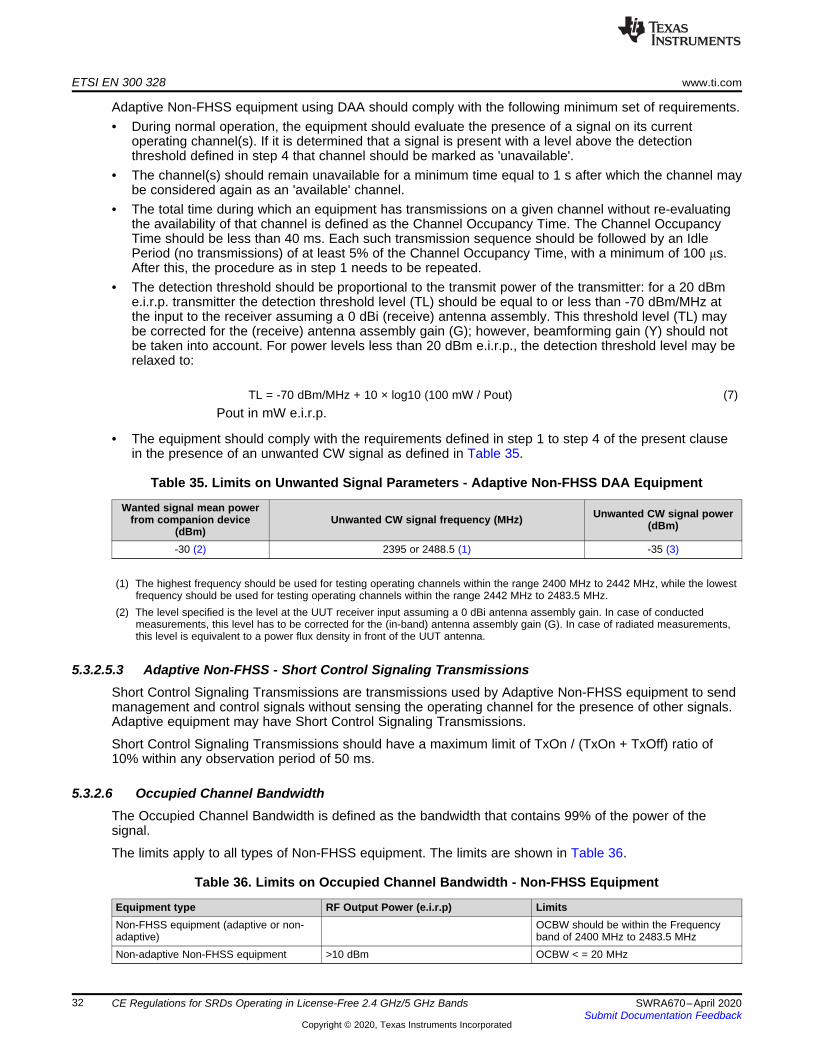
ETSI EN 300 328 www.ti.com
32 SWRA670–April 2020Submit Documentation Feedback
Copyright © 2020, Texas Instruments Incorporated
CE Regulations for SRDs Operating in License-Free 2.4 GHz/5 GHz Bands
Adaptive Non-FHSS equipment using DAA should comply with the following minimum set of requirements.• During normal operation, the equipment should evaluate the presence of a signal on its current
operating channel(s). If it is determined that a signal is present with a level above the detectionthreshold defined in step 4 that channel should be marked as 'unavailable'.
• The channel(s) should remain unavailable for a minimum time equal to 1 s after which the channel maybe considered again as an 'available' channel.
• The total time during which an equipment has transmissions on a given channel without re-evaluatingthe availability of that channel is defined as the Channel Occupancy Time. The Channel OccupancyTime should be less than 40 ms. Each such transmission sequence should be followed by an IdlePeriod (no transmissions) of at least 5% of the Channel Occupancy Time, with a minimum of 100 μs.After this, the procedure as in step 1 needs to be repeated.
• The detection threshold should be proportional to the transmit power of the transmitter: for a 20 dBme.i.r.p. transmitter the detection threshold level (TL) should be equal to or less than -70 dBm/MHz atthe input to the receiver assuming a 0 dBi (receive) antenna assembly. This threshold level (TL) maybe corrected for the (receive) antenna assembly gain (G); however, beamforming gain (Y) should notbe taken into account. For power levels less than 20 dBm e.i.r.p., the detection threshold level may berelaxed to:
TL = -70 dBm/MHz + 10 × log10 (100 mW / Pout) (7)Pout in mW e.i.r.p.
• The equipment should comply with the requirements defined in step 1 to step 4 of the present clausein the presence of an unwanted CW signal as defined in Table 35.
Table 35. Limits on Unwanted Signal Parameters - Adaptive Non-FHSS DAA Equipment
Wanted signal mean powerfrom companion device
(dBm)Unwanted CW signal frequency (MHz) Unwanted CW signal power
(dBm)
-30 (2) 2395 or 2488.5 (1) -35 (3)
(1) The highest frequency should be used for testing operating channels within the range 2400 MHz to 2442 MHz, while the lowestfrequency should be used for testing operating channels within the range 2442 MHz to 2483.5 MHz.
(2) The level specified is the level at the UUT receiver input assuming a 0 dBi antenna assembly gain. In case of conductedmeasurements, this level has to be corrected for the (in-band) antenna assembly gain (G). In case of radiated measurements,this level is equivalent to a power flux density in front of the UUT antenna.
5.3.2.5.3 Adaptive Non-FHSS - Short Control Signaling TransmissionsShort Control Signaling Transmissions are transmissions used by Adaptive Non-FHSS equipment to sendmanagement and control signals without sensing the operating channel for the presence of other signals.Adaptive equipment may have Short Control Signaling Transmissions.
Short Control Signaling Transmissions should have a maximum limit of TxOn / (TxOn + TxOff) ratio of10% within any observation period of 50 ms.
5.3.2.6 Occupied Channel BandwidthThe Occupied Channel Bandwidth is defined as the bandwidth that contains 99% of the power of thesignal.
The limits apply to all types of Non-FHSS equipment. The limits are shown in Table 36.
Table 36. Limits on Occupied Channel Bandwidth - Non-FHSS Equipment
Equipment type RF Output Power (e.i.r.p) LimitsNon-FHSS equipment (adaptive or non-adaptive)
OCBW should be within the Frequencyband of 2400 MHz to 2483.5 MHz
Non-adaptive Non-FHSS equipment >10 dBm OCBW < = 20 MHz

www.ti.com ETSI EN 300 328
33SWRA670–April 2020Submit Documentation Feedback
Copyright © 2020, Texas Instruments Incorporated
CE Regulations for SRDs Operating in License-Free 2.4 GHz/5 GHz Bands
5.3.2.7 Transmitter Unwanted Emissions in the Out-of-Band DomainTransmitter unwanted emissions in the out-of-band domain are defined as emissions on frequenciesimmediately outside the allocated band, but excluding unwanted emissions in the spurious domain, whenthe equipment is in Transmit mode.
The limits apply to all types of Non-FHSS equipment. The limits for unwanted emissions in the out-of-band-domain are shown in Table 37.
Table 37. Limits on Transmitter Unwanted Emissions in Out-of-Band (OOB) domain - Non-FHSS
OOB Band (Frequency Range) (1) Limits (Emission level in e.i.r.p)
From (2400 MHz – BW) to 2400 MHzFrom 2483.5 MHz to (2483.5 MHz + BW)
< -10 dBm/MHz
From (2400 MHz – 2*BW) to (2400 MHz – BW)From (2483.5 MHz + BW) to (2483.5 MHz + 2*BW )
< -20 dBm/MHz
From <(2400 MHz - 2*BW) to 2400 -2*BWFrom >(2483.5 MHz + 2*BW) to (2483.5 MHz + 2*BW)
Refer to spurious domain limits
(1) BW = OCBW in MHz or 1 MHz whichever is greater
5.3.2.8 Transmitter Unwanted Emissions in the Spurious DomainTransmitter unwanted emissions in the spurious domain are defined as emissions outside the allocatedband and outside the out-of-band domain as shown in Table 28, when the equipment is in Transmit mode.
The limits apply to all types of Non-FHSS equipment. The limits for unwanted emissions in the spuriousdomain are shown in Table 38.
In case of equipment with antenna connectors, these limits apply to emissions at the antenna port(conducted). For emissions radiated by the cabinet or emissions radiated by integral antenna equipment(without antenna connectors), these limits are e.r.p. for emissions up to 1 GHz and e.i.r.p. for emissionsabove 1 GHz.
Table 38. Limits on Transmitter Unwanted Emissions in Spurious domain - Non-FHSS
Frequency Range (Spurious Domain) Limits (Maximum power level) Bandwidth30 MHz to 47 MHz -36 dBm 100 kHz47 MHz to 74 MHz -54 dBm 100 kHz74 MHz to 87.5 MHz 36 dBm 100 kHz87.5 MHz to 118 MHz -54 dBm 100 kHz118 MHz to 174 MHz -36 dBm 100 kHz174 MHz to 230 MHz -54 dBm 100 kHz230 MHz to 470 MHz -36 dBm 100 kHz470 MHz to 694 MHz -54 dBm 100 kHz694 MHz to 1 GHz -36 dBm 100 kHz1 GHz to 12.75 GHz -30 dBm 1 MHz
5.3.2.9 Receiver Spurious EmissionsReceiver spurious emissions are defined as emissions at any frequency when the equipment is in receivemode.
The limits apply to all types of Non-FHSS equipment. The limits for receive spurious emissions are shownin Table 39.

ETSI EN 300 328 www.ti.com
34 SWRA670–April 2020Submit Documentation Feedback
Copyright © 2020, Texas Instruments Incorporated
CE Regulations for SRDs Operating in License-Free 2.4 GHz/5 GHz Bands
In case of equipment with antenna connectors, these limits apply to emissions at the antenna port(conducted). For emissions radiated by the cabinet or emissions radiated by integral antenna equipment(without antenna connectors), these limits are e.r.p. for emissions up to 1 GHz and e.i.r.p. for emissionsabove 1 GHz.
Table 39. Limits on Receiver Spurious Emissions - Non-FHSS Equipment
Frequency Range Limits (Maximum power level) Bandwidth30 MHz to 1 GHz -57 dBm 100 kHz1 GHz to 12.75 GHz -47 dBm 1 MHz
5.3.2.10 Receiving BlockingReceiver blocking is defined as a measure of the ability of the equipment to receive a wanted signal on itsoperating channel without exceeding a given degradation due to the presence of an unwanted input signal(blocking signal) on frequencies other than those of the operating band and spurious responses.
If the receiver supports PER/FER tests, then the minimum performance criterion should be a PER or FERof <= 10%. Otherwise, the minimum performance criterion should be no loss of the wireless transmissionfunction needed for the intended use of the equipment.
The requirements apply to all types of Non-FHSS equipment. There are different requirements for differentreceiver categories. The limits for different receiver categories are shown in Table 40.
Table 40. Limits on Receiver Blocking (All Categories) - Non-FHSS Equipment
ReceiverCategory
Wanted signal mean powerfrom companion device
(dBm) (1)(4)
Blockingsignal
frequency(MHz)
Blocking signal power (dBm)(4) Type of blocking signal
1
(-133 dBm + 10 ×log10(OCBW)) or -68 dBm
whichever is less (2)
2380
>=-34 CW
2504
(-139 dBm + 10 ×log10(OCBW)) or -74 dBm
whichever is less (3)
230023302360252425842674
2
(-139 dBm + 10 ×log10(OCBW) + 10 dB) or (-74
dBm + 10 dB) whichever isless (5)
2380
>=-34 CW250423002584
3
(-139 dBm + 10 ×log10(OCBW) + 20 dB) or (-74
dBm + 20 dB) whichever isless (6)
2380
>=-34 CW250423002584
(1) OCBW is in Hz.(2) In case of radiated measurements using a companion device and the level of the wanted signal from the companion device
cannot be determined, a relative test may be performed using a wanted signal up to Pmin + 26 dB where Pmin is the minimumlevel of wanted signal required to meet the minimum performance criteria as defined in this section in the absence of anyblocking signal.
(3) In case of radiated measurements using a companion device and the level of the wanted signal from the companion devicecannot be determined, a relative test may be performed using a wanted signal up to Pmin + 20 dB where Pmin is the minimumlevel of wanted signal required to meet the minimum performance criteria as defined in in this section in the absence of anyblocking signal.
(4) The level specified is the level at the UUT receiver input assuming a 0 dBi antenna assembly gain. In case of conductedmeasurements, this level has to be corrected for the (in-band) antenna assembly gain (G). In case of radiated measurements,

www.ti.com ETSI EN 300 328
35SWRA670–April 2020Submit Documentation Feedback
Copyright © 2020, Texas Instruments Incorporated
CE Regulations for SRDs Operating in License-Free 2.4 GHz/5 GHz Bands
this level is equivalent to a power flux density (PFD) in front of the UUT antenna with the UUT being configured/positioned formaximum e.i.r.p. towards the measuring antenna.
(5) In case of radiated measurements using a companion device and the level of the wanted signal from the companion devicecannot be determined, a relative test may be performed using a wanted signal up to Pmin + 26 dB where Pmin is the minimumlevel of wanted signal required to meet the minimum performance criteria as defined in this section in the absence of anyblocking signal.
(6) In case of radiated measurements using a companion device and the level of the wanted signal from the companion devicecannot be determined, a relative test may be performed using a wanted signal up to Pmin + 30 dB where Pmin is the minimumlevel of wanted signal required to meet the minimum performance criteria as defined in this section in the absence of anyblocking signal.
5.3.2.11 Geo-Location CapabilityGeo-location capability is a feature of the equipment to determine its geographical location with thepurpose to configure itself according to the regulatory requirements applicable at the geographical locationwhere it operates.
The geo-location capability may be present in the equipment or in an external device (temporary)associated with the equipment operating at the same geographical location during the initial power up ofthe equipment. The geographical location may also be available in equipment already installed andoperating at the same geographical location.
The requirement only applies to Non-FHSS equipment with geo-location capability. The geographicallocation determined by the Non-FHSS equipment should not be accessible to the user in a way that wouldallow the user to alter it.
ETSI EN 301 893 www.ti.com
36 SWRA670–April 2020Submit Documentation Feedback
Copyright © 2020, Texas Instruments Incorporated
CE Regulations for SRDs Operating in License-Free 2.4 GHz/5 GHz Bands
6 ETSI EN 301 893The ETSI EN 301 893 is a Harmonized European standard which applies to 5 GHz Wireless AccessSystems (WAS), including RLAN (Radio Local Area Networks) equipment used in wireless local areanetworks for high speed data communication. This standard describes the spectrum access requirements,technical requirements specifications, conformance requirements and test procedures for compliance. Thecomplete document can be downloaded from the ETSI website. The following is the summary of the mostimportant requirements for both the transmitter and the receiver in EN 301 893 standard. The operatingfrequency band limits is shown in Table 41.
Table 41. Limits on Service Frequency Bands - 5 GHz
Mode of operation Frequency BandTransmit 5150 MHz to 5350 MHzReceive 5150 MHz to 5350 MHzTransmit 5470 MHz to 5725 MHzReceive 5470 MHz to 5725 MHz
6.1 Technical RequirementsThe equipment should comply with all applicable technical requirements at all times when operating withinthe boundary limits of the operational environmental profile declared by the manufacturer. The technicalrequirements for different types of equipment are shown in Table 42.
Table 42. Technical Requirements and Conditions
Requirement Requirement Conditionality
No Description
Essentialrequirements of
Directive 2014/53/EUClause(s) of the
EN301 893 U/C (1) Condition1 Carrier frequencies 3.2 4.2.1 U
2Nominal, and
occupied, channelbandwidth
3.2 4.2.2 U
3
RF Output Power 3.2 4.2.3 U Only for non-Adaptive equipment
Transmit PowerControl (TPC) 3.2 4.2.3 C
1) Not required for channels whosenominal bandwidth falls completelywithin the band 5150 MHz to 5250
MHz.2) Not required for devices that
operate at a maximum mean e.i.r.p.of 20 dBm when operating in 5250MHz to 5350 MHz or 27 dBm when
operating in 5470 MHz to 5725MHz.
Power Density 3.2 4.2.3 U
4Transmitter unwantedemissions outside the5 GHz RLAN bands
3.2 4.2.4.1 U
5Transmitter unwantedemissions within the 5
GHz RLAN bands3.2 4.2.4.2 U
6 Receiver spuriousemissions 3.2 4.2.5 U

www.ti.com ETSI EN 301 893
37SWRA670–April 2020Submit Documentation Feedback
Copyright © 2020, Texas Instruments Incorporated
CE Regulations for SRDs Operating in License-Free 2.4 GHz/5 GHz Bands
Table 42. Technical Requirements and Conditions (continued)Requirement Requirement Conditionality
No Description
Essentialrequirements of
Directive 2014/53/EUClause(s) of the
EN301 893 U/C (1) Condition
7 DFS: ChannelAvailability Check 3.2 4.2.6.2.2 C
1) Not required for channels whoseNominal bandwidth falls completelywithin the band 5150 MHz to 5250
MHz.2) Not required for Slave devices
with a maximum transmit power ofless than 200 mW e.i.r.p.
3) Not required at initial use of achannel for slave devices with amaximum transmit power of 200
mW e.i.r.p.
8
DFS: Off-ChannelCAC – Radar
Detection ThresholdLevel
3.2 4.2.6.2.3 C
1) Where implemented by themanufacturer.
2) Not required for channels whosenominal bandwidth falls completelywithin the band 5150 MHz to 5250
MHz.3) Not required for slave devices
with a maximum transmit power ofless than 200 mW e.i.r.p.
4) Not required at initial use of achannel for Slave devices with amaximum transmit power of 200
mW e.i.r.p.
9DFS: Off-ChannelCAC – Detection
Probability3.2 4.2.6.2.3 C
1) Where implemented by themanufacturer.
2) Not required for channels whosenominal bandwidth falls completelywithin the band 5150 MHz to 5250
MHz.3) Not required for slave devices
with a maximum transmit power ofless than 200 mW e.i.r.p.
4) Not required at initial use of achannel for Slave devices with amaximum transmit power of 200
mW e.i.r.p.
10 DFS: In serviceMonitoring 3.2 4.2.6.2.4 C
1) Not required for channels whosenominal bandwidth falls completelywithin the band 5150 MHz to 5250
MHz.2) Not required for Slave devices
with a maximum transmit power ofless than 200 mW e.i.r.p.
11 DFS: Channelshutdown 3.2 4.2.6.2.5 C
Not required for channels whosenominal bandwidth falls completelywithin the band 5150 MHz to 5250
MHz.
12 DFS: Non-occupancyperiod 3.2 4.2.6.2.6 C
1) Not required for channels whosenominal bandwidth falls completelywithin the band 5150 MHz to 5250
MHz.2) Not required for Slave devices
with a maximum transmit power ofless than 200 mW e.i.r.p.
13 DFS: Uniformspreading 3.2 4.2.6.2.7 C
1) Not required for channels whosenominal bandwidth falls completelywithin the band 5150 MHz to 5250
MHz.2) Not required for Slave devices.
14 Adaptivity 3.2 4.2.7 U15 Receiver Blocking 3.2 4.2.8 U

ETSI EN 301 893 www.ti.com
38 SWRA670–April 2020Submit Documentation Feedback
Copyright © 2020, Texas Instruments Incorporated
CE Regulations for SRDs Operating in License-Free 2.4 GHz/5 GHz Bands
Table 42. Technical Requirements and Conditions (continued)Requirement Requirement Conditionality
No Description
Essentialrequirements of
Directive 2014/53/EUClause(s) of the
EN301 893 U/C (1) Condition
16 User AccessRestrictions 3.2 4.2.9 U
17 Geo-locationcapability 3.2 4.2.10 C Where implemented by the
manufacturer.
(1) U/C – Indicates whether the requirement is unconditionally applicable (U) or is conditional upon the manufacturer's claimedfunctionality of the equipment (C).
6.1.1 Environmental ProfileThe environmental profile for operation of the equipment should be declared by the manufacturer. Theequipment should comply with all applicable technical requirements at all times when operating within theboundary limits of the declared operational environmental profile.
6.2 Conformance RequirementsThe Conformance requirements are covered in the following sub-sections.
6.2.1 Nominal Center FrequenciesThe Nominal Center Frequency is defined as the center frequency of the Operating Channel.
The Nominal Center Frequencies (Fc) for a Nominal Channel Bandwidth of 20 MHz are defined by thefollowing equation.
Fc = 5160 + (g × 20) MHz, (8)
where 0 ≤ g ≤ 9 or 16 ≤ g ≤ 27 and where g should be an integer.
A maximum offset of the Nominal Centre Frequency of ±200 kHz is permitted. Where the manufacturerdecides to make use of this frequency offset, the manufacturer should declare the actual centerfrequencies used by the equipment.
The limits on actual center frequency tolerance are shown in Table 43.
Equipment may have simultaneous transmissions on more than one Operating Channel with a NominalChannel Bandwidth of 20 MHz.
Table 43. Limits on Center Frequency
Channel Frequency LimitsActual Center Frequency (Fc) < = Fc ± 20 ppm
6.2.2 Nominal Channel Bandwidth and Occupied Channel BandwidthThe Nominal Channel Bandwidth is defined as the widest band of frequencies, inclusive of guard bands,assigned to a single channel.
The Occupied Channel Bandwidth is defined as the bandwidth containing 99% of the power of the signal.
The limits on Nominal Channel Bandwidth and Occupied Channel Bandwidth are shown in Table 44.

www.ti.com ETSI EN 301 893
39SWRA670–April 2020Submit Documentation Feedback
Copyright © 2020, Texas Instruments Incorporated
CE Regulations for SRDs Operating in License-Free 2.4 GHz/5 GHz Bands
Table 44. Limits on Nominal and Occupied Channel Bandwidth
Parameter Limits
Nominal Channel Bandwidth for a singleoperating channel
20 MHz
or
>5MHz provided if the equipment comply with the Nominal Center Frequencies definedin Section 6.2.1
Occupied Channel Bandwidth for a singleoperating channel
>= 80% <= 100% of Nominal Channel Bandwidth
In case of smart antenna systems (devices with multiple transmit chains) each of thetransmit chains should meet the above requirement.
During a Channel Occupancy Time (COT), equipment may operate temporarily with anoccupied Channel Bandwidth of < 80% of its Nominal Channel Bandwidth with aminimum of 2 MHz
6.2.3 RF Output Power, Transmit Power Control (TPC) and Power DensityThe RF output power is defined as the mean equivalent isotropic radiated power (e.i.r.p.) during atransmission burst.
Transmit Power Control (TPC) is defined as a mechanism to be used by the RLAN device to ensure amitigation factor of at least 3 dB on the aggregate power from a large number of devices. This requires theRLAN device to have a TPC range from which the lowest value is at least 6 dB below the values for meane.i.r.p. given in table 36 for devices with TPC.
The Power Density is defined as the mean equivalent isotropically radiated power (e.i.r.p.) density duringa transmission burst.
The limits below are applicable to the system as a whole and in any possible configuration. This meansthat the antenna gain of the integral or dedicated antenna has to be taken into account as well as theadditional (beamforming) gain in case of smart antenna systems (devices with multiple transmit chains).
In case of multiple (adjacent or non-adjacent) channels within the same sub-band, the total RF OutputPower of all channels in that sub-band should not exceed the limits defined in Table 45 and Table 46.
In case of multiple, non-adjacent channels operating in separate sub-bands, the total RF Output Power ineach of the sub-bands should not exceed the limits defined in Table 45 and Table 46.
TPC is not required for channels whose nominal bandwidth falls completely within the band 5150 MHz to5250 MHz.
The limits on RF output power and the Power Density at the highest power level (PH) of the TPC rangeand without TPC are shown in Table 45.
Table 45. Limits on RF Output Power and Power Density at the Highest Power Level (PH)
FrequencyRange (MHz)
Mean e.i.r.p. limit for PH (dBm) Mean e.i.r.p. density limit (dBm/MHz)With TPC Without TPC With TPC Without TPC
5150 to 5350 < 23 < 20 / 23 (1) < 10 < 7 / 10 (2)5470 to 5725 < 30 (3) < 27 (3) < 17 (3) < 14 (3)
(1) The applicable limit is 20 dBm, except for transmissions whose nominal bandwidth falls completely within the band 5150 MHz to5250 MHz, in which case the applicable limit is 23 dBm.
(2) The applicable limit is 7 dBm/MHz, except for transmissions whose nominal bandwidth falls completely within the band 5150MHz to 5250 MHz, in which case the applicable limit is 10 dBm/MHz.
(3) Slave devices without a Radar Interference Detection function should comply with the limits for the frequency range 5250 MHzto 5350 MHz.
For devices using TPC, the limits on RF output power at the lowest power level (PL) of the TPC range areshown in Table 46.
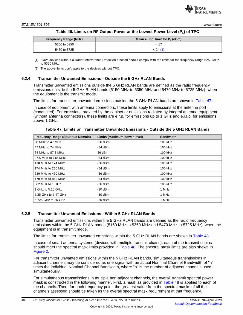
ETSI EN 301 893 www.ti.com
40 SWRA670–April 2020Submit Documentation Feedback
Copyright © 2020, Texas Instruments Incorporated
CE Regulations for SRDs Operating in License-Free 2.4 GHz/5 GHz Bands
Table 46. Limits on RF Output Power at the Lowest Power Level (PL) of TPC
Frequency Range (MHz) Mean e.i.r.p. limit for PL (dBm)5250 to 5350 < 175470 to 5725 < 24 (1)
(1) Slave devices without a Radar Interference Detection function should comply with the limits for the frequency range 5250 MHzto 5350 MHz.
(2) The above limits don’t apply to the devices without TPC.
6.2.4 Transmitter Unwanted Emissions - Outside the 5 GHz RLAN BandsTransmitter unwanted emissions outside the 5 GHz RLAN bands are defined as the radio frequencyemissions outside the 5 GHz RLAN bands (5150 MHz to 5350 MHz and 5470 MHz to 5725 MHz), whenthe equipment is the transmit mode.
The limits for transmitter unwanted emissions outside the 5 GHz RLAN bands are shown in Table 47.
In case of equipment with antenna connectors, these limits apply to emissions at the antenna port(conducted). For emissions radiated by the cabinet or emissions radiated by integral antenna equipment(without antenna connectors), these limits are e.r.p. for emissions up to 1 GHz and e.i.r.p. for emissionsabove 1 GHz.
Table 47. Limits on Transmitter Unwanted Emissions - Outside the 5 GHz RLAN Bands
Frequency Range (Spurious Domain) Limits (Maximum power level) Bandwidth30 MHz to 47 MHz -36 dBm 100 kHz47 MHz to 74 MHz -54 dBm 100 kHz74 MHz to 87.5 MHz 36 dBm 100 kHz87.5 MHz to 118 MHz -54 dBm 100 kHz118 MHz to 174 MHz -36 dBm 100 kHz174 MHz to 230 MHz -54 dBm 100 kHz230 MHz to 470 MHz -36 dBm 100 kHz470 MHz to 862 MHz -54 dBm 100 kHz862 MHz to 1 GHz -36 dBm 100 kHz1 GHz to 5.15 GHz -30 dBm 1 MHz5.35 GHz to 5.47 GHz -30 dBm 1 MHz5.725 GHz to 26 GHz -30 dBm 1 MHz
6.2.5 Transmitter Unwanted Emissions - Within 5 GHz RLAN BandsTransmitter unwanted emissions within the 5 GHz RLAN bands are defined as the radio frequencyemissions within the 5 GHz RLAN bands (5150 MHz to 5350 MHz and 5470 MHz to 5725 MHz), when theequipment is in transmit mode.
The limits for transmitter unwanted emissions within the 5 GHz RLAN bands are shown in Table 48.
In case of smart antenna systems (devices with multiple transmit chains), each of the transmit chainsshould meet the spectral mask limits provided in Table 48. The spectral mask limits are also shown inFigure 2.
For transmitter unwanted emissions within the 5 GHz RLAN bands, simultaneous transmissions inadjacent channels may be considered as one signal with an actual Nominal Channel Bandwidth of "n"times the individual Nominal Channel Bandwidth, where "n" is the number of adjacent channels usedsimultaneously.
For simultaneous transmissions in multiple non-adjacent channels, the overall transmit spectral powermask is constructed in the following manner. First, a mask as provided in Table 48 is applied to each ofthe channels. Then, for each frequency point, the greatest value from the spectral masks of all thechannels assessed should be taken as the overall spectral mask requirement at that frequency.

Relative Level (dB
-0,5 x N-0,55 x N
-1,5 x N -N-9 x N-10,8 x N
0,55 x N
9 x N1,5 x N
0,5 x N
10,8 x N
Frequency Offset (MHz)
-47 dB
-42 dB-40 dB
-28 dB
-20 dB
0 dB = Reference Level
N = Normal Channel Bandwidth
www.ti.com ETSI EN 301 893
41SWRA670–April 2020Submit Documentation Feedback
Copyright © 2020, Texas Instruments Incorporated
CE Regulations for SRDs Operating in License-Free 2.4 GHz/5 GHz Bands
In case of equipment with antenna connectors, these limits apply to emissions at the antenna port(conducted). For emissions radiated by the cabinet or emissions radiated by integral antenna equipment(without antenna connectors), these limits are e.r.p. for emissions up to 1 GHz and e.i.r.p. for emissionsabove 1 GHz.
Table 48. Limits on Transmitter Unwanted Emissions - Within the 5 GHz RLAN Bands
Frequency relative to the Center of theChannel
LimitsRelative spurlevel to the
Maximum PowerDensity in 1MHz
Bandwidth,dBc/MHz
Absolute Spur levelof the Power Densityin 1MHz Bandwidth,
dBm/MHzRequirement
From < ((-10.8)*N) to (-10.8)*N <= -47 <= -30
should not exceed either Relative levelor an Absolute level, whichever isgreater.
From ((-10.8)*N ) to (-9*N) <= -42 <= -30From (-9*N ) to (-1.5*N) <= -40 <= -30
At -1*N <= -28 <= -30At -0.55*N <= -20 <= -30At -0.50*N 0
From (-0.5*N) to (0*N) 0
At 0*N 0 (ReferenceLevel)
From (0*N) to (0.5*N) 0At +0.50*N 0At +0.55*N <= -20 <= -30
At +1*N <= -28 <= -30From (1.5*N ) to (9*N) <= -40 <= -30
From (9*N ) to ((10.8)*N) <= -42 <= -30From > ( (10.8)* N ) to (10.8)* N <= -47 <= -30
N = Nominal Channel Bandwidth in MHz
Figure 2. Transmit Spectral Power Mask

ETSI EN 301 893 www.ti.com
42 SWRA670–April 2020Submit Documentation Feedback
Copyright © 2020, Texas Instruments Incorporated
CE Regulations for SRDs Operating in License-Free 2.4 GHz/5 GHz Bands
6.2.6 Receiver Spurious EmissionsReceiver spurious emissions are defined as emissions at any frequency when the equipment is in receivemode.
The limits for receiver spurious emissions are shown in Table 49.
In case of equipment with antenna connectors, these limits apply to emissions at the antenna port(conducted). For emissions radiated by the cabinet or emissions radiated by integral antenna equipment(without antenna connectors), these limits are e.r.p. for emissions up to 1 GHz and e.i.r.p. for emissionsabove 1 GHz.
Table 49. Limits on Receiver Spurious Emissions
Frequency Range Limits (Maximum power level) Bandwidth30 MHz to 1 GHz -57 dBm 100 kHz1 GHz to 12.75 GHz -47 dBm 1 MHz
6.2.7 Dynamic Frequency Selection (DFS)An RLAN should employ a Dynamic Frequency Selection (DFS) function to:• Detect interference from radar systems (radar detection) and to avoid co-channel operation with these
systems;• Provide on aggregate a near-uniform loading of the spectrum (Uniform Spreading).
Within the context of the operation of the DFS function, an RLAN device should operate as either a masteror a slave. RLAN devices operating as a slave should only operate in a network controlled by an RLANdevice operating as a master. A device which is capable of operating as either a master or a slave shouldcomply with the requirements applicable to the mode in which it operates.
Some RLAN devices are capable of communicating in ad-hoc manner without being attached to anetwork. RLAN devices operating in ad-hoc manner on channels whose nominal bandwidth falls partly orcompletely within the frequency ranges 5250 MHz to 5350 MHz or 5470 MHz to 5725 MHz should employDFS and should be tested against the requirements applicable to a master.
Slave devices used in fixed outdoor point to point or fixed outdoor point to multipoint applications shouldbehave as slave with radar detection independent of their output power.
Refer to ETSI EN 301 893 for a detailed operational behavior and individual requirements for both masterand slave devices.
The DFS requirements and their applicability are shown in Table 50.
In case of equipment with antenna connectors, these limits apply to emissions at the antenna port(conducted). For emissions radiated by the cabinet or emissions radiated by integral antenna equipment(without antenna connectors), these limits are e.r.p. for emissions up to 1 GHz and e.i.r.p. for emissionsabove 1 GHz.
Table 50. DFS Requirements and their Applicability
RequirementDFS Operational mode
Master Slave without radar detection(see Table 52, (2))
Slave with radar detection (seeTable 52, (2))
RadarInterference
detectionFunction
Required (3) Not required Required
ChannelAvailability
CheckRequired Not required Required (2)
Off-ChannelCAC (see (1)) Required Not required Required (2)

www.ti.com ETSI EN 301 893
43SWRA670–April 2020Submit Documentation Feedback
Copyright © 2020, Texas Instruments Incorporated
CE Regulations for SRDs Operating in License-Free 2.4 GHz/5 GHz Bands
Table 50. DFS Requirements and their Applicability (continued)
RequirementDFS Operational mode
Master Slave without radar detection(see Table 52, (2))
Slave with radar detection (seeTable 52, (2))
In-ServiceMonitoring Required Not required Required
ChannelShutdown Required Required Required
Non-OccupancyPeriod Required Not required Required
UniformSpreading Required (4) Not required Not required
(1) Where implemented by the manufacturer.(2) A slave with radar detection is not required to perform a CAC or Off-Channel CAC at initial use of the channel but only after the
slave has detected a radar signal on the Operating Channel by In-Service Monitoring and the Non-Occupancy Period resultingfrom this detection has elapsed.
(3) Radar detection should be used when operating on channels whose nominal bandwidth falls partly or completely within thefrequency ranges 5250 MHz to 5350 MHz or 5470 MHz to 5725 MHz.
(4) Uniform Spreading is required across the frequency ranges 5150 MHz to 5350 MHz and 5470 MHz to 5725 MHz. UniformSpreading is not applicable for equipment that only operates in the band 5150 MHz to 5250 MHz.
The limits for the DFS requirements are shown in Table 51.
Table 51. Limits on DFS Requirements
Parameter LimitsChannel Availability Check Time > 60 Seconds (1)Minimum Off-Channel CAC Time > 6 Minutes (2)Maximum Off-Channel CAC Time < 4 Hours (2)
Channel Move Time < 10 SecondsChannel Closing Transmission Time < 1 Second
Non-Occupancy Period > 30 Minutes
(1) For channels whose nominal bandwidth falls completely or partly within the band 5600 MHz to 5650 MHz, the ChannelAvailability Check Time should be 10 minutes.
(2) For channels whose nominal bandwidth falls completely or partly within the band 5600 MHz to 5650 MHz, the Off-Channel CACTime should be within the range 1 hour to 24 hours.
The limits for the Radar Detection Threshold levels are shown in Table 52.
Table 52. Limits on Radar Detection Threshold Levels
e.i.r.p. Spectral Density (dBm/MHz) Limits (1)(2)10 -62 dBm
(1) This is the level at the input of the receiver of an RLAN device with a maximum e.i.r.p. density of 10 dBm/MHz and assuming a0 dBi receive antenna. For devices employing different e.i.r.p. spectral density and/or a different receive antenna gain G (dBi)the Radar Detection Threshold Level at the receiver input follows the following relationship:DFS Detection Threshold (dBm) = -62 + 10 - e.i.r.p. Spectral Density (dBm/MHz) + G (dBi);however the Radar Detection Threshold Level should not be less than -64 dBm assuming a 0 dBi receive antenna gain.
(2) Slave devices with a maximum e.i.r.p. of less than 23 dBm do not have to implement radar detection unless these devices areused in fixed outdoor point to point or fixed outdoor point to multipoint applications.
The parameters of the reference DFS test signal are shown in Table 53.
Table 53. Parameters of the Reference DFS Test Signal
Pulse width W (μs) Pulse repetition frequency PRF (PPS) Pulses per burst (PPB)1 700 18
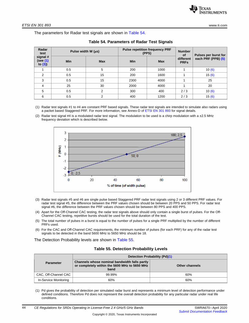
ETSI EN 301 893 www.ti.com
44 SWRA670–April 2020Submit Documentation Feedback
Copyright © 2020, Texas Instruments Incorporated
CE Regulations for SRDs Operating in License-Free 2.4 GHz/5 GHz Bands
The parameters for Radar test signals are shown in Table 54.
Table 54. Parameters of Radar Test Signals
Radartest
signal #(see (1)to (3))
Pulse width W (μs) Pulse repetition frequency PRF(PPS) Number
ofdifferent
PRFs
Pulses per burst foreach PRF (PPB) (5)
Min Max Min Max
1 0.5 5 200 1000 1 10 (6)2 0.5 15 200 1600 1 15 (6)3 0.5 15 2300 4000 1 254 25 30 2000 4000 1 205 0.5 2 300 400 2 / 3 10 (6)6 0.5 2 400 1200 2 / 3 15 (6)
(1) Radar test signals #1 to #4 are constant PRF based signals. These radar test signals are intended to simulate also radars usinga packet based Staggered PRF. For more information, see Annex-D of ETSI EN 301 893 for signal details.
(2) Radar test signal #4 is a modulated radar test signal. The modulation to be used is a chirp modulation with a ±2.5 MHzfrequency deviation which is described below.
(3) Radar test signals #5 and #6 are single pulse based Staggered PRF radar test signals using 2 or 3 different PRF values. Forradar test signal #5, the difference between the PRF values chosen should be between 20 PPS and 50 PPS. For radar testsignal #6, the difference between the PRF values chosen should be between 80 PPS and 400 PPS.
(4) Apart for the Off-Channel CAC testing, the radar test signals above should only contain a single burst of pulses. For the Off-Channel CAC testing, repetitive bursts should be used for the total duration of the test.
(5) The total number of pulses in a burst is equal to the number of pulses for a single PRF multiplied by the number of differentPRFs used.
(6) For the CAC and Off-Channel CAC requirements, the minimum number of pulses (for each PRF) for any of the radar testsignals to be detected in the band 5600 MHz to 5650 MHz should be 18.
The Detection Probability levels are shown in Table 55.
Table 55. Detection Probability Levels
Parameter
Detection Probability (Pd)(1)Channels whose nominal bandwidth falls partlyor completely within the 5600 MHz to 5650 MHz
bandOther channels
CAC, Off-Channel CAC 99.99% 60%In-Service Monitoring 60% 60%
(1) Pd gives the probability of detection per simulated radar burst and represents a minimum level of detection performance underdefined conditions. Therefore Pd does not represent the overall detection probability for any particular radar under real lifeconditions.
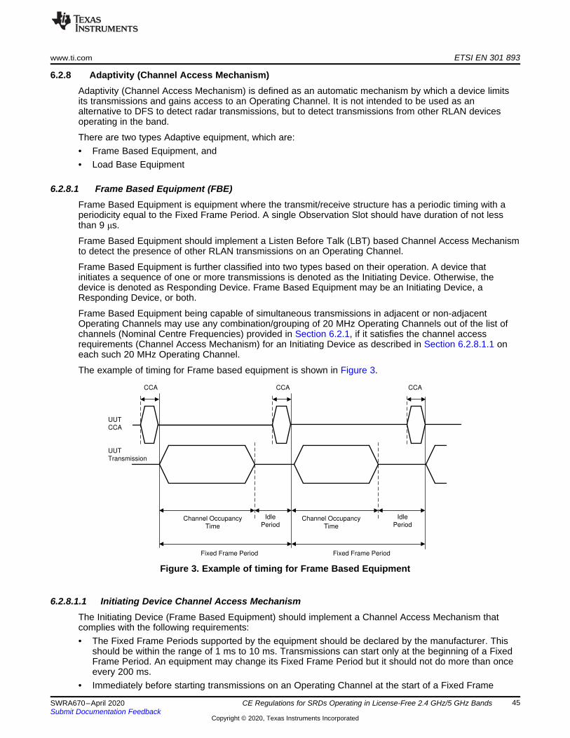
UUT
CCA
UUT
Transmission
Idle
PeriodChannel Occupancy
Time
Idle
PeriodChannel Occupancy
Time
Fixed Frame Period Fixed Frame Period
CCA CCA CCA
www.ti.com ETSI EN 301 893
45SWRA670–April 2020Submit Documentation Feedback
Copyright © 2020, Texas Instruments Incorporated
CE Regulations for SRDs Operating in License-Free 2.4 GHz/5 GHz Bands
6.2.8 Adaptivity (Channel Access Mechanism)Adaptivity (Channel Access Mechanism) is defined as an automatic mechanism by which a device limitsits transmissions and gains access to an Operating Channel. It is not intended to be used as analternative to DFS to detect radar transmissions, but to detect transmissions from other RLAN devicesoperating in the band.
There are two types Adaptive equipment, which are:• Frame Based Equipment, and• Load Base Equipment
6.2.8.1 Frame Based Equipment (FBE)Frame Based Equipment is equipment where the transmit/receive structure has a periodic timing with aperiodicity equal to the Fixed Frame Period. A single Observation Slot should have duration of not lessthan 9 μs.
Frame Based Equipment should implement a Listen Before Talk (LBT) based Channel Access Mechanismto detect the presence of other RLAN transmissions on an Operating Channel.
Frame Based Equipment is further classified into two types based on their operation. A device thatinitiates a sequence of one or more transmissions is denoted as the Initiating Device. Otherwise, thedevice is denoted as Responding Device. Frame Based Equipment may be an Initiating Device, aResponding Device, or both.
Frame Based Equipment being capable of simultaneous transmissions in adjacent or non-adjacentOperating Channels may use any combination/grouping of 20 MHz Operating Channels out of the list ofchannels (Nominal Centre Frequencies) provided in Section 6.2.1, if it satisfies the channel accessrequirements (Channel Access Mechanism) for an Initiating Device as described in Section 6.2.8.1.1 oneach such 20 MHz Operating Channel.
The example of timing for Frame based equipment is shown in Figure 3.
Figure 3. Example of timing for Frame Based Equipment
6.2.8.1.1 Initiating Device Channel Access MechanismThe Initiating Device (Frame Based Equipment) should implement a Channel Access Mechanism thatcomplies with the following requirements:• The Fixed Frame Periods supported by the equipment should be declared by the manufacturer. This
should be within the range of 1 ms to 10 ms. Transmissions can start only at the beginning of a FixedFrame Period. An equipment may change its Fixed Frame Period but it should not do more than onceevery 200 ms.
• Immediately before starting transmissions on an Operating Channel at the start of a Fixed Frame

ETSI EN 301 893 www.ti.com
46 SWRA670–April 2020Submit Documentation Feedback
Copyright © 2020, Texas Instruments Incorporated
CE Regulations for SRDs Operating in License-Free 2.4 GHz/5 GHz Bands
Period, the Initiating Device should perform a Clear Channel Assessment (CCA) check during a singleObservation Slot. The Operating Channel should be considered occupied if the energy level in thechannel exceeds the ED Threshold Level (TL) given in point 6) below. If the Initiating Device finds theOperating Channel(s) to be clear, it may transmit immediately. See Figure 1.If the Initiating Device finds an Operating Channel occupied, then there should be no transmissions onthat channel during the next Fixed Frame Period. The Frame Based Equipment is allowed to continueShort Control Signalling Transmissions on this channel providing it complies with the requirementsgiven in Section 6.2.8.3.For equipment having simultaneous transmissions on multiple (adjacent or non-adjacent) OperatingChannels, the equipment is allowed to continue transmissions on other Operating Channels providingthe CCA check did not detect any signals on those channels.The total time during which Frame Based Equipment can have transmissions on a given channelwithout re-evaluating the availability of that channel, is defined as the Channel Occupancy Time (COT).The equipment can have multiple transmissions within a Channel Occupancy Time without performingan additional CCA on this Operating Channel providing the gap between such transmissions does notexceed 16 μs.If the gap exceeds 16 μs, the equipment may continue transmissions provided that an additional CCAdetects no RLAN transmissions with a level above the threshold defined in point 6. The additional CCAshould be performed within the gap and within the observation slot immediately before transmission.All gaps are counted as part of the Channel Occupancy Time.
• An Initiating Device is allowed to grant an authorization to one or more associated RespondingDevices to transmit on the current Operating Channel within the current Channel Occupancy Time. AResponding Device that receives such a grant should follow the procedure described inSection 6.2.8.1.2.
• The Channel Occupancy Time should not be greater than 95% of the Fixed Frame Period defined inpoint 1 and should be followed by an Idle Period until the start of the next Fixed Frame Period suchthat the Idle Period is at least 5% of the Channel Occupancy Time, with a minimum of 100 μs.
• The equipment, upon correct reception of a packet which was intended for this equipment, can skipCCA and immediately proceed with the transmission of management and control frames (for example,ACK and Block ACK frames). A consecutive sequence of such transmissions by the equipment,without it performing a new CCA, should not exceed the Maximum Channel Occupancy Time asdefined in point 4 above.For the purpose of multi-cast, the ACK transmissions (associated with the same data packet) of theindividual devices are allowed to take place in a sequence.
• The ED Threshold Level (TL), at the input of the receiver, should be proportional to the maximumtransmit power (PH) according to the formula which assumes a 0 dBi receive antenna and PH to bespecified in dBm e.i.r.p. The levels are shown in Table 56.
Table 56. Limits on ED Threshol Level - FBE
Maximum Tx Power (e.i.r.p.), dBm(PH) ED Threshold Level (TL) (1) Notes
For PH ≤ 13 dBm -75 dBm/MHzAssumes a 0 dBi receive antenna
gainFor 13 dBm < PH < 23 dBm -85 dBm/MHz + (23 dBm - PH)For PH ≥ 23 dBm -85 dBm/MHz
(1) Equipment should consider a channel to be occupied as long as other RLAN transmissions are detected at a level greater thanthe TL.
6.2.8.1.2 Responding Device Channel Access MechanismA Responding Device that receives a grant from a Initiating Device to transmit on the current OperatingChannel within the current Fixed Frame Period should follow the procedure described in following steps 1to 3:1. A Responding Device that received a transmission grant from an associated Initiating Device may
proceed with transmissions on the current Operating Channel:a. The Responding Device may proceed with such transmissions without performing a Clear Channel
Assessment (CCA) if these transmissions are initiated at most 16 μs after the last transmission by

www.ti.com ETSI EN 301 893
47SWRA670–April 2020Submit Documentation Feedback
Copyright © 2020, Texas Instruments Incorporated
CE Regulations for SRDs Operating in License-Free 2.4 GHz/5 GHz Bands
the Initiating Device that issued the grant.b. The Responding Device that does not proceed with such transmissions within 16 μs after the last
transmission from the Initiating Device that issued the grant, should perform a Clear ChannelAssessment (CCA) on the Operating Channel during a single observation slot within a 25 μs periodending immediately before the granted transmission time. If energy was detected with a levelabove the ED Threshold Level (TL) defined in Table 47, the Responding Device should proceedwith step 3. Otherwise, the Responding Device should proceed with step 2.
2. The Responding Device may perform transmissions on the current Operating Channel for theremaining Channel Occupancy Time of the current Fixed Frame Period. The Responding Device mayhave multiple transmissions on this Operating Channel provided that the gap in between suchtransmissions does not exceed 16 μs. When the transmissions by the Responding Device arecompleted the Responding Device should proceed with step 3.
3. The transmission grant for the Responding Device is withdrawn.
6.2.8.2 Load Based Equipment (LBE)Load based Equipment should implement a Listen Before Talk (LBT) based Channel Access Mechanismto detect the presence of other RLAN transmissions on an Operating Channel.
6.2.8.2.1 Device Types - Load Based EquipmentLoad based Equipment is further classified into different types of devices based on their operation withregard to Adaptivity. A device that initiates a sequence of one or more transmissions is denoted as theInitiating Device. Otherwise, the device is denoted as Responding Device. Load Based Equipment may bean Initiating Device, a Responding Device, or both. Each transmission belongs to a single ChannelOccupancy Time (COT). A Channel Occupancy Time (COT) consists of one or more transmissions of anInitiating Device and zero or more transmissions of one or more Responding Devices.
An equipment that controls (non-DFS related) operating parameters of one or more other equipment isdenoted as a Supervising Device. Otherwise, the equipment is denoted as a Supervised Device. The rolesof a Supervising Device and Supervised Device has only to be seen in relation to Adaptivity and aredifferent from the roles of a Master device and a Slave Device in the context of DFS as defined inSection 6.2.7. Examples of Supervising Devices are an RLAN Access Point or a mobile phone operatingas an RLAN hotspot.
6.2.8.2.2 Multi-Channel Operation - Load Based EquipmentLoad Based Equipment being capable of simultaneous transmissions in adjacent or non-adjacentOperating Channels (see Section 6.2.1) should implement either option 1 or option 2 below:
Option 1: Load Based Equipment may use any combination/grouping of 20 MHz Operating Channels outof the list of channels (Nominal Centre Frequencies) provided in Section 6.2.1, if it satisfies the channelaccess requirements (Channel Access Mechanism) for an Initiating Device as described inSection 6.2.8.2.5 on each such 20 MHz Operating Channel.
Option 2: The bonded 40 MHz, 80 MHz or 160 MHz channels (see also clause 4.2.1.3 for the channelnumber) are defined and shown in Figure 4. Load Based Equipment that uses a combination/grouping of20 MHz Operating Channels that is a subset of bonded 40 MHz, 80 MHz or 160 MHz channels, maytransmit on any of the 20 MHz Operating Channels, if:• The equipment satisfies the channel access requirements (Channel Access Mechanism) for an
Initiating Device as defined in Section 6.2.8.2.5 on one of the 20 MHz Operating Channels (PrimaryOperating Channel), and
• The equipment performs a Clear Channel Assessment (CCA) of at least 25 μs immediately before theintended transmissions on each of the other Operating Channels on which transmissions are intended,and no energy was detected with a level above the ED Threshold Level (TL) defined inSection 6.2.8.2.4.
The choice of the Primary Operating Channel should follow one of the following procedures:• The Primary Operating Channel is chosen uniformly randomly whenever the contention window (CW),
corresponding to a completed transmission on the current Primary Operating Channel is set to its

0 1 2 3 4 5 6 7 8 9 16 17 18 19 20 21 22 23 24 25 26 2720 MHz channels
40 MHz channels
80 MHz channels
160 MHz channels
5 1
50
MH
z
5 1
70
MH
z
5 2
50
MH
z
5 3
30
MH
z
5 3
50
MH
z
5 4
70
MH
z
5 4
90
MH
z
5 6
90
MH
z
5 7
10
MH
z
5 7
25
MH
z
ETSI EN 301 893 www.ti.com
48 SWRA670–April 2020Submit Documentation Feedback
Copyright © 2020, Texas Instruments Incorporated
CE Regulations for SRDs Operating in License-Free 2.4 GHz/5 GHz Bands
minimum value (CWmin). For this procedure, a contention window (CW) is maintained for each PriorityClass (see Section 6.2.8.2.3). within each 20 MHz Operating Channel within the bonded channel.
• The Primary Operating Channel is arbitrarily determined and not changed more than once per second.
The bonded 40 MHz, 80 MHz or 160 MHz channel that the combination/grouping of 20 MHz operatingchannels is a subset of should not be changed more than once per second.
Figure 4. Channel Bonding for option 2
6.2.8.2.3 Priority Classes - Load Based EquipmentThere are four different sets of Channel Access parameters for Supervising Devices and SupervisedDevices respectively, resulting in different Priority Classes and different maximum Channel OccupancyTimes. These parameters are used by the Channel Access Mechanism for the Initiating Device describedin section 6.2.8.2.5Section 6.2.8.2.5 to gain access to an Operating Channel. The parameters forSupervising Devices are shown in Table 57 and the parameters for Supervised devices are shown inTable 58.
If a Channel Occupancy consists of more than one transmission the transmissions may be separated bygaps. The Channel Occupancy Time is the total duration of all transmissions and all gaps of 25 μsduration or less within a Channel Occupancy and should not exceed the maximum Channel OccupancyTime in Table 57 and Table 58. The duration from the start of the first transmission within a ChannelOccupancy until the end of the last transmission in that same Channel Occupancy should not exceed 20ms.
The Initiating Device may have data to be transmitted in different Priority Classes and therefore theChannel Access Mechanism is allowed to operate different Channel Access Engines as described inSection 6.2.8.2.4 simultaneously (one for each implemented Priority Class).
Table 57. Priority Class Dependent Channel Access Parameters for Supervising Devices
Class # p0(3) CWmin(3) CWmax(3)Maximum Channel
Occupancy Time (COT),mSec
4 1 3 7 23 1 7 15 42 3 15 63 6 (1)(2)1 7 15 1023 6 (1)

www.ti.com ETSI EN 301 893
49SWRA670–April 2020Submit Documentation Feedback
Copyright © 2020, Texas Instruments Incorporated
CE Regulations for SRDs Operating in License-Free 2.4 GHz/5 GHz Bands
(1) The maximum Channel Occupancy Time (COT) of 6 ms may be increased to 8 ms by inserting one or more pauses. Theminimum duration of a pause should be 100 μs. The maximum duration (Channel Occupancy) before including any such pauseshould be 6 ms. Pause duration is not included in the channel occupancy time.
(2) The maximum Channel Occupancy Time (COT) of 6 ms may be increased to 10 ms by extending CW to CW × 2 + 1 whenselecting the random number q for any backoff(s) that precede the Channel Occupancy that may exceed 6 ms or which followthe Channel Occupancy that exceeded 6 ms. The choice between preceding or following a Channel Occupancy should remainunchanged during the operation time of the device.
(3) The values for p0, CWmin, CWmax are minimum values. Greater values are allowed.
Table 58. Priority Class Dependent Channel Access Parameters for Supervised Devices
Class # p0(2) CWmin(2) CWmax(2)Maximum Channel
Occupancy Time (COT),mSec
4 2 3 7 23 2 7 15 42 3 15 1023 6 (1)1 7 15 1023 6 (1)
(1) The maximum Channel Occupancy Time (COT) of 6 ms may be increased to 8 ms by inserting one or more pauses. Theminimum duration of a pause should be 100 μs. The maximum duration (Channel Occupancy) before including any such pauseshould be 6 ms. Pause duration is not included in the channel occupancy time.
(2) The values for p0, CWmin, CWmax are minimum values. Greater values are allowed.
6.2.8.2.4 ED Threshold Level - Load Based EquipmentEquipment should consider a channel to be occupied as long as other RLAN transmissions are detectedat a level greater than the ED Threshold Level (TL). The ED Threshold Level (TL) is integrated over thetotal Nominal Channel Bandwidth of all Operating Channels used by the equipment. The ED Thresholdlevel (TL) depends on the type of equipment:
Option 1: For equipment that for its operation in the 5 GHz bands is conforming to IEEE 802.11™-2016,clause 17, clause 19 or clause 21, or any combination of these clauses, the ED Threshold Level (TL) isindependent of the equipment's maximum transmit power (PH). Assuming a 0 dBi receive antenna the EDThreshold Level (TL) should be:
TL = -75 dBm/MHz (9)
Option 2: For equipment conforming to one or more of the clauses listed in Option 1, and to at least oneother operating mode, and for equipment conforming to none of the clauses listed in Option 1, the EDThreshold Level (TL) should be proportional to the maximum transmit power (PH) according to the formulawhich assumes a 0 dBi receive antenna and PH to be specified in dBm e.i.r.p. The levels are shown inTable 59.
Table 59. Limits on ED Threshold Level - LBE
Maximum Tx Power (e.i.r.p.),dBm (PH) ED Threshold Level (TL)(1) Notes
For PH ≤ 13 dBm -75 dBm/MHzAssumes a 0 dBi receive antenna gain.For 13 dBm < PH < 23 dBm -85 dBm/MHz + (23 dBm - PH)
For PH ≥ 23 dBm -85 dBm/MHz
(1) Equipment should consider a channel to be occupied as long as other RLAN transmissions are detected at a level greater thanthe TL.

ETSI EN 301 893 www.ti.com
50 SWRA670–April 2020Submit Documentation Feedback
Copyright © 2020, Texas Instruments Incorporated
CE Regulations for SRDs Operating in License-Free 2.4 GHz/5 GHz Bands
6.2.8.2.5 Initiating Device Channel Access Mechanism - Load Based EquipmentBefore a transmission or a burst of transmissions on an Operating Channel, the Initiating Device shouldoperate at least one Channel Access Engine that executes the procedure described in the following steps1 to step 8. This Channel Access Engine makes use of the parameters defined in Table 57 or Table 58 inSection 6.2.8.2.3.
A single Observation Slot should have a duration of not less than 9 μs.
An Initiating Device should operate at least one and no more than four different Channel Access Engineseach with a different Priority Class as defined in Section 6.2.8.2.3:1. The Channel Access Engine should set CW to CWmin.2. The Channel Access Engine should select a random number q from a uniform distribution over the
range 0 to CW. (3) in Table 57 defines an alternative range for q when the previous or next ChannelOccupancy Time is greater than the maximum Channel Occupancy Time specified in Table 57.
3. The Channel Access Engine should initiate a Prioritization Period as described in the following steps a)to c):a. The Channel Access Engine should set p according to the Priority Class associated with this
Channel Access Engine. See Section 6.2.8.2.3.b. The Channel Access Engine should wait for a period of 16 μs.c. The Channel Access Engine should perform a Clear Channel Assessment (CCA) on the Operating
Channel during a single Observation Slot:i. The Operating Channel should be considered occupied if other transmissions within this
channel are detected with a level above the ED threshold defined in Section 6.2.8.2.4. In thiscase, the Channel Access Engine should initiate a new Prioritization Period starting with step3a) after the energy within the channel has dropped below the ED threshold defined inSection 6.2.8.2.4.
ii. In case no energy within the Operating Channel is detected with a level above the EDthreshold defined in Section 6.2.8.2.4, p may be decremented by not more than 1. If p is equalto 0, the Channel Access Engine should proceed with step 4, otherwise the Channel AccessEngine should proceed with step 3c).
4. The Channel Access Engine should perform a Backoff Procedure as described in step 4a) to step 4d):a. This step verifies if the Channel Access Engine satisfies the Post Backoff condition. If q < 0 and
the Channel Access Engine is ready for a transmission, the Channel Access Engine should setCW equal to CWmin and should select a random number q from a uniform distribution over therange 0 to CW before proceeding with step 4b). (3) in Table 57 defines an alternative range forwhen the previous or next Channel Occupancy Time is greater than the maximum ChannelOccupancy Time specified in Table 57.
b. If q < 1 the Channel Access Engine should proceed with step 4d). Otherwise, the Channel AccessEngine may decrement the value q by not more than 1 and the Channel Access Engine shouldproceed with step 4c).
c. The Channel Access Engine should perform a Clear Channel Assessment (CCA) on the OperatingChannel during a single Observation Slot:i. The Operating Channel should be considered occupied if energy was detected with a level
above the ED threshold defined in Section 6.2.8.2.4. In this case, the Channel Access Engineshould continue with step 3.
ii. If no energy was detected with a level above the ED threshold defined in Section 6.2.8.2.4, theChannel Access Engine should continue with step 4 b).
d. If the Channel Access Engine is ready for a transmission the Channel Access Engine shouldcontinue with step 5. Otherwise, the Channel Access Engine should decrement the value q by 1and the Channel Access Engine should proceed with step 4c). It should be understood that q canbecome negative and keep decrementing as long as the Channel Access Engine is not ready for atransmission.
5. If only one Channel Access Engine of the Initiating Device is in this stage, the Channel Access Engineshould proceed with step 6. If the Initiating Device has a multitude of Channel Access Engines in thisstage, the Channel Access Engine with highest Priority Class in this multitude should proceed with

www.ti.com ETSI EN 301 893
51SWRA670–April 2020Submit Documentation Feedback
Copyright © 2020, Texas Instruments Incorporated
CE Regulations for SRDs Operating in License-Free 2.4 GHz/5 GHz Bands
step 6 and all other Channel Access Engines in the current stage should proceed with step 8.a. One Channel Access Engine of the Initiating Device is in this stage: This is equivalent to the
equipment having no internal collisionb. Initiating Device has a multitude of Channel Access Engines in this stage: This is equivalent to the
equipment having one or more internal collisions6. The Channel Access Engine may start transmissions belonging to the corresponding or higher Priority
Classes, on one or more Operating Channels. If the initiating device transmits in more than oneOperating Channels, it should comply with the requirements contained in Section 6.2.8.2.2:a. The Channel Access Engine can have multiple transmissions without performing an additional
CCA on this Operating Channel providing the gap in between such transmissions does not exceed16 μs. Otherwise, if this gap exceeds 16 μs and does not exceed 25 μs, the Initiating Device maycontinue transmissions provided that no energy was detected with a level above the ED thresholddefined in Section 6.2.8.2.4 for a duration of one Observation Slot.
b. The Channel Access Engine may grant an authorization to transmit on the current OperatingChannel to one or more Responding Devices. If the Initiating Device issues such a transmissiongrant to a Responding Device, the Responding Device should operate according to the proceduredescribed in Section 6.2.8.2.6.
c. The Initiating Device may have simultaneous transmissions of Priority Classes lower than thePriority Class of the Channel Access Engine, provided that the corresponding transmissionduration (Channel Occupancy Time) is not extended beyond the time that is needed for thetransmission(s) corresponding to the Priority Class of the Channel Access Engine.
7. When the Channel Occupancy has completed, and it has been confirmed that at least onetransmission that started at the beginning of the Channel Occupancy was successful, the InitiatingDevice proceeds with step 1 otherwise the Initiating Device proceeds with step 8.
8. The Initiating Device may retransmit. If the Initiating Device does not retransmit the Channel AccessEngine should discard all data packets associated with the unsuccessful Channel Occupancy and theChannel Access Engine should proceed with step 1. Otherwise, the Channel Access Engine shouldadjust CW to ((CW + 1) × m) - 1 with m ≥ 2. If the adjusted value of CW is greater than CWmax theChannel Access Engine may set CW equal to CWmax. The Channel Access Engine should proceedwith step 2.
According to Section 6.2.8.2.3 where four different Priority Classes are defined, an Initiating Device shouldoperate only one Channel Access Engine for each Priority Class implemented.
CW may take values that are greater than the values of CW in step 1 to step 8.
6.2.8.2.6 Responding Device Channel Access Mechanism - Load Based EquipmentA Responding Device that receives a grant as per the step 6b) in Section 6.2.8.2.5 should follow theprocedure described in the following steps 1 to 3:1. A Responding Device that received a transmission grant from an associated Initiating Device may
proceed with transmissions on the current Operating Channel.a. The Responding Device may proceed with such transmissions without performing a Clear Channel
Assessment (CCA) if these transmissions are initiated at most 16 μs after the last transmission bythe Initiating Device that issued the grant.
b. The Responding Device that does not proceed with such transmissions within 16 μs after the lasttransmission from the Initiating Device that issued the grant, should perform a Clear ChannelAssessment (CCA) on the Operating Channel during a single observation slot within a 25 μs periodending immediately before the granted transmission time. If energy was detected with a levelabove the ED Threshold defined in Section 6.2.8.2.4, the Responding Device should proceed withstep 3. Otherwise, the Responding Device should proceed with step 2.
2. The Responding Device may perform transmissions on the current Operating Channel for theremaining Channel Occupancy Time. The Responding Device may have multiple transmissions on thisOperating Channel provided that the gap in between such transmissions does not exceed 16 μs. Whenthe transmissions by the Responding Device are completed the Responding Device should proceedwith step 3.
3. The transmission grant for the Responding Device is withdrawn.

ETSI EN 301 893 www.ti.com
52 SWRA670–April 2020Submit Documentation Feedback
Copyright © 2020, Texas Instruments Incorporated
CE Regulations for SRDs Operating in License-Free 2.4 GHz/5 GHz Bands
6.2.8.3 Short Control Signalling Transmissions (FBE and LBE)Short Control Signalling Transmissions are transmissions used by Adaptive equipment to sendmanagement and control signals without sensing the channel for the presence of other signals.
Frame Based equipment (FBE) and Load Based Equipment (LBE) are allowed to have Short ControlSignalling Transmissions on the Operating Channel providing these transmissions comply with thefollowing requirements.
Short Control Signalling Transmissions should meet the following limits.• Within an observation period of 50 ms, the number of Short Control Signalling Transmissions by the
equipment should be equal to or less than 50; and• The total duration of the equipment's Short Control Signalling Transmissions should be less than 2 500
μs within said observation period.
6.2.9 Receiver BlockingReceiver blocking is defined as a measure of the ability of the equipment to receive a wanted signal on itsoperating channel without exceeding a given degradation due to the presence of an unwanted input signal(blocking signal) on frequencies other than those of the operating frequency bands provided in Table 32.
The minimum performance criterion should be a PER of less than or equal to 10%. The manufacturer maydeclare alternative performance criteria as long as that is appropriate for the intended use of theequipment.
The limits for receiver blocking levels are shown in Table 60.
Table 60. Limits on Receiver Blocking
Wanted signal mean powerfrom companion device
(dBm)Blocking signalfrequency (MHz)
Blocking signal power (dBm) (2)
Type of blocking signalMaster or Slavesignal with radar
detection (seeTable 52, (2))
Slave withoutradar detection(see Table 52,
(2))Pmin + 6 dB(1) 5100 >=-53 >=-59 CW
Pmin + 6 dB(1)4900
>=-47>=-53
CW50005975
(1) Pmin is the minimum level of the wanted signal (in dBm) required to meet the minimum performance criteria as defined above inthe absence of any blocking signal.
(2) The levels specified are levels in front of the UUT antenna. In case of conducted measurements, the same levels should beused at the antenna connector irrespective of antenna gain.
6.2.10 User Access RestrictionsUser Access Restrictions are defined as constraints implemented in the RLAN device to restrict access ofthe user to any hardware and/or software settings of the equipment, including software replacement(s),which may impact (directly or indirectly) the compliance of the equipment with the requirements in thesection 6 ETSI EN 301 893 of this document.
The requirement is that the equipment should be so constructed that settings (hardware and/or software)related to DFS should not be accessible to the user if changing those settings result in the equipment nolonger being compliant with the DFS requirements in Section 6.2.7 of this document.
The above requirement includes the prevention of indirect access to any setting that impacts DFS. Thefollowing is a non-exhaustive list of examples of such indirect access.
Example 1: The equipment should not allow the user to change the country of operation and/or theoperating frequency band if that results in the equipment no longer being compliant with the DFSrequirements.
Example 2: The equipment should not accept software and/or firmware which results in the equipment nolonger being compliant with the DFS requirements, for example,:

www.ti.com ETSI EN 301 893
53SWRA670–April 2020Submit Documentation Feedback
Copyright © 2020, Texas Instruments Incorporated
CE Regulations for SRDs Operating in License-Free 2.4 GHz/5 GHz Bands
• Software and/or firmware provided by the manufacturer but intended for other regulatory regimes;• Modified software and/or firmware where the software and/or firmware is available as open source
code;• Previous versions of the software and/or firmware (downgrade).
6.2.11 Geo-Location CapabilityGeo-location capability is a feature of the RLAN device to determine its location at installation, atreinstallation and at each power up of the equipment, with the purpose to configure itself according to theregulatory requirements applicable at the location where it operates.
The geo-location capability may be present in the equipment or in an external device (temporary)associated with the equipment operating at the same geographical location during the initial power up ofthe equipment. The geographical location may also be available in equipment already installed andoperating at the same geographical location.
The requirement is that the geographical location determined by the equipment should not be accessibleto the user.
If the equipment cannot determine the geographic location, it should operate in a mode compliant with therequirements applicable in any of the geographic locations where the equipment is intended to operate.The manufacturer should declare whether the equipment complies with the above requirement or not.

ETSI EN 301 489 www.ti.com
54 SWRA670–April 2020Submit Documentation Feedback
Copyright © 2020, Texas Instruments Incorporated
CE Regulations for SRDs Operating in License-Free 2.4 GHz/5 GHz Bands
7 ETSI EN 301 489The ETSI EN 301 489 is a Harmonized European Standard for Electro Magnetic Compatibility (EMC) forRadio equipment and services. It is a multi-part EMC standard, in which each part covers specific productrelated radio equipment requirements. The ETSI EN 301 489-1 covers the common technicalrequirements for EMC emission and immunity and the ETSI EN 301 489-17 covers specific conditions forBroadband Data Transmission Systems. The examples of Broadband Data Transmission Systems, whichare covered by the ETSI EN 301 489-17 standard is shown in Table 61. The complete documents can bedownloaded from ETSI website ETSI EN301 489-1 V2.2.1 and ETSI EN 301 489-17 V3.2.2.
Table 61. Examples of Broadband Data Systems
Equipment Type Frequency Band Equipment Compliant with theStandard
Data transmission systems operating in the2.4 GHz ISM band and using wideband
modulation techniques.2400 MHz to 2483.5 MHz ETSI EN 300 328
5 GHz RLAN Systems 5150 MHz to 5350 MHz5470 MHz to 5725 MHz ETSI EN 301 893
Broadband data transmitting systems 5725 MHz to 5875 MHz ETSI EN 302 502
Broadband data transmitting/BWA TerminalStations
2300 MHz to 2400 MHz2500 MHz to 2690 MHz3400 MHz to 3800 MHz
ETSI EN 302 544-2 orETSI EN 302 623,
ETSI EN 301 908-19 orETSI EN 301 908-21
Multi-Gigabit Wireless Systems (MGWS) 57 GHz to 66 GHz ETSI EN 302 567
7.1 Technical RequirementsThe ETSI EN 301 489-17 standard together with the ETSI EN 301 489-1 standard specifies the applicableEMC tests and the technical requirements for Broadband Data Transmission equipment. The equipmentshould comply with all the technical requirements which are applicable at all times when operating withinthe boundary limits of the operational environmental category declared by the manufacturer. The technicalrequirements and their conditionality are shown in Table 62.
Table 62. Technical Requirements and Conditions
Requirement Requirement Conditionality
No DescriptionEssential
requirements ofDirective 2014/53/EU
Clause(s) of theEN301 489-17 U/C (1) Condition
1
Emissions: Enclosure ofancillary equipmentmeasured on astandalone basis
3.1b 7.1 U
2 Emissions: DC powerinput/output ports 3.1b 7.1 C
Only where equipment has DCpower input and/or output portswith a cable length greater than3 m or from a vehicle powersupply
3 Emissions: AC mainspower input/output ports 3.1b 7.1 C
Only where equipment has ACmains power input and/or outputports
4Emissions: Harmoniccurrent emission (ACmains input port)
3.1b 7.1 C Only where equipment has ACmains power input ports
5Emissions: Voltagefluctuations and flicker(AC mains input ports)
3.1b 7.1 C Only where equipment has ACmains power input ports
6 Emissions: Wirednetwork ports 3.1b 7.1 C Only where equipment has wired
network ports

www.ti.com ETSI EN 301 489
55SWRA670–April 2020Submit Documentation Feedback
Copyright © 2020, Texas Instruments Incorporated
CE Regulations for SRDs Operating in License-Free 2.4 GHz/5 GHz Bands
Table 62. Technical Requirements and Conditions (continued)Requirement Requirement Conditionality
No DescriptionEssential
requirements ofDirective 2014/53/EU
Clause(s) of theEN301 489-17 U/C (1) Condition
7
Immunity: Radiofrequencyelectromagnetic field (80MHz to 6 000 MHz)
3.1b 7.2 U
8 Immunity: Electrostaticdischarge 3.1b 7.2 U
9Immunity: Fasttransients commonmode
3.1b 7.2 C
Only where equipment has ACmains power input ports or DCpower ports or wired networkports with cables longer than 3m
10Immunity: Radiofrequency commonmode
3.1b 7.2 C
Only where equipment has ACmains power input ports or DCpower ports or wired networkports with cables longer than 3m
11Immunity: Transientsand surges in thevehicular environment
3.1b 7.2 C Only where equipment is fittedto a vehicle power supply
12 Immunity: Voltage dipsand interruptions 3.1b 7.2 C Only where equipment has AC
mains power input ports
13 Immunity: Surges, line toline and line to ground 3.1b 7.2 C
Only where equipment has ACmains power input ports and/orwired network ports
(1) U/C: Indicates whether the requirement is unconditionally applicable (U) or is conditional upon the manufacturer's claimedfunctionality of the equipment (C).
7.2 Environment ClassificationThe environment in which the equipment is intended to be used has been classified into the following fourcategories:• CENELEC EN 61000-6-3 and CENELEC EN 61000-6-1 for the residential, commercial and light
industrial environment; or• CENELEC EN 61000-6-2 and CENELEC EN 61000-6-4 for the industrial environment; or• ETSI TR 101 651 for the telecommunication center environment; or• ISO 7637-2 for the vehicular environment.
The applicable environment for the operation of the equipment should be declared by the manufacturerand it should be in accordance with the equipment documentation. The equipment should comply with allthe technical requirements which are applicable at all times when operating within the boundary limits ofthe declared operational environmental category.
7.3 Test ConditionsThe test configuration and mode of operation should represent the intended use and should be recordedin the test report.
Standalone receivers and transmitters should be tested separately. Transceivers should be tested so thatoperation in each direction is confirmed.
The wanted signals and/or controls required to establish a communication link and should berepresentative of the EUTs intended use. A suitable companion device should be used to set up acommunication link. The transmitter should be operated at maximum rated power.
The level of the wanted signal at the input of the receiver should be not greater than 30 dB above thePmin (Minimum sensitivity level) for the EUTs.

ETSI EN 301 489 www.ti.com
56 SWRA670–April 2020Submit Documentation Feedback
Copyright © 2020, Texas Instruments Incorporated
CE Regulations for SRDs Operating in License-Free 2.4 GHz/5 GHz Bands
Refer to the standards ETSI EN 301 489-1 and ETSI EN 301 489-17 for detailed test conditions.
7.4 RF Exclusion BandsRF Exclusion band is defined as the frequency band which is not subject to test or assessment. Thefollowing rules apply for Exclusion bands.• Whenever an exclusion band is applied, the specific frequency range(s) excluded from assessment
should be detailed in the technical documentation.• Exclusion bands should not be applied when measuring transmitters in standby mode.• The frequencies on which the transmitter part of the EUT is intended to operate should be excluded
from radiated emission measurements when performed in transmit mode of operation.• The exclusion band for immunity testing of equipment operating in the 2.4 GHz band should be:
– Lower limit of exclusion band = lowest allocated band edge frequency -120 MHz, such as 2280MHz;
– Upper limit of exclusion band = highest allocated band edge frequency +120 MHz, such as2603.5MHz
• The exclusion band for immunity testing of equipment operating in the 5 GHz Wi-Fi band should be:– Lower limit of exclusion band = lowest allocated band edge frequency -270 MHz, such as 4880
MHz;– Upper limit of exclusion band = highest allocated band edge frequency +270 MHz, such as
5995MHz• The exclusion band for immunity testing of equipment operating in the 5.8 GHz band should be:
– Lower limit of exclusion band = lowest allocated band edge frequency -270 MHz, such as 5445MHz;
– As the immunity requirements have an upper frequency range of 6 GHz and any upper edgeexclusion band would be greater than this for the 5.8 GHz band. The above frequency should alsobe regarded as the upper end of the test range.
• For channelized transmitter equipment the exclusion band should extend 250% of the channel widtheither side of the transmitter center frequency.
• For non-channelized transmitter equipment the exclusion band should extend 250% of the occupiedbandwidth either side of the transmitter center frequency.
• There should be no frequency exclusion band applied to emission measurements of the receiver partof transceivers or the stand alone receiver under test, and/or associated ancillary equipment.
• For channelized receiver equipment the exclusion band should be calculated using the followingformulae:For the lower edge for the exclusion band:
EXband(lower) = BandRx(lower) – nChWRx (10)
and for the upper edge of the exclusion band:
EXband(upper) = BandRx(upper) + nChWRx (11)
Where,n = number of channel widths required for exclusion band.For equipment that supports multiple channel widths, the Channel Width used is the widest supportedby the EUT.
• For non-channelized receiver equipment the exclusion band should be calculated using the followingformulae:For the lower edge for the exclusion band:
EXband(lower) = BandRx(lower) – nBWRx (12)
and for the upper edge of the exclusion band:
www.ti.com ETSI EN 301 489
57SWRA670–April 2020Submit Documentation Feedback
Copyright © 2020, Texas Instruments Incorporated
CE Regulations for SRDs Operating in License-Free 2.4 GHz/5 GHz Bands
EXband(upper) = BandRx(upper) + nBWRx (13)
Where,n = number of channel widths required for exclusion band.Bandwidth of Receiver is the occupied bandwidth of the corresponding transmitter signal.
7.5 Performance AssessmentThe manufacturer should supply at the time of submission of the equipment for test, the informationrequired in ETSI EN 301 489-1, Annex C and the following which should be recorded in the test report:• The operating frequency range(s) of the equipment and, where applicable, band(s) of operation;• The type of the equipment, for example: stand-alone or plug-in radio device;• The host equipment to be combined with the radio equipment for testing;• The minimum performance level under the application of EMC stress (see Section 7.6.1);• The normal test modulation, the format, the type of error correction and any control signals for
example, ACKnowledgement (ACK)/Not ACKnowledgement (NACK) or Automatic RetransmissionreQuest (ARQ).
7.5.1 Equipment ClassificationFor the purpose of the EMC performance assessment, the radio equipment and/or associated ancillaryequipment under test should be classified into one of the following three classes:• Equipment for fixed use (for example, base station equipment); or• Equipment for vehicular use (for example, mobile equipment); or• Equipment for portable use (portable equipment)
Hand portable equipment, or combinations of equipment, declared as capable of being powered forintended use by the main battery of a vehicle should additionally be considered as vehicular mobileequipment.
Hand portable or mobile equipment, or combinations of equipment, declared as capable of being poweredfor intended use by ac mains should additionally be considered as fixed station equipment.
7.6 Performance CriteriaThe performance criteria are used to take a decision on whether a radio equipment passes or failsimmunity tests. The performance criteria are:• Performance criteria A for immunity tests with phenomena of a continuous nature;• Performance criteria B for immunity tests with phenomena of a transient nature;• Performance criteria C for immunity tests with power interruptions exceeding a certain time.
The equipment should meet the minimum performance criteria as specified in the following Table 63 andTable 64.
Table 63. Performance Criteria
Criteria During test After test (or as a result of the application ofthe test)
Ashould operate as intended.(1)should be no loss of function.should be no unintentional transmissions.
should operate as intended.should be no degradation of performance.should be no loss of function.should be no loss of critical stored data.
B May be loss of function.Functions should be self-recoverable.should operate as intended after recovering.should be no loss of critical stored data.

ETSI EN 301 489 www.ti.com
58 SWRA670–April 2020Submit Documentation Feedback
Copyright © 2020, Texas Instruments Incorporated
CE Regulations for SRDs Operating in License-Free 2.4 GHz/5 GHz Bands
Table 63. Performance Criteria (continued)
Criteria During test After test (or as a result of the application ofthe test)
C May be loss of function.Functions should be recoverable by the operator.should operate as intended after recovering.should be no loss of critical stored data.
(1) Operate as intended during the test allows a level of degradation in accordance with Minimum performance level inSection 7.6.1
Table 64. Performance Criteria Based on Phenomena of Equipment
Phenomenon Performance Criteria
CT (Continuous phenomenon applied toTransmitters)
Criteria A should apply (see Table 63)Tests should be repeated with the EUT in standby mode (if applicable) to ensure thatunintentional transmission does not occur. In systems using acknowledgement signals,it is recognized that an ACKnowledgement (ACK) or Not ACKnowledgement (NACK)transmission may occur, and steps should be taken to ensure that any transmissionresulting from the application of the test is correctly interpreted.
CR (Continuous phenomenon applied toReceivers)
Criteria A should apply (see Table 63)Where the EUT is a transceiver, under no circumstances, should the transmitteroperate unintentionally during the test. In systems using acknowledgement signals, it isrecognized that an ACK or NACK transmission may occur, and steps should be takento ensure that any transmission resulting from the application of the test is correctlyinterpreted.
TT (Transient phenomenon applied toTransmitters)
Criteria B should apply, except for voltage dips of 100 ms and voltage interruptions of5000 ms duration, for which performance criteria C should apply (see Table 63)Tests should be repeated with the EUT in standby mode (if applicable) to ensure thatunintentional transmission does not occur. In systems using acknowledgement signals,it is recognized that an ACKnowledgement (ACK) or Not ACKnowledgement (NACK)transmission may occur, and steps should be taken to ensure that any transmissionresulting from the application of the test is correctly interpreted.
TR (Transient phenomenon applied toReceivers)
Criteria B should apply, except for voltage dips of 100 ms and voltage interruptions of5000 ms duration, for which performance criteria C should apply (see Table 63)Where the EUT is a transceiver, under no circumstances, should the transmitteroperate unintentionally during the test. In systems using acknowledgement signals, it isrecognized that an ACK or NACK transmission may occur, and steps should be takento ensure that any transmission resulting from the application of the test is correctlyinterpreted.
7.6.1 Minimum Performance LevelFor equipment that supports a PER or FER, the minimum performance level should be a PER or FER lessthan or equal to 10%. For equipment that does not support a PER or a FER, the minimum performancelevel should be no loss of the wireless transmission function needed for the intended use of theequipment.
7.7 Emission RequirementsThe EMC Emission requirements for the relevant ports of radio and ancillary equipment and theirapplicability are shown in Table 65. The applicability of the EMC tests depends upon the type of radioand/or associated ancillary equipment under test.

www.ti.com ETSI EN 301 489
59SWRA670–April 2020Submit Documentation Feedback
Copyright © 2020, Texas Instruments Incorporated
CE Regulations for SRDs Operating in License-Free 2.4 GHz/5 GHz Bands
Table 65. Emission Requirements
Phenomenon Port
ApplicabilityReference Clause /
Section in thepresent document
Fixed use (forexample, base
station equipment)
Vehicular use (forexample, mobile
equipment)Portable use
(portable equipment)
Radiatedemission
Enclosure of AncillaryEquipment Applicable Applicable Applicable
ETSI EN 301 489-1,clause 8.2 orSection 7.7.1
Conducted
emission
DC power input/outputport Applicable Applicable Not Applicable
ETSI EN 301 489-1,clause 8.3 orSection 7.7.2
Conducted
emission
AC mains input/outputport Applicable Not Applicable Not Applicable
ETSI EN 301 489-1,clause 8.4 orSection 7.7.3
Harmoniccurrent
emissionsAC mains input port Applicable Not Applicable Not Applicable
ETSI EN 301 489-1,clause 8.5 orSection 7.7.4
voltagefluctuation
s andflicker
AC mains input port Applicable Not Applicable Not ApplicableETSI EN 301 489-1,clause 8.6 orSection 7.7.5
Conducted
emissionWired network port Applicable Not Applicable Not Applicable
ETSI EN 301 489-1,clause 8.7 orSection 7.7.6
7.7.1 Radiated Emissions - Enclosure PortThis test is only applicable to ancillary equipment not incorporated in the radio equipment and assessedseparately from its associated radio equipment. This test should be performed on a representativeconfiguration of the ancillary equipment. The test method should be in accordance with CENELEC EN55032, annex A.2.
The ancillary equipment should meet the class B limits given in CENELEC EN 55032, annex A, tables A.4and A.5. Alternatively, for ancillary equipment intended to be used exclusively in an industrial environmentor telecommunication centers, the class A limits given in CENELEC EN 55032, annex A, tables A.2 andA.3 may be used.
7.7.2 Conducted Emissions - DC Power Input/Output PortsThe purpose of this test is intended to assess the level of internally generated electrical noise present onthe DC power input/output ports. This test is applicable for radio equipment and ancillary equipment forfixed use that may be connected to a local DC power network or to local battery with connecting cableslonger than 3 meters.
If the DC power cable of the radio and/or the ancillary equipment is less than or equal to 3 m in length,and intended for direct connection to a dedicated AC/DC power supply, then the measurement should beperformed on the AC power input port of that power supply as specified in Section 7.7.3. If the DC powercable is longer than 3 m, then the measurement should additionally be performed on the DC power port ofthe radio and/or ancillary equipment.
If the DC power cable between the mobile radio and/or ancillary equipment and the dedicated DC/DCpower converter is less than or equal to 3 m in length, then the measurement can be limited to the DCpower input port of that power converter only. If this DC power cable is longer than 3 m, then themeasurement should additionally be performed on the DC power port of the mobile radio and/or ancillaryequipment.
This test should be performed on a representative configuration of the radio equipment, the associatedancillary equipment, or a representative configuration of the combination of radio and ancillary equipment.
The equipment should meet the limits shown in Table 66.
ETSI EN 301 489 www.ti.com
60 SWRA670–April 2020Submit Documentation Feedback
Copyright © 2020, Texas Instruments Incorporated
CE Regulations for SRDs Operating in License-Free 2.4 GHz/5 GHz Bands
Table 66. Limits for Conducted Emissions - DC Power Input/Output Port
Frequency range Limit (quasi-peak), (dBμV) Limit (average), (dBμV)0.15 MHz to 0.5 MHz < 79 < 660.5 MHz to 30 MHz < 73 < 60
(1) If the average limit is met when using a quasi-peak detector, the equipment should be deemed to meet both limits andmeasurement with the average detector is unnecessary.
7.7.3 Conducted Emissions - AC Mains Power Input/Output PortsThe purpose of this test is intended to assess the level of internally generated electrical noise present onthe AC power input/output ports. This test is applicable for radio equipment and ancillary equipment forfixed use powered by the AC mains.
This test should be performed on a representative configuration of the radio equipment, the associatedancillary equipment, or a representative configuration of the combination of radio and ancillary equipment.The equipment should meet the limits shown in Table 67.
Table 67. Limits for Conducted Emissions - AC Power Input/Output Port
AC Power port usage Limits
Used for Power Supply only
The equipment should meet the class B limits given in CENELEC EN 55032, annex A,table A.10.
Alternatively, for equipment intended to be used in an industrial environment or atelecommunication center, the class A limits given in CENELEC EN 55032, annex A,table A.9 can be used.
Used for PLC Communications up to30MHz The EUT should comply with the requirements of CENELEC EN 50561-1, clause 6.
Used for PLC Communications above30MHz The EUT should comply with the requirements of CENELEC EN 50561-3, clause 6.
(1) If the average limit is met when using a quasi-peak detector, the equipment should be deemed to meet both limits andmeasurement with the average detector is unnecessary.
7.7.4 Harmonic Current Emissions - AC Mains Power Input PortThe equipment should meet the limits shown in Table 68.
Table 68. Limits for Harmonic Current Emissions - AC Mains Power Input Port
Equipment Current Drain Limits
Input Current Drain < = 16 A / PhaseThe classification from CENELEC EN 61000-3-2 , clause 5, should apply together withthe limits from CENELEC EN 61000-3-2, clause 7, and the evaluation requirements ofCENELEC EN 61000-3-2, clause 6.
Input Current Drain > 16 A / Phase The limits from CENELEC EN 61000-3-12, clause 5 should apply together with theevaluation requirements of CENELEC EN 61000-3-12, clause 7.
7.7.5 Voltage Fluctuations and Flicker - AC Mains Power Input PortThe equipment should meet the limits shown in Table 69.
Table 69. Limits for Voltage Fluctuations and Flicker - AC Mains Power Input port
Equipment Current Drain LimitsInput Current Drain < = 16 A / Phase, if
no conditional connection is neededThe limits from CENELEC EN 61000-3-3, clause 5 should apply together with theevaluation requirements of CENELEC EN 61000-3-3, clause 6.

www.ti.com ETSI EN 301 489
61SWRA670–April 2020Submit Documentation Feedback
Copyright © 2020, Texas Instruments Incorporated
CE Regulations for SRDs Operating in License-Free 2.4 GHz/5 GHz Bands
Table 69. Limits for Voltage Fluctuations and Flicker - AC Mains Power Input port (continued)Equipment Current Drain Limits
Input Current Drain < = 16 A / Phase, if aconditional connection is needed The limits from CENELEC EN 61000-3-11, clause 5 should apply together with the
evaluation requirements of CENELEC EN 61000-3-11, clause 6.Input Current Drain > = 16 A and < = 75A / Phase needed
7.7.6 Conducted Emissions - Wired Network PortsThe purpose of this test is intended to assess the level of unwanted emissions present at the wirednetwork ports. This test is applicable for radio equipment and ancillary equipment for fixed use which havewired network ports.
This test should be performed on a representative configuration of the radio equipment, the associatedancillary equipment, or a representative configuration of the combination of radio and ancillary equipment.
The equipment should meet the limits shown in Table 70.
Table 70. Limits for Conducted Emissions - Wired Network Ports
Ports Limits
Wired Network Ports
The equipment should meet the class B limits given in CENELEC EN 55032, annex A,table A.12.
Alternatively, for equipment intended to be used in an industrial environment or atelecommunication center, the class A limits given in CENELEC EN 55032, annex A,table A.11 can be used.
7.8 Immunity RequirementsThe EMC Immunity requirements for the relevant ports of radio and ancillary equipment and theirapplicability are shown in Table 71. The applicability of the EMC tests depends upon the type of radioand/or associated ancillary equipment under test.
Table 71. Immunity Requirements
Phenomenon Port
ApplicabilityReference Clause /
Section in thepresent document
Fixed use (forexample, base
station equipment)
Vehicular use (forexample, mobile
equipment)Portable use
(portable equipment)
RFelectroma
gneticfield (80MHz to6000MHz)
Enclosure Port Applicable Applicable ApplicableETSI EN 301 489-1,clause 9.2 orSection 7.8.1
Electrostatic
DischargeEnclosure Applicable Not Applicable Applicable
ETSI EN 301 489-1,clause 9.3 orSection 7.8.2
Fasttransientscommon
mode
Signal, Wired networkand Control ports, DCand AC power ports
Applicable Not Applicable Not ApplicableETSI EN 301 489-1,clause 9.4 orSection 7.8.3
RFcommon
mode0.15 MHzto 80 MHz
Signal, Wired networkand Control ports, DCand AC power ports
Applicable Applicable Not ApplicableETSI EN 301 489-1,clause 9.5 orSection 7.8.4
Transients and
SurgesDC power input ports Not Applicable Applicable Not Applicable
ETSI EN 301 489-1,clause 9.6 orSection 7.8.5

ETSI EN 301 489 www.ti.com
62 SWRA670–April 2020Submit Documentation Feedback
Copyright © 2020, Texas Instruments Incorporated
CE Regulations for SRDs Operating in License-Free 2.4 GHz/5 GHz Bands
Table 71. Immunity Requirements (continued)
Phenomenon Port
ApplicabilityReference Clause /
Section in thepresent document
Fixed use (forexample, base
station equipment)
Vehicular use (forexample, mobile
equipment)Portable use
(portable equipment)
Voltagedips and
Interruptions
AC mains power inputports Applicable Not Applicable Not Applicable
ETSI EN 301 489-1,clause 9.7 orSection 7.8.6
Surges,Line to
Line andLine toGround
AC mains power inputports, wired networkports
Applicable Not Applicable Not ApplicableETSI EN 301 489-1,clause 9.8 orSection 7.8.7
7.8.1 RF Electromagnetic Field (80 MHz to 6000 MHz) - Enclosure PortThe purpose of this test is intended to assess the ability of the EUT to operate as intended in thepresence of a radio frequency electromagnetic field disturbance. This test is applicable to radio equipmentand associated ancillary equipment. This test should be performed on a representative configuration of theradio equipment, the associated ancillary equipment, or a representative configuration of the combinationof radio and ancillary equipment. The test method should be in accordance with CENELEC EN 61000-4-3,clauses 6, 7 and 8.
The EUT should meet the performance criteria for continuous phenomena (see Section 7.6), when it istested with the following requirements:• The test level should be 3 V/m (measured unmodulated). The test signal should be amplitude
modulated to a depth of 80% by a sinusoidal audio signal of 1000 Hz. If the wanted signal ismodulated at 1000 Hz, then an audio signal of 400 Hz should be used;
• The test should be performed over the frequency range 80 MHz to 6000 MHz with the exception of theexclusion band for transmitters, receivers and duplex transceivers (see Section 7.4), as appropriate;
• For receivers and transmitters the stepped frequency increments should be 1% frequency increment ofthe momentary used frequency;
• The dwell time of the test phenomena at each frequency should not be less than the time necessaryfor the EUT to be exercised and to be able to respond;Dwell time is product dependent.
• The frequencies selected and used during the test should be recorded in the test report.
7.8.2 Electrostatic Discharge - EnclosureThe purpose of this test is intended to assess the ability of the EUT to operate as intended in the event ofan electrostatic discharge. This test is applicable for radio equipment and associated ancillary equipment.
This test should be performed on a representative configuration of the radio equipment, the associatedancillary equipment, or a representative configuration of the combination of radio and ancillary equipment.The test method should be in accordance with CENELEC EN 61000-4-2, clauses 6, 7 and 8.
The EUT should meet the performance criteria for transient phenomena (see Section 7.6), when it istested with the ESD levels shown in Table 72.
Table 72. ESD Levels - Enclosure
ESD Discharge Type ESD Level NotesContact Discharge ± 4 KV Electrostatic discharges should be applied to all
exposed surfaces of the EUT except where theuser documentation specifically indicates arequirement for appropriate protective measures(as specified in CENELEC EN 61000-4-2, clauses8.3.2 and 8.3.3).
Air Discharge ± 8 KV

www.ti.com ETSI EN 301 489
63SWRA670–April 2020Submit Documentation Feedback
Copyright © 2020, Texas Instruments Incorporated
CE Regulations for SRDs Operating in License-Free 2.4 GHz/5 GHz Bands
7.8.3 Fast Transients - Common ModeThe purpose of this test is intended to assess the ability of the EUT to operate as intended in the event offast transients present on one of the input/output ports. This test should be performed on the AC mainspower port (if any) of radio equipment and associated ancillary equipment. This test should be additionallyperformed on signal ports, wired network ports, control ports, and DC power ports, of radio equipment andassociated ancillary equipment, if the cables may be longer than 3 m.
Where this test is not carried out on any port because it is not intended to be used with cables longer than3 m, a list of the ports, which were not tested for this reason, should be included in the test report.
The test method should be in accordance with CENELEC EN 61000-4-4, clauses 7 and 8.
The EUT should meet the performance criteria for transient phenomena (see Section 7.6), when it istested with the requirements shown in Table 73.
Table 73. Limits for Fast Transients - Common Mode
Port Type Test Signal LevelSignal ports, Wired network ports
(excluding xDSL), and Control ports0.5 kV open circuit voltage at a repetition rate of 5 kHz as given in CENELEC EN61000-4-4, clause 5.
xDSL wired network ports 0.5 kV open circuit voltage at a repetition rate of 100 kHz as given in CENELEC EN61000-4-4, clause 5.
DC power input ports 0.5 kV open circuit voltage at a repetition rate of 5 kHz as given in CENELEC EN61000-4-4, clause 5.
AC power input ports 1 kV open circuit voltage at a repetition rate of 5 kHz as given in CENELEC EN 61000-4-4, clause 5.
7.8.4 RF - Common ModeThe purpose of this test is intended to assess the ability of the EUT to operate as intended in thepresence of a radio frequency disturbance on the input/output ports. This test should be performed on theAC mains power port (if any) of radio equipment and associated ancillary equipment. This test should beadditionally performed on signal ports, wired network ports, control ports, and DC power ports, of radioequipment and associated ancillary equipment, if the cables may be longer than 3 m.
Where this test is not carried out on any port because it is not intended to be used with cables longer than3 m, a list of the ports, which were not tested for this reason, should be included in the test report.
The test method should be in accordance with CENELEC EN 61000-4-6, clauses 6 and 8.
The EUT should meet the performance criteria for continuous phenomena (see Section 7.6), when it istested with the following requirements:• The test level should be severity level 2 as given in CENELEC EN 61000-4-6, clause 5 corresponding
to 3 V rms unmodulated. The test signal should then be amplitude modulated to a depth of 80% by asinusoidal audio signal of 1000 Hz. If the wanted signal is modulated at 1000 Hz, then the test signal of400 Hz should be used;
• The test should be performed over the frequency range 150 kHz to 80 MHz with the exception of anexclusion band for transmitters, and for receivers and duplex transceivers, (see Section 7.4);
• For receivers and transmitters the stepped frequency increments should be 1% frequency increment ofthe momentary frequency in the frequency range 150 kHz to 80 MHz;
• The injection method to be used should be selected according to the basic standard CENELEC EN61000-4-6, clause 7;
• Responses on receivers or receiver parts of transceivers occurring at discrete frequencies which arenarrow band responses (spurious responses), are disregarded from the test;
• The dwell time of the test phenomena at each frequency should not be less than the time necessaryfor the EUT to be exercised and to be able to respond;
• The frequencies of the immunity test signal selected and used during the test should be recorded inthe test report.

ETSI EN 301 489 www.ti.com
64 SWRA670–April 2020Submit Documentation Feedback
Copyright © 2020, Texas Instruments Incorporated
CE Regulations for SRDs Operating in License-Free 2.4 GHz/5 GHz Bands
7.8.5 Transients and Surges in the Vehicular EnvironmentThe purpose of this test is intended to assess the ability of the EUT to operate as intended in the event oftransients and surges present on their DC power input ports in a vehicular environment. These testsshould be performed on nominal 12 V and 24 V DC supply voltage input ports of mobile radio andancillary equipment, which are also intended for mobile use in vehicles. These tests should be performedon a representative configuration of the mobile radio equipment, the associated ancillary equipment, or arepresentative configuration of the combination of radio and ancillary equipment.
The test method should be in accordance with ISO 7637-2 [20], clause 4 for 12 V DC and 24 V DCpowered equipment. The test method should be in accordance with ISO 7637-2 [20], clause 4, applyingpulses 1, 2a, 2b, 3a, 3b, and 4, using immunity test level III. For the purpose of EMC testing it is sufficientto apply pulses 1, 2a, 2b and 4, 10 times each, and apply the test pulses 3a and 3b for 20 minutes each.
The EUT should meet the performance criteria limits shown in Table 74.
Table 74. Limits for Transients and Surges in the Vehicular Environment
Pulse Types Applied Performance Criteriapulse 3a and 3b Continuous phenomena should apply (see section 7.6).pulse 1, 2a, 2b, and 4 Transient phenomena should apply (see section 7.6), with the
exception that a communication link need not to be maintainedduring the EMC exposure and may have to be re-established.
7.8.6 Voltage Dips and InterruptionsThe purpose of this test is intended to assess the ability of the EUT to operate as intended in the event ofvoltage dips and interruptions present on the AC mains power input ports. This test should be performedon the AC mains power port (if any) of radio equipment and associated ancillary equipment.
This test should be performed on a representative configuration of the radio equipment, the associatedancillary equipment, or a representative configuration of the combination of radio and ancillary equipment.
The test method should be in accordance with CENELEC EN 61000-4-11, clauses 8 or for equipmentrequiring a mains current of greater than 16 A CENELEC EN 61000-4-34, clause 8 should be used.
The equipment should meet the performance criteria limits shown in Table 75.
Table 75. Limits for Voltage Dips and Interruptions
Type of Voltageapplied Test Levels Performance Criteria
Voltage Dips
• Voltage dip: 0% residual voltage for 0.5 cycle;• Voltage dip: 0% residual voltage for 1 cycle;• Voltage dip: 70% residual voltage for 25
cycles (at 50 Hz)
Transient phenomena should apply (seeSection 7.6).
Voltage Interruptions Voltage interruption: 0% residual voltage for 250cycles (at 50 Hz).
• In the case where the equipment is fitted withor connected to a battery back-up, theperformance criteria for transient phenomenashould apply (see Section 7.6).
• In the case where the equipment is poweredsolely from the AC mains supply (without theuse of a parallel battery back-up) volatile userdata may have been lost and if applicable thecommunication link need not to be maintainedand lost functions should be recoverable byuser or operator.
• No unintentional responses should occur atthe end of the test.
• In the event of loss of function(s) or in theevent of loss of user stored data, this factshould be recorded in the test report.

www.ti.com ETSI EN 301 489
65SWRA670–April 2020Submit Documentation Feedback
Copyright © 2020, Texas Instruments Incorporated
CE Regulations for SRDs Operating in License-Free 2.4 GHz/5 GHz Bands
7.8.7 SurgesThe purpose of this test is intended to assess the ability of the EUT to operate as intended in the event ofsurges present on the AC mains power input ports and wired network ports. This test should be performedon the AC mains power port (if any) of radio equipment and associated ancillary equipment. This testshould be additionally performed on wired network ports, if any.
This test should be performed on a representative configuration of the radio equipment, the associatedancillary equipment, or a representative configuration of the combination of radio and ancillary equipment.
The test method should be in accordance with CENELEC EN 61000-4-5, clauses 7 and 8.
The equipment should meet the transient performance criteria, when it is tested as per the test level limitsshown in Table 76.
Table 76. Limits for Surges
Type of Port and Connection Test Signal Level
Wired Network port – connected toOutdoor Cables (For Symmetrically
Operated)
The test signal level should be 1 kV (applied Line to Ground) as given in CENELEC EN61000-4-5, clause 5 with a 10/700 uSec pulse as defined in CENELEC EN 61000-4-5,clause 6.2.The total output impedance of the surge generator should be in accordance with thebasic standard CENELEC EN 61000-4-5, clauses 6.1 and 6.2.
Wired Network port – connected toOutdoor Cables (For Non-Symmetrically
Operated)
The test signal level should be 1 kV (applied Line to Ground or Shield to Ground) and0.5 kV (applied Line to Line) as given in CENELEC EN 61000-4-5, clause 5 with a1.2/50 uSec pulse as defined in CENELEC EN 61000-4-5, clause 6.1.The total output impedance of the surge generator should be in accordance with thebasic standard CENELEC EN 61000-4-5, clauses 6.1 and 6.2.
Wired Network port – connected to IndoorCables (Longer than 30 meters)
The test signal level should be 0.5 kV (applied Line to Ground or Shield to Ground) asgiven in CENELEC EN 61000-4-5, clause 5 with a 1.2/50 uSec pulse as defined inCENELEC EN 61000-4-5, clause 6.1.The total output impedance of the surge generator should be in accordance with thebasic standard CENELEC EN 61000-4-5, clauses 6.3.
Mains ports
The test signal level should be 2 kV applied Line to Ground and 1 kV Line to Line asgiven in CENELEC EN 61000-4-5, clause 6.3 with a 1.2/50 uSec pulse as defined inCENELEC EN 61000-4-5, clause 6.2.In telecom centers, the test signal level should be 1 kV applied Line to Ground and 0.5kV Line to Line as given in CENELEC EN 61000-4-5, clause 6.3 with a 1.2/50 uSecpulse as defined in CENELEC EN 61000-4-5 , clause 6.2.The total output impedance of the surge generator should be in accordance with thebasic standard CENELEC EN 61000-4-5, clauses 6.3.
(1) No test should be required where normal functioning cannot be achieved, because of the impact of the CDN(Coupling/Decoupling Network) on the EUT.

IEC 62368-1 www.ti.com
66 SWRA670–April 2020Submit Documentation Feedback
Copyright © 2020, Texas Instruments Incorporated
CE Regulations for SRDs Operating in License-Free 2.4 GHz/5 GHz Bands
8 IEC 62368-1The IEC 62638-1 is a Hazard-based product-safety standard for Audio/Video (AV), Information andCommunication Technology equipment (ICT) in both the EU and North America. This is a new standard,which is set to supersede the outgoing IEC 60950-1 for ICT equipment and IEC 60065 for AV equipment.
The European and American bodies have harmonized the date December 20, 2020, from which the IEC60950-1 and IEC 60065 standards will be withdrawn and IEC 62368-1 will take effect. This helps themanufactures to transition from the outgoing standards IEC 60950-1 and IEC 60065 to the new standardIEC 62368-1.
In EU, on the harmonized date December 20, 2020, the presumptions of conformity with directives thatreference the outgoing standards IEC 60950-1 and IEC 60065 will also cease, when it withdraws theoutgoing standard and transition to the new standard IEC 62368-1. The existing products that comply withIEC 60950-1 or IEC 60065 will need to be re-investigated against the new standard IEC 62368-1 in orderto obtain a Re-certification.
In North America, the harmonized date December 20, 2020 is the UL Effective Date. UL will proceed witha transition, whereby new submissions for certification will be investigated against IEC 62368-1, butexisting products certified to the legacy standards will not be subjected to an Industry File Review (IFR).
8.1 Safety RequirementsThe IEC 62638-1 standard is applicable to the safety of electrical and electronic equipment within the fieldof audio, video, information and communication technology, and business and office machines with arated voltage not exceeding 600 V and intended for domestic or professional use. The application of thisStandard is intended to reduce the risk of injury and damage under normal conditions or abnormalconditions due to the hazards such as Electrical shock, Fire, Burn, Mechanical, Radiation, Chemical andothers. The requirements of this Standard are intended to provide protection to persons as well as to thesurrounding of the equipment. The safety requirements are very elaborate. Some of the main categoryrequirements are shown in Table 77. There are many sub-requirements under each category. Please referto IEC 62638-1 standard for a detailed requirements and compliance criteria.
Table 77. Safety Requirements - Main Categories
Category Requirements Clause(s) of the IEC 62368-1 Compliance CriteriaGeneral 4 Refer to IEC 62638-1
Electrically Caused Injury 5 Refer to IEC 62638-1Electrically Caused Fire 6 Refer to IEC 62638-1
Injury Caused by HazardousSubstances 7 Refer to IEC 62638-1
Mechanically Caused Injury 8 Refer to IEC 62638-1Thermal Burn Injury 9 Refer to IEC 62638-1
Radiation 10 Refer to IEC 62638-1
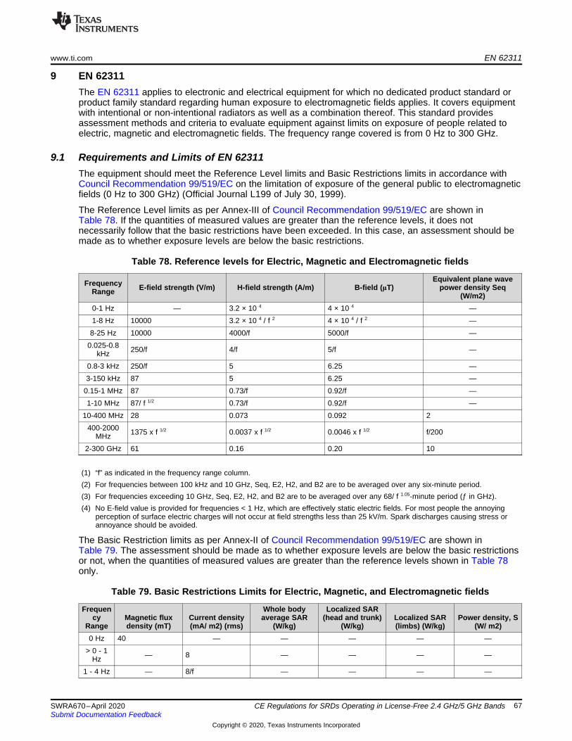
www.ti.com EN 62311
67SWRA670–April 2020Submit Documentation Feedback
Copyright © 2020, Texas Instruments Incorporated
CE Regulations for SRDs Operating in License-Free 2.4 GHz/5 GHz Bands
9 EN 62311The EN 62311 applies to electronic and electrical equipment for which no dedicated product standard orproduct family standard regarding human exposure to electromagnetic fields applies. It covers equipmentwith intentional or non-intentional radiators as well as a combination thereof. This standard providesassessment methods and criteria to evaluate equipment against limits on exposure of people related toelectric, magnetic and electromagnetic fields. The frequency range covered is from 0 Hz to 300 GHz.
9.1 Requirements and Limits of EN 62311The equipment should meet the Reference Level limits and Basic Restrictions limits in accordance withCouncil Recommendation 99/519/EC on the limitation of exposure of the general public to electromagneticfields (0 Hz to 300 GHz) (Official Journal L199 of July 30, 1999).
The Reference Level limits as per Annex-III of Council Recommendation 99/519/EC are shown inTable 78. If the quantities of measured values are greater than the reference levels, it does notnecessarily follow that the basic restrictions have been exceeded. In this case, an assessment should bemade as to whether exposure levels are below the basic restrictions.
Table 78. Reference levels for Electric, Magnetic and Electromagnetic fields
FrequencyRange E-field strength (V/m) H-field strength (A/m) B-field (μT)
Equivalent plane wavepower density Seq
(W/m2)0-1 Hz — 3.2 × 10 4 4 × 10 4 —1-8 Hz 10000 3.2 × 10 4 / f 2 4 × 10 4 / f 2 —8-25 Hz 10000 4000/f 5000/f —
0.025-0.8kHz 250/f 4/f 5/f —
0.8-3 kHz 250/f 5 6.25 —3-150 kHz 87 5 6.25 —
0.15-1 MHz 87 0.73/f 0.92/f —1-10 MHz 87/ f 1/2 0.73/f 0.92/f —
10-400 MHz 28 0.073 0.092 2400-2000
MHz 1375 x f 1/2 0.0037 x f 1/2 0.0046 x f 1/2 f/200
2-300 GHz 61 0.16 0.20 10
(1) “f” as indicated in the frequency range column.(2) For frequencies between 100 kHz and 10 GHz, Seq, E2, H2, and B2 are to be averaged over any six-minute period.(3) For frequencies exceeding 10 GHz, Seq, E2, H2, and B2 are to be averaged over any 68/ f 1.05-minute period (ƒ in GHz).(4) No E-field value is provided for frequencies < 1 Hz, which are effectively static electric fields. For most people the annoying
perception of surface electric charges will not occur at field strengths less than 25 kV/m. Spark discharges causing stress orannoyance should be avoided.
The Basic Restriction limits as per Annex-II of Council Recommendation 99/519/EC are shown inTable 79. The assessment should be made as to whether exposure levels are below the basic restrictionsor not, when the quantities of measured values are greater than the reference levels shown in Table 78only.
Table 79. Basic Restrictions Limits for Electric, Magnetic, and Electromagnetic fields
Frequency
RangeMagnetic fluxdensity (mT)
Current density(mA/ m2) (rms)
Whole bodyaverage SAR
(W/kg)
Localized SAR(head and trunk)
(W/kg)Localized SAR(limbs) (W/kg)
Power density, S(W/ m2)
0 Hz 40 — — — — —> 0 - 1
Hz — 8 — — — —
1 - 4 Hz — 8/f — — — —

EN 62311 www.ti.com
68 SWRA670–April 2020Submit Documentation Feedback
Copyright © 2020, Texas Instruments Incorporated
CE Regulations for SRDs Operating in License-Free 2.4 GHz/5 GHz Bands
Table 79. Basic Restrictions Limits for Electric, Magnetic, and Electromagnetic fields (continued)Frequen
cyRange
Magnetic fluxdensity (mT)
Current density(mA/ m2) (rms)
Whole bodyaverage SAR
(W/kg)
Localized SAR(head and trunk)
(W/kg)Localized SAR(limbs) (W/kg)
Power density, S(W/ m2)
4 - 1000Hz — 2 — — — —
1000Hz – 100
KHz— f/500 — — — —
100kHz – 10
MHz— f/500 0.08 2 4 —
10MHz –10 GHz
— — 0.08 2 4 —
10 - 300GHz — — — — — 10
(1) “f” is the frequency in Hz.(2) The basic restriction on the current density is intended to protect against acute exposure effects on central nervous system
tissues in the head and trunk of the body and includes a safety factor. The basic restrictions for ELF fields are based onestablished adverse effects on the central nervous system. Such acute effects are essentially instantaneous and there is noscientific justification to modify the basic restrictions for exposure of short duration. However, since the basic restriction refers toadverse effects on the central nervous system, this basic restriction may permit higher current densities in body tissues otherthan the central nervous system under the same exposure conditions.
(3) Because of electrical inhomogeneity of the body, current densities should be averaged over a cross section of 1 cm2perpendicular to the current direction.
(4) For frequencies up to 100 kHz, peak current density values can be obtained by multiplying the rms value by √2 (=1,414). Forpulses of duration tp the equivalent frequency to apply in the basic restrictions should be calculated as ƒ = 1/(2tp).
(5) For frequencies up to 100 kHz and for pulsed magnetic fields, the maximum current density associated with the pulses can becalculated from the rise/fall times and the maximum rate of change of magnetic flux density. The induced current density canthen be compared with the appropriate basic restriction.
(6) All SAR values are to be averaged over any six-minute period.(7) Localized SAR averaging mass is any 10g of contiguous tissue; the maximum SAR so obtained should be the value used for
the estimation of exposure. These 10g of tissue are intended to be a mass of contiguous tissue with nearly homogeneouselectrical properties. In specifying a contiguous mass of tissue, it is recognized that this concept can be used in computationaldosimetry but may present difficulties for direct physical measurements. A simple geometry such as cubic tissue mass can beused provided that the calculated dosimetric quantities have conservative values relative to the exposure guidelines.
(8) For pulses of duration tp the equivalent frequency to apply in the basic restrictions should be calculated as ƒ = 1/(2tp).Additionally, for pulsed exposures, in the frequency range 0.3 to 10 GHz and for localized exposure of the head, in order to limitand avoid auditory effects caused by thermoelastic expansion, an additional basic restriction is recommended. This is that theSA should not exceed 2mJ kg–1 averaged over 10 g of tissue.
www.ti.com References
69SWRA670–April 2020Submit Documentation Feedback
Copyright © 2020, Texas Instruments Incorporated
CE Regulations for SRDs Operating in License-Free 2.4 GHz/5 GHz Bands
10 References1. ETSI EN 300 440 V2.2.1 (2018-07)2. ETSI EN 300 328 V2.2.2 (2019-07)3. ETSI EN 301 893 V2.1.1 (2017-05)4. ETSI EN301 489-1 V2.2.1 (2019-03)5. ETSI EN 301 489-17 V3.2.2 (2019-12)6. ETSI EN 300 761-2 V1.1.1 (2001-06)7. ETSI EN 300 683 V1.2.1 (1999-07)8. IEC 62368-19. ERC Recommendation 70-0310. ECO Documentation Database11. RED (Radio Equipment Directive)12. CENELEC EN 5503213. CENELEC EN 50561-114. CENELEC EN 50561-315. CENELEC EN 61000-616. ETSI TR 101 65117. ISO 7637-218. IEC 61000-319. CENELEC EN 61000-420. ISO 7637-221. EN 6231122. Council Recommendation 1999/519/EC23. Regulation (EC) No 765/200824. Regulation (EU) 2017/1354

IMPORTANT NOTICE AND DISCLAIMER
TI PROVIDES TECHNICAL AND RELIABILITY DATA (INCLUDING DATASHEETS), DESIGN RESOURCES (INCLUDING REFERENCE DESIGNS), APPLICATION OR OTHER DESIGN ADVICE, WEB TOOLS, SAFETY INFORMATION, AND OTHER RESOURCES “AS IS” AND WITH ALL FAULTS, AND DISCLAIMS ALL WARRANTIES, EXPRESS AND IMPLIED, INCLUDING WITHOUT LIMITATION ANY IMPLIED WARRANTIES OF MERCHANTABILITY, FITNESS FOR A PARTICULAR PURPOSE OR NON-INFRINGEMENT OF THIRD PARTY INTELLECTUAL PROPERTY RIGHTS.These resources are intended for skilled developers designing with TI products. You are solely responsible for (1) selecting the appropriate TI products for your application, (2) designing, validating and testing your application, and (3) ensuring your application meets applicable standards, and any other safety, security, or other requirements. These resources are subject to change without notice. TI grants you permission to use these resources only for development of an application that uses the TI products described in the resource. Other reproduction and display of these resources is prohibited. No license is granted to any other TI intellectual property right or to any third party intellectual property right. TI disclaims responsibility for, and you will fully indemnify TI and its representatives against, any claims, damages, costs, losses, and liabilities arising out of your use of these resources.TI’s products are provided subject to TI’s Terms of Sale (www.ti.com/legal/termsofsale.html) or other applicable terms available either on ti.com or provided in conjunction with such TI products. TI’s provision of these resources does not expand or otherwise alter TI’s applicable warranties or warranty disclaimers for TI products.
Mailing Address: Texas Instruments, Post Office Box 655303, Dallas, Texas 75265Copyright © 2020, Texas Instruments Incorporated