ce expansion
TRANSCRIPT
Nokia Siemens Networks WCDMA RAN, Rel. RU10, System Library, v. 6
Expanding the Node B
DN70580546
Issue 1-0Approval Date 2008/08/29
Confidential

2 DN70580546Issue 1-0
Expanding the Node B
Id:0900d80580624b44Confidential
The information in this document is subject to change without notice and describes only the product defined in the introduction of this documentation. This documentation is intended for the use of Nokia Siemens Networks customers only for the purposes of the agreement under which the document is submitted, and no part of it may be used, reproduced, modified or transmitted in any form or means without the prior written permission of Nokia Siemens Networks. The documentation has been prepared to be used by professional and properly trained personnel, and the customer assumes full responsibility when using it. Nokia Siemens Networks welcomes customer comments as part of the process of continuous development and improvement of the documentation.
The information or statements given in this documentation concerning the suitability, capacity, or performance of the mentioned hardware or software products are given "as is" and all liability arising in connection with such hardware or software products shall be defined conclusively and finally in a separate agreement between Nokia Siemens Networks and the customer. However, Nokia Siemens Networks has made all reasonable efforts to ensure that the instructions contained in the document are adequate and free of material errors and omissions. Nokia Siemens Networks will, if deemed necessary by Nokia Siemens Networks, explain issues which may not be covered by the document.
Nokia Siemens Networks will correct errors in this documentation as soon as possible. IN NO EVENT WILL Nokia Siemens Networks BE LIABLE FOR ERRORS IN THIS DOCUMENTA-TION OR FOR ANY DAMAGES, INCLUDING BUT NOT LIMITED TO SPECIAL, DIRECT, INDI-RECT, INCIDENTAL OR CONSEQUENTIAL OR ANY LOSSES, SUCH AS BUT NOT LIMITED TO LOSS OF PROFIT, REVENUE, BUSINESS INTERRUPTION, BUSINESS OPPORTUNITY OR DATA,THAT MAY ARISE FROM THE USE OF THIS DOCUMENT OR THE INFORMATION IN IT.
This documentation and the product it describes are considered protected by copyrights and other intellectual property rights according to the applicable laws.
The wave logo is a trademark of Nokia Siemens Networks Oy. Nokia is a registered trademark of Nokia Corporation. Siemens is a registered trademark of Siemens AG.
Other product names mentioned in this document may be trademarks of their respective owners, and they are mentioned for identification purposes only.
Copyright © Nokia Siemens Networks 2009. All rights reserved
f Important Notice on Product Safety Elevated voltages are inevitably present at specific points in this electrical equipment. Some of the parts may also have elevated operating temperatures.
Non-observance of these conditions and the safety instructions can result in personal injury or in property damage.
Therefore, only trained and qualified personnel may install and maintain the system.
The system complies with the standard EN 60950 / IEC 60950. All equipment connected has to comply with the applicable safety standards.
The same text in German:
Wichtiger Hinweis zur Produktsicherheit
In elektrischen Anlagen stehen zwangsläufig bestimmte Teile der Geräte unter Span-nung. Einige Teile können auch eine hohe Betriebstemperatur aufweisen.
Eine Nichtbeachtung dieser Situation und der Warnungshinweise kann zu Körperverlet-zungen und Sachschäden führen.
Deshalb wird vorausgesetzt, dass nur geschultes und qualifiziertes Personal die Anlagen installiert und wartet.
Das System entspricht den Anforderungen der EN 60950 / IEC 60950. Angeschlossene Geräte müssen die zutreffenden Sicherheitsbestimmungen erfüllen.
DN70580546 Issue 1-0
3
Expanding the Node B
Id:0900d80580624b44Confidential
Table of contentsThis document has 87 pages.
Reason for Update. . . . . . . . . . . . . . . . . . . . . . . . . . . . . . . . . . . . . . . . . . 7
1 Introduction . . . . . . . . . . . . . . . . . . . . . . . . . . . . . . . . . . . . . . . . . . . . . . . 91.1 CE Declaration of Conformity . . . . . . . . . . . . . . . . . . . . . . . . . . . . . . . . . 91.2 Expansion in Terms of Quantity. . . . . . . . . . . . . . . . . . . . . . . . . . . . . . . . 91.3 Cell Configuration Range and Terminology. . . . . . . . . . . . . . . . . . . . . . . 91.4 Expansion Strategy . . . . . . . . . . . . . . . . . . . . . . . . . . . . . . . . . . . . . . . . 101.5 Guidelines . . . . . . . . . . . . . . . . . . . . . . . . . . . . . . . . . . . . . . . . . . . . . . . 131.6 Card/Module Handling Instructions . . . . . . . . . . . . . . . . . . . . . . . . . . . . 131.7 Disposal of Electrical and Electronic Equipment . . . . . . . . . . . . . . . . . . 141.8 Prerequisites . . . . . . . . . . . . . . . . . . . . . . . . . . . . . . . . . . . . . . . . . . . . . 151.8.1 Required Knowledge . . . . . . . . . . . . . . . . . . . . . . . . . . . . . . . . . . . . . . . 151.8.2 Necessary Test Equipment and Documentation . . . . . . . . . . . . . . . . . . 151.8.3 Expansion Parts. . . . . . . . . . . . . . . . . . . . . . . . . . . . . . . . . . . . . . . . . . . 151.9 Symbols used . . . . . . . . . . . . . . . . . . . . . . . . . . . . . . . . . . . . . . . . . . . . 16
2 Task List . . . . . . . . . . . . . . . . . . . . . . . . . . . . . . . . . . . . . . . . . . . . . . . . 172.1 Cell Expansion . . . . . . . . . . . . . . . . . . . . . . . . . . . . . . . . . . . . . . . . . . . . 172.1.1 from TRX-LPA 1/1/1-3x20 W to 2/2/2-6x20 W. . . . . . . . . . . . . . . . . . . . 172.1.2 from DRIC-CAT 1/1/1-3x20(40) W to 2/2/2-6x20(40) W . . . . . . . . . . . . 172.1.3 from DRIC-CAT 2/2/2-6x20 W to 3/3/3-9x20 W. . . . . . . . . . . . . . . . . . . 172.1.4 from DRIC-CAT 1/1/1-3x20 W to 1/1/1-3x40 W. . . . . . . . . . . . . . . . . . . 172.1.5 from DRIC-CAT 2/2/2-6x20 W to 2/2/2-6x40 W. . . . . . . . . . . . . . . . . . . 172.1.6 from DRIC-CAT 1/1/1-3x20 W to 6 Sector 1/1/1/1/1/1-3x20 + 3x12.5 W 172.1.7 from DRIC-CAT 1/1/1-3x40 W to Dual Site 1/1/1 + 1/1/1-3x40 + 3x12.5 W
172.1.8 Ring Exchange TRX-LPA to DRIC-CAT . . . . . . . . . . . . . . . . . . . . . . . . 172.2 DC Power Supply Expansion (NB-441 and NB-881). . . . . . . . . . . . . . . 182.3 Line Interface Expansion/Alteration . . . . . . . . . . . . . . . . . . . . . . . . . . . . 18
3 Procedures . . . . . . . . . . . . . . . . . . . . . . . . . . . . . . . . . . . . . . . . . . . . . . 193.1 Expand TRX-LPA 1/1/1-3x20 W to 2/2/2-6x20 W . . . . . . . . . . . . . . . . . 203.2 Expand DRIC-CAT 1/1/1-3x20(40) W to 2/2/2-6x20(40) W. . . . . . . . . . 243.3 Expand DRIC-CAT 2/2/2-6x20 W to 3/3/3-9x20 W . . . . . . . . . . . . . . . . 283.4 DRIC-CAT from 1/1/1-3x20 W to 1/1/1-3x40 W. . . . . . . . . . . . . . . . . . . 303.5 DRIC-CAT from 2/2/2-6x20 W to 2/2/2-6x40 W. . . . . . . . . . . . . . . . . . . 343.6 Decrease TRX-LPA 1/1/1-3x20 W to 0/0/0 . . . . . . . . . . . . . . . . . . . . . . 393.7 DRIC-CAT from 0/0/0 to 1/1/1-3x20 W . . . . . . . . . . . . . . . . . . . . . . . . . 423.8 DRIC-CAT from 0/0/0 to 2/2/2-6x20 W . . . . . . . . . . . . . . . . . . . . . . . . . 463.9 Adding of 3 Remote Radio Heads (RRHs) . . . . . . . . . . . . . . . . . . . . . . 513.10 Increase DC Power Supply . . . . . . . . . . . . . . . . . . . . . . . . . . . . . . . . . . 543.11 Adding Backup Battery Sets . . . . . . . . . . . . . . . . . . . . . . . . . . . . . . . . . 563.12 Line Interface Expansion . . . . . . . . . . . . . . . . . . . . . . . . . . . . . . . . . . . . 603.13 Line Interface Alteration . . . . . . . . . . . . . . . . . . . . . . . . . . . . . . . . . . . . . 663.14 DRIC Exchange in a 1/1/1 Configuration . . . . . . . . . . . . . . . . . . . . . . . . 723.15 DRIC Exchange in a 2/2/2 Configuration . . . . . . . . . . . . . . . . . . . . . . . . 75
4 DN70580546Issue 1-0
Expanding the Node B
Id:0900d80580624b44Confidential
4 Tables, Lists and Figures . . . . . . . . . . . . . . . . . . . . . . . . . . . . . . . . . . . . 784.1 1/1/1 - 3x20 W with TRX-LPA . . . . . . . . . . . . . . . . . . . . . . . . . . . . . . . . . 784.2 2/2/2 - 6x20 W with TRX-LPA . . . . . . . . . . . . . . . . . . . . . . . . . . . . . . . . . 794.3 1/1/1 - 3x20 W or 3x40 W with DRIC-CAT . . . . . . . . . . . . . . . . . . . . . . . 804.4 2/2/2 - 6x20 W or 6x40 W with DRIC-CAT . . . . . . . . . . . . . . . . . . . . . . . 814.5 1/1/1 + 1/1/1 or 1/1/1/1/1/1 - with DRIC-CAT-RRH. . . . . . . . . . . . . . . . . 824.6 Power Consumption of NB-441 and NB-881 . . . . . . . . . . . . . . . . . . . . . 834.6.1 Total DC Power Consumption Determination . . . . . . . . . . . . . . . . . . . . . 834.6.2 Required Number of AC/DC Modules. . . . . . . . . . . . . . . . . . . . . . . . . . . 854.7 Calculation of Backup Battery Capacity . . . . . . . . . . . . . . . . . . . . . . . . . 864.7.1 Diagram . . . . . . . . . . . . . . . . . . . . . . . . . . . . . . . . . . . . . . . . . . . . . . . . . 864.7.2 Formula. . . . . . . . . . . . . . . . . . . . . . . . . . . . . . . . . . . . . . . . . . . . . . . . . . 87
DN70580546 Issue 1-0
5
Expanding the Node B
Id:0900d80580624b44Confidential
List of figuresFigure 1 Cell Configuration Terminology . . . . . . . . . . . . . . . . . . . . . . . . . . . . . . . . 9Figure 2 DRIC-CAT Cell Configuration Upgrade Path with CAT20 . . . . . . . . . . . 11Figure 3 DRIC-CAT Cell Configuration Upgrade Path with CAT40 . . . . . . . . . . . 11Figure 4 TRX-LPA Cell Configuration Upgrade Path . . . . . . . . . . . . . . . . . . . . . . 12Figure 5 Ring Exchange . . . . . . . . . . . . . . . . . . . . . . . . . . . . . . . . . . . . . . . . . . . 12Figure 6 ESD symbol . . . . . . . . . . . . . . . . . . . . . . . . . . . . . . . . . . . . . . . . . . . . . . 13Figure 7 Used symbols . . . . . . . . . . . . . . . . . . . . . . . . . . . . . . . . . . . . . . . . . . . . 16Figure 8 Cabling for 1/1/1 - 3x20 W with TRX-LPA . . . . . . . . . . . . . . . . . . . . . . . 78Figure 9 Cabling for 2/2/2 - 6x20 W with TRX-LPA . . . . . . . . . . . . . . . . . . . . . . . 79Figure 10 Cabling for 1/1/1 - 3x20 W or 3x40 W with DRIC-CAT . . . . . . . . . . . . . 80Figure 11 Cabling for 2/2/2 - 6x20 W or 6x40 W with DRIC-CAT . . . . . . . . . . . . . 81Figure 12 Cabling for 1/1/1 + 1/1/1 or 1/1/1/1/1/1 - with DRIC-CAT-RRH . . . . . . . 82Figure 13 Diagram for Backup Battery Calculation . . . . . . . . . . . . . . . . . . . . . . . . 86

6 DN70580546Issue 1-0
Expanding the Node B
Id:0900d80580624b44Confidential
List of tablesTable 1 Power Consumption of NB-441 with TRX-LPA (max. [W]) . . . . . . . . . . 83Table 2 Power Consumption of NB-441/NB-881 with DRIC-CAT (max. [W]) . . . 84

DN70580546 Issue 1-0
7
Expanding the Node B Reason for Update
Id:0900d8058022f6aeConfidential
Reason for UpdateIssue History
Issue Date Summary
01 08/2008 First issue for new release

8 DN70580546Issue 1-0
Expanding the Node B
Id:0900d8058022f6aeConfidential
Reason for Update
DN70580546 Issue 1-0
9
Expanding the Node B Introduction
Id:0900d8058022f680Confidential
1 Introductiong This document is prepared as a standard edition that may include descriptions not
applicable to your system.
1.1 CE Declaration of Conformity
1.2 Expansion in Terms of QuantityExpansion involves the installation of additional racks/shelters, frames, cables and cards/modules, allowing the customer to increase the capacity of a Node B in terms of the number of users and the range of coverage of a sector/cell.
The expansion work to be done at the Node B is described in the form of procedures.
The decision to expand a Node B is normally taken by the operator and the expansion work at the Node B is also carried out by the operator.
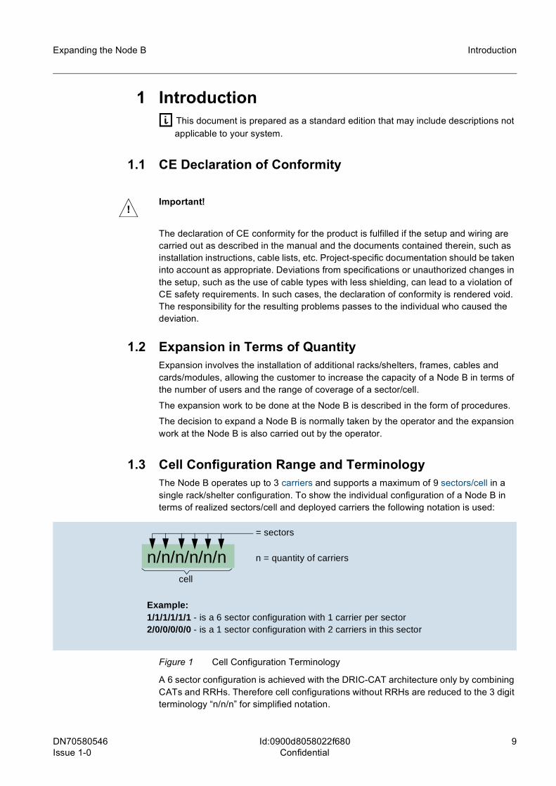
1.3 Cell Configuration Range and TerminologyThe Node B operates up to 3 carriers and supports a maximum of 9 sectors/cell in a single rack/shelter configuration. To show the individual configuration of a Node B in terms of realized sectors/cell and deployed carriers the following notation is used:
Figure 1 Cell Configuration Terminology
A 6 sector configuration is achieved with the DRIC-CAT architecture only by combining CATs and RRHs. Therefore cell configurations without RRHs are reduced to the 3 digit terminology “n/n/n” for simplified notation.
!Important!
The declaration of CE conformity for the product is fulfilled if the setup and wiring are carried out as described in the manual and the documents contained therein, such as installation instructions, cable lists, etc. Project-specific documentation should be taken into account as appropriate. Deviations from specifications or unauthorized changes in the setup, such as the use of cable types with less shielding, can lead to a violation of CE safety requirements. In such cases, the declaration of conformity is rendered void. The responsibility for the resulting problems passes to the individual who caused the deviation.
n/n/n/n/n/n
= sectors
n = quantity of carriers
Example:1/1/1/1/1/1 - is a 6 sector configuration with 1 carrier per sector2/0/0/0/0/0 - is a 1 sector configuration with 2 carriers in this sector
cell
10 DN70580546Issue 1-0
Expanding the Node B
Id:0900d8058022f680Confidential
Introduction
The radio communications capability of a Node B is strongly related with the number of available sectors/cell and carriers. In addition the provided output power of a carrier influences the range of a cell.
According to the “Planning Manual for UMTS Macro Node B 2nd HW-Platform” it can be distinguished between several standard configurations (model units using LPAs) to satisfy particular requirements concerning range and capacity of a cell.
For example:
1/1/1 and 3 x 20 W (High Power)Each sector is supplied by a single LPA and hence the output power of each sector is to the full level of the LPA.
Characteristics: • 1/1/1 with 3 x 20 W • Enables full capacity in one carrier • 16 x E1/J1/T1 lines and 96 channel elements • Excellent coverage • Easy to upgrade to Dual Carrier
2/2/2 and 6 x 20 W (Dual Power)The Dual Power is a completely configured Node B in a 2/2/2 configuration with an output power of 20 W per sector and carrier. This enables the full capacity in a two carrier cell.
Characteristics: • 2/2/2 with 6 x 20 W • High capacity in two carriers • 16 x E1/J1/T1 lines and 288 channel elements
For DRIC-CAT configurations the range of sector/cell and carrier output power combi-nations is even multifaceted and not defined in model units anymore. A selection of rea-sonable configurations and their expansion steps is listed in the “Task List” and performed in the chapter “Procedures”.
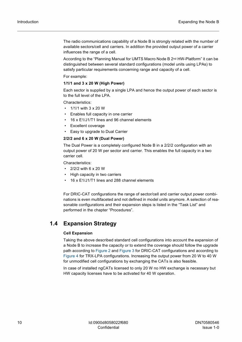
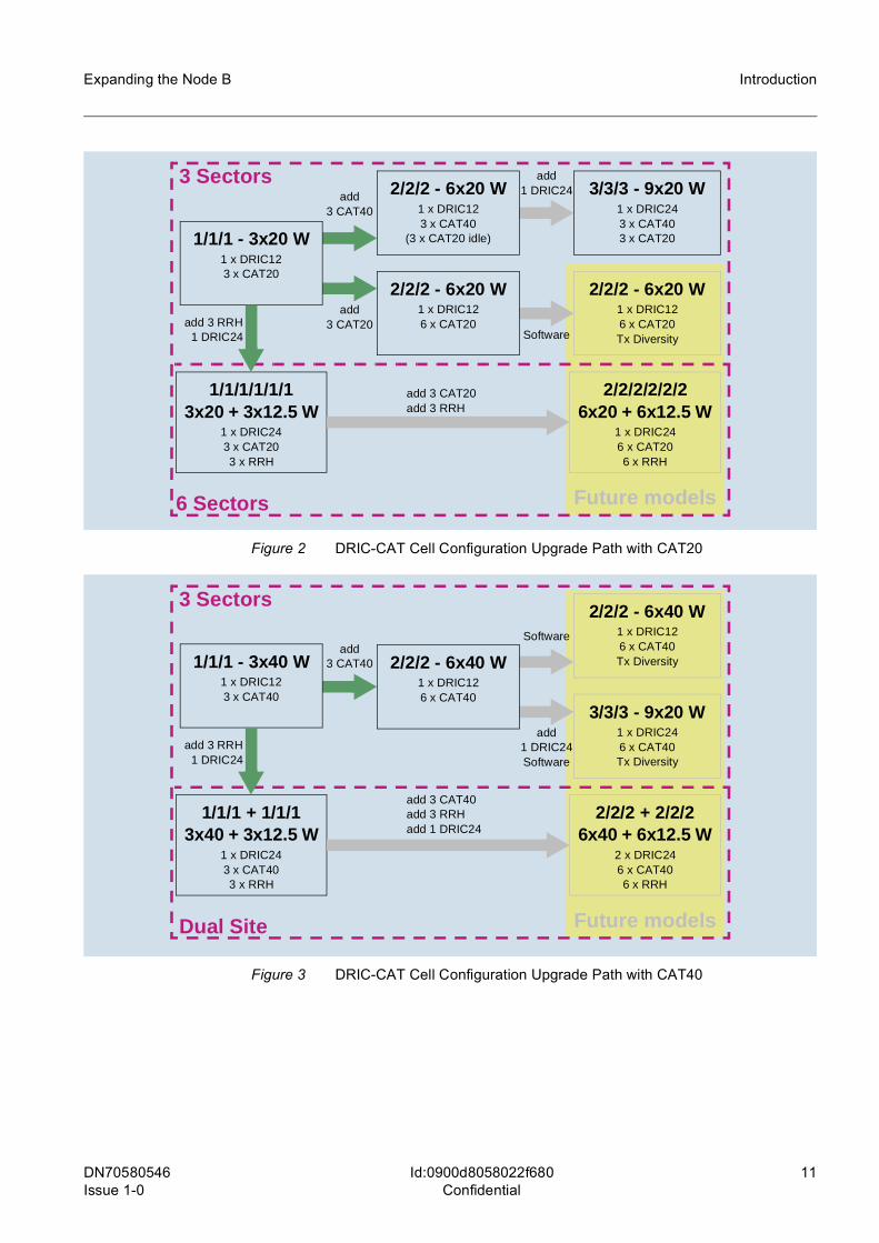
1.4 Expansion StrategyCell ExpansionTaking the above described standard cell configurations into account the expansion of a Node B to increase the capacity or to extend the coverage should follow the upgrade path according to Figure 2 and Figure 3 for DRIC-CAT configurations and according to Figure 4 for TRX-LPA configurations. Increasing the output power from 20 W to 40 W for unmodified cell configurations by exchanging the CATs is also feasible.
In case of installed ngCATs licensed to only 20 W no HW exchange is necessary but HW capacity licenses have to be activated for 40 W operation.
DN70580546 Issue 1-0
11
Expanding the Node B Introduction
Id:0900d8058022f680Confidential
Figure 2 DRIC-CAT Cell Configuration Upgrade Path with CAT20
Figure 3 DRIC-CAT Cell Configuration Upgrade Path with CAT40
Future models
2/2/2 - 6x20 W1 x DRIC123 x CAT40
(3 x CAT20 idle)
3/3/3 - 9x20 W1 x DRIC243 x CAT403 x CAT20
1/1/1/1/1/13x20 + 3x12.5 W
1 x DRIC243 x CAT203 x RRH
2/2/2 - 6x20 W1 x DRIC126 x CAT20Tx Diversity
1/1/1 - 3x20 W1 x DRIC123 x CAT20
2/2/2 - 6x20 W1 x DRIC126 x CAT20
2/2/2/2/2/26x20 + 6x12.5 W
1 x DRIC246 x CAT206 x RRH
add3 CAT40
add3 CAT20
add1 DRIC24
Software
add 3 CAT20add 3 RRH
add 3 RRH1 DRIC24
6 Sectors
3 Sectors
Future models
2/2/2 - 6x40 W1 x DRIC126 x CAT40Tx Diversity
1/1/1 + 1/1/13x40 + 3x12.5 W
1 x DRIC243 x CAT403 x RRH
3/3/3 - 9x20 W1 x DRIC246 x CAT40Tx Diversity
1/1/1 - 3x40 W1 x DRIC123 x CAT40
2/2/2 - 6x40 W1 x DRIC126 x CAT40
2/2/2 + 2/2/26x40 + 6x12.5 W
2 x DRIC246 x CAT406 x RRH
add3 CAT40
add1 DRIC24Software
Software
add 3 CAT40add 3 RRHadd 1 DRIC24
add 3 RRH1 DRIC24
3 Sectors
Dual Site
12 DN70580546Issue 1-0
Expanding the Node B
Id:0900d8058022f680Confidential
Introduction
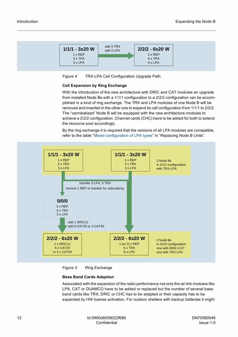
Figure 4 TRX-LPA Cell Configuration Upgrade Path
Cell Expansion by Ring ExchangeWith the introduction of the new architecture with DRIC and CAT modules an upgrade from installed Node Bs with a 1/1/1 configuration to a 2/2/2 configuration can be accom-plished in a kind of ring exchange. The TRX and LPA modules of one Node B will be removed and inserted in the other one to expand its cell configuration from 1/1/1 to 2/2/2. The “cannibalized” Node B will be equipped with the new architecture modules to achieve a 2/2/2 configuration. Channel cards (CHC) have to be added for both to extend the resource pool accordingly.
By the ring exchange it is required that the versions of all LPA modules are compatible, refer to the table “Mixed configuration of LPA types” in “Replacing Node B Units”.
Figure 5 Ring Exchange
Base Band Cards AdaptionAssociated with the expansion of the radio performance not only the air link modules like LPA, CAT or DUAMCO have to be added or replaced but the number of several base band cards like TRX, DRIC or CHC has to be adapted or their capacity has to be expanded by HW license activation. For outdoor shelters with backup batteries it might
1/1/1 - 3x20 W1 x REP3 x TRX3 x LPA
2/2/2 - 6x20 W1 x REP6 x TRX6 x LPA
add 3 TRXadd 3 LPA
2 Node Bsin 1/1/1 configurationwith TRX-LPA
2 Node Bsin 2/2/2 configurationone with DRIC-CATone with TRX-LPA
transfer 3 LPA, 3 TRX
remove 1 REP or transfer for redundancy
add 1 DRIC12add 6 CAT20 or 3 CAT40
1/1/1 - 3x20 W1 x REP3 x TRX3 x LPA
1/1/1 - 3x20 W1 x REP3 x TRX3 x LPA
0/0/00 x REP0 x TRX0 x LPA
2/2/2 - 6x20 W1 x DRIC126 x CAT20
or 3 x CAT40
2/2/2 - 6x20 W1 (or 2) x REP
6 x TRX6 x LPA
DN70580546 Issue 1-0
13
Expanding the Node B Introduction
Id:0900d8058022f680Confidential
also be necessary to extend the DC power supply and to add one or more battery packs in order to keep the backup time on the required level. If appropriate the line interface can also be changed to provide other types of interfaces.
DC Power Supply IncreaseIn consequence of an increased power consumption due to added components in the Node B the DC power supply of the NB-441 or NB-881 must be extended accordingly.
Backup Battery ExpansionApart from the cell expansion and the retention of the backup time an increase can also be required for any other reason. Backup batteries are available in packs of 4 providing a capacity of 92 Ah at 48 V. Calculating the total power consumption of a Node B and determine the desired backup time the number of necessary battery packs can be eval-uated. Eventually additional service shelters have to be installed for housing the backup battery packs.
Line Interface AlterationThe line interface is the physical connection to the RNC. There are different interfaces available (E1/J1/T1; STM-1/OC-3). An expansion of the line interface ability is done by a replacement of the initial installed card by another one with more or even other inter-faces.
1.5 GuidelinesThis manual deals with the expansion of already installed Node Bs. Following the upgrade path (see Figure 4) and (see Figure 2), the tasks to be performed for each upgrade step are different. Therefore each single task is described in a own procedure which is organized in steps. All necessary procedures for one complete expansion grade are summarized in a task group (see chapter 2 "Task List") with references to the relevant procedures and in the right order.
In principle three main worksteps have to be executed: • Adding or replacing cards/modules • Rearranging the system cabling • Modifying the database
After a reset the Node B will go in service with the new configuration.
1.6 Card/Module Handling InstructionsESD PrecautionsAll cards/modules are equipped with electrostatically sensitive components (ESD symbol). Therefore, ESD precautions must be taken when pulling and inserting cards/modules.
Figure 6 ESD symbol
14 DN70580546Issue 1-0
Expanding the Node B
Id:0900d8058022f680Confidential
Introduction
During card/module replacement, personnel must wear a conductive wrist strap to dis-charge electrostatic charging. Before cards/modules, lines or components are touched, this wrist strap must be connected to the ground potential of the rack/shelter by means of a flexible lead integrating a 1 MOhm resistor. Note that the conducting parts of the split pin or the clamp should not be touched when inserting/connecting (so as to avoid bypassing the 1 MOhm resistor).
Pulling and inserting cards/modulesThe replacement requires for some components special tools like torque wrenches, torx screwdrivers or an extractor tool. Many cards can be removed or inserted after swivel-ling the levers at the top and bottom edges.
1.7 Disposal of Electrical and Electronic Equipment
All electrical and electronic products should be disposed of separately from the munici-pal waste stream via designated collection facilities appointed by the government or the local authorities.
The correct disposal and separate collection of your old appliance will help prevent potential negative consequences for the environment and human health. It is a precon-dition for reuse and recycling of used electrical and electronic equipment.
For more detailed information about disposal of your old appliance, please contact your sales representative.
The statements quoted above are only fully valid for equipment which is installed in the countries of the European Union and is covered by the directive 2002/96/EC.
Countries outside the European Union may have other regulations regarding the disposal of electrical and electronic equipment.
DN70580546 Issue 1-0
15
Expanding the Node B Introduction
Id:0900d8058022f680Confidential
1.8 Prerequisites
1.8.1 Required KnowledgeOnly trained personnel should carry out the expansion tasks.
The following personnel requirements must be fulfilled for modifying the system:
• Training to service technician level or equivalent training in communications engi-neering
• Basic knowledge of transmission systems • Appropriate, device related training by the manufacturer, which comprises the
required device and system knowledge for the planned activity • Detailed knowledge in handling and editing XML files • Knowledge relating to LAN / WAN • Basic knowledge of measurement systems • Knowledge of handling electrostatic-sensitive devices • Knowledge of handling optical fibers and laser light sources
1.8.2 Necessary Test Equipment and DocumentationSeveral devices, instruments, accessories and tools must be provided and prepared for expansion on site.
The UTRAN operating documentation is available either on CD-ROM or installed on the LMT consistent with the release in use.
For the Node B the following hardware is required: • PC (laptop) as local maintenance terminal, e.g. LifeBook E or S series
(respectively any other according to the required features listed in the User Guide “Using Node B Service Terminal”)– with Ethernet interface
• Ethernet cable (x-connect)
The following tools are recommended: • Standard toolkit
In addition several software tools are mandatory: • LMT-SW (Basic or Extended) • IDF-Editor • CD with the required Node B SW loads
Further software tools for database editing, only if Basic LMT is applied: • XML-Editor • MIB-Generator • MIB-Checker • MIB-Upgrader
1.8.3 Expansion PartsFor a fast and reliable expansion of the Node B it is essential to have the necessary parts with the right functional state of hardware and firmware.
16 DN70580546Issue 1-0
Expanding the Node B
Id:0900d8058022f680Confidential
Introduction
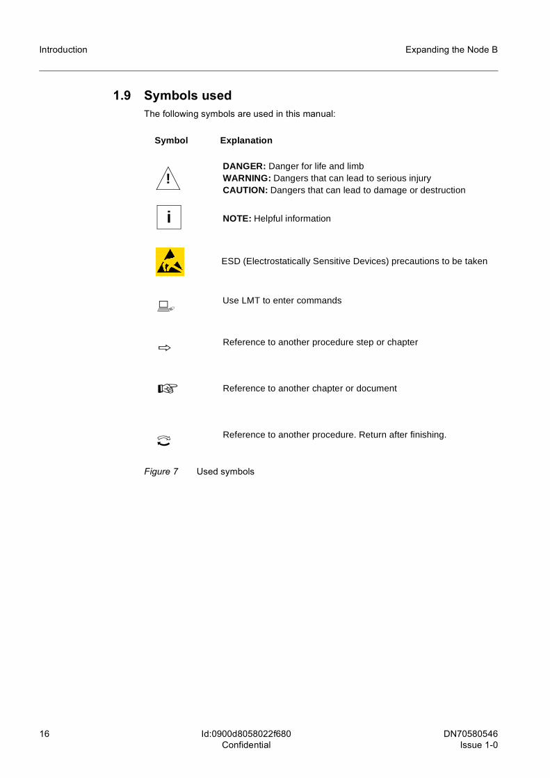
1.9 Symbols usedThe following symbols are used in this manual:
Figure 7 Used symbols
Reference to another procedure step or chapter
Symbol Explanation
ESD (Electrostatically Sensitive Devices) precautions to be taken
b
h
Use LMT to enter commands
☞ Reference to another chapter or document
Reference to another procedure. Return after finishing.i
i
!DANGER: Danger for life and limbWARNING: Dangers that can lead to serious injuryCAUTION: Dangers that can lead to damage or destruction
NOTE: Helpful information
DN70580546 Issue 1-0
17
Expanding the Node B Task List
Id:0900d8058022f682Confidential
2 Task List
2.1 Cell Expansion
2.1.1 from TRX-LPA 1/1/1-3x20 W to 2/2/2-6x20 WTRX-LPA High Power -> Dual Power . . . . . . . . . . . . . . . . . . . . . . . . . . . . . . . . . . 3.1Increase DC power supply (NB-441 and NB-881) . . . . . . . . . . . . . . . . . . . . . . . 3.10Backup battery expansion (NB-441 and NB-881) . . . . . . . . . . . . . . . . . . . . . . . . 3.11
2.1.2 from DRIC-CAT 1/1/1-3x20(40) W to 2/2/2-6x20(40) WDRIC-CAT 3x20(40) W -> 6x20(40) W . . . . . . . . . . . . . . . . . . . . . . . . . . . . . . . . . 3.2Increase DC power supply (NB-441 and NB-881) . . . . . . . . . . . . . . . . . . . . . . . 3.10Backup battery expansion (NB-441 and NB-881) . . . . . . . . . . . . . . . . . . . . . . . . 3.11
2.1.3 from DRIC-CAT 2/2/2-6x20 W to 3/3/3-9x20 WDRIC Exchange in a 2/2/2 configuration . . . . . . . . . . . . . . . . . . . . . . . . . . . . . . . 3.15DRIC-CAT 6x20 W -> 9x20 W . . . . . . . . . . . . . . . . . . . . . . . . . . . . . . . . . . . . . . . 3.3
2.1.4 from DRIC-CAT 1/1/1-3x20 W to 1/1/1-3x40 WDRIC-CAT 3x20 W -> 3x40 W . . . . . . . . . . . . . . . . . . . . . . . . . . . . . . . . . . . . . . . 3.4Increase DC power supply (NB-441 and NB-881) . . . . . . . . . . . . . . . . . . . . . . . 3.10Backup battery expansion (NB-441 and NB-881) . . . . . . . . . . . . . . . . . . . . . . . . 3.11
2.1.5 from DRIC-CAT 2/2/2-6x20 W to 2/2/2-6x40 WDRIC-CAT 6x20 W -> 6x40 W . . . . . . . . . . . . . . . . . . . . . . . . . . . . . . . . . . . . . . . 3.5Increase DC power supply (NB-441 and NB-881) . . . . . . . . . . . . . . . . . . . . . . . 3.10Backup battery expansion (NB-441 and NB-881) . . . . . . . . . . . . . . . . . . . . . . . . 3.11
2.1.6 from DRIC-CAT 1/1/1-3x20 W to 6 Sector 1/1/1/1/1/1-3x20 + 3x12.5 WDRIC Exchange in a 1/1/1 configuration . . . . . . . . . . . . . . . . . . . . . . . . . . . . . . . 3.14Adding 3 RRHs . . . . . . . . . . . . . . . . . . . . . . . . . . . . . . . . . . . . . . . . . . . . . . . . . . . 3.9
2.1.7 from DRIC-CAT 1/1/1-3x40 W to Dual Site 1/1/1 + 1/1/1-3x40 + 3x12.5 WDRIC Exchange in a 1/1/1 configuration . . . . . . . . . . . . . . . . . . . . . . . . . . . . . . . 3.14Adding 3 RRHs . . . . . . . . . . . . . . . . . . . . . . . . . . . . . . . . . . . . . . . . . . . . . . . . . . . 3.9
2.1.8 Ring Exchange TRX-LPA to DRIC-CAT
Cannibalize one TRX-LPA 1/1/1-3x20 W to expand another to 2/2/2-6x20 WDecrease TRX-LPA 1/1/1-3x20 W to 0/0/0 . . . . . . . . . . . . . . . . . . . . . . . . . . . . . . 3.6TRX-LPA High Power -> Dual Power . . . . . . . . . . . . . . . . . . . . . . . . . . . . . . . . . . 3.1Increase DC power supply (NB-441 and NB-881) . . . . . . . . . . . . . . . . . . . . . . . 3.10Backup battery expansion (NB-441 and NB-881) . . . . . . . . . . . . . . . . . . . . . . . . 3.11
18 DN70580546Issue 1-0
Expanding the Node B
Id:0900d8058022f682Confidential
Task List
Configure a cannibalized Node B with new DRIC-CAT architectureDRIC-CAT from 0/0/0 to 1/1/1-3x20 W . . . . . . . . . . . . . . . . . . . . . . . . . . . . . . . . . . 3.7or . . . . . . . . . . . . . . . . . . . . . . . . . . . . . . . . . . . . . . . . . . . . . . . . . . . . . . . . DRIC-CAT from 0/0/0 to 2/2/2-6x20 W . . . . . . . . . . . . . . . . . . . . . . . . . . . . . . . . . . 3.8Increase DC power supply (NB-441 and NB-881) . . . . . . . . . . . . . . . . . . . . . . . . 3.10Backup battery expansion (NB-441 and NB-881) . . . . . . . . . . . . . . . . . . . . . . . . 3.11
2.2 DC Power Supply Expansion (NB-441 and NB-881)Increase DC power supply (NB-441 and NB-881) . . . . . . . . . . . . . . . . . . . . . . . . 3.10Backup battery expansion (NB-441 and NB-881) . . . . . . . . . . . . . . . . . . . . . . . . 3.11
2.3 Line Interface Expansion/Alteration8 x E1/J1/T1 -> 16 x E1/J1/T1 with or without 2 x STM-1/OC-3 . . . . . . . . . . . . . . 3.1216 x E1/J1/T1 -> 16 x E1/J1/T1 + 2 x STM-1/OC-3 . . . . . . . . . . . . . . . . . . . . . . . 3.13

DN70580546 Issue 1-0
19
Expanding the Node B Procedures
Id:0900d8058022f6a0Confidential
3 Procedures
20 DN70580546Issue 1-0
Expanding the Node B
Id:0900d8058022f6a0Confidential
Procedures
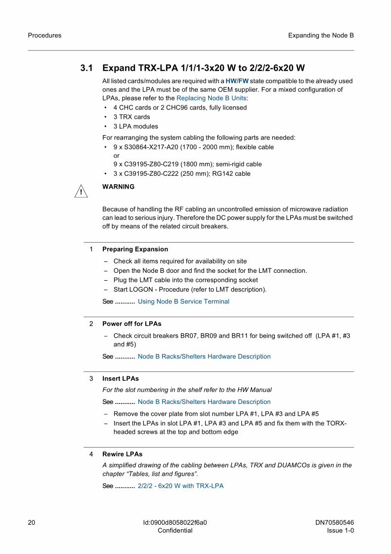
3.1 Expand TRX-LPA 1/1/1-3x20 W to 2/2/2-6x20 WAll listed cards/modules are required with a HW/FW state compatible to the already used ones and the LPA must be of the same OEM supplier. For a mixed configuration of LPAs, please refer to the Replacing Node B Units: • 4 CHC cards or 2 CHC96 cards, fully licensed • 3 TRX cards • 3 LPA modules
For rearranging the system cabling the following parts are needed: • 9 x S30864-X217-A20 (1700 - 2000 mm); flexible cable
or9 x C39195-Z80-C219 (1800 mm); semi-rigid cable
• 3 x C39195-Z80-C222 (250 mm); RG142 cable
1 Preparing Expansion
– Check all items required for availability on site– Open the Node B door and find the socket for the LMT connection.– Plug the LMT cable into the corresponding socket– Start LOGON - Procedure (refer to LMT description).
See ........... Using Node B Service Terminal
2 Power off for LPAs
– Check circuit breakers BR07, BR09 and BR11 for being switched off (LPA #1, #3 and #5)
See ........... Node B Racks/Shelters Hardware Description
3 Insert LPAsFor the slot numbering in the shelf refer to the HW Manual
See ........... Node B Racks/Shelters Hardware Description
– Remove the cover plate from slot number LPA #1, LPA #3 and LPA #5– Insert the LPAs in slot LPA #1, LPA #3 and LPA #5 and fix them with the TORX-
headed screws at the top and bottom edge
4 Rewire LPAsA simplified drawing of the cabling between LPAs, TRX and DUAMCOs is given in the chapter “Tables, list and figures”.
See ........... 2/2/2 - 6x20 W with TRX-LPA
!WARNING
Because of handling the RF cabling an uncontrolled emission of microwave radiation can lead to serious injury. Therefore the DC power supply for the LPAs must be switched off by means of the related circuit breakers.
DN70580546 Issue 1-0
21
Expanding the Node B Procedures
Id:0900d8058022f6a0Confidential
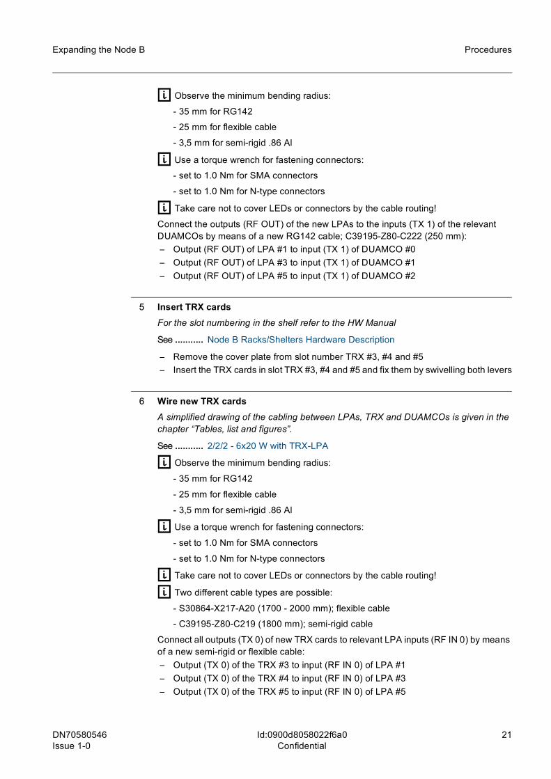
g Observe the minimum bending radius:
- 35 mm for RG142
- 25 mm for flexible cable
- 3,5 mm for semi-rigid .86 Al
g Use a torque wrench for fastening connectors:
- set to 1.0 Nm for SMA connectors
- set to 1.0 Nm for N-type connectors
g Take care not to cover LEDs or connectors by the cable routing!
Connect the outputs (RF OUT) of the new LPAs to the inputs (TX 1) of the relevant DUAMCOs by means of a new RG142 cable; C39195-Z80-C222 (250 mm):– Output (RF OUT) of LPA #1 to input (TX 1) of DUAMCO #0– Output (RF OUT) of LPA #3 to input (TX 1) of DUAMCO #1– Output (RF OUT) of LPA #5 to input (TX 1) of DUAMCO #2
5 Insert TRX cardsFor the slot numbering in the shelf refer to the HW Manual
See ........... Node B Racks/Shelters Hardware Description
– Remove the cover plate from slot number TRX #3, #4 and #5– Insert the TRX cards in slot TRX #3, #4 and #5 and fix them by swivelling both levers
6 Wire new TRX cardsA simplified drawing of the cabling between LPAs, TRX and DUAMCOs is given in the chapter “Tables, list and figures”.
See ........... 2/2/2 - 6x20 W with TRX-LPA
g Observe the minimum bending radius:
- 35 mm for RG142
- 25 mm for flexible cable
- 3,5 mm for semi-rigid .86 Al
g Use a torque wrench for fastening connectors:
- set to 1.0 Nm for SMA connectors
- set to 1.0 Nm for N-type connectors
g Take care not to cover LEDs or connectors by the cable routing!
g Two different cable types are possible:
- S30864-X217-A20 (1700 - 2000 mm); flexible cable
- C39195-Z80-C219 (1800 mm); semi-rigid cable
Connect all outputs (TX 0) of new TRX cards to relevant LPA inputs (RF IN 0) by means of a new semi-rigid or flexible cable:– Output (TX 0) of the TRX #3 to input (RF IN 0) of LPA #1– Output (TX 0) of the TRX #4 to input (RF IN 0) of LPA #3– Output (TX 0) of the TRX #5 to input (RF IN 0) of LPA #5
22 DN70580546Issue 1-0
Expanding the Node B
Id:0900d8058022f6a0Confidential
Procedures
Connect both inputs (RX 0 and RX 1) of all new TRX cards to the outputs (RX10 and RX01) of the relevant DUAMCOs by means of a new semi-rigid or flexible cable:– Output (RX10) of DUAMCO #0 (ANT1 part) to input (RX 0) of TRX #3– Output (RX01) of DUAMCO #0 (ANT0 part) to input (RX 1) of TRX #3
– Output (RX10) of DUAMCO #1 (ANT1 part) to input (RX 0) of TRX #4– Output (RX01) of DUAMCO #1 (ANT0 part) to input (RX 1) of TRX #4
– Output (RX10) of DUAMCO #2 (ANT1 part) to input (RX 0) of TRX #5– Output (RX01) of DUAMCO #2 (ANT0 part) to input (RX 1) of TRX #5
All connections between the previous present TRX, LPA and DUAMCO modules remain as they are.
7 Insert CHC cardsFor the slot numbering in the shelf refer to the HW Manual
See ........... Node B Racks/Shelters Hardware Description
g The capacity (number of channel elements) of the CHC96 card depends on the acti-vation of the HW capacity licenses!
– Remove the cover plate from slot number CHC #2, CHC #3, CHC #4 and CHC #5, depending on the required amount of CHC cards
– Insert the CHC cards in slot CHC #2, CHC #3, CHC #4 and CHC #5 and fix them by swivelling both levers
8 Power on for LPAs
– Switch on the DC power supply for LPA #1, #3 and #5; circuit breakers BR07, BR09 and BR11 on DC Panel
– Check circuit breakers BR01 to BR05, BR06, BR08 and BR10 for being switched on (for equipped CHCs, TRXs, LPAs, DUAMCOs and FANs)
See ........... Node B Racks/Shelters Hardware Description
9 Update Databaseb Upload the database from Node B using the LMT.
g NOTEIf the extended LMT is used the necessary modifications of the database can be achieved more comfortable by the “Database Management” application, please refer to Using Node B Service Terminal.
Change the database using the MIB-Generator tool to fit the new configuration by entering the following command:
#mibGen -import <nbDatabase> -o <outputDir> -cellCfg 2/2/2/0/0/0
Make the check of the database and update the header file with the MIB-Check tool.
See ........... Node B Database Editing Guide
DN70580546 Issue 1-0
23
Expanding the Node B Procedures
Id:0900d8058022f6a0Confidential
b Download the modified database to the Node B and finally activate the new database by means of the LMT.
A restart of the Node B is performed automatically and the LMT connection to the Node B will be terminated.
g NOTEThe LMT connection has to be re-established after the reboot of the Node B. Other-wise the Node B will revert to the original load after some time if the LMT does not reconnect.
It is recommended to select the “Force Connection Supervision” in the preferences of the LMT application to activate an automatic reconnection to the Node B after the restart, please refer to Using Node B Service Terminal.
10 Update Remote Inventory Data
– Then make a backup copy of the complete inventory data set as an inventory data file (IDF) for storage and forwarding to the inventory system according to the under-lying concept.
11 Terminating activitiesFor a NB-441 or a NB-881 it might be necessary to increase the number of AC/DC modules
See ........... 3.10
or
to expand the backup battery capacity
See ........... 3.11
– Terminate the LMT program (refer to LMT description).– Remove the LMT cable from Node B.– Close the Node B door.
END
24 DN70580546Issue 1-0
Expanding the Node B
Id:0900d8058022f6a0Confidential
Procedures
3.2 Expand DRIC-CAT 1/1/1-3x20(40) W to 2/2/2-6x20(40) WAll listed cards/modules are required with a HW/FW state compatible to the already used ones: • up to 4 CHC or 2 CHC96 cards, fully licensed with the calculation of required
numbers according to PMN-0 • 3 CAT modules (20 W or 40 W)
For rearranging the system cabling the following parts are needed: • 3 x S30864-X230-A53; firewire cable
or6 x S30864-X230-A53; firewire cable (with DRIC in redundancy configuration)
• 3 x C39195-Z80-C222 (250 mm); RG142 cable • 6 x S30864-X217-A35 (240 mm); flexible cable
1 Preparing Expansion
– Check all items required for availability on site– Open the Node B door and find the socket for the LMT connection.– Plug the LMT cable into the corresponding socket– Start LOGON - Procedure (refer to LMT description).
See ........... Using Node B Service Terminal
2 Power off for CATs
– Check circuit breakers BR07, BR09 and BR11 for being switched off (CAT #1, #3 and #5)
See ........... Node B Racks/Shelters Hardware Description
3 Insert CATsFor the slot numbering in the shelf refer to the HW Manual
See ........... Node B Racks/Shelters Hardware Description
– Remove the cover plate from slot number CAT #1, CAT #3 and CAT #5– Insert the CATs in slot CAT #1, CAT #3 and CAT #5 and fix them with the TORX-
headed screws at the top and bottom edge
4 Rewire CATs and DUAMCOsA simplified drawing of the cabling between CATs and DUAMCOs is given in the chapter “Tables, list and figures”.
See ........... 2/2/2 - 6x20 W or 6x40 W with DRIC-CAT
!WARNING:
Because of handling the RF cabling an uncontrolled emission of microwave radiation can lead to serious injury. Therefore the DC power supply for the CATs must be switched off by means of the related circuit breakers.
DN70580546 Issue 1-0
25
Expanding the Node B Procedures
Id:0900d8058022f6a0Confidential
g Observe the minimum bending radius:
- 35 mm for RG142
- 25 mm for flexible cable
g Use a torque wrench for fastening connectors:
- set to 1.0 Nm for SMA connectors
- set to 1.0 Nm for N-type connectors
g Take care not to cover LEDs or connectors by the cable routing!
Connect the outputs (TX OUT) of the new CATs to the inputs (TX 1) of the relevant DUAMCOs by means of a new RG142 cable; C39195-Z80-C222 (250 mm):– Output (TX OUT) of CAT #1 to input (TX 1) of DUAMCO #0– Output (TX OUT) of CAT #3 to input (TX 1) of DUAMCO #1– Output (TX OUT) of CAT #5 to input (TX 1) of DUAMCO #2
Connect the inputs (RX 0) of the new CATs to the outputs (RX 01) of the relevant DUAMCOs by means of a new flexible cable; S30864-X217-A35 (240 mm)):– Input (RX 0) of CAT #1 to output (RX 01) of DUAMCO #0– Input (RX 0) of CAT #3 to output (RX 01) of DUAMCO #1– Input (RX 0) of CAT #5 to output (RX 01) of DUAMCO #2
Connect the inputs (RX 1) of the new CATs to the outputs (RX 11) of the relevant DUAMCOs by means of a new flexible cable; S30864-X217-A35 (240 mm):– Input (RX 1) of CAT #1 to output (RX 11) of DUAMCO #0– Input (RX 1) of CAT #3 to output (RX 11) of DUAMCO #1– Input (RX 1) of CAT #5 to output (RX 11) of DUAMCO #2
5 Wire CATs with DRIC card(s)A simplified drawing of the cabling between CATs and DRIC card(s) is given in the chapter “Tables, list and figures”.
See ........... 2/2/2 - 6x20 W or 6x40 W with DRIC-CAT
g Take care not to cover LEDs or connectors by the cable routing!
Connect the interface (DRIC 0) of the new CAT modules to the DRIC #0 card by means of a new firewire cable S30864-X230-A53:– Interface (DRIC 0) of the CAT #1 to interface (CPRI 1) of DRIC #0– Interface (DRIC 0) of the CAT #3 to interface (CPRI 3) of DRIC #0– Interface (DRIC 0) of the CAT #5 to interface (CPRI 5) of DRIC #0
g With DRIC in redundancy configuration the second DRIC interface on the CAT modules has to be connected to the DRIC #1 card!
Connect the interface (DRIC 1) of the new CAT modules to the DRIC #1 card by means of a new firewire cable S30864-X230-A53:– Interface (DRIC 1) of the CAT #1 to interface (CPRI 1) of DRIC #1– Interface (DRIC 1) of the CAT #3 to interface (CPRI 3) of DRIC #1– Interface (DRIC 1) of the CAT #5 to interface (CPRI 5) of DRIC #1
The interface “CPRI” may also be labeled as “CAT”
26 DN70580546Issue 1-0
Expanding the Node B
Id:0900d8058022f6a0Confidential
Procedures
6 Insert CHC cardsFor the slot numbering in the shelf refer to the HW Manual
See ........... Node B Racks/Shelters Hardware Description
g The capacity (number of channel elements) of the CHC96 card depends on the acti-vation of the HW capacity licenses!
– Remove the cover plate from slot number CHC #2, CHC #3, CHC #4 and CHC #5, depending on the required amount of CHC cards
– Insert the CHC cards in slot CHC #2, CHC #3, CHC #4 and CHC #5 and fix them by swivelling both levers
7 Power on for CATs
– Switch on the DC power supply for CAT #1, #3 and #5; circuit breakers BR07, BR09 and BR11 on DC Panel
– Check circuit breakers BR01 to BR05, BR06, BR08 and BR10 for being switched on (for equipped CHCs, DRICs, CATs, DUAMCOs and FANs)
See ........... Node B Racks/Shelters Hardware Description
8 Update Databaseb Upload the database from Node B using the LMT.
g NOTEIf the extended LMT is used the necessary modifications of the database can be achieved more comfortable by the “Database Management” application, please refer to “Using Node B Service Terminal”.
Change the database using the MIB-Generator tool to fit the new configuration by entering the following command:
#mibGen -import <nbDatabase> -o <outputDir> -cellCfg 2/2/2/0/0/0Make the check of the database and update the header file with the MIB-Check tool.
See ........... Node B Database Editing Guide
b Download the modified database to the Node B and finally activate the new database by means of the LMT.
A restart of the Node B is performed automatically and the LMT connection to the Node B will be terminated.
g NOTEThe LMT connection has to be re-established after the reboot of the Node B. Other-wise the Node B will revert to the original load after some time if the LMT does not reconnect.
It is recommended to select the “Force Connection Supervision” in the preferences of the LMT application to activate an automatic reconnection to the Node B after the restart, please refer to “Using Node B Service Terminal”.

DN70580546 Issue 1-0
27
Expanding the Node B Procedures
Id:0900d8058022f6a0Confidential
9 Update Remote Inventory Data
– Then make a backup copy of the complete inventory data set as an inventory data file (IDF) for storage and forwarding to the inventory system according to the under-lying concept.
10 Terminating activitiesFor a NB-441 or a NB-881 it might be necessary to increase the number of AC/DC modules
See ........... 3.10
or
to expand the backup battery capacity
See ........... 3.11
– Terminate the LMT program (refer to LMT description).– Remove the LMT cable from Node B.– Close the Node B door.
END
28 DN70580546Issue 1-0
Expanding the Node B
Id:0900d8058022f6a0Confidential
Procedures
3.3 Expand DRIC-CAT 2/2/2-6x20 W to 3/3/3-9x20 WAccording to the upgrade path with CAT20 from 1/1/1 to 2/2/2 where 3 x CAT40 are added and the CAT20 are left in idle mode neither CATs have to be installed nor cables have to be rearranged for the expansion to 3/3/3. But the number of channel cards has to be increased and the database must be updated.
The DRIC card must be a DRIC24-24OE.
All listed cards/modules are required with a HW/FW state compatible to the already used ones: • up to 4 CHC or 2 CHC96 cards, fully licensed with the calculation of required
numbers according to PMN-0
1 Preparing Expansion
– Check all items required for availability on site– Open the Node B door and find the socket for the LMT connection.– Plug the LMT cable into the corresponding socket– Start LOGON - Procedure (refer to LMT description).
See ........... Using Node B Service Terminal
2 Insert CHC cardsFor the slot numbering in the shelf refer to the HW Manual
See ........... Node B Racks/Shelters Hardware Description
g The capacity (number of channel elements) of the CHC96 card depends on the acti-vation of the HW capacity licenses!
– Remove the cover plate from slot number CHC #6, CHC #7, CHC #8 and CHC #9, depending on the required amount of CHC cards
– Insert the CHC cards in slot CHC #6, CHC #7, CHC #8 and CHC #9 and fix them by swivelling both levers
3 Update Databaseb Upload the database from Node B using the LMT.
g NOTEIf the extended LMT is used the necessary modifications of the database can be achieved more comfortable by the “Database Management” application, please refer to “Using Node B Service Terminal”.
Change the database using the MIB-Generator tool to fit the new configuration by entering the following command:
#mibGen -import <nbDatabase> -o <outputDir> -cellCfg 3/3/3/0/0/0
Make the check of the database and update the header file with the MIB-Check tool.
See ........... Node B Database Editing Guide
b Download the modified database to the Node B and finally activate the new database by means of the LMT.

DN70580546 Issue 1-0
29
Expanding the Node B Procedures
Id:0900d8058022f6a0Confidential
A restart of the Node B is performed automatically and the LMT connection to the Node B will be terminated.
g NOTEThe LMT connection has to be re-established after the reboot of the Node B. Other-wise the Node B will revert to the original load after some time if the LMT does not reconnect.
It is recommended to select the “Force Connection Supervision” in the preferences of the LMT application to activate an automatic reconnection to the Node B after the restart, please refer to “Using Node B Service Terminal”.
4 Update Remote Inventory Data
– Then make a backup copy of the complete inventory data set as an inventory data file (IDF) for storage and forwarding to the inventory system according to the under-lying concept.
5 Terminating activities
– Terminate the LMT program (refer to LMT description).– Remove the LMT cable from Node B.– Close the Node B door.
END
30 DN70580546Issue 1-0
Expanding the Node B
Id:0900d8058022f6a0Confidential
Procedures
3.4 DRIC-CAT from 1/1/1-3x20 W to 1/1/1-3x40 WThis procedure is intended for the increase of the output power per carrier from 20 W to 40 W in a 1/1/1 configuration with initial installed CAT20. If ngCATs are installed an upgrade to 40 W is achieved by applying appropriate licenses.
All listed cards/modules are required with a compatible HW/FW state: • 3 CAT40 modules
1 Preparing Expansion
– Check all items required for availability on site– All traffic has been terminated– Open the Node B door and find the socket for the LMT connection.– Plug the LMT cable into the corresponding socket– Start LOGON - Procedure (refer to LMT description).
See ........... Using Node B Service Terminal
2 Power off for CATs
– Switch off the DC power supply for CAT #0, CAT #2 and CAT #4; circuit breaker BR06, BR08 and BR10 on DC Panel
See ........... Node B Racks/Shelters Hardware Description
3 Disconnect cabling from CATsA simplified drawing of the cabling between CATs, DRICs and DUAMCOs is given in the chapter “Tables, list and figures”.
See ........... 1/1/1 - 3x20 W or 3x40 W with DRIC-CAT
g NOTEObserve the minimum bending radius:
- 35 mm for RG142
- 25 mm for flexible cable
- 3,5 mm for semi-rigid .86 Al
– Disconnect the RG142 cable S30864-X217-A46 (160 mm) at the output TX OUT of CAT #0, loose the other side of the cable at the DUAMCO #0 and swivel the cable to the right towards the DUAMCO #0
– Disconnect the RG142 cable S30864-X217-A46 (160 mm) at the output TX OUT of CAT #2, loose the other side of the cable at the DUAMCO #1 and swivel the cable to the right towards the DUAMCO #1
!WARNING:
Because of handling the RF cabling an uncontrolled emission of microwave radiation can lead to serious injury. Therefore the DC power supply for the CATs must be switched off by means of the related circuit breakers.
DN70580546 Issue 1-0
31
Expanding the Node B Procedures
Id:0900d8058022f6a0Confidential
– Disconnect the RG142 cable S30864-X217-A46 (160 mm) at the output TX OUT of CAT #4, loose the other side of the cable at the DUAMCO #2 and swivel the cable to the right towards the DUAMCO #2
– Disconnect both firewire cables S30864-X230-A53 at DRIC 0 and DRIC 1 interface of CAT #0 and bend the cables aside
– Disconnect both firewire cables S30864-X230-A53 at DRIC 0 and DRIC 1 interface of CAT #2 and bend the cables aside
– Disconnect both firewire cables S30864-X230-A53 at DRIC 0 and DRIC 1 interface of CAT #4 and bend the cables aside
– Disconnect both flexible cables S30864-X217-A35 (240 mm) at the inputs RX 0 and RX 1of CAT #0 and bend the cables aside
– Disconnect both flexible cables S30864-X217-A35 (240 mm) at the inputs RX 0 and RX 1of CAT #2 and bend the cables aside
– Disconnect both flexible cables S30864-X217-A35 (240 mm) at the inputs RX 0 and RX 1of CAT #4 and bend the cables aside
4 Remove CATs (20 W)
– Unscrew the TORX-headed screws at the top and bottom edge of the CAT #0, CAT #2 and CAT #4 and remove the modules from the shelf
5 Insert CATs (40 W)For the slot numbering in the shelf refer to the HW Manual
See ........... Node B Racks/Shelters Hardware Description
– Insert all three CATs in slot CAT #0, CAT #2 and CAT #4 and fix them with the TORX-headed screws at the top and bottom edge
6 Rewire CATsA simplified drawing of the cabling between CATs, DRICs and DUAMCOs is given in the chapter “Tables, list and figures”.
See ........... 1/1/1 - 3x20 W or 3x40 W with DRIC-CAT
g Observe the minimum bending radius:
- 35 mm for RG142
- 25 mm for flexible cable
g Use a torque wrench for fastening connectors:
- set to 1.0 Nm for SMA connectors
- set to 1.0 Nm for N-type connectors
g Take care not to cover LEDs or connectors by the cable routing!
Connect the outputs (TX OUT) of the CAT #0, CAT #2 and CAT #4 to the inputs (TX 0) of the relevant DUAMCOs using of the still existing RG142 cable S30864-X217-A46 (160 mm) by swivelling the cable back towards the CATs:– cable at input (TX 0) of DUAMCO #0 to output (TX OUT) of CAT #0– cable at input (TX 0) of DUAMCO #1 to output (TX OUT) of CAT #2
32 DN70580546Issue 1-0
Expanding the Node B
Id:0900d8058022f6a0Confidential
Procedures
– cable at input (TX 0) of DUAMCO #2 to output (TX OUT) of CAT #4
Don’t forget to tighten the N-type connectors of the cables at the DUAMCO side!Connect the inputs (RX 0) of the new CATs to the outputs (RX 00) of the relevant DUAMCOs by means of the present flexible cable; S30864-X217-A35 (240 mm):– Input (RX 0) of CAT #0 to output (RX 00) of DUAMCO #0– Input (RX 0) of CAT #2 to output (RX 00) of DUAMCO #1– Input (RX 0) of CAT #4 to output (RX 00) of DUAMCO #2
Connect the inputs (RX 1) of the new CATs to the outputs (RX 10) of the relevant DUAMCOs by means of the present flexible cable; S30864-X217-A35 (240 mm):– Input (RX 1) of CAT #0 to output (RX 10) of DUAMCO #0– Input (RX 1) of CAT #2 to output (RX 10) of DUAMCO #1– Input (RX 1) of CAT #4 to output (RX 10) of DUAMCO #2
Reconnect the interface (DRIC 0) of the new CAT modules with the firewire cable S30864-X230-A53 coming from the relevant CPRI interface to the DRIC #0:– Interface (DRIC 0) of the CAT #0 to interface (CPRI 0) of DRIC #0– Interface (DRIC 0) of the CAT #2 to interface (CPRI 2) of DRIC #0– Interface (DRIC 0) of the CAT #4 to interface (CPRI 4) of DRIC #0
g With DRIC in redundancy configuration the second DRIC interface on the CAT modules has to be connected to the DRIC #1 card!
Reconnect the interface (DRIC 1) of the new CAT modules with the firewire cable S30864-X230-A53 coming from the relevant CPRI interface to the DRIC #1:– Interface (DRIC 1) of the CAT #0 to interface (CPRI 0) of DRIC #1– Interface (DRIC 1) of the CAT #2 to interface (CPRI 2) of DRIC #1– Interface (DRIC 1) of the CAT #4 to interface (CPRI 4) of DRIC #1
The interface “CPRI" may also be labeled as “CAT”
7 Power on for CATs
– Switch on the DC power supply for CAT #0, #2, and #4; circuit breakers BR06, BR08 and BR10 on DC Panel
– Check circuit breakers BR01 to BR05 for being switched on (for equipped CHCs, DRICs, DUAMCOs and FANs)
See ........... Node B Racks/Shelters Hardware Description
8 Update DatabaseBecause of the changed CAT type, the database has to be updated. To retain the trans-port configuration it might be useful to adapt the existing database instead of generating a new one.
g NOTEIf the extended LMT is used the necessary modifications of the database can be achieved more comfortable by the “Database Management” application, please refer to “Using Node B Service Terminal”.
Using the MIB-Generator tool the following command line will perform the necessary changes:
DN70580546 Issue 1-0
33
Expanding the Node B Procedures
Id:0900d8058022f6a0Confidential
#mibGen -import <nbDatabase> -o <outputDir> -paType CAT40
Make the check of the database and update the header file with the MIB-Check tool.
See ........... Node B Database Editing Guide
b Download the new/modified database to the Node B and finally activate the new database by means of the LMT.
A restart of the Node B is performed automatically and the LMT connection to the Node B will be terminated.
g NOTEThe LMT connection has to be re-established after the reboot of the Node B. Other-wise the Node B will revert to the original load after some time if the LMT does not reconnect.
It is recommended to select the “Force Connection Supervision” in the preferences of the LMT application to activate an automatic reconnection to the Node B after the restart, please refer to “Using Node B Service Terminal”.
9 Update Remote Inventory Data
– For the newly-added and the removed cards/modules all inventory data has to be updated, if the inventory unit type is nob-RIU. A list of all inventory units and the cor-responding type ob-RIU or nob-RIU can be found in the “Replacing Node B Units”.
– Then make a backup copy of the complete inventory data set as an inventory data file (IDF) for storage and forwarding to the inventory system according to the under-lying concept.
10 Terminating activities
– Terminate the LMT program (refer to LMT description).– Remove the LMT cable from Node B.– Close the Node B door.
END
34 DN70580546Issue 1-0
Expanding the Node B
Id:0900d8058022f6a0Confidential
Procedures
3.5 DRIC-CAT from 2/2/2-6x20 W to 2/2/2-6x40 WThis procedure is intended for the increase of the output power per carrier from 20 W to 40 W in a 2/2/2 configuration with initial installed CAT20. If ngCATs are installed an upgrade to 40 W is achieved by applying appropriate licenses.
All listed cards/modules are required with a compatible HW/FW state: • 6 CAT40 modules
1 Preparing Expansion
– Check all items required for availability on site– All traffic has been terminated– Open the Node B door and find the socket for the LMT connection.– Plug the LMT cable into the corresponding socket– Start LOGON - Procedure (refer to LMT description).
See ........... Using Node B Service Terminal
2 Power off for CATs
– Switch off the DC power supply for CAT #0, CAT #1, CAT #2, CAT #3, CAT #4 and CAT #5; circuit breaker BR06, BR07, BR08, BR09, BR10 and BR11 on DC Panel
See ........... Node B Racks/Shelters Hardware Description
3 Disconnect cabling from CATsA simplified drawing of the cabling between CATs, DRICs and DUAMCOs is given in the chapter “Tables, list and figures”.
See ........... 2/2/2 - 6x20 W or 6x40 W with DRIC-CAT
g NOTEObserve the minimum bending radius:
- 35 mm for RG142
- 25 mm for flexible cable
- 3,5 mm for semi-rigid .86 Al
RG142 cables: left hand side CAT - DUAMCO (TX)
– Disconnect the RG142 cable S30864-X217-A46 (160 mm) at the output TX OUT of CAT #0, loose the other side of the cable at the DUAMCO #0 and swivel the cable to the right towards the DUAMCO #0
– Disconnect the RG142 cable S30864-X217-A46 (160 mm) at the output TX OUT of CAT #2, loose the other side of the cable at the DUAMCO #1 and swivel the cable to the right towards the DUAMCO #1
!WARNING:
Because of handling the RF cabling an uncontrolled emission of microwave radiation can lead to serious injury. Therefore the DC power supply for the CATs must be switched off by means of the related circuit breakers.
DN70580546 Issue 1-0
35
Expanding the Node B Procedures
Id:0900d8058022f6a0Confidential
– Disconnect the RG142 cable S30864-X217-A46 (160 mm) at the output TX OUT of CAT #4, loose the other side of the cable at the DUAMCO #2 and swivel the cable to the right towards the DUAMCO #2
RG142 cables: right hand side CAT - DUAMCO (TX)
– Disconnect the RG142 cable C39195-Z80-C222 (250 mm) at the output TX OUT of CAT #1, loose the other side of the cable at the DUAMCO #0 and swivel the cable to the left towards the DUAMCO #0
– Disconnect the RG142 cable S30864-X217-A46 (160 mm) at the output TX OUT of CAT #3, loose the other side of the cable at the DUAMCO #1 and swivel the cable to the left towards the DUAMCO #1
– Disconnect the RG142 cable S30864-X217-A46 (160 mm) at the output TX OUT of CAT #5, loose the other side of the cable at the DUAMCO #2 and swivel the cable to the left towards the DUAMCO #2
Firewire cables: DRIC - CAT
– Disconnect both firewire cables S30864-X230-A53 at DRIC 0 and DRIC 1 interface of CAT #0 and bend the cables aside
– Disconnect both firewire cables S30864-X230-A53 at DRIC 0 and DRIC 1 interface of CAT #1 and bend the cables aside
– Disconnect both firewire cables S30864-X230-A53 at DRIC 0 and DRIC 1 interface of CAT #2 and bend the cables aside
– Disconnect both firewire cables S30864-X230-A53 at DRIC 0 and DRIC 1 interface of CAT #3 and bend the cables aside
– Disconnect both firewire cables S30864-X230-A53 at DRIC 0 and DRIC 1 interface of CAT #4 and bend the cables aside
– Disconnect both firewire cables S30864-X230-A53 at DRIC 0 and DRIC 1 interface of CAT #5 and bend the cables aside
Flexible cables: CAT - DUAMCO (RX)
– Disconnect both flexible cables S30864-X217-A35 (240 mm) at the inputs RX 0 and RX 1of CAT #0 and bend the cables aside
– Disconnect both flexible cables S30864-X217-A35 (240 mm) at the inputs RX 0 and RX 1of CAT #1 and bend the cables aside
– Disconnect both flexible cables S30864-X217-A35 (240 mm) at the inputs RX 0 and RX 1of CAT #2 and bend the cables aside
– Disconnect both flexible cables S30864-X217-A35 (240 mm) at the inputs RX 0 and RX 1of CAT #3 and bend the cables aside
– Disconnect both flexible cables S30864-X217-A35 (240 mm) at the inputs RX 0 and RX 1of CAT #4 and bend the cables aside
– Disconnect both flexible cables S30864-X217-A35 (240 mm) at the inputs RX 0 and RX 1of CAT #5 and bend the cables aside
4 Remove CATs (20 W)
– Unscrew the TORX-headed screws at the top and bottom edge of the CAT #0, CAT #1, CAT #2, CAT #3, CAT #4 and CAT #5 and remove the modules from the shelf
36 DN70580546Issue 1-0
Expanding the Node B
Id:0900d8058022f6a0Confidential
Procedures
5 Insert CATs (40 W)For the slot numbering in the shelf refer to the HW Manual
See ........... Node B Racks/Shelters Hardware Description
– Insert all six CATs in slot CAT #0, CAT #1, CAT #2, CAT #3, CAT #4 and CAT #5 and fix them with the TORX-headed screws at the top and bottom edge
6 Rewire CATsA simplified drawing of the cabling between CATs, DRICs and DUAMCOs is given in the chapter “Tables, list and figures”.
See ........... 2/2/2 - 6x20 W or 6x40 W with DRIC-CAT
g Observe the minimum bending radius:
- 35 mm for RG142
- 25 mm for flexible cable
g Use a torque wrench for fastening connectors:
- set to 1.0 Nm for SMA connectors
- set to 1.0 Nm for N-type connectors
g Take care not to cover LEDs or connectors by the cable routing!
Flexible cables: CAT - DUAMCO (RX)
Connect the outputs (TX OUT) of the CAT #0, CAT #2 and CAT #4 to the inputs (TX 0) of the relevant DUAMCOs using of the still existing RG142 cable S30864-X217-A46 (160 mm) by swivelling the cable back towards the CATs:– cable at input (TX 0) of DUAMCO #0 to output (TX OUT) of CAT #0– cable at input (TX 0) of DUAMCO #1 to output (TX OUT) of CAT #2– cable at input (TX 0) of DUAMCO #2 to output (TX OUT) of CAT #4
Don’t forget to tighten the N-type connectors of the cables at the DUAMCO side!RG142 cables: right hand side CAT - DUAMCO (TX)
Connect the outputs (TX OUT) of the CAT #1, CAT #3 and CAT #5 to the inputs (TX 1) of the relevant DUAMCOs using of the still existing RG142 cable C39195-Z80-C222 (250 mm) by swivelling the cable back towards the CATs:– cable at input (TX 1) of DUAMCO #0 to output (TX OUT) of CAT #1– cable at input (TX 1) of DUAMCO #1 to output (TX OUT) of CAT #3– cable at input (TX 1) of DUAMCO #2 to output (TX OUT) of CAT #5
Don’t forget to tighten the N-type connectors of the cables at the DUAMCO side!Flexible cables: CAT - DUAMCO (RX)
Connect the inputs (RX 0) of the new CATs to the outputs (RX 00/01) of the relevant DUAMCOs by means of the present flexible cable; S30864-X217-A35 (240 mm):– Input (RX 0) of CAT #0 to output (RX 00) of DUAMCO #0– Input (RX 0) of CAT #1 to output (RX 01) of DUAMCO #0– Input (RX 0) of CAT #2 to output (RX 00) of DUAMCO #1– Input (RX 0) of CAT #3 to output (RX 01) of DUAMCO #1– Input (RX 0) of CAT #4 to output (RX 00) of DUAMCO #2
DN70580546 Issue 1-0
37
Expanding the Node B Procedures
Id:0900d8058022f6a0Confidential
– Input (RX 0) of CAT #5 to output (RX 01) of DUAMCO #2
Connect the inputs (RX 1) of the new CATs to the outputs (RX 10/11) of the relevant DUAMCOs by means of the present flexible cable; S30864-X217-A35 (240 mm):– Input (RX 1) of CAT #0 to output (RX 10) of DUAMCO #0– Input (RX 1) of CAT #1 to output (RX 11) of DUAMCO #0– Input (RX 1) of CAT #2 to output (RX 10) of DUAMCO #1– Input (RX 1) of CAT #3 to output (RX 11) of DUAMCO #1– Input (RX 1) of CAT #4 to output (RX 10) of DUAMCO #2– Input (RX 1) of CAT #5 to output (RX 11) of DUAMCO #2
Firewire cables: DRIC - CAT
Reconnect the interface (DRIC 0) of the new CAT modules with the firewire cable S30864-X230-A53 coming from the relevant CPRI interface to the DRIC #0:– Interface (DRIC 0) of the CAT #0 to interface (CPRI 0) of DRIC #0– Interface (DRIC 0) of the CAT #1 to interface (CPRI 1) of DRIC #0– Interface (DRIC 0) of the CAT #2 to interface (CPRI 2) of DRIC #0– Interface (DRIC 0) of the CAT #3 to interface (CPRI 3) of DRIC #0– Interface (DRIC 0) of the CAT #4 to interface (CPRI 4) of DRIC #0– Interface (DRIC 0) of the CAT #5 to interface (CPRI 5) of DRIC #0
g With DRIC in redundancy configuration the second DRIC interface on the CAT modules has to be connected to the DRIC #1 card!
Reconnect the interface (DRIC 1) of the new CAT modules with the firewire cable S30864-X230-A53 coming from the relevant CPRI interface to the DRIC #1:– Interface (DRIC 1) of the CAT #0 to interface (CPRI 0) of DRIC #1– Interface (DRIC 1) of the CAT #1 to interface (CPRI 1) of DRIC #1– Interface (DRIC 1) of the CAT #2 to interface (CPRI 2) of DRIC #1– Interface (DRIC 1) of the CAT #3 to interface (CPRI 3) of DRIC #1– Interface (DRIC 1) of the CAT #4 to interface (CPRI 4) of DRIC #1– Interface (DRIC 1) of the CAT #5 to interface (CPRI 5) of DRIC #1
The interface “CPRI” may also be labeled as“CAT”
7 Power on for CATs
– Switch on the DC power supply for CAT #0, CAT #1, CAT #2, CAT #3, CAT #4 and CAT #5; circuit breaker BR06, BR07, BR08, BR09, BR10 and BR11on DC Panel
– Check circuit breakers BR01 to BR05 for being switched on (for equipped CHCs, DRICs, DUAMCOs and FANs)
See ........... Node B Racks/Shelters Hardware Description
8 Update DatabaseBecause of the changed CAT type, the database has to be updated. To retain the trans-port configuration it might be useful to adapt the existing database instead of generating a new one.
g NOTE
38 DN70580546Issue 1-0
Expanding the Node B
Id:0900d8058022f6a0Confidential
Procedures
If the extended LMT is used the necessary modifications of the database can be achieved more comfortable by the “Database Management” application, please refer to “Using Node B Service Terminal”.
Using the MIB-Generator tool the following command line will perform the necessary changes:
#mibGen -import <nbDatabase> -o <outputDir> -paType CAT40
Make the check of the database and update the header file with the MIB-Check tool.
See ........... Node B Database Editing Guide
b Download the new/modified database to the Node B and finally activate the new database by means of the LMT.
A restart of the Node B is performed automatically and the LMT connection to the Node B will be terminated.
g NOTEThe LMT connection has to be re-established after the reboot of the Node B. Other-wise the Node B will revert to the original load after some time if the LMT does not reconnect.
It is recommended to select the “Force Connection Supervision” in the preferences of the LMT application to activate an automatic reconnection to the Node B after the restart, please refer to “Using Node B Service Terminal.”
9 Update Remote Inventory Data
– For the newly-added and the removed cards/modules all inventory data has to be updated, if the inventory unit type is nob-RIU. A list of all inventory units and the cor-responding type ob-RIU or nob-RIU can be found in the “Replacing Node B Units”.
– Then make a backup copy of the complete inventory data set as an inventory data file (IDF) for storage and forwarding to the inventory system according to the under-lying concept.
10 Terminating activities
– Terminate the LMT program (refer to LMT description).– Remove the LMT cable from Node B.– Close the Node B door.
END
DN70580546 Issue 1-0
39
Expanding the Node B Procedures
Id:0900d8058022f6a0Confidential
3.6 Decrease TRX-LPA 1/1/1-3x20 W to 0/0/0This procedure is intended for the ring exchange whereas the TRX and LPA modules of one Node B (1/1/1) will be removed and inserted in another one to expand its cell con-figuration to 2/2/2.
1 Starting activities and precondition
– All traffic has been terminated– Open the Node B door
2 Power off for LPAs
– Switch off the DC power supply for LPA #0, LPA #2 and LPA #4; circuit breaker BR06, BR08 and BR10 on DC Panel
See ........... Node B Racks/Shelters Hardware Description
3 Disconnect cabling from LPAs, DUAMCOs and TRXsA simplified drawing of the cabling between LPAs, TRX and DUAMCOs is given in the chapter “Tables, list and figures”.
See ........... 1/1/1 - 3x20 W with TRX-LPA
g NOTEObserve the minimum bending radius:
- 35 mm for RG142
- 25 mm for flexible cable
- 3,5 mm for semi-rigid .86 Al
g NOTETwo different cable types may be used between TRX and LPA/DUAMCO:
- S30864-X217-A20 (1700 - 2000 mm); flexible cable
- C39195-Z80-C219 (1800 mm); semi-rigid cable
– Disconnect the RG142 cable; C39195-Z80-C221 (80 mm) at the output (RF OUT) of LPA #0, loose the other side of the cable at the DUAMCO #0 and swivel the cable to the right towards the DUAMCO #0
– Disconnect the RG142 cable; C39195-Z80-C221 (80 mm) at the output (RF OUT) of LPA #2, loose the other side of the cable at the DUAMCO #1 and swivel the cable to the right towards the DUAMCO #1
– Disconnect the RG142 cable; C39195-Z80-C221 (80 mm) at the output (RF OUT) of LPA #4, loose the other side of the cable at the DUAMCO #2 and swivel the cable to the right towards the DUAMCO #2
!WARNING:
Because of handling the RF cabling an uncontrolled emission of microwave radiation can lead to serious injury. Therefore the DC power supply for the LPAs must be switched off by means of the related circuit breakers.
40 DN70580546Issue 1-0
Expanding the Node B
Id:0900d8058022f6a0Confidential
Procedures
– Disconnect the semi-rigid or flexible cable between LPA #0 (IN 0) and the output (TX 0) of the TRX #0 at both ends and remove the cable
– Disconnect the semi-rigid or flexible cable between LPA #2 (IN 0) and the output (TX 0) of the TRX #1 at both ends and remove the cable
– Disconnect the semi-rigid or flexible cable between LPA #4 (IN 0) and the output (TX 0) of the TRX #2 at both ends and remove the cable
– Disconnect both semi-rigid or flexible cables between TRX #0 (RX 0 and RX 1) and the outputs (RX 00 and RX 10) of the DUAMCO #0 at both ends and remove the cables
– Disconnect both semi-rigid or flexible cables between TRX #1 (RX 0 and RX 1) and the outputs (RX 00 and RX 10) of the DUAMCO #1 at both ends and remove the cables
– Disconnect both semi-rigid or flexible cables between TRX #2 (RX 0 and RX 1) and the outputs (RX 00 and RX 10) of the DUAMCO #2 at both ends and remove the cables
Keep the cables for the ring exchange expansion of a TRX-LPA 1/1/1 to a 2/2/2 config-uration.
4 Remove LPAs
– Unscrew the TORX-headed screws at the top and bottom edge of the LPA #0, LPA #2 and LPA #4 and remove the module from the shelf
Keep the LPAs for the ring exchange expansion of a TRX-LPA 1/1/1 to a 2/2/2 configu-ration.
5 Remove TRXs
– Remove TRX #0, TRX #1 and TRX #2 from the shelf by swivelling both levers at the top and bottom edge of the modul
Keep the TRXs for the ring exchange expansion of a TRX-LPA 1/1/1 to a 2/2/2 configu-ration.
6 Remove REP
– Remove REP #0 from the shelf by swivelling both levers at the top and bottom edge of the module
The REP can be used for redundancy.
7 Further activitiesThe Node B is still equipped with the CC and CHC cards as well as the DUAMCOs and is now ready for a configuration with the new DRIC-CAT architecture according to the ring exchange philosophy:
A) for a 1/1/1-3x20 W configuration refer to the relevant procedure
h.......... 3.7

DN70580546 Issue 1-0
41
Expanding the Node B Procedures
Id:0900d8058022f6a0Confidential
B) for a 2/2/2-6x20 W configuration refer to the relevant procedure
h ......... 3.8
END
42 DN70580546Issue 1-0
Expanding the Node B
Id:0900d8058022f6a0Confidential
Procedures
3.7 DRIC-CAT from 0/0/0 to 1/1/1-3x20 WThis procedure is intended for the ring exchange where the TRX and LPA modules of a Node B were removed for expanding another Node B to 2/2/2. With the remaining CCs, CHCs and DUAMCOs the “cannibalized” Node B can now be expanded to a 1/1/1 DRIC-CAT configuration.
All listed cards/modules are required with a compatible HW/FW state: • 1 DRIC card (or 2 DRIC cards if redundancy is required) • 3 CAT modules
For rearranging the system cabling the following parts are needed: • 3 x S30864-X230-A53; firewire cable
or6 x S30864-X230-A53; firewire cable (with DRIC in redundancy configuration)
• 6 x S30864-X217-A35 (240 mm); flexible cable
1 Preparing Expansion
– Check all items required for availability on site– Open the Node B door and find the socket for the LMT connection.– Plug the LMT cable into the corresponding socket– Start LOGON - Procedure (refer to LMT description).
See ........... Using Node B Service Terminal
2 Power off for CATs
– Check circuit breakers BR06, BR07, BR08, BR09, BR10 and BR11 for being switched off (CAT #0 to #5)
See ........... Node B Racks/Shelters Hardware Description
3 Insert CATsFor the slot numbering in the shelf refer to the HW Manual
See ........... Node B Racks/Shelters Hardware Description
– Insert all three CATs in slot CAT #0, CAT #2 and CAT #4 and fix them with the TORX-headed screws at the top and bottom edge
4 Rewire CATs and DUAMCOsA simplified drawing of the cabling between CATs and DUAMCOs is given in the chapter “Tables, list and figures”.
See ........... 1/1/1 - 3x20 W or 3x40 W with DRIC-CAT
!WARNING:
Because of handling the RF cabling an uncontrolled emission of microwave radiation can lead to serious injury. Therefore the DC power supply for the CATs must be switched off by means of the related circuit breakers.
DN70580546 Issue 1-0
43
Expanding the Node B Procedures
Id:0900d8058022f6a0Confidential
g Observe the minimum bending radius:
- 35 mm for RG142
- 25 mm for flexible cable
g Use a torque wrench for fastening connectors:– set to 1.0 Nm for SMA connectors– set to 1.0 Nm for N-type connectors
g Take care not to cover LEDs or connectors by the cable routing!
Connect the outputs (TX OUT) of the CAT #0, CAT #2 and CAT #4 to the inputs (TX 0) of the relevant DUAMCOs using of the still existing RG142 cable; C39195-Z80-C221 (80 mm) by swivelling the cable back towards the CATs:– cable at input (TX 0) of DUAMCO #0 to output (TX OUT) of CAT #0– cable at input (TX 0) of DUAMCO #1 to output (TX OUT) of CAT #2– cable at input (TX 0) of DUAMCO #2 to output (TX OUT) of CAT #4
Don’t forget to tighten the N-type connectors of the cables at the DUAMCO side!Connect the inputs (RX 0) of the new CATs to the outputs (RX 01) of the relevant DUAMCOs by means of a new flexible cable; S30864-X217-A35 (240 mm):– Input (RX 0) of CAT #0 to output (RX 00) of DUAMCO #0– Input (RX 0) of CAT #2 to output (RX 00) of DUAMCO #1– Input (RX 0) of CAT #4 to output (RX 00) of DUAMCO #2
Connect the inputs (RX 1) of the new CATs to the outputs (RX 11) of the relevant DUAMCOs by means of a new flexible cable; S30864-X217-A35 (240 mm):– Input (RX 1) of CAT #0 to output (RX 10) of DUAMCO #0– Input (RX 1) of CAT #2 to output (RX 10) of DUAMCO #1– Input (RX 1) of CAT #4 to output (RX 10) of DUAMCO #2
5 Wire CATs with DRIC card(s)A simplified drawing of the cabling between CATs and DRIC card(s) is given in the chapter “Tables, list and figures”.
See ........... 1/1/1 - 3x20 W or 3x40 W with DRIC-CAT
g Take care not to cover LEDs or connectors by the cable routing!
Connect the interface (DRIC 0) of the new CAT modules to the DRIC #0 card by means of a new firewire cable S30864-X230-A53:– Interface (DRIC 0) of the CAT #0 to interface (CPRI 0) of DRIC #0– Interface (DRIC 0) of the CAT #2 to interface (CPRI 2) of DRIC #0– Interface (DRIC 0) of the CAT #4 to interface (CPRI 4) of DRIC #0
g With DRIC in redundancy configuration the second DRIC interface on the CAT modules has to be connected to the DRIC #1 card!
Connect the interface (DRIC 1) of the new CAT modules to the DRIC #1 card by means of a new firewire cable S30864-X230-A53:– Interface (DRIC 1) of the CAT #0 to interface (CPRI 0) of DRIC #1– Interface (DRIC 1) of the CAT #2 to interface (CPRI 2) of DRIC #1– Interface (DRIC 1) of the CAT #4 to interface (CPRI 4) of DRIC #1
The interface “CPRI” may also be labeled as “CAT”
44 DN70580546Issue 1-0
Expanding the Node B
Id:0900d8058022f6a0Confidential
Procedures
6 Power on for CATs
– Switch on the DC power supply for CAT #0, #2, and #4; circuit breakers BR06, BR08 and BR10 on DC Panel
– Check circuit breakers BR01 to BR05 for being switched on (for equipped CHCs, DRICs, DUAMCOs and FANs)
See ........... Node B Racks/Shelters Hardware Description
7 Update DatabaseBecause of the changed architecture from TRX-LPA to DRIC-CAT configuration, the database has to be updated. To retain the transport configuration it might be useful to adapt the existing database (from TRX-LPA 1/1/1 configuration) instead of generating a new one.
g NOTEIf the extended LMT is used the necessary modifications of the database can be achieved more comfortable by the “Database Management” application, please refer to “Using Node B Service Terminal”.
Using the MIB-Generator tool the following command line will perform the necessary changes:
#mibGen -import <nbDatabase> -o <outputDir> -cellCfg 1/1/1/0/0/0 -equipVar DRIC -paType CAT20
g The Node B type will be changed from NB44x to NB88x_NB44xCPRI
Make the check of the database and update the header file with the MIB-Check tool.
See ........... Node B Database Editing Guide
b Download the new/modified database to the Node B and finally activate the new database by means of the LMT.
A restart of the Node B is performed automatically and the LMT connection to the Node B will be terminated.
g NOTEThe LMT connection has to be re-established after the reboot of the Node B. Other-wise the Node B will revert to the original load after some time if the LMT does not reconnect.
It is recommended to select the “Force Connection Supervision” in the preferences of the LMT application to activate an automatic reconnection to the Node B after the restart, please refer to “Using Node B Service Terminal”.
8 Update Remote Inventory Data
– For the newly-added and the removed cards/modules all inventory data has to be updated, if the inventory unit type is nob-RIU. A list of all inventory units and the cor-responding type ob-RIU or nob-RIU can be found in the “Replacing Node B Units”.
– Then make a backup copy of the complete inventory data set as an inventory data file (IDF) for storage and forwarding to the inventory system according to the under-lying concept.

DN70580546 Issue 1-0
45
Expanding the Node B Procedures
Id:0900d8058022f6a0Confidential
9 Terminating activities
– Terminate the LMT program (refer to LMT description).– Remove the LMT cable from Node B.– Close the Node B door.
END
46 DN70580546Issue 1-0
Expanding the Node B
Id:0900d8058022f6a0Confidential
Procedures
3.8 DRIC-CAT from 0/0/0 to 2/2/2-6x20 WThis procedure is intended for the ring exchange where the TRX and LPA modules of a Node B were removed for expanding another Node B to 2/2/2. With the remaining CCs, CHCs and DUAMCOs the “cannibalized” Node B can now be expanded to a 2/2/2 DRIC-CAT configuration.
All listed cards/modules are required with a compatible HW/FW state: • up to 4 CHC or 2 CHC96 cards, fully licensed with the calculation of required
numbers according to PMN-0 • 1 DRIC card (or 2 DRIC cards if redundancy is required) • 6 CAT modules
For rearranging the system cabling the following parts are needed: • 6 x S30864-X230-A53; firewire cable
or12 x S30864-X230-A53; firewire cable (with DRIC in redundancy configuration)
• 3 x C39195-Z80-C222 (250 mm); RG142 cable • 12 x S30864-X217-A35 (240 mm); flexible cable
1 Preparing Expansion
– Check all items required for availability on site– Open the Node B door and find the socket for the LMT connection.– Plug the LMT cable into the corresponding socket– Start LOGON - Procedure (refer to LMT description).
See ........... Using Node B Service Terminal
2 Power off for CATs
– Check circuit breakers BR06, BR07, BR08, BR09, BR10 and BR11 for being switched off (CAT #0 to #5)
See ........... Node B Racks/Shelters Hardware Description
3 Insert CATsFor the slot numbering in the shelf refer to the HW Manual
See ........... Node B Racks/Shelters Hardware Description
– Remove the cover plate from slot number CAT #1, CAT #3 and CAT #5– Insert all six CATs in slot CAT #0, CAT #1, CAT #2, CAT #3, CAT #4 and CAT #5
and fix them with the TORX-headed screws at the top and bottom edge
!WARNING
Because of handling the RF cabling an uncontrolled emission of microwave radiation can lead to serious injury. Therefore the DC power supply for the CATs must be switched off by means of the related circuit breakers.
DN70580546 Issue 1-0
47
Expanding the Node B Procedures
Id:0900d8058022f6a0Confidential
4 Rewire CATs and DUAMCOsA simplified drawing of the cabling between CATs and DUAMCOs is given in the chapter “Tables, list and figures”.
See ........... 2/2/2 - 6x20 W or 6x40 W with DRIC-CAT
g Observe the minimum bending radius:
- 35 mm for RG142
- 25 mm for flexible cable
g Use a torque wrench for fastening connectors:
- set to 1.0 Nm for SMA connectors
- set to 1.0 Nm for N-type connectors
g Take care not to cover LEDs or connectors by the cable routing!
Connect the outputs (TX OUT) of the CAT #0, CAT #2 and CAT #4 to the inputs (TX 0) of the relevant DUAMCOs using of the still existing RG142 cable; C39195-Z80-C221 (80 mm) by swivelling the cable back towards the CATs:– cable at input (TX 0) of DUAMCO #0 to output (TX OUT) of CAT #0– cable at input (TX 0) of DUAMCO #1 to output (TX OUT) of CAT #2– cable at input (TX 0) of DUAMCO #2 to output (TX OUT) of CAT #4
Don’t forget to tighten the N-type connectors of the cables at the DUAMCO side!Connect the outputs (TX OUT) of the CAT #1, CAT #3 and CAT #5 to the inputs (TX 1) of the relevant DUAMCOs by means of a new RG142 cable; C39195-Z80-C222 (250 mm):– Output (TX OUT) of CAT #1 to input (TX 1) of DUAMCO #0– Output (TX OUT) of CAT #3 to input (TX 1) of DUAMCO #1– Output (TX OUT) of CAT #5 to input (TX 1) of DUAMCO #2
Connect the inputs (RX 0) of the new CATs to the outputs (RX 00 and RX 01) of the relevant DUAMCOs by means of a new flexible cable; S30864-X217-A35 (240 mm):– Input (RX 0) of CAT #0 to output (RX 00) of DUAMCO #0– Input (RX 0) of CAT #1 to output (RX 01) of DUAMCO #0– Input (RX 0) of CAT #2 to output (RX 00) of DUAMCO #1– Input (RX 0) of CAT #3 to output (RX 01) of DUAMCO #1– Input (RX 0) of CAT #4 to output (RX 00) of DUAMCO #2– Input (RX 0) of CAT #5 to output (RX 01) of DUAMCO #2
Connect the inputs (RX 1) of the new CATs to the outputs (RX10 and RX 11) of the relevant DUAMCOs by means of a new flexible cable; S30864-X217-A35 (240 mm):– Input (RX 1) of CAT #0 to output (RX 10) of DUAMCO #0– Input (RX 1) of CAT #1 to output (RX 11) of DUAMCO #0– Input (RX 1) of CAT #2 to output (RX 10) of DUAMCO #1– Input (RX 1) of CAT #3 to output (RX 11) of DUAMCO #1– Input (RX 1) of CAT #4 to output (RX 10) of DUAMCO #2– Input (RX 1) of CAT #5 to output (RX 11) of DUAMCO #2
48 DN70580546Issue 1-0
Expanding the Node B
Id:0900d8058022f6a0Confidential
Procedures
5 Wire CATs with DRIC card(s)A simplified drawing of the cabling between CATs and DRIC card(s) is given in the chapter “Tables, list and figures”.
See ........... 2/2/2 - 6x20 W or 6x40 W with DRIC-CAT
g Take care not to cover LEDs or connectors by the cable routing!
Connect the interface (DRIC 0) of the new CAT modules to the DRIC #0 card by means of a new firewire cable S30864-X230-A53:– Interface (DRIC 0) of the CAT #0 to interface (CPRI 0) of DRIC #0– Interface (DRIC 0) of the CAT #1 to interface (CPRI 1) of DRIC #0– Interface (DRIC 0) of the CAT #2 to interface (CPRI 2) of DRIC #0– Interface (DRIC 0) of the CAT #3 to interface (CPRI 3) of DRIC #0– Interface (DRIC 0) of the CAT #4 to interface (CPRI 4) of DRIC #0– Interface (DRIC 0) of the CAT #5 to interface (CPRI 5) of DRIC #0
g With DRIC in redundancy configuration the second DRIC interface on the CAT modules has to be connected to the DRIC #1 card!
Connect the interface (DRIC 1) of the new CAT modules to the DRIC #1 card by means of a new firewire cable S30864-X230-A53:– Interface (DRIC 1) of the CAT #0 to interface (CPRI 0) of DRIC #1– Interface (DRIC 1) of the CAT #1 to interface (CPRI 1) of DRIC #1– Interface (DRIC 1) of the CAT #2 to interface (CPRI 2) of DRIC #1– Interface (DRIC 1) of the CAT #3 to interface (CPRI 3) of DRIC #1– Interface (DRIC 1) of the CAT #4 to interface (CPRI 4) of DRIC #1– Interface (DRIC 1) of the CAT #5 to interface (CPRI 5) of DRIC #1
The interface “CPRI may also be labeled as” “CAT”
6 Insert CHC cardsFor the slot numbering in the shelf refer to the HW Manual
See ........... Node B Racks/Shelters Hardware Description
g The capacity (number of channel elements) of the CHC96 card depends on the acti-vation of the HW capacity licenses!
– Remove the cover plate from slot number CHC #2, CHC #3, CHC #4 and CHC #5, depending on the required amount of CHC cards
– Insert the CHC cards in slot CHC #2, CHC #3, CHC #4 and CHC #5 and fix them by swivelling both levers
7 Power on for CATs
– Switch on the DC power supply for CAT #0, #1, #2, #3, #4 and #5; circuit breakers BR06, BR07, BR08, BR09, BR10 and BR11 on DC Panel
– Check circuit breakers BR01 to BR05 for being switched on (for equipped CHCs, DRICs, DUAMCOs and FANs)
See ........... Node B Racks/Shelters Hardware Description
DN70580546 Issue 1-0
49
Expanding the Node B Procedures
Id:0900d8058022f6a0Confidential
8 Update DatabaseBecause of the changed architecture from TRX-LPA to DRIC-CAT configuration, the database has to be updated. To retain the transport configuration it might be useful to adapt the existing database (from TRX-LPA 1/1/1 configuration) instead of generating a new one.
g NOTEIf the extended LMT is used the necessary modifications of the database can be achieved more comfortable by the “Database Management” application, please refer to “Using Node B Service Terminal”.
Using the MIB-Generator tool the following command line will perform the necessary changes:
#mibGen -import <nbDatabase> -o <outputDir> -cellCfg 2/2/2/0/0/0 -equipVar DRIC -paType CAT20
g The Node B type will be changed from NB44x to NB88x_NB44xCPRI
Make the check of the database and update the header file with the MIB-Check tool.
See ........... Node B Database Editing Guide
b Download the new/modified database to the Node B and finally activate the new database by means of the LMT.
A restart of the Node B is performed automatically and the LMT connection to the Node B will be terminated.
g NOTEThe LMT connection has to be re-established after the reboot of the Node B. Other-wise the Node B will revert to the original load after some time if the LMT does not reconnect.
It is recommended to select the “Force Connection Supervision” in the preferences of the LMT application to activate an automatic reconnection to the Node B after the restart, please refer to “Using Node B Service Terminal”.
9 Update Remote Inventory Data
– For the newly-added and the removed cards/modules all inventory data has to be updated, if the inventory unit type is nob-RIU. A list of all inventory units and the cor-responding type ob-RIU or nob-RIU can be found in the “Replacing Node B Units”.
– Then make a backup copy of the complete inventory data set as an inventory data file (IDF) for storage and forwarding to the inventory system according to the under-lying concept.
10 Terminating activitiesFor a NB-441 or a NB-881 it might be necessary to increase the number of AC/DC modules
See ........... 3.10
or

50 DN70580546Issue 1-0
Expanding the Node B
Id:0900d8058022f6a0Confidential
Procedures
to expand thew backup battery capacity
See ........... 3.11
– Terminate the LMT program (refer to LMT description).– Remove the LMT cable from Node B.– Close the Node B door.
END
DN70580546 Issue 1-0
51
Expanding the Node B Procedures
Id:0900d8058022f6a0Confidential
3.9 Adding of 3 Remote Radio Heads (RRHs)This procedure is intended for the expansion of a 1/1/1 configuration with RRHs to a 6 sector application.
All listed cards/modules are required with a HW/FW state compatible to the already used ones: • up to 4 CHC or 2 CHC96 cards, fully licensed with the calculation of required
numbers according to PMN-0 • 3 RRHs • 1 PSR (optional, if required for power supply of RRHs)
For the system cabling the following parts are needed: • 3 x Pre-fabricated shielded cables for DC power supply of RRHs according to site
requirements; see “Installing RRH/PSR” • 3 x Pre-assembled fiber optic cables with LC and ODC connectors for interconnect-
ing RRHs with DRIC according to site requirements; see “Installing RRH/PSR”
1 Preparing Expansion
– Check all items required for availability on site– Open the Node B door and find the socket for the LMT connection.– Plug the LMT cable into the corresponding socket– Start LOGON - Procedure (refer to LMT description).
See ........... Using Node B Service Terminal
2 Installation of RRHs and PSR (optional)Install the RRHs and optional PSR - if required for power supply of RRHs - according to the installation manual “Installing RRH/PSR”. The power supply for the RRHs is also achieved.
See ........... Installing RRH/PSR
3 Wire RRHs with DRIC card(s)
g Observe the minimum bending radius:
- 25 mm for flexible cable
See ........... 1/1/1 + 1/1/1 or 1/1/1/1/1/1 - with DRIC-CAT-RRH
g Take care not to cover LEDs or connectors by the cable routing!
Connect the interface (CPRI 0) of the new RRHs to the DRIC #0 card by means of pre-assembled fiber optic cables with LC and ODC connectors:– Interface (CPRI 0) of the RRH #0 to interface (CPRI 1) of DRIC #0– Interface (CPRI 0) of the RRH #1 to interface (CPRI 3) of DRIC #0– Interface (CPRI 0) of the RRH #2 to interface (CPRI 5) of DRIC #0
4 Insert CHC cardsFor the slot numbering in the shelf refer to the HW Manual
See ........... Node B Racks/Shelters Hardware Description
52 DN70580546Issue 1-0
Expanding the Node B
Id:0900d8058022f6a0Confidential
Procedures
g The capacity (number of channel elements) of the CHC96 card depends on the acti-vation of the HW capacity licenses!
– Remove the cover plate from slot number CHC #2, CHC #3, CHC #4 and CHC #5, depending on the required amount of CHC cards
– Insert the CHC cards in slot CHC #2, CHC #3, CHC #4 and CHC #5 and fix them by swivelling both levers
5 Power on for RRHs
– Switch on the DC power supply for the RRH– Check circuit breakers BR01 to BR05, BR06, BR08 and BR10 for being switched on
(for equipped CHCs, DRICs, CATs, DUAMCOs and FANs)
See ........... Node B Racks/Shelters Hardware Description
6 Update Databaseb Upload the database from Node B using the LMT.
g NOTEIf the extended LMT is used the necessary modifications of the database can be achieved more comfortable by the “Database Management” application, please refer to “Using Node B Service Terminal”.
Change the database using the MIB-Generator tool to fit the new configuration by entering the following command depending on the initial 1/1/1/0/0/0 configuration with CAT20, CAT40 or RRHs:
a) CAT20#mibGen -import <nbDatabase> -o <outputDir> -cellCfg 1/1/1/1/1/1 -paType CAT20_RRH
b) CAT40#mibGen -import <nbDatabase> -o <outputDir> -cellCfg 1/1/1/1/1/1 -paType CAT40_RRH
c) RRH#mibGen -import <nbDatabase> -o <outputDir> -cellCfg 1/1/1/1/1/1
Make the check of the database and update the header file with the MIB-Check tool.
See ........... Node B Database Editing Guide
b Download the modified database to the Node B and finally activate the new database by means of the LMT.
A restart of the Node B is performed automatically and the LMT connection to the Node B will be terminated.
g NOTEThe LMT connection has to be re-established after the reboot of the Node B. Other-wise the Node B will revert to the original load after some time if the LMT does not reconnect.
It is recommended to select the “Force Connection Supervision” in the preferences of the LMT application to activate an automatic reconnection to the Node B after the restart, please refer to “Using Node B Service Terminal.”

DN70580546 Issue 1-0
53
Expanding the Node B Procedures
Id:0900d8058022f6a0Confidential
7 Update Remote Inventory Data
– Then make a backup copy of the complete inventory data set as an inventory data file (IDF) for storage and forwarding to the inventory system according to the under-lying concept.
8 Terminating activities
– Terminate the LMT program (refer to LMT description).– Remove the LMT cable from Node B.– Close the Node B door.
END
54 DN70580546Issue 1-0
Expanding the Node B
Id:0900d8058022f6a0Confidential
Procedures
3.10 Increase DC Power Supply(NB-441 and NB-881)In consequence of an increased power consumption due to added components in the Node B the DC power supply of the NB-441 or NB-881 must be extended accordingly. One AC/DC module (rectifier) is capable of supplying 1600 W. A maximum of 6 AC/DC modules can be mounted into the AC/DC frame in a 5 + 1 redundancy configuration, hence providing a total of 8000 W.
All listed cards/modules are required with a HW/FW state compatible to the already used ones and must be of the same OEM supplier: • 1 AC/DC module per 1600 W power enhancement
1 Determination of Required AC/DC ModulesThe number of required AC/DC modules can easily be determined by adding up the power consumption of all installed cards/modules. A list with the individual power con-sumptions is provided in the chapter “Tables, list and figures”.
See ........... 4.5
2 Preparing Expansion
– Check all items required for availability on site– Open the Node B door
3 Insert required AC/DCsFor the slot numbering in the shelf refer to the HW Manual
See ........... Node B Racks/Shelters Hardware Description
– Remove all cover plates for the number of required AC/DCs starting at the most left possible position of the upper row and continuing to the right, then go on with the lower row also from the left
– Check the AC-switches on the AC/DCs for being in position “OFF”– Insert the AC/DCs and fix them with the TORX-headed screws at the bottom left
corner
4 Power on AC/DCs
– Switch on the AC/DCs by means of the AC-switch– The LED “AC ON” will lit up
See ........... Node B Cards/Modules Hardware Description
5 Update Remote Inventory Data
– For the newly-added cards/modules all inventory data has to be updated.
– Then make a backup copy of the complete inventory data set as an inventory data file (IDF) for storage and forwarding to the inventory system according to the under-lying concept.

DN70580546 Issue 1-0
55
Expanding the Node B Procedures
Id:0900d8058022f6a0Confidential
6 Terminating activities
– Close the Node B door.
END
56 DN70580546Issue 1-0
Expanding the Node B
Id:0900d8058022f6a0Confidential
Procedures
3.11 Adding Backup Battery Sets(NB-441 and NB-881)In consequence of an increased power consumption due to added components in the Node B not only the DC power supply of the NB-441 and NB-881 has to be extended but also the backup battery capacity must be adapted for maintaining the required backup time. Or for other reasons it might be necessary to enhance the backup time which can also achieved by adding backup battery capacity.
Beside the required quantity of battery sets it might be necessary to install additional Service 2 Shelters for housing the batteries to be added: • required amount of battery sets • additional Service 2 Shelters if necessary
1 Determination of Required Battery SetsThe number of required battery sets can easily be determined by calculating the total DC power consumption and finding the number of battery sets for a particular backup time using the diagram shown in the chapter “Tables, list and figures”.
See ........... 4.7
g NOTEEach battery set counts with a trickle charge power of 50 W for the total DC power consumption calculation. Although this is a small figure in comparison with the total power consumption it should be checked that the power supply is not overloaded.
2 Additional Service 2 SheltersThe first battery set is installed in the Service 1 part of the Base Shelter. Any other battery sets have to be installed into the Service 2 Shelters. One Service 2 Shelter is capable of housing max. 2 battery sets.
Are sufficient mounting places for the additional battery sets available at the current shelter installations?
Yes h......... 8No i .......... refer to “Installing NB-441/NB-881” for installation
g NOTEAfter additional Service 2 Shelter installation take into account that each shelter is consuming 90 W because of the mounted fan. Although this is a small figure in com-parison with the total power consumption it should be checked that the power supply is not overloaded.
3 Preparing Expansion
– Check all items required for availability on site– Open the Node B door and find the socket for the LMT connection.– Plug the LMT cable into the corresponding socket– Start LOGON - Procedure (refer to LMT description).
See ........... Using Node B Service Terminal
DN70580546 Issue 1-0
57
Expanding the Node B Procedures
Id:0900d8058022f6a0Confidential
4 Upload current database from Node BMenu: Tools -> File Upload– Select the tab “Database Files”– Select the directory in the field “Local Destination Directory” if the default one is not
appropriate– Click on the “Upload Running Database” button– Close the File Upload window by clicking on the “Close” button
Another possibility is given by using the Tree View or the Functional View window, but only if the access level is set to “advanced”..
Start uploading the running database either by using the Tree View (1.) or the Functional View (2.) window.
1. ManagedElement -> NodeBFunctional -> (right mouse click on) Osu -> (left mouse click) Initiate Data Upload ...
2. (right mouse click on) Osu -> (left mouse click) Initiate Data Upload ...
Choose in the appearing ’Select the Parameters Values’ window:– Select file type: Database– Select the version type: Running– Click on the “OK” button
See ........... Using Node B Service Terminal
This may take some time (approx. 30 sec).
5 Update DatabaseDue to the added Service 2 shelters the parameters of the “ManagedElement -> NodeBFddE -> ServiceRack” have to be added respectively adapted.
Change the database using the MIB-Generator tool to fit the new configuration by entering the following command:
#mibGen -import <nbDatabase> -o <outputDir> -nSR <number>
(<number> = total number of Service2 shelters)
Make the check of the database and update the header file with the MIB-Check tool.
See ........... Node B Database Editing Guide
g NOTEIf the extended LMT is used the necessary modifications of the database can be achieved more comfortable by the “Database Management” application, please refer to “Using Node B Service Terminal”.
6 Download the modified databaseMenu: Tools -> File Download– Select the tab “Database Files”– Select the directory in the field “Local Source File”– Click on the “Download Files” button– Close the File Download window by clicking on the “Close” button

58 DN70580546Issue 1-0
Expanding the Node B
Id:0900d8058022f6a0Confidential
Procedures
Another possibility is given by using the Tree View or the Functional View window, but only if the access level is set to “advanced”.
Start downloading the modified database either by using the Tree View (1.) or the Func-tional View (2.) window.
1. ManagedElement -> NodeBFunctional -> (right mouse click on) Osu -> (left mouse click) Initiate Data Download ...
2. (right mouse click on) Osu -> (left mouse click) Initiate Data Download ...
Choose in the appearing ’Select the Parameter Value’ window:– Select file type: Database– Select download mode: notApplicable– Click on the “OK” button
See ........... Using Node B Service Terminal
This may take some time (approx. 30 sec).
7 Activate databaseMenu: Tools -> File Download– Select the tab “Database Files”– Click on the “Activate Files” button
Another possibility is given by using the Tree View or the Functional View window..
Activate the downloaded database either by using the Tree View (1.) or the Functional View (2.) window.
1. ManagedElement -> NodeBFunctional -> (right mouse click on) Osu -> (left mouse click) Activate ...
2. (right mouse click on) Osu -> (left mouse click) Activate ...
Choose in the appearing ’Select the Parameters Values’ window:– Select the software version type: none– Select the NodeB database version type: New ...– Tick the box “Fallback after activation”– Click on the “OK” button
See ........... Using Node B Service Terminal
A restart of the Node B is performed automatically and the LMT connection to the Node B will be terminated, the LMT must be reconnected.
8 Installing Backup Battery SetsFor the installation of backup batteries refer to the Installation Manual
See ........... Installing NB-441/NB-881
9 Update Remote Inventory Data
– For the newly-added cards/modules all inventory data has to be updated.
– Then make a backup copy of the complete inventory data set as an inventory data file (IDF) for storage and forwarding to the inventory system according to the under-lying concept.

DN70580546 Issue 1-0
59
Expanding the Node B Procedures
Id:0900d8058022f6a0Confidential
10 Terminating activities
– Terminate the LMT program (refer to LMT description).– Remove the LMT cable from Node B.– Close the Node B door.
END
60 DN70580546Issue 1-0
Expanding the Node B
Id:0900d8058022f6a0Confidential
Procedures
3.12 Line Interface Expansion(8 x E1/J1/T1 -> 16 x E1/J1/T1 with or without 2 x STM-1/OC-3)All listed cards/modules are required with a HW/FW state compatible to the SW load in use!
For 16 x E1/J1/T1: • 1 CC2E16 or CC3E16 card
(2 CC2E16 or CC3E16 cards, if CC redundancy should also be implemented)
For 2 x STM-1/OC-3: • 1 CC2E16S2 or CC3E16S2 card
or in case of CC redundancy: • 2 CC2E16S2 or CC3E16S2 cards • 1 MK:OSPRF for NB-440 and NB-880 (or 2 if the second STM-1/OC-3 line is also
used) • 1 MK:OSPSHF for NB-441 and NB-881
and additionally 1 MK:OSPSHUPF (only if the second STM-1/OC-3 line is also used)
g NOTEAll configuration data (nbDatabase) and the installed SW loads will be lost when exchanging the Core Controller (CC). Also the inventory data of the nob-RIUs have to be restored. Backups must be prepared in advance.
1 Preparing expansion
– Check all items required for availability on site– Open the Node B door and find the socket for the LMT connection.– Plug the LMT cable into the corresponding socket– Start LOGON - Procedure (refer to LMT description).
See ........... Using Node B Service Terminal
2 Making backup of current databaseMenu: Tools -> File Upload– Select the tab “Database Files”– Select the directory in the field “Local Destination Directory” if the default one is not
appropriate– Click on the “Upload Running Database” button– Close the File Upload window by clicking on the “Close” button
Another possibility is given by using the Tree View or the Functional View window, but only if the access level is set to “advanced”.
Start uploading the running database either by using the Tree View (1.) or the Functional View (2.) window.
!WARNING:
To avoid damage to health, you must observe the regulations regarding protection against radiation from laser devices (EN 60825 / IEC 60825).
DN70580546 Issue 1-0
61
Expanding the Node B Procedures
Id:0900d8058022f6a0Confidential
1. ManagedElement -> NodeBFunctional -> (right mouse click on) Osu -> (left mouse click on) Initiate Data Upload ...
2. (right mouse click on) Osu -> (left mouse click on) Initiate Data Upload ...
Choose in the appearing ’Select the Parameters Values’ window:– Select file type: Database– Select the version type: Running– Click on the “OK” button
See ........... Using Node B Service Terminal
3 Making backup of current SW loadMenu: Tools -> File Upload– Select the tab “Software Files”– Select the directory in the field “Local Destination Directory” if the default one is not
appropriate– Click on the “Upload Running Software” button– Close the File Upload window by clicking on the “Close” button
Another possibility is given by using the Tree View or the Functional View window, but only if the access level is set to “advanced”..
Start uploading the running SW load either by using the Tree View (1.) or the Functional View (2.) window.
1. ManagedElement -> NodeBFunctional -> (right mouse click on) Osu -> (left mouse click on) Initiate Data Upload ...
2. (right mouse click on) Osu -> (left mouse click on) Initiate Data Upload ...
Choose in the appearing ’Select the Parameters Values’ window:– Select file type: Software– Select the version type: Running– Click on the “OK” button
See ........... Using Node B Service Terminal
This may take some time.
4 Making backup of remote inventory data
– Make a backup copy of the complete inventory data set as an inventory data file (IDF) for temporary storage.
5 Remove CC card
– Disconnect the LMT cable– Press the lock button at the front of the CC card– Remove CC card by means of the levers
6 Insert CC2E16/CC3E16 or CC2E16S2/CC3E16S2 card
– Insert the CC2E16/CC3E16 or CC2E16S2/CC3E16S2 card into slot CC#0 and fix it by swivelling both levers
62 DN70580546Issue 1-0
Expanding the Node B
Id:0900d8058022f6a0Confidential
Procedures
– If CC redundancy should be implemented, remove the cover plate from slot CC#1, insert the second CC2E16/CC3E16 or CC2E16S2/CC3E16S2 card and fix it by swivelling both levers
– Press the reset button at the front of the CC card in slot #0
The CC card is performing a reset, visible at the LED indication
7 Install optical splitter (for CC redundancy with CC2E16S2/CC3E16S2 cards only)NB-440 and NB-880:– 1 MK:OSPRF for the first STM-1/OC-3 line– 1 MK:OSPRF for the second STM-1/OC-3 line, if necessary
NB-441 and NB-881:– 1 MK:OSPSHF for the first STM-1/OC-3 line– 1 MK:OSPSHUPF for the second STM-1/OC-3 line, if necessary
8 Connect Cables (for CC2E16S2/CC3E16S2 cards only)
– Connect the fiber optical cables to PORT 0 and 1 of the CC2E16S2/CC3E16S2 cards (by means of optical splitters in case of CC redundancy) according to “Install-ing NB-440/NB-880” or “Installing NB-441/NB-881”
– Plug the LMT cable into the corresponding socket of the CC in slot #0
See ........... Node B Cards/Modules Hardware Description
9 Download the SW load from backupMenu: Tools -> File Download– Select the tab “Software Files”– Select the directory in the field “Local Source File” if the default one is not appropri-
ate– Click on the “Forced Download” button– Close the File Download window by clicking on the “Close” button
See ........... Using Node B Service Terminal
Another possibility is given by using the Tree View or the Functional View window, but only if the access level is set to “advanced”.
Start downloading the SW load either by using the Tree View (1.) or the Functional View (2.) window.
1. ManagedElement -> NodeBFunctional -> (right mouse click on) Osu -> (left mouse click on) Initiate Data Download ...
2. (right mouse click on) Osu -> (left mouse click on) Initiate Data Download ...
!WARNING:
To avoid damage to health, you must observe the regulations regarding protection against radiation from laser devices (EN 60825 / IEC 60825).
DN70580546 Issue 1-0
63
Expanding the Node B Procedures
Id:0900d8058022f6a0Confidential
Choose in the appearing ’Select the Parameter Value’ window:– Select file type: Software– Select download mode: forced– Click on the “OK” button
See ........... Using Node B Service Terminal
This may take some time.
10 Update DatabaseDue to the changed CC card and the improved line interface capability the transport parameters have to be adapted.– Edit the XML representation of the database which was saved as backup for all
effected transport parameters using an XML editor according to the description in “Node B Database Editing Guide”.
– Make the check of the database and update the header file with the mibCheck tool (see “Node B Database Editing Guide”).
g NOTEIf the extended LMT is used the necessary modifications of the database can be achieved more comfortable by the “Database Management” application, please refer to “Using Node B Service Terminal”.
11 Download the modified databaseMenu: Tools -> File Download– Select the tab “Database Files”– Select the directory in the field “Local Source File” if the default one is not appropri-
ate– Click on the “Download Files” button– Close the File Download window by clicking on the “Close” button
See ........... Using Node B Service Terminal
Another possibility is given by using the Tree View or the Functional View window, but only if the access level is set to “advanced”.
Start downloading the modified database either by using the Tree View (1.) or the Func-tional View (2.) window.
1. ManagedElement -> NodeBFunctional -> (right mouse click on) Osu -> (left mouse click on) Initiate Data Download ...
2. (right mouse click on) Osu -> (left mouse click on) Initiate Data Download ...
Choose in the appearing ’Select the Parameter Value’ window:– Select file type: Database– Select download mode: notApplicable– Click on the “OK” button
See ........... Using Node B Service Terminal
This may take some time (approx. 30 sec).
64 DN70580546Issue 1-0
Expanding the Node B
Id:0900d8058022f6a0Confidential
Procedures
12 Activate SW load and databaseMenu: Tools -> File Download– Select the tab “Database Files”– Click on the “Activate Files” button
Another possibility is given by using the Tree View or the Functional View window, but only if the access level is set to “advanced”.
Activate the downloaded database and SW load either by using the Tree View (1.) or the Functional View (2.) window.
1. ManagedElement -> NodeBFunctional -> (right mouse click on) Osu -> (left mouse click on) Activate ...
2. (right mouse click on) Osu -> (left mouse click on) Activate ...
Choose in the appearing ’Select the Parameters Values’ window:– Select the software version type: New ...– Select the NodeB database version type: New ...– Tick the box “Fallback after activation”– Click on the “OK” button
See ........... Using Node B Service Terminal
A restart of the Node B is performed automatically and the LMT connection to the Node B will be terminated, the LMT must be reconnected.
13 Update Remote Inventory Dataa) Start IDF editorStart the IDF editor application via Windows “Start” button (1.) or the opened LMT software (2.) window
1. Start -> Programs -> IDF 115-x-y-zz -> IDF Editor or2. Click on the “IDF Editor” button in the Components Control bar
See ........... Using Node B Service Terminal
b) Open IDF file from backup copyMenu: File -> Open– Choose <directory of backup copy> and select the file name <filename.idf> in the
“Open” pop-up window– Click on the “Open” button
c) Export nob-RIUs and create nob-RIU file for downloadMenu: Export -> NOB– Choose <directory of NOB file> and the default file name will be <salesunique-
name.nob> in the “Save As” pop-up window– Click on the “Save” button– An “Attention” window asking “Create NOB RIUs file for Download?” pops up– Click on the “Yes” button– Confirm the export acknowledge window by clicking the “OK” button
d) Download remote inventory datab Change to the LMT application
DN70580546 Issue 1-0
65
Expanding the Node B Procedures
Id:0900d8058022f6a0Confidential
Menu: Tools -> File Download– Select the tab “NOB File”– Select the directory in the field “Local Source File” if the default one is not appropri-
ate– Click on the “Download NOB File” button– Close the File Download window by clicking on the “Close” button
See ........... Using Node B Service Terminal
e) Backup copy of remote inventory data for storage and forwarding
Now make a backup copy of the complete inventory data set as an inventory data file (IDF) for storage and forwarding to the inventory system according to the underlying concept.
14 Terminating activities
– Terminate the LMT program (refer to LMT description).– Remove the LMT cable from Node B.– Close the Node B door.
END
66 DN70580546Issue 1-0
Expanding the Node B
Id:0900d8058022f6a0Confidential
Procedures
3.13 Line Interface Alteration(16 x E1/J1/T1 -> 16 x E1/J1/T1 + 2 x STM-1/OC-3 or 2 x STM-1/OC-3 only)All listed cards/modules are required with a HW/FW state compatible to the SW load in use: • 1 CC-OMA or CC2E16S2 or CC3E16S2 card (or CC3S2 for STM-1/OC-3 only)
or in case of CC redundancy: • 2 CC-OMA or CC2E16S2 or CC3E16S2 cards (or CC3S2 for STM-1/OC-3 only) • 1 MK:OSPRF for NB-440 and NB-880 (or 2 if the second STM-1/OC-3 line is also
used) • 1 MK:OSPSHF for NB-441 and NB-881
and additionally 1 MK:OSPSHUPF (only if the second STM-1/OC-3 line is also used)
g NOTEAll configuration data (nbDatabase) and the installed SW loads will be lost when exchanging the Core Controller (CC). Also the inventory data of the nob-RIUs have to be restored. Backups must be prepared in advance.
1 Preparing expansion
– Check all items required for availability on site– Open the Node B door and find the socket for the LMT connection.– Plug the LMT cable into the corresponding socket– Start LOGON - Procedure (refer to LMT description).
See ........... Using Node B Service Terminal
2 Making backup of current databaseMenu: Tools -> File Upload– Select the tab “Database Files”– Select the directory in the field “Local Destination Directory” if the default one is not
appropriate– Click on the “Upload Running Database” button– Close the File Upload window by clicking on the “Close” button
Another possibility is given by using the Tree View or the Functional View window, but only if the access level is set to “advanced”.
Start uploading the running database either by using the Tree View (1.) or the Functional View (2.) window.
1. ManagedElement -> NodeBFunctional -> (right mouse click on) Osu -> (left mouse click on) Initiate Data Upload ...
2. (right mouse click on) Osu -> (left mouse click on) Initiate Data Upload ...
Choose in the appearing ’Select the Parameters Values’ window:– Select file type: Database
!WARNING:
To avoid damage to health, you must observe the regulations regarding protection against radiation from laser devices (EN 60825 / IEC 60825).
DN70580546 Issue 1-0
67
Expanding the Node B Procedures
Id:0900d8058022f6a0Confidential
– Select the version type: Running– Click on the “OK” button
See ........... Using Node B Service Terminal
3 Making backup of current SW loadMenu: Tools -> File Upload– Select the tab “Software Files”– Select the directory in the field “Local Destination Directory” if the default one is not
appropriate– Click on the “Upload Running Software” button– Close the File Upload window by clicking on the “Close” button
Another possibility is given by using the Tree View or the Functional View window, but only if the access level is set to “advanced”.
Start uploading the running SW load either by using the Tree View (1.) or the Functional View (2.) window.
1. ManagedElement -> NodeBFunctional -> (right mouse click on) Osu -> (left mouse click on) Initiate Data Upload ...
2. (right mouse click on) Osu -> (left mouse click on) Initiate Data Upload ...
Choose in the appearing ’Select the Parameters Values’ window:– Select file type: Software– Select the version type: Running– Click on the “OK” button
See ........... Using Node B Service Terminal
This may take some time.
4 Making backup of remote inventory data
– Make a backup copy of the complete inventory data set as an inventory data file (IDF) for temporary storage.
5 Remove CC card
– Disconnect the LMT cable– Press the lock button at the front of the CC card– Remove CC card by means of the levers
6 Insert CC-OMA or CC2E16S2/CC3E16S2 or CC3S2 card
– Insert the CC-OMA or CC2E16S2/CC3E16S2 or CC3S2 card into slot CC#0 and fix it by swivelling both levers
– If CC redundancy should be implemented, remove the cover plate from slot CC#1, insert the second CC-OMA or CC2E16S2/CC3E16S2 or CC3S2 card and fix it by swivelling both levers
– Press the reset button at the front of the CC card in slot #0
The CC card is performing a reset, visible at the LED indication
68 DN70580546Issue 1-0
Expanding the Node B
Id:0900d8058022f6a0Confidential
Procedures
7 Install optical splitter (for CC redundancy only)NB-440 and NB-880:– 1 MK:OSPRF for the first STM-1/OC-3 line– 1 MK:OSPRF for the second STM-1/OC-3 line, if necessary
NB-441 and NB-881:– 1 MK:OSPSHF for the first STM-1/OC-3 line– 1 MK:OSPSHUPF for the second STM-1/OC-3 line, if necessary
8 Connect Cables
– Connect the fiber optical cables to PORT 0 and 1 of the CC-OMA or CC2E16S2/CC3E16S2 or CC3S2 cards (by means of optical splitters in case of CC redundancy) according to “Installing NB-440/NB-880 ” or “Installing NB-441/NB-881”
– Plug the LMT cable into the corresponding socket of the CC in slot #0
See ........... Node B Cards/Modules Hardware Description
9 Download the SW load from backupMenu: Tools -> File Download– Select the tab “Software Files”– Select the directory in the field “Local Source File” if the default one is not appropri-
ate– Click on the “Forced Download” button– Close the File Download window by clicking on the “Close” button
See ........... Using Node B Service Terminal
Another possibility is given by using the Tree View or the Functional View window, but only if the access level is set to “advanced”.
Start downloading the SW load either by using the Tree View (1.) or the Functional View (2.) window.
1. ManagedElement -> NodeBFunctional -> (right mouse click on) Osu -> (left mouse click on) Initiate Data Download ...
2. (right mouse click on) Osu -> (left mouse click on) Initiate Data Download ...
Choose in the appearing ’Select the Parameter Value’ window:– Select file type: Software– Select download mode: forced– Click on the “OK” button
See ........... Using Node B Service Terminal
!WARNING
To avoid damage to health, you must observe the regulations regarding protection against radiation from laser devices (EN 60825 / IEC 60825).
DN70580546 Issue 1-0
69
Expanding the Node B Procedures
Id:0900d8058022f6a0Confidential
This may take some time.
10 Update DatabaseDue to the changed CC card and the improved line interface capability the transport parameters have to be adapted.– Edit the XML representation of the database which was saved as backup for all
effected transport parameters using an XML editor according to the description in “Node B Database Editing Guide”.
– Make the check of the database and update the header file with the mibCheck tool (see “Node B Database Editing Guide”).
g NOTEIf the extended LMT is used the necessary modifications of the database can be achieved more comfortable by the “Database Management” application, please refer to “Using Node B Service Terminal.”
11 Download the modified databaseMenu: Tools -> File Download– Select the tab “Database Files”– Select the directory in the field “Local Source File” if the default one is not appropri-
ate– Click on the “Download Files” button– Close the File Download window by clicking on the “Close” button
See ........... Using Node B Service Terminal
Another possibility is given by using the Tree View or the Functional View window, but only if the access level is set to “advanced”.
Start downloading the modified database either by using the Tree View (1.) or the Func-tional View (2.) window.
1. ManagedElement -> NodeBFunctional -> (right mouse click on) Osu -> (left mouse click on) Initiate Data Download ...
2. (right mouse click on) Osu -> (left mouse click on) Initiate Data Download ...
Choose in the appearing ’Select the Parameter Value’ window:– Select file type: Database– Select download mode: notApplicable– Click on the “OK” button
See ........... Using Node B Service Terminal
This may take some time (approx. 30 sec).
12 Activate SW load and databaseMenu: Tools -> File Download– Select the tab “Database Files”– Click on the “Activate Files” button
Another possibility is given by using the Tree View or the Functional View window.
70 DN70580546Issue 1-0
Expanding the Node B
Id:0900d8058022f6a0Confidential
Procedures
Activate the downloaded database and SW load either by using the Tree View (1.) or the Functional View (2.) window.
1. ManagedElement -> NodeBFunctional -> (right mouse click on) Osu -> (left mouse click on) Activate ...
2. (right mouse click on) Osu -> (left mouse click on) Activate ...
Choose in the appearing ’Select the Parameters Values’ window:– Select the software version type: New ...– Select the NodeB database version type: New ...– Tick the box “Fallback after activation”– Click on the “OK” button
See ........... Using Node B Service Terminal
A restart of the Node B is performed automatically and the LMT connection to the Node B will be terminated, the LMT must be reconnected.
13 Update Remote Inventory Dataa) Start IDF editorStart the IDF editor application via Windows “Start” button (1.) or the opened LMT software (2.) window
1. Start -> Programs -> IDF 115-x-y-zz -> IDF Editoror
2. Click on the “IDF Editor” button in the Components Control bar
See ........... Using Node B Service Terminal
b) Open IDF file from backup copyMenu: File -> Open– Choose <directory of backup copy> and select the file name <filename.idf> in the
“Open” pop-up window– Click on the “Open” button
c) Export nob-RIUs and create nob-RIU file for downloadMenu: Export -> NOB– Choose <directory of NOB file> and the default file name will be <salesunique-
name.nob> in the “Save As” pop-up window– Click on the “Save” button– An “Attention” window asking “Create NOB RIUs file for Download?” pops up– Click on the “Yes” button– Confirm the export acknowledge window by clicking the “OK” button
d) Download remote inventory datab Change to the LMT application
Menu: Tools -> File Download– Select the tab “NOB File”– Select the directory in the field “Local Source File” if the default one is not appropri-
ate– Click on the “Download NOB File” button

DN70580546 Issue 1-0
71
Expanding the Node B Procedures
Id:0900d8058022f6a0Confidential
– Close the File Download window by clicking on the “Close” button
See ........... Using Node B Service Terminal
e) Backup copy of remote inventory data for storage and forwarding
Now make a backup copy of the complete inventory data set as an inventory data file (IDF) for storage and forwarding to the inventory system according to the underlying concept.
14 Terminating activities
– Terminate the LMT program (refer to LMT description).– Remove the LMT cable from Node B.– Close the Node B door.
END
72 DN70580546Issue 1-0
Expanding the Node B
Id:0900d8058022f6a0Confidential
Procedures
3.14 DRIC Exchange in a 1/1/1 ConfigurationThis procedure is intended for the replacement of DRIC12-12 cards by DRIC24-24OE cards in order to provide an optical CPRI interface for the connection of RRHs.
All listed cards/modules are required with a compatible HW/FW state: • 1 DRIC24-24OE card
or2 DRIC24-24OE cards (with DRIC in redundancy configuration)
For rearranging the system cabling the following parts are needed: • 3 x S30864-X230-A57; firewire cables for DRIC OE
or6 x S30864-X230-A57; firewire cables for DRIC OE (with DRIC in redundancy con-figuration)
1 Preparing Expansion
– Check all items required for availability on site– All traffic has been terminated– Open the Node B door and find the socket for the LMT connection.– Plug the LMT cable into the corresponding socket– Start LOGON - Procedure (refer to LMT description).
See ........... Using Node B Service Terminal
2 Power off for CATs and DRICs
– Switch off the DC power supply for CAT #0, CAT #2 and CAT #4; circuit breaker BR06, BR08 and BR10 on DC Panel
– Switch off the DC power supply for DRIC #0; circuit breaker BR01 on DC Panel
See ........... Node B Racks/Shelters Hardware Description
with DRIC redundancy:– Switch off the DC power supply for DRIC #1; circuit breaker BR02 on DC Panel
3 Disconnect cabling between CATs and DRICsA simplified drawing of the cabling between CATs, DRICs and DUAMCOs is given in the chapter “Tables, list and figures”.
See ........... 1/1/1 - 3x20 W or 3x40 W with DRIC-CAT
g NOTEObserve the minimum bending radius:
- 25 mm for firewire cable
– Disconnect firewire cables S30864-X230-A53 at DRIC 0 and DRIC 1 (with DRIC redundancy) interface of CAT #0
– Disconnect firewire cables S30864-X230-A53 at DRIC 0 and DRIC 1 (with DRIC redundancy) interface of CAT #2
– Disconnect firewire cables S30864-X230-A53 at DRIC 0 and DRIC 1 (with DRIC redundancy) interface of CAT #4
DN70580546 Issue 1-0
73
Expanding the Node B Procedures
Id:0900d8058022f6a0Confidential
– Disconnect and remove the 3 firewire cables S30864-X230-A53 at CPRI 0, CPRI 2 and CPRI 4 interface of DRIC #0
with DRIC redundancy:– Disconnect and remove the 3 firewire cables S30864-X230-A53 at CPRI 0, CPRI 2
and CPRI 4 interface of DRIC #1
4 Remove DRICs (DRIC12-12)
– Remove DRIC #0 card by means of the levers
with DRIC redundancy:– Remove DRIC #1 card by means of the levers
5 Insert DRICs (DRIC24-24OE)For the slot numbering in the shelf refer to the HW Manual
See ........... Node B Racks/Shelters Hardware Description
– Insert the DRIC24-24OE card into slot DRIC #0 and fix it by swivelling both levers
with DRIC redundancy:– Insert the DRIC24-24OE card into slot DRIC #1 and fix it by swivelling both levers
6 Rewire CATs and DRICsA simplified drawing of the cabling between CATs, DRICs and DUAMCOs is given in the chapter “Tables, list and figures”.
See ........... 1/1/1 - 3x20 W or 3x40 W with DRIC-CAT
g Observe the minimum bending radius:
- 25 mm for firewire cable
g Take care not to cover LEDs or connectors by the cable routing!
Connect 3 firewire cables S30864-X230-A57 to the CPRI interfaces of the DRIC #0 card:– Interface CPRI 0 of DRIC #0– Interface CPRI 2 of DRIC #0– Interface CPRI 4 of DRIC #0
Reconnect the interfaces (DRIC 0) of the CAT modules with the firewire cable S30864-X230-A57 coming from the relevant CPRI interfaces of the DRIC #0:– Interface (DRIC 0) of the CAT #0 with interface (CPRI 0) of DRIC #0– Interface (DRIC 0) of the CAT #2 with interface (CPRI 2) of DRIC #0– Interface (DRIC 0) of the CAT #4 with interface (CPRI 4) of DRIC #0
g With DRIC in redundancy configuration the second DRIC interface on the CAT modules has to be connected to the DRIC #1 card!
Connect 3 firewire cables S30864-X230-A57 to the CPRI interfaces of the DRIC #1 card:– Interface CPRI 0 of DRIC #1– Interface CPRI 2 of DRIC #1– Interface CPRI 4 of DRIC #1
74 DN70580546Issue 1-0
Expanding the Node B
Id:0900d8058022f6a0Confidential
Procedures
Reconnect the interface (DRIC 1) of the CAT modules with the firewire cable S30864-X230-A57 coming from the relevant CPRI interfaces of the DRIC #1:– Interface (DRIC 1) of the CAT #0 with interface (CPRI 0) of DRIC #1– Interface (DRIC 1) of the CAT #2 with interface (CPRI 2) of DRIC #1– Interface (DRIC 1) of the CAT #4 with interface (CPRI 4) of DRIC #1
The interface “CPRI” may also be labeled as “CAT”
7 Power on for CATs and DRICs
– Switch on the DC power supply for CAT #0, #2, and #4; circuit breakers BR06, BR08 and BR10 on DC Panel
– Switch on the DC power supply for DRIC #0; circuit breaker BR01 on DC Panel
See ........... Node B Racks/Shelters Hardware Description
with DRIC redundancy:– Switch on the DC power supply for DRIC #1; circuit breaker BR02 on DC Panel
8 Terminating activities
– Terminate the LMT program (refer to LMT description).– Remove the LMT cable from Node B.– Close the Node B door.
END
DN70580546 Issue 1-0
75
Expanding the Node B Procedures
Id:0900d8058022f6a0Confidential
3.15 DRIC Exchange in a 2/2/2 ConfigurationThis procedure is intended for the replacement of DRIC12-12 cards by DRIC24-24OE cards in order to support a 3/3/3 configuration.
All listed cards/modules are required with a compatible HW/FW state: • 1 DRIC24-24OE card
or2 DRIC24-24OE cards (with DRIC in redundancy configuration)
For rearranging the system cabling the following parts are needed: • 6 x S30864-X230-A57; firewire cables for DRIC OE
or12 x S30864-X230-A57; firewire cables for DRIC OE (with DRIC in redundancy con-figuration)
1 Preparing Expansion
– Check all items required for availability on site– All traffic has been terminated– Open the Node B door and find the socket for the LMT connection.– Plug the LMT cable into the corresponding socket– Start LOGON - Procedure (refer to LMT description).
See ........... Using Node B Service Terminal
2 Power off for CATs and DRICs
– Switch off the DC power supply for CAT #0, CAT#1, CAT #2, CAT#3, CAT#4 and CAT #5; circuit breaker BR06, BR07, BR08, BR09, BR10 and BR11 on DC Panel
– Switch off the DC power supply for DRIC #0; circuit breaker BR01 on DC Panel
See ........... Node B Racks/Shelters Hardware Description
with DRIC redundancy:– Switch off the DC power supply for DRIC #1; circuit breaker BR02 on DC Panel
3 Disconnect cabling between CATs and DRICsA simplified drawing of the cabling between CATs, DRICs and DUAMCOs is given in the chapter “Tables, list and figures”.
See ........... 2/2/2 - 6x20 W or 6x40 W with DRIC-CAT
g NOTEObserve the minimum bending radius:
- 25 mm for firewire cable
– Disconnect firewire cables S30864-X230-A53 at DRIC 0 and DRIC 1 (with DRIC redundancy) interface of CAT #0
– Disconnect firewire cables S30864-X230-A53 at DRIC 0 and DRIC 1 (with DRIC redundancy) interface of CAT #1
– Disconnect firewire cables S30864-X230-A53 at DRIC 0 and DRIC 1 (with DRIC redundancy) interface of CAT #2
76 DN70580546Issue 1-0
Expanding the Node B
Id:0900d8058022f6a0Confidential
Procedures
– Disconnect firewire cables S30864-X230-A53 at DRIC 0 and DRIC 1 (with DRIC redundancy) interface of CAT #3
– Disconnect firewire cables S30864-X230-A53 at DRIC 0 and DRIC 1 (with DRIC redundancy) interface of CAT #4
– Disconnect firewire cables S30864-X230-A53 at DRIC 0 and DRIC 1 (with DRIC redundancy) interface of CAT #5
– Disconnect and remove the 6 firewire cables S30864-X230-A53 at CPRI 0, CPRI1, CPRI2, CPRI3, CPRI 4 and CPRI 5 interface of DRIC #0
with DRIC redundancy:– Disconnect and remove the 6 firewire cables S30864-X230-A53 at CPRI 0, CPRI1,
CPRI2, CPRI3, CPRI 4 and CPRI 5 interface of DRIC #1
4 Remove DRICs (DRIC12-12)
– Remove DRIC #0 card by means of the levers
with DRIC redundancy:– Remove DRIC #1 card by means of the levers
5 Insert DRICs (DRIC24-24OE)For the slot numbering in the shelf refer to the HW Manual
See ........... Node B Racks/Shelters Hardware Description
– Insert the DRIC24-24OE card into slot DRIC #0 and fix it by swivelling both levers
with DRIC redundancy:– Insert the DRIC24-24OE card into slot DRIC #1 and fix it by swivelling both levers
6 Rewire CATs and DRICsA simplified drawing of the cabling between CATs, DRICs and DUAMCOs is given in the chapter “Tables, list and figures”.
See ........... 2/2/2 - 6x20 W or 6x40 W with DRIC-CAT
g Observe the minimum bending radius:
- 25 mm for firewire cable
g Take care not to cover LEDs or connectors by the cable routing!
Connect 6 firewire cables S30864-X230-A57 to the CPRI interfaces of the DRIC #0 card:– Interface CPRI 0 of DRIC #0– Interface CPRI 1 of DRIC #0– Interface CPRI 2 of DRIC #0– Interface CPRI 3 of DRIC #0– Interface CPRI 4 of DRIC #0– Interface CPRI 5 of DRIC #0
Reconnect the interfaces (DRIC 0) of the CAT modules with the firewire cable S30864-X230-A57 coming from the relevant CPRI interfaces of the DRIC #0:– Interface (DRIC 0) of the CAT #0 with interface (CPRI 0) of DRIC #0– Interface (DRIC 0) of the CAT #1 with interface (CPRI 1) of DRIC #0
DN70580546 Issue 1-0
77
Expanding the Node B Procedures
Id:0900d8058022f6a0Confidential
– Interface (DRIC 0) of the CAT #2 with interface (CPRI 2) of DRIC #0– Interface (DRIC 0) of the CAT #3 with interface (CPRI 3) of DRIC #0– Interface (DRIC 0) of the CAT #4 with interface (CPRI 4) of DRIC #0– Interface (DRIC 0) of the CAT #5 with interface (CPRI 5) of DRIC #0
g With DRIC in redundancy configuration the second DRIC interface on the CAT modules has to be connected to the DRIC #1 card!
Connect 6 firewire cables S30864-X230-A57 to the CPRI interfaces of the DRIC #1 card:– Interface CPRI 0 of DRIC #1– Interface CPRI 1 of DRIC #1– Interface CPRI 2 of DRIC #1– Interface CPRI 3 of DRIC #1– Interface CPRI 4 of DRIC #1– Interface CPRI 5 of DRIC #1
Reconnect the interface (DRIC 1) of the CAT modules with the firewire cable S30864-X230-A57 coming from the relevant CPRI interfaces of the DRIC #1:– Interface (DRIC 1) of the CAT #0 with interface (CPRI 0) of DRIC #1– Interface (DRIC 1) of the CAT #1 with interface (CPRI 1) of DRIC #1– Interface (DRIC 1) of the CAT #2 with interface (CPRI 2) of DRIC #1– Interface (DRIC 1) of the CAT #3 with interface (CPRI 3) of DRIC #1– Interface (DRIC 1) of the CAT #4 with interface (CPRI 4) of DRIC #1– Interface (DRIC 1) of the CAT #5 with interface (CPRI 5) of DRIC #1
The interface “CPRI” may also be labeled as “CAT”
7 Power on for CATs and DRICs
– Switch on the DC power supply for CAT #0, CAT#1, CAT #2, CAT#3, CAT#4 and CAT #5; circuit breaker BR06, BR07, BR08, BR09, BR10 and BR11 on DC Panel
– Switch on the DC power supply for DRIC #0; circuit breaker BR01 on DC Panel
See ........... Node B Racks/Shelters Hardware Description
with DRIC redundancy:– Switch on the DC power supply for DRIC #1; circuit breaker BR02 on DC Panel
8 Terminating activities
– Terminate the LMT program (refer to LMT description).– Remove the LMT cable from Node B.– Close the Node B door.
END
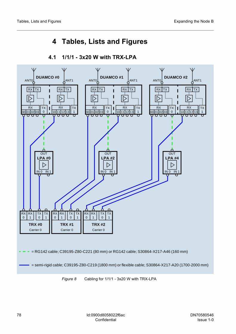
78 DN70580546Issue 1-0
Expanding the Node B
Id:0900d8058022f6acConfidential
Tables, Lists and Figures
4 Tables, Lists and Figures
4.1 1/1/1 - 3x20 W with TRX-LPA
Figure 8 Cabling for 1/1/1 - 3x20 W with TRX-LPA
= semi-rigid cable; C39195-Z80-C219 (1800 mm) or flexible cable; S30864-X217-A20 (1700-2000 mm)
RX 0
RX 1
TX 0
TX 1
TRX #0Carrier 0
RX 0
RX 1
TX 0
TX 1
TRX #1Carrier 0
RX 0
RX 1
TX 0
TX 1
TRX #2Carrier 0
IN 0
LPA #0
IN 1
OUT
IN 0
LPA #2
IN 1
OUT
IN 0
LPA #4
IN 1
OUT
= RG142 cable; C39195-Z80-C221 (80 mm) or RG142 cable; S30864-X217-A46 (160 mm)
RX TX
RX00 01 02 03
ANT0DUAMCO #0
TX0
RX TX
TX1
ANT1
RX
10 11 12 13
RX TX
RX00 01 02 03
ANT0DUAMCO #1
TX0
RX TX
TX1
ANT1
RX
10 11 12 13
RX TX
RX00 01 02 03
ANT0DUAMCO #2
TX0
RX TX
TX1
ANT1
RX
10 11 12 13
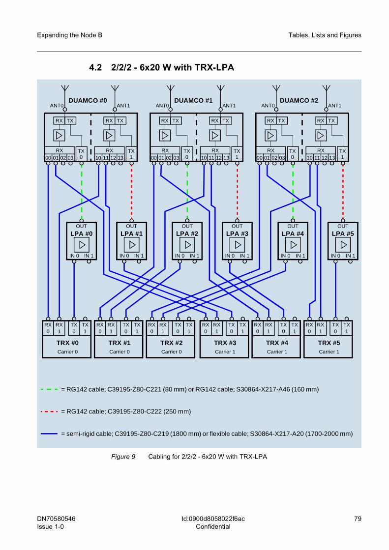
DN70580546 Issue 1-0
79
Expanding the Node B Tables, Lists and Figures
Id:0900d8058022f6acConfidential
4.2 2/2/2 - 6x20 W with TRX-LPA
Figure 9 Cabling for 2/2/2 - 6x20 W with TRX-LPA
= semi-rigid cable; C39195-Z80-C219 (1800 mm) or flexible cable; S30864-X217-A20 (1700-2000 mm)
RX 0
RX 1
TX 0
TX 1
TRX #0Carrier 0
RX 0
RX 1
TX 0
TX 1
TRX #1Carrier 0
RX 0
RX 1
TX 0
TX 1
TRX #2Carrier 0
RX 0
RX 1
TX 0
TX 1
TRX #3Carrier 1
RX 0
RX 1
TX 0
TX 1
TRX #4Carrier 1
RX 0
RX 1
TX 0
TX 1
TRX #5Carrier 1
IN 0
LPA #1
IN 1
OUT
IN 0
LPA #0
IN 1
OUT
IN 0
LPA #3
IN 1
OUT
IN 0
LPA #2
IN 1
OUT
IN 0
LPA #5
IN 1
OUT
IN 0
LPA #4
IN 1
OUT
= RG142 cable; C39195-Z80-C222 (250 mm)
RX TX
RX00 01 02 03
ANT0DUAMCO #0
TX0
RX TX
TX1
ANT1
RX10 11 12 13
RX TX
RX00 01 02 03
ANT0DUAMCO #1
TX0
RX TX
TX1
ANT1
RX10 11 12 13
RX TX
RX00 01 02 03
ANT0DUAMCO #2
TX0
RX TX
TX1
ANT1
RX10 11 12 13
= RG142 cable; C39195-Z80-C221 (80 mm) or RG142 cable; S30864-X217-A46 (160 mm)
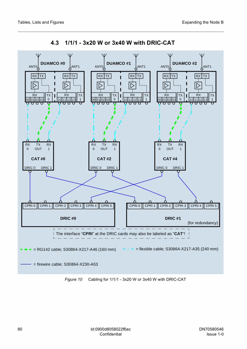
80 DN70580546Issue 1-0
Expanding the Node B
Id:0900d8058022f6acConfidential
Tables, Lists and Figures
4.3 1/1/1 - 3x20 W or 3x40 W with DRIC-CAT
Figure 10 Cabling for 1/1/1 - 3x20 W or 3x40 W with DRIC-CAT
CPRI 0
DRIC #0
DRIC 0
CAT #0
TX OUT
= RG142 cable; S30864-X217-A46 (160 mm)
RX TX
RX00 01 02 03
ANT0DUAMCO #0
TX0
RX TX
TX1
ANT1
RX
10 11 12 13
RX TX
RX00 01 02 03
ANT0DUAMCO #1
TX0
RX TX
TX1
ANT1
RX
10 11 12 13
RX TX
RX00 01 02 03
ANT0DUAMCO #2
TX0
RX TX
TX1
ANT1
RX
10 11 12 13
DRIC 1
RX 0
RX 1
CPRI 1 CPRI 2 CPRI 3 CPRI 4 CPRI 5
= flexible cable; S30864-X217-A35 (240 mm)
= firewire cable; S30864-X230-A53
DRIC 0
CAT #2
TX OUT
DRIC 1
RX 0
RX 1
DRIC 0
CAT #4
TX OUT
DRIC 1
RX 0
RX 1
CPRI 0
DRIC #1
CPRI 1 CPRI 2 CPRI 3 CPRI 4 CPRI 5
The interface “CPRI” at the DRIC cards may also be labeled as “CAT”!
(for redundancy)
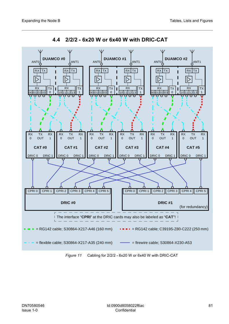
DN70580546 Issue 1-0
81
Expanding the Node B Tables, Lists and Figures
Id:0900d8058022f6acConfidential
4.4 2/2/2 - 6x20 W or 6x40 W with DRIC-CAT
Figure 11 Cabling for 2/2/2 - 6x20 W or 6x40 W with DRIC-CAT
CPRI 0
DRIC #0
DRIC 0
CAT #0
TX OUT
RX TX
RX00 01 02 03
ANT0DUAMCO #0
TX0
RX TX
TX1
ANT1
RX
10 11 12 13
RX TX
RX00 01 02 03
ANT0DUAMCO #1
TX0
RX TX
TX1
ANT1
RX
10 11 12 13
RX TX
RX00 01 02 03
ANT0DUAMCO #2
TX0
RX TX
TX1
ANT1
RX
10 11 12 13
DRIC 1
RX 0
RX 1
CPRI 1 CPRI 2 CPRI 3 CPRI 4 CPRI 5
DRIC 0
CAT #1
TX OUT
DRIC 1
RX 0
RX 1
DRIC 0
CAT #2
TX OUT
DRIC 1
RX 0
RX 1
DRIC 0
CAT #3
TX OUT
DRIC 1
RX 0
RX 1
DRIC 0
CAT #4
TX OUT
DRIC 1
RX 0
RX 1
DRIC 0
CAT #5
TX OUT
DRIC 1
RX 0
RX 1
CPRI 0
DRIC #1
CPRI 1 CPRI 2 CPRI 3 CPRI 4 CPRI 5
= RG142 cable; S30864-X217-A46 (160 mm)
= flexible cable; S30864-X217-A35 (240 mm) = firewire cable; S30864-X230-A53
= RG142 cable; C39195-Z80-C222 (250 mm)
The interface “CPRI” at the DRIC cards may also be labeled as “CAT”!
(for redundancy)
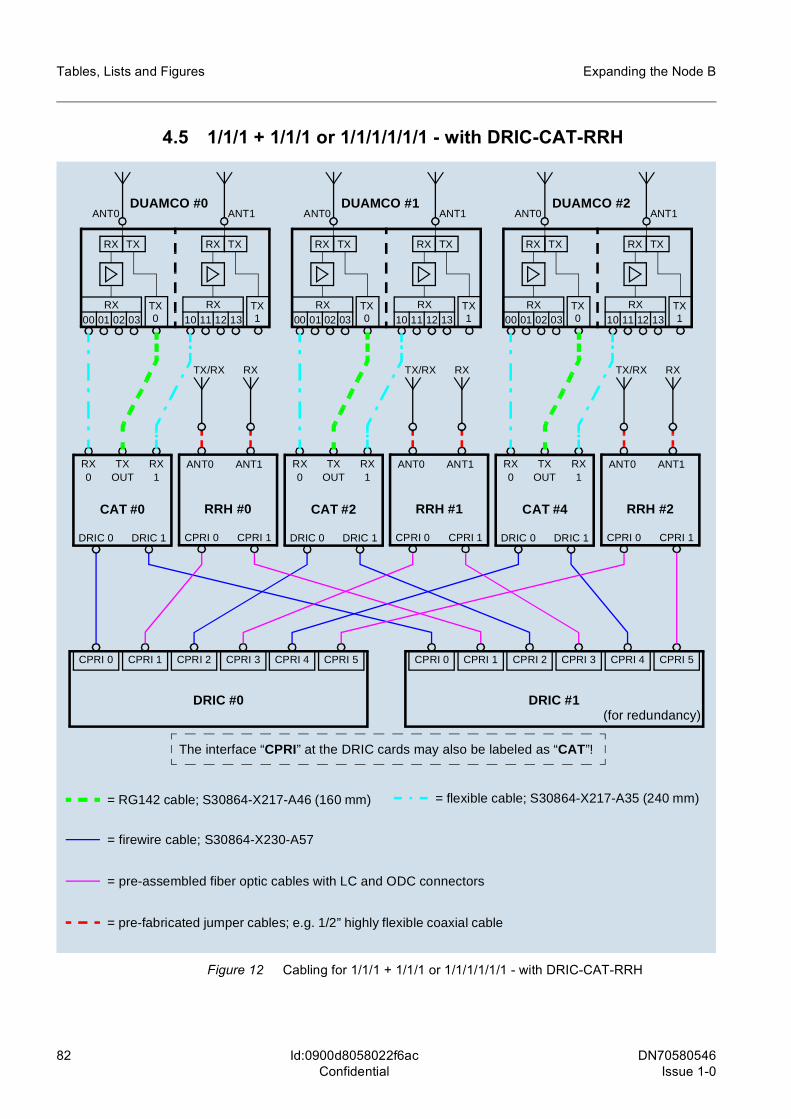
82 DN70580546Issue 1-0
Expanding the Node B
Id:0900d8058022f6acConfidential
Tables, Lists and Figures
4.5 1/1/1 + 1/1/1 or 1/1/1/1/1/1 - with DRIC-CAT-RRH
Figure 12 Cabling for 1/1/1 + 1/1/1 or 1/1/1/1/1/1 - with DRIC-CAT-RRH
CPRI 0
DRIC #0
DRIC 0
CAT #0
TX OUT
= RG142 cable; S30864-X217-A46 (160 mm)
RX TX
RX00 01 02 03
ANT0DUAMCO #0
TX0
RX TX
TX1
ANT1
RX
10 11 12 13
RX TX
RX00 01 02 03
ANT0DUAMCO #1
TX0
RX TX
TX1
ANT1
RX
10 11 12 13
RX TX
RX00 01 02 03
ANT0DUAMCO #2
TX0
RX TX
TX1
ANT1
RX
10 11 12 13
DRIC 1
RX 0
RX 1
CPRI 1 CPRI 2 CPRI 3 CPRI 4 CPRI 5
= flexible cable; S30864-X217-A35 (240 mm)
= firewire cable; S30864-X230-A57
DRIC 0
CAT #2
TX OUT
DRIC 1
RX 0
RX 1
DRIC 0
CAT #4
TX OUT
DRIC 1
RX 0
RX 1
CPRI 0
DRIC #1
CPRI 1 CPRI 2 CPRI 3 CPRI 4 CPRI 5
The interface “CPRI” at the DRIC cards may also be labeled as “CAT”!
CPRI 0
RRH #0
ANT0
CPRI 1
ANT1
TX/RX RX
CPRI 0
RRH #1
ANT0
CPRI 1
ANT1
TX/RX RX
CPRI 0
RRH #2
ANT0
CPRI 1
ANT1
TX/RX RX
= pre-assembled fiber optic cables with LC and ODC connectors
= pre-fabricated jumper cables; e.g. 1/2” highly flexible coaxial cable
(for redundancy)
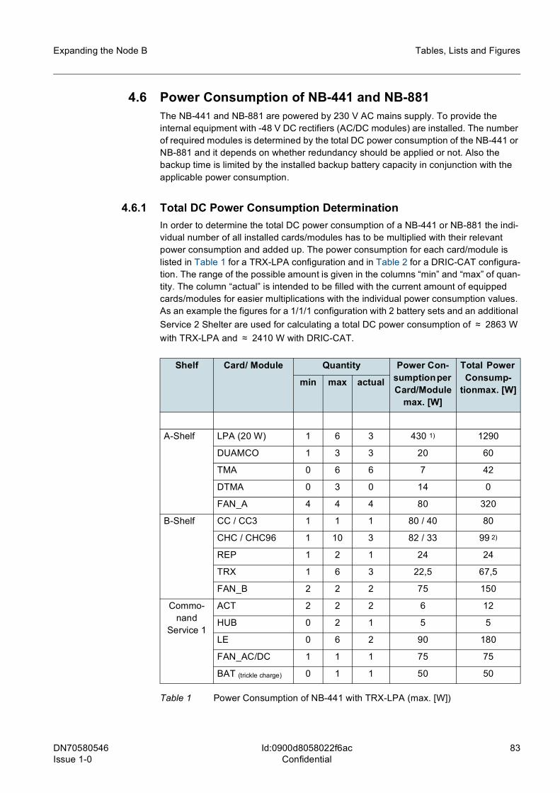
DN70580546 Issue 1-0
83
Expanding the Node B Tables, Lists and Figures
Id:0900d8058022f6acConfidential
4.6 Power Consumption of NB-441 and NB-881The NB-441 and NB-881 are powered by 230 V AC mains supply. To provide the internal equipment with -48 V DC rectifiers (AC/DC modules) are installed. The number of required modules is determined by the total DC power consumption of the NB-441 or NB-881 and it depends on whether redundancy should be applied or not. Also the backup time is limited by the installed backup battery capacity in conjunction with the applicable power consumption.
4.6.1 Total DC Power Consumption DeterminationIn order to determine the total DC power consumption of a NB-441 or NB-881 the indi-vidual number of all installed cards/modules has to be multiplied with their relevant power consumption and added up. The power consumption for each card/module is listed in Table 1 for a TRX-LPA configuration and in Table 2 for a DRIC-CAT configura-tion. The range of the possible amount is given in the columns “min” and “max” of quan-tity. The column “actual” is intended to be filled with the current amount of equipped cards/modules for easier multiplications with the individual power consumption values. As an example the figures for a 1/1/1 configuration with 2 battery sets and an additional Service 2 Shelter are used for calculating a total DC power consumption of ≈ 2863 W with TRX-LPA and ≈ 2410 W with DRIC-CAT.
Shelf Card/ Module Quantity Power Con-sumption per Card/Module
max. [W]
Total Power Consump-
tionmax. [W]min max actual
A-Shelf LPA (20 W) 1 6 3 430 1) 1290
DUAMCO 1 3 3 20 60
TMA 0 6 6 7 42
DTMA 0 3 0 14 0
FAN_A 4 4 4 80 320
B-Shelf CC / CC3 1 1 1 80 / 40 80
CHC / CHC96 1 10 3 82 / 33 99 2)
REP 1 2 1 24 24
TRX 1 6 3 22,5 67,5
FAN_B 2 2 2 75 150
Commo-nand
Service 1
ACT 2 2 2 6 12
HUB 0 2 1 5 5
LE 0 6 2 90 180
FAN_AC/DC 1 1 1 75 75
BAT (trickle charge) 0 1 1 50 50
Table 1 Power Consumption of NB-441 with TRX-LPA (max. [W])
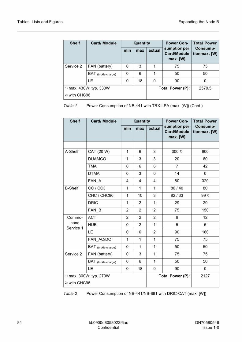
84 DN70580546Issue 1-0
Expanding the Node B
Id:0900d8058022f6acConfidential
Tables, Lists and Figures
Service 2 FAN (battery) 0 3 1 75 75
BAT (trickle charge) 0 6 1 50 50
LE 0 18 0 90 0
1) max. 430W; typ. 330W2) with CHC96
Total Power (P): 2579,5
Shelf Card/ Module Quantity Power Con-sumption per Card/Module
max. [W]
Total Power Consump-
tionmax. [W]min max actual
A-Shelf CAT (20 W) 1 6 3 300 1) 900
DUAMCO 1 3 3 20 60
TMA 0 6 6 7 42
DTMA 0 3 0 14 0
FAN_A 4 4 4 80 320
B-Shelf CC / CC3 1 1 1 80 / 40 80
CHC / CHC96 1 10 3 82 / 33 99 2)
DRIC 1 2 1 29 29
FAN_B 2 2 2 75 150
Commo-nand
Service 1
ACT 2 2 2 6 12
HUB 0 2 1 5 5
LE 0 6 2 90 180
FAN_AC/DC 1 1 1 75 75
BAT (trickle charge) 0 1 1 50 50
Service 2 FAN (battery) 0 3 1 75 75
BAT (trickle charge) 0 6 1 50 50
LE 0 18 0 90 0
1) max. 300W; typ. 270W2) with CHC96
Total Power (P): 2127
Table 2 Power Consumption of NB-441/NB-881 with DRIC-CAT (max. [W])
Shelf Card/ Module Quantity Power Con-sumption per Card/Module
max. [W]
Total Power Consump-
tionmax. [W]min max actual
Table 1 Power Consumption of NB-441 with TRX-LPA (max. [W]) (Cont.)
DN70580546 Issue 1-0
85
Expanding the Node B Tables, Lists and Figures
Id:0900d8058022f6acConfidential
4.6.2 Required Number of AC/DC ModulesEach AC/DC module is able to supply 1600 W. The frame AD/DC is capable to contain 6 AC/DC modules. Considering the N + 1 redundancy concept (load sharing) a total DC power of 8000W (5 x 1600 W) can be achieved.
With the total DC power consumption (P) determined according to the table above (Table 1) it is easy to evaluate the necessary quantity (X) of AC/DC modules by means of the following formulas:
X Int P W[ ]1600W-------------------⎝ ⎠
⎛ ⎞ 1+= without redundancy
1 < X < 5
X Int P W[ ]1600W-------------------⎝ ⎠
⎛ ⎞ 2+= with redundancy
2 < X < 6
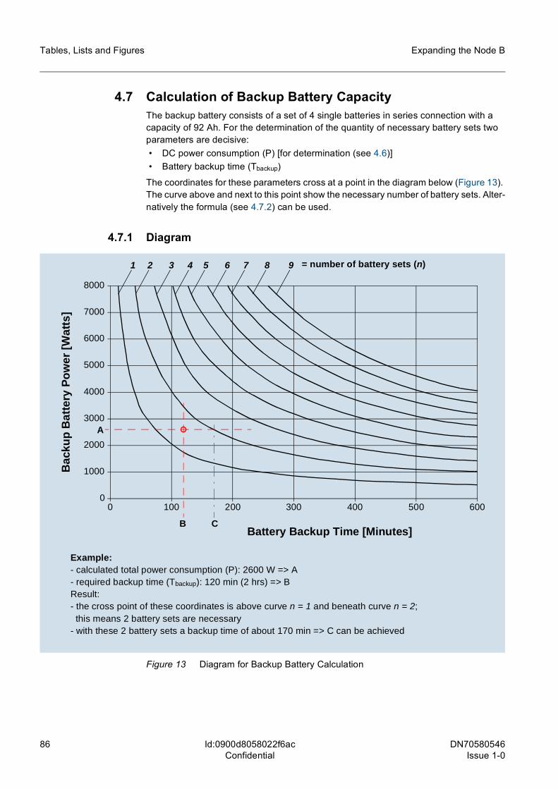
86 DN70580546Issue 1-0
Expanding the Node B
Id:0900d8058022f6acConfidential
Tables, Lists and Figures
4.7 Calculation of Backup Battery CapacityThe backup battery consists of a set of 4 single batteries in series connection with a capacity of 92 Ah. For the determination of the quantity of necessary battery sets two parameters are decisive: • DC power consumption (P) [for determination (see 4.6)] • Battery backup time (Tbackup)
The coordinates for these parameters cross at a point in the diagram below (Figure 13). The curve above and next to this point show the necessary number of battery sets. Alter-natively the formula (see 4.7.2) can be used.
4.7.1 Diagram
Figure 13 Diagram for Backup Battery Calculation
8000
7000
6000
5000
4000
3000
2000
1000
0100 200 300 400 500 6000
1 2 3 4 5 6 7 8 9
Battery Backup Time [Minutes]
Bac
kup
Bat
tery
Po
wer
[W
atts
]
= number of battery sets (n)
A
B
Example:- calculated total power consumption (P): 2600 W => A- required backup time (Tbackup): 120 min (2 hrs) => BResult:- the cross point of these coordinates is above curve n = 1 and beneath curve n = 2;
this means 2 battery sets are necessary- with these 2 battery sets a backup time of about 170 min => C can be achieved
C
DN70580546 Issue 1-0
87
Expanding the Node B Tables, Lists and Figures
Id:0900d8058022f6acConfidential
4.7.2 FormulaThe curves in Figure 12 can be approximated with the following formula:
This formula can be transformed which gives the achievable backup time at a given power consumption and the number of battery sets:
For the evaluation of the necessary battery sets at a given power consumption and the required backup time the following formula applies:
Using the values of the example in the diagram the result will be: n = Int (1,5) + 1 = 2
P W[ ] n 92000⋅Tbackup
α min[ ]----------------------------------- with α 0 83,==
Tbackup min[ ] n 92000⋅P W[ ]
---------------------------⎝ ⎠⎛ ⎞
1α---
with α 0 83,==
n IntP W[ ] Tbackup
α min[ ]⋅92000
---------------------------------------------------------⎝ ⎠⎜ ⎟⎛ ⎞
1 with α 0 83,=+=