ce 316 design of concrete structures sessional (lab manual) · pdf filedesign of concrete...
TRANSCRIPT

CE 316 Design of Concrete Structures Sessional
Department of Civil Engineering Ahsanullah University of Science and Technology
Version 2, November, 2017

Preface
Design of Concrete Structure Sessional-I (CE316) manual contains the analysis and design of
Slab bridge, Deck Girder Bridge and a Low rise masonry building. This sessional is focused on
bridge design and building design with an intention to make the students familiar with the
difference between the design approach of these two very basic type of structures. For providing
a complete guideline about the design procedure of a low rise masonry building, detailed
procedures are given on the design of slab, beam, stair and foundation. Also, different types of
live load which are considered during the design of concrete structures are emphasized in this
manual. AASHTO Code, Bangladesh National Building Code (BNBC 2006) and ACI Building
Code are followed in this manual.
Sincere gratitude and reverences to the most respected faculty members Prof. Dr. Md.
Mahmudur Rahman, Prof. Dr. Abdur Rouf and Mr. Md. Mashfiqul Islam for their precious time,
valuable suggestions, and constructive advice in the entire process of updating the manual.
Fatema Tuz Zahura
Sabreena Nasrin
Department of Civil Engineering
Ahsanullah University of Science and Technology
Updated by
Fatema Tuz Zahura
Sabuj Chowdhury
Department of Civil Engineering
Ahsanullah University of Science and Technology
Index
Course Content
Page
Design of Low Rise
Masonry Structure
1. Design of slab 1-17
2. Design of Beam 18-26
3. Design of Stair 27-31
4. Design of Sunshade 32-33
5. Design of Lintel 34-36
6. Design of Foundation
37-41
Design of Slab Bridge 1. Design of Slab 42-43
2. Design of Curb
44-46
Design of Deck Girder Bridge 1.Design of Slab 47-51
2. Design of Interior Girder 52-53
3. Design of Exterior Girder 54-55
4. Diaphragms
56
References 57

Design of Low Rise Masonry Building
Introduction
Load bearing construction is most appropriately used for buildings in which the floor area is
subdivided into a relatively large number of rooms of small to medium size and in which the floor
plan is repeated on each story throughout the height of the building. These considerations give
ample opportunity for disposing load bearing walls, which are continuous from foundation to roof
level and, because of the moderate floor spans, are not called upon to carry unduly heavy
concentrations of vertical load. The types of buildings which are compatible with these
requirements include flats, hostels, hotels and other residential buildings.
The basic advantage of masonry construction is that it is possible to use the same element to
perform a variety of functions, which in a steel framed building, for example, have to be provided
for separately, with consequent complication in detailed construction. Thus masonry may,
simultaneously, provide structure, subdivision of space, thermal and acoustic insulation as well as
fire and weather protection. As a material, it is relatively cheap but durable and produces external
wall finishes of very acceptable appearance. Masonry construction is flexible in terms of building
layout and can be constructed without very large capital expenditure on the part of the builder.
However, the quality of the masonry in a building depends on the materials used, and hence all
masonry materials must conform to certain minimum standards. The basic components of masonry
are block, brick and mortar, the latter being in itself a composite of cement, lime and sand and
sometimes of other constituents.

Page | 2
1. Design of one way slab (USD)
One-way slabs are those slabs having supports along one way only (Figure 1(a)) or slabs having
supports having on all sides but with an aspect ratio in plan of 2:1 or greater, in which bending is
primarily about the long axis (Figure 2(a)). The slabs having supports on all sides acts as two way
slab (Figure 1(b) and 2(b)) where there are bending about the both axes, but acts as one way slab
where L/B ≥ 2.
One way slab can be
1. Solid
2. Hollow or
3. Ribbed
(a) One-way slab (b) Two-way slab
Figure 1: One-way Slab and Two-way Slab
In figure 2(a) slab is supported on two opposite sides only. In this case the structural action of the
slab is essentially one way.
In figure 2(b) there are beams on all four sides. Now if length to width ratio is 2 or greater, slab
acts as one way slab even though supports are provided on all sides.
LOADING OF ONE WAY SLAB
Figure 2: Slab (a) Supported on two opposite sides only and (b) Supported on all four sides

Page | 3
Figure 2(a) shows that when slabs are supported on two opposite sides only loads being carried by
the slab in the direction perpendicular to the supporting beams.
Figure 2(b) shows that when supports are provided on all sides most of the load is carried in the
short direction to the supporting beams and one way action is obtained.
1.1 SPECIFICATIONS
Minimum Slab Thickness
To control deflection, ACI Code 9.5.2.1 specifies minimum thickness values for one-way solid
slabs.
Element Simply
Supported
One end
continuous
Both ends
continuous Cantilever
One-way solid
slabs l/20 l/24 l/28 l/10
Here, l is the clear span
Multiplying factor = 0.4 +𝑓𝑦
100 , 𝑓𝑦 in ksi
If,
Thickness < 6 inch then upper rounding to neatest 0.25
Thickness ≥ 6 inch then upper rounding to neatest 0.50
Minimum Concrete Cover
According to ACI Code 7.7.1, the following minimum concrete cover is to be provided:
a. Concrete not exposed to weather or in contact with ground:
• Larger than Ø 36 mm bar ------------------------------------------------------------- 4 cm
• Ø 36 mm and smaller bars ------------------------------------------------------------- 2 cm
b. Concrete exposed to weather or in contact with ground:
• Ø 19 mm and larger bars---------------------------------------------------------------- 5 cm
• Ø 16 mm and smaller bars -------------------------------------------------------------- 4 cm
c. Concrete cast against and permanently exposed to earth ---------------------------------- 7.5 cm
Span Length
According to ACI code 8.7.1, if the slab rests freely on its supports, the span length may be taken
equal to the clear span plus the depth of the slab but need not exceed the distance between centers
of supports.
Page | 4
Bar Spacing
The spacing of the flexural bars should not exceed 3 times the thickness h or 18 inch according to
ACI code 7.6.5.
The spacing of temperature and shrinkage reinforcement should not be placed farther apart than 5
times the slab thickness or 18 inch according to ACI code 7.12.2.
Generally, bar size should be selected so that actual spacing is not less than about 1.5 times the
slab thickness.
Maximum Reinforcement Ratio
Reinforcement ratio: Reinforcement ratio is the ratio of reinforcement area to gross concrete area.
One-way solid slabs are designed as rectangular sections subjected to moment. Thus, the
maximum reinforcement ratio corresponds to a net tensile stain in the reinforcement,(𝜖𝑡) of 0.004.
For temperature and shrinkage reinforcement ratio:
According to ACI Code 7.12.2.1
Slabs with Grade 40 or 50 deformed bars…………………………………………… 0.0020
Slabs with Grade 60 deformed bars ………………………………………………… 0.0018
Slabs where reinforcement with yield strength
Exceeding 60000 psi..…………………………………………………………… 0.0018×60000
𝑓𝑦
For flexural reinforcement:
According to ACI Code 10.5.4,
The minimum flexural reinforcement ratio is not to be less than the shrinkage reinforcement.
Page | 5
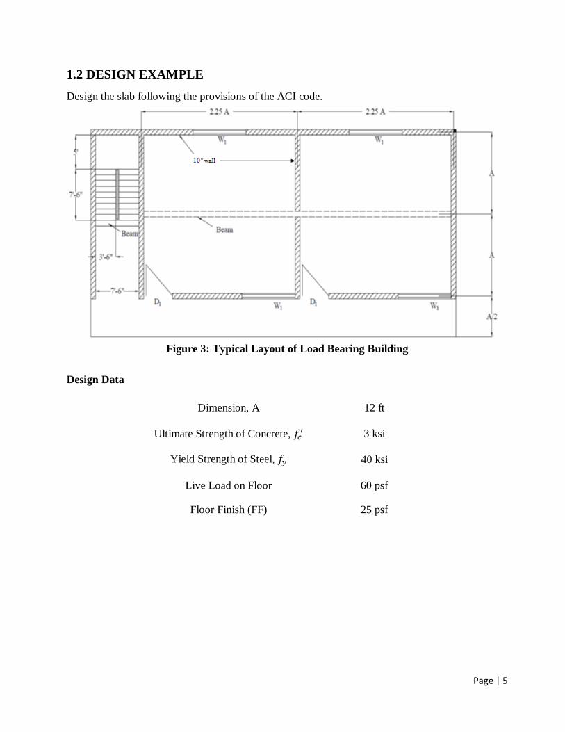
1.2 DESIGN EXAMPLE
Design the slab following the provisions of the ACI code.
Figure 3: Typical Layout of Load Bearing Building
Design Data
Dimension, A 12 ft
Ultimate Strength of Concrete, 𝑓𝑐′ 3 ksi
Yield Strength of Steel, 𝑓𝑦 40 ksi
Live Load on Floor 60 psf
Floor Finish (FF) 25 psf

Page | 6
THICKNESS ESTIMATION
Figure 4: Load Transfer in Shorter Direction
Figure 5: Section 1-1
For one end continuous
𝑙 = 12 × 12 −10
2−
12
2= 133″
Multiplying factor, MF = 0.4 +40
100= 0.8
Thickness =𝑙
24× 0.8 = 4.43″
For both end continuous
𝑙 = 12 × 12 −10
2−
12
2= 133″
Multiplying factor, MF = 0.4 +40
100= 0.8
Thickness =𝑙
28× 0.8 = 3.80″

Page | 7
For Cantilever
𝑙 = 6 × 12 −10
2= 67″
Multiplying factor, MF = 0.4 +40
100= 0.8
Thickness =𝑙
10× 0.8 = 5.36″
Among the thickness maximum thickness = 5.36″ Hence use 5.5″
DETERMINING LOADS
• Consider only a 1 ft width of beam.
• Floor Finish = 25 psf
• Live load = 60 psf
• Dead load = 150×5.50/12=68.75 psf (Unit wt. of Concrete = 150 pcf)
• Factored DL and LL, wu =[(68.75+25)x1.2+60 x1.6] psf
= 208.5 psf
= 0.21 ksf
DETERMINING MAXIMUM MOMENTS
Moment coefficients at critical sections by ACI code:
Figure 6: Moment Coefficient

Page | 8
• At Section 1 : 𝑀𝑢 = −0 × 𝑤𝑢𝑙2 = −0 𝑘 − 𝑓𝑡/𝑓𝑡 = −0 𝑘 − 𝑖𝑛/𝑓𝑡
• At Section 2 : 𝑀𝑢 =1
11× 𝑤𝑢𝑙2 = 2.35 𝑘 − 𝑓𝑡/𝑓𝑡 = 28.2 𝑘 − 𝑖𝑛/𝑓𝑡
• At Section 3 (Left) :𝑀𝑢 = −1
12× 𝑤𝑢𝑙2 = −2.15 𝑘 − 𝑓𝑡/𝑓𝑡 = −25.8 𝑘 − 𝑖𝑛/𝑓𝑡
At Section 3 (Right) : 𝑀𝑢 = −1
12× 𝑤𝑢𝑙2 = −2.15 𝑘 − 𝑓𝑡/𝑓𝑡 = −25.8 𝑘 − 𝑖𝑛/𝑓𝑡
At Section 3 (Max.) : 𝑀𝑢 = −25.8 𝑘 − 𝑖𝑛/𝑓𝑡
• At Section 4 : 𝑀𝑢 =1
11× 𝑤𝑢𝑙2 = 2.35 𝑘 − 𝑓𝑡/𝑓𝑡 = 28.2 𝑘 − 𝑖𝑛/𝑓𝑡
• At Section 5 (Left) : 𝑀𝑢 = −1
11× 𝑤𝑢𝑙2 = −2.35 𝑘 − 𝑓𝑡/𝑓𝑡 = −28.2 𝑘 − 𝑖𝑛/𝑓𝑡
At Section 5 (Right) : 𝑀𝑢 = −12
× 𝑤𝑢𝑙2 = −3.27 𝑘 − 𝑓𝑡/𝑓𝑡 = −39.27 𝑘 − 𝑖𝑛/𝑓𝑡
At Section 5 (Max.) : 𝑀𝑢 = −39.27 𝑘 − 𝑖𝑛/𝑓𝑡
Maximum Moment (Only Value) : 𝑀𝑚𝑎𝑥 = 39.27 𝑘 − 𝑖𝑛/𝑓𝑡 (For all Sections)
MINIMUM EFFECTIVE DEPTH
𝜌 = 0.85𝛽1
𝑓𝑐′
𝑓𝑦
𝜖𝑢
𝜖𝑢 + 𝜖𝑡
𝜌 = 𝜌0.005 = 0.85𝛽1
𝑓𝑐′
𝑓𝑦
𝜖𝑢
𝜖𝑢 + 0.005
𝜌 = 𝜌0.005 = 0.85 × 0.85 ×3
40×
0.003
0.003 + 0.005= 0.0203
𝑑𝑟𝑒𝑞 =√
𝑀𝑚𝑎𝑥
∅𝜌𝑓𝑦𝑏 (1 − 0.59𝜌𝑓𝑦
𝑓𝑐′ )
= √39.27
0.9 × 0.0203 × 40 × 12 × (1 − 0.59 × 0.0203 ×40
3)
= 2.31 𝑖𝑛

Page | 9
CHECKING AVAILABILITY OF THICKNESS
As required effective depth, dreq is less than provided effective depth, dprov. of (5.50-1.00) = 4.50 in,
the thickness of 5.50 in can be adopted.
MINIMUM REINFORCEMENT AREA
𝐴𝑠,𝑚𝑖𝑛 = 0.002 𝑏𝑡 = (0.002 × 12 × 5.5) 𝑖𝑛2/𝑓𝑡
= 0.13 𝑖𝑛2/𝑓𝑡
Minimum reinforcement of 0.13 in2/ft should be provided at every section.
REINFORCEMENT AREA DETERMINATION AT ALL SECTIONS
𝐴𝑠 =𝑀𝑢
∅𝑓𝑦(𝑑 − 𝑎/2)& 𝑎 =
𝐴𝑠𝑓𝑦
0.85𝑓𝑐′𝑏
At Section 1: (Mu = 0 k-in/ft)
Let,
𝑎 = 1 in
𝐴𝑠 =𝑀𝑢
∅𝑓𝑦(𝑑 − 𝑎/2)
=0
0.9 × 40(4.5 − 1/2)
= 0 𝑖𝑛2/𝑓𝑡
𝑎𝑛𝑑,
𝑎 =𝐴𝑠𝑓𝑦
0.85𝑓𝑐′𝑏
𝑎 =0 × 40
0.85 × 3 × 12
= 0 𝑖𝑛
Again,
𝐴𝑠 =𝑀𝑢
∅𝑓𝑦(𝑑 − 𝑎/2)
=0
0.9 × 40(4.5 − 0/2)
= 0 𝑖𝑛2/𝑓𝑡 (Same as before)(But As < As,min)
= 0.013 𝑖𝑛2/𝑓𝑡
Page | 10
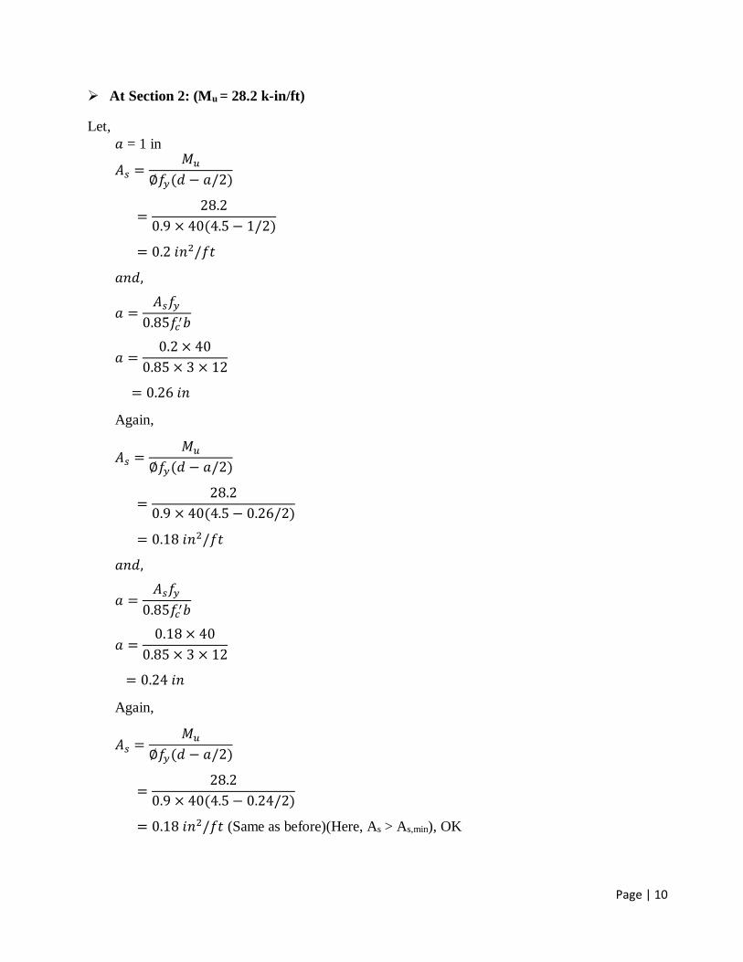
At Section 2: (Mu = 28.2 k-in/ft)
Let,
𝑎 = 1 in
𝐴𝑠 =𝑀𝑢
∅𝑓𝑦(𝑑 − 𝑎/2)
=28.2
0.9 × 40(4.5 − 1/2)
= 0.2 𝑖𝑛2/𝑓𝑡
𝑎𝑛𝑑,
𝑎 =𝐴𝑠𝑓𝑦
0.85𝑓𝑐′𝑏
𝑎 =0.2 × 40
0.85 × 3 × 12
= 0.26 𝑖𝑛
Again,
𝐴𝑠 =𝑀𝑢
∅𝑓𝑦(𝑑 − 𝑎/2)
=28.2
0.9 × 40(4.5 − 0.26/2)
= 0.18 𝑖𝑛2/𝑓𝑡
𝑎𝑛𝑑,
𝑎 =𝐴𝑠𝑓𝑦
0.85𝑓𝑐′𝑏
𝑎 =0.18 × 40
0.85 × 3 × 12
= 0.24 𝑖𝑛
Again,
𝐴𝑠 =𝑀𝑢
∅𝑓𝑦(𝑑 − 𝑎/2)
=28.2
0.9 × 40(4.5 − 0.24/2)
= 0.18 𝑖𝑛2/𝑓𝑡 (Same as before)(Here, As > As,min), OK

Page | 11
At Section 3: (Mu = 25.8 k-in/ft)
Let,
𝑎 = 1 in
𝐴𝑠 =𝑀𝑢
∅𝑓𝑦(𝑑 − 𝑎/2)
=25.8
0.9 × 40(4.5 − 1/2)
= 0.18 𝑖𝑛2/𝑓𝑡
𝑎𝑛𝑑,
𝑎 =𝐴𝑠𝑓𝑦
0.85𝑓𝑐′𝑏
𝑎 =0.18 × 40
0.85 × 3 × 12
= 0.24 𝑖𝑛
Again,
𝐴𝑠 =𝑀𝑢
∅𝑓𝑦(𝑑 − 𝑎/2)
=25.8
0.9 × 40(4.5 − 0.24/2)
= 0.16 𝑖𝑛2/𝑓𝑡
𝑎𝑛𝑑,
𝑎 =𝐴𝑠𝑓𝑦
0.85𝑓𝑐′𝑏
𝑎 =0.16 × 40
0.85 × 3 × 12
= 0.21 𝑖𝑛
Again,
𝐴𝑠 =𝑀𝑢
∅𝑓𝑦(𝑑 − 𝑎/2)
=25.8
0.9 × 40(4.5 − 0.21/2)
= 0.16 𝑖𝑛2/𝑓𝑡 (Same as before)(Here, As > As,min), OK

Page | 12
At Section 4: (Mu = 28.2 k-in/ft)
Let,
𝑎 = 1 in
𝐴𝑠 =𝑀𝑢
∅𝑓𝑦(𝑑 − 𝑎/2)
=28.2
0.9 × 40(4.5 − 1/2)
= 0.2 𝑖𝑛2/𝑓𝑡
𝑎𝑛𝑑,
𝑎 =𝐴𝑠𝑓𝑦
0.85𝑓𝑐′𝑏
𝑎 =0.2 × 40
0.85 × 3 × 12
= 0.26 𝑖𝑛
Again,
𝐴𝑠 =𝑀𝑢
∅𝑓𝑦(𝑑 − 𝑎/2)
=28.2
0.9 × 40(4.5 − 0.26/2)
= 0.18 𝑖𝑛2/𝑓𝑡
𝑎𝑛𝑑,
𝑎 =𝐴𝑠𝑓𝑦
0.85𝑓𝑐′𝑏
𝑎 =0.18 × 40
0.85 × 3 × 12
= 0.24 𝑖𝑛
Again,
𝐴𝑠 =𝑀𝑢
∅𝑓𝑦(𝑑 − 𝑎/2)
=28.2
0.9 × 40(4.5 − 0.24/2)
= 0.18 𝑖𝑛2/𝑓𝑡 (Same as before)(Here, As > As,min), OK

Page | 13
At Section 5: (Mu = 39.27 k-in/ft)
Let,
𝑎 = 1 in
𝐴𝑠 =𝑀𝑢
∅𝑓𝑦(𝑑 − 𝑎/2)
=39.27
0.9 × 40(4.5 − 1/2)
= 0.27 𝑖𝑛2/𝑓𝑡
𝑎𝑛𝑑,
𝑎 =𝐴𝑠𝑓𝑦
0.85𝑓𝑐′𝑏
𝑎 =0.27 × 40
0.85 × 3 × 12
= 0.35 𝑖𝑛
Again,
𝐴𝑠 =𝑀𝑢
∅𝑓𝑦(𝑑 − 𝑎/2)
=39.27
0.9 × 40(4.5 − 0.35/2)
= 0.25 𝑖𝑛2/𝑓𝑡
𝑎𝑛𝑑,
𝑎 =𝐴𝑠𝑓𝑦
0.85𝑓𝑐′𝑏
𝑎 =0.25 × 40
0.85 × 3 × 12
= 0.33 𝑖𝑛
Again,
𝐴𝑠 =𝑀𝑢
∅𝑓𝑦(𝑑 − 𝑎/2)
=39.27
0.9 × 40(4.5 − 0.33/2)
= 0.25 𝑖𝑛2/𝑓𝑡 (Same as before)(Here, As > As,min), OK

Page | 14
Figure 7: Reinforcement Area Required
REINFORCEMENT SPACING DETERMINATION
Short Direction:
𝑆𝑚𝑖𝑛 = 1.5𝑡 = 1.5 × 5.5 = 8.25"
𝑆𝑚𝑎𝑥 = 3𝑡 𝑜𝑟 18=(3×5.5)" 𝑜𝑟 18" =16.5" 𝑜𝑟 18" = 16.5" (𝐿𝑜𝑤𝑒𝑟 𝑜𝑛𝑒)
𝑨𝒔 = 𝟎. 𝟏𝟖 𝒊𝒏𝟐/𝒇𝒕 ∶ (If #3 is provided) (At Section 2 & Section 4)
0.18 in2 reinforcement required in 12 inch
1 in2 reinforcement required in 12
0.18inch
0.11 in2 reinforcement required in 12×0.11
0.18inch
= 7.33" ≈ 7" (0.5" 𝑙𝑜𝑤𝑒𝑟 𝑟𝑜𝑢𝑛𝑑𝑖𝑛𝑔)
But, 𝑆 < 𝑆𝑚𝑖𝑛 (not Ok)
𝑨𝒔 = 𝟎. 𝟏𝟖 𝒊𝒏𝟐/𝒇𝒕 ∶ (If #4 is provided) (At Section 2 & Section 4)
0.18 in2 reinforcement required in 12 inch
1 in2 reinforcement required in 12
0.18inch
0.2 in2 reinforcement required in 12×0.2
0.18inch
= 13.33" ≈ 13" (0.5" 𝑙𝑜𝑤𝑒𝑟 𝑟𝑜𝑢𝑛𝑑𝑖𝑛𝑔)
Now, 𝑆𝑚𝑖𝑛 < 𝑆 < 𝑆𝑚𝑎𝑥 (Ok)
∴ #𝟒 @𝟏𝟑" 𝒄/𝒄 𝒂𝒍𝒕. 𝒄𝒌𝒅
𝑨𝒔 = 𝟎. 𝟏𝟑 𝒊𝒏𝟐/𝒇𝒕 ∶ (At Section 1)
#4 @ 26" 𝑐/𝑐 𝑖𝑠 𝑎𝑙𝑟𝑒𝑎𝑑𝑦 𝑝𝑟𝑜𝑣𝑖𝑑𝑒𝑑
In 26 inch already provided reinforcement area = 0.2 in2

Page | 15
In 12 inch required reinforcement area = 0.13 in2
In 1 inch required reinforcement area = 0.13×26
12 in2
In 26 inch required reinforcement area = 0.28 in2
Extra reinforcement required = (0.28-0.2) =0.08 in2
No. of extra top bar required (if # 3 bar is used) = 0.08
0.11= 0.73≈ 1
𝟏#𝟑 𝒆𝒙𝒕𝒓𝒂 𝒕𝒐𝒑 𝒃𝒆𝒕𝒘𝒆𝒆𝒏 𝒄𝒌𝒅. 𝒃𝒂𝒓
𝑨𝒔 = 𝟎. 𝟏𝟔 𝒊𝒏𝟐/𝒇𝒕 ∶ (At Section 3)
#4 @ 26" 𝑐/𝑐 𝑖𝑠 𝑎𝑙𝑟𝑒𝑎𝑑𝑦 𝑝𝑟𝑜𝑣𝑖𝑑𝑒𝑑
In 26 inch already provided reinforcement area = 0.2 in2
In 12 inch required reinforcement area = 0.16 in2
In 1 inch required reinforcement area = 0.16×26
12 in2
In 26 inch required reinforcement area = 0.35 in2
Extra reinforcement required = (0.35-0.2) =0.15 in2
No. of extra top bar required (if # 4 bar is used) = 0.15
0.2= 0.75≈ 1
𝟏#𝟒 𝒆𝒙𝒕𝒓𝒂 𝒕𝒐𝒑 𝒃𝒆𝒕𝒘𝒆𝒆𝒏 𝒄𝒌𝒅. 𝒃𝒂𝒓
𝑨𝒔 = 𝟎. 𝟐𝟓 𝒊𝒏𝟐/𝒇𝒕 ∶ (At Section 5)
#4 @ 26" 𝑐/𝑐 𝑖𝑠 𝑎𝑙𝑟𝑒𝑎𝑑𝑦 𝑝𝑟𝑜𝑣𝑖𝑑𝑒𝑑
In 26 inch already provided reinforcement area = 0.2 in2
In 12 inch required reinforcement area = 0.25 in2
In 1 inch required reinforcement area = 0.25×26
12 in2
In 26 inch required reinforcement area = 0.54 in2
Extra reinforcement required = (0.54-0.2) =0.34 in2
No. of extra top bar required (if # 4 bar is used) = 0.34
0.2= 1.70≈2
𝟐#𝟒 𝒆𝒙𝒕𝒓𝒂 𝒕𝒐𝒑 𝒃𝒆𝒕𝒘𝒆𝒆𝒏 𝒄𝒌𝒅. 𝒃𝒂𝒓
Page | 16
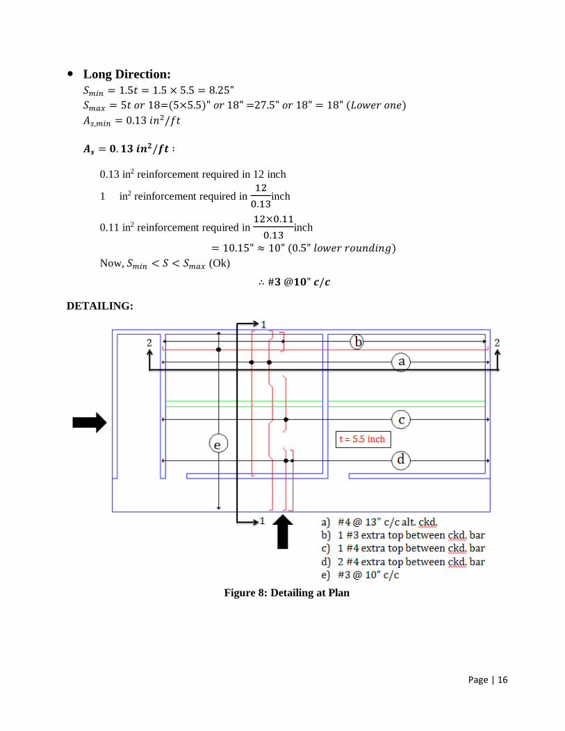
Long Direction:
𝑆𝑚𝑖𝑛 = 1.5𝑡 = 1.5 × 5.5 = 8.25"
𝑆𝑚𝑎𝑥 = 5𝑡 𝑜𝑟 18=(5×5.5)" 𝑜𝑟 18" =27.5" 𝑜𝑟 18" = 18" (𝐿𝑜𝑤𝑒𝑟 𝑜𝑛𝑒)
𝐴𝑠,𝑚𝑖𝑛 = 0.13 𝑖𝑛2/𝑓𝑡
𝑨𝒔 = 𝟎. 𝟏𝟑 𝒊𝒏𝟐/𝒇𝒕 ∶
0.13 in2 reinforcement required in 12 inch
1 in2 reinforcement required in 12
0.13inch
0.11 in2 reinforcement required in 12×0.11
0.13inch
= 10.15" ≈ 10" (0.5" 𝑙𝑜𝑤𝑒𝑟 𝑟𝑜𝑢𝑛𝑑𝑖𝑛𝑔)
Now, 𝑆𝑚𝑖𝑛 < 𝑆 < 𝑆𝑚𝑎𝑥 (Ok)
∴ #𝟑 @𝟏𝟎" 𝒄/𝒄
DETAILING:
Figure 8: Detailing at Plan

Page | 17
Figure 9: Detailing at Section 1-1
Figure 10: Detailing at Section 2-2
Page | 18
2. DESIGN OF BEAM (USD)
Introduction:
Ultimate Strength Design (USD)
Based on the ultimate strength of the structure, assuming a failure condition either due to
concrete crushing or by yielding of steel. Additional strength of steel due to strain
hardening is not encountered in the analysis or design.
Actual / working loads are multiplied by load factor to obtain the design loads.
ACI codes emphasizes this method.
Assumptions:
There are five assumption that are made
1. Plane sections before bending remain plane after bending.
2. Strain in concrete is the same as in reinforcing bars at the same level, provided that the bond
between the steel and concrete is sufficient to keep them acting together under the different load
stages i.e., no slip can occur between the two materials.
3. The stress-strain curves for the steel and concrete are known.
4. The tensile strength of concrete may be neglected.
5. At ultimate strength, the maximum strain at the extreme compression fiber is assumed equal to
0.003
Design and Analysis
The main task of a structural engineer is the analysis and design of structures. The two
approaches of design and analysis will be used.
Design of a section:
This implies that the external ultimate moment is known, and it is required to compute the
dimensions of an adequate concrete section and the amount of steel reinforcement. Concrete
strength and yield of steel used are given.
Analysis of a section:
This implies that the dimensions and steel used in the section (in addition to concrete and steel
yield strengths) are given, and it is required to calculate the internal ultimate moment capacity of
the section so that it can be compared with the applied external ultimate moment.
Beam Types
▫ Singly reinforced section
▫ Doubly reinforced section

Page | 19
Flexure Équations
Figure 12: Diagrams for flexure equations
FAILURE MODES
No Reinforcing
Brittle failure
Reinforcing < balance
Steel yields before concrete fails
ductile failure
Reinforcing = balance
Concrete fails just as steel yields
Reinforcing > balance
Concrete fails before steel yields
bd
As
yf
200min
bal 75.0max
yy
cbal
ff
f
87000
8700085.0 '
1
max
Page | 20
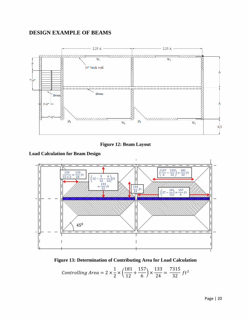
DESIGN EXAMPLE OF BEAMS
Figure 12: Beam Layout
Load Calculation for Beam Design
Figure 13: Determination of Contributing Area for Load Calculation
𝐶𝑜𝑛𝑡𝑟𝑜𝑙𝑙𝑖𝑛𝑔 𝐴𝑟𝑒𝑎 = 2 ×1
2× (
181
12+
157
6) ×
133
24=
7315
32 𝑓𝑡2

Page | 21
Bending Moment and Shear Force Diagram for Beam Design
Reactions at supports: (Assume the beam to have the following support conditions)
Figure 14: Determination Support Reactions
SFD and BMD
Page | 22
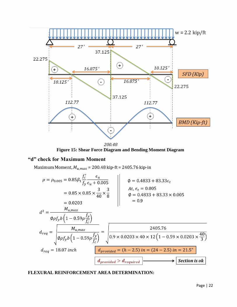
Figure 15: Shear Force Diagram and Bending Moment Diagram
“d” check for Maximum Moment
FLEXURAL REINFORCEMENT AREA DETERMINATION:
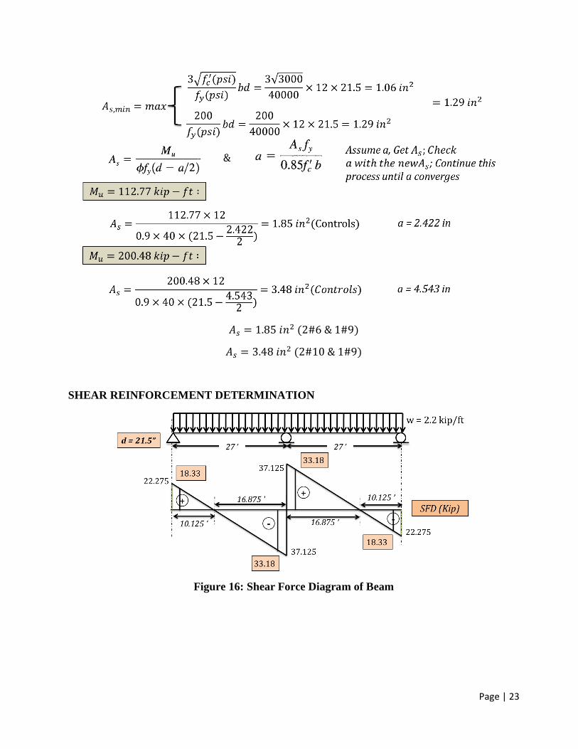
Page | 23
𝐴𝑠 = 1.85 𝑖𝑛2 (2#6 & 1#9)
𝐴𝑠 = 3.48 𝑖𝑛2 (2#10 & 1#9)
SHEAR REINFORCEMENT DETERMINATION
Figure 16: Shear Force Diagram of Beam

Page | 24
Figure 17: Distance determination where 𝑽𝒖 = ∅𝑽𝒄

Page | 25
Detailing of Beam Reinforcement
Figure 18: Beam Reinforcement Detailing Guideline
Figure 19: Beam Reinforcement Detailing According to the Design

Page | 26
3. DESIGN OF STAIR (USD)
Figure 20: Stair
Figure 21: Components of Stair

Page | 27
Figure 22: Parameters of Stair

Page | 28
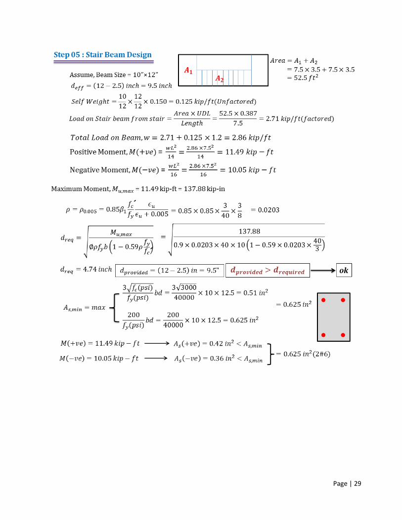
Page | 29
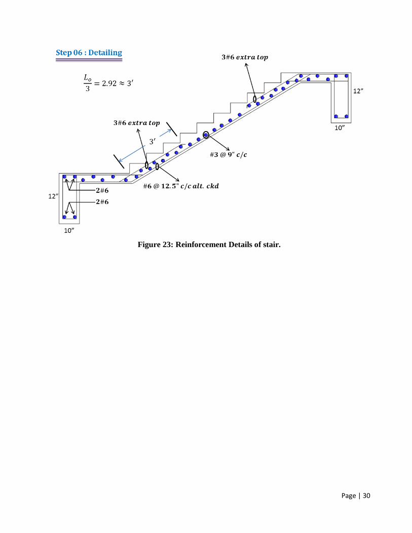
Page | 30
Figure 23: Reinforcement Details of stair.

Page | 31
4. DESIGN OF SUNSHADE (USD)
Figure 24: Section and Side View of a Wall with Window

Page | 32
Figure 25: Detailing of Sunshade

Page | 33
5. DESIGN OF LINTEL (USD)
Figure 26: Information necessary to determine lintel load
Figure 27: Loads come to Lintel from Slab

Page | 34
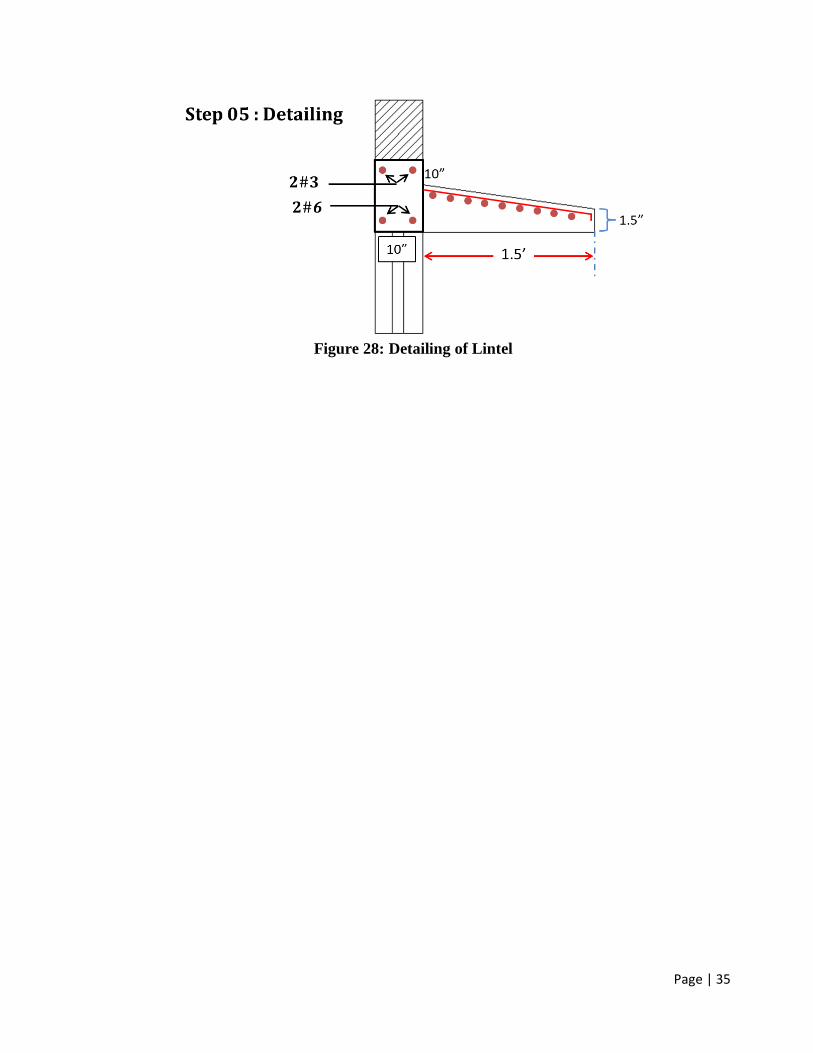
Page | 35
Figure 28: Detailing of Lintel

Page | 36
6. DESIGN OF BRICK FOUNDATION (WSD)
Design of brick foundation requires study and examination of multiple components, and it is the
main structure of any building, since it is the base of it.
Foundation Depths
The required depth of the foundation will depend on several factors like:
1. Soil bearing capacity: How much load the existing soil can withstand.
2. Type of soil: This depth will vary depending on the type of soil beneath the structure.
3. Depth of frost penetration in case of fine sand and silt.
4. Height of ground water table: This will usually be reported on the soil study.
5. The minimum depth should not be less than 18 inches to allow removal of top soil and
variations in ground level. However, depending on the structure, the engineer will select the best
depth.
Foundation Material
The foundation is usually built in brick work, masonry or concrete under the base of a wall or
column. This will enable to transfer the load to the soil in a uniform manner and allow the
transition from the structure to the soil. It will depend on the recommendation by the structural
engineer. For smaller and lightweight structures, the design will be different depending on the
material and location of the structure.
Usually dry and uniform graded dense materials should have maximum shear resistance and
maximum bearing capacity. In general submerged soil and clay have fewer bearing capacities,
reducing the capacity to handle loads imposed by the structure.
Foundation Design Precaution
The foundation will be designed in a way that loads will be transferred uniformly to the contact
surface. It should be designed to transmit the sum of dead load, live load and wind load to the
ground. The net loading capacity coming into the soil should not exceed the bearing capacity of the
soil. Settlements expected from the building will be design in such way that they will be controlled
and uniform for the complete structure to avoid damages to the structure. Whole design of the
foundation, super structure and characteristics of the ground should be studied to obtain benefits
during construction work.

Page | 37
Figure 29: Typical Brick Foundation
Design Procedure
1. Find the total load on foundation. Suppose the load is 135k considering all load of
superstructure on that particular foundation.
Then the total load P is (135+Self weight of the foundation under G.L) k.
Generally 10%-12% is considered as first assumption. For this example 10% load of
superstructure is added as self-weight. So the total load P is (135+13.5) = 148.5 k
2. Find the soil bearing capacity. Suppose soil bearing capacity is 3 ksf
Then the width of the foundation is B = 148.5×12
𝑠𝑜𝑖𝑙 𝑏𝑒𝑎𝑟𝑖𝑛𝑔 𝑐𝑎𝑝𝑎𝑐𝑖𝑡𝑦×𝑙𝑒𝑛𝑔𝑡ℎ 𝑜𝑓 𝑡ℎ𝑒 𝑓𝑜𝑢𝑛𝑑𝑎𝑡𝑖𝑜𝑛
= 148.5×12
3×22.5 where length of the foundation is 22.5 ft
= 26.4 inch required width but in brick foundation width
must be rounded to upper 5". So width for this foundation is 30".
3. Check the self-weight of the foundation whether it is less than the assumed value. If it is less
than the design is ok.

Page | 38
DESIGN EXAMPLE OF FOUNDATION
Figure 30: Contributing area of slab on brick wall
Figure 31: Loads on Foundation

Page | 39

Page | 40

Page | 41
Design of a slab bridge

Page | 42
Design of a slab bridge
Data and Specifications
Clear Span 15 ft
Clear width 26 ft
Live Loading HS20
Wearing surface 30 psf
Concrete strength fc’ 3000 psi
Grade 40 reinforcement
By AASHTO specifications, an allowable concrete stress of fc = 0.40 fc’ = 1200 psi
And an allowable steel stress of fs = 0.5 fy = 20,000 psi will be used
Slab Design
Assume trial slab thickness , t = 12 in
The effective span of the slab,S = 15 + 1 = 16 ft [for simple span the span length shall be the distance of
center to center of supports but shall not exceed clear span plus thickness of slab]
Total dead load = (t/12)*150 + wearing surface
= 180 psf
For a strip of 1 ft width Wdl = 180 lb/ft
Dead load moment, DLM = Wdl S2/8
= 180*16*16/8
= 5760 ft-lb
Total load on each rear wheel , P20= 16000 lb [for HS20 truck loading]
Width of slab over which wheel load is distributed,E = 4+0.06S [ for main reinforcement parallel to traffic]
= 4+0.06*16
= 4.96 ft
The load on unit width of slab, P = P20/E
=16000/4.96
=3230 lb

Page | 43
Live load moment, LLM = PS/4
=3230*16/4
= 12900 ft-lb
Impact coefficient, I = 50
𝑙+125≤ 0.3
Where l is the loaded length which is equal to effective span, S here
I = 50
𝑆+125
= 0.355>0.3
So I will be taken as 0.3
Impact moment, IM = Impact coefficient*Live load moment
= I*LLM
=0.3*12900
=3870 ft-lb
Total moment ,M = DLM+LLM+IM
=22,530 ft-lb
The design will be based on service load and the slab will be proportioned based on the cracked elastic
section
𝑘 =𝑛
𝑛 + 𝑟
Use n = 10 and r = fs/fc
k= 0.375
j = 1-k/3= 0.875
effective depth, dreqd = √2𝑀
fckjb = 10.7 in
dprovided= t-protective cover-half of main bar dia
= 12-1-0.5 [by providing #8 bar]
= 10.5

Page | 44
dprovidedis sufficiently close to dreqd
Reinforcement Calculation:
The required main reinforcement, As= 𝑀
fsjd =
22530∗12
20000∗0.875∗10.5 = 1.47 in2/ft
This is furnished by #8 bars 6 in on centers
Transverse reinforcement
For main reinforcement parallel to traffic transverse reinforcement Ast= As
√𝑆
= 0.37in2
#5 bars 10 in on centers are directly placed on top of the longitudinal reinforcement.
Curb design
To facilitate screeding off the slab the required curb will not be made monolithically.
The dead load carried by the edge beam = 22∗24
144∗ 150 = 550 𝑝𝑙𝑓
Dead load moment = 550*162/8 = 17600 ft-lb
The specified live load moment = 0.1*P20*S = 0.1*16000*16 = 25600 ft-lb
Total moment = 17600+25600 = 43200 ft-lb
The resisting moment of the given section,Mr = 0.5fckjbd2
= 0.5*1200*0.375*0.875*24*20.52/12=165474 ft-lb
Which is adequate
The steel required,As = 43200∗12
20000∗0.875∗20.5= 1.44 in2
Which will be provided by three No. 7 bar

Page | 45
3"
12"
1'-6"15'-0"1'-6"
2'-0"
2'-0"
#5@10"#8@6"
Longitudinal Section
#5 dowels @12"
3" bituminous surface
Crown 1¼ “
12"
Symmetrical about
Center line #8@6"
13'-0"
#5@10" 2'-0"3 - #7
#5dowels
@20"
10"
2 - #5
Tranverse Section

Page | 46
Design of a Deck Girder bridge

Page | 47
Design of a Deck Girder bridge
Data and Specifications
Clear Span 48 ft
Clear width 29 ft
Live Loading HS20
Concrete strength fc’ 3000 psi
Future protective cover 15 pf
Grade 40 reinforcement
The bridge will consist of six girders
By AASHTO specifications, an allowable concrete stress of fc = 0.40 fc’ = 1200 psi
And an allowable steel stress of fs = 0.5 fy = 20,000 psi will be used
2' 2'48'
Bridge Profile

Page | 48
Slab Design
Span = clear distance between girders [The slab will be poured monolithically with the girder and fully
continuous]
Assume the girder width = 14” and total slab thickness = 6” [including ¾ in wearing surface]
Clear span,S = 4 ft 4 in
Total dead load, Wdl = 6/12*150 + 15
= 90 psf
A coefficient of 1
10 will be used for both positive and negative moment
2'-9"5'-6"2'-9" 5'-6"
14'-6"
2'-0"
10"
6.5"
Transverse Section
Dead load moment, DLM = Wdl S2/10
= 1
10 *90*4.332
= 169 ft-lb
Total load on each rear wheel , P20= 16000 lb [for HS20 truck loading]
Page | 49
Live load moment, LLM = 𝑆+2
32∗P20 [for main reinforcement perpendicular to traffic]
For slabs continuous over three or more supports a continuity factor of 0.8 shall be applied to the above
formula
Live load moment, LLM = 𝑆+2
32∗P20
= 0.8*4.33+2
32*16000
= 2530 ft-lb
Impact coefficient, I = 50
𝑙+125≤ 0.3
Where l is the loaded length which is equal to clear span, S here
I = 50
𝑆+125
= 0.387>0.3
So I will be taken as 0.3
Impact moment, IM = Impact coefficient*Live load moment
= I*LLM
=0.3*2530
=760 ft-lb
Total moment ,M = DLM+LLM+IM
=3459 ft-lb
The design will be based on service load and the slab will be proportioned based on the cracked elastic
section
𝑘 =𝑛
𝑛 + 𝑟
Use n = 10 and r = fs/fc
k= 0.375
j = 1-k/3= 0.875
effective depth, dreqd = √2𝑀
fckjb = 4.19 in

Page | 50
dprovided= t-protective cover-half of main bar dia
= 6-1-0.5*0.75-0.75 [by providing #6 bar, 1 in protective cover and ¾” wearing surface]
= 3.875 in
dprovided is lower than dreqd
So 6.5 in slab will be used
Reinforcement Calculation:
The required main reinforcement, As= 𝑀
fsjd =
3459∗12
20000∗0.875∗4.37 = 0.54 in2/ft
This is furnished by #6 bars 10 in on centers
Transverse reinforcement
For main reinforcement perpendicular to traffic transverse reinforcement Ast= 2.20As
√𝑆
= 0.57 in2> 0.67* As = 0.36 in2
#5 bars 10 in on centers are directly placed on top of the longitudinal reinforcement.
Page | 51
Interior Girder Design
Interior girders are T beams with a flange width equal to the center to center distance of girders
[ based on ACI code]
Total moment calculation is done by following the steps listed below:
1. Dead load moment calculation:
a. Calculate total load from slab and assumed 14”X30” stem (below the slab)in plf
b. Calculate maximum dead load moment DLMmax[the girder will act like a simply
supported beam with uniformly distributed load]
c. Calculate DLM at one quarter and two quarter points of the span.
2. Live load moment calculation: For live load moment calculation both truck load moment
and lane loading moment needed to be calculated. Based on this calculation the governing Live
Load Moment, LLMmaxhas to be decided. Live load moment at one quarter and two quarter
points of the span have to also be calculated.
3. Impact moment calculation:
Impact moment, IMmax = Impact coefficient*Live load moment
Impact moment at one quarter and two quarter points of the span have also to be calculated.
Total Moment = DLMmax+ LLMmax+ IMmax
Total moment moment at one quarter and two quarter points of the span have also to be calculated.
Total shear calculation is done by following the steps listed below:
1. Dead load shear calculation: Calculate maximum dead load shear at the end of the beam
and at atone quarter and two quarter points of the span of the beam.

Page | 52
2. Live load shear calculation: Calculate maximum live load shear for truck loading and lane
loading at the end of the beam and atone quarter and two quarter points of the span of the beam.
Based on the above calculation decide the governing Live load shear.
3. Impact shear:
Impact shear, IS = Impact coefficient*Live load shear
Impact shear at one quarter and two quarter points of the span have also to be calculated.
Total shear (63400 psi) at the end of the beam and at one quarter and two quarter points of the span
have to be calculated.
Determination of cross section and steel area
According to AASHTO specification
Nominal shear stress at service load, v = V/bwd
Where bw = width of web.
In beam with web reinforcement the nominal shear stress, v may not exceed 4.95√fc’
In sizing the web area maximum shear force of 2.95√fc’ = 162 psi will be used
bwd =𝑉
𝑣 =
63,400
162 = 391 in2
asbw = 14 in, drequired = 28 in
if three rows of #11 bars are used with 2 in clear between rows and 2.5 in clear below the bottom
row to allow for stirrups and concrete protection a total depth of 34.56 in ( 28+2+2.5+1.5*11/8) is
obtained.
A total depth of 36 in will be used. The depth of the stem below the slab is then 36 - 6.5 = 29.5 in
which is so close to the assumed value that the dead load moments need not be revised.
The next step is tensile steel area calculation and web reinforcement calculation.
The final step is bar cut off

Page | 53
Exterior Girder Design
The exterior girders are identical in cross section with the interior girders cause the raised curb section will
be poured separately and cannot be counted in to participate in carrying loads.
Moment Calculation:
In addition to the total dead load obtained for the interior girders the safety curbs will add some extra load
(total 1215 plf).
By following the same procedure total moment and shear have to be calculated.
A portion of the wheel load which rests on the exterior slab panel is supported by the exterior girder.
That portion is obtained by placing the wheels as close to the curb as the clearance diagram will permit and
treating the exterior slab panel as a simple beam. The portion is shown in the following fig and the
proportion of the load is 4.25/5.5 = 0.773
2'-9"5'-6"2'-9" 5'-6"
4'-3" 1'-3"
14'-6"
6'-0" 2'-0"
2'-0"
Lateral Position of Wheel
The absolute maximum live load moment = 0.773
1.1*346000 = 243000 ft-lb
The impact moment is 0.285*243000 = 69300 ft-lb and the total maximum moment is 692300 ft-lb.

Page | 54
Shear Calculation:
The maximum dead load shear is VD = 1215*25 = 30400 lb
The maximum live load shear is proportional to the maximum live load shear in interior girder
VL =0.773
1.1 *30600 = 21500 lb
The impact shear is 6100 lb. The total shear at the support is then 58000 lb. Shear at other points are found
similarly.
Determination of cross section and reinforcement:
Once the shears and moments due to dead loads, live loads and impact are obtained the design of the
exterior girders would follow along the lines of that of interior girders.
3"13@9"=9'-9" 12@15"=15'-0" 5@20" = 8'-4"
2'-2"
8'-8"
3#11
4#11
4#11
2#6
#5 U stirrup12" diaphragm
12" diaphragm
6.5"
36"
Details of Interior Girder

Page | 55
Diaphragms: A transverse will be built between the girders at either end of the bridge. The chief
function of these diaphragm is to furnish lateral support to the girders, with some abutment details it also
serve to prevent the backfill from spilling out onto the bridge seats. A similar diaphragm will be built
between girders at midspan. Such intermediate diaphragms are required for all spans in excess of 40 ft and
serve to ensure that all girders act together in resisting loads.
Fixed bearing is provided at one end and expansion bearing is provided at the other end.
Water proofing and drainage: all joints will be filled with a mastic compound to prevent water from
seeping through the joints. Crowing is provided for quick drainage of the rain water.

Page | 56
REFERENCES
Bangladesh National Building Code (BNBC), 2006.
Arthur H. Nilson, David Darwin and Charles W. Dolan, Design of Concrete Structures, 13th
Edition, Mc-Graw Hill Publication.
Arthur H. Nilson, David Darwin and Charles W. Dolan, Design of Concrete Structures, 7th
Edition, Mc-Graw Hill Publication.
Design of RCC Members by WSD and USD Methods, Public Works Department (PWD),
1997.
Sushil Kumar, 2001, Building Construction, 19th Edition, Standard Publishers Distribution,
New Delhi.
Neville, A.M., Concrete Technology.