cdps-cs7 - kirikaeki.net
TRANSCRIPT

CDPS-CS7IP Master Controller
(Phase 1)
Operation ManualOperation Manual


DISCLAIMERSThe information in this manual has been carefully checked and is believed to be accurate. Cypress Technology assumes no responsibility for any infringements of patents or other rights of third parties which may result from its use.Cypress Technology assumes no responsibility for any inaccuracies that may be contained in this document. Cypress also makes no commitment to update or to keep current the information contained in this document.Cypress Technology reserves the right to make improvements to this document and/or product at any time and without notice.
COPYRIGHT NOTICENo part of this document may be reproduced, transmitted, transcribed, stored in a retrieval system, or any of its part translated into any language or computer file, in any form or by any means—electronic, mechanical, magnetic, optical, chemical, manual, or otherwise—without express written permission and consent from Cypress Technology.© Copyright 2018 by Cypress Technology.All Rights Reserved.
TRADEMARK ACKNOWLEDGMENTSAll products or service names mentioned in this document may be trademarks of the companies with which they are associated.
SAFETY PRECAUTIONSPlease read all instructions before attempting to unpack, install or operate this equipment and before connecting the power supply.Please keep the following in mind as you unpack and install this equipment:• Always follow basic safety precautions to reduce the risk of fire,
electrical shock and injury to persons.• To prevent fire or shock hazard, do not expose the unit to rain,
moisture or install this product near water.• Never spill liquid of any kind on or into this product.• Never push an object of any kind into this product through any
openings or empty slots in the unit, as you may damage parts inside the unit.
• Do not attach the power supply cabling to building surfaces.• Use only the supplied power supply unit (PSU). Do not use the PSU
if it is damaged.• Do not allow anything to rest on the power cabling or allow any
weight to be placed upon it or any person walk on it.• To protect the unit from overheating, do not block any vents or
openings in the unit housing that provide ventilation and allow for sufficient space for air to circulate around the unit.
• Please completely disconnect the power when the unit is not in use to avoid wasting electricity.
REVISION HISTORYREVISON DATE SUMMARY OF CHANGERDV1 27/11/17 Preliminary release
VS0 13/03/18 Initial technical review
VS0 21/03/18 Phase 1 technical review
VS0 20/07/18 Updated Sections 6.5.1, 6.5.3, 6.5.5
VS0 05/10/18 Updated Sections 6.5.1, 6.5.3, 6.5.6, 6.5.7, 6.6

CONTENTS
1. Introduction ......................................................12. Applications .....................................................13. Package Contents ..........................................24. System Requirements ......................................25. Features ............................................................26. Operation Controls and Functions .................3
6.1 Front Panel ................................................. 36.2 Rear Panel .................................................. 36.3 Remote Control ......................................... 46.4 IR Cable Pinouts ........................................ 46.5 WebGUI Control ........................................ 5
6.5.1 Monitor & Control Tab ..................... 76.5.2 Preset Recall Tab ............................. 86.5.3 System Tab ........................................ 96.5.4 Setup Wizard................................... 126.5.5 Setting Tab ...................................... 156.5.6 Transmitter Tab ............................... 176.5.7 Receiver Tab .................................. 19
6.6 Serial Control ........................................... 216.7 Telnet Control .......................................... 216.8 RS-232 and Telnet Commands .............. 22
7. Connection Diagram ....................................288. Specifications ................................................299. Acronyms .......................................................30

1
1. INTRODUCTIONThis controller is a powerful and flexible solution for controlling multiple Video over IP (VoIP) extenders within same network. The user only needs to install this unit into the same local network as the extenders (Transmitter and Receiver) to easily define and configure channel routing selections, for both unicast and multicast scenarios, using the WebGUI. It is also possible to define and switch routes using customized groups or presets allowing for easy control over multiple video zones. Without the use of this centralized unit, each individual Transmitter and Receiver in the system would need to be controlled and configured directly through their own WebGUI.Additionally, this unit supports controlling the matrix and video wall modes of connected VoIP units. The settings of all connected Transmitter/Receiver units, including IP address, netmask and extender status are clearly displayed within the WebGUI. The WebGUI is easily accessed via a web browser over a normal network connection or by directly connecting an HDMI display and USB keyboard & mouse to the unit. A trigger input interface is also provided to allow the easy addition of a remote control keypad, or other trigger-supporting products, which can be installed within a podium or within a table in a conference room or classroom. This interface can allow the user to activate stored presets with the simple press of a button. Standard control is available via WebGUI (remote or local), RS-232, Telnet and IR Remote.
2. APPLICATIONS• Video/TV wall display and control
• Security surveillance and control
• Commercial advertising, display and control
• Home Theaters with Smart Home Controls
• Retail sales and demonstration

2
3. PACKAGE CONTENTS• 1×IP Master Controller
• 1×5V/2.6A DC Power Adapter
• 1×Terminal Block (3-pin)
• 3×Terminal Block (5-pin)
• 1×3.5mm to IR Extender Cable
• 1×Remote Control (CR-183)
• 1×Shockproof Feet (Set of 4)
• 1×Operation Manual
4. SYSTEM REQUIREMENTSAn active network connection from a switch or router for control of compatible Video over IP devices.
5. FEATURES• Enables the management and configuration of multiple compatible
Video over IP (VoIP) extenders through a single WebGUI
• Supports point-to-point (unicast) and multi-to-multi (multicast) routing selections
• Control over both matrix and TV wall modes using WebGUI presets
• Definable display groups
• WebGUI clearly displays the status of all connected Transmitters and Receivers, including IP address, channel selection, etc.
• HDMI output displays the WebGUI and system status
• Supports the use of a USB mouse and keyboard to locally control the WebGUI (Optional)
• Can be powered by Ethernet switches supporting the IEEE 802.3af-2003 PoE standard (Optional)
• Trigger Control Keypad support for easy, single-button, preset activation (Optional)
• Standard control is available via WebGUI (remote or local), RS-232, Telnet, and IR Remote

3
6. OPERATION CONTROLS AND FUNCTIONS
6.1 Front Panel
POWER IR
IP Master Control
1 2
1 POWER LED: This LED will illuminate to indicate the unit is on and receiving power.
2 IR WINDOW: Accepts IR signals from the included IR remote for control of this unit only.
6.2 Rear Panel
LAN 1(POE) LAN 2USBHDMI OUTRS-232CONTROLIR EXTDC 5V
TRIGGER IN
TX RX
1 2 3 4 5 6 7 8 9
1 IR EXT: Connect to the provided IR Extender to extend the IR control range of the unit. Ensure that the remote being used is within direct line-of-sight of the IR Extender.
2 CONTROL: This port's functionality is reserved for use in a future update.
3 RS-232: Connect to a PC, laptop or other serial control device with a 3-pin adapter cable to control the unit via RS-232.
4 TRIGGER IN: Connect to the Trigger Control Keypad (OPTIONAL) or any device with trigger switch functionality such as window security alarms, motion detectors, door switches, etc. Each of the 8 trigger inputs will activate the associated preset (1 ~ 8) when triggered. A minimum of 5V DC is required to activate the trigger.
5 HDMI OUT: Connect to a standard HDMI display to view the unit’s current status information and access the WebGUI directly without a PC.

4
6 USB: Connect a USB mouse and keyboard to control the unit’s WebGUI displayed on the HDMI output port. Firmware update via USB is also supported.
Note: Specialized USB control devices, such as a touch panel, should be connected before the unit is powered on.
7 LAN 2: Connect directly, or through a network switch, to your PC/laptop to control the unit via WebGUI/Telnet.
8 LAN 1 (PoE): This port is used to connect to the Video over IP (VoIP) devices to be controlled. Connect to the VoIP units’ private network, either directly or through their dedicated network switch, to enable detection and control over those units.
Note 1: Typically the VoIP device network is contained within in a separate subnet or, more frequently, in a physically separate network.
Note 2: If the connected network switch supports the IEEE 802.3af-2003 PoE (Power over Ethernet) standard, this unit can optionally be powered directly via this Ethernet port.
9 DC 5V: Plug the 5V DC power adapter into the unit and connect it to an AC wall outlet for power. (Optional, not required if the unit is powered via PoE).
6.3 Remote Control
1 PRESET 1~8: Press any of the 8 buttons to activate the saved preset associated with that number.
6.4 IR Cable Pinouts
3
1
2
InfraredPowerGround
IR Extender
1

5
6.5 WebGUI Control
• Device Discovery ToolPlease obtain the “Device Discovery” software from your authorized dealer and save it in a directory where you can easily find it.Connect the unit and your PC/laptop to the same active network and execute the “Device Discovery” software. Click on “Find Devices on Network” and a list of devices connected to the local network will show up indicating their current IP address.
By clicking on one of the listed devices you will be presented with the network details of that particular device.
- IP Mode: If you choose, you can alter the static IP network settings for the device, or switch the unit into DHCP mode to automatically obtain proper network settings from a local DHCP server. To switch to DHCP mode, please select DHCP from the IP mode drop-down, then click “Save” followed by “Reboot”.
- WebGUI Hotkey: Once you are satisfied with the network settings, you may use them to connect via Telnet or WebGUI. The network information window provides a convenient link to launch the “WebGUI” directly.

6
• WebGUI Control PageAll functions of this unit are controllable via the built in WebGUI which is accessed by connecting your web browser to LAN 2’s IP address or by connecting an HDMI display to the unit’s HDMI output and attaching a USB mouse and keyboard to the unit’s USB port. This control is presented across a number of separate tabs, including Monitor & Control, Preset Recall, System, Setting, Transmitter, and Receiver. A setup wizard is also provided to help simplify first-time setup. The individual functions will be introduced in the following sections.When no user is logged in, a limited selection of tabs are available (Monitor & Control, Preset Recall, and System). This allows for easy user access to routing selection and presets while still protecting the more sensitive and critical setup and configuration controls. To log in to the WebGUI, switch to the System tab and click on the “Login” button. By default, both the Username and Password are set to “admin” for the WebGUI. The administrator password can be changed within the System tab of the WebGUI if desired.
i If you are unsure of the unit’s current LAN 2 IP address, please check the unit’s HDMI status display.
7
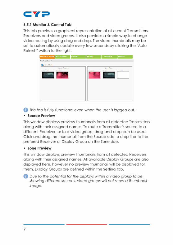
6.5.1 Monitor & Control TabThis tab provides a graphical representation of all current Transmitters, Receivers and video groups. It also provides a simple way to change video routing by using drag and drop. The video thumbnails may be set to automatically update every few seconds by clicking the "Auto Refresh" switch to the right.
i This tab is fully functional even when the user is logged out.• Source PreviewThis window displays preview thumbnails from all detected Transmitters along with their assigned names. To route a Transmitter’s source to a different Receiver, or to a video group, drag-and-drop can be used. Click and drag the thumbnail from the Source side to drop it onto the prefered Receiver or Display Group on the Zone side.
• Zone PreviewThis window displays preview thumbnails from all detected Receivers along with their assigned names. All available Display Groups are also displayed here, however no preview thumbnail will be displayed for them. Display Groups are defined within the Setting tab.
i Due to the potential for the displays within a video group to be showing different sources, video groups will not show a thumbnail image.

8
6.5.2 Preset Recall TabThis tab lists all currently defined Presets and provides a simple way to activate them. To activate a saved Preset, simply click on the appropriately named button. Presets are defined within the Setting tab.
i This tab is fully functional even when the user is logged out.

9
6.5.3 System TabThis tab provides access to system configuration options including IP configuration for both LAN ports, login and user management, access to the setup wizard, and firmware update functionality.
i This tab will only display system information and provide a Login button if the user is logged out. All other functions will be greyed out.
• LAN1 & LAN2The IP mode for each LAN port (DHCP, Static IP, or Auto IP), IP address, netmask, and gateway can be set here. When a LAN port is set to Auto IP mode it will automatically assign itself an APIPA address from the 169.254.XXX.XXX range. When a LAN port is set to “DHCP” mode, it will automatically attempt to obtain proper configuration information from the local DHCP server. If no DHCP server is available, or the user wishes to configure the network settings manually, please set the LAN port to “Static IP” mode and enter the information as appropriate for the connected network. Press “Save” to activate the changes.
i LAN1 defaults to "Auto IP" mode and is intended to be connected to the VoIP device network. LAN2 defaults to "DHCP" mode and is intended to be connected to a normal local network for easy access to the WebGUI.
• Login & LogoutClick these buttons to log in or log out of the WebGUI interface.
i When logged out, available WebGUI functionality is limited.• Change PasswordClick this button to change the WebGUI's administrator login password.

10
• ResetClick this button to clear all detected transmitter/receiver information, all groups and all presets.
i LAN settings will not be reset.• RebootClick this button to reboot the unit.
• WizardClick this button to launch the setup wizard.
i Activating the wizard will clear all detected transmitter/receiver information, all groups and all presets.
• FaviconThis allows for the upload of an icon image to use as the WebGUI's page/tab icon which is also commonly used by browsers when a web page has been bookmarked or added to favorites. The image file must be 16×16 pixels and saved in the *.ico format. The file must be named "favicon.ico". Click the “Choose File” button, select the file from your PC's file browser, then click the "Upload" button. Once the upload is complete, refresh the WebGUI to view the new icon.
• LogoThis allows for the upload of a small logo image that will be displayed in the upper left corner of the WebGUI. The image is recommended to be no taller than 90 pixels and must be saved in the *.png format. The file must be named "logo.png".Click the “Choose File” button, select the file from your PC's file browser, then click the "Upload" button. Once the upload is complete, refresh the WebGUI to view the corner logo.
• Firmware UpgradeIt is possible to update the firmware of this unit as well as to update the firmware of detected Transmitters and Receivers. The number of currently detected Transmitters and Receivers is also listed here.To update the unit's firmware, or the firmware of detected Transmitters or Receivers, click the “Choose File” button beneath the appropriate device type (IP Master Controller, Transmitter, or Receiver) to open the file selection window and then select an appropriate firmware update file (*.bin format) located on your local PC. After selecting the

11
file, click the “Upgrade” button beneath the appropriate device type to begin the firmware update process. Once the firmware update process has completed each updated unit will reboot.
i Thefirmwareupdateprocesscantakeseveralminutes,pleasedonot power the units off once the process has begun.

12
6.5.4 Setup WizardPressing the “Wizard” button will start the step by step Setup Wizard. It will also clear the unit’s stored Transmitter/Receiver history, Presets, and Groups. The following 4 windows will then be presented, in order, to simplify the initial setup of a new Video over IP routing installation. Prior to pressing the “Finish” button on the final page of the wizard, it is possible to move freely between all 4 steps of the Setup Wizard to make additional changes to the configuration. Once “Finish” has been pressed, the changes will be committed to all involved units and they will reboot.
(1) Transmitter SettingThis wizard step provides a way to control the detailed settings of each detected Transmitter. First, click on the “Scan” button to check the LAN 1 network for all available Transmitters. Once the list is populated with Transmitters, the settings for each can be modified (See the “Transmitter Tab” section for configuration details).
After all desired changes have been completed, press the “Next” button to move to the next wizard step.

13
(2) Receiver SettingThis wizard step provides a way to control the detailed settings of each detected Receiver. First, click on the “Scan” button to check the LAN 1 network for all available Receivers. Once the list is populated with Receivers, the settings for each can be modified (See the “Receiver Tab” section for configuration details).
After all desired changes have been completed, press the “Next” button to move to the next wizard step.
(3) Group SettingThis wizard step provides a way to define groups of displays that will all receive the same routed source when used in Presets or from the Monitor & Control tab (See the “Display Group Configuration” section for configuration details).
After all desired Display Groups have been defined, press the “Next” button to move to the next wizard step.

14
(4) Preset SettingThis wizard step provides a way to add, edit or remove routing Presets (See the “Preset Configuration” section for configuration details).
After all desired Presets have been defined, press the “Finish” button to complete the Setup Wizard and commit all setup changes. All involved units will reboot.

15
6.5.5 Setting TabThis tab allows for the assignment and configuration of routing Presets and Display Groups. Pressing the “Add” button in either section will open a new blank settings window for that section. Pressing the “Edit” button next to an existing Preset or Group item will open that settings window. Pressing the “Remove” button next to an existing Preset or Group item will delete it.
i This tab is not available when the user is logged out.• Preset ConfigurationThe Preset settings window provides a way to add, edit or remove routing Presets. Up to 250 Presets can be easily defined and managed.
Once the Preset settings window is open, the name of the Preset can be set at the top of the window. Pressing the “Add” button will add an additional Receiver/Group routing line. To delete an existing route, click on the “Remove” button next to the route to remove. Once all routes for the Preset have been defined, press the “Confirm” button to save the changes. Each route line has the following configurable settings:
- Receiver/Group: Use the dropdown to select a Receiver or Group

16
to route the selected source to. - Transmitter: Use the dropdown to select the Transmitter to route to
the selected Receiver/Group. - Vertical (Video Wall): Use the dropdown to define the number
of displays in the video wall, measured vertically. (Maximum is 8 displays.)
i If this route is not part of a video wall, leave the value at 1. - Horizontal (Video Wall): Use the dropdown to define the number
of displays in the video wall, measured horizontally. (Maximum is 8 displays.)
i If this route is not part of a video wall, leave the value at 1. - Row (Video Wall): Set the vertical position of the currently selected
display. (Counts top to bottom, from 0 to 7.)
i If this route is not part of a video wall, leave the value at 0. - Column (Video Wall): Set the horizontal position of the currently
selected display. (Counts top to bottom, from 0 to 7.)
i If this route is not part of a video wall, leave the value at 0.• Display Group ConfigurationThe Display Group device selection window provides a way to define a group of displays that will all receive the same routed source when used in Presets or from the Monitor & Control tab.
The name of the Display Group is set at the top of the window. To add Receivers to the Display Group, click on the name of each one to include. To remove a Receiver from the group, click on the Receiver’s name a second time. After all selections have been made, click on the “Confirm” button to save the changes.
17
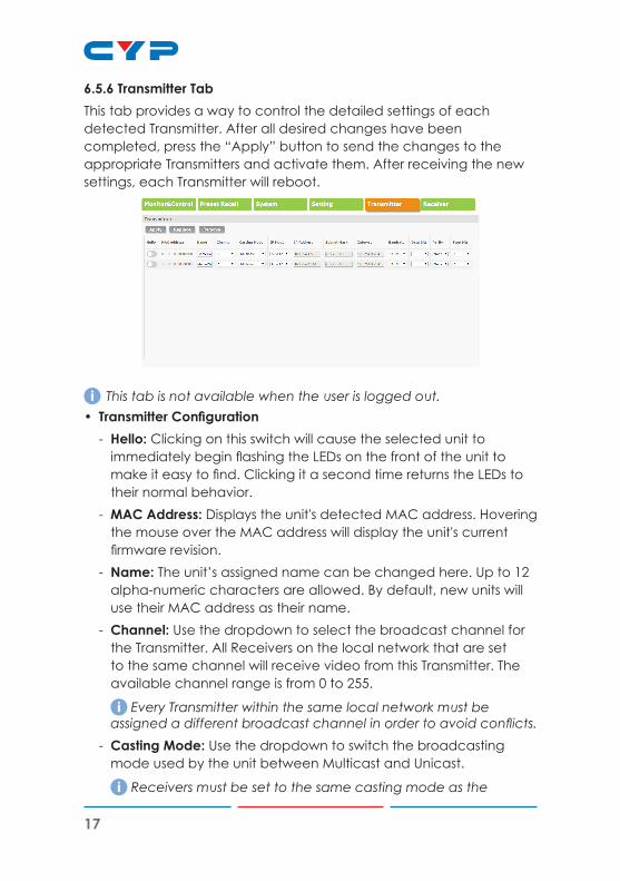
6.5.6 Transmitter TabThis tab provides a way to control the detailed settings of each detected Transmitter. After all desired changes have been completed, press the “Apply” button to send the changes to the appropriate Transmitters and activate them. After receiving the new settings, each Transmitter will reboot.
i This tab is not available when the user is logged out.• Transmitter Configuration
- Hello: Clicking on this switch will cause the selected unit to immediately begin flashing the LEDs on the front of the unit to make it easy to find. Clicking it a second time returns the LEDs to their normal behavior.
- MAC Address: Displays the unit's detected MAC address. Hovering the mouse over the MAC address will display the unit's current firmware revision.
- Name: The unit’s assigned name can be changed here. Up to 12 alpha-numeric characters are allowed. By default, new units will use their MAC address as their name.
- Channel: Use the dropdown to select the broadcast channel for the Transmitter. All Receivers on the local network that are set to the same channel will receive video from this Transmitter. The available channel range is from 0 to 255.
i Every Transmitter within the same local network must be assignedadifferentbroadcastchannelinordertoavoidconflicts.
- Casting Mode: Use the dropdown to switch the broadcasting mode used by the unit between Multicast and Unicast.
i Receivers must be set to the same casting mode as the

18
Transmitter in order to receive video. - IP Mode & IP Settings: The IP mode of each unit may be switched
between “Auto IP”, “DHCP” or “Static IP”. When the unit is set to Auto IP mode it will automatically assign itself an APIPA address from the 169.254.XXX.XXX range. When the unit is set to DHCP mode it will attempt to automatically obtain an IP address from a DHCP server. When the IP mode is set to static IP, you can manually set the IP address, netmask and gateway address.
i The default network setting is “Auto IP”. - Serial Settings: Set the desired baud rate, data bits, parity, and
stop bits for the unit’s RS-232 extension function.
i Linked Transmitters and Receivers must have the same serial settings.
• Replace and Remove TransmittersWhen a Transmitter has been removed from the local network, or is otherwise no longer accessible, and needs to be replaced, or removed completely, then the Replace and Remove buttons will provide that functionality.
- Replace: Click on this button to replace any currently listed Transmitter with a new unit. The pop-up window provides drop-downs to select the original unit, and the unit to replace it with. Once the selection has been made, click on "Confirm" to apply the change. Once the replace process has completed, the replaced unit will be removed from the list, and the new unit will have settings copied from the replaced unit.
- Remove: Click on this button to remove any Transmitter from the list of detected devices. The pop-up window provides a drop-down to select the unit to be removed. Once the selection has been made, click on "Confirm" to apply the change.

19
6.5.7 Receiver TabThis tab provides a way to control the detailed settings of each detected Receiver. After all desired changes have been completed, press the “Apply” button to send the changes to the appropriate Receivers and activate them. After receiving the new settings, each Receiver will reboot.
i This tab is not available when the user is logged out.• Receiver Configuration
- Hello: Clicking on this switch will cause the selected unit to immediately begin flashing the LEDs on the front of the unit to make it easy to find. Clicking it a second time returns the LEDs to their normal behavior.
- MAC Address: Displays the unit's detected MAC address. Hovering the mouse over the MAC address will display the unit's current firmware revision.
- Name: The unit’s assigned name can be changed here. Up to 12 alpha-numeric characters are allowed. By default, new units will use their MAC address as their name.
- Channel: Use the dropdown to select the broadcast reception channel for the Receiver. The Receiver will display the video stream from the Transmitter using the selected broadcast channel. The available channel range is from 0 to 255.
- Casting Mode: Use the dropdown to switch the network broadcast mode supported by the unit between Multicast and Unicast.
i Receivers must be set to the same casting mode as the Transmitter in order to receive video.
- IP Mode & IP Settings: The IP mode of each unit may be switched
20
between “Auto IP”, “DHCP” or “Static IP”. When the unit is set to Auto IP mode it will automatically assign itself an APIPA address from the 169.254.XXX.XXX range. When the unit is set to DHCP mode it will attempt to automatically obtain an IP address from a DHCP server. When the IP mode is set to static IP, you can manually set the IP address, netmask and gateway address.
i The default network setting is “Auto IP”. - Serial Settings: Set the desired baud rate, data bits, parity, and
stop bits for the unit’s RS-232 extension function.
i Linked Transmitters and Receivers must have the same serial settings.
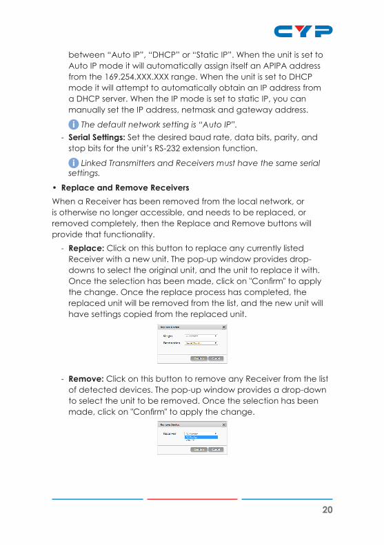
• Replace and Remove ReceiversWhen a Receiver has been removed from the local network, or is otherwise no longer accessible, and needs to be replaced, or removed completely, then the Replace and Remove buttons will provide that functionality.
- Replace: Click on this button to replace any currently listed Receiver with a new unit. The pop-up window provides drop-downs to select the original unit, and the unit to replace it with. Once the selection has been made, click on "Confirm" to apply the change. Once the replace process has completed, the replaced unit will be removed from the list, and the new unit will have settings copied from the replaced unit.
- Remove: Click on this button to remove any Receiver from the list of detected devices. The pop-up window provides a drop-down to select the unit to be removed. Once the selection has been made, click on "Confirm" to apply the change.

21
6.6 Serial Control
UNIT PC SERIAL PORT SETTINGSPin Pinout Pin Pinout Baud Rate 19200
1 Data Bits 8
1 TxD 2 RxD Parity Bit None
2 RxD 3 TxD Stop Bits 1
4 Flow Control None
3 GND 5 GND
6
7
8
9
6.7 Telnet Control
Before attempting to use Telnet control, please ensure that both the unit’s LAN 2 port and the PC/laptop are connected to the same active networks.
To Access the Command Line Interface (CLI)Windows 7 Click Start, type “cmd” in the search field, and
press Enter.Windows XP Click Start > Run, type “cmd”, and press Enter.Mac OS X Click Go > Applications > Utilities > Terminal.
Once in the CLI (Command Line Interface) type “telnet” followed by the IP address of the unit and “23”, then hit “Enter”. This will connect us to the unit we wish to control. Type “help” to list the available commands.

22
Note 1: By default the unit will obtain the LAN 2 IP address via DHCP. If you are unsure of the unit’s current LAN 2 IP address, please check the unit’s HDMI status display.Note 2: Commands will not be executed unless followed by a carriage return. Commands are not case-sensitive.Note 3: If the unit's IP address is changed then the IP address required for Telnet access will also change accordingly.
6.8 RS-232 and Telnet Commands
COMMANDSDESCRIPTION & PARAMETERS
System Commands
HELPShow the full command list.
GET_HARDWARE_VERSIONShow the unit’s hardware version.
GET_FIRMWARE_VERSIONShow the unit’s current firmware version.
SET_FACTORY_RESETReset the unit to the factory defaults.
SET_HISTORY_RESETClear the unit’s stored transmitter and receiver history list.
REBOOTReboot the unit.
Network Commands
GET_IPCONFIG N1Show the current Ethernet configuration of the selected port.
Available values for N1: 1 [LAN Port 1] 2 [LAN Port 2]

23
COMMANDSDESCRIPTION & PARAMETERS
SET_IP_MODE N1 N2Set the IP assignment mode for the selected LAN port.
Available values for N1: 1 [LAN Port 1] 2 [LAN Port 2]
Available values for N2: 0 [Static IP] 1 [DHCP] 2 [Auto IP]
GET_IP_MODE N1Show the IP assignment mode for the selected LAN port.
Available values for N1: 1 [LAN Port 1] 2 [LAN Port 2]
SET_IP_ADDRESS N1 N2Set the IP address for the selected LAN port.
Available values for N1: 1 [LAN Port 1] 2 [LAN Port 2]
N2 = X.X.X.X [X = 0 ~ 255]
GET_IP_ADDRESS N1Show the current IP address of the selected LAN port.
Available values for N1: 1 [LAN Port 1] 2 [LAN Port 2]

24
COMMANDSDESCRIPTION & PARAMETERS
SET_NETMASK N1 N2Set the netmask for the selected LAN port.
Available values for N1: 1 [LAN Port 1] 2 [LAN Port 2]
N2 = X.X.X.X [X = 0 ~ 255]
GET_NETMASK N1Show the current netmask of the selected LAN port.
Available values for N1: 1 [LAN Port 1] 2 [LAN Port 2]
SET_GATEWAY N1 N2Set the gateway address for the selected LAN port.
Available values for N1: 1 [LAN Port 1] 2 [LAN Port 2]
N2 = X.X.X.X [X = 0 ~ 255]
GET_GATEWAY N1Show the current gateway address of the selected LAN port.
Available values for N1: 1 [LAN Port 1] 2 [LAN Port 2]
Discovery Service Commands
GET_TX_DEVICEList all supported VoIP Transmitter devices detected on LAN port 1’s local network.

25
COMMANDSDESCRIPTION & PARAMETERS
GET_RX_DEVICEList all supported VoIP Receiver devices detected on LAN port 1’s local network.
Preset/Group Commands
SET_PRESET_RUN N1Activate Preset number N1.
N1 = 1 ~ 250 [Preset Number]
GET_PRESET_RUN N1List the contents of Preset number N1.
N1 = 1 ~ 250 [Preset Number]
SET_GROUP_ROUTE N1 N2Set all members of Group N1 to display Channel N2.
N1 = 1 ~ 255 [Group Number]
N2 = 0 ~ 255 [Channel Number]
GET_GROUP_MEMBER N1List all Receivers in Group N1.
N1 = 1 ~ 255 [Group Number]
Individual VoIP Unit Commands
SET_CHANNEL N1 N2Set the Channel for the Tx or Rx at IP address N1.
N1 = X.X.X.X [X = 0 ~ 255, IP of Target Unit]
N2 = 0 ~ 255 [Channel Number]
GET_CHANNEL N1Show the current Channel used by the Tx or Rx at IP address N1.
N1 = X.X.X.X [X = 0 ~ 255, IP of Target Unit]

26
COMMANDSDESCRIPTION & PARAMETERS
SET_DEVICE_NAME N1 N2Set the name of the Tx or Rx at IP address N1.
N1 = X.X.X.X [X = 0 ~ 255, IP of Target Unit]
N2 = {Name} [Alpha-numeric, 12 Chars Max]
GET_DEVICE_NAME N1Show the current name of the Tx or Rx at IP address N1.
N1 = X.X.X.X [X = 0 ~ 255, IP of Target Unit]
SET_NET_MODE N1 N2Set the network broadcast mode of the Tx or Rx at IP address N1.
N1 = X.X.X.X [X = 0 ~ 255, IP of Target Unit]
Available values for N2: 0 [Unicast Mode] 1 [Multicast Mode]
GET_NET_MODE N1Show the current network broadcast mode of the Tx or Rx at IP address N1.
N1 = X.X.X.X [X = 0 ~ 255, IP of Target Unit]
SET_VW_LAYOUT N1 N2 N3Set the horizontal and vertical display count of the video wall that the Rx at IP address N1 is a part of.
N1 = X.X.X.X [X = 0 ~ 255, IP of Target Unit]
N2 = 1 ~ 16 [Horizontal Display Count]
N3 = 1 ~ 16 [Vertical Display Count]
GET_VW_LAYOUT N1Show the horizontal and vertical display count of the video wall that the Rx at IP address N1 is a part of.
N1 = X.X.X.X [X = 0 ~ 255, IP of Target Unit]

27
COMMANDSDESCRIPTION & PARAMETERS
SET_VW_POS N1 N2 N3Set the horizontal and vertical position of the Rx at IP address N1 within the defined video wall.
N1 = X.X.X.X [X = 0 ~ 255, IP of Target Unit]
N2 = 0 ~ 15 [Horizontal Position]
N3 = 0 ~ 15 [Vertical Position]
Note:CannotexceedthedimensionsdefinedbyVW_LAYOUT.
GET_VW_POS N1Show the horizontal and vertical position of the Rx at IP address N1 within the defined video wall.
N1 = X.X.X.X [X = 0 ~ 255, IP of Target Unit]

28
7. CONNECTION DIAGRAM
LAN 1(POE) LAN 2USBHDMI OUTRS-232CONTROLIR EXTDC 5V
TRIGGER IN
TX RX
LINEOUT
MICIN OPT. OUT VGA OUT LAN 1(PoE)LAN 3 LAN 2HDMI OUT
DC 5VISP
DC 5VUSB VGA IN HDMI IN LINE IN LINE OUTLAN (PoE)
OR
Macro4
Macro6
Macro1
Macro3
Macro5
Macro7
Macro8
Macro2
2
1
3
4
5
6
8
7
9
10
11
12
CR-183
MARCO
7m3m 3m
60° LAN
LAN
LAN
LAN
LAN
USB
Serial Input
Trigger Input
IR Input
HDMI Output
Remote Control
Network Switch for VoIP Network
Network Switch for Local Network
Power Supply
VoIP Receiver
VoIP TransmitterLocal Monitor
USB Hub
Keyboad & Mouse
Serial/Ethernet Port Equipped PC Trigger Control
Keypad
29
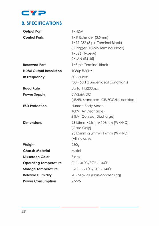
8. SPECIFICATIONSOutput Port 1×HDMI
Control Ports 1×IR Extender (3.5mm) 1×RS-232 (3-pin Terminal Block) 8×Trigger (10-pin Terminal Block) 1×USB (Type-A) 2×LAN (RJ-45)
Reserved Port 1×5-pin Terminal Block
HDMI Output Resolution 1080p@60Hz
IR Frequency 30 - 50kHz (30 - 60kHz under ideal conditions)
Baud Rate Up to 115200bps
Power Supply 5V/2.6A DC (US/EU standards, CE/FCC/UL certified)
ESD Protection Human Body Model: ±8kV (Air Discharge) ±4kV (Contact Discharge)
Dimensions 231.5mm×25mm×108mm (W×H×D) [Case Only] 231.5mm×25mm×117mm (W×H×D) [All Inclusive]
Weight 250g
Chassis Material Metal
Silkscreen Color Black
Operating Temperature 0˚C - 40˚C/32˚F - 104˚F
Storage Temperature −20˚C - 60˚C/−4˚F - 140˚F
Relative Humidity 20 - 90% RH (Non-condensing)
Power Consumption 2.99W

30
9. ACRONYMSACRONYM COMPLETE TERMCLI Command-Line Interface
DHCP Dynamic Host Configuration Protocol
GUI Graphical User Interface
HDMI High-Definition Multimedia Interface
IEEE Institute of Electrical and Electronics Engineers
IP Internet Protocol
IR Infrared
LAN Local Area Network
MAC Media Access Control
PC Personal Computer
PoE Power over Ethernet
TCP Transmission Control Protocol
USB Universal Serial Bus
VoIP Video over IP

CYPRESS TECHNOLOGY CO., LTD.www.cypress.com.tw