cdn115 devicenet specifications - · pdf filecdn115 devicenet specifications 29011520 revision...
TRANSCRIPT

29011520 Revision 2.0 07/99
CDN115DEVICENET
SPECIFICATIONS
CDN115 DeviceNet Specifications
29011520 Revision 2.0 07/99
Table of Contents
Overview......................................................................................................................................1
Hardware......................................................................................................................................2Processor ..........................................................................................................................2DeviceNet Interface .........................................................................................................2Digital I/O ........................................................................................................................3Analog Inputs...................................................................................................................3Analog Outputs ................................................................................................................3Power Distribution...........................................................................................................4Switches and Indicators ...................................................................................................4
MacID/BaudRate Option 1 ..................................................................................5MacID/BaudRate Option 2 ..................................................................................5
Connectors .......................................................................................................................5P2 I/O Header.......................................................................................................5DB-44 I/O Connector...........................................................................................6Front Panel Interface Header ...............................................................................6
DeviceNet Micro Connector ............................................................................................7
Specifications...............................................................................................................................8
Firmware ......................................................................................................................................9DeviceNet Message Types...............................................................................................9DeviceNet Class Services ................................................................................................9
DeviceNet Object Classes....................................................................................10
Identity Object Class Code: 01 (0x01).....................................................................................11Identity Object Class Attributes ...........................................................................11Identity Object Instance Attributes ......................................................................11Identity Common Services...................................................................................11
Identity Object Attributes.................................................................................................12Product Code – Attribute 3 ..................................................................................12Revision Information – Attribute 4......................................................................12Device Status – Attribute 5 ..................................................................................12Serial Number – Attribute 6.................................................................................12Device Name – Attribute 7 ..................................................................................13

CDN115 DeviceNet Specifications
29011520 Revision 2.0 07/99ii
Device State – Attribute 8....................................................................................13
Router Object Class Code: 02 (0x02).....................................................................................14Router Object Class Attributes ............................................................................14Router Object, Instance 1 Attributes....................................................................14Router Common Services ....................................................................................14
DeviceNet Object Class Code: 03 (0x03)..........................................................................15DeviceNet Object Class Attributes ......................................................................15DeviceNet Object, Instance 1 Attributes..............................................................15DeviceNet Object Common Services ..................................................................15
DeviceNet Object Attributes ............................................................................................15MacID – Attribute 1.............................................................................................15Data Rate – Attribute 2 ........................................................................................16Bus Off Interrupt – Attribute 3 ............................................................................16Bus Off Counter – Attribute 4 .............................................................................16Allocation Byte – Attribute 5...............................................................................16Mac Switch Changed – Attribute 6......................................................................16Baud Switch Changed – Attribute 7 ....................................................................17Mac Switch Value – Attribute 8 ..........................................................................17Baud Switch Value – Attribute 9 .........................................................................17
Assembly Object Class Code: 04 (0x04)...................................................................18Assembly Object Class Attributes ...................................................................................18Assembly Object, Instance 100 Attributes.......................................................................18Assembly Object, Instance 101 Attributes.......................................................................18Assembly Object Common Services................................................................................18Assembly Instance 100 ....................................................................................................19
Device Status .......................................................................................................19Digital Inputs .......................................................................................................19Pad Byte ...............................................................................................................19Analog Inputs.......................................................................................................19
Assembly Instance 101 ....................................................................................................19Digital Outputs.....................................................................................................19Pad Byte ...............................................................................................................19Analog Outputs ....................................................................................................20
Connection Object Class Code: 05 (0x05)..........................................................................21Connection Object Class Attributes.....................................................................21Connection Object, Instance 1 Attributes (Explicit Message) .............................21

CDN115 DeviceNet Specifications
29011520 Revision 2.0 07/99iii
Connection Object, Instance 2 Attributes (POLL connection) ............................22Connection Object Common Services .................................................................22
Discrete Input Point (DIP) Object Class Code: 08 (0x08).....................................................24DIP Object Class Attributes.................................................................................24DIP Object, Instance 1..16 Attributes ..................................................................24DIP Common Services.........................................................................................24Input State – Attribute 3.......................................................................................24
Discrete Output Point (DOP) Object Class Code: 09 (0x09).....................................................25DOP Object Class Attributes ...............................................................................25DOP Object, Instance 1..16 Attributes.................................................................25DOP Common Services .......................................................................................25Output State – Attribute 3 ....................................................................................25Fault State – Attribute 5.......................................................................................26Fault Value – Attribute 6 .....................................................................................26Idle State – Attribute 7.........................................................................................26Idle Value – Attribute 8 .......................................................................................26
Analog Input Point (AIP) Object ................................................................................................. Class Code: 10 (0x0A)AIP Object Class Attributes.................................................................................27AIP Object, Instance 1..2 Attributes ....................................................................27AIP Common Services.........................................................................................27
AIP Object Attributes ......................................................................................................27Value - Attribute 3 ...............................................................................................27Range – Attribute 7..............................................................................................27Type – Attribute 8 ................................................................................................27
Analog Output Point (AOP) Object Class Code: 11 (0x0B)....................................................28AOP Object Class Attributes ...............................................................................28AOP Object, Instance 1..2 Attributes...................................................................28AOP Common Services .......................................................................................28
AOP Object Attributes.....................................................................................................28Value – Attribute 3...............................................................................................28Range – Attribute 7..............................................................................................29Type – Attribute 8 ................................................................................................29Fault State – Attribute 9.......................................................................................29Idle State – Attribute 10.......................................................................................29Fault Value – Attribute 11 ...................................................................................30Idle Value – Attribute 12 .....................................................................................30

CDN115 DeviceNet Specifications
29011520 Revision 2.0 07/99iv
Device Supervisor Object Class Code: 48 (0x30).........................................................31Device Supervisor Object Class Attributes......................................................................31Configuration Object, Instance 1 Attributes ....................................................................31Device Supervisor Object Common Services..................................................................31Device Supervisor Object Attributes ...............................................................................31
Manufacturer Model – Attribute 6.......................................................................31Software Revision – Attribute 7 ..........................................................................32Hardware Revision – Attribute 8 .........................................................................32Device Status – Attribute 9 ..................................................................................32Exception Status – Attribute 12 ...........................................................................32Alarm Enable – Attribute 15................................................................................33Warning Enable – Attribute 16 ............................................................................33
Configuration Object Class Code: 64 (0x40).....................................................................34Configuration Object Class Attributes.............................................................................34Configuration Object, Instance 1 Attributes ....................................................................34Configuration Object Common Services .........................................................................34Configuration Reset Service ............................................................................................34Configuration Object Attributes ......................................................................................35
Mode Byte – Attribute 1 ......................................................................................35Num Digital Input – Attribute 2...........................................................................36Num Digital Output – Attribute 3........................................................................36Num Analog Input – Attribute 4 ..........................................................................36Num Analog Output – Attribute 5 .......................................................................36
Poll Packet Sizes..............................................................................................................37

CDN115 DeviceNet Specifications
29011520 Revision 2.0 07/99v
Revision History
Revision Description Date 1.0 First Release 11/97 2.0 Added Configuration Object
Added Device Supervisor ObjectUpgraded to Version 2.0 of ODVA objects
07/99

CDN115 DeviceNet Specifications
29011520 Revision 2.0 07/99
Overview
The CDN115 (Multifunction I/O) device operates as a slave on the DeviceNet network. Theunit supports Explicit Messages and Polled I/O Messages of the predefined master/slaveconnection set. It does not support the Explicit Unconnected Message Manager (UCMM).
The CDN115 includes a CCO Virtual Processor Object, 4 CCO Timers, 4 CCO Countersand 4 CCO Comparators. These objects allow self-contained combinatorial logic to beperformed locally on the node without intervention from a remote MASTER device.
A Virtual Processor Object defines an environment in which a series of instructions areexecuted to perform simple control algorithms. A Virtual Processor Object includes theinstruction storage, the control and status registers, the operating stack and storage registersused by the program.
The CCO Counter object provides a presetable down counter.
The CCO Timer object provides a presetable timer.
The CCO Comparator object provides a general purpose comparator.
Refer to the CDN115 CCO Specifications manual for further information.

CDN115 DeviceNet Specifications
29011520 Revision 2.0 07/992
Hardware
The CDN115 is available as both a board level controller as well as packaged in anextruded aluminum housing.
When used as a board level controller the DeviceNet interface, MacID/BaudRate switches,a user ‘reset’ signal and the DeviceNet status LED’s are available on a Front Panel InterfaceHeader compatible to the DIP298 and DIP398 Front panel assemblies, allowing thesefunctions to be remotely mounted from the unit.
A third allows the CDN115 to be used as a ‘daughter’ board. In these applications the FrontPanel Interface signals and the I/O signals are available on headers which my connect to auser supplied base module.
Processor
The CDN115 is implemented using a Motorola MC68HC705X32 processor which providesRAM (500 bytes), Flash (256 bytes) and E2PROM (32 Kbytes). The hardware platformsupports downloadable application code through an asynchronous serial connection port.The processor power on reset/monitoring is implemented with an external DS1233 powermonitor.
The processor section is powered from an isolated DC-DC power supply powered from theregulated +5 Vdc derived from the DeviceNet power. The Processor section is isolated fromthe Digital I/O and analog I/O subsystems.
DeviceNet Interface
The DeviceNet interface is connected through an 82C251 CAN transceiver. The Cantransceiver is powered from a DC-DC converter driven by the DeviceNet power. TheDeviceNet signals are routed a Front Panel Interface Header assembly for board levelapplications.
Rotary switches are provided to select the MacID and the Baud Rate. The MacID and BaudRate signals are brought to the Front Panel Interface Header for board level applications.
Standard Red/Green DeviceNet Network and Module status LED’s are mounted on thefront of the board.

CDN115 DeviceNet Specifications
29011520 Revision 2.0 07/993
Digital I/O
The Digital I/O is optically coupled to the processor. The active low MIC59P60 outputdrivers are interfaced through a serial bit interface. The individual outputs will support up to200 mA loads per channel. Based on package dissipation the maximum fully loaded outputcurrent is 100 mA (8 outputs) at 50 oC ambient. Each output is thermally protected for shortcircuit (500 mA typically) and includes under voltage protection. The output Fault State isaccessible through software. External schottky diodes are provided for output transientprotection and each I/O point is protected with a self-resetting poly fuse rated for 200 mA.Outputs default to the OFF condition during power up and processor reset conditions.
The digital output read back signals (inputs) are active low, with current limiting resistorssetting the short circuit current to 6 mA at 24 Vdc. The inputs are designed to retain theOFF State with currents below 2 mA and to ensure an ON state with currents above 4 mA.Each input circuit includes an indicator LED in series with the detection opto coupler. Boththe detection opto coupler and the indicator LED are protected with a shunt diode againstreverse voltage breakdown.
The digital I/O circuitry is powered from an on board +24 Vdc power source. The controlpower for the output drivers is derived from a linear +12 Vdc regulator. The +24 Vdc poweris protected with a self-resetting poly fuse rated at 2.5 Amps and a 36 transient suppressor.
The digital I/O signals and +24 Vdc power is connected directly to the I/O connector.
Analog Inputs
The Analog inputs are coupled directly to the processor and are implemented using aLTC1298 dual channel, 12 bit A/D. High impedance (1 Mohm) input buffering isprovided including a low pass filter (16 hertz). The analog inputs are connected directlyto the I/O Interface connector. The voltage reference for the output channel is supplied byan LT1121 precision reference.
The analog input circuitry is powered from an on board +/- 15 Vdc power source. The +15and -15 Vdc power is protected with a self-resetting poly fuse rated at 100 mA.
Analog Outputs
The analog outputs are implemented using two LTC1257 single channel 12 bit D/A’s with a0 to 10 Vdc output range. The output drivers are capable of driving 2 Kohm (5 mA) outputloads. The analog output signals are connected directly to the I/O Interface connector.Analog outputs default to 0 volts during power up and processor reset conditions.

CDN115 DeviceNet Specifications
29011520 Revision 2.0 07/994
The analog output power is derived from the same +/- 15 Vdc power used for the analoginputs. The voltage reference for the output channel is supplied by an LT1021 precisionreference.
Power Distribution
Power for the module is derived from the DeviceNet power (11 – 25 Vdc). Isolated DC-DCconverters are used to derive secondary power requirements and to maintain isolationbetween the subsystems. The analog circuitry requires +/- 15 Vdc and is fully isolated fromthe processor. The Digital I/O circuitry is fully isolated from the Processor and Analog I/Oand is powered by an onboard +24 Vdc source.
DC-DC (+5 Vdc) Isolated DC-DC (+5 Vdc)
11 – 25 Vdc +5 VdcDeviceNet Pwr Processor +Analog
+5 Vdc Can Transceiver +15 Vdc (analog)
- 15 Vdc (analog)
Digital I/O+24 Vdc
Switches and Indicators
The CDN115 includes 8 Green I/O status LED’s which are wired directly to the I/O points.The LED is ON if the corresponding I/O point is ON.

CDN115 DeviceNet Specifications
29011520 Revision 2.0 07/995
Two DeviceNet indicators are provided, Network Status and Device Status per the ODVADeviceNet specification.
MacID/BaudRate Option 1
Two BCD switches (S1 and S2) are installed on the board to allow setting the MacID.Values greater than 63 result in the switch being disabled and the last valid switch valuewill be used. The switches are read only during power up.
A BCD switch (S3) is installed on the board to allow setting the Data Rate. Setting theswitch to a value greater than 2 result in the switch being disabled and the last valid baudrate value will be used. The switch setting is read only during power up.
MacID/BaudRate Option 2
The signals for the MacID and BaudRate switch are also available on the Front PanelInterface header which mates to the DIP298/398 front panel assemblies. When this option isto be used the onboard switches must be set in the ‘0’ position. Refer to the DIP298/398documentation for further information.
Connectors
The CDN115 has 3 connector sets: a DB-44 I/O interface connector, a 26 pin I/Ointerface header for daughter board applications and a 26 pin Front Panel Interface headerfor use in daughter board applications or with the DIP298/398 front panel assemblies.
P2 I/O Header
Pin Description Pin Description 1 DGND 2 AGND 3 DIO0 4 AIN0 5 DIO1 6 AGND 7 DIO2 8 AIN1 9 DIO3 10 AGND 11 DIO4 12 AOUT0 13 DIO5 14 AGND 15 DIO6 16 AOUT1 17 DIO7 18 AGND 19 DGND 20 DGND 21 +24 Vdc 22 +24 Vdc 23 DGND 24 DGND 25 -15 Vdc 26 +15 Vdc

CDN115 DeviceNet Specifications
29011520 Revision 2.0 07/996
DB-44 I/O Connector
Pin Description Pin Description Pin Description 1 DGND 16 DGND 31 AGND 2 DIO0 17 DIO4 32 AIN0 3 +24 Vdc 18 +24 Vdc 33 AGND 4 DGND 19 DGND 34 AIN1 5 DIO1 20 DIO5 35 AGND 6 +24 Vdc 21 +24 Vdc 36 AOUT0 7 DGND 22 DGND 37 AGND 8 DIO2 23 DIO6 38 AOUT1 9 +24 Vdc 24 +24 Vdc 39 AGND 10 DGND 25 DGND 40 +15 Vdc 11 DIO3 26 DIO7 41 - 15 Vdc 12 +24 Vdc 27 +24 Vdc 42 +24 Vdc 13 BUS + 28 BUS + 43 BUS + 14 BUS - 29 BUS - 44 BUS - 15 DGND 30 DGND
Front Panel Interface Header
Pin Description Pin Description 1 SGND 2 SGND 3 MACID0 4 MOD GREEN 5 MACID1 6 MOD RED 7 MACID2 8 NET GREEN 9 MACID3 10 NET RED 11 MACID4 12 RESET/ 13 MACID5 14 CANH 15 MACID6 16 CANL 17 BRATE0 18 +5Vdc 19 BRATE1 20 CONFIG DET. 21 BUS - 22 BUS - 23 BUS + 24 BUS + 25 SGND 26

CDN115 DeviceNet Specifications
29011520 Revision 2.0 07/997
DeviceNet Micro Connector
The DeviceNet connector uses the standard ODVA pinout for micro-DIN connectors.
CDN067-3 Connector (Male) 1 - Drain (bare) 2 - V+ (red) 4 3 3 - V- (black) 4 - CAN_H (white) 5 5 - CAN_L (grey) 1 2 3 4 5 2 1
Mating Connector (Female)

CDN115 DeviceNet Specifications
29011520 Revision 2.0 07/998
Specifications
Specification Min Typ. Max Description/notesDeviceNet ISO 11898 transceiver, optically coupled MacID 0 63 Hardware settable (switch/backplane), Software
settable Data Rate 125 500 Kbit/second, hardware or software settable Vpwr 11 25 Vdc Ipwr 250 400 mA at 24 Vdc
Digital Inputs 8 Channels, linked to Digital Outputs Ion -4 mA Ioff -2 mA – Corresponding output must be in OFF state Vin -1 28 Vdc
Digital Outputs 8 Channels, linked to Digital Inputs Ion 100 200 Individual channels will drive up to 200 mA.
Dissipation should be limited to 800 mA for eachgroup of 8 channels, averaging 100 mA / channel.
Ioff .1 mA Off leakage current for voltages less than VDIO
VOL .91.1
1.11.2
@ 100 mA load@ 200 mA load
Digital Power VDIO 18 24 28 Vdc. IDIO 40 mA + 6 mA / active I/O point
Analog Inputs 2 Channels Resolution 12 Bits Input Range 0-10 Vdc Filtering 16 hertz, low pass Impedance 1 M Ohms input impedance
Analog Outputs 8 Channels Resolution 12 Bits Output Range 0 to +10 Vdc Output Drive 2000 Ohms output load impedance

CDN115 DeviceNet Specifications
29011520 Revision 2.0 07/999
Firmware
The CDN115 supports DeviceNet using ODVA standard Digital Input Points (DIP’s),Digital Output Points (DOP’s), Analog Input Points (AIP’s), and Analog Output Points(AOP’s). The unit operates as a group II Slave. Additional objects include a User Definedconfiguration object and a set of Combinatorial Control Objects (CCO) that allow controlprograms to be executed directly on the module.
DeviceNet Message Types
The CDN115 supports the following Group 2 message types.
CAN IDENTIFIER GROUP 2 Message Type10xxxxxx111 Duplicate MACID Check Message10xxxxxx110 Unconnected Explicit Request Message10xxxxxx101 Master I/O Poll Command Message10xxxxxx100 Master Explicit Request Message
xxxxxx = Node Address
The CDN115 supports the Group 4 Offline Connection set.
CAN IDENTIFIER GROUP 2 Message Type11111101100 Communication Faulted Response Message11111101101 Communication Faulted Request Message11111101110 Communication Ownership Response Message11111101111 Communication Ownership Request Message
DeviceNet Class Services
The CDN115 supports the following class services and instance services.
SERVICE CODE SERVICE NAME05 (0x05) Reset14 (0x0E) Get Attribute Single16 (0x10) Set Attribute Single75 (0x4B) Allocate Group 2 Identifier Set76 (0x4C) Release Group 2 Identifier Set

CDN115 DeviceNet Specifications
29011520 Revision 2.0 07/9910
DeviceNet Object Classes
The CDN115 device supports the following DeviceNet object classes.
CLASS CODE OBJECT TYPE01 (0x01) Identity02 (0x02) Router03 (0x03) DeviceNet04 (0x04) Assembly05 (0x05) Connection08 (0x08) Digital Input Point09 (0x09) Digital Output Point10 (0x0a) Analog Input Point11 (0x0b) Analog Output Point50 (0x32) Device Supervisor Object64 (0x40) Configuration Object80 (0x50) Virtual Processor Object *81 (0x51) Counter Object *82 (0x52) Timer Object *83 (0x53) Comparator Object *
Refer to the D.I.P. CCO Support documentation for further information on CCO controlfunctions.

CDN115 DeviceNet Specifications
29011520 Revision 2.0 07/9911
Identity Object Class Code: 01 (0x01)
The Identity Object is required on all devices and provides identification of and generalinformation about the device.
Identity Object Class Attributes
Attribute Access Name Type Value1 Get Revision UINT 12 Get Max Object Instance UINT 16 Get Max Class Identifier UINT 77 Get Max Instance Attribute UINT 7
Identity Object Instance Attributes
Attribute Access Name Type Value1 Get Vendor UINT 592 Get Product Type UINT 73 Get Product Code UINT 14 Get Revision STRUCT OF
Major Revision USINT 1 Minor Revision USINT 1
5 Get Device Status UINT (1)6 Get Serial Number UINT (2)7 Get Product Name STRUCT OF
Length USINT 6 Name STRING [6] CDN115
Identity Common Services
Service Code Class Instance Service Name05 (0x05) No Yes Reset14 (0x0E) Yes Yes Get_Attribute_Single

CDN115 DeviceNet Specifications
29011520 Revision 2.0 07/9912
Identity Object Attributes
Product Code – Attribute 3
The Product code is fixed at 7904 for the CDN494. The product code is used within theElectronic Data Sheet format to uniquely identify the product type.
Revision Information – Attribute 4
D.I.P. maintains strict version control. The major revision number will increment asfunctional enhancements are implemented. The minor firmware revision control number isincremented if minor changes are incorporated.
Device Status – Attribute 5
Bit Number Name Meaning 0 Owned = 0, not owned
= 1, allocated 1 Reserved 2 Configured = 0, not configured – this bit is not supported 3 Reserved 4-7 User defined 8 Minor Recoverable fault = 0, no fault
= 1, minor recoverable faults (DOP short circuit) 9 Minor Unrecoverable fault = 0, no fault
= 1, minor unrecoverable faults 8 Major Recoverable fault = 0, no fault
= 1, major recoverable faults (Loss of +24 Vdc) 9 Major Unrecoverable fault = 0, no fault
= 1, major unrecoverable faults (Checksum, A/D) 12-15 Reserved
Serial Number – Attribute 6
The serial number is encoded in the product during the manufacturing cycle and isguaranteed to be unique across all product lines produced by D.I.P.

CDN115 DeviceNet Specifications
29011520 Revision 2.0 07/9913
Device Name – Attribute 7
The DeviceName provides a character arry containing the short string CDN494 orCDN494-1.
Device State – Attribute 8
The Device State reflects whether any errors have occurred and the severity. The followingstates are supportted. The only exit from a Major Unrecoverable fault condition is powercycling the device.
State Interpretation Causes 0 Non-existent 1 Self Test 2 Standby 3 Operating Normal operating mode 4 Major Recoverable fault Loss of +24 Vdc or +/-15 Vdc power 5 Major Unrecoverable fault Memory Checksum failure

CDN115 DeviceNet Specifications
29011520 Revision 2.0 07/9914
Router Object Class Code: 02 (0x02)
The Message Router Object provides a messaging connection point through which a Clientmay address a service to any object class or instance residing in the physical device.
Router Object Class Attributes
Attribute Access Name Type Value1 Get Revision UINT 16 Get Max Class Identifier UINT 77 Get Max Instance Attribute UINT 2
Router Object, Instance 1 Attributes
Attribute Access Name Type Value2 Get Number of
ConnectionsUINT 2
Router Common Services
Service Code Class Instance Service Name14 (0x0E) Yes Yes Get_Attribute_Single

CDN115 DeviceNet Specifications
29011520 Revision 2.0 07/9915
DeviceNet Object Class Code: 03 (0x03)
The DeviceNet object provides general information on the specific node.
DeviceNet Object Class Attributes
Attribute Access Name Type Value1 Get Revision UINT 2
DeviceNet Object, Instance 1 Attributes
Attribute Access Name Type Value1 Get/Set MACID USINT (1)2 Get/Set Baud Rate USINT (2)3 Get/Set Bus Off Interrupt BOOL (3)4 Get/Set Bus Off Counter USINT (4)5 Get/Spc Allocation Information STRUCT of (5)
Choice Byte BYTE Master Node Addr. USINT
DeviceNet Object Common Services
Service Code Class Instance Service Name14 (0x0E) Yes Yes Get_Attribute_Single16 (0x10) No Yes Set_Attribute_Single75 (0x4B) No Yes Allocate Master/Slave76 (0x4C) No Yes Release Master/Slave
DeviceNet Object Attributes
MacID – Attribute 1
The MACID is set using two BCD rotary switches located on the module. Valid MACIDaddresses are 0 to 63 (0 to 3F Hex). Setting the switch address to a value greater than 63will disable the switch and allow software setting of the MACID. The software settingdefaults to the last hardware setting. The switch is only read during power up.

CDN115 DeviceNet Specifications
29011520 Revision 2.0 07/9916
The MacID may also be set through connections on the Front Panel Interface header. Theseactive low inputs form a BCD encoded value in the range 00 – 63. Connecting an inputsignal to the SGND signal turns the corresponding bit ‘ON’.
Data Rate – Attribute 2
The Data Rate is set using a BCD switch. Valid Data Rates are 0 to 2. The software settingdefaults to the last hardware setting. The switch is read during power up.
The Data Rate may also be set through connections on the Front Panel interface header.These active low inputs form a BCD encoded value in the range 0 – 2. Connecting an inputsignal to the SGND Common signal turns the corresponding bit ‘ON’.
Bus Off Interrupt – Attribute 3
Bus Off Interrupt (BOI) determines the action if a Bus Off state is encountered.
BOI Action
0 Hold chip in OFF state (default) 1 If possible reset CAN chip
Bus Off Counter – Attribute 4
Bus Off Counter will be forced to 0 whenever set regardless of the data value provided.
Allocation Byte – Attribute 5
Allocation_bytebit 0 explicitset to 1 to allocatebit 1 polled set to 1 to allocatebit 2-7 reserved (always 0)
Mac Switch Changed – Attribute 6
The Mac Switch Changed flag will be set if the Mac Switch has changed since the lastpower up sequence. Note that if the Mac Switch is set in the ‘disabled’ or ‘program’position it is considered to be removed from the circuit and reading this attribute will resultin an ‘Attribute Not Supported’ error response.

CDN115 DeviceNet Specifications
29011520 Revision 2.0 07/9917
Baud Switch Changed – Attribute 7
The Baud Switch Changed flag will be set if the Baud Switch has changed since the lastpower up sequence. Note that if the Baud Switch is set in the ‘disabled’ or ‘program’position it is considered to be removed from the circuit and reading this attribute will resultin an ‘Attribute Not supported’ error response.
Mac Switch Value – Attribute 8
The Mac Switch Value attribute returns the actual state of the Mac Switch. Note that if theMac Switch is set in the ‘disabled’ or ‘program’ position it is considered to be removedfrom the circuit and reading this attribute will result in an ‘Attribute Not Supported’ errorresponse.
Baud Switch Value – Attribute 9
The Baud Switch Value attribute returns the actual state of the Baud Switch. Note that if theBaud Switch is set in the ‘disabled’ or ‘program’ position it is considered to be removedfrom the circuit and reading this attribute will result in an ‘Attribute Not Supported’ errorresponse.

CDN115 DeviceNet Specifications
29011520 Revision 2.0 07/9918
Assembly Object Class Code: 04 (0x04)
The Assembly Objects bind attributes of multiple objects to allow data to or from eachobject to be sent or received over a single connection.
Assembly Object Class Attributes
Attribute Access Name Type Value1 Get Revision UINT 12 Get Max Class ID UINT 101
Assembly Object, Instance 100 Attributes
Attribute Access Name Type Value3 Get Data STRUCT of (1)
Supervisor Status BYTE See ConfigurationClass
Digital Inputs BYTE[] See ConfigurationClass
Pad Byte BYTE See ConfigurationClass
Analog Inputs UINT[] See ConfigurationClass
Assembly Object, Instance 101 Attributes
Attribute Access Name Type Value3 Get/Set Data STRUCT of (3)
Digital Outputs BYTE See ConfigurationClass
Pad Byte BYTE See ConfigurationClass
Analog outputs UINT[8] See ConfigurationClass
Assembly Object Common Services
Service Code Class Instance Service Name14 (0x0E) Yes Yes Get_Attribute_Single16 (0x10) No Yes Set_Attribute_Single

CDN115 DeviceNet Specifications
29011520 Revision 2.0 07/9919
Assembly Instance 100
Assembly instance 100 is used to generate the POLL response packet and consists of avariable number of bytes as determined by the configuration object.
Device Status
The Device Status byte, if included, provides overall information on the device as defined inthe Device Supervisor object.
Digital Inputs
The digital input byte(s) provide information on the digital input states. The number ofbytes included is defined in the configuration object.
Pad Byte
The pad byte, if included, provides a single byte pad to ensure that the analog input valuesare positioned on an even byte boundary.
Analog Inputs
The number of analog inputs included is defined in the configuration object. The analoginputs are presented as low byte, followed by high byte.
Assembly Instance 101
Assembly instance 101 is used to consume the POLL request packet and consists of avariable number of digital output states, the desired analog input range selection, paddingbytes and a variable number of analog output values as determined by the configurationobject.
Digital Outputs
The digital output byte(s) set the state of the digital outputs. The number of bytes includedis defined in the configuration object.
Pad Byte

CDN115 DeviceNet Specifications
29011520 Revision 2.0 07/9920
The pad byte, if included, provides a single byte pad to ensure that the analog output valuesare positioned on an even byte boundary.
Analog Outputs
The number of analog inputs included is defined in the configuration object. The analogoutputs are presented as low byte, followed by high byte.

CDN115 DeviceNet Specifications
29011520 Revision 2.0 07/9921
Connection Object Class Code: 05 (0x05)
The Connection Objects manage the characteristics of each communication connection. Asa Group II Only Slave device the unit supports one explicit message connection and a POLLmessage connection.
Connection Object Class Attributes
Attribute Access Name Type Value1 Get Revision UINT 1
Connection Object, Instance 1 Attributes (Explicit Message)
Attribute Access Name Type Value1 Get State USINT (1)2 Get Instance Type USINT 0 = Explicit Message3 Get Transport Class
TriggerUSINT 0x83
4 Get Production Connection UINT (2)5 Get Consumed Connection UINT (2)6 Get Initial Comm. Char. USINT 0x217 Get Production Size UINT 188 Get Consumed Size UINT 229 Get/Set Expected Packet Rate UINT default 2500 msec12 Get Timeout Action USINT 1 = AutoDelete13 Get Prod. Path Length USINT 014 Get Production Path (null)15 Get Cons. Path Length USINT 016 Get Consumed Path (null)17 Get Inhibit Timer UINT 0

CDN115 DeviceNet Specifications
29011520 Revision 2.0 07/9922
Connection Object, Instance 2 Attributes (POLL connection)
Attribute Access Name Type Value1 Get State USINT (1)2 Get Instance Type USINT 1 = I/O Message3 Get Transport Class
TriggerUSINT 0x82
4 Get Production Connection UINT (2)5 Get Consumed Connection UINT (2)6 Get Initial Comm. Char. USINT 0x17 Get Production Size UINT See Configuration Obj8 Get Consumed Size UINT See Configuration Obj9 Get/Set Expected Packet Rate UINT default 2500 msec12 Get/Set Timeout Action USINT (3)13 Get Prod. Path Length USINT 614 Get Production Path STRUCT of
Log. Seg., Class USINT 0x20 Class Number USINT 0x04 Log.Seg., Instance USINT 0x24 Instance Number USINT 0x64 Log.Seg., Attribute USINT 0x30 Attribute Number USINT 0x03
15 Get Cons. Path Length USINT 616 Get Production Path STRUCT of
Log. Seg., Class USINT 0x20 Class Number USINT 0x04 Log.Seg., Instance USINT 0x24 Instance Number USINT 0x65 Log.Seg., Attribute USINT 0x30 Attribute Number USINT 0x03
17 Get Inhibit Timer UINT 0
Connection Object Common Services
Service Code Class Instance Service Name05 (0x05) Yes Yes Reset14 (0x0E) Yes Yes Get_Attribute_Single16 (0x10) No Yes Set_Attribute_Single

CDN115 DeviceNet Specifications
29011520 Revision 2.0 07/9923
(1) Connection States:
0 = non-existent1 = configuring3 = established4 = timed out
(2) Connection ID's:
Connection 1 Produced Connection ID: 10xxxxxx011Connection 1 Consumed Connection ID: 10xxxxxx100
Connection 2 Produced Connection ID: 01111xxxxxxConnection 2 Consumed Connection ID: 10xxxxxx101
xxxxxx = Node Address.
(3) Watch Dog Timeout Activity:
0 = Timeout (default)1 = Auto Delete (Explicit Message, non modifiable)2 = Auto Reset

CDN115 DeviceNet Specifications
29011520 Revision 2.0 07/9924
Discrete Input Point (DIP) Object Class Code: 08 (0x08)
The Discrete Input Point (DIP) Object models discrete inputs in a product. There is aseparate instance for each discrete input available on the device.
DIP Object Class Attributes
Attribute Access Name Type Value1 Get Revision UINT 12 Get Max Object Instance UINT 166 Get Max Class Identifier UINT 77 Get Max Instance Attribute UINT 3
DIP Object, Instance 1..16 Attributes
Attribute Access Name Type Value3 Get Value BOOL (1)
DIP Common Services
Service Code Class Instance Service Name14 (0x0E) Yes Yes Get_Attribute_Single
Input State – Attribute 3
Attribute 3 provides the state of the specific digital input. A value of 0 indicates an OFFstate and a value of 1 indicates an ON state. The Digital inputs provide feedback of thedigital output states. If the corresponding output state is set to 0 these points may be used asinputs.
Inputs 1..8 are mapped to the physical DIO input points. Inputs 9..16 are mapped to internalholding registers which may be used by CCO program or other system needs. All inputs aremapped to corresponding DOP outputs.

CDN115 DeviceNet Specifications
29011520 Revision 2.0 07/9925
Discrete Output Point (DOP) Object Class Code: 09 (0x09)
The Discrete Output Point (DOP) Object models discrete outputs in a product. You can usethis object in applications as simple as a actuator or as complex as a discrete I/O controlmodule. There is a separate instance for each discrete output available on the device. To usea physical DIO point as an input the corresponding output must be off (0).
DOP Object Class Attributes
Attribute Access Name Type Value1 Get Revision UINT 12 Get Max Object Instance UINT 166 Get Max Class Identifier UINT 77 Get Max Instance Attribute UINT 8
DOP Object, Instance 1..16 Attributes
Attribute Access Name Type Value3 Get/Set Value BOOL State of Output5 Get/Set Fault Action BOOL 0=fault value, 1=no
chg6 Get/Set Fault Value BOOL 0=Off, 1=On7 Get/Set Idle Action BOOL 0=Idle value, 1=no chg8 Get/Set Idle Value BOOL 0=Off, 1=On
DOP Common Services
Service Code Class Instance Service Name14 (0x0E) Yes Yes Get_Attribute_Single16 (0x10) No Yes Set_Attribute_Single
Output State – Attribute 3
The digital outputs are active low. Setting a DOP state to 1 forces the corresponding outputpin low. The state of each DOP may be read back using the DOP state or the correspondingDIP state. The DIP state reflects the state of the I/O pin. If an I/O point is to be used as aninput the corresponding DOP state must be set to 0 (off).
CDN115 DeviceNet Specifications
29011520 Revision 2.0 07/9926
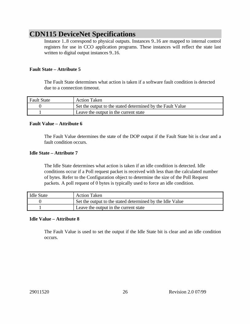
Instance 1..8 correspond to physical outputs. Instances 9..16 are mapped to internal controlregisters for use in CCO application programs. These instances will reflect the state lastwritten to digital output instances 9..16.
Fault State – Attribute 5
The Fault State determines what action is taken if a software fault condition is detecteddue to a connection timeout.
Fault State Action Taken 0 Set the output to the stated determined by the Fault Value 1 Leave the output in the current state
Fault Value – Attribute 6
The Fault Value determines the state of the DOP output if the Fault State bit is clear and afault condition occurs.
Idle State – Attribute 7
The Idle State determines what action is taken if an idle condition is detected. Idleconditions occur if a Poll request packet is received with less than the calculated numberof bytes. Refer to the Configuration object to determine the size of the Poll Requestpackets. A poll request of 0 bytes is typically used to force an idle condition.
Idle State Action Taken 0 Set the output to the stated determined by the Idle Value 1 Leave the output in the current state
Idle Value – Attribute 8
The Fault Value is used to set the output if the Idle State bit is clear and an idle conditionoccurs.

CDN115 DeviceNet Specifications
29011520 Revision 2.0 07/9927
Analog Input Point (AIP) Object Class Code: 10 (0x0A)
The Analog Input Point (AIP) Object models discrete analog inputs in a product. There is aseparate instance for each discrete input available on the device.
AIP Object Class Attributes
Attribute Access Name Type Value1 Get Revision UINT 12 Get Max Object Instance UINT 26 Get Max Class Identifier UINT 77 Get Max Instance Attribute UINT 8
AIP Object, Instance 1..2 Attributes
Attribute Access Name Type Value3 Get Value UINT 0..40957 Get Range USINT 2 == 0-10 Vdc8 Get Type USINT 6 == UINT
AIP Common Services
Service Code Class Instance Service Name16 (0x10) No Yes Set_Attribute_Single
AIP Object Attributes
Value - Attribute 3
Analog input value reflects the associated channel input value. The exact format of the inputis determined by the control words as defined in the Configuration Object.
Range – Attribute 7
The AIP Range value is fixed as type 2 (0-10 Vdc).
Type – Attribute 8
The AIP Type value is fixed as type 6 (UINT).
CDN115 DeviceNet Specifications
29011520 Revision 2.0 07/9928
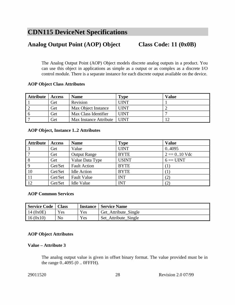
Analog Output Point (AOP) Object Class Code: 11 (0x0B)
The Analog Output Point (AOP) Object models discrete analog outputs in a product. Youcan use this object in applications as simple as a output or as complex as a discrete I/Ocontrol module. There is a separate instance for each discrete output available on the device.
AOP Object Class Attributes
Attribute Access Name Type Value1 Get Revision UINT 12 Get Max Object Instance UINT 26 Get Max Class Identifier UINT 77 Get Max Instance Attribute UINT 12
AOP Object, Instance 1..2 Attributes
Attribute Access Name Type Value3 Get Value UINT 0..40957 Get Output Range BYTE 2 == 0..10 Vdc8 Get Value Data Type USINT 6 == UINT9 Get/Set Fault Action BYTE (1)10 Get/Set Idle Action BYTE (1)11 Get/Set Fault Value INT (2)12 Get/Set Idle Value INT (2)
AOP Common Services
Service Code Class Instance Service Name14 (0x0E) Yes Yes Get_Attribute_Single16 (0x10) No Yes Set_Attribute_Single
AOP Object Attributes
Value – Attribute 3
The analog output value is given in offset binary format. The value provided must be inthe range 0..4095 (0 .. 0FFFH).

CDN115 DeviceNet Specifications
29011520 Revision 2.0 07/9929
Value Output voltage 0 -10 volts 800h (2048) 0 volts FFFh (4095) +10 volts
Range – Attribute 7 The analog output Range is fixed as 3 (-10 to +10 Vdc).
Type – Attribute 8
The analog output data type is fixed as 6 (UINT).
Fault State – Attribute 9
The Fault State determines what action is taken if a fault condition is detected. Faultconditions include software conditions (connection timeout).
Fault State Action Taken 0 Hold the last value 1 Set to low limit (-10 Vdc) 2 Set to high limit (+10 Vdc) 3 Set to value determined by Fault Value.
Idle State – Attribute 10
The Idle State determines what action is taken if an idle condition is detected. Idleconditions occur if a Poll request packet is received with less than the calculated numberof bytes. Refer to the Configuration object to determine the size of the Poll Requestpackets. A poll request of 0 bytes is typically used to force an idle condition.
Idle State Action Taken 0 Hold the last value 1 Set to low limit (-10 Vdc) 2 Set to high limit (+10 Vdc) 3 Set to value determined by Idle Value.
CDN115 DeviceNet Specifications
29011520 Revision 2.0 07/9930
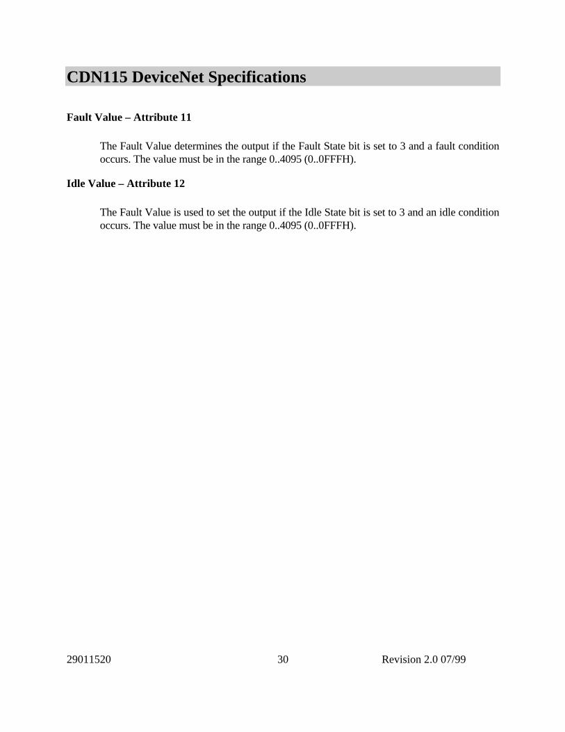
Fault Value – Attribute 11
The Fault Value determines the output if the Fault State bit is set to 3 and a fault conditionoccurs. The value must be in the range 0..4095 (0..0FFFH).
Idle Value – Attribute 12
The Fault Value is used to set the output if the Idle State bit is set to 3 and an idle conditionoccurs. The value must be in the range 0..4095 (0..0FFFH).

CDN115 DeviceNet Specifications
29011520 Revision 2.0 07/9931
Device Supervisor Object Class Code: 48 (0x30)
The Device Supervisor object provides summary information on the Device.
Device Supervisor Object Class Attributes
Attribute Access Name Type Value1 Get Revision UINT 12 Get Max Object Instance UINT 16 Get Max Class Identifier UINT 77 Get Max Instance Attribute UINT 16
Configuration Object, Instance 1 Attributes
Attribute Access Name Type Value3 Get Manufacturer Type SSTRING MIXED IO4 Get Semi Revision Level SSTRING E00-00005 Get Manufacturer Name SSTRING D.I.P. Inc.6 Get Manufacturer Model SSTRING CDN4947 Get Software Revision SSTRING XX.YYY (see below)8 Get Hardware Revision SSTRING XX.YYY (see below)11 Get Device Status USINT See Below12 Get Exception Status USINT15 Get/Set Alarm Enable BOOLEAN16 Get/Set Warning Enable BOOLEAN
Device Supervisor Object Common Services
Service Code Class Instance Service Name14 (0x0E) Yes Yes Get_Attribute_Single16 (0x10) No Yes Set_Attribute_Single
Device Supervisor Object Attributes
Manufacturer Model – Attribute 6
The Manufacturer Model string will be CDN494 based on the product code (see IdentityObject, Class 1, Instance 1, Attribute 3).

CDN115 DeviceNet Specifications
29011520 Revision 2.0 07/9932
Software Revision – Attribute 7
The Software Revision will be a text string of the Major and Minor revision information ofthe Identity object. It will have the format XX.YYY, where XX is the major revision andYYY is the Minor revision. The revision code will match that provided by the Identityobject.
Hardware Revision – Attribute 8
The Hardware Revision will be a text string reflecting the current revision of the hardware.It will have the format XX.YYY, where XX is the major revision and YYY is the Minorrevision.
Device Status – Attribute 9
The Device Status reflects the current state of the Device Supervisor object.
Attribute Value State 0 Undefined 1 Self Testing 2 Idle 3 Self-Test Exception 4 Executing 5 Abort 6 Critical Fault 7-50 Reserved – unused on CDN494 51-99 Device Specific – unused on CDN494 100-255 Vendor Specific – unused on CDN494
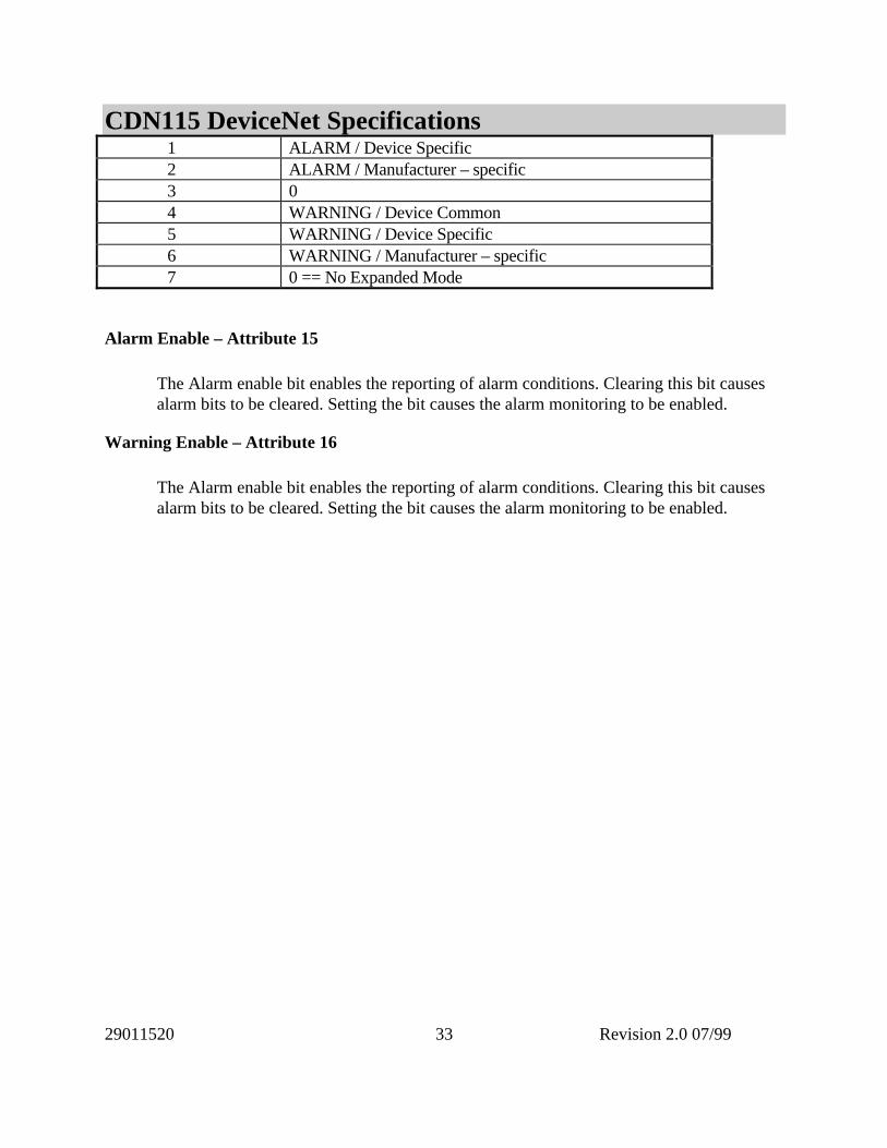
Exception Status – Attribute 12
The Exception status provides information on the current alarm and warning status of thedevice. This byte may be optionally reported as part of the Poll Response message. The byteprovides a summary of the state of the Exception and Alarm Detail attributes and has thefollowing interpretation.
Status Bit Function 0 ALARM / Device Common
CDN115 DeviceNet Specifications
29011520 Revision 2.0 07/9933
1 ALARM / Device Specific 2 ALARM / Manufacturer – specific 3 0 4 WARNING / Device Common 5 WARNING / Device Specific 6 WARNING / Manufacturer – specific 7 0 == No Expanded Mode
Alarm Enable – Attribute 15
The Alarm enable bit enables the reporting of alarm conditions. Clearing this bit causesalarm bits to be cleared. Setting the bit causes the alarm monitoring to be enabled.
Warning Enable – Attribute 16
The Alarm enable bit enables the reporting of alarm conditions. Clearing this bit causesalarm bits to be cleared. Setting the bit causes the alarm monitoring to be enabled.

CDN115 DeviceNet Specifications
29011520 Revision 2.0 07/9934
Configuration Object Class Code: 64 (0x40)
The CDN494 poll request/response packets are large. In some applications it may be desiredto reduce the packet size if not all the I/O channels are in use. The configuration object willadjust the poll request/response packet sizes. In addition, the configuration object givesaccess to several operational parameters such as power supply and temperature conditions.
Configuration Object Class Attributes
Attribute Access Name Type Value1 Get Revision UINT 12 Get Max Object Instance UINT 16 Get Max Class Identifier UINT 77 Get Max Instance Attribute UINT 9
Configuration Object, Instance 1 Attributes
Attribute Access Name Type Value1 Get/Set Mode USINT (1) Configuration mode2 Get/Set Num Digital Input USINT (1) Poll response count3 Get/Set Num Digital Output USINT (1) Poll request count4 Get/Set Num Analog Input USINT (1) Poll response count5 Get/Set Num Analog Output USINT (1) Poll request count
Configuration Object Common Services
Service Code Class Instance Service Name05 (0x05) No Yes Reset14 (0x0E) Yes Yes Get_Attribute_Single16 (0x10) No Yes Set_Attribute_Single
NOTE 1: Changing the configuration object will cause the CONSUMED and PRODUCEDsize of the POLL connection to be changed. These values are retained in E2 memory and mayonly be set when the POLL connection is not in the RUNNING state.
Configuration Reset Service
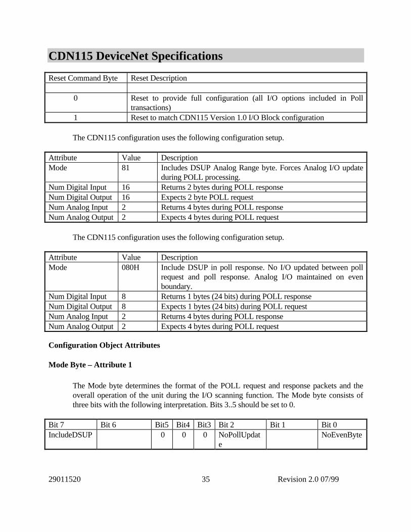
The Reset service causes the device configuration to return to a preset condition. The Resetservice accepts a single byte to determine the configuration desired following the resetcommand.
CDN115 DeviceNet Specifications
29011520 Revision 2.0 07/9935
Reset Command Byte Reset Description
0 Reset to provide full configuration (all I/O options included in Polltransactions)
1 Reset to match CDN115 Version 1.0 I/O Block configuration
The CDN115 configuration uses the following configuration setup.
Attribute Value DescriptionMode 81 Includes DSUP Analog Range byte. Forces Analog I/O update
during POLL processing.Num Digital Input 16 Returns 2 bytes during POLL responseNum Digital Output 16 Expects 2 byte POLL requestNum Analog Input 2 Returns 4 bytes during POLL responseNum Analog Output 2 Expects 4 bytes during POLL request
The CDN115 configuration uses the following configuration setup.
Attribute Value DescriptionMode 080H Include DSUP in poll response. No I/O updated between poll
request and poll response. Analog I/O maintained on evenboundary.
Num Digital Input 8 Returns 1 bytes (24 bits) during POLL responseNum Digital Output 8 Expects 1 bytes (24 bits) during POLL requestNum Analog Input 2 Returns 4 bytes during POLL responseNum Analog Output 2 Expects 4 bytes during POLL request
Configuration Object Attributes
Mode Byte – Attribute 1
The Mode byte determines the format of the POLL request and response packets and theoverall operation of the unit during the I/O scanning function. The Mode byte consists ofthree bits with the following interpretation. Bits 3..5 should be set to 0.
Bit 7 Bit 6 Bit5 Bit4 Bit3 Bit 2 Bit 1 Bit 0IncludeDSUP 0 0 0 NoPollUpdat
eNoEvenByte

CDN115 DeviceNet Specifications
29011520 Revision 2.0 07/9936
If the NoPollUpdate bit is set then the I/O is not updated between the POLL REQUEST andthe POLL RESPONSE operations. Analog and digital input data will reflect data collectedimmediately prior to the current Poll request. Analog and digital output data will be updatedafter the POLL RESPONSE is generated. Note that data aging is ~ 2 msec.
If the NoEvenByte bit is set then no padding bytes will be inserted or expected during thePOLL REQUEST and POLL RESPONSE processing. If this bit is cleared then the POLLREQUEST and POLL RESPONSE packets will be adjusted to ensure that the Analog I/Odata starts on an even byte boundary. Pad bytes will be eliminated in the Poll Request if theNum Analog Input is 0. Pad bytes will be eliminated in the Poll Response if the NumAnalog Output is 0.
If the IncludeDSUP bit is set the POLL response will include the Device Supervisor Statusinformation in the Poll response.
Num Digital Input – Attribute 2
The Num Digital Input attribute determines the number of input channels to be returned inthe POLL RESPONSE packet. The maximum number 16 bits. The number of poll responsebytes can be calculated as:
Number of bytes = ((number of channels) + 7) / 8
Num Digital Output – Attribute 3
The Num Digital Output attribute determines the number of output bytes to be processed inthe POLL REQUEST packet. The maximum number 16 bits. The number of poll responsebytes can be calculated as:
Number of bytes = ((number of channels) + 7) / 8
Num Analog Input – Attribute 4
The Num Analog Input attribute determines the number of analog input channels returnedin the POLL RESPONSE packet. The maximum number is 2. Each analog input produces 2bytes of data in the poll response packet. The number of bytes may be calculated as:
Number of bytes = ((number of channels) * 2)
Num Analog Output – Attribute 5

CDN115 DeviceNet Specifications
29011520 Revision 2.0 07/9937
The Num Analog Output attribute determines the number of analog output channels. Themaximum size is 2. Each analog output consumes two bytes of data in the poll requestpacket. The number of bytes may be calculated as:
Number of bytes = ((number of channels) * 2)
Poll Packet Sizes
The Poll Request and Response formats are determined by the configuration class attributes.
[DOUT(0..4)] [PAD(0..1)] [AOUT(0..16)]
DOUT will be either 0..2 bytes, determined by the Num Digital Output attribute.PAD will be either 0 or 1 byte. It is included to ensure that the AOUT arepositioned
on even byte boundaries if the MODE NoEvenByte attribute is cleared.AOUT will be 2 times the value set in the Num Analog Output attribute.
[DSUP] [DIN(0..4)] [PAD(0..1)] [AIN(0..16)]
DSUP will be 1 byte, determined by Mode IncludeDSUP bitDIN will be either 0..4 bytes, determined by the Num Digital Input attribute.PAD will be either 0 or 1 byte. It is included to ensure that the AIN are positioned
oneven byte boundaries if the MODE NoEvenByte attribute is cleared.
AIN will be 2 times the value set in the Num Analog Input attribute.
If the Num Digital Output and Num Analog Output are both 0 then the CONSUMED SIZEfor the POLL connection will be 0. In this case there is no POLL IDLE condition.