cdn.cnetcontent.comcdn.cnetcontent.com/f0/39/f039857d-2818-4342-aef2-5a683c75e12c.pdf · warning to...
TRANSCRIPT

DIGITAL BETACAM CAMCORDER
DVW-707/707PDVW-709WS/709WSPDVW-790WS/790WSP
OPERATION MANUAL [English]1st Edition (Revised 2)

WARNING
To prevent fire or shock hazard, do notexpose the unit to rain or moisture.
To avoid electrical shock, do not openthe cabinet. Refer servicing to qualifiedpersonnel only.
For the customers in the USAThis equipment has been tested and found to comply withthe limits for a Class B digital device, pursuant to Part 15of th e FCC Rules. These limits are designed to providereasonable protection against harmful interference in aresidential installation. This equipment generates, uses,and can radiate radio frequency energy and, if not installedand used in accordance with the instructions, may causeharmful interference to radio communications. However,there is no guarantee that interference will not occur in aparticular installation. If this equipment does causeharmful interference to radio or television reception, whichcan be determined by turning the equipment off and on,the user is encouraged to try to correct the interference byone or more of the following measures:
— Reorient or relocate the receiving antenna.— Increase the separation between the equipment and
receiver.— Connect the equipment into an outlet on a circuit
different from that to which the receiver is connected.— Consult the dealer or an experienced radio/TV
technician for help.

You are cautioned that any changes or modifications notexpressly approved in this manual could void yourauthority to operate this equipment.
The shielded interface cable recommended in this manualmust be used with this equipment in order to comply withthe limits for a digital device pursuant to Subpart B of Part15 of FCC Rules.
For the customers in the USA and Canada
RECYCLING NICKEL-CADMIUM BATTERIES
Nickel-Cadmium batteries are recyclable.You can help preserve our environmentby returning your unwanted batteries toyour nearest point for collection,recycling or proper disposal.Note: In some areas the disposal of nickel-cadmium
batteries in household or business trash may beprohibited.
RBRC(Rechargeable Battery Recycling Corporation)advises you about spent battery collection by the followingphone number.
Call toll free number: 1-800-822-8837 (United Statesand Canada only)
Caution: Do not handle damaged or leaking nickelcadmium batteries.

For the customers in EuropeThis product with the CE marking complies with the EMCDirective(89/336/EEC) issued by the Commission of theEuropean Community.Compliance with this directive implies conformity to thefollowing European standards:• EN55103-1: Electromagnetic Interference(Emission)• EN55103-2: Electromagnetic Susceptibility(Immunity)This product is intended for use in the followingElectromagnetic Environment(s):E1 (residential), E2 (commercial and light industrial), E3(urban outdoors) and E4 (controlled EMC environment, ex.TV studio)

Table of Contents 1
Table of Contents
Chapter 1 Overview1-1 Features ..................................................................................... 1-1
1-1-1 Camera Features .............................................................. 1-21-1-2 VTR Features .................................................................. 1-4
1-2 Example of System Configuration .......................................... 1-61-3 Precautions ................................................................................ 1-8
Chapter 2 Locations and Functions of Parts andControls
2-1 Power Supply ............................................................................ 2-12-2 Accessory Attachments ............................................................ 2-32-3 Audio Functions ........................................................................ 2-52-4 Shooting and Recording/Playback Functions ...................... 2-142-5 Setup Menu Operating Section ............................................. 2-272-6 Time Code System .................................................................. 2-292-7 Warnings and Indications ...................................................... 2-352-8 Warnings and Indications on the Display Panel .................. 2-38
Chapter 3 Recording and Playback3-1 About Cassettes ......................................................................... 3-1
3-1-1 Loading and Unloading a Cassette .................................. 3-13-1-2 Preventing Accidental Erasure ........................................ 3-4
3-2 Recording .................................................................................. 3-53-2-1 Basic Procedure ............................................................... 3-53-2-2 Continuous Recording ..................................................... 3-93-2-3 Starting a Shoot with a Few Seconds of Pre-Stored Picture
Data (Loop Rec Function) (When Using a BKDW-703Extension Board) ........................................................... 3-12
3-2-4 Reversing the picture orientation (vertically andhorizontally) (Using the BKDW-704 Extension Board)(DVW-709WS/709WSP/790WS/790WSP only) ......... 3-18
3-3 Checking the Recording — Playback ................................... 3-19

Table of Contents2
3-3-1 Checking the Last Two Seconds of the Recording— Recording Review .................................................... 3-19
3-3-2 Checking the Recording on the Color Video Monitor— Playback in Color ..................................................... 3-20
Chapter 4 Adjustments and Settings forRecording
4-1 Adjusting the Black Balance and the White Balance ............ 4-14-1-1 Adjusting the Black Balance ........................................... 4-24-1-2 Adjusting the White Balance .......................................... 4-5
4-2 Setting the Electronic Shutter ............................................... 4-134-2-1 Shutter Modes ............................................................... 4-134-2-2 Selecting the Shutter Mode and Speed .......................... 4-15
4-3 Changing the Reference Value for Automatic Iris Adjustment.................................................................................................. 4-21
4-4 Adjusting the Audio Level ..................................................... 4-244-5 Setting the Time Data ............................................................. 4-27
4-5-1 Setting the User Bits ...................................................... 4-274-5-2 Setting the Time Code ................................................... 4-294-5-3 Saving the Real Time in the Time Code ....................... 4-314-5-4 Synchronizing the Time Code ....................................... 4-324-5-5 Setting Cassette Numbers and Shot Numbers ............... 4-37
4-6 Setup Menu Display on the Viewfinder Screen ................... 4-394-6-1 Setup Menu Configuration ............................................ 4-394-6-2 Basic Use of the Setup Menu ........................................ 4-43
4-7 Indicators in the Viewfinder .................................................. 4-484-7-1 Layout of Indicators in the Viewfinder ......................... 4-484-7-2 Setting the Indicator ................................................. 4-50
4-8 Status Display on the Viewfinder Screen ............................. 4-534-8-1 Layout of the Status Display on the Viewfinder Screen4-544-8-2 Selecting the Display Items ........................................... 4-584-8-3 Display Mode and Setting Change and Adjustment Progress
Messages ....................................................................... 4-61

Table of Contents 3
4-8-4 Setting the Marker Display ........................................... 4-644-8-5 Recording Superimposed Shot Data in Color Bars ....... 4-664-8-6 Setting the Shot ID ........................................................ 4-694-8-7 Displaying Time Code and Other Information ............. 4-73
4-9 Adjustments and Settings From the Setup Menu ................ 4-764-9-1 Setting the GAIN Selector Values ................................ 4-774-9-2 Selecting the Functions ................................................. 4-794-9-3 Selecting the Test Output .............................................. 4-834-9-4 Selecting the Aspect Ratio (DVW-709WS/709WSP/
790WS/790WSP Only) ................................................. 4-854-9-5 Setting the color temperature manually ........................ 4-914-9-6 Specifying an offset for the auto white balance setting 4-934-9-7 Setting the CAMERAMAN menu ................................ 4-95
4-10 VTR Menu Display in the Display Panel .............................. 4-994-10-1 Configuration and Functions of the VTR Menu ........... 4-994-10-2 Using the VTR Menu .................................................. 4-1004-10-3 Example Operations in the VTR Menu ....................... 4-106
4-11 Using the Setup Card ........................................................... 4-1134-11-1 Handling the Setup Card ............................................. 4-1134-11-2 Using Data on the Setup Card ..................................... 4-115
Chapter 5 Setting Up the Camcorder5-1 Power Supply ............................................................................ 5-1
5-1-1 Using a BP-L60A/L90A Battery Pack ............................ 5-15-1-2 Using an NP-1B Battery Pack ......................................... 5-45-1-3 Using a BP-90A Battery Pack ......................................... 5-55-1-4 Avoiding Breaks in Operation Due to Dead Batteries .... 5-75-1-5 Using an AC Adaptor ...................................................... 5-85-1-6 Using the Anton Bauer Ultralight System ...................... 5-95-1-7 Using the Anton Bauer Intelligent Battery System ......... 5-9
5-2 Adjusting the Viewfinder ....................................................... 5-105-2-1 Adjusting the Viewfinder Position ................................ 5-105-2-2 Adjusting the Viewfinder Focus and Screen ................. 5-12

Table of Contents4
5-2-3 Detaching the Viewfinder ............................................. 5-135-2-4 Detaching the Eyepiece ................................................. 5-15
5-3 Mounting the Lens .................................................................. 5-175-4 Adjusting the Flange Focal Length ....................................... 5-185-5 Audio Input System ................................................................ 5-20
5-5-1 Using the Supplied Microphone .................................... 5-205-5-2 Using an External Microphone ..................................... 5-235-5-3 Attaching a UHF Portable Tuner (for a UHF Wireless
Microphone System) ..................................................... 5-285-5-4 Connecting Line Input Audio Equipment ..................... 5-33
5-6 Tripod Mounting .................................................................... 5-345-7 Attaching the Shoulder Strap ................................................ 5-365-8 Adjusting the Shoulder Pad Position .................................... 5-385-9 Putting On the Rain Cover .................................................... 5-395-10 Connecting the Remote Control Unit ................................... 5-42
Chapter 6 Maintenance6-1 Testing the Camcorder Before Shooting ................................ 6-1
6-1-1 Preparations for Testing .................................................. 6-16-1-2 Testing the Camera ......................................................... 6-36-1-3 Testing the VTR .............................................................. 6-6
6-2 Maintenance ............................................................................ 6-106-2-1 Cleaning the Video Heads ............................................. 6-106-2-2 Cleaning the Viewfinder ............................................... 6-10
6-3 Operation Warnings ............................................................... 6-12
AppendixSpecifications ..................................................................................... A-1
Video Camera Section ............................................................... A-2VTR Section .............................................................................. A-5Supplied Accessories ................................................................. A-8Recommended Additional Equipment ...................................... A-8
Glossary ............................................................................................ A-11Index .................................................................................................... I-1
Chapter 1 Overview 1-1
1
Overview
1-1 FeaturesThe DVW-707/707P series 1) Digital Camcorder combines a color videocamera, which uses IT 2) type Power HADTM 3) sensor CCDs 4), with aDigital BETACAM series portable videocassette recorder. Its excellentimage quality, sensitivity, portability, and dust- and water-proofconstruction make it ideal as a camcorder for ENG 5) and EFP 6) in thesame way the earlier DVW-700/700P. The introduction of a new methodof processing digital signals improves the image quality even further andmakes the camcorder far easier to use.The DVW-790WS/790WSP employs FIT 7) type Power HAD sensorCCDs featuring a lower smear level and the ability to switch between theconventional aspect ratio of 4:3 and a wide screen aspect ratio of 16:9.The DVW-709WS/709WSP is identical with the DVW-790WS/790WSPexcept for its use of IT type Power HAD sensor CCDs and its lack of anECS (extended clear scan) mode.
....................................................................................................................................1) The DVW-707/709WS/790WS is for the NTSC broadcast system. The DVW-
707P/709WSP/790WSP is for the PAL broadcast system. The descriptions givenin this manual apply to both models, any differences being clearly noted in thetext.
2) IT: Interline Transfer3) Power HAD: Power Hole-Accumulated Diode
“Power HAD” is a registered trademark of Sony Corporation.4) CCD: Charge-Coupled Device5) ENG: Electronic News Gathering6) EFP: Electronic Field Production7) FIT: Frame Interline Transfer

Chapter 1 Overview1-2
1 1-1-1 Camera FeaturesThe features of the DVW-707/707P/709WS/709WSP/790WS/790WSPseries camera are described below.• Power HAD sensor CCDs ensure high sensitivity and high image
quality.• The 12 bit AD converter has improved picture quality, stability, and
reliability.• A setup menu enables you to control features such as status displays,
messages, and markers; to select values or functions; and to operate asetup card.
• The settable items in the CAMERAMAN menu allow you to createyour own custom menu.
• A setup card (not supplied) makes it easy to replicate the recorder setupdata appropriate to the shooting conditions, and ensures uniformshooting 1).
• Use of a built-in sophisticated electronic shutter, which has selectablemodes, Clear ScanTM 2), Extended Clear Scan (for DVW-790WS/790WSP only) and Super Enhanced Vertical Definition, ensuresshooting with little or no blurring.
• Selectable video gain ensures a noise-free image.• A simple switch operation enables automatic adjustment of the black
set, black balance, and white balance. Memory functions make it easyto replicate the settings appropriate for the lighting conditions.
• The ATW 3) function automatically adjusts the white balance for thevarying lighting conditions during shooting.
....................................................................................................................................1) The data saved in the setup card for the DVW-707/707P/709WS/709WSP/
790WS/790WSP is not interchangeable with the data saved in setup cards forother camcorders.
2) Clear Scan: “Clear Scan” is a trademark of Sony Corporation.3) ATW: Auto Tracing White balance

Chapter 1 Overview 1-3
1
....................................................................................................................................1) “TruEye”: TruEye is a trademark of Sony Corporation.2) SNG: Satellite News Gathering
• The “TruEyeTM” 1) process is used to ensure naturally colored pictureseven when shooting very bright subjects.
• The video gain can be boosted to 48dB instantly using the TURBOGAIN button (factory setting: 42dB).
• A high-performance viewfinder is adjustable forward, backward andsideways, and has full auxiliary equipment.
• Character display functions on the viewfinder indicate switch settings,black and white balance adjustment, and warnings.
• Warning indicators and sound inform you of VTR faults, end of tape,low battery, etc.
• The camcorder is provided with a filter disk for adjusting the filtersetting to the shooting conditions.
• Fine adjustment of the reference value for automatic iris control isprovided.
• A built-in circuit produces a SMPTE type color bar signal for easyadjustment of the color monitor. An SNG 2) bar signal is also providedfor SNG uplink purposes.
• A super-cardioid directional microphone with an external power supplysystem is supplied. Other types of microphones can also be connected.
• By connecting the BVF-VC10W Color Viewfinder (not supplied), youcan check both the camera image and a playback image in color.
• The RM-B150 Remote Control Unit (8 pin, not supplied) controlssome of the camera functions and the VTR functions. You can use theRM-P9 (6 pin, not supplied) by connecting it through the CCA-86-0.4conversion cable (not supplied).
• By connecting the CA-701 Camera Adaptor (not supplied), you caninput CH-3 and CH-4 audio signals and output SDI signals.
• By connecting the CA-702 Camera Adaptor (not supplied), thecamcorder can be connected to a portable VTR with a CCZ (26 pin)cable, allowing you to record external analog video signals or serialdigital interface (SDI) signals (including an embedded audio signal).

Chapter 1 Overview1-4
1 • You can add extra functions to the camcorder by attaching thefollowing extension boards (not supplied).
BKDW-702: This board allows you to output an SDI signal(corresponding to EDH 1)) from the VIDEO OUT connector. Thesetup menu is used to select either composite video signal outputor SDI signal output.
BKDW-704: When a cinema lens is attached to the camcorder, thisboard allows you to reverse the picture orientation (vertically andhorizontally) through a setup menu operation (DVW-709WS/709WSP/790WS/790WSP only).
1-1-2 VTR FeaturesThe VTR features of this camcorder are described below.• Digital BETACAM format gives improved signal-to-noise ratio,
frequency bandwidth, waveform characteristics, and detail playbackcharacteristics to ensure higher video and audio quality.
• The shooting date and time, camera ID, cassette number and otherinformation can be recorded on the tape as shot data.
• It is possible to record recording start markers and good shot markerson the tape while shooting, and search automatically for required cutswhen editing.
• It is possible to automatically rewind and review the last few secondsof the recording on the tape for a quick check immediately aftershooting.
• No playback adaptor is needed to see the color playback image.• The five times normal speed search function provides quick positioning
of the tape.
....................................................................................................................................1) EDH: Error Detection and Handling

Chapter 1 Overview 1-5
1• Both LTC 1) and VITC 2) recordings can be made, as can LTCplayback.
• The built-in time code generator is synchronized with an externalgenerator.
• A lithium battery is the back-up power supply for the time codegenerator enabling the time code to be held for about 5 years withoutcharging the camcorder power supply.
• Optional long-life battery packs are available.• Pressing the VTR START button on the camcorder or the VTR button
on the lens ensures recording continuity from the very next frame.• By connecting the VA-DN1 Camcorder Interface Adaptor (not
supplied) to the 8-pin REMOTE connector, you can control some ofthe VTR functions from a 9-pin remote control device. (A CCA-86-0.4 conversion cable is needed for the connection.)
• The time code is displayed in the LCD window screen even when thepower is off. Automatic power shut-off function with five time codeindication settings.
• This board continuously stores a few seconds of the most recent picturedata. Recording is started with this data when the REC button ispressed to prevent the loss of picture data (Loop Rec function) (whenthe BKDW-703 is attached).
....................................................................................................................................1) LTC: Longitudinal Time Code2) VITC: Vertical Interval Time Code

Chapter 1 Overview1-6
1
a) For more information, see “Viewfinder andrelated equipment” (page A8).
Video monitor
Field pickup unit
Video monitor
Color image checkwhile shootingColor playback
Video monitor
BKW-401 ViewfinderRotation Bracket
BVF-VC10WColor Viewfinder
VA-DN1 CamcorderInterface Adaptor
RM-B150/RM-P9 b)
Remote Control Unit
BSC-1Setup Card
BVR-3Remote Control Unit
Fog-proof filter(Part No.1-547-341-11)
CA-701/702/702P/755/755PCamera Adaptor
1-2 Example of SystemConfiguration
The diagram below shows a typical configuration of the camcorder for ENG and EFP.For more information about connections of the additional equipment and accessories,see Chapter 5, as well as the operation manuals for the connected equipment.
BKDW-702 for outputting an SDI signalBKDW-703 for Loop Rec functionBKDW-704 for reversing the pictureorientation (DVW-709WS/709WSP/790WS/790WSP only)
ExtensionBoard
b) A CCA-86-0.4 conversion cable (not supplied) is required for connecting the RM-P9 and VA-DN1.
Servo Filter UnitBKDW-701

Chapter 1 Overview 1-7
1
Lens assembly a)(−2.8 D to +2.0 D)(Part No. A-8262-537-A)Lens assembly a)(−3.6 D to −0.8 D)(Part No. A-8262-538-A)Lens assembly a)(−3.6 D to +0.4 D)(Part No. A-8267-737-A)Lens assembly a)
(3 × magnification)(−2.4 D to +0.5 D)(Part No. A-8314-798-A)
External microphone C-74, etc.
CAC-12 Microphone Holder
Audio equipment
WRR-28H/28M/28L/810A/ 860AUHF Portable Tuner
CCXA-53 Audio Cable
Sound signal equipment
Power source
ACpower c)
Battery
DC-L1Battery Adaptor
NP-1BBattery Pack
AC-DN1/DN2AAC Adaptor
AC-550/550CEAC Adaptor
c) 120 V AC or220 to 240V AC
BC-1WD/1WDCEBattery Charger
BC-210/210CE/410/410CEBattery Charger
DC-L90Battery Adaptor
BP-L60A/L90ABattery Pack
BC-L100/L100CE BatteryCharger
BP-90ABattery Pack

Chapter 1 Overview1-8
1
1-3 PrecautionsUse and Storage
Do not subject the camcorder to severe shocksThe internal mechanism may be damaged or the body warped.
After useAlways turn off the power.
Before storing the camcorder for a long periodRemove the battery pack.
Use and storage locationsStore in a ventilated place. Avoid using or storing the camcorder in thefollowing places.• Places subject to temperature extremes• Damp places• Places subject to severe vibration• Near strong magnetic fields• In direct sunlight or close to heaters for extended periods
Chapter 2 Locations and Functions of Parts and Controls 2-1
2
Locations and Functions of P
arts and Controls
2-1 Power Supply
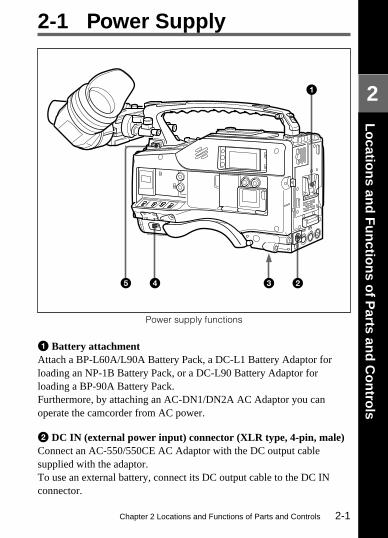
Power supply functions
1 Battery attachmentAttach a BP-L60A/L90A Battery Pack, a DC-L1 Battery Adaptor forloading an NP-1B Battery Pack, or a DC-L90 Battery Adaptor forloading a BP-90A Battery Pack.Furthermore, by attaching an AC-DN1/DN2A AC Adaptor you canoperate the camcorder from AC power.
2 DC IN (external power input) connector (XLR type, 4-pin, male)Connect an AC-550/550CE AC Adaptor with the DC output cablesupplied with the adaptor.To use an external battery, connect its DC output cable to the DC INconnector.
45 2
1
3

Chapter 2 Locations and Functions of Parts and Controls2-2
2
3 BREAKER buttonExcessive current in the internal circuitry, whatever the cause, will tripthe internal circuit breaker, automatically cutting off the power. If thebreaker trips, consult your Sony service personnel.
4 POWER switchThis switch turns the main power supply on and off.
5 LIGHT switchThis selects the way in which a video light connected to the LIGHTconnector is switched on and off.AUTO: When the video light switch is turned on, starting recording with
the VTR turns on the light.MANUAL: The video light switch controls the light, turning it on and
off manually.

Chapter 2 Locations and Functions of Parts and Controls 2-3
2
Lens cable clamps
2-2 Accessory Attachments
Accessory attachments
1 Shoulder strap postsAttach the supplied shoulder strap to these posts.
2 Light shoeAttach a video light, etc. to this shoe.
6
4
3
5
9
8
7
1 2
Chapter 2 Locations and Functions of Parts and Controls2-4
2
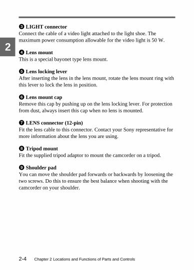
3 LIGHT connectorConnect the cable of a video light attached to the light shoe. Themaximum power consumption allowable for the video light is 50 W.
4 Lens mountThis is a special bayonet type lens mount.
5 Lens locking leverAfter inserting the lens in the lens mount, rotate the lens mount ring withthis lever to lock the lens in position.
6 Lens mount capRemove this cap by pushing up on the lens locking lever. For protectionfrom dust, always insert this cap when no lens is mounted.
7 LENS connector (12-pin)Fit the lens cable to this connector. Contact your Sony representative formore information about the lens you are using.
8 Tripod mountFit the supplied tripod adaptor to mount the camcorder on a tripod.
9 Shoulder padYou can move the shoulder pad forwards or backwards by loosening thetwo screws. Do this to ensure the best balance when shooting with thecamcorder on your shoulder.

Chapter 2 Locations and Functions of Parts and Controls 2-5
2
2-3 Audio Functions
Audio functions (1)
1 MicrophoneThis is a super-cardioid directional microphone with an external powersupply system. You can use it as an interview microphone by connectingit to an extension cable (not supplied).
2 MIC IN (microphone input) connector (XLR type, 3-pin, female)The supplied microphone connects to this connector. By using anextension cable (not supplied), you can connect a microphone other thanthe supplied one as long as it is provided with an external power supplysystem. The connector supplies power (+48 V) to the microphone.
1
2
3

Chapter 2 Locations and Functions of Parts and Controls2-6
2
3 MIC (microphone) AUDIO LEVEL controlIf one or both of the AUDIO IN switches are set to FRONT, you canadjust the recording level of the microphone.When AUDIO is set to ON in the VF DISP 2/2 page of the setup menu,the viewfinder DISPLAY switch is set to ON, MONITOR switch is setto CH1, you can adjust the channel-1 audio level while watching theindication in the viewfinder.
Chapter 2 Locations and Functions of Parts and Controls 2-7
2
Audio functions (2)
4
5
6
8
0
9
7
ADVANCE
PRESET
F-RUNSET
DIAG
R-RUN
DATADISPLAY
NDFDF
REGEN
CLOCK
AUDIO INAUDIO SELECT
REAR
MIXCH-1 CH-2
FRONT
SHIFT
MANUALAUTO
LEVELCH-1••
••
•
• •
••
•
•
0 10
CH-2••
••
•
• •
••
•
•
CUE IN
0 10
U-BITSHOT TIME
NO.
Illustration: DVW-707/709WS/790WS (for the NTSC broadcast system)

Chapter 2 Locations and Functions of Parts and Controls2-8
2
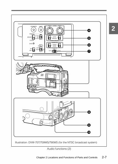
4 AUDIO LEVEL CH-1/CH-2 (audio channel 1 and channel 2recording level) controls
These controls adjust the audio level of channels 1 and 2 when you setthe AUDIO SELECT CH-1/CH-2 switches to MANUAL.
5 AUDIO SELECT CH-1/CH-2 (audio channel-1 and channel-2select) switches
These switches set the audio level adjustment for channels 1 and 2 toMANUAL or AUTO.AUTO: Select this setting for automatic adjustment.MANUAL: Select this setting for manual adjustment.
6 AUDIO IN (audio input) switchesThese switches select the audio input signals for audio channels 1 and 2.The input signal source is one of:FRONT: The input signal source is the MIC IN connector.REAR: The input signal source is the AUDIO IN CH-1/CH-2
connectors.The audio input signals from the MIC IN connector are always recordedon audio channels 3 and 4, respectively, whether or not they are recordedon audio channels 1 and 2 in accordance with the setting of this switch.With the CA-701 (not supplied) connected to the camcorder, you canrecord separate sounds to audio channels 3 and 4.For more information, refer to “maintenance manual.”
7 CUE IN (cue track input) switchThis switch selects the input signals for recording the cue track.CH-1 : Channel 1 input signalMIX : Mixed input signal of channels 1 and 2CH-2 : Channel 2 input signal

Chapter 2 Locations and Functions of Parts and Controls 2-9
2
8 AUDIO OUT (audio output) connector (XLR type, 5-pin, male)This connector outputs the stereo sound.Using a CCXA-53 Audio Cable (not supplied), you can convert from a5-pin connection to two 3-pin connections.
9 AUDIO IN CH-1/CH-2 (audio channel 1 and channel 2 input)connectors (XLR type, 3-pin, female) and LINE/MIC/+48 V ON(line input/microphone input/external power supply +48 V on)selectors
These are the audio input connectors for channels 1 and 2, to which youcan connect a microphone or other audio sources.The LINE/MIC/+48 V ON selectors select the audio input signal sourceconnected to these connectors, as follows:LINE: Line input from an audio componentMIC: A microphone with internal batteries+48 V ON: A microphone with an external power supply system
q; DC OUT (DC power output) connectorThis connector supplies power for a WRR-28H/28M/28L/810/860AUHF Portable Tuner (not supplied).Alternatively, it can supply power for a BVR-3 Remote Control Unitcombined with a VA-DN1 Camcorder Interface Adaptor.
Note
The type of UHF portable tuner which can be connected depends on thecountry where the camcorder is used.For more information, consult your Sony representative.

Chapter 2 Locations and Functions of Parts and Controls2-10
2
Audio functions (3)
qa ALARM volume controlThis control adjusts the speaker or earphone alarm volume. At theminimum position, no sound can be heard.You can adjust the internal volume control so that the alarm is audibleeven at the minimum setting of the ALARM volume control.For more information, refer to “maintenance manual.”
qd qaqs

Chapter 2 Locations and Functions of Parts and Controls 2-11
2
Minimum Maximum
ALARM volume control
qs MONITOR volume controlThis control adjusts the speaker or earphone sound volume, excludingthe alarm sound. At the minimum position, no sound can be heard.
MONITOR volume control
MONITORCH-1MIXCH-2
Minimum Maximum

Chapter 2 Locations and Functions of Parts and Controls2-12
2
qd MONITOR (audio channels select) switchThis switch selects the audio output to the speaker or earphone. Theaudio level indication in the viewfinder screen switches automaticallyaccording to the selection.CH-1: Audio channel 1MIX: Mixed sound of channels 1 and 2CH-2: Audio channel 2
Audio functions (4)
qf
qg
Chapter 2 Locations and Functions of Parts and Controls 2-13
2
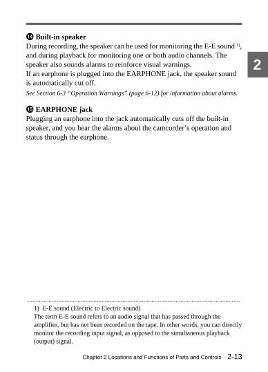
qf Built-in speakerDuring recording, the speaker can be used for monitoring the E-E sound 1),and during playback for monitoring one or both audio channels. Thespeaker also sounds alarms to reinforce visual warnings.If an earphone is plugged into the EARPHONE jack, the speaker soundis automatically cut off.See Section 6-3 “Operation Warnings” (page 6-12) for information about alarms.
qg EARPHONE jackPlugging an earphone into the jack automatically cuts off the built-inspeaker, and you hear the alarms about the camcorder’s operation andstatus through the earphone.
....................................................................................................................................1) E-E sound (Electric to Electric sound)The term E-E sound refers to an audio signal that has passed through theamplifier, but has not been recorded on the tape. In other words, you can directlymonitor the recording input signal, as opposed to the simultaneous playback(output) signal.

Chapter 2 Locations and Functions of Parts and Controls2-14
2Eyecup
2-4 Shooting and Recording/Playback Functions
Shooting and recording/playback functions (1)
16
7
8
9
0
5
4
2
3

Chapter 2 Locations and Functions of Parts and Controls 2-15
2
1 ViewfinderThe viewfinder lets you view the camera image in black and white whileshooting the picture and also see the playback picture from the VTR. Italso displays various warnings and other information, a zebra pattern 1),safety zone marker 2), and center marker 3).
2 BRIGHT (brightness) controlThis control adjusts the picture brightness on the viewfinder screen. Ithas no effect on the camera output signal.
3 CONTRAST controlThis control adjusts the picture contrast on the viewfinder screen. It hasno effect on the camera output signal.
4 PEAKING controlThis control adjusts the sharpness of the picture on the viewfinder screento make focusing easier. It has no effect on the camera output signal.
....................................................................................................................................1) Zebra pattern
The zebra pattern aids in manual iris adjustment by indicating areas of thepicture where the video level is approximately 70% IRE (for the DVW-707/709WS/790WS) or 490 mV (for the DVW-707P/709WSP/790WSP).
2) Safety zone markerThe safety zone marker is a rectangle indicating the effective picture area whichis equivalent to 80%, 90% (the factory setting) or 100% of the entire viewfinderscreen area. A setup menu lets you change the effective picture area from 90%to 80% or 100%.
For more information, see Section 4-8-4 “Setting the Marker Display” (page4-64).
3) Center markerThe center marker indicates the center of the picture with a crosshair.

Chapter 2 Locations and Functions of Parts and Controls2-16
2
5 ZEBRA (zebra pattern) switchThis switch controls the zebra pattern on the viewfinder screen.ON: The zebra pattern is displayed and stays.OFF: No zebra pattern is displayed.MOMENT: The zebra pattern is displayed and stays for a few seconds.
The zebra pattern display is factory set to indicate picture areaswhere the video level is approximately 70 IRE (for the DVW-707/709WS/790WS) or 490 mV (for the DVW-707P/709WSP/790WSP).It is possible to display an additional pattern, indicating areas of 100IRE (for the DVW-707/709WS/790WS) and above, or 700 mV (forthe DVW-707P/709WSP/790WSP) and above. The video levels tobe indicated with these patterns can be changed.
For more information, refer to “maintenance manual.”
6 Diopter adjustment ringUse this ring to adjust the viewfinder image for your vision.
7 Viewfinder left-right positioning ringUse this ring to move the viewfinder sideways.
8 Viewfinder front-rear positioning leverUse this lever to move the viewfinder forward or backward.
9 Cameraman tally indicatorThis indicator lights while the camcorder is operating.Slide the window open when you shoot, keeping your eye away from theviewfinder.
0 Viewfinder stopperPull this stopper up to detach the viewfinder from the camera.

Chapter 2 Locations and Functions of Parts and Controls 2-17
2
Shooting and record/playback functions (2)
qj
qk
qh
qa
qdqfqg
qs w; ql
Chapter 2 Locations and Functions of Parts and Controls2-18
2
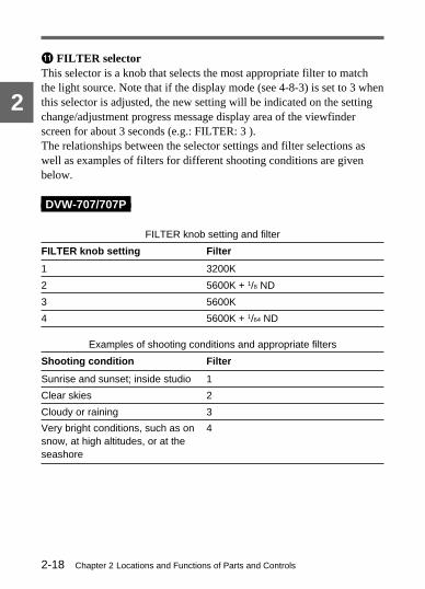
qa FILTER selectorThis selector is a knob that selects the most appropriate filter to matchthe light source. Note that if the display mode (see 4-8-3) is set to 3 whenthis selector is adjusted, the new setting will be indicated on the settingchange/adjustment progress message display area of the viewfinderscreen for about 3 seconds (e.g.: FILTER: 3 ).The relationships between the selector settings and filter selections aswell as examples of filters for different shooting conditions are givenbelow.
DVW-707/707P
FILTER knob setting and filter
FILTER knob setting Filter
1 3200K
2 5600K + 1/8 ND
3 5600K
4 5600K + 1/64 ND
Examples of shooting conditions and appropriate filters
Shooting condition Filter
Sunrise and sunset; inside studio 1
Clear skies 2
Cloudy or raining 3
Very bright conditions, such as onsnow, at high altitudes, or at theseashore
4

Chapter 2 Locations and Functions of Parts and Controls 2-19
2
DVW-709WS/709WSP/790WS/790WSP
FILTER knob (outer) setting and CC filter types
FILTER knob (outer) setting CC filter selection
A1) Cross filter 2)
B 3200K
C 4300 K
D 6300K
FILTER (Inner knob) setting and ND filter
FILTER knob (inner) setting ND filter
1 1) Straight through
2 1/4 ND
3 1/16 ND
4 1/64 ND
Examples of shooting conditions and appropriate filters
Shooting condition CC filter ND filter
Sunrise and sunset;inside studio
B 1
Clear skies C or D 2 or 3
Cloudy or raining D 1 or 2
Very bright conditions,such as on snow, athigh altitudes, or at theseashore
C or D 3 or 4
....................................................................................................................................1) The filter for FILTER settings A and 1 are fixed and cannot be changed.2) Cross filter
This is a special effects filter which generates a cross-hair light pattern inhighlighted portions.

Chapter 2 Locations and Functions of Parts and Controls2-20
2
qs TURBO GAIN buttonWhen shooting under extremely poor lighting conditions, press thebutton once to boost the video gain to the value preset with the menu (upto 48dB, factory setting: 42dB). To stop boosting the gain, press thebutton once more or use the GAIN switch.
qd WHITE BAL (white balance memory) switchThis switch determines the source of white balance settings.PRST (preset): Adjusts the color temperature corresponding to the
position of the filter ring.A or B: When the AUTO W/B BAL switch is pushed to WHT, the white
balance is automatically adjusted according to the current position ofthe filter ring, and the adjusted value is stored in either memory A ormemory B. (There are two memories for each filter, so a total ofeight adjustments can be stored.) When the two-part FILTERselector is in the same position as at when the WHITE BAL switchwas adjusted, the stored value is called from memory, and thecamcorder automatically adjusts itself to that value.
B (ATW): When this switch is set to B whereas, in the setup menuOPERATION 1 page, B is set to ATW 1), the ATW is activated.You can use the AUTO W/B BAL switch even when the ATW is inuse.
Note that if the display mode (see 4-8-3) is set to 3 when this switch isadjusted, the new setting will be indicated on the setting change/adjustment progress message display area of the viewfinder screen forabout 3 seconds (e.g. WHITE : A CH).
....................................................................................................................................1) ATW (Auto Tracing White balance)
The white balance of the picture being shot is adjusted automatically for thevarying lighting conditions.

Chapter 2 Locations and Functions of Parts and Controls 2-21
2
qf OUTPUT/DCC (output signal/dynamic contrast control) selectorThis selector switches the video signal that is output to the VTR,viewfinder, and video monitor, between the color bar signal and thecamera output. It also switches DCC 1) on and off when output from thecamera is selected.
OUTPUT/DCC selector
CAM, DCC ONThe video signal from the camera is outputand the DCC circuit operates.
CAM, DCC OFFThe video signal from the camera is outputand the DCC circuit does not operate.
BARS, DCC OFFAn SMPTE type or EBU type color barsignal is output and the DCC circuit doesnot operate. For example, use the settingfor the following purposes.• Adjusting the video monitor• Recording the color bar signal
....................................................................................................................................1) DCC (Dynamic Contrast Control)
Against a very bright background with the iris opening adjusted to the subject,objects in the background will be lost in the glare. The DCC function willrestore much of the lost detail and is particularly effective in the following cases.• Shooting a subject against a bright sky• Shooting a subject indoors, against a background through a window• Any high contrast scenes
•OFF
BARS•
CAM•
•ON
DCC
OU
TP
UT

Chapter 2 Locations and Functions of Parts and Controls2-22
2
qg GAIN selectorThis selector switches the gain of the video amplifier to match thelighting conditions during shooting. The gains corresponding to the L,M, and H settings are selected from the setup menu before use. Thefactory settings are L = 0 dB, M = 9 dB, and H = 18 dB.Note that if the display mode (see 4-8-3) is set to 3 when this selector isadjusted, the new setting will be indicated on the setting change/adjustment progress message display area of the viewfinder screen forabout 3 seconds (e.g. GAIN: 12 dB).For information about setting the gain values, see Section 4-9-1 “Setting the GAINSelector Values” (page 4-77).
qh AUTO W/B BAL (automatic white/black balance adjustment)switch
This switch activates the adjustment functions of the white balance andblack balance.WHT: Automatic adjustment of the white balance. If the WHITE BAL
switch is set to A or B, the white balance setting is stored in thecorresponding memory. When the ATW setting is selected in thesetup menu, the white balance setting adjusted with this switch is notstored in memory. The Auto White balance is deactivated while theWHITE BAL switch is set to PRST.
BLK: Automatic adjustment of the black set and the black balance. Thesetting is stored in a separate memory.
qj SHUTTER selectorSet this selector to ON to use the electronic shutter. Set it to SEL toswitch the shutter speed or mode setting within the range that has beenpreviously set from the setup menu.Note that if the display mode (see 4-8-3) is set to 2 or 3 when thisselector is adjusted, the new setting will be indicated on the settingchange/adjustment progress message display area of the viewfinderscreen for about 3 seconds (e.g.:SS: 1/250 or :CLS: 60.6 Hz).

Chapter 2 Locations and Functions of Parts and Controls 2-23
2
For more information about the shutter speed and mode settings, see Section 4-2“Setting the Electronic Shutter” (page 4-13).
qk REMOTE (remote control) connector (8-pin)Connect the RM-B150 remote control unit (not supplied) to thisconnector.Connect the RM-P9 Remote Control Unit (not supplied) with conversioncable or VA-DN1 Camcorder Interface Adaptor (not supplied) to thisconnector.By connecting a camcorder interface adaptor, you can control the VTRfrom a 9-pin remote control device.
Note
If the REMOTE and TEST OUT connectors are used at the same time, itmay not be possible to generate video signals at standard levels.
ql VIDEO OUT (video output) connector (BNC type)This connector outputs a composite signal (standard level, 75-ohmterminated) to the video monitor. If the video monitor is connected here,you can monitor the picture being shot by the camcorder as well as thepicture recorded by the VTR. When synchronizing the time code of anexternal VTR with that of the camcorder, connect this connector to thevideo input connector of the external VTR.By attaching the BKDW-702 extension board (not supplied), you canoutput an SDI signal (corresponding to EDH) from the VIDEO OUTconnector. Select composite video signal output or SDI signal outputthrough the setup menu.See Section 4-9-2 “Selecting the Functions” (page 4-79) for details on selecting thesignal output from the VIDEO OUT connector.
w; ASSIGNABLE (assigning function) buttonYou can assign ATW, RET, REC and other functions to this switch.See Section 4-9-2 “Selecting the Functions” (page 4-79) for details on thefunctions that can be assigned and settings.

Chapter 2 Locations and Functions of Parts and Controls2-24
2
Shooting and playback/record functions (3)
wa TEST OUT (test output) connector (BNC type)This connector outputs the video signal (standard level, 75-ohmterminated) for the video monitor. The output signal can be selected to bea composite, R, G, or B. The factory setting is composite, and the settingreturns to composite whenever the power is switched on.Depending on the internal board and setup menu settings, the setupmenu, the time code and the shot data can be displayed over the imageon the monitor. As for the VIDEO OUT connector, you can use thisconnector for synchronizing the time code of an external VTR to thetime code of the camcorder.For information about the setting for test output, see Section 4-9-3 “Selecting theTest Output” (page 4-83).
wa

Chapter 2 Locations and Functions of Parts and Controls 2-25
2
Press on the tab.
Opening the cover
Shooting and record/playback functions (4)
ws VTR START (VTR record start) buttonPress this button to start recording. Press it again to stop recording. Theeffect is exactly the same as that of the VTR button on the lens.
wfwgwh
wj
wd
ws
21
wkEJECT
REW
STOPPLAY
F FWD

Chapter 2 Locations and Functions of Parts and Controls2-26
2
wd VTR SAVE/STBY (VTR power saving/standby) switchThis switch controls the VTR power mode during pauses in recording(REC PAUSE).SAVE: Power saving mode. When you press the VTR START button,
there is a short delay before recording starts, but power consumptionis less than in standby mode, and battery life is extended. When theswitch is set to SAVE, the VTR SAVE indicator in the viewfinderlights.
STBY: Standby mode. Recording starts as soon as you press the VTRSTART button.
See Section 4-7-1 “Layout of Indicators in the Viewfinder” (page 4-48).
wf EJECT (cassette eject) buttonPress this button to eject or load a cassette.
wg REW (rewind) button and indicatorPress this button to rewind the tape. The indicator lights duringrewinding.
wh F FWD (fast forward) button and indicatorPress this button to fast forward the tape. The indicator lights during fastforward.
wj PLAY (playback) button and indicatorPress this button to view the recorded picture in the viewfinder or on acolor video monitor. The indicator lights during playback. The 5 timesnormal speed search function is provided to make it far quicker to find adesired location of the tape. Press the REW button or F FWD buttonduring playback to view the 5 times normal speed search picture.Pressing the REW button or F FWD button again causes play to stop andthe camcorder to change to REW mode or F FWD mode, respectively.
wk STOP buttonPress this button to stop the tape.
Chapter 2 Locations and Functions of Parts and Controls 2-27
2
2-5 Setup Menu OperatingSection
Setup menu operating section
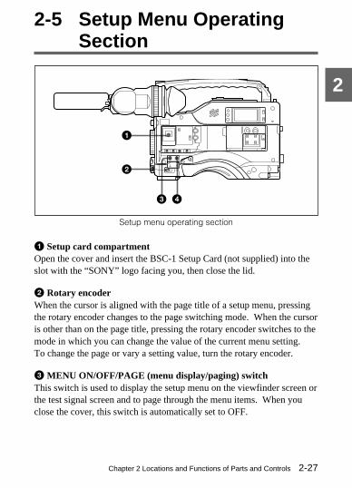
1 Setup card compartmentOpen the cover and insert the BSC-1 Setup Card (not supplied) into theslot with the “SONY” logo facing you, then close the lid.
2 Rotary encoderWhen the cursor is aligned with the page title of a setup menu, pressingthe rotary encoder changes to the page switching mode. When the cursoris other than on the page title, pressing the rotary encoder switches to themode in which you can change the value of the current menu setting.To change the page or vary a setting value, turn the rotary encoder.
3 MENU ON/OFF/PAGE (menu display/paging) switchThis switch is used to display the setup menu on the viewfinder screen orthe test signal screen and to page through the menu items. When youclose the cover, this switch is automatically set to OFF.
1
2
3 4
Chapter 2 Locations and Functions of Parts and Controls2-28
2
ON: Displays the setup menu on the viewfinder screen or the test signalscreen, at the page which was on the screen when the previous menuaccess ended.(When the menu is first used, the first page isdisplayed.)To enable the MENU CANCEL/PRST/ITEM switch, select thisposition.
OFF: Removes the setup menu from the viewfinder screen or the testsignal screen.
PAGE: Every time this switch is pushed down from the ON position, thenext page of the setup menu is displayed.
4 MENU CANCEL/PRST/ITEM (menu setting cancellation/menupresetting/item selection) switch
When the MENU ON/OFF/PAGE switch is set to ON, this switch isused to select an item on the setup menu or erase shot ID characters.CANCEL/PRST: Pushing the switch up to this position allows you to
cancel the previous settings, to reset the settings to their initialvalues, or to erase shot ID characters.
ITEM: Every time the switch is pushed down to this position, the cursor(arrow mark) in the page moves to the next item.
Note
Operation depends on the items displayed. Check the menu operationthat corresponds to the current item for details.

Chapter 2 Locations and Functions of Parts and Controls 2-29
2
2-6 Time Code System
Time code functions (1)
1 GENLOCK IN (genlock input) connector (BNC type)• This connector inputs a reference signal when the camera is to be
genlocked, or when the time code is to be synchronized with externalequipment.
• This connector also inputs a return video signal. You can display theimage in the viewfinder screen by setting CAM RET. of FUNCTION2/2 page to ON.
For more information, see Section 4-9-2 “Selecting the Functions.”(Page 4-79)
2 TC IN (time code input) connector (BNC type)To synchronize the time code with an external time code, connect thereference time code input here.
1
2
34

Chapter 2 Locations and Functions of Parts and Controls2-30
2
3 TC OUT (time code output) connector (BNC type)To synchronize the time code of an external VTR with that of thecamcorder, connect this connector to the time code input lock connectorof the external VTR.
4 TEST OUT (output) connector (BNC type)To synchronize the time code of an external VTR with that of thecamcorder, set the test output signal to composite video and connect thisconnector to the video input connector of the external VTR.For information about setting the test output, see page 2-24.

Chapter 2 Locations and Functions of Parts and Controls 2-31
2
Illustration: DVW-707/709WS/790WS (for the NTSC broadcast system)
Time code functions (2)
7
5
6
89
0qa
qs
qd
OFF
ON
DISPLAY
LIGHTRESET
HOLD
WARNINGCTLTC
DATA
ADVANCE
PRESET
F-RUNSET
DIAG
R-RUN
DATADISPLAY
NDFDF
REGEN
CLOCK
AUDIO INAUDIO SELECT
REAR
MIXCH-1 CH-2
FRONT
SHIFT
MANUALAUTO
LEVELCH-1••
••
•
• •
••
•
•
0 10
CH-2••
••
•
• •
••
•
•
CUE IN
0 10
U-BITSHOT TIME
NO.

Chapter 2 Locations and Functions of Parts and Controls2-32
2
5 HOLD (display hold) buttonPressing this button instantly freezes the time data displayed in thecounter display section. (The time code generator continues normaloperation.) Pressing this button again releases the hold. One use of thisfeature is to determine the exact time of a particular shot.See Section 2-8 “Warnings and Indications on the Display Panel” (page 2-38) formore information about the counter display.
6 RESET (counter reset) buttonThis button resets the time data displayed on the counter display sectionto “00 : 00 : 00 : 00” and the user bit data to “00000000”.
7 DISPLAY switchDepending on the settings of the F-RUN/SET/R-RUN switch and theREAL TIME switch, this switch selects data to display in the counterdisplay section, as follows:CTL: CTLTC: Time codeDATA: The item selected by the DATA DISPLAY switchFor more information, see “Time code displays” (page 2-40).
8 ADVANCE buttonFor setting the time code or user bits, each press of this buttonincrements the flashing digit selected by the SHIFT button. Pressing thisbutton while holding down the HOLD button decrements the flashingdigit.Hold down this button and press the SHIFT button to enter the VTRmenu mode.For details about the VTR menu, see Section 4-10 “VTR Menu Display in theDisplay Panel” (page 4-99).
9 SHIFT buttonFor setting the time code or user bits, this button selects the digit to bechanged. The selected digit flashes.For more information, see Section 4-5-2 “Setting the Time Code” (page 4-29).

Chapter 2 Locations and Functions of Parts and Controls 2-33
2
q; PRESET/REGEN (regeneration)/CLOCK switchThis switch determines the source of time code values.PRESET: Starts recording time code values on the tape from the
currently set value. This enables the F-RUN/SET/R-RUN switch.REGEN: Reads the existing time code on the tape, and sets the time
code starting value accordingly. Thus, even when there is anindefinite break in recording, this setting ensures that time codes onthe tape will be continuous. Regardless of the setting of the F-RUN/SET/R-RUN switch, the camcorder operates in R-RUN mode.
CLOCK: Makes the time code value coincide with the built-in clock.Regardless of the F-RUN/SET/R-RUN switch setting, the camcorderalways operates in F-RUN mode.
qa F-RUN/SET/R-RUN (free run/set/recording run) switchThis switch selects the operating mode of the internal time codegenerator.F-RUN: The time code advances regardless of whether the VTR is
operating. Use this position for synchronizing the time code with anexternal time code.
SET: Set the switch to this position to set the time code or user bits.R-RUN: The time code advances only during recording, making the time
code on the tape continuous.For more information, see Section 4-5-1 “Setting the User Bits” (page 4-27), andSection 4-5-2 “Setting the Time Code” (page 4-29).
qs DF/NDF (drop frame/non-drop frame) switch (DVW-707/709WS/790WS only)This switch selects whether the time code advances in drop frame modeor non-drop frame mode.DF: Drop frame modeNDF: Non-drop frame mode
Chapter 2 Locations and Functions of Parts and Controls2-34
2
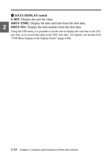
qd DATA DISPLAY switchU-BIT: Display the user bit value.SHOT-TIME: Display the date and time from the shot data.SHOT-NO.: Display the shot number from the shot data.Using the VTR menu, it is possible to set the unit to display the real time in the LTCuser bits, or to record shot data in the VITC user bits. For details, see Section 4-10“VTR Menu Display in the Display Panel” (page 4-99).

Chapter 2 Locations and Functions of Parts and Controls 2-35
2
2-7 Warnings and IndicationsThe camcorder gives visual information and warnings without yourhaving to look in the viewfinder.
Warning and indication functions
1
3
2
4
6
5
7
8
9
0
PRESET
F-RUNSET
DIAG
R-RUN
DATADISPLAY
NDFDF
REGEN
CLOCK
U-BITSHOT TIME
NO.

Chapter 2 Locations and Functions of Parts and Controls2-36
2
1 Tally indicatorSetting the TALLY switch to HIGH or LOW activates this indicator. Theindicator lights during recording on the VTR. It also provides the sameinformation as the REC indicator in the viewfinder: it comes on duringrecording and flashes to indicate a problem.
2 DISPLAY switchThis switches the indications on the viewfinder screen on or off.ON: The indications appear on the viewfinder screen.OFF: The indications do not appear on the viewfinder screen.
Note
When you turn the MENU ON/OFF/PAGE switch to ON, the menu willappear on the viewfinder screen even if the DISPLAY switch is off.
3 TALLY switchThis switch controls the tally indicator, setting its brightness (HIGH orLOW) or turning it off.
4 DIAG (diagnosis) buttonPressing this button when the VTR is stopped switches the camcorder tothe self-diagnosis mode. In the self-diagnosis mode, it is possible to carryout a display panel test, a VTR test, or a camera test, and to display thetest result.To exit from the self-diagnosis mode, press this button once more.Refer to “maintenance manual” for more information.
Caution
Do not press the DIAG button when a remote control unit is connected tothe REMOTE connector (8-pin). Pressing the button with a remotecontrol unit connected will disturb both the self-diagnostic and remotecontrol functions. The only remedy for this disturbance is to disconnectthe remote control unit and turn off the camcorder POWER switch.
Chapter 2 Locations and Functions of Parts and Controls 2-37
2
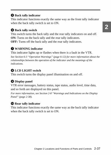
5 Back tally indicatorThis indicator functions exactly the same way as the front tally indicatorwhen the back tally switch is set to ON.
6 Back tally switchThis switch turns the back tally and the rear tally indicators on and off.ON: Turns on the back tally and the rear tally indicators.OFF: Turns off the back tally and the rear tally indicators.
7 WARNING indicatorThis indicator lights up or flashes when there is a fault in the VTR.See Section 6-3 “Operation Warnings” (page 6-12) for more information about therelationships between the operation of the indicator and the meanings of theindications.
8 LCD LIGHT switchThis switch turns the display panel illumination on and off.
9 Display panelVTR error messages, battery status, tape status, audio level, time data,and so forth are displayed on this panel.For more information, see Section 2-8 “Warnings and Indications on the DisplayPanel” (page 2-38).
q; Rear tally indicatorThis indicator functions exactly the same way as the back tally indicatorwhen the back tally switch is set to ON.

Chapter 2 Locations and Functions of Parts and Controls2-38
2Audio channel 1 level meter
Tape status indicator
Nearly dead: “BATT” flashes.Dead (battery must be charged): “BATT” and “E” flash.
Full (at beginning)
Close to end: “TAPE” flashes.End (tape must be replaced):“TAPE” and “E” flash.
Battery status indicator
2-8 Warnings and Indicationson the Display Panel
Tape status, battery status and level indicators
Tape status, battery status and level indicators
H MIN SEC FRM
40
PEAK dB
OVER EMPH OVER
TAPE E B
VH
HOLDDIAG PB VITC NDF EXT-LK
RF SERVO HUMID SLACK
00:00:00:00
BATT E x x x x x x x
x x x x x x x
F
1 2
30
10
0
•
20
TAPE E Bx x x x x x x
BATT E x x x x x x x F
Audio channel 2 level meter
Fully charged

Chapter 2 Locations and Functions of Parts and Controls 2-39
2
Warning indicatorsRF: Lights if the recording heads are clogged.SERVO: Lights if the servo motor fails.HUMID: Lights if condensation is on the drum.SLACK: Lights if the tape is not winding properly.For more information, see Section 6-3 “Operation Warnings” (page 6-12).
Lights in the self-diagnostic mode (testingdisplay panel, camera, and VTR).For more information, see Section 6-3“Operation Warnings” (page 6-12).
Lights during playback.
VTR operation and status indicators
VTR operation and status indicators
Note
If the tape in the VTR is slacked, an error code appears in the displaysection of the display panel.For more information, refer to “maintenance manual.”
H MIN SEC FRM
40
PEAK dB
OVER EMPH OVER
TAPE E B
VH
HOLDDIAG PB VITC NDF EXT-LK
RF SERVO HUMID SLACK
00:00:00:00
BATT E x x x x x x x
x x x x x x x
F
1 2
30
10
0
•
20
Chapter 2 Locations and Functions of Parts and Controls2-40
2
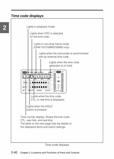
Lights when the time codegenerator is on hold.
Lights when VITC is selectedfor the time code.
Lights when the camcorder is synchronizedwith an external time code.
Lights when the time code,CTL, or real time is displayed.
Lights when the HOLDbutton is pressed.
Time counter display: Shows the time code,CTL, user bits, and real time.The table on the next page lists the details ofthe displayed items and switch settings.
Lights in playback mode.
Lights in non-drop frame mode(DVW-707/709WS/790WS only).
Time code displays
Time code displays
H MIN SEC FRM
40
PEAK dB
OVER EMPH OVER
TAPE E B
VH
HOLDDIAG PB VITC NDF EXT-LK
RF SERVO HUMID SLACK
00:00:00:00
BATT E x x x x x x x
x x x x x x x
F
1 2
30
10
0
•
20

Chapter 2 Locations and Functions of Parts and Controls 2-41
2
Relationships between the DISPLAY switch and DATADISPLAY switch settings and the time counter displaysExcept during setting of the time code, the time counter display isdetermined by the positions of the DISPLAY switch and DATADISPLAY switch.For details of setting the time code menu operation, see Section 4-5-2 “Setting theTime Code” (page 4-29).
Switch settings relating to time code and displayed information
DISPLAY switchposition
DATA DISPLAYswitch position
Displayedinformation
CTL Any position CTL
TC Any position Time code
DATA U-BIT User bits
SHOT-TIME Date and time fromshot data
SHOT-NO. Shot number from shotdata

Chapter 2 Locations and Functions of Parts and Controls2-42
2

Chapter 3 Recording and Playback 3-1
3
Recording and P
layback3-1 About CassettesThis section describes the procedure for loading and unloading acassette.See “Specifications” (page A-1) for information about the cassettes you can use inthe camcorder.
3-1-1 Loading and Unloading a CassetteLoading a cassette
1 Turn on the POWER switch.
(Continued)
If the interior of the VTR section is damp, the HUMID indicator willlight. If this happens, wait until the indicator goes off before goingon to step 2.
HUMID displayPOWER switch

Chapter 3 Recording and Playback3-2
3
2 Press the EJECT button.
The cassette lid will open.
3 Check that there is no slack in the tape, then slide in the cassetteuntil it clicks into position, and close the cassette lid completely bypressing near the engraved “PUSH”.
Cassette lid
Window outward
Insert the cassette.
Push and close thecassette lid.
1
2

Chapter 3 Recording and Playback 3-3
3
Checking the tape for slackPressing in the reels lightly, turn them gently with your fingers in thedirections shown below. If the reels will not move, there is no slack.
Checking the tape for slack
Unloading a cassetteWith the power supply on, press the EJECT button to open the cassettelid, then take out the cassette. If you are not going to insert anothercassette, close the cassette lid.It is possible to take out the cassette and close the cassette lid unless thebattery voltage drops below about 9 V.

Chapter 3 Recording and Playback3-4
3
Push the plug in.To reuse the cassette,return the plug to itsoriginal position.
Unloading a cassette manuallyIf the battery voltage drops below about 9V, take out the cassettemanually as illustrated below.
Unloading a cassette manually
You cannot lock the cassette lid after taking out the cassette, but turningon the power makes the cassette lid operable again.
3-1-2 Preventing Accidental ErasureThe following procedure prevents cassettes from being recordedinadvertently.
Preventing acidental erasure
Cassette lid
1 Turn the power off.2 Open this rubber cover.3 Pushing on the screw inside
with a screwdriver, turn thescrew counterclockwiseuntil the cassette lid opens.
4 Stop turning the screw assoon as the cassette lidopens.

Chapter 3 Recording and Playback 3-5
3
(Continued)
3-2 Recording
3-2-1 Basic ProcedureThis section describes the basic procedure for shooting and recording.Before a shooting session, make the checks listed in Section 6-1 “Testingthe Camcorder Before Shooting” (page 6-1) to ensure that the camcorderis functioning properly.
Turning on the camcorder and loading a cassetteFollow the procedure below.
Basic procedure for shooting : from power supply to cassette loading
1 Load a fully charged battery pack.
2 Set the POWER switch to ON. Check that the HUMID indicatordoes not appear and that the BATT indicator shows at least fivesegments. When using a BP-L60A/L90A battery pack, check thatthe four LED indicator segments on the battery pack are lit.• If the HUMID indicator appears, wait until it disappears.• If the BATT indicator does not show at least five segments,
replace the battery pack with a fully charged one.
Note
After turning off the power, check whether the drum is dry (even ifthe HUMID indication is off).
2
3 14

Chapter 3 Recording and Playback3-6
3
OUTPUT/DCC: CAM,DCC ON
Zoom: Automatic
Iris: Automatic
DISPLAY: ONAUDIO SELECT CH-1/CH-2: AUTO
F-RUN/SET/R-RUN:F-RUN or R-RUN(set as needed)
3 Check that there are no obstructions near the cassette lid, then pressthe EJECT button to open the cassette lid.
4 After checking the points below load the cassette, and close thecassette lid.• The cassette is not write-protected.• There is no slack in the tape.• The leader tape is wound on the take-up reel.
Basic procedure for shooting : from adjusting theblack balance and white balance to stopping recordingAfter turning on the power and loading a cassette, set the switches andselectors as shown below and begin operation.
Switch and selector settings before shooting

Chapter 3 Recording and Playback 3-7
3
(Continued)
ShootingFollow the procedure below.
Basic procedure for shooting: from adjusting the black balance andwhite balance to stopping recording
1 Push the AUTO W/B BAL switch to BLK to adjust the blackbalance.
2 Select the CC/ND filter (single filter for DVW-707/707P) to matchthe lighting conditions, and adjust the white balance.
When the black balance and white balance settings are alreadyin memory:Set the WHITE BAL switch to A or B.
When the white balance setting is not in memory and you do nothave enough time to adjust the white balance:
21,245,6
3,5

Chapter 3 Recording and Playback3-8
3
DVW-709WS/709WSP/790WS/790WSP
For automatic adjustment of the white balance, set the WHITE BALswitch to PRST, then the FILTER selector to B for 3200 K, to C for4300 K, or to D for 6300 K.
DVW-707/707P
Set the WHITE BAL switch to the PRST position. The whitebalance is automatically set to 3200 K when the FILTER knob is inposition 1, and to 5600 K in other positions.For more information, see Section 4-1-2 “Adjusting the White Balance” (page4-5)
3 Aim the camera at the object, and adjust the focus and zoom.
4 If necessary, set the electronic shutter for an appropriate mode andspeed.For more information, see Section 4-2 “Setting the Electronic Shutter” (page4-13).
5 To start recording, press the VTR START button or the VTR buttonon the lens.
During recording, the REC indicator in the viewfinder goes on.Perform zooming and focus control, if necessary.
6 To stop recording, press the VTR START button or the VTR buttonon the lens again.
The REC indicator goes off.
Cassette control buttonsDuring recording, the cassette control buttons (EJECT, REW, F FWD,PLAY, STOP) have no effect.

Chapter 3 Recording and Playback 3-9
3
3-2-2 Continuous RecordingIf the camcorder is in the recording pause mode, simply pressing theVTR START button on the camcorder or the VTR button on the lenscontinues recording at exactly the next frame.In other cases, you first need to position the tape at an appropriate pointto prevent the recording continuity from being lost.
When the camcorder is in the recording pause modePressing the VTR START button on the camcorder or the VTR button onthe lens positions the tape at the appropriate point automatically.However, the time taken before recording starts depends on the setting ofthe VTR SAVE/STBY switch.• If the VTR SAVE/STBY switch is in the SAVE position, it takes about
4 seconds before recording starts.• If the VTR SAVE/STBY switch is in the STBY position, recording
starts immediately. However, just after the switch position is changedfrom SAVE to STBY, it takes about 4 seconds before recording starts.
Chapter 3 Recording and Playback3-10
3
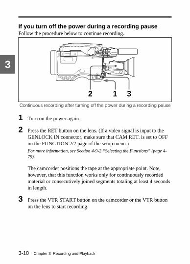
If you turn off the power during a recording pauseFollow the procedure below to continue recording.
Continuous recording after turning off the power during a recording pause
1 Turn on the power again.
2 Press the RET button on the lens. (If a video signal is input to theGENLOCK IN connector, make sure that CAM RET. is set to OFFon the FUNCTION 2/2 page of the setup menu.)For more information, see Section 4-9-2 “Selecting the Functions” (page 4-79).
The camcorder positions the tape at the appropriate point. Note,however, that this function works only for continuously recordedmaterial or consecutively joined segments totaling at least 4 secondsin length.
3 Press the VTR START button on the camcorder or the VTR buttonon the lens to start recording.
1 32

Chapter 3 Recording and Playback 3-11
3
Continuous recording in other casesAfter rewinding or fast forward, after removing the cassette, or on a tapethat has been partially recorded, you can obtain a continuous recordingby following the procedure below.
Continuous recording after rewinding or fast forward, after removing thecassette, or on a tape that has been partly recorded
1 Looking in the viewfinder, press the PLAY button to start playback.
2 Press the STOP button at the desired point to begin recording. Tocontinue from the end of recording already on the tape, press theSTOP button immediately after the end of the previous recording(within 0.5 seconds).
3 Press the RET button on the lens. When inputting a video signal tothe GENLOCK IN connector, make sure CAM RET. onFUNCTION 2/2 page of the setup menu is set to OFF.For more information, see Section 4-9-2 “Selecting the Functions” (page 4-79).
The tape will rewind and will be positioned at the desired point tocontinue recording in about 7 seconds.
4 Press the VTR START button on the camcorder or the VTR buttonon the lens to start recording.
43
21

Chapter 3 Recording and Playback3-12
3
3-2-3 Starting a Shoot with a Few Seconds ofPre-Stored Picture Data (Loop RecFunction) (When Using a BKDW-703Extension Board)
By installing the optional BKDW-703 extension board in the camcorder,the camcorder is able to constantly store a few seconds (up to 8 seconds)worth of the most current picture and sound data in the board’s memory.Thus, when you press the VTR START button or the VTR button on thelens, the recording starts with the data stored a few seconds before.
Turning Loop Rec mode on and off / Setting the LoopRec timeTo record in Loop Rec mode, you need to turn on Loop Rec mode andset the picture data storage time (Loop Rec time).
The Loop Rec time and VTR SAVE / STBY switch settings determinethe number of seconds of picture data that will be stored in the BKDW-703’s memory and recorded when you press the VTR START button orVTR button on the lens. The following table shows the approximatenumber of seconds worth of picture data (counting back from the timeyou begin recording) that will be recorded from memory. However,when changing from SAVE to STBY, or under the special situationsexplained in the notes on next page, the actual amount of data recordedmay be shorter.
Loop Rec time setting and recording start point
Loop Rec time VTR STBY mode VTR SAVE mode
8 (seconds) About 8 seconds before About 4 seconds before
4 (seconds) About 4 seconds before About the same time
2 (seconds) About 2 seconds before About 2 seconds after
1 (second) About 1 second before About 3 seconds after

Chapter 3 Recording and Playback 3-13
3
Notes
• If you change the Loop Rec mode settings, the picture data stored inmemory previous to the change are rendered unrecordable. Thus,when you press the VTR START button or VTR button on the lens, thepreviously stored picture data will not be recorded.
• Picture data is stored to the BKDW-703’s memory only for images thatappear in the viewfinder. For this reason, if you change to playback orrecording review during Loop Rec mode, then begin recordingimmediately afterwards, picture data corresponding to the duration ofplayback or recording review will not be in memory and will thereforenot be recorded to tape.
Follow the procedure below to turn Loop Rec mode on.
1 Set the MENU ON/OFF/PAGE switch to ON.
The page that was on the viewfinder screen when the last menuoperation ended will appear again. (If the menu is being used for thefirst time, the lowest page of the selected pages will appear).
(Continued)
1,2,6
4,5
3

Chapter 3 Recording and Playback3-14
3
2 Push the MENU ON/OFF/PAGE switch repeatedly towards PAGE(or use the rotary encoder) until the OPERATION 2 page shown asbelow appears.
OPERATION 2 page
Note
If the BKDW-703 is not installed, the items for LOOPRECORDING are not displayed on the OPERATION 2 page.
3 Push the MENU CANCEL/PRST/ITEM switch repeatedly towardsITEM (or use the rotary encoder) to move the right arrow cursor toLOOP RECORDING: OFF.
4 Push the rotary encoder once.
The right arrow cursor moves to the left of OFF as shown below:LOOP RECORDING: tOFF
? 37*OPERATION 2
AWB LEVEL GATE : ON
COLOR VF : COMP
REC TALLY : UPPER
TIME CODE DISP : OFF
LOOP RECORDING : OFF The state of a Loop Rec modesetting
Chapter 3 Recording and Playback 3-15
3
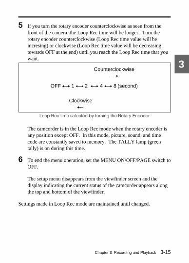
5 If you turn the rotary encoder counterclockwise as seen from thefront of the camera, the Loop Rec time will be longer. Turn therotary encoder counterclockwise (Loop Rec time value will beincresing) or clockwise (Loop Rec time value will be decreasingtowards OFF at the end) until you reach the Loop Rec time that youwant.
Loop Rec time selected by turning the Rotary Encoder
The camcorder is in the Loop Rec mode when the rotary encoder isany position except OFF. In this mode, picture, sound, and timecode are constantly saved to memory. The TALLY lamp (greentally) is on during this time.
6 To end the menu operation, set the MENU ON/OFF/PAGE switch toOFF.
The setup menu disappears from the viewfinder screen and thedisplay indicating the current status of the camcorder appears alongthe top and bottom of the viewfinder.
Settings made in Loop Rec mode are maintained until changed.
Counterclockwise
Clockwise
t
OFF y 1 y 2 y 4 y 8 (second)
T

Chapter 3 Recording and Playback3-16
3
You can turn Loop Rec mode on and off by pressing the ASSIGNABLEbutton on the side of the camcorder.For more information on ASSIGNABLE button, see section 4-9-2 “Selecting the
Functions” (page 4-79).
Note
You can change the Loop Rec mode menu settings while recording; anychanges that you make, however, do not take effect until after therecording operation is completed.
Camcorder operations in Loop Rec modeThe recording procedure in Loop Rec mode is basically the same as thatfor normal recording. Please note, however, the following differences.
• When you record in Loop Rec mode, the picture you shoot is recordedto the tape after an elapse of the Loop Rec time. For this reason, thetape does not stop immediately when you press the STOP button.After pressing the STOP button, the REC lamp begins flashing onceevery second and all tape operation buttons (EJECT, REW, F FWD,PLAY, and STOP) stop functioning until the Loop Rec time haselapsed. Afterwards, you can begin recording again by pressing theVTR START button or VTR button on the lens.After pressing the STOP button, if you start recording before a timeequal to the Loop Rec time has elapsed, there will be no break in therecorded footage (i.e., it will be as if there were not a pause inrecording).For example, if you press the STOP button with the Loop Rec time setat 8 seconds, you could press the VTR START button 7 seconds laterand there would be no break in the recorded material.
• In Loop Rec mode, the time code generator in the camcorder advancesconstantly at all times, not only during recording. It does this togenerate continuous time code data in the memory. For this reason, itis not possible to use the time code for REC RUN mode operations.
Chapter 3 Recording and Playback 3-17
3
• The time code stops advancing while time data is being set (when theF-RUN/SET/R-RUN switch is set to SET). For this reason, if you startrecording immediately after switching to F-RUN or R-RUN (i.e., to aposition other than SET), you may overwrite a portion of thepreviously recorded time code.
• Recontinuation recording in Loop Rec mode is done in the same wayas normal recording. In Loop Rec mode, however, when recording isrecontinued, the Loop Rec time is subject to a decrease of up to 0.3second. (DVW-707/709WS/790WS only)
Turning off the camera• When you turn the POWER switch to OFF, the camera will turn off by
itself after the tape has run for a few seconds.• If you remove the battery, pull out the DC cable, or cut the power to
the AC adaptor during recording, the image currently being shot on thecamcorder will not be recorded. For this reason, take care not tochange the battery while recording.
When the tape runs out during recordingPlease note that picture data at the instant the tape stopped is notrecorded if the tape runs out and the camcorder stops. The recordedpicture data is interrupted before the recording stop point.
Chapter 3 Recording and Playback3-18
3
3-2-4 Reversing the picture orientation(vertically and horizontally) (Using theBKDW-704 Extension Board) (DVW-709WS/709WSP/790WS/790WSP only)
If you have installed the optional BKDW-704 extension board into thecamcorder and are using a cinema lens, you can reverse the orientation ofthe image (vertically and horizontally) and record the reversed image asa normal image.
Setting the Picture OrientationUse REVERSE IMAGE and H DELAY of OPERATION 2 page of thesetup menu to reverse the picture orientation and horizontally center theimage. To reverse the picture, set REVERSE IMAGE to ON, and use HDELAY to make fine horizontal adjustments of the picture. (H DELAYadjustments are possible only when the picture orientation is reversed.Phase has no effect on pictures which are not reversed.)
Note
After making a horizontal adjustment with H DELAY, always do a testrecording on your system and play it back to verify that the entire picturefills the screen in the horizontal direction. Any drastic change in the Hphase from the factory setting may cause the picture to be cut off at theends, depending on the blanking width and other settings in your editingsystem.

Chapter 3 Recording and Playback 3-19
3
3-3 Checking the Recording— Playback
By pressing the PLAY button, you can review any length of therecording in the viewfinder in black and white. There are two other waysto review the recording.Recording review: You can see the last 2 seconds of the recording in the
viewfinder in black and white.Color playback: You can see the recording in color on a color video
monitor without the need for any external adaptor.
You can also view the picture by pressing the REW button or F FWDbutton during playback.See Section 2-3 “Audio Functions” (page 2-5), for information about the switchesand controls used to select the audio output signal and to adjust the audio level.
3-3-1 Checking the Last Two Seconds of theRecording — Recording Review
If you press the RET button on the lens while recording is paused, thelast two seconds of the tape is automatically rewound, and that segmentis played back on the viewfinder screen. Use this function to checkwhether recording went smoothly. If you hold the RET button downlonger, at most 10 seconds of the tape is rewound and played back.After playback, the camcorder is ready to start recording again.
Set CAM RET. to OFF on the FUNCTION 2/2 page of the setup menuwhen inputting a return video signal to the GENLOCK IN connector.For information about setting the CAM RET. function, see Section 4-9-2 “Selectingthe Functions” (page 4-79).
Note
The recording review function only works if the recording you havemade is at least 2 seconds long.

Chapter 3 Recording and Playback3-20
3
3-3-2 Checking the Recording on the ColorVideo Monitor — Playback in Color
Connect a color video monitor to the VIDEO OUT connector of thecamcorder, and press the PLAY button.
Color playback
VIDEO OUT
Color video monitor
Video inputconnector

Chapter 4 Adjustments and Settings for Recording 4-1
4
Adjustm
ents and Settings for R
ecording4-1 Adjusting the Black
Balance and the WhiteBalance
Conditions may require that both the black balance and the white balancebe adjusted.
The black balance will require adjustment in the following cases.• When the camcorder is first used• When the camcorder is used under conditions in which the surrounding
temperature has changed greatly• When the GAIN selector values have been changedIt is not usually necessary to adjust the black balance when using thecamcorder after it has been briefly off.
Always readjust the white balance when the lighting conditions change.
If the black balance or white balance adjustment is started when thedisplay mode is set to 2 or 3, messages that report on the adjustmentprogress and results are displayed on the viewfinder screen. Change thedisplay mode to 1 to suppress these messages.For information about setting the display mode, see Section 4-8-3 “Display Modeand Setting Change and Adjustment Progress Messages” (page 4-61).

Chapter 4 Adjustments and Settings for Recording4-2
4
4-1-1 Adjusting the Black BalanceIn automatic black balance mode, the black balance is adjusted after theblack set is adjusted.Manual black balance adjustment can be selected from the setup menu.Refer to “maintenance manual ” for information about manual black balanceadjustment.
Follow the procedure below to adjust the black balance.
1 Set the switches as follows:
If you change the setting of the GAIN selector, a message reportingthe set position appears in the setting change and adjustmentprogress message display area of the viewfinder screen for about 3seconds (in display mode 3).
OUTPUT/DCC: CAM
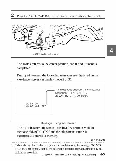
Chapter 4 Adjustments and Settings for Recording 4-3
4
2 Push the AUTO W/B BAL switch to BLK, and release the switch.
The switch returns to the center position, and the adjustment iscompleted.
During adjustment, the following messages are displayed on theviewfinder screen (in display mode 2 or 3).
Message during adjustment
The black balance adjustment ends in a few seconds with themessage “BLACK : OK,” and the adjustment setting isautomatically stored in memory.
The messages change in the followingsequence : -BLACK SET- →-BLACK BAL- 1) → -CHECK-
(Continued)
AUTO W/B BAL switch
....................................................................................................................................1) If the existing black balance adjustment is satisfactory, the message “BLACK
BAL” may not appear, that is, the automatic black balance adjustment may beomitted to save time.
BLACK:OP
-BLACK SET-

Chapter 4 Adjustments and Settings for Recording4-4
4
Notes
• During the black balance adjustment, the iris is automatically closed.• During the black balance adjustment, the gain selection circuit is
automatically activated so you may see flickering on the viewfinderscreen, but this is not a fault.
If automatic black balance adjustment cannot be madeIf the black balance adjustment cannot be completed normally, an errormessage will appear for about 3 seconds on the viewfinder screen (indisplay mode 2 or 3).Possible messages are listed on the next page.
Black balance adjustment error messages
Error message Meaning
If any of the above error messages is displayed, retry the black balanceadjustment. If the error message occurs again, an internal check isnecessary.Refer to “maintenance manual” for information about this internal check.
Note
If the lens cable is not firmly connected to the lens connector (see2-2), it may not be possible to adjust the lens iris. If this happens, theblack balance will be incorrect.
BLACK : NGIRIS NOT CLOSED
BLACK : NGR (or G or B) : TIME LIMIT
BLACK : NGR (or G or B) : OVERFLOW
The lens iris did not close; adjustment wasimpossible.
Adjustment could not be completed within thestandard number of attempts.
The difference between the reference valueand the current value is so great that itexceeds the range. Adjustment wasimpossible.
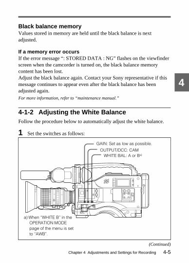
Chapter 4 Adjustments and Settings for Recording 4-5
4
Black balance memoryValues stored in memory are held until the black balance is nextadjusted.
If a memory error occursIf the error message “: STORED DATA : NG” flashes on the viewfinderscreen when the camcorder is turned on, the black balance memorycontent has been lost.Adjust the black balance again. Contact your Sony representative if thismessage continues to appear even after the black balance has beenadjusted again.For more information, refer to “maintenance manual.”
4-1-2 Adjusting the White BalanceFollow the procedure below to automatically adjust the white balance.
1 Set the switches as follows:
a) When “WHITE B” in theOPERATION MODEpage of the menu is setto “AWB”.
GAIN: Set as low as possible.
WHITE BAL: A or Ba)
OUTPUT/DCC: CAM
(Continued)

Chapter 4 Adjustments and Settings for Recording4-6
4
If the setting of the GAIN selector or WHITE BAL switch ischanged, a message reporting the set position appears for about 3seconds in the setting change and adjustment progress messagedisplay area of the viewfinder screen (in display mode 3 (see 4-8-3)).
2 Adjust the FILTER selector to suit the lighting conditions.
The relationships between the various selector settings and filterselections are listed in the tables below.
DVW-707/707P
FILTER knob setting and filter
FILTER knob setting Filter
1 3200 K
2 5600 K + 1/8 ND
3 5600 K
4 5600 K + 1/64 ND

Chapter 4 Adjustments and Settings for Recording 4-7
4
DVW-709WS/709WSP/790WS/790WSP
FILTER knob (outer) setting and CC filter
FILTER knob (outer) setting CC filter
A Cross filter
B 3200 K
C 4300 K
D 6300 K
FILTER knob (inner) setting and ND filter
FILTER knob (inner) setting ND filter
1 Straight through
2 1/4 ND
3 1/16 ND
4 1/64 ND
For examples of FILTER selector settings, see the description of the FILTERselector in Section 2-4 “Shooting and Recording/Playback Functions” (page2-14).
If the setting of the FILTER selector is changed, a message reportingthe setting appears for about 3 seconds in the setting change andadjustment progress message display area of the viewfinder screen(in display mode 3).
3 Place a white test card under the same lighting conditions as thesubject to be shot, and zoom up to it. Alternatively, any white objectsuch as a cloth or a wall could be used.
(Continued)

Chapter 4 Adjustments and Settings for Recording4-8
4
The absolute minimum white area is as follows:
4 Adjust the lens iris.
If the lens is manually adjusted, adjust it as appropriate. If the lenshas an automatic iris, set the automatic/manual switch on the lens toautomatic.
5 Push the AUTO W/B BAL switch to WHT, and release the switch.
Rectangle centered on the screen:the lengths of the sides are 70% ofthe length or the width of the screen.
NoteMake sure there are no bright spots inthe rectangle.
The white object must be withinthe rectangle and have an area ofat least 10% of the screen.
AUTO W/B BAL switch

Chapter 4 Adjustments and Settings for Recording 4-9
4
The switch returns to the center position, and the adjustment iscompleted.
During adjustment, the message “WHITE : OP” is displayed on theviewfinder screen (in display mode 2 or 3).
The white balance adjustment ends in a second with the message“WHITE : OK”, and the adjustment setting is automatically stored inthe memory (A or B) that was selected in step 1.
Note
If the camera has a zoom lens with an automatic iris, the iris may hunt 1)
during the adjustment. To prevent this, adjust the iris gain knob (markedwith IG, IS, or S) on the lens.For more information, refer to the lens operation manual.
Approximate color temperatureof the object
....................................................................................................................................1) Hunting
Repeated brightening and darkening of an image, resulting from repeatedresponses to automatic iris control.
WHITE:OK
K

Chapter 4 Adjustments and Settings for Recording4-10
4
If automatic white balance adjustment cannot be madeIf the white balance adjustment cannot be completed normally, an errormessage will appear for about 3 seconds on the viewfinder screen (indisplay mode 2 or 3).Possible messages are listed below.
White balance adjustment error messages
Error message Meaning
If any of the above error messages is displayed, retry the white balanceadjustment. If the error message occurs again, an internal check isnecessary.Refer to “maintenance manual” for information about this internal check.
WHITE : NGLOW LEVEL
The white video level is too low. Either makeopen the lens iris or increase the gain.
WHITE : NGCOLOR TEMP. HIGH
The color temperature is too high. Select asuitable filter setting.
WHITE : NGCOLOR TEMP. LOW
The color temperature is too low. Select asuitable filter setting.
WHITE : NGTIME LIMIT
Adjustment could not be completed within thestandard number of attempts.
WHITE : NGPOOR WHITE AREA
The white area could not be checked.
WHITE : NGLEVEL TOO HIGH
The white video level is too high. Either narrowthe lens iris opening or change the ND filter.

Chapter 4 Adjustments and Settings for Recording 4-11
4
If you have no time to adjust the white balance
DVW-709WS/709WSP/790WS/790WSP
For automatic adjustment of the white balance, set the WHITE BALswitch to PRST, then the FILTER selector to B for 3200 K, to C for4300 K, or to D for 6300 K.
DVW-707/707P
Set the WHITE BAL switch to PRST. The white balance isautomatically set to 3200 K when the FILTER selector is in position 1,and to 5600 K in other positions.For details about setting the white balance manually, see section 4-1-2 “Adjust theWhite Balance ”(page 4-5).
White balance memoryValues stored in memory are held until the white balance is nextadjusted.There are two sets of white balance memories, A and B, and adjustmentsfor each of the filters can be automatically stored in the memorycorresponding to the setting (A or B) of the WHITE BAL switch. Thecamcorder has four built-in filters, so a total of eight (4 × 2) adjustmentscan be stored. The number of memories allocated each A and B can belimited to one each by setting FILTER INH. to ON on the FUNCTION2/2 page of the setup menu. In this case, the memory contents are notlinked to the filters.When the WHITE BAL switch is set to B whereas, in the setup menuOPERATION 1 page, “WHITE B” is set to ATW, the ATW function isactivated to automatically adjust the white balance of the picture beingshot for varying lighting conditions.

Chapter 4 Adjustments and Settings for Recording4-12
4
If a memory error occursIf the error message “: STORED DATA : NG” flashes on the viewfinderscreen when the camcorder is turned on, the white balance memorycontent has been lost.Adjust the black balance and the white balance again. Contact your Sonyrepresentative if this message continues to appear even after the blackbalance and the white balance have been adjusted again.For more information, refer to “maintenance manual.”

Chapter 4 Adjustments and Settings for Recording 4-13
4
(Continued)
4-2 Setting the ElectronicShutter
This section describes the shutter modes that can be used with theelectronic shutter of the camcorder, and describes the procedure forselecting the shutter speed and mode.
4-2-1 Shutter ModesThe shutter modes that can be used with the electronic shutter and theshutter speeds that can be selected are listed below.
Selectable shutter modes and speeds
Mode Shutter speed Application
Standard DVW-707/709WS/790WS:1/100, 1/125,1/250, 1/500,1/1000, or 1/2000 sec.
For shooting fast-moving subjectswith little blurring.
DVW-707P/709WSP/790WSP: 1/60, 1/125,1/250, 1/500, 1/1000, or1/2000 sec.
CLS(ClearScan)
DVW-707: 261 speeds inthe range of 60.3 Hz to10156 HzDVW-709WS/790WS: 260speeds in the range of 60.1Hz to 7000Hz
For shooting subjects such asmonitor screens with verticalscanning frequencies of over60 Hz (DVW-707/709WS/790WS)or over 50 Hz(DVW-707P/709WSP/790WSP),to obtain images with nohorizontal bands of noise.
DVW-707P: 312 speeds inthe range of 50.0 Hz to10101 HzDVW-709WSP/790WSP:310 speeds in the range of50.2 Hz to 9000 Hz
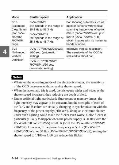
Chapter 4 Adjustments and Settings for Recording4-14
4
Mode Shutter speed Application
ECS(ExtendedClear Scan)(For DVW-790WS/790WSPonly)
DVW-790WS:248 speeds in the range of30.4 Hz to 58.3 Hz
Notes
• Whatever the operating mode of the electronic shutter, the sensitivityof the CCD decreases with increasing shutter speed.
• When the automatic iris is used, the iris opens wider and wider as theshutter speed increases, thus reducing the depth of field.
• Under artificial light, particularly fluorescent or mercury lamps, thelight intensity may appear to be constant, but the strengths of each ofthe R, G and B colors are actually changing in synchronization with thefrequency of the power supply (“flicker”). Using an electronic shutterunder such lighting could make the flicker even worse. Color flicker isparticularly likely to happen when the power supply is 60 Hz (with theDVW-707/709WS/790WS) or 50 Hz (with the DVW-707P/709WSP/790WSP). However, if the power frequency is 50 Hz (DVW-707/709WS/790WS) or 60 Hz (DVW-707P/709WSP/790WSP), setting theshutter speed to 1/100 or 1/60 can reduce this flicker.
For shooting subjects such asmonitor screens with verticalscanning frequencies of up to60 Hz (DVW-790WS) or up to50 Hz (DVW-790WSP), toobtain images with no horizontalbands of noise.
DVW-790WSP:295 speeds in the range of25.4 Hz to 48.7 Hz
EVS(EnhancedVerticalDefinition)
DVW-707/709WS/790WS:1/60 sec. (automaticsetting)
Improved vertical resolution.The sensitivity of the CCD isreduced to about half.
DVW-707P/709WSP/790WSP: 1/50 sec.(automatic setting)

Chapter 4 Adjustments and Settings for Recording 4-15
4
(Continued)
• When a bright object is shot in EVS mode or ECS mode (DVW-790WS/790WSP only) in such a manner that it fills the screen, theupper edge of the picture may have poor quality because of an inherentcharacteristic of CCD. Before using EVS mode, check the shootingconditions.
• When using the electronic shutter, set FIELD/FRAME to FLD (fieldaccumulation mode) on the FUNCTION 2/2 page of the setup menu.
4-2-2 Selecting the Shutter Mode and SpeedUse the SHUTTER selector to select a shutter mode or a standard-modeshutter speed. To set the shutter speed in CLS/ECS mode, with theSHUTTER switch set to ON and the CLS/ECS mode selected, turn therotary encoder.You can use the SHUTTER page of the setup menu to narrow the rangeof choice in advance, or to select in advance whether you use CLS, ECSor EVS mode.
Setting the shutter mode and standard-mode shutterspeed
1 Follow the procedure described in “Changing the display mode”(page 4-63) to set the display mode to 2 or 3 from the VF DISP pageof the setup menu.

Chapter 4 Adjustments and Settings for Recording4-16
4SHUTTER selector
2 Open the SHUTTER selector cover, then push the SHUTTERselector from ON to SEL.
The current shutter setting appears for about 3 seconds in the settingchange and adjustment progress message display area of theviewfinder screen.
E.g.: SS : 1/250 or : CLS : 60.6 Hz
3 Before the message from step 2 disappears, push the SHUTTERselector to SEL again and repeat until the desired mode or speedappears.
Pushing the SHUTTER selector to SEL repeatedly allows you tocycle through the settings of mode and speed preselected on theSHUTTER page of the setup menu.Note that all modes and all standard-mode speeds listed in the tableon page 4-12 are preselected using the SHUTTER page of the setupmenu.For more information about the SHUTTER page, see “Changing the range ofchoice of shutter mode and speed settings” (page 4-19).

Chapter 4 Adjustments and Settings for Recording 4-17
4a) Either CLS mode or ECS mode (DVW-790WS/790WSP only) is selected
depending on the shutter speed set in the setup menu CLEAR SCANpage.
Standard mode
1/100 (or 1/60) t 1/125 t 1/250 t 1/500 t 1/1000 t 1/2000
Selectable settings of shutter mode and speed (factory setting)
Once a shutter speed is selected, it is maintained until the next shutterspeed setting operation.When the message “STORED DATA:NG” appears, the shutter speedreturns to 1/100 s (DVW-707/709WS/790WS) or 1/60 s(DVW-707P/709WSP/790WSP).
Setting the shutter speed in CLS modeFollow the procedure below.
Setting the shutter speed in CLS mode
EVS modeCLS/ECS mode a)
1 2
(Continued)
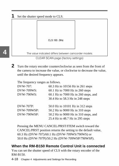
Chapter 4 Adjustments and Settings for Recording4-18
4 The value indicated differs between camcorder models.
1 Set the shutter speed mode to CLS.
CLEAR SCAN page (factory settings)
2 Turn the rotary encoder counterclockwise as seen from the front ofthe camera to increase the value, or clockwise to decrease the value,until the desired frequency appears.
The frequency ranges as follows.DVW-707: 60.3 Hz to 10156 Hz in 261 stepsDVW-709WS: 60.1 Hz to 7000 Hz in 260 stepsDVW-790WS: 60.1 Hz to 7000 Hz in 260 steps, and
30.4 Hz to 58.3 Hz in 248 steps
DVW-707P: 50.0 Hz to 10101 Hz in 312 stepsDVW-709WSP: 50.2 Hz to 9000 Hz in 310 stepsDVW-790WSP: 50.2 Hz to 9000 Hz in 310 steps, and
25.4 Hz to 48.7 Hz in 295 steps
Pressing the MENU CANCEL/PRST/ITEM switch toward theCANCEL/PRST position returns the setting to the default value,60.3 Hz (DVW-707)/60.1 Hz (DVW-709WS/790WS) or50.0 Hz (DVW-707P)/50.2 Hz (DVW-709WSP/790WSP).
When the RM-B150 Remote Control Unit is connectedYou can set the shutter speed of CLS with the rotary encoder of theRM-B150.
CLS:60.3Hz CLS:60.3Hz

Chapter 4 Adjustments and Settings for Recording 4-19
4
When the RM-P9 Remote Control Unit is connectedYou can set the shutter speed of CLS using the UP/DOWN switch of theRM-P9.
Changing the range of choice of shutter mode andspeed settingsYou can reduce the time required to select the shutter mode and speed bynarrowing the choice of settings in advance. This can be done by usingthe SHUTTER page of the setup menu.Follow the procedure below.
Note
The SHUTTER page cannot be accessed when a remote control unit isconnected to the camcorder.
Changing the range of choice of shutter mode and speed settings
1 Set the MENU ON/OFF/PAGE switch to ON.
The page that was on the screen when the last menu operation endedappears on the viewfinder screen. (When this menu is first used, thelowest-numbered page of the currently selected pages forconfiguring the menu appears.)
(Continued)
1,2,3,5
2,3,4

Chapter 4 Adjustments and Settings for Recording4-20
4
CLS mode
EVS mode
Shutter speeds selectablein standard mode
2 Push the MENU ON/OFF/PAGE switch repeatedly to PAGE untilthe SHUTTER page shown as below appears (or use the rotaryencoder).
SHUTTER page (factory settings)
3 Push the MENU CANCEL/PRST/ITEM switch repeatedly to ITEMuntil the cursor reaches the mode or shutter speed you want (or usethe rotary encoder).
4 To use the selected mode or speed (the “ON” setting), turn the rotaryencoder counterclockwise as seen from the front of the camera. Inorder not to use it (the “OFF” setting), turn the rotary encoderclockwise.
Note that pushing the MENU CANCEL/PRST/ITEM switch toCANCEL/PRST has no effect on the SHUTTER page. To selectanother mode or speed, return to step 3.
5 To end the menu operation, set the MENU ON/OFF/PAGE switch toOFF. (When you close the cover, the MENU ON/OFF/PAGE switchis set to OFF automatically.)
The setup menu disappears from the viewfinder screen and thedisplay indicating the current status of the camcorder appears alongthe top and bottom of the viewfinder.
a) 1/100 for DVW-707/709WS/790WS or 1/60 for DVW-707P/709WSP/790WSP
?E09*SHUTTER
EVS : ON
CLS : ON
1/60 : ON
1/125 : ON
1/250 : ON
1/500 : ON
1/1000 : ON
1/2000 : ON
Chapter 4 Adjustments and Settings for Recording 4-21
4
(Continued)
4-3 Changing the ReferenceValue for Automatic IrisAdjustment
The reference value for automatic iris adjustment can be changed toenable the shooting of clear pictures of back-lit subjects, or to obtainspecial effects. The reference value for the lens iris can be set within thefollowing range with respect to the standard value as defined by an Fnumber.• 0.25: about 0.25 stop further open• 0.5: about 0.5 stop further open• −0.25: about 0.25 stop further closed• −0.5: about 0.5 stop further closed
To change the reference value, set A. IRIS OVERRIDE to ON (factorysetting is OFF) on the FUNCTION 2/2 page of the setup menu.
The reference value is normally set to the standard value. Even if thereference value is changed, it reverts to the standard value every time thepower is turned on.
Opening or closing the lens iris
1 Set the MENU ON/OFF/PAGE switch to OFF to close the menu.
2 • To open the iris by 0.25 stop: turn the rotary encodercounterclockwise as seen from the front of the camera.One bar appears in the upper part to the left of the F number in theiris indication.
• To open the iris by 0.5 stop: turn the rotary encoder furthercounterclockwise as seen from the front of the camera.Two bars appear in the upper part to the left of the F number in theiris indication.

Chapter 4 Adjustments and Settings for Recording4-22
4
Closing the lens iris
Iris closed by 0.25 stop(one bar)
Iris closed by 0.5 stop(two bars)
Iris opened by 0.25 stop(one bar)
Iris opened by 0.5 stop(two bars)
Opening the lens iris
• To close the iris by 0.25 stop: turn the rotary encoder clockwise asseen from the front of the camera.One bar appears in the lower part to the left of the F number in theiris indication.
• To close the iris by 0.5 stop: turn the rotary encoder furtherclockwise as seen from the front of the camera.Two bars appear in the lower part to the left of the F number in theiris indication.
Opening or closing the lens iris
F5.6
F5.6
F5.6

Chapter 4 Adjustments and Settings for Recording 4-23
4
When the RM-B150 Remote Control Unit is connectedThe IRIS control knob of the RM-B150 can be used for lens iris setting.The bar display (π) will not appear, however.
When the RM-P9 Remote Control Unit is connectedThe IRIS control knob of the RM-P9 can be used for lens iris setting.The bar display (π) will not appear, however.

Chapter 4 Adjustments and Settings for Recording4-24
4
4-4 Adjusting the Audio LevelIf you set the AUDIO SELECT CH-1/CH-2 switches to AUTO, the inputlevels for the corresponding channels are adjusted automatically.
Follow the procedure below to manually adjust the level for both audiochannels.
Audio level manual adjustment
1 Set the AUDIO SELECT CH-1/CH-2 switches to MANUAL.
2 Adjust the AUDIO LEVEL CH-1/CH-2 controls so that at themaximum sound level the level meter indicates −20 dB.
12

Chapter 4 Adjustments and Settings for Recording 4-25
4
(Continued)
Adjusting the audio level of the microphoneYou can adjust the audio level input from the microphone for channels 1and 2 by using the MIC AUDIO LEVEL control on the front of thecamcorder.
Microphone audio level adjustment
1 Set either or both AUDIO IN switches to FRONT as follows:• When using the front microphone input for both channels 1 and 2:
Set both AUDIO IN switches to FRONT.• When using the front microphone input for either channel 1 or 2:
Set the AUDIO IN switch for the desired channel to FRONT.
2 Set the AUDIO SELECT switch(es) for the desired channel(s) toMANUAL.
3 Set the DISPLAY switch at the viewfinder to ON.
The audio level indication of the channel 1 will appear in theviewfinder.
12
5
3
4

Chapter 4 Adjustments and Settings for Recording4-26
4
Off
These bars go on.
These bars go on.
Excessive input levelNormal input level
Corresponding peak value
4 Use the MONITOR switch to select the channel whose audio levelis indicated in the viewfinder.CH1: Audio level of CH-1CH2: Audio level of CH-2MIX: Mixed audio level of CH-1 and CH-2
5 Turn the MIC AUDIO LEVEL control on the front of the camcorderto adjust the audio level while seeing the audio level indication onthe window screen.• When the incoming audio level is normal, the nine bars from the
bottom are on.• The second bar from the top may turn on occasionally, but do not
allow the top bar to go on. If it goes on, the audio level is too high.
4030
10
0
•
20

Chapter 4 Adjustments and Settings for Recording 4-27
4
(Continued)
Illustration: DVW-707/709WS/790WS (for the NTSC broadcast system)
4-5 Setting the Time Data
4-5-1 Setting the User BitsBy setting the user bits (up to hexadecimal 8 digits), you can record userinformation such as the date, time, or scene number on the time codetrack.Follow the procedure below to set the user bits.
Setting the user bits
1 Set the DISPLAY switch of the camcorder to DATA.
1
2,5
3
4
OFF
ON
DISPLAY
LIGHTRESET
HOLD
WARNINGCTLTC
DATA
ADVANCE
PRESET
F-RUNSET
DIAG
R-RUN
DATADISPLAY
NDFDF
REGEN
CLOCK
AUDIO INAUDIO SELECT
REAR
MIXCH-1 CH-2
FRONT
SHIFT
MANUALAUTO
LEVELCH-1••
••
•
• •
••
•
•
0 10
CH-2••
••
•
• •
••
•
•
CUE IN
0 10
U-BITSHOT TIME
NO.
H MIN SEC FRM
40
PEAK dB
OVER EMPH OVER
TAPE E B
VH
HOLDDIAG PB VITC NDF EXT-LK
RF SERVO HUMID SLACK
00:00:00:00
BATT E x x x x x x x
x x x x x x x
F
1 2
30
10
0
•
20

Chapter 4 Adjustments and Settings for Recording4-28
4
2 Set the F-RUN/SET/R-RUN switch to SET.
3 Set the DATA DISPLAY switch to U-BIT.
4 Set the user bits, using the SHIFT and ADVANCE buttons.SHIFT: Selects a digit to set. Each time you press it, the flashing
column moves one to the right.Pressing this button while holding down the HOLD buttonmoves the flashing digit one to the left.
ADVANCE: Increments the value of the flashing digit.Pressing this button while holding down the HOLD buttondecrements the flashing digit.
Hexadecimal digits A to F are displayed as follows:
Hexadecimal A B C D E F
Display A b C d E F
5 Set the F-RUN/SET/R-RUN switch to F-RUN or R-RUN.
The specified user bits will be recorded in the LTC and VITC.
Storing the user bits in memoryThe user bits setting (apart from the real time) is stored in memory whenthe power is turned off.
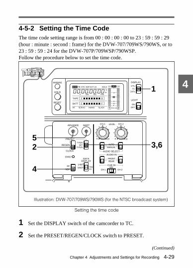
Chapter 4 Adjustments and Settings for Recording 4-29
4
Illustration: DVW-707/709WS/790WS (for the NTSC broadcast system)
(Continued)
4-5-2 Setting the Time CodeThe time code setting range is from 00 : 00 : 00 : 00 to 23 : 59 : 59 : 29(hour : minute : second : frame) for the DVW-707/709WS/790WS, or to23 : 59 : 59 : 24 for the DVW-707P/709WSP/790WSP.Follow the procedure below to set the time code.
Setting the time code
1 Set the DISPLAY switch of the camcorder to TC.
2 Set the PRESET/REGEN/CLOCK switch to PRESET.
1
3,652
4
OFF
ON
DISPLAY
LIGHTRESET
HOLD
WARNINGCTLTC
DATA
ADVANCE
PRESET
F-RUNSET
DIAG
R-RUN
DATADISPLAY
NDFDF
REGEN
CLOCK
AUDIO INAUDIO SELECT
REAR
MIXCH-1 CH-2
FRONT
SHIFT
MANUALAUTO
LEVELCH-1••
••
•
• •
••
•
•
0 10
CH-2••
••
•
• •
••
•
•
CUE IN
0 10
U-BITSHOT TIME
NO.
H MIN SEC FRM
40
PEAK dB
OVER EMPH OVER
TAPE E B
VH
HOLDDIAG PB VITC NDF EXT-LK
RF SERVO HUMID SLACK
00:00:00:00
BATT E x x x x x x x
x x x x x x x
F
1 2
30
10
0
•
20

Chapter 4 Adjustments and Settings for Recording4-30
4
3 Set the F-RUN/SET/R-RUN switch to SET.
4 If you are using the DVW-707/709WS/790WS, set the DF/NDFswitch. (NTSC only)
DF: Drop frame modeNDF: Non-drop frame mode
5 Using the SHIFT and ADVANCE buttons, set the time code.SHIFT: Selects a digit to set. Each time you press it, the flashing
column moves to the right one digit.Pressing this button while holding down the HOLD buttonmoves the flashing digit one to the left.
ADVANCE: Increments the flashing digit.Pressing this button while holding down the HOLD buttondecrements the flashing digit.
6 Set the F-RUN/SET/R-RUN switch to F-RUN or R-RUN.F-RUN: Free run - The time code advances constantly.R-RUN: Record run - The time code stops except during recording.
Notes
• The time code continues to advance when Loop Rec mode isturned on, even when the system is set to REC-RUN mode.
• When you turn on the Loop Rec function, make sure either themode is set to F-RUN or R-RUN after setting the time code. Ifyou begin recording with the switch in SET position, the time codewill not be recorded correctly.
The Loop Rec function is provided by the optional BKDW-703 extensionboard. For more details, see Section 3-2-3 “Starting a Shot with a FewSeconds of Pre-Stored Picture Data (Loop Rec Function)(When Using aBKDW-703 Extension Board) ”(page 3-12)

Chapter 4 Adjustments and Settings for Recording 4-31
4
Making the time code continuousWhen the F-RUN/SET/R-RUN switch is set to R-RUN, recording anumber of scenes on the tape normally produces continuous time codes.If, however, you take the cassette out at some point, the time code willno longer be continuous.To make the time code continuous, follow the procedure below.
1 Set the PRESET/REGEN/CLOCK switch to REGEN.
2 Use the PLAY buttons to play back.
3 Watching the playback, find the point of the previous recording onthe tape from which you wish to continue recording, and press theSTOP button.
4 Press the RET button on the lens.
This reads the previous recording, and synchronizes the internal timecode generator, thus allowing the new time code recorded to followon consecutively. (When the Loop Rec function is on, this functiondoes not operate.)
4-5-3 Saving the Real Time in the Time CodeSetting the PRESET/REGEN/CLOCK switch to CLOCK saves the realtime in the time code.When it is necessary to set the real time, use the VTR menu.For more information about the VTR menu, see Section 4-10 “VTR Menu Displayin the Display Panel” (page 4-99).

Chapter 4 Adjustments and Settings for Recording4-32
4Example 1: Synchronizing with an external time code
GENLOCK IN 1)
TC IN
Reference videosignal
External time code
4-5-4 Synchronizing the Time CodeYou can synchronize the internal time code generator of this camcorderwith an external generator for the regeneration of an external time code.You can also synchronize the time code generators of external VTRswith the internal generator of this camcorder.
Connections for time code synchronizationConnect both the reference video signal and the external time code asillustrated below.
....................................................................................................................................1) Set GENLOCK to ON from the FUNCTION 2/2 page of the setup menu.
For information about this setting, see Section 4-9-2 “Selecting the Functions”(page 4-79).

Chapter 4 Adjustments and Settings for Recording 4-33
4
Example 2: Interconnecting a number of camcorders for time codesynchronization
Camcorder to be synchronized
Camcorder to be synchronized
Reference camcorder
VIDEO OUT or TEST OUT 2)
TC OUT
TC IN
GENLOCK IN 1)
TC OUT
VIDEO OUT or TEST OUT 2)
GENLOCK IN 1)
TC IN
TC OUT
VIDEO OUT or TEST OUT 2)
To another camcorder to besynchronized
....................................................................................................................................1) Set GENLOCK to ON from the FUNCTION 2/2 page of the setup menu.
For information about this setting, see Section 4-9-2 “Selecting the Functions”(page 4-79).
2) Output a composite video signal from the TEST OUT connector. In theFUNCTION 1/2 page of the setup menu, set TEST OUT to ENC.For more information, see Section 4-9-3 “Selecting the Test Output” (page 4-83).

Chapter 4 Adjustments and Settings for Recording4-34
4
Procedure for time code synchronizationFollow the procedure below to synchronize the time code.
Synchronizing the time code
1 Turn on the POWER switch.
2 Set the PRESET/REGEN/CLOCK switch to PRESET.
3 Set the F-RUN/SET/R-RUN switch to F-RUN.
4 Set the DISPLAY switch of the camcorder to TC.
1 3
5
4
2

Chapter 4 Adjustments and Settings for Recording 4-35
4
5 Supply the time code to the TC IN connector and reference videosignals that comply with the SMPTE (DVW-707/709WS/790WS) orEBU (DVW-707P/709WSP/790WSP) time code standard and are inthe proper phase relationship to the GENLOCK IN connector (setGENLOCK to ON with the FUNCTION 2/2 page).
This operation synchronizes the internal time code generator withthe external time code. After about 10 seconds, you can disconnectthe external time code without losing the synchronization. However,the synchronization will be disrupted if you connect or disconnectthe time code during recording.
Note
When you finish the above procedure, the time code is immediatelysynchronized with the external time code and the counter display willshow the value of the external time code. However, wait for a fewseconds until the sync generator stabilizes before recording.
User bits settings during time code synchronizationWhen the time code is synchronized, only the time data is synchronizedwith the external time code value. Therefore, the user bits can have theirown settings for each camcorder.You can also synchronize the user bits with external user bit data.For more information, refer to “maintenance manual.”
Releasing the time code synchronizationFirst disconnect the external time code, then set the F-RUN/SET/R-RUNswitch to R-RUN.

Chapter 4 Adjustments and Settings for Recording4-36
4
Changing the power supply from the battery pack to anexternal power supply during time code synchronizationTo maintain a continuous power supply, connect the external powersupply to the DC IN connector before removing the battery pack. Youmay lose time code synchronization if you remove the battery pack first.
Camera synchronization during time code synchronizationDuring time code synchronization, the camera is genlocked to thereference video signal input from the GENLOCK IN connector.
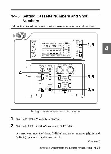
Chapter 4 Adjustments and Settings for Recording 4-37
4
4-5-5 Setting Cassette Numbers and ShotNumbers
Follow the procedure below to set a cassette number or shot number.
Setting a cassette number or shot number
1 Set the DISPLAY switch to DATA.
2 Set the DATA DISPLAY switch to SHOT-NO.
A cassette number (left-hand 3 digits) and a shot number (right-hand3 digits) appear in the display panel.
(Continued)
1,5
3,5
2,5
4
OFF
ON
DISPLAY
LIGHTRESET
HOLD
WARNINGCTLTC
DATA
ADVANCE
PRESET
F-RUNSET
DIAG
R-RUN
DATADISPLAY
NDFDF
REGEN
CLOCK
AUDIO INAUDIO SELECT
REAR
MIXCH-1 CH-2
FRONT
SHIFT
MANUALAUTO
LEVELCH-1••
••
•
• •
••
•
•
0 10
CH-2••
••
•
• •
••
•
•
CUE IN
0 10
U-BITSHOT TIME
NO.
H MIN SEC FRM
40
PEAK dB
OVER EMPH OVER
TAPE E B
VH
HOLDDIAG PB VITC NDF EXT-LK
RF SERVO HUMID SLACK
00:00:00:00
BATT E x x x x x x x
x x x x x x x
F
1 2
30
10
0
•
20

Chapter 4 Adjustments and Settings for Recording4-38
4
3 Set the F-RUN/SET/R-RUN switch to SET.
The rightmost digit of the shot number starts flashing.
4 Using the SHIFT and ADVANCE buttons, set the cassette numberor shot number (up to 999).SHIFT: Selects a digit to set. Each time you press this button, the
flashing digit moves one to the left.Pressing this button while holding down the HOLD buttonmoves the flashing digit one to the right.
ADVANCE: Increments the value of the flashing digit.Pressing this button while holding down the HOLD buttondecrements the value of the flashing digit.
To reset the cassette number or shot number to 001Select any digit of the cassette number or shot number, making itflash, then press the RESET button.
5 Return the DISPLAY, DATA DISPLAY and F-RUN/SET/R-RUNswitches to the original positions.

Chapter 4 Adjustments and Settings for Recording 4-39
4
4-6 Setup Menu Display onthe Viewfinder Screen
If the MENU ON/OFF/PAGE switch is set to ON, the setup menu isdisplayed on the viewfinder screen.Use this setup menu to select settings and also to select which items aredisplayed on the viewfinder screen as well as how they are displayed.
4-6-1 Setup Menu ConfigurationThe setup menu is displayed as individual pages. The pages that make upthe setup menu and brief details of the function of each page are listed inthe table below.You can change the configuration of the setup menu to suit yourrequirements. At the factory, the pages marked with the a) in the tableare available.
Pages and functions of the setup menu
a) At the factory, the setup menu consists of these pages.
Pagenumber
Page name Function Reference
1 a) MARKER1/3
Sets markers (centermarker and safety zonemarker).
Section 4-8-4 “Settingthe Marker Display”
2 MARKER2/3
Sets markers (boxcursor).
Maintenance Manual
3 MARKER3/3
Sets the output of themarkers
Maintenance Manual
4 a) VF DISP1/2
Selects the viewfinderscreen display, theextender display, andthe zoom positiondisplay.
Section 4-8-2“Selecting the DisplayItems”
(Continued)

Chapter 4 Adjustments and Settings for Recording4-40
4
Pagenumber
Page name Function Reference
5 a) VF DISP2/2
Viewfinder screendisplay selections (filter,white balance memory,and gain)
Section 4-8-2“Selecting the DisplayItems”
6 a) MASTERGAIN
Sets the GAIN selectorvalue.
Section 4-9-1“Setting the GAINSelector Values”
7 a) SHOT ID Sets the shot data ID. Section 4-8-6“Setting the Shot ID”
8 a) SHOT DISP. Selects the shot datadisplay.
Section 4-8-5“RecordingSuperimposed ShotData in Color Bars”
9 SHUTTER Sets the shutter speedand mode.
Section 4-2 “Settingthe Electronic Shutter”
10 ‘!’ LED Sets the operation ofthe indicator.
Section 4-7-2 “Settingthe Indicator”
11 a) SETUP CARD Accesses the setupcard.
Section 4-11 “Usingthe Setup Card”
12 FUNCTION1/2
Selects functions touse.
Maintenance Manual
13 FUNCTION2/2
Selects functions to use(continued).
Section 4-9-2“Selecting theFunctions”
14 WIDESCREEN(DVW-709WS/709WSP/790WS/790WSP only)
Selects the aspect ratio. Section 4-9-4“Selecting the AspectRatio”
a) At the factory, the setup menu consists of these pages.

Chapter 4 Adjustments and Settings for Recording 4-41
4
Pagenumber
Page name Function Reference
15 VF SETTING Selects viewfinderfunction.
Maintenance Manual
16 - 29 LEVEL 1 to 12 Adjust levels.
W-SHADINGG/R/B
30 to 32 Adjusts the whiteshading.
33 DCC ADJ. Adjusts the DCC.
34 OFFSETWHITE
Sets the offset for theAWB value.
35 PRESETWHITE
Sets the white presetvalue.
36 and37
OPERATION1-2
Use to make varioussettings.
38 FRMSHUTTER
Sets the optional flameshutter.
39 SG ADJ. Sets the SG.
40 ENC ADJ. Sets the ENC.
41 DATA-RESET Resets menu data.
Note
When the camcorder is connected to a remote control unit and is beingcontrolled remotely, the SHUTTER and several pages of the engineer-oriented menu (MEASUREMENT and DATA RESET pages) are notdisplayed. There are also some pages which are displayed but which youcannot use to change settings.For information about the function of each page, refer to the relevant sections inthis manual or “maintenance manual.”

Chapter 4 Adjustments and Settings for Recording4-42
4
When changing the setup menuYou can configure the setup menu to display only the pages you need.To select pages, use the MENU SELECT page of the engineer-orientedmenu. When using the engineer-oriented menu, switch the camcorder toengineer mode. Power off the camcorder, then hold down the rotaryencoder and turn the power on again.To revert to the user mode, turn the camcorder off and then on.
Engineer mode and user mode differ in the following ways.Engineer mode: All the pages in the setup menu can be used. Data set
with the menu is written to non-volatile memory and can be storedsemi-permanently.
User mode: Only the pages selected in the engineer mode MENUSELECT page can be used. Data set with the menu is written tonon-volatile memory and can be stored semi-permanently.
After making settings and adjustments in engineer mode, configure theCAMERAMAN menu on the MENU SELECT page with the pages youuse frequently so that you can access them quickly.Refer to “maintenance manual” for information about the MENU SELECT page.
For information about the CAMERAMAN menu settings, see section 4-9-7 “Settingthe CAMERAMAN menu” (page 4-95).

Chapter 4 Adjustments and Settings for Recording 4-43
4
MENU ON/OFF/PAGE switch MENU CANCEL/PRST/ITEM switch
Rotaryencoder
4-6-2 Basic Use of the Setup MenuUse the MENU ON/OFF/PAGE switch, the MENU CANCEL/PRST/ITEM switch, and the rotary encoder to manipulate the setup menu.
Controls for use of the setup menu
Follow the procedure below to use the setup menu.
1 Display the setup menu.
2 Select a page.
3 Select an item.
4 Change the setting of that item, or turn the function or display of thatitem on or off.
5 End the setup menu operation.

Chapter 4 Adjustments and Settings for Recording4-44
4
Initial page Next page Final page
Displaying the setup menuSet the MENU ON/OFF/PAGE switch to ON to display the setup menu.The status display along the top and bottom disappears from theviewfinder screen, and the page that was on the screen when the lastmenu operation ended appears.When this menu is first used, the lowest-numbered page of the currentlyselected pages for menu configuration appears. This also occurs if youset the MENU ON/OFF/PAGE switch to ON while holding the MENUCANCEL/PRST/ITEM switch at CANCEL.
Paging through the menuPush the MENU ON/OFF/PAGE switch from ON to PAGE.
Every time you push this switch to PAGE, the next page of the menu isdisplayed.
Paging through the menu
While a question mark appears at the left of the page title, you can usethe rotary encoder as follows to switch pages.Turning the rotary encoder counterclockwise as seen from the front
of the camera: advances to the next menu page.Turning the rotary encoder clockwise as seen from the front of the
camera: returns to the previous menu page.

Chapter 4 Adjustments and Settings for Recording 4-45
4
Cursor
Movement sequence
Selecting an itemPush the MENU CANCEL/PRST/ITEM switch to ITEM.Every time you push this switch to ITEM, the cursor (arrow), whichindicates the selected item, moves to the next item.
Cursor movement sequence
You can also use the rotary encoder as follows to switch items.While a question mark appears at the left of the page title, if you pressthe rotary encoder, the question mark disappears, and the cursor appears.Next turn the rotary encoder.Turning the rotary encoder counterclockwise as seen from the front
of the camera: moves the cursor up continuously.Turning the rotary encoder clockwise as seen from the front of the
camera: moves the cursor down continuously.
If you move the cursor to the left of the page title, and press the rotaryencoder, a question mark reappears at the left of the page title, and onceagain you can use the rotary encoder to change pages.
E01*MARKER 1/3 E01*MARKER 1/3 pSAFETY ZONE : ON SAFETY ZONE : ON SAFETY AREA : 90% SAFETY AREA : 90% CENTER : ON CENTER : ON CENTER H : 0 CENTER H : 0 CENTER V : 0 CENTER V : 0

Chapter 4 Adjustments and Settings for Recording4-46
4
Changing the setting of ON/OFF selection of aselected itemCheck that the cursor is by the desired item, then press the rotaryencoder. A question mark appears at the left of the setting value. Nextcarry out one of the following operations.
To increase a setting valueTurn the rotary encoder counterclockwise as seen from the front of thecamera.
To decrease a setting valueTurn the rotary encoder clockwise as seen from the front of the camera.
To toggle a setting on or offTo select the “ON” setting, turn the rotary encoder counterclockwise asseen from the front of the camera, and to select the “OFF” setting, turnthe rotary encoder clockwise.
Canceling the settings and resetting to the initial settingsYou can cancel the settings and reset them to their initial values (thoseset at the factory, or in engineer mode) by pushing the MENU CANCEL/PRST/ITEM switch to CANCEL/PRST.
When the MENU CANCEL/PRST/ITEM switch is pushed to CANCEL/PRST, the message “CANCEL?” appears below the page name. Tocancel the previous settings, push the switch to CANCEL/PRST again.To reset the settings to their initial values, push the switch to CANCEL/PRST a third time. The message “PRESET?” appears below the pagename. To reset to the initial settings, push the switch to CANCEL/PRSTonce more.

Chapter 4 Adjustments and Settings for Recording 4-47
4
The action of the CANCEL/PRST function differs for some settingitems. Some items are only affected by PRST; check the settingprocedure for each item for more information.
To confirm a settingPress the rotary encoder once more. The question mark at the left of thesetting value disappears, and you can again use the rotary encoder toselect items.
Closing the menuReturn the MENU ON/OFF/PAGE switch to OFF.The setup menu disappears from the viewfinder screen, and displaysshowing the current status of the camcorder appear along the top andbottom of the viewfinder screen.
When you close the switch coverWhen the cover for the MENU ON/OFF/PAGE and MENU CANCEL/PRST/ITEM switches is closed, the MENU ON/OFF/PAGE switch turnsoff automatically.

Chapter 4 Adjustments and Settings for Recording4-48
4
Viewfinder screen
REC indicator
Spare indicator
VTR SAVE indicator
TALLY indicator
indicator
4-7 Indicators in theViewfinder
The indicators of the status of the camcorder and the results ofadjustments are arranged along the top and bottom edges of theviewfinder screen.
4-7-1 Layout of Indicators in the ViewfinderThe indicators in the viewfinder are arranged as illustrated below.
Indicators in the viewfinder
1 TALLY indicatorThis lights when a green tally control signal is received from the cameracontrol unit and when the camcorder is in Loop Rec mode.The Loop Rec function is provided by the optional BKDW-703 extension board.For more details, see Section 3-2-3 “Starting a Shot with a Few Seconds of Pre-Stored Picture Data (Loop Rec Function) (When Using a BKDW-703 ExtensionBoard)”(page 3-12).
1
2
3
4
5
6
BATTTALLY/REC
VTRSAVE
BATT indicator

Chapter 4 Adjustments and Settings for Recording 4-49
4
2 REC (recording) indicatorThis indicator lights in red during recording. It also warns by flashing.This lamp also lights when RED TALLY control signal is sent from thecamera control unit.For more information, see Section 6-3 “Operating Warnings” (page 6-12).
3 BATT (battery) indicatorThis indicator starts to flash when the voltage of the battery connected tothe camcorder has fallen. This indicator stays on for a few minutes whenthe battery is dead.To prevent any interruption in operation, change the battery as soon as itgets low.For more information, see Section 5-1-4 “Avoiding Breaks in Operation Due toDead Batteries” (page 5-7).
4 (operation status warning) indicatorThis indicator lights when the camcorder is used under one or more ofthe following conditions and if the corresponding items have been set toON in the ‘!’ LED page of the setup menu.• The gain is set to anything but 0 dB.• The SHUTTER selector is ON.• The WHITE BAL switch is at PRST.• ATW is being used.• The lens extender is in use.• The FILTER selector is set to anything but 1 (DVW-707/707P).• The FILTER selector is set to anything but ND:1/CC:B.
(DVW-709WS/709WSP/790WS/790WSP only).• The reference value of the automatic iris adjustment is anything but the
standard value.See Section 4-7-2 “Setting the Indicator” (page 4-50) for more informationabout selecting the items that will cause the indicator to operate.
5 Spare indicatorThis is a spare indicator. A setup menu operation makes it possible to usethis as a REC indicator.

Chapter 4 Adjustments and Settings for Recording4-50
4
For more information about the use of this spare indicator, refer to “maintenancemanual.”
6 VTR SAVE indicatorThis indicator lights when the VTR SAVE/STBY switch is set to SAVE.This indicator goes off during recording.
4-7-2 Setting the IndicatorSelect the items to be indicated by the indicator from the ‘!’ LEDpage of the setup menu. Note that at the factory the ‘!’ page is not set fordisplay. To access the ‘!’ LED page, either set the camcorder to engineermode, or select the ‘!’ LED page from the MENU SELECT page beforeuse.See Section 4-6-1 “Setup Menu Configuration” (page 4-39) for more informationabout the engineer mode and selecting the display page.
Follow the procedure below to set the indicator.
Setting the indicator
1 Set the MENU ON/OFF/PAGE switch to ON.
1,2,6
2,4,5
3

Chapter 4 Adjustments and Settings for Recording 4-51
4Select whether the indicator is to light for each of the following itemconditions.
When the WHITE BAL switch is at PRST
When the SHUTTER selector is at ON
When the FILTER selector is set to anything but 1
When the lens extender is in use
When the ATW function is working
The display for setting the status disappears from the viewfinderscreen, and the page that was on the screen when the last menuoperation ended appears.(When this menu is first used, the lowest-numbered page of the currently selected pages for configuring themenu appears.)
2 Push the MENU ON/OFF/PAGE switch repeatedly to PAGE untilthe ‘!’ LED page shown below appears (or use the rotary encoder).
‘!’ LED page (factory settings)
3 Push the MENU CANCEL/PRST/ITEM switch repeatedly to ITEMuntil the cursor reaches the desired item (or use the rotary encoder).
(When the CC filter selector is set toanything but ND:1/CC:B) 1)
When the gain is set to anything but 0 dB
When the reference value of theautomatic iris adjustment is anythingbut the standard value
1) DVW-709WS/709WSP/790WS/790WSP only
?E10*! LED ?E10*! LED GAIN : ON GAIN : ON SHUTTER ON : ON SHUTTER ON : ON WHITE PRESET : OFF WHITE PRESET : OFF ATW RUN : OFF ATW RUN : OFF EXTENDER ON : ON EXTENDER ON : ON FILTER 2,3,4 : OFF FILTER 2,3,4 : OFF FILTER A,C,D : OFF FILTER A,C,D : OFF A.IRIS OVERRIDE: OFF A.IRIS OVERRIDE: OFF
(Continued)

Chapter 4 Adjustments and Settings for Recording4-52
4
4 Turn the rotary encoder to select whether the indicator shouldlight with respect to the selected item (the “ON” setting), or not light(the “OFF” setting).For the “ON” setting: Press the rotary encoder, and when a
question mark appears to the left of the “ON/OFF” indication,turn the rotary encoder counterclockwise as seen from the frontof the camera. The “ON/OFF” indication switches to “ON”.
For the “OFF” setting: Press the rotary encoder, and when aquestion mark appears to the left of the “ON/OFF” indication,turn the rotary encoder clockwise as seen from the front of thecamera. The “ON/OFF” indication switches to “OFF”.
To turn the setting of another item ON or OFF, repeat steps 3 and 4.
5 Press the rotary encoder to make the question mark to the left of the“ON/OFF” indication disappear.
6 To end the menu operation, return the MENU ON/OFF/PAGEswitch to OFF.
The setup menu disappears from the viewfinder screen and thedisplays indicating the current status of the camcorder appear alongthe top and bottom of the viewfinder.

Chapter 4 Adjustments and Settings for Recording 4-53
4
4-8 Status Display on theViewfinder Screen
The viewfinder screen displays not only the video picture but alsocharacters and messages indicating the camcorder settings and operatingstatus, a center marker, a safety zone marker, etc.When the MENU ON/OFF/PAGE switch is set to OFF, and theviewfinder DISPLAY switch is set to ON, the items for which an “ON”setting was made in the VF DISP page of the setup menu or with relatedswitches are displayed at the top and bottom of the screen. The messagesthat give details of the settings and adjustment progress and results canalso be made to appear for about 3 seconds while settings are beingchanged, during adjustment, and after adjustment.For information about the display item selection, see Section 4-8-2 “Selecting theDisplay Items” (page 4-58); for information about setting change and adjustmentprogress messages, see Section 4-8-3 “Display Mode and Setting Change andAdjustment Progress Messages” (page 4-61); and for information about markerdisplay, see Section 4-8-4 “Setting the Marker Display” (page 4-64).
Note
When the setup menu is displayed using the MENU ON/OFF/PAGEswitch, no superimposed information on the camera settings (e.g. whitebalance) appears on the viewfinder screen.

Chapter 4 Adjustments and Settings for Recording4-54
4
3, 4, 7, qk, ql and w; appear only when color bars are displayed.
Setting change and adjustmentprogress message display area(For more information, see Section4-8-3 “Display Mode and SettingChange and Adjustment ProgressMessages (page 4-61).)
4-8-1 Layout of the Status Display on theViewfinder Screen
All items that can be displayed on the viewfinder screen are shownbelow.
Status display on the viewfinder screen
1 Extender indicatorThis indicator appears when a lens extender is used.
2 Zoom position indicator 1)
This indicator indicates the approximate position of the variator 2) of thezoom lens, between wide angle (W) and telephoto (T).
3 Cassette number indicatorThis shows the cassette number.
....................................................................................................................................1) Zoom position indicator
This indicator appears only when you use a lens that has a zoom position displayfunction.
2) VariatorA group of lenses that are moved to adjust the focal length.
1 2 3 4 5
qh
qj
qk7
qa
6w;
qg qsqfqd 0 9 8
ql
EX W T S:001C:001 90%
1A W:A 9dB 1/1000 F-25 F5.6
CAM? CAM? ENW/ 71000 VTR? ENW/ 71000 VTR? 95/01/01 12:10 95/01/01 12:10 SHOT ID (1-4) SHOT ID (1-4) FUNCTION MSG 16:9 FUNCTION MSG 16:9 ERROR MSG ERROR MSG CG 00:00:00:00 CG 00:00:00:00 16:9 LOW LLCdT16:9 LOW LLCdT
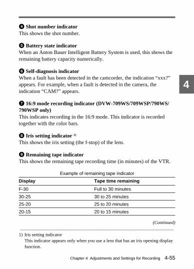
Chapter 4 Adjustments and Settings for Recording 4-55
4
4 Shot number indicatorThis shows the shot number.
5 Battery state indicatorWhen an Anton Bauer Intelligent Battery System is used, this shows theremaining battery capacity numerically.
6 Self-diagnosis indicatorWhen a fault has been detected in the camcorder, the indication “xxx?”appears. For example, when a fault is detected in the camera, theindication “CAM?” appears.
7 16:9 mode recording indicator (DVW-709WS/709WSP/790WS/790WSP only)This indicates recording in the 16:9 mode. This indicator is recordedtogether with the color bars.
8 Iris setting indicator 1)
This shows the iris setting (the f-stop) of the lens.
9 Remaining tape indicatorThis shows the remaining tape recording time (in minutes) of the VTR.
Example of remaining tape indicator
Display Tape time remaining
F-30 Full to 30 minutes
30-25 30 to 25 minutes
25-20 25 to 20 minutes
20-15 20 to 15 minutes
....................................................................................................................................1) Iris setting indicator
This indicator appears only when you use a lens that has an iris opening displayfunction.
(Continued)

Chapter 4 Adjustments and Settings for Recording4-56
4
Example of remaining tape indicator
Display Tape time remaining
15-10 15 to 10 minutes
10-5 10 to 5 minutes
5-0 5 to 2 minutes
5-0 (flashing) Less than 2 minutes
q; Audio level indicatorThis indicator indicates the level of the audio channel selected by themonitor switch.This indicator roughly corresponds to the peak indication of the levelmeter of the internal VTR of a sine wave input as follows:
Audio level indicator
For information about turning the audio level indicator on and off, see Section 4-4“Adjusting the Audio Level” (page 4-24).
qa Subject illumination indicatorThis appears, depending on the setting, to indicate that the subjectillumination is inadequate.
qs Shutter speed and mode indicatorThis indicator indicates the shutter speed and mode settings.
Level indicator of audiochannel selected by themonitor switch
VTR level meter
|–40
|–30
|–20
|–17
|–14
(dB)
|–26
|–23

Chapter 4 Adjustments and Settings for Recording 4-57
4
1/100 (DVW-707/709WS/790WS) or 1/60 (DVW-707P/709WSP/790WSP), 1/125,1/250, 1/500, 1/1000, 1/2000: Shutter speed (in seconds) in standardmode.
CLS: CLS modeECS: ECS mode (DVW-790WS/790WSP only)EVS: EVS mode
qd Gain indicatorThis indicator indicates the gain (in dB) of the video amplifier, as set bythe GAIN selector.
qf White balance memory indicatorThis indicator indicates the currently selected white balance automaticadjustment memory.A: The WHITE BAL switch is set to A.B: The WHITE BAL switch is set to B.P: The WHITE BAL switch is set to PRST or when the preset button on
the RM-B150 has been pushed.M: The WHITE BAL switch of the RM-P9 Remote Control Unit is set to
MANUAL.T: ATW is being used.
qg Filter indicatorThis indicator indicates the currently selected filter types.
qh 16:9 mode indicator (DVW-709WS/709WSP/790WS/790WSPonly)This indicates the 16:9 mode.
qj Time code indicatorThis indicates the time code, user bits or other information selected bythe DISPLAY switch and DATA DISPLAY switch settings.For more information, see the section “Relationships between the DISPLAY switchand DATA DISPLAY switch settings and the time counter displays” (page 2-41).

Chapter 4 Adjustments and Settings for Recording4-58
4
qk ID number indicatorThis indicates the ID number selected from ID1 to ID4. This indicator isrecorded together with the color bars.
ql Date and time indicatorThis shows the date and time of recording. This indicator is recordedtogether with the color bars
w; Model name and serial number indicatorThis displays the model name and serial number of the camcorder. Thisindicator is recorded together with the color bars.
4-8-2 Selecting the Display ItemsTo select the items to be displayed on the viewfinder screen from the VFDISP page, turn on or off the indication next to each item. Selection ofthe following items can be turned on or off on the VF DISP 1/2 and 2/2pages.• Display mode (For more information, see Section 4-8-3 “Display
Mode and Setting Change and Adjustment Progress Messages” (page4-61).)
• Extender indicator• Zoom position indicator• Filter indicator• White balance memory indicator• Gain indicator• Shutter speed and mode indicator• Remaining tape indicator• Iris opening indicator
Selecting the display itemsFollow the procedure below to select the items to be displayed on theviewfinder screen.

Chapter 4 Adjustments and Settings for Recording 4-59
4
(Continued)
Zoom position indicator
Extender indicator
Display mode
Selecting the display items
1 Set the MENU ON/OFF/PAGE switch to ON.
The page that was on the screen when the last menu operation endedappears on the viewfinder screen. (When this menu is first used, thelowest-numbered one of the currently selected pages appears).
2 Push the MENU ON/OFF/PAGE switch repeatedly to PAGE untilthe VF DISP 1/2 or 2/2 page shown below appears (or use the rotaryencoder).
VF DISP 1/2 page (factory settings)
1,2,5
4
3
?E04*VF DISP 1/2 ?E04*VF DISP 1/2
DISP MODE : 3 DISP MODE : 3
EXTENDER : ON EXTENDER : ON
ZOOM : ON ZOOM : ON

Chapter 4 Adjustments and Settings for Recording4-60
4VF DISP 2/2 page (factory settings)
3 Push the MENU CANCEL/PRST/ITEM switch repeatedly to ITEMuntil the cursor reaches the desired item (or use the rotary encoder).
4 Turn the rotary encoder to select whether the selected item shouldappear in the viewfinder display (the “ON” setting), or not appear(the “OFF” setting).
Note that pushing the MENU CANCEL/PRST/ITEM switch toCANCEL/PRST on this page has no effect.
To turn the setting of another item ON or OFF, repeat steps 3 and 4.
5 To end the menu operation, return the MENU ON/OFF/PAGEswitch to OFF.
The setup menu disappears from the viewfinder screen and thedisplay indicating the current status of the camcorder appears alongthe top and bottom of the viewfinder screen (when the viewfinderDISPLAY switch is set to ON).
Filter indicator
White balance memory indicator
Gain indicator
Shutter speed/mode indicator
Remaining tape indicator
Iris opening indicator
Monitor audio level indicator
?E05*VF DISP 2/2 ?E05*VF DISP 2/2
FILTER : ON FILTER : ON
WHITE : ON WHITE : ON
GAIN : ON GAIN : ON
SHUTTER : ON SHUTTER : ON
AUDIO : ON AUDIO : ON
TAPE : ON TAPE : ON
IRIS : ON IRIS : ON

Chapter 4 Adjustments and Settings for Recording 4-61
4
4-8-3 Display Mode and Setting Change andAdjustment Progress Messages
You can limit or suppress the messages that give details of settingchanges and adjustment progress and results by setting a display mode.The conditions under which messages are displayed and theircorrespondence with the display mode are as follows:
Setting change and adjustment progress messages and display modes
Y: Message is displayed.N: Message is not displayed.
Message displaycondition
Message Display modesetting
1 2 3
When the filter selectionhas been changed
FILTER : n (where n = 1, 2, 3,4)
N N Y
When the gain settinghas been changed
GAIN : n (where n = –3dB,0dB, 3dB, 6dB, 9dB,12dB,18dB, 24dB, 30dB, 36dB,42dB, 48dB)
N N Y
When the setting of theWHITE BAL switch hasbeen changed
WHITE : n (where n = A CH,B CH, PRST) or ATW : RUN
N N Y
When the OUTPUT/DCC selector has beenset to DCC ON or OFF
DCC : ON (or OFF) N Y Y
(Continued)

Chapter 4 Adjustments and Settings for Recording4-62
4
Setting change and adjustment progress messages and display modes
Y: Message is displayed.N: Message is not displayed.
Message displaycondition
Message Display modesetting
1 2 3
When the shutter speedand mode setting hasbeen changed a)
: SS : 1/100 (DVW-707/709WS/790WS) or 1/60(DVW-707P/709WSP/790WSP) (or 1/125, 1/250,1/500, 1/1000,1/2000, CLS, ECS b), EVS)
N Y Y
When the black or whitebalance has beenadjusted
E.g. WHITE : OK
For more informarion, seeSection 4-1 “Adjusting the BlackBalance and the White Balance”(page 4-1).
N Y Y
a) This is also displayed for about 3 seconds when the SHUTTER selector is set toON.
b) DVW-790WS/790WSP only

Chapter 4 Adjustments and Settings for Recording 4-63
4
Changing the display modeThe currently set display mode appears on the VF DISP page of the setupmenu. Follow the procedure below to change it.
Changing the display mode
1 Follow steps 1 to 3 in Section 4-8-2 “Selecting the Display Items”(page 4-58), until the VF DISP 1/2 page of the setup menu is on theviewfinder screen and the cursor is at DISP MODE.
2 Press the rotary encoder so that a question mark appears to the left ofthe display mode indication, then turn the rotary encoder to changethe display mode selection.
3 When the setting is completed, press the rotary encoder.
The question mark to the left of the display mode indicationdisappears.
4 To end the menu operation, set the MENU ON/OFF/PAGE switch toOFF.
1,4
2,3
1

Chapter 4 Adjustments and Settings for Recording4-64
4
4-8-4 Setting the Marker DisplayUse the MARKER 1/3 page of the setup menu to switch the display ofthe center and safety zone markers on or off and to select whether thearea indicated by the safety zone marker is 80%, 90% or 100% of thescreen area.
Setting the marker displayFollow the procedure below to set details of the marker display.
Setting the marker display
1 Set the MENU ON/OFF/PAGE switch to ON.
The page that was on the screen when the last menu operation endedappears on the viewfinder screen. (When this menu is first used, thelowest-numbered one of the currently selected pages appears.)
2 Push the MENU ON/OFF/PAGE switch repeatedly to PAGE untilthe MARKER 1/3 page shown on the next page appears (or use therotary encoder).
1,2,5
4
3

Chapter 4 Adjustments and Settings for Recording 4-65
4Setting of display position of centermarker (vertical)
Setting of display position of centermarker (horizontal)
ON/OFF of center marker indicator
Safety zone area setting
ON/OFF of safety zone marker indicator
MARKER 1/3 page (factory settings)
3 Push the MENU CANCEL/PRST/ITEM switch repeatedly to ITEMuntil the cursor reaches the desired item (or use the rotary encoder).
4 For each item, operate the rotary encoder as follows (directionsindicated as seen from the front of the camera).CENTER or SAFETY ZONE selections: For an “ON” display
setting, turn the rotary encoder counterclockwise; for an “OFF”display setting, turn the rotary encoder clockwise.
SAFETY AREA selection: To set the safety zone to 100% of thescreen area, turn the rotary encoder counterclockwise, and to setthe safety zone to 80% of the screen area, turn the rotaryencoder clockwise.
CENTER H selection: To move the center marker to the right inthe viewfinder, turn the rotary encoder counterclockwise, and tomove the center marker to the left in the viewfinder, turn therotary encoder clockwise.
CENTER V selection: To move the center marker up in theviewfinder, turn the rotary encoder counterclockwise, and tomove the center marker down in the viewfinder, turn the rotaryencoder clockwise.
E01*MARKER 1/3 pSAFETY ZONE : ON SAFETY AREA : 90% CENTER : ON CENTER H : 0 CENTER V : 0
(Continued)

Chapter 4 Adjustments and Settings for Recording4-66
4
If any of the above selections is set to ON, the corresponding markeris displayed.
Note that the CANCEL and PRESET functions can also be used forthe CENTER H and CENTER V selections.If the MENU CANCEL/PRST/ITEM switch is pressed twice toCANCEL/PRST, all the previous settings are canceled. If the switchis pressed twice more to CANCEL/PRST, the settings are reset totheir initial values.
5 To end the menu operation, return the MENU ON/OFF/PAGEswitch to OFF.
The setup menu disappears from the viewfinder screen and thedisplays indicating the current status of the camcorder appear alongthe top and bottom of the viewfinder.
4-8-5 Recording Superimposed Shot Data inColor Bars
In the setup menu SHOT DISP. page, you can select which shot data isrecorded superimposed on the color bars. You can also select which ofthe shot IDs (1 to 4) set in the SHOT DATA page is recordedsuperimposed on the picture.

Chapter 4 Adjustments and Settings for Recording 4-67
4
Use the following procedure.
Selecting the shot data for superimposed recording
1 Set the MENU ON/OFF/PAGE switch to ON.
The last page accessed appears in the viewfinder display (initiallythe SHOT DATA page appears).
2 Press the MENU ON/OFF/PAGE switch repeatedly toward thePAGE position (or use the rotary encoder) until the SHOT DISP.page appears, as shown below.
1,2,6
4
3,5
?E08*SHOT DISP. ?E08*SHOT DISP.
DATE : OFF DATE : OFF
TIME : OFF TIME : OFF
MODEL NAME : OFF MODEL NAME : OFF
SERIAL NO. : OFF SERIAL NO. : OFF
CASSETTE NO. : OFF CASSETTE NO. : OFF
SHOT NO. : OFF SHOT NO. : OFF
ID SELECT ; OFF ID SELECT ; OFF
(Continued)

Chapter 4 Adjustments and Settings for Recording4-68
4
3 Push the MENU CANCEL/PRST/ITEM switch repeatedly towardthe ITEM position until the cursor is positioned to the left of theitem you wish to set (or use the rotary encoder).
The items and their meanings are as follows:DATE: dateTIME: timeMODEL NAME: model nameSERIAL NO.: serial numberCASSETTE NO.: cassette numberSHOT NO.: shot numberID SELECT: shot ID set in SHOT DATA page
Next press the rotary encoder so that a question mark appears to theleft of the selected item.
4 Turn the rotary encoder to select whether or not to record theselected item superimposed on the picture.
To carry out superimposed recording: turn the rotary encodercounterclockwise as seen from the front of the camera to select“ON”.
Not to carry out superimposed recording: turn the rotary encoderclockwise as seen from the front of the camera to select “OFF”.
In the ID SELECT item, in order not to carry out superimposedrecording of any shot ID, select “OFF”, and to carry outsuperimposed recording of a shot ID, select the shot ID number (1 to4).
To set other items on or off, continue to step 5. If all item settingsare complete, skip to step 6 to end the process.

Chapter 4 Adjustments and Settings for Recording 4-69
4
5 Press the MENU CANCEL/PRST/ITEM switch toward the ITEMposition (or use the rotary encoder), to advance the cursor to the nextposition, then return to step 4 to make the next on/off setting.
6 To exit from the menu, return the MENU ON/OFF/PAGE switch tothe OFF position.
The setup menu disappears from the viewfinder screen.
To carry out superimposed recordingTo actually record the items selected for superimposed recording in theSHOT DISP. page, set the OUTPUT/DCC switch to BARS, DCC OFF.The items selected for superimposed recording appear in the viewfinderscreen and are recorded superimposed on the picture.
4-8-6 Setting the Shot IDIn the SHOT ID page of the setup menu, you can set a shot ID, of up to12 alphanumeric characters, spaces, and symbols.When the OUTPUT/DCC switch is set to BARS, DCC OFF, this shot IDis output with the color bar signal. The shot ID comprises ID1 to ID4,and the setting can be changed using the SHOT DISP. page of the setupmenu.
Notes
• To display the shot ID, set the TEST OUT item in the FUNCTION 1/2page of the setup menu to ENC, and make the signal output from theTEST OUT connector a composite signal.For information about the TEST OUT page, see Section 4-9-3 “Selecting the TestOutput” (page 4-83).
• When the setup menu is displayed, the shot ID is not displayed even ifthe color bar signal is output.

Chapter 4 Adjustments and Settings for Recording4-70
4
Setting the shot IDFollow the procedure below to set the shot ID.
Setting the shot ID
1 Set the MENU ON/OFF/PAGE switch to ON.
The page that was on the screen when the last menu operation endedappears on the viewfinder screen. (When this menu is first used, thelowest-numbered page of the currently selected pages forconfiguring the menu appears).
2 Push the MENU ON/OFF/PAGE switch repeatedly to PAGE untilthe SHOT ID page shown below appears (or use the rotary encoder).
Shot ID(Squares indicate spaces;they are displayed this wayonly on this menu page.)
1,2,7
4,5,6
3,5
?E07*SHOT ID ?E07*SHOT ID
o o ID-1 :ABC- ID-1 :ABC-
ID-2 : ID-2 :
ID-3 : ID-3 :
ID-4 : ID-4 :

Chapter 4 Adjustments and Settings for Recording 4-71
4
3 Press the MENU CANCEL/PRST/ITEM switch repeatedly towardthe ITEM position, until the ID (one of ID-1 to ID-4) you wish to sethas the cursor to the left of it (or use the rotary encoder).
When you press the rotary encoder once more, a question markappears by the selected ID, and a character position selection cursor(Ø) also appears (the character setting mode).
4 Press the rotary encoder repeatedly until the character positioncursor indicates the character you wish to set.
Each time you press the rotary encoder, the cursor moves oneposition to the right. If you press it when the cursor is at the rightend, the cursor disappears, the camcorder exits from the charactersetting mode.
5 Turn the rotary encoder until the character you wish to set appears.
Turn the rotary encoder clockwise as seen from the front of thecamera to cycle the character from the alphabet, through space (s),the symbols, and the digits, in that order. Turn the rotary encodercounterclockwise to cycle through the characters in the reversedirection.
It is also possible to enter a space when the character position cursor(Ø) is in the required character position, by pressing the MENUCANCEL/PRST/ITEM switch toward the CANCEL/PRST position.
To set more characters, go to step 6, and to end character setting go tostep 7.
6 Press the rotary encoder to advance the character position cursor tothe next position, then return to step 5 to set a character.

Chapter 4 Adjustments and Settings for Recording4-72
4
7 To end the menu operation, return the MENU ON/OFF/PAGEswitch to OFF.
The setup menu disappears from the viewfinder screen and thedisplays indicating the current status of the camcorder appear alongthe top and bottom of the viewfinder.
Deleting a characterFollow the procedure below.
Deleting a character
1 Move the cursor (↓) to the position of the character to be deleted.
1
2,3
?E07*SHOT ID o ID-1 :ABC- ID-2 : ID-3 : ID-4 :
?E07*SHOT ID o ID-1 : BC- ID-2 : ID-3 : ID-4 :

Chapter 4 Adjustments and Settings for Recording 4-73
4
2 Press the MENU CANCEL/PRST/ITEM switch to CANCEL/PRST.
The character below the character position cursor disappears, and isreplaced by a space (s).
3 (1) To delete another character, press the rotary encoder repeatedlyuntil the cursor is at the position of the character to be deleted.
(2) Return to step 2 to delete the character.
4-8-7 Displaying Time Code and OtherInformation
In the setup menu OPERATION 2 page, you can select information to bedisplayed in the viewfinder and output from the TEST OUT connector.Use the following procedure.
Settings to select whether or not to display or output time code and so forth
1 Set the MENU ON/OFF/PAGE switch to ON.
The last page accessed appears in the viewfinder display. When thismenu is first used, the lowest-numbered on of the currently selectedpages appears.
1,2,5
4
3
(Continued)

Chapter 4 Adjustments and Settings for Recording4-74
4
2 Press the MENU ON/OFF/PAGE switch toward the PAGE position(or use the rotary encoder) until the OPERATION 2 page appears, asshown below.
3 Push the MENU CANCEL/PRST/ITEM switch toward the ITEMposition.
Next press the rotary encoder, to display a question mark to the leftof “TIME CODE DISP”.
4 Turn the rotary encoder to select whether or not to display or outputthe time code and other information.
To display or output the information: turn the rotary encodercounterclockwise as seen from the front of the camera to selectone of the following settings.• VF: display in the viewfinder.• TEST: output from the TEST OUT connector.• BOTH: display in the viewfinder and output from the TEST
OUT connector.To neither display nor output the information: turn the rotary
encoder clockwise as seen from the front of the camera to select“OFF”.
5 To exit from the menu, return the MENU ON/OFF/PAGE switch toOFF.
E37*OPERATION 2 E37*OPERATION 2
AWB LEVEL GATE : ON AWB LEVEL GATE : ON
COLOR VF : COMP COLOR VF : COMP
REC TALLY : UPPER REC TALLY : UPPER
pTIME CODE DISP : OFFTIME CODE DISP : OFF

Chapter 4 Adjustments and Settings for Recording 4-75
4
The set up menu disappears from the viewfinder screen and the displaysindicating the current status of the camcorder appear along the top andbottom of the viewfinder screen.
Selecting information to displayUse the DISPLAY and DATA DISPLAY switches to select theinformation to display from the following.• time code• CTL• user bits• shot data date and time• cassette number and shot number from shot dataFor details, see the section “Time code displays” (page 2-40).
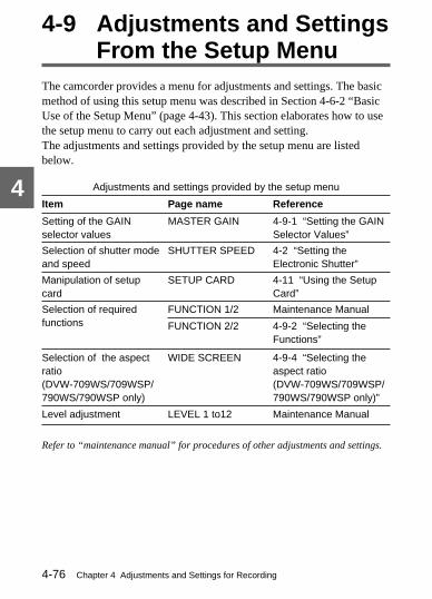
Chapter 4 Adjustments and Settings for Recording4-76
4
4-9 Adjustments and SettingsFrom the Setup Menu
The camcorder provides a menu for adjustments and settings. The basicmethod of using this setup menu was described in Section 4-6-2 “BasicUse of the Setup Menu” (page 4-43). This section elaborates how to usethe setup menu to carry out each adjustment and setting.The adjustments and settings provided by the setup menu are listedbelow.
Adjustments and settings provided by the setup menu
Item Page name Reference
Setting of the GAINselector values
MASTER GAIN 4-9-1 “Setting the GAINSelector Values”
Selection of shutter modeand speed
SHUTTER SPEED 4-2 “Setting theElectronic Shutter”
Manipulation of setupcard
SETUP CARD 4-11 “Using the SetupCard”
Selection of requiredfunctions
FUNCTION 1/2 Maintenance Manual
FUNCTION 2/2 4-9-2 “Selecting theFunctions”
Selection of the aspectratio(DVW-709WS/709WSP/790WS/790WSP only)
WIDE SCREEN 4-9-4 “Selecting theaspect ratio(DVW-709WS/709WSP/790WS/790WSP only)”
Refer to “maintenance manual” for procedures of other adjustments and settings.
Level adjustment LEVEL 1 to12 Maintenance Manual

Chapter 4 Adjustments and Settings for Recording 4-77
4
4-9-1 Setting the GAIN Selector ValuesBefore using the camcorder, use the MASTER GAIN page of the setupmenu to set the gains corresponding to the L, M, and H positions of theGAIN selector and the TURBO GAIN switch, which switches the gainof the video amplifier.
Setting the GAIN selector valuesFollow the procedure below to set a gain value for each switch position.
Setting the GAIN selector values
1 Set the MENU ON/OFF/PAGE switch to ON.
The page that was on the screen when the last menu operation endedappears on the viewfinder screen. (When this menu is first used, thelowest-numbered one of the currently selected pages appears.)
2 Push the MENU ON/OFF/PAGE switch repeatedly to PAGE untilthe MASTER GAIN page shown on the next page appears (or usethe rotary encoder).
1,2,7
4,5,6
3
(Continued)
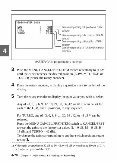
Chapter 4 Adjustments and Settings for Recording4-78
4
MASTER GAIN page (factory settings)
3 Push the MENU CANCEL/PRST/ITEM switch repeatedly to ITEMuntil the cursor reaches the desired position (LOW, MID, HIGH orTURBO) (or use the rotary encoder).
4 Press the rotary encoder, to display a question mark to the left of thedisplay.
5 Turn the rotary encoder to display the gain value you wish to select.
Any of –3, 0, 3, 6, 9, 12, 18, 24, 30, 36, 42, or 48 dB can be set foreach of the L, M, and H positions, in any sequence.
For TURBO, any of –3, 0, 3, 6, ..., 30, 36 , 42, or 48 dB 1) can beselected.Press the MENU CANCEL/PRST/ITEM switch to CANCEL/PRSTto reset the gains to the factory set values (L = 0 dB, M = 9 dB, H =18 dB, and TURBO = 42 dB).To change the gain corresponding to another switch position, returnto step 3.
Gain corresponding to L position of GAINselector
Gain corresponding to M position of GAINselector
Gain corresponding to TURBO GAIN buttonselection
Gain corresponding to H position of GAINselector
....................................................................................................................................1) Video gain boosted from 30 dB to 36, 42, or 48 dB by combining blocks of 2, 4,
or 8 adjacent pixels of the CCD.
?E06*MASTER GAIN
LOW : 0dB
MID : 9dB
HIGH : 18dB
TURBO : 42dB

Chapter 4 Adjustments and Settings for Recording 4-79
4
If the settings of the GAIN selector values have been changed, theblack set must also be adjusted.For more information, refer to “maintenance manual.”
6 Press the rotary encoder, so that the question mark disappears.
7 To end the menu operation, set the MENU ON/OFF/PAGE switch toOFF.
The setup menu disappears from the viewfinder screen and thedisplays indicating the current status of the camcorder appear alongthe top and bottom of the viewfinder.
4-9-2 Selecting the FunctionsUse the FUNCTION 2/2 page of the setup menu to select the camcorderfunctions related to return video signal.
Selecting required functionsFollow the procedure below to select the required functions.
Selecting required functions
1,2,7
4,5,6
3
(Continued)
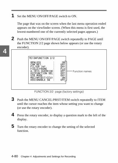
Chapter 4 Adjustments and Settings for Recording4-80
4
1 Set the MENU ON/OFF/PAGE switch to ON.
The page that was on the screen when the last menu operation endedappears on the viewfinder screen. (When this menu is first used, thelowest-numbered one of the currently selected pages appears.)
2 Push the MENU ON/OFF/PAGE switch repeatedly to PAGE untilthe FUNCTION 2/2 page shown below appears (or use the rotaryencoder).
FUNCTION 2/2 page (factory settings)
3 Push the MENU CANCEL/PRST/ITEM switch repeatedly to ITEMuntil the cursor reaches the item whose setting you want to change(or use the rotary encoder).
4 Press the rotary encoder, to display a question mark to the left of thedisplay.
5 Turn the rotary encoder to change the setting of the selectedfunction.
Function names
?E13*FUNCTION 2/2 ?E13*FUNCTION 2/2
GENLOCK : ON GENLOCK : ON
CAM RET. : OFF CAM RET. : OFF
FILTER INT. : OFF FILTER INT. : OFF
FIELD/FRAME : FLD FIELD/FRAME : FLD
A.IRIS OVERRIDE: OFF A.IRIS OVERRIDE: OFF
DCCFUNCTION SEL: OFF DCCFUNCTION SEL: OFF
VTR MODE VTR MODE : OFF : OFF
RECINHIBIT(CCU): ON RECINHIBIT(CCU): ON
ASSIGNABLE SW : OFF ASSIGNABLE SW : OFF

Chapter 4 Adjustments and Settings for Recording 4-81
4
GENLOCK: To use the signal input to the GENLOCK INconnector as a camera genlock signal or for an external timecode lock (the “ON” setting), turn the rotary encodercounterclockwise as seen from the front of the camera, and inorder not to use it (the “OFF” setting), turn the rotary encoderclockwise.
CAM RET.: To display the return video signal input to theGENLOCK IN connector on the viewfinder screen by using theRET button on the lens (the “ON” setting), turn the rotaryencoder counterclockwise as seen from the front of the camera,and in order not to display it (the “OFF” setting), turn the rotaryencoder clockwise.
FILTER INH.: To restrict the number of white balance memoriesto one each for A and B (the “ON” setting), turn the rotaryencoder counterclockwise as seen from the front of the camera,and in order not to restrict the number in this way (the “OFF”setting), turn the rotary encoder clockwise.
FIELD/FRAME: Switches between field (FLD) and frame (FRM)for the method of charge accumulation of the CCD sensor.For details of menu operation, refer to “maintenance manual.”
A. IRIS OVERRIDE: To make fine adjustment of the referencevalue for automatic iris adjustment (the “ON” setting), turn therotary encoder counterclockwise as seen from the front of thecamera, and in order not to make fine adjustment (the “OFF”setting), turn the rotary encoder clockwise.See Section 4-3 “Changing the Reference Value for Automatic IrisAdjustment” (page 4-21) for more information about fine adjustment ofthe reference value of the automatic iris adjustment.
(Continued)

Chapter 4 Adjustments and Settings for Recording4-82
4
DCC FUNCTION SEL: Specifies either the activation of the DCC ora knee fixed at D Range 600% when the DCC is selected. SelectFIX if you don’t want too sharp a change in image contrast.
VTR MODE: Enables the REC switch on the camcorder and theREC switch on an external VTR to function independentlywhen the camcorder is connected to the external VTR via theTRIAX connector on a CA-702/702P.
REC INHIBIT (CCU): The VTR section on the camcorder and the 5-inch viewfinder (or color viewfinder) cannot be used while thecamcorder is connected to a camera control unit via the TRIAXconnector on a CA-755. If you are using a 5-inch viewfinder (orcolor viewfinder), turn REC INHIBIT (CCU) to ON. If you wantto record using the VTR section, turn the REC INHIBIT (CCU) toOFF.
Note
When the camera control unit is connected to the camcorder, theplayback and rec review functions cannot be used.
ASSIGNABLE SW: Sets the functions assigned to theASSIGNABLE button on the side of the camcorder.OFF: Disables the button.ATW: Assigns the auto-tracing white balance function.RET: Assigns the return function.REC: Assigns the VTR START function (page 2-25).TURBO: Assigns the turbo gain function (page 2-20).AUDIO: Displays the audio mode on the viewfinder screen.LOOPR: (This setting is possible only when the BKDW-703 is
installed.) Assigns the Loop Rec mode ON or OFF function.When the Loop Rec time is set to OFF on the OPERATION 2page, pressing the button alternately selects Loop Rec time 4and OFF. If the Loop Rec time is set to something other thanOFF on the OPERATION 2 page, then pressing the buttonwill toggle the setting between the selected Loop Rec timeand OFF.

Chapter 4 Adjustments and Settings for Recording 4-83
4
F.SHT: (Only when the BKDW-705 is installed) Assigns theON or OFF function for the frame shutter.
Notes
• When a remote control unit is connected to the camcorder, thesettings of the FILTER INH. and the IRIS OVERRIDE cannot bechanged from the remote control unit. These items appear on themenu, but the cursor skips them so that they cannot be selected.
• Pushing the MENU CANCEL/PRST/ITEM switch toCANCEL/PRST has no effect on the FUNCTION 2/2 page.
To change the setting of another function, return to step 3.
6 Press the rotary encoder, so that the question mark disappears.
7 To end the menu operation, set the MENU ON/OFF/PAGE switch toOFF.
The setup menu disappears from the viewfinder screen and thedisplays indicating the current status of the camcorder appear alongthe top and bottom of the viewfinder.
4-9-3 Selecting the Test OutputUse the TEST OUT page of the setup menu to select the type of videosignal to be output from the TEST OUT connector.
Follow the procedure below to select the test output signal.
(Continued)

Chapter 4 Adjustments and Settings for Recording4-84
4Selecting the test output
1 Set the MENU ON/OFF/PAGE switch to ON.
The page that was on the screen when the last menu operation endedappears on the viewfinder screen. (When this menu is first used, thelowest-numbered one of the currently selected pages appears.)
2 Push the MENU ON/OFF/PAGE switch repeatedly to PAGE untilthe FUNCTION 1/2 page shown on the next page appears (or usethe rotary encoder).
FUNCTION 1/2 page (factory settings)
Composite videosignal output
a) DVW-707/709WS/790WSonly
?E12*FUNCTION 1/2
TEST OUT : ENO
DETAIL : ON
APERTURE : ON
SKIN TONE DTL : OFF
MATRIX : OFF
GAMMA : ON
BLACK GAMMA : OFF
CHROMA : ON
TEST SAW : OFF
CROSS COLOR FLT: OFF
1,2,7
4,5,6
3

Chapter 4 Adjustments and Settings for Recording 4-85
4
3 Push the MENU CANCEL/PRST/ITEM switch repeatedly to ITEMuntil the cursor reaches the desired output (or use the rotaryencoder).
Note that the test output signal reverts to ENC (encoded) every timethe camcorder is switched on.
4 Press the rotary encoder to display a question mark to the left of thedisplay.
5 Turn the rotary encoder to select the desired output.
The R-G and B-G signal outputs can be selected only when R-G/B-G SEL on the OPERATION 1 page is set to ON.Refer to“maintenance manual” for information about the OPERATIONMODE page.
6 Press the rotary encoder, so that the question mark disappears.
7 To end the menu operation, set the MENU ON/OFF/PAGE switch toOFF.
The setup menu disappears from the viewfinder screen and thedisplays indicating the current status of the camcorder appear alongthe top and bottom of the viewfinder screen.
4-9-4 Selecting the Aspect Ratio (DVW-709WS/709WSP/790WS/790WSP Only)
Use the WIDE SCREEN page of the setup menu to select the aspect ratioof the video output signal and other related items.
Selecting required functionsFollow the procedure below to select the required function.
(Continued)

Chapter 4 Adjustments and Settings for Recording4-86
4
Selecting the aspect ratio
1 Set the MENU ON/OFF/PAGE switch to ON.
The page that was on the screen when the last menu operation endedappears on the viewfinder screen. (When this menu is first used, thelowest-numbered one of the currently selected pages appears.)
2 Push the MENU ON/OFF/PAGE switch repeatedly toward PAGEuntil the WIDE SCREEN page (see next page) appears (or use therotary encoder).
1,2,5
4
3

Chapter 4 Adjustments and Settings for Recording 4-87
4
WIDE SCREEN page (factory settings)
3 Push the MENU CANCEL/PRST/ITEM switch repeatedly towardITEM until the cursor reaches the item whose setting you want tochange (or use the rotary encoder).
4 Use the rotary encoder to change the setting of the selected item.16:9/4:3 MODE: Turn the rotary encoder clockwise to select a 16:9
aspect ratio, or counterclockwise to select a 4:3 aspect ratio.
Aspect ratio selection
Viewfinder aspect ratio
Box cursor setting
16:9 mode indicator in color bars
16:9 mode display on viewfinderscreen
?E14*WIDE SCREEN
16:9/4:3 MODE : 16:9
VF ASPECT : AUTO
BOX/4:3/14:9LMT: BOX
"16:9"BARS ID : OFF
"16:9"VF ID : OFF
(Continued)

Chapter 4 Adjustments and Settings for Recording4-88
4
VF ASPECT: Turn the rotary encoder clockwise to change theaspect ratio of the viewfinder screen to that selected by 16:9/4:3MODE (AUTO), or counterclockwise to fix the aspect ratio ofthe viewfinder screen at 4:3 (4:3) regardless of the 16:9/4:3MODE setting.To fix the aspect ratio at 16:9 (16:9A or 16:9B), turn the rotaryencoder further counterclockwise.When the 16:9/4:3 MODE is set to 4:3 with the VF ASPECT setto 16:9A or 16:9B, then the viewfinder shows the whole of theoriginal 16:9 mode picture in the 16:9 mode frame.When the VF ASPECT is set to 16:9A, a marker indicating the4:3 mode picture output area appears in the 16:9 mode frame.When the VF ASPECT is set to 16:9B, the VF signal leveloutside the current safety zone area (100%, 90% or 80%) dropsto a half regardless of whether the SAFETY ZONE setting isON or OFF. If you are using the BVF-VC10W Color Viewfinder with thepicture output to the viewfinder in 4:3 mode, setting the VFASPECT to 16:9A or 16:9B disables the viewfinder fromshowing the picture correctly.
BOX/4:3 /14:9 LMT: Turn the rotary encoder clockwise to displaythe box cursor on the viewfinder screen (BOX). Turn the rotaryencoder counterclockwise to display a 4:3 mode area on the16:9 mode viewfinder screen (4:3). Turn the rotary encoder,and further counterclockwise to display a 14:9 mode area.
“16:9” BARS ID: Turn the rotary encoder counterclockwise torecord a 16:9 mode indicator in color bars (ON), or clockwisenot to record it in color bars (OFF).

Chapter 4 Adjustments and Settings for Recording 4-89
4
“16:9” indicator on the color bar display
“16:9” VF ID: Turn the rotary encoder counterclockwise to keep a16:9 mode indicator displayed on the the viewfinder screenwhen the 16:9 mode is selected (ON), or clockwise not todisplay the 16:9 mode indicator on the viewfinder screen (OFF).
COLOR BAR (SMPTE type)
GW Y C M R B
–I W Q
16:9
COLOR BAR (EBU type)
GW Y C M R B
16:916:9

Chapter 4 Adjustments and Settings for Recording4-90
4
Notes
• The BOX CURSOR setting on the MARKER 2/3 page is cancelled inthe following cases.— The BOX/4:3/14:9 LMT setting is 4:3 or 14:9.— The 16:9/4:3 MODE setting is 4:3 with the VF ASPECT set to
16:9.• The LEVEL 1 page can be individually set for both 16:9 and 4:3 mode.
To change the setting of another function, return to step 3.
5 To end the menu operation, set the MENU ON/OFF/PAGE switch toOFF.
The setup menu disappears from the viewfinder screen and thedisplays indicating the current status of the camcorder appear alongthe top and bottom of the viewfinder screen.
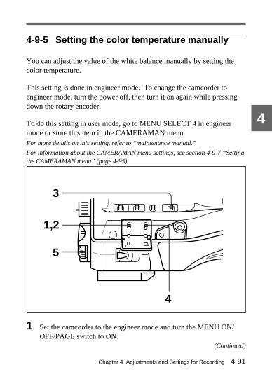
Chapter 4 Adjustments and Settings for Recording 4-91
4
4-9-5 Setting the color temperature manually
You can adjust the value of the white balance manually by setting thecolor temperature.
This setting is done in engineer mode. To change the camcorder toengineer mode, turn the power off, then turn it on again while pressingdown the rotary encoder.
To do this setting in user mode, go to MENU SELECT 4 in engineermode or store this item in the CAMERAMAN menu.For more details on this setting, refer to “maintenance manual.”
For information about the CAMERAMAN menu settings, see section 4-9-7 “Settingthe CAMERAMAN menu” (page 4-95).
1 Set the camcorder to the engineer mode and turn the MENU ON/OFF/PAGE switch to ON.
3
1,2
5
4
(Continued)

Chapter 4 Adjustments and Settings for Recording4-92
4
2 Push the MENU ON/OFF/PAGE switch repeatedly toward PAGE(or press the rotary encoder) until the PRESET WHT page (shownbelow) appears.
3 Set the WHITE BAL switch to PRST.
Note
If the WHTE BAL switch is not set to PRST when you operate thecamcorder, the adjustment value will not be reflected in the outputsignal.
4 Push the MENU CANCEL/PRST/ITEM switch repeatedly towardsITEM (or press the rotary encoder) until the cursor reaches the itemthat you want to change.
5 Turn the rotary encoder to change the setting of the selected item.COLOR TEMP: Sets the color temperature for the preset value.
Adjust the value while looking at the real image because errortends to be bigger for adjustment of high color temperature.
FINE: Adjusts the value more precisely when the adjustmentthrough COLOR TEMP is not satisfactory.
R GAIN: Only the value of R GAIN is changed.B GAIN: Only the value of B GAIN is changed.
E35*PRESET WHT E35*PRESET WHT
pCOLOR TEMP. <P>:? 6324 COLOR TEMP. <P>:? 6324
FINE <P>: 0 FINE <P>: 0
R GAIN <P>: 69 R GAIN <P>: 69
B GAIN <P>: -69 B GAIN <P>: -69

Chapter 4 Adjustments and Settings for Recording 4-93
4
4-9-6 Specifying an offset for the auto whitebalance setting
By setting an offset for the value of auto white balance, you can makethe picture warmer or colder.
This setting is done in engineer mode. To change the camcorder toengineer mode, turn the power off, then turn it on again while pressingdown the rotary encoder.
To do this setting in user mode, go to MENU SELECT 4 in engineermode.For details on this setting, refer to “maintenance manual.”
1 Set the camcorder to engineer mode and turn the MENU ON/OFF/PAGE switch to ON.
3
1,2
5
4
(Continued)

Chapter 4 Adjustments and Settings for Recording4-94
4
2 Push the MENU ON/OFF/PAGE switch repeatedly toward PAGE(or press the rotary encoder) until the OFFSET WHT page (shownbelow) appears.
3 Set the WHITE BAL switch to channel A or B.
Note
If the WHITE BAL switch is not set to A or B when you operate thecamcorder, the adjustment value will not be reflected in the outputsignal.
4 Push the MENU CANCEL/PRST/ITEM switch repeatedly towardITEM (or turn the rotary encoder) until the cursor specifies the itemyou want to change.
5 Turn the rotary encoder to change the setting of the selectedfunction, as follows.OFFSET WHITE<A>: Turns the setting of the offset for channel A
ON or OFF.WARM-COOL<A>: While looking at the image, adjust channel A
by turning the rotary encoder towards + (to produce a warmimage) or towards – (for a cool image).
FINE<A>: Adjusts the value more precisely if the adjustment byWARM-COOL<A> is not satisfactory.
E34*OFFSET WHT E34*OFFSET WHT
pOFFSET WHITE<A>:? ON OFFSET WHITE<A>:? ON
WARM-COOL <A>: 0 WARM-COOL <A>: 0
FINE <A>: 0 FINE <A>: 0
OFFSET WHITE<B>: OFF OFFSET WHITE<B>: OFF
WARM-COOL <B>: 0 WARM-COOL <B>: 0
FINE <B>: 0 FINE <B>: 0

Chapter 4 Adjustments and Settings for Recording 4-95
4
OFFSET WHITE <B>: Turns the setting of the offset for channelB ON or OFF.
WARM-COOL<B>: While looking at the image, adjust channel Bby turning the rotary encoder towards + (to produce a warmimage) or towards – (for a cool image).
FINE<B>: Adjusts the value more precisely if the adjustment byWARM-COOL<B> is not satisfactory.
4-9-7 Setting the CAMERAMAN menu
You can recall your frequently used menu items quickly by storing thesemenu items in CAMERAMAN menu (up to 5 pages).
A maximum of 10 items can be stored in each page. If you try to storemore than 10 items on 1 page, only first 10 items input will be stored.
Normal operations are disabled while you are storing items inCAMERAMAN menu. After setting the CAMERAMAN menu,be sure to turn the power off, then on again.
To change to CAMERAMAN menu storage modeTurn the power off. Then turn the power on again while pressing theASSIGNABLE button.When “C01∗MARKER 1/3” appears on the MENU screen, thecamcorder is in CAMERAMAN menu storage mode.
Note
The MARKER 1/3 page may not appear if you release theASSIGNABLE button too soon.Turn the power off and try again.

Chapter 4 Adjustments and Settings for Recording4-96
41 Push the MENU ON/OFF/PAGE switch repeatedly toward PAGE
(or turn the rotary encoder) until the page that contains the item youwant to store appears .
2 Push the MENU CANCEL/PRST/ITEM switch repeatedly towardITEM (or turn the rotary encoder) until the cursor is beside the item.
?C01*MARKER 1/3 ?C01*MARKER 1/3
SAFETY ZONE : OFF SAFETY ZONE : OFF
SAFETY AREA : OFF SAFETY AREA : OFF
CENTER : OFF CENTER : OFF
CENTER H : OFF CENTER H : OFF
CENTER V : OFF CENTER V : OFF
C01*MARKER 1/3 C01*MARKER 1/3
SAFETY ZONE : OFF SAFETY ZONE : OFF
SAFETY AREA : OFF SAFETY AREA : OFF
pCENTER : 1 CENTER : 1
CENTER H : OFF CENTER H : OFF
CENTER V : OFF CENTER V : OFF

Chapter 4 Adjustments and Settings for Recording 4-97
43 Use the rotary encoder to specify the page number (1 to 5) to be
stored to.
To cancel the storage procedure, specify OFF.
4 Turn the power off, then on again.
After storage has been completedCAMERAMAN menu (1 to 5) page appears, followed by MARKER 1/3page.
? U1*CAMERAMAN 1 ? U1*CAMERAMAN 1
CENTER : OFF CENTER : OFF
MASTER BLACK : 0 MASTER BLACK : 0
MASTER GAMMA : 0 MASTER GAMMA : 0
C21*LEVEL 4 C21*LEVEL 4
MASTER BLACK : 1 MASTER BLACK : 1
pMASTER GAMMA : 1 MASTER GAMMA : 1
MASTER BLK GAMMA: OFF MASTER BLK GAMMA: OFF
KNEE POINT : 98% KNEE POINT : 98%
KNEE SLOPE : 0 KNEE SLOPE : 0
KNEE SATURATION : 0 KNEE SATURATION : 0
KNEE : OFF KNEE : OFF
WHITE CLIP : OFF WHITE CLIP : OFF
WHITE CLIP LEVEL: OFF WHITE CLIP LEVEL: OFF

Chapter 4 Adjustments and Settings for Recording4-98
4
Notes
• The CAMERAMAN menu pages will not appear if no items have beenstored.
• If the settings in CAMERAMAN menu 1 to 5 (of MENU SELECT 5 inengineer mode) are OFF, the CAMERAMAN menu pages will notappear even if items are stored.
For more details, refer to “maintenance manual.”
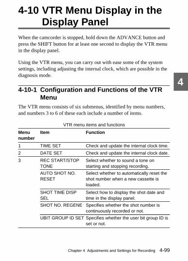
Chapter 4 Adjustments and Settings for Recording 4-99
4
4-10 VTR Menu Display in theDisplay Panel
When the camcorder is stopped, hold down the ADVANCE button andpress the SHIFT button for at least one second to display the VTR menuin the display panel.
Using the VTR menu, you can carry out with ease some of the systemsettings, including adjusting the internal clock, which are possible in thediagnosis mode.
4-10-1 Configuration and Functions of the VTRMenu
The VTR menu consists of six submenus, identified by menu numbers,and numbers 3 to 6 of these each include a number of items.
VTR menu items and functions
Menunumber
Item Function
1 TIME SET Check and update the internal clock time.
2 DATE SET Check and update the internal clock date.
3 REC START/STOPTONE
Select whether to sound a tone onstarting and stopping recording.
AUTO SHOT NO.RESET
Select whether to automatically reset theshot number when a new cassette isloaded.
SHOT TIME DISPSEL
Select how to display the shot date andtime in the display panel.
SHOT NO. REGENE Specifies whether the shot number iscontinuously recorded or not.
UBIT GROUP ID SET Specifies whether the user bit group ID isset or not.

Chapter 4 Adjustments and Settings for Recording4-100
4
4 LTC UBIT Select the contents of the LTC user bits.
LTC UBIT MARKER Select which LTC user bit markers torecord.
Menunumber
Item Function
REC STARTMARKER
Select whether to record recording startmarkers.
SHOT MARKER 1 Select whether to record shot markers 1.
SHOT MARKER 2 Select whether to record shot markers 2.
5 VITC UBIT Select information to be recorded in theVITC user bits.
SHOT DATA Select the VITC UBIT DATA mode.
6 WATCH IC REVISE Check and update the internal clockadjustment.
4-10-2 Using the VTR MenuTo access the VTR menu, hold down the ADVANCE button and pressthe SHIFT button for at least one second.For operations within the VTR menu, use the SHIFT, ADVANCE,HOLD, and RESET buttons.To exit the VTR menu, hold down the ADVANCE button and press theSHIFT button.

Chapter 4 Adjustments and Settings for Recording 4-101
4
Buttons used in the VTR menu
Operations in the VTR menu relating to the internal clockMenu numbers 1, 2 and 6 are for settings relating to the internal clock.The following summarizes the procedure in these menus.
1 Access the VTR menu.
2 For menu numbers 2 and 6, press the ADVANCE button to move tothe required menu number.
3 Press the SHIFT button.
HOLD button
RESET button
SHIFTbutton
ADVANCE button
OFF
ON
DISPLAY
LIGHTRESET
HOLD
WARNINGCTLTC
DATA
ADVANCE
PRESET
F-RUNSET
DIAG
R-RUN
DATADISPLAY
NDFDF
REGEN
CLOCK
AUDIO INAUDIO SELECT
REAR
MIXCH-1 CH-2
FRONT
SHIFT
MANUALAUTO
LEVELCH-1••
••
•
• •
••
•
•
0 10
CH-2••
••
•
• •
••
•
•
CUE IN
0 10
U-BITSHOT TIME
NO.
H MIN SEC FRM
40
PEAK dB
OVER EMPH OVER
TAPE E B
VH
HOLDDIAG PB VITC NDF EXT-LK
RF SERVO HUMID SLACK
00:00:00:00
BATT E x x x x x x x
x x x x x x x
F
1 2
30
10
0
•
20
(Continued)

Chapter 4 Adjustments and Settings for Recording4-102
4
4 Change the internal clock setting as required.
5 Press the SHIFT button.
6 Exit the VTR menu.For details of operation for menu numbers 1, 2, and 6, see the respective sections,“Changing the time setting of the internal clock” (page 4-106), “Changing the datesetting of the internal clock” (page 4-107), and “Changing the internal clockadjustment” (page 4-111).
Operations in the VTR menu not relating to the internal clockMenu numbers 3 to 5 each include a number of functions. Each settingis generally a binary choice (such as ON/OFF), but some settings havethree choices.
The following summarizes the procedure in these menus.
1 Access the VTR menu.
2 Press the ADVANCE button to move to the required menu number.
3 Press the SHIFT button repeatedly until the setting you wish tochange is flashing.
4 Press the ADVANCE button to change the setting.
5 Press the SHIFT button to advance to the last function in thissubmenu.
6 Press the SHIFT button once more.
7 Exit the VTR menu.

Chapter 4 Adjustments and Settings for Recording 4-103
4
Menu item settings and indications in the display panel
TIME SETSetting Indication
Internal clock time 1:xx xx xx
DATE SETSetting Indication
Internal clock date 2:xx xx xx
REC START/STOP TONESetting Indication
No tone on starting and stoppingrecording
3:0xx
Sound tone on starting andstopping recording
3:1xx
AUTO SHOT NO. RESETSetting Indication
Reset shot number when newcassette loaded
3:x0x
Do not reset shot number whennew cassette loaded
3:x1x
SHOT TIME DISP SELSetting Indication
Show shot time as “month-day:hour-minute” 3:xx0
Show shot time as “day-month:hour-minute” 3:xx1
Show shot time as “day:hour-minute-second” 3:xx2
(Continued)

Chapter 4 Adjustments and Settings for Recording4-104
4
SHOT NO. REGENESetting Indication
The shot number is recorded continuously. 3:xxx0
The shot number is not recorded continuously. 3:xxx1
UBIT GROUP ID SETSetting Indication
The UBIT group ID is not set. 3:xxxx0
The UBIT group ID is set. 3:xxxx1
LTC UBITSetting Indication
Set LTC user bits to fixed user bit values 4:0xxxx
Set LTC user bits to real time 4:1xxxx
Record shot data in LTC user bits 4:2xxxx
LTC UBIT MARKERSetting Indication
LTC user bit marker recording determined byREC START MARKER and GOOD SHOTMARKER items
4:x0xxx
Both markers (REC START MARKER and GOODSHOT MARKER) recorded in LTC user bits
4:x1xxx
No markers recorded in LTC user bits 4:x2xxx

Chapter 4 Adjustments and Settings for Recording 4-105
4
REC START MARKER 1)
Setting Indication
Recording start marker recorded in user bits 4:x00xx
Recording start marker not recorded in user bits 4:x01xx
1) This switch is effective when the LTC UBIT MARKER setting is 0 (“SW”).
SHOT MARKER 1 2)
Setting Indication
Shot marker 1 recorded in user bits 4:x0x0x
Shot marker 1 not recorded in user bits 4:x0x1x
2) This switch is effective when the LTC UBIT MARKER setting is 0 (“SW”).
SHOT MARKER 2 3)
Setting Indication
Shot marker 2 recorded in user bits 4:x0xx0
Shot marker 2 not recorded in user bits 4:x0xx1
3) This switch is effective when the LTC UBIT MARKER setting is 0 (“SW”).
VITC UBITSetting Indication
Set VITC user bits to fixed user bit values 5:0x
Set VITC user bits to real time 5:1x
Record shot data in VITC user bits 5:2x
SHOT DATASetting Indication
Use standard mode for shot data 5:20
Use extended mode for shot data 5:21
(Continued)

Chapter 4 Adjustments and Settings for Recording4-106
4
WATCH IC REVISESetting Indication
Adjustment for internal clock (frames/hour) 6:xxx
4-10-3 Example Operations in the VTR MenuThis section describes typical examples of setting operations carried outusing the VTR menu.
Changing the time setting of the internal clock
1 Hold down the ADVANCE button and press the SHIFT button for atleast one second.
This displays the VTR menu.
2 Press the SHIFT button.
The hours indication flashes.
3 Set the hours value.
To increase the value, press the ADVANCE button.
To decrease the value, hold down the HOLD button and press theADVANCE button.
4 Press the SHIFT button.
The minutes indication flashes.
5 Set the minutes value.

Chapter 4 Adjustments and Settings for Recording 4-107
4
To increase the value, press the ADVANCE button.
To decrease the value, hold down the HOLD button and press theADVANCE button.
6 Press the RESET button to set the seconds value to 00.
If before you press the RESET button the seconds value is less than30, the minutes value does not change. If before you press theRESET button the seconds value is 30 or more, the minutes value isincremented by 1 at the moment the seconds value changes to 00.
7 Press the SHIFT button.
The corrected time appears in the display.
8 Hold down the ADVANCE button and press the SHIFT button toexit the VTR menu.
Changing the date setting of the internal clock
1 Hold down the ADVANCE button and press the SHIFT button for atleast one second.
This displays the VTR menu.
2 Press the ADVANCE button once.
This moves to DATE SET.
3 Press the SHIFT button.
The year indication flashes.
4 Set the year.
(Continued)

Chapter 4 Adjustments and Settings for Recording4-108
4
To increase the value, press the ADVANCE button.
To decrease the value, hold down the HOLD button and press theADVANCE button.
5 Press the SHIFT button.
The month indication flashes.
6 Set the month.
To increase the value, press the ADVANCE button.
To decrease the value, hold down the HOLD button and press theADVANCE button.
7 Press the SHIFT button.
The day indication flashes.
8 Set the day.
To increase the value, press the ADVANCE button.
To decrease the value, hold down the HOLD button and press theADVANCE button.
9 Press the SHIFT button.
The corrected date appears in the display.
10 Hold down the ADVANCE button and press the SHIFT button toexit the VTR menu.

Chapter 4 Adjustments and Settings for Recording 4-109
4
Sounding a tone on starting and stopping recording
1 Hold down the ADVANCE button and press the SHIFT button for atleast one second.
This displays the VTR menu.
2 Press the ADVANCE button twice.
3 Press the SHIFT button.
The current setting of REC START/STOP TONE flashes.
4 Press the ADVANCE button until the displayed setting value is 1.
In the viewfinder, this appears as “ON”.
5 Press the SHIFT button three times.
This saves the new setting value.
6 Hold down the ADVANCE button and press the SHIFT button toexit the VTR menu.
If the new setting is not saved correctlyWhen you press the SHIFT button in step 5, an indication “3:Ex xx”appears. Make the setting once more.
Recording all markers in the LTC user bits
1 Hold down the ADVANCE button and press the SHIFT button for atleast one second.
This displays the VTR menu.
2 Press the ADVANCE button three times.(Continued)

Chapter 4 Adjustments and Settings for Recording4-110
4
3 Press the SHIFT button twice.
The current setting of LTC UBIT MARKER flashes.
4 Press the ADVANCE button until the displayed setting value is 1.
5 Press the SHIFT button three times.
This saves the new setting value.
6 Hold down the ADVANCE button and press the SHIFT button toexit the VTR menu.
If the new setting is not saved correctlyWhen you press the SHIFT button in step 5, an indication “4:Ex xx x”appears. Make the setting once more.(Continued)
Recording shot data in the VITC user bits
1 Hold down the ADVANCE button and press the SHIFT button for atleast one second.
This displays the VTR menu.
2 Press the ADVANCE button four times.
3 Press the SHIFT button.
The current setting of VITC UBIT flashes.
4 Press the ADVANCE button until the displayed setting value is 2.
5 Press the SHIFT button twice.
This saves the new setting value.

Chapter 4 Adjustments and Settings for Recording 4-111
4
6 Hold down the ADVANCE button and press the SHIFT button toexit the VTR menu.
If the new setting is not saved correctlyWhen you press the SHIFT button in step 5, an indication “5:Exx”appears. Make the setting once more.
Changing the internal clock adjustmentThe rate of advancement of the internal clock while the camcorder ispowered off can be adjusted as follows.
1 Hold down the ADVANCE button and press the SHIFT button for atleast one second.
This displays the VTR menu.
2 Press the ADVANCE button six times.
3 Press the SHIFT button.
The current setting of the internal clock adjustment value flashes.
4 Set the adjustment value (number of frames/day).
To increase the value, press the ADVANCE button.
To decrease the value, hold down the HOLD button and press theADVANCE button.
5 Press the SHIFT button.
This saves the new setting value.
6 Hold down the ADVANCE button and press the SHIFT button toexit the VTR menu.
(Continued)
Chapter 4 Adjustments and Settings for Recording4-112
4
If the new setting is not saved correctlyWhen you press the SHIFT button in step 5, an indication “6:E x xx”appears. Make the setting once more.

Chapter 4 Adjustments and Settings for Recording 4-113
4
4-11 Using the Setup CardYou can save the contents of the setup menu in the BSC-1 Setup Card(not supplied). This data enables rapid recreation of suitable setupconditions.
4-11-1 Handling the Setup CardThe setup card can be inserted or removed from the camcorder with thepower turned on or off.
Removing the setup cardPush up on the tab on the right-hand side of the card insertion lid to openthe lid.
Removing the setup card
Note
Do not touch the pins on the card connector.

Chapter 4 Adjustments and Settings for Recording4-114
4
Inserting the setup cardWith SONY logo on the setup card facing you (you should be able toread the text), insert the card completely into the insertion slot, then closethe lid.
Inserting the setup card
Note
Make sure that you can read the “SONY” logo when you insert the card.If there is some resistance when you insert the card, the card might beturned around or upside down. Do not force the card into the slot. Checkthat the card is correctly oriented, then try inserting it again.
Using and storing the setup cardThe following points apply to the use and storage of a setup card.• Avoid high temperature and humidity.• Make sure the card does not get dirty or wet.• Avoid static electricity.• Store the card by inserting it into the camcorder and closing the card
insertion lid.

Chapter 4 Adjustments and Settings for Recording 4-115
4
4-11-2 Using Data on the Setup CardThe operations of saving data to the setup card and reading the saveddata from the setup card are done from the SETUP CARD page of thesetup menu.
Writing data to the setup cardFollow the procedure below.
Writing data to the setup card
1 Set the MENU ON/OFF/PAGE switch to ON.
The page that was on the screen when the last menu operation endedappears on the viewfinder screen. (When this menu is first used, thelowest-numbered one of the currently selected pages appears.)
1,2,7
4,6
3,5
(Continued)
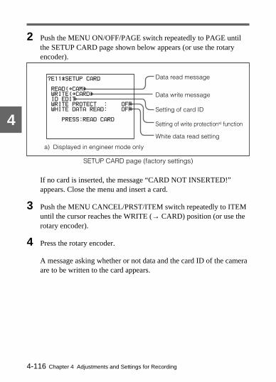
Chapter 4 Adjustments and Settings for Recording4-116
4
Data read message
Data write message
Setting of card ID
Setting of write protectiona) function
White data read setting
2 Push the MENU ON/OFF/PAGE switch repeatedly to PAGE untilthe SETUP CARD page shown below appears (or use the rotaryencoder).
SETUP CARD page (factory settings)
If no card is inserted, the message “CARD NOT INSERTED!”appears. Close the menu and insert a card.
3 Push the MENU CANCEL/PRST/ITEM switch repeatedly to ITEMuntil the cursor reaches the WRITE (→ CARD) position (or use therotary encoder).
4 Press the rotary encoder.
A message asking whether or not data and the card ID of the cameraare to be written to the card appears.
a) Displayed in engineer mode only
?E11*SETUP CARD ?E11*SETUP CARD
READ( READ(pCAM) CAM)
WRITE( WRITE(pCARD) CARD)
ID EDIT ID EDIT
WRITE PROTECT : OFF WRITE PROTECT : OFF
WHITE DATA READ: OFF WHITE DATA READ: OFF
PRESS:READ CARD PRESS:READ CARD

Chapter 4 Adjustments and Settings for Recording 4-117
45 • To end writing data, push the MENU CANCEL/PRST/ITEM
switch to CANCEL/PRST.• To continue the writing of data, go on to step 6.
6 Press the rotary encoder.
The displayed card ID and the setting data stored in the camcorderare written to the card.While the data is being written, the message “WRITING DATA!” isdisplayed.
When the writing is completed, the message “WRITE : OK”appears.
7 To end the menu operation, set the MENU ON/OFF/PAGE switch toOFF.
The setup menu disappears from the viewfinder screen and thedisplays indicating the current status of the camcorder appear alongthe top and bottom of the viewfinder.
E11*SETUP CARD E11*SETUP CARD
READ( READ(pCAM) CAM)
pWRITE(WRITE(pCARD) CARD)
ID EDIT ID EDIT
WRITE PROTECT : OFF WRITE PROTECT : OFF
WHITE DATA READ: OFF WHITE DATA READ: OFF
ID: ID:
WRITE? (Y:PRESS) WRITE? (Y:PRESS)
(Continued)

Chapter 4 Adjustments and Settings for Recording4-118
4
Updating the dataIf data is already saved on the card, a message asking whether or not thatdata is to be updated is displayed in step 6 (page 4-117). The message isillustrated below.
To update the data, press the rotary encoder.
E11*SETUP CARD E11*SETUP CARD
READ( READ(pCAM) CAM)
pWRITE(WRITE(pCARD) CARD)
ID EDIT ID EDIT
WRITE PROTECT : OFF WRITE PROTECT : OFF
WHITE DATA READ: OFF WHITE DATA READ: OFF
ID: ID:
CARD CONTAINS DATA! CARD CONTAINS DATA!
REPLASE? (Y:PRESS) REPLASE? (Y:PRESS)

Chapter 4 Adjustments and Settings for Recording 4-119
4
Protecting saved dataIf you set the WRITE PROTECT setting to “ON” in engineer mode toprotect data written to a setup card, then pressing the rotary encoder instep 6 of the foregoing procedure (page 4-117) does not carry outoverwriting. Follow the procedure below (possible in engineer modeonly).
Protecting saved data
1 Move the cursor to the WRITE PROTECT position.
1
2
E11*SETUP CARD READ(pCAM) WRITE(pCARD) ID EDIT pWRITE PROTECT : OFF WHITE DATA READ: OFF

Chapter 4 Adjustments and Settings for Recording4-120
4
2 • To enable the write-protection function (the “ON” setting), turnthe rotary encoder counterclockwise as seen from the front of thecamera.
• To disable the write-protection function (the “OFF” setting), turnthe rotary encoder clockwise.
If data cannot be writtenIf when you press the rotary encoder in step 6 of the foregoing procedure(page 4-116) one of the following error messages appears, then the datawas not written.
Data write error messages
Error message Reason Action
CARD NOTINSERTED!
No setup card isinserted.
Close the menu and insert orreinsert the card.
WRITEPROTECTED!
WRITE PROTECTis set to ON.
Set WRITE PROTECT to OFF.
WRITE ERROR!(flashing)
Circuit or card fault Check the circuitry, or replace thecard with a verified card.
Reading saved data from a cardFollow the procedure below.
Reading saved data from a card
1,2,7
4,6
3,5

Chapter 4 Adjustments and Settings for Recording 4-121
4
Data write message
Setting of card ID
Data read message
1 Set the MENU ON/OFF/PAGE switch to ON.
The page that was on the screen when the last menu operation endedappears on the viewfinder screen. (When this menu is first used, thelowest-numbered one of the currently selected pages appears.)
2 Push the MENU ON/OFF/PAGE switch repeatedly to PAGE untilthe SETUP CARD page shown below appears (or use the rotaryencoder).
SETUP CARD page (factory settings)
If no card is inserted, the message “CARD NOT INSERTED!”message appears. Close the menu and insert a card.
3 Push the MENU CANCEL/PRST/ITEM switch repeatedly to ITEMuntil the cursor reaches the READ (→ CAM) position (or use therotary encoder).
4 Press the rotary encoder.
A message asking whether or not data and the card ID of the cameraare to be read from the card appears.
E11*SETUP CARD
pREAD(pCAM) WRITE(pCARD) ID EDIT
WRITE PROTECT : OFF
WHITE DATA READ: OFF
PRESS:READ CARD
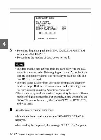
Chapter 4 Adjustments and Settings for Recording4-122
45 • To end reading data, push the MENU CANCEL/PRST/ITEM
switch to CANCEL/PRST.• To continue the reading of data, go on to step 6.
Notes
• The data and the card ID read from the card overwrite the datastored in the camcorder. Before going on to step 6, re-check thecard ID and decide whether it is necessary to read the data andcard ID from the card.
• The card stores data for both user-mode settings and engineer-mode settings. Both sets of data are read and written together.For more information, refer to “maintenance manual.”
• There is no setup card read-write compatibility between differentmodels of digital camcorder. For example, a card written by theDVW-707 cannot be read by the DVW-790WS or DVW-707P,and vice versa.
6 Press the rotary encoder once more.
While data is being read, the message “READING DATA!” isdisplayed.
When reading is completed, the message “READ : OK” appears.
E11*SETUP CARD E11*SETUP CARD
pREAD(READ(pCAM) CAM)
WRITE( WRITE(pCARD) CARD)
ID EDIT ID EDIT
WRITEWRITE PROTECTPROTECT : OFF OFF
WHITE DATA READ: OFF WHITE DATA READ: OFF
ID: ID:
READ? (Y:PRESS) READ? (Y:PRESS)

Chapter 4 Adjustments and Settings for Recording 4-123
4
7 To end the menu operation, set the MENU ON/OFF/PAGE switch toOFF.
The setup menu disappears from the viewfinder screen and thedisplays indicating the current status of the camcorder appear alongthe top and bottom of the viewfinder.
If data cannot be readIf when you press the rotary encoder in step 6 of the above procedure(page 4-122) one of the following error messages appears, then the datawas not read.
Reading white data for AWBThe white data for AWB can be read from a card only when WHITEDATA READ is set to ON.
Data read error messages
Error message Reason Action
CARD NOTINSERTED!
No setup card is inserted. Close the menu and insertor reinsert the card.
READ ERROR!(flashing)
Circuit or card fault Re-check, and consult aSony representative.
CARD DATA NG!(flashing)
The card contains the datathat cannot be read intothis camcorder.
Do not try to read the datawritten for anothercamcorder.
(Continued)

Chapter 4 Adjustments and Settings for Recording4-124
4
Setting the card IDWhen data is written to a setup card, it is useful to set an ID for the cardto identify it.When data is saved to a card, a card ID is written to the card togetherwith the data. When data is read from a card, the card ID is also read, andthat ID overwrites the card ID associated with the data that waspreviously in the camcorder.
1 Move the cursor to ID EDIT on the SETUP CARD page.
2 Press the rotary encoder.
The currently set card ID appears. If no card ID is currently set, 10spaces (s) appear. The cursor is at the left-most character or space.
3 Turn the rotary encoder clockwise as seen from the front of thecamera until the character you wish to set appears.
The character display cycles from the alphabet, through the symbols,and the digits in that order. Turn the rotary encodercounterclockwise to cycle through the characters in the reversedirection.
Currently set card ID,or 10 spaces
E11*SETUP CARD
READ(pCAM) WRITE(pCARD) pID EDIT WRITE PROTECT : OFF
WHITE DATA : OFF
o ID:
READ? (Y:PRESS)

Chapter 4 Adjustments and Settings for Recording 4-125
4
4 Press the rotary encoder to advance the cursor to the next position.
When the settings are completed, press the rotary encoder repeatedlyuntil the cursor reaches the rightmost position.
To set another character, return to step 3.When 10 characters are set, EDIT mode is exited automatically.
5 To change the card ID, press the MENU CANCEL/PRST/ITEMswitch toward the CANCEL position.
If a correction is required after once pressing the rotary encoder,press the rotary encoder once again, to display the cursor above thecard ID and enable correction (returning to the state in step 2).
Notes
• Shot ID-1 is read and written always together with other data.Therefore, if shot ID-1 is written to a card after being set or modifiedthrough the SETUP CARD page for data stored in the camera, otherdata than shot ID-1 will also be written onto the card. Shot ID-2 toshot ID-4 are not recorded on the setup card.
• To set or modify only the card ID of data stored on a card, read the datafrom the card to the camcorder, set or modify the card ID, then writethat data back to the card.

Chapter 4 Adjustments and Settings for Recording4-126
4
Chapter 5 Setting Up the Camcorder 5-1
5
Setting U
p the Cam
corder5-1 Power SupplyYou need to power on the camcorder for the flange focal lengthadjustment, viewfinder focus and screen adjustment, etc., which aredescribed later.The following power supplies can be used with the camcorder.• A BP-L60A/L90A lithium-ion battery pack• An NP-1B or a BP-90A Ni-Cd battery pack• AC power using AC-550/550CE or AC-DN1/DN2AAlternatively, you can make combined use of internal and externalbatteries, by mounting one of the above batteries as an internal batteryand connecting an external battery that can be a BP-90A contained in aDC-210 Battery Adaptor and connected to the DC IN connector of thecamcorder.
5-1-1 Using a BP-L60A/L90A Battery PackWith a battery pack, the camcorder will operate continuously for the timelisted in the table below.
Approximate continuous operating time with BP-L60A/L90A Battery Pack
DVW-707/707P DVW-709WS/ DVW-790WS/709WSP 790WSP
BP-L60A 135 minutes 125 minutes 120 minutes
BP-L90A 205 minutes 190 minutes 185 minutes
Before use, charge the battery pack with a BC-L100/L100CE BatteryCharger. It takes about 2.5 hours to charge one BP-L60A, and about 3.5hours to charge one BP-L90A.For more information, refer to the BC-L100/L100CE manual.
Note on using the battery pack
A warm battery pack may not be able to be fully recharged.
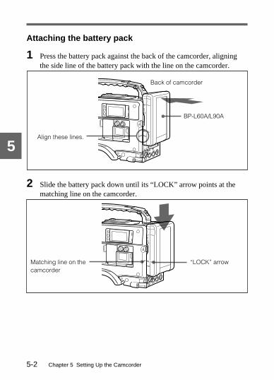
Chapter 5 Setting Up the Camcorder5-2
5
Attaching the battery pack
1 Press the battery pack against the back of the camcorder, aligningthe side line of the battery pack with the line on the camcorder.
2 Slide the battery pack down until its “LOCK” arrow points at thematching line on the camcorder.
BP-L60A/L90A
Align these lines.
Back of camcorder
Matching line on thecamcorder
“LOCK” arrow
LOCK
LOCK

Chapter 5 Setting Up the Camcorder 5-3
5
Detaching the battery pack
Detaching the battery pack
Holding the button in,pull the battery pack up.LOCK

Chapter 5 Setting Up the Camcorder5-4
5
5-1-2 Using an NP-1B Battery PackThe camcorder will operate continuously for about 40 minutes with anNP-1B Battery Pack. Use of this battery pack requires a DC-L1 BatteryAdaptor (not supplied).Before use, charge the battery pack with a BC-1WD/1WDCE BatteryCharger for about 1 hour.For more information, refer to the BC-1WD/1WDCE manual.
Attaching the battery pack
1 Slide an NP-1B Battery Pack into the DC-L1 Battery Adaptor.
NP-1B
DC-L1

Chapter 5 Setting Up the Camcorder 5-5
5
2 Mount the DC-L1 Battery Adaptor on the back of the camcorder.
5-1-3 Using a BP-90A Battery PackThe camcorder will operate for about 120 minutes (DVW-707/707P),110 minutes (DVW-709WS/709WSP) or 105 minutes (DVW-790WS/790WSP) with a BP-90A Battery Pack. Use of this battery pack requiresa DC-L90 Battery Adaptor (not supplied).Before use, charge the battery pack with a BC-210/210CE/410/410CEBattery Charger for about 2 hours.For more information, refer to the BC-210/210CE/410/410CE or BC-L100/L100CE manual.
Back of camcorder

Chapter 5 Setting Up the Camcorder5-6
5
Attaching the battery pack
1 Fit a BP-90A Battery Pack in the DC-L90 Battery Adaptor.
2 Mount the DC-L90 Battery Adaptor on the back of the camcorder.
3 Insert the battery pack.4 Connect the plug.5 Close the side cover
and push the leverdown.
Back of camcorder
1 Push the lever up.2 Open the side cover.
1
2
g3
4
5

Chapter 5 Setting Up the Camcorder 5-7
5
5-1-4 Avoiding Breaks in Operation Due to DeadBatteries
If you use both an internal battery pack and an external battery connectedto the DC IN connector at the same time, you can avoid breaks inoperation due to the dead batteries.
When the external battery begins to fail and an internalbattery pack is also usedRemove the DC output cable of the external battery from the DC INconnector. The power source will switch to the internal battery pack.
When the external battery begins to fail and an internalbattery pack is not usedFirst load the camcorder with a fully charged internal battery pack, thenremove the DC output cable of the external battery from the DC INconnector. The power source will switch to the internal battery pack. Touse an external battery again, connect a fully charged external battery tothe DC IN connector before unloading the internal battery pack. Thepower source will switch to the external battery.
Continuous operation when operating with only an internalbattery packFirst, connect a fully charged external battery to the DC IN connector,then change the internal battery.
Notes
• Whenever an internal battery pack is loaded and an external battery isconnected to the DC IN connector, the external battery is always usedas the power source.
• There may be some noise on the video signal at the instant the powersources are switched.

Chapter 5 Setting Up the Camcorder5-8
5
5-1-5 Using an AC AdaptorUsing an AC-550/550CE AC AdaptorConnect the camcorder to the AC power supply as shown in thefollowing figure, and turn the POWER switch of the AC-550/550CE on.
Using an AC Adaptor
Using an AC-DN1/DN2A AC AdaptorMount the AC-DN1/DN2A on the camcorder in the same way as abattery, then connect to the AC power supply.The AC-DN1 can supply up to 38 W of power, and the AC-DN2A up to150 W.
Connection to an AC power supply using an AC-DN1/DN2A AC Adaptor
Wall outlet
Power switch on
DC OUT
DC output cable (supplied with the AC-550/550CE)
AC-550/550CEAC Adaptor
DC IN
To receptacle

Chapter 5 Setting Up the Camcorder 5-9
5
5-1-6 Using the Anton Bauer Ultralight SystemBy fitting the camcorder with the Anton Bauer Ultralight System, andsetting the LIGHT switch to AUTO, you can switch the light on and offautomatically as you start and stop VTR operation. (This system operateswith lights powered by 12 V, with a maximum power consumption of50 W.)
Notes
• The AC-DN1 cannot be used when the light is used.• The light cannot be used if both the CA-705/755 and camera control
unit are connected to the camcorder.
5-1-7 Using the Anton Bauer Intelligent BatterySystem
You can equip the camcorder with a special battery mount which theAnton Bauer Corporation has developed for its Intelligent BatterySystem and Ultralight System.When the camcorder is used with an Anton Bauer Digital Magnum seriesbattery, the remaining battery capacity is shown numerically in theviewfinder display.Contact your Sony representative for more information.

Chapter 5 Setting Up the Camcorder5-10
5
5-2 Adjusting the ViewfinderFor maximum viewing convenience, you can adjust the viewfinderposition in the left-right and backward-forward directions.
5-2-1 Adjusting the Viewfinder PositionAdjusting the position to left or right
Adjusting the position to left or right
1 Loosen the viewfinder left-right positioning ring.
2 Slide the viewfinder to the most convenient position.
3 Tighten the viewfinder left-right positioning ring.
Storing the camcorder in the carrying caseAlways store the camcorder with the viewfinder moved fully in thedirection opposite to the barrel and the viewfinder left-right positioningring tightened.
2
3 1

Chapter 5 Setting Up the Camcorder 5-11
5
Adjusting the position backward or forward
Adjusting the position backward or forward
1 Loosen the viewfinder front-rear positioning lever.
2 Slide the viewfinder longitudinally to the most convenient position.
3 Tighten the viewfinder front-rear positioning lever.
23
1
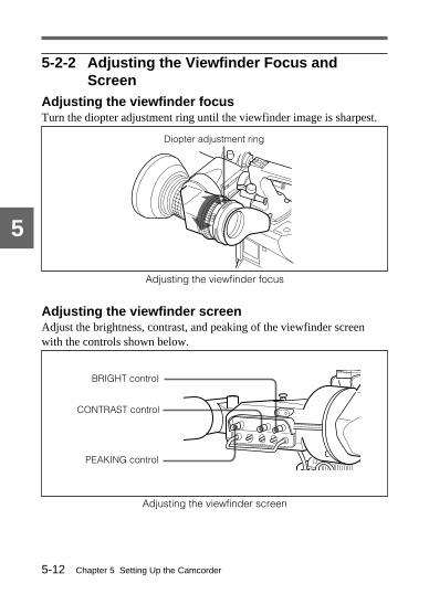
Chapter 5 Setting Up the Camcorder5-12
5
Diopter adjustment ring
BRIGHT control
CONTRAST control
PEAKING control
5-2-2 Adjusting the Viewfinder Focus andScreen
Adjusting the viewfinder focusTurn the diopter adjustment ring until the viewfinder image is sharpest.
Adjusting the viewfinder focus
Adjusting the viewfinder screenAdjust the brightness, contrast, and peaking of the viewfinder screenwith the controls shown below.
Adjusting the viewfinder screen

Chapter 5 Setting Up the Camcorder 5-13
5
Viewfinder stopper
5-2-3 Detaching the Viewfinder
Detaching the viewfinder
1 Point the viewfinder barrel up or down.
2 Loosen the viewfinder left-right positioning ring.
3 Holding the viewfinder stopper up, slide the viewfinder in thedirection indicated by the arrow and detach it.
4 Remove the viewfinder cable and microphone cable from the clampsand disconnect them.
1
3
2
4

Chapter 5 Setting Up the Camcorder5-14
5
The viewfinder rotation bracketBy fitting a BKW-401 Viewfinder Rotation Bracket (not supplied), youcan rotate the viewfinder out of the way so that your right leg does nothit the viewfinder while you are carrying the camcorder.For more information, refer to the BKW-401 manual.
Using the BKW-401 Viewfinder Rotation Bracket
,

Chapter 5 Setting Up the Camcorder 5-15
5
Locking ring
Mark (red)Mark (red)
Mark on end of eyepiece (red)
5-2-4 Detaching the EyepieceRemoving the eyepiece gives a clearer view of the screen from furtheraway. It is also easy to remove dust from the viewfinder screen andmirror when the eyepiece is detached.
1 Turn the eyepiece locking ring fully counterclockwise, to line up thered marks on the locking ring and the viewfinder barrel.
2 Detach the eyepiece.

Chapter 5 Setting Up the Camcorder5-16
5
Reattaching the eyepiece
1 Align the mark on the eyepiece locking ring with the one on theviewfinder barrel.
2 Align the mark on the eyepiece end (see step 2 in the illustration foreyepiece detachment) with those on the eyepiece locking ring andviewfinder barrel. Then insert the eyepiece into the viewfinderbarrel.
3 Turn the eyepiece locking ring clockwise until its “LOCK” arrowpoints at the mark on the viewfinder barrel.
Note
When the eyecup is worn out, replace it with a new one (service partnumber 3-723-079-02).
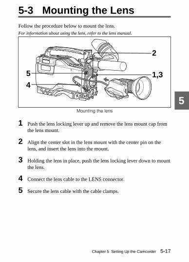
Chapter 5 Setting Up the Camcorder 5-17
5
5-3 Mounting the LensFollow the procedure below to mount the lens.For information about using the lens, refer to the lens manual.
Mounting the lens
1 Push the lens locking lever up and remove the lens mount cap fromthe lens mount.
2 Align the center slot in the lens mount with the center pin on thelens, and insert the lens into the mount.
3 Holding the lens in place, push the lens locking lever down to mountthe lens.
4 Connect the lens cable to the LENS connector.
5 Secure the lens cable with the cable clamps.
1,3
2
45

Chapter 5 Setting Up the Camcorder5-18
5
About 3 m (10 ft)
5-4 Adjusting the FlangeFocal Length
If the lens does not stay in focus properly as you zoom from telephoto towide angle, adjust the flange focal length (the distance from the plane ofthe lens mounting flange to the imaging plane). Make this adjustmentafter mounting or changing the lens.
Adjusting the flange focal lengthThe positions of the controls for adjusting the flange focal length varysomewhat from lens to lens. Check the identification of the variouscontrols in the lens manual.
Adjusting the flange focal length
1 Set the iris to manual.
2 Open the iris. Place the flange focal length adjustment chart about 3m (10 ft) away from the camera, lit well enough to provide asatisfactory video output level.

Chapter 5 Setting Up the Camcorder 5-19
5
3 Loosen the fixing screws on the Ff ring (flange focal lengthadjustment ring).
4 Use manual or power zoom to set the lens to telephoto.
5 Point the camera at the chart, and focus on it.
6 Set the zoom to wide angle.
7 Turn the Ff ring until the chart is in focus, being careful not todisturb the focus ring.
8 Repeat steps 4 to 7 until the chart stays in focus all the way fromwide angle to telephoto.
9 Tighten the Ff ring fixing screws.

Chapter 5 Setting Up the Camcorder5-20
5Connect to the MIC INconnector. Set the AUDIO IN switch for the
desired recording channel to FRONT.
5-5 Audio Input System
5-5-1 Using the Supplied MicrophoneYou can use the supplied microphone either detached from or attached tothe camcorder.
Using the microphone detached from the camcorder
Using the microphone detached from the camcorder
Note
When using the supplied microphone with an extension cable, alwaysuse an external power supply type cable.

Chapter 5 Setting Up the Camcorder 5-21
5
Microphone holder
Place the microphone in theholder so that “UP” is at the top.
Close the microphone holder.
Tighten thescrew.
(Continued)
Using the microphone attached to the camcorder
1 Loosen the screw and open the microphone holder.
2 Place the microphone in the microphone holder.
1
2
3
1
2

Chapter 5 Setting Up the Camcorder5-22
5Connect to the MIC IN connector.
3 Plug the microphone cable into the MIC IN connector, and set theAUDIO IN switch for the desired recording channel to FRONT.

Chapter 5 Setting Up the Camcorder 5-23
5Set the LINE/MIC/+48 V ONselector to +48 V ON if you usean external power supply typemicrophone. Otherwise, set theselector to MIC.
AUDIO INCH-1 or CH-2
Microphone
Set the AUDIO IN switch for the channel towhich the microphone is connected to REAR.
5-5-2 Using an External MicrophoneYou can connect up to two external microphones, using the AUDIO INCH-1 and CH-2 connectors. When you use an external power supplytype microphone, set the LINE/MIC/+48 V ON selector for theappropriate AUDIO IN connector to +48 V ON.If a microphone you use is not the external power supply type, set theLINE/MIC/+48 V ON selector to MIC.
Using a detached external microphone
Using a detached external microphone
LOCK

Chapter 5 Setting Up the Camcorder5-24
5
CRS-3P Cradle Suspension
Microphone holder (A)(Part No. 3-680-581-01)
Using an external microphone attached to thecamcorderYou can attach an external microphone to the camcorder by using aCAC-12 Microphone Holder (not supplied). Additionally, by using aCRS-3P Cradle Suspension (not supplied), you can reduce themechanical vibration noise from the VTR, and can also attach a longmicrophone. Note, however, that use of the CRS-3P requires amicrophone holder (A) (Part No. 3-680-581-01), which is not suppliedwith the CRS-3P.The procedure for attaching an external microphone using a CAC-12 andCRS-3P is shown below.Refer to the microphone holder or cradle suspension manual for more information.
1 Assemble the CRS-3P Cradle Suspension and microphone holder(A) (Part No. 3-680-581-01).

Chapter 5 Setting Up the Camcorder 5-25
5
(Continued)
2 Attach the CAC-12 Microphone Holder.
3 Open the CAC-12 and remove the microphone adaptor.
The supplied screws forthe CAC-12
CAC-12
Open the CAC-12.
Loosen the screw.
Microphone adaptor
1
2
3

Chapter 5 Setting Up the Camcorder5-26
5
Microphone
Close the CAC-12.
Tighten the screw.
4 Mount the assembly from step 1 in the CAC-12.
5 Mount the microphone into the cradle suspension.
1
2
3

Chapter 5 Setting Up the Camcorder 5-27
5
6 Connect the microphone cable to the AUDIO IN connector forchannel 1 or 2. Set the corresponding AUDIO IN switch to REAR.
Set the LINE/MIC/+48 V ON selector to +48 V ON or MIC inaccordance with the type of the microphone power supply.
Notes
• You can only connect an external power supply type microphone to theMIC IN connector.
• If the microphone you connect to the AUDIO IN CH-1/CH-2connector is of the external power supply type, set the appropriateLINE/MIC/+48 V ON selector to +48 V ON.Otherwise, set the selector to MIC.
Chapter 5 Setting Up the Camcorder5-28
5
5-5-3 Attaching a UHF Portable Tuner (for a UHFWireless Microphone System)
To use a Sony UHF wireless microphone system, fit one of the followingUHF portable tuners:• WRR-28M/810A/860A UHF Portable TunerFor each of these UHF portable tuners, use the following attachmentprocedure. (For the WRR-28M/810A/860A UHF Portable Tuner, theWRR-28M is taken as an example.)Refer to the UHF portable tuner manual for more information.
Fitting a WRR-28M (using a BP-L60A/L90A BatteryPack)
1 (1) Attach the WRR tuner fitting (not supplied, service part numberA-8278-057-A) to the back of the camcorder.1 Pass a screwdriver through the holes and tighten the screws.2 Loosen the adjustment screws.3 Adjust the metal fitting position for a BP-L60A/L90A
Battery Pack to be attached, and tighten the adjustmentscrews to fix its position.
4 Attach the BETACAM holder kit supplied with the tuner tothe WRR tuner fitting.
(2) Attach the battery pack.For more information about attaching the BP-L60A/L90A Battery Pack, seeSection 5-1-1 “Using a BP-L60A/L90A Battery Pack” (page 5-1).

Chapter 5 Setting Up the Camcorder 5-29
5
(Continued)
2 Mount the tuner on the WRR tuner fitting.
Adjustment screws
Back of camcorder
WRR-28M
Holes
BETACAM holder kit
WRR tuner fitting
LOCK
LOCK
BP-L60A/L90A

Chapter 5 Setting Up the Camcorder5-30
5DC OUT
Set the AUDIO IN switch for theappropriate channel to REAR. AUDIO IN for CH-1 or CH-2
Set the LINE/MIC/+48 V ONselector for the appropriatechannel to MIC.
3 Connect the tuner power cord to the DC OUT connector of thecamcorder, and the audio output cable to the AUDIO IN connectorfor channel 1 or 2.
Fitting a WRR-28M (using an NP-1B or BP-90A BatteryPack)Before attempting the following attachment, make sure that an NP-1BBattery Pack is contained in the DC-L1 Battery Adaptor or that aBP-90A Battery Pack is contained in the DC-L90 Battery Adaptor.
LOCK

Chapter 5 Setting Up the Camcorder 5-31
5
1 Attach the BETACAM holder kit supplied with the tuner to theWRR tuner fitting.
2 Mount the tuner on the battery adaptor.
BETACAM holder kit
WRR-28M
1 Attach the hook to the bracket.2 Tighten the screw.
1
2
(Continued)

Chapter 5 Setting Up the Camcorder5-32
5
Set the LINE/MIC/+48 V ON selectorfor the appropriatechannel to MIC.
AUDIO IN CH-1 or CH-2
DC OUTSet the AUDIO IN switch for theappropriate channel to REAR.
3 Connect the tuner power cord to the DC OUT connector of thecamcorder, and the audio output cable to the AUDIO IN CH-1 orCH-2 connector.

Chapter 5 Setting Up the Camcorder 5-33
5
5-5-4 Connecting Line Input Audio EquipmentConnect the audio output connector of the audio equipment that suppliesthe line input signal to the AUDIO IN CH-1 or CH-2 connector.
Line input connection
AUDIO IN CH-1 or CH-2
Set the LINE/MIC/+48 VON selector for theappropriate channel toLINE.
Audio equipment
Set the AUDIO IN switch for theappropriate channel to REAR.
LOCK

Chapter 5 Setting Up the Camcorder5-34
5
5-6 Tripod MountingYou can easily mount and dismount the camcorder on a tripod by usingthe tripod adaptor (not supplied).
1 Attach the tripod adaptor to the tripod.
2 Mount the camcorder on the tripod adaptor.
Tripod adaptor
Select the screw hole in thetripod adaptor that fits thescrew on your tripod cameramount and gives the bestbalance for the camcorder.
Slide the camcorder forward alongthe groove in the adaptor until itclicks.
Camera mount

Chapter 5 Setting Up the Camcorder 5-35
5
Removing the camcorder from the tripod adaptor
Removing the camcorder from the tripod adaptor
Note
The tripod adaptor pin may remain in the engaged position even after thecamcorder is removed. If this happens, press the red button against thelever a second time and move the lever as shown below until the pinreturns to the stowed position. If the pin remains in the engaged position,you will not be able to mount the camcorder on the tripod adaptor.
If the pin remains in the engaged position
LeverRed button
Press the redbutton againstthe lever andmove the leverindicated by thearrow.
Stowed position
Pin
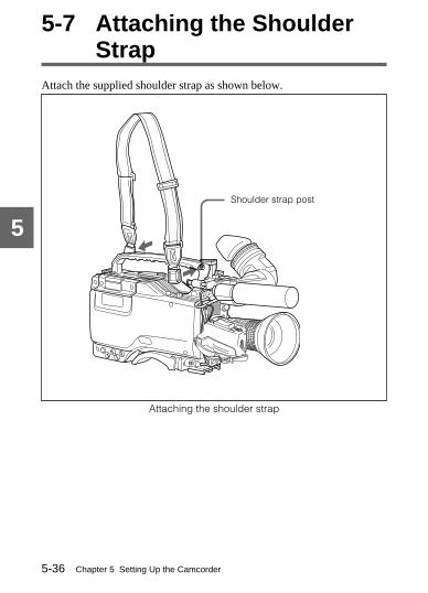
Chapter 5 Setting Up the Camcorder5-36
5Shoulder strap post
5-7 Attaching the ShoulderStrap
Attach the supplied shoulder strap as shown below.
Attaching the shoulder strap

Chapter 5 Setting Up the Camcorder 5-37
5
Pull up the strap tolock the fitting.
Removing
Attaching
Clip
Press here to release.
Attaching the shoulder strap
Removing the shoulder strap
g
g

Chapter 5 Setting Up the Camcorder5-38
5
Bottom view
Shoulder pad
5-8 Adjusting the ShoulderPad Position
You can shift the shoulder pad from its center position backward orforward by up to 10 mm (3/8 inch). This adjustment helps you get thebest balance for shooting with the camcorder on your shoulder.
Adjusting the shoulder pad position
1 Loosen the two screws.
2 Slide the shoulder pad backward or forward until it is in the mostconvenient position.
3 Tighten the screws.
1,3
2

Chapter 5 Setting Up the Camcorder 5-39
5
5-9 Putting On the RainCover
Attach the optional rain cover as illustrated below. This cover is sodesigned that you can change cassettes, reach the controls, and mount thecamcorder on a tripod with the cover on.
When attaching theshoulder strap, pass itthrough these sleevesand fasten thedrawstrings.
Insert your hand here to holdthe grip.
When attaching a video light,pass it through this velcrotape opening.
Back
Button A
Button B
Button C
Change cassettesthrough this sleeve.
If you have fitted the BKW-401Viewfinder Rotation Bracket (notsupplied), unhook button C frombutton A and insert the end of themicrophone here.
Front
Close the velcro tape.
Access the controls onthe camcorder throughthis sleeve.
To use the microphone outside therain cover, take the microphoneholder out through this velcro tapeopening and attach themicrophone to it. Then, hook buttonB to button A.

Chapter 5 Setting Up the Camcorder5-40
5
Front
When connecting external equipment, pass the connectioncables through this sleeve and fasten the drawstrings.When not using this sleeve, fold it onto the velcro tape atthe bottom of the rain cover.
Change the BP-90A Battery Packsthrough this sleeve.
To attach a WRR-28H/28M/28L/810A/860A UHF Portable Tuner,open the velcro tape.
Access the controls on the camcorder through these sleeves.
Insert the viewfinder barrel here with the eyecup out,and fasten the drawstrings around the eyecup.
Change the BP-L60A/L90A, NP-1BBattery Packs through this sleeve.

Chapter 5 Setting Up the Camcorder 5-41
5
Front
Back
Close the velcro tape.
Front
Back
You can mount thecamcorder on thetripod adaptor throughthese holes.
Rain cover bottom
f

Chapter 5 Setting Up the Camcorder5-42
5
REMOTERemoteconnector
Remote control cable (10 m) (about 33 ft),supplied with RM-B150
5-10 Connecting the RemoteControl Unit
Connecting the RM-B150 or RM-P9 Remote Control Unit (not supplied)enables remote control of the principal camera functions.Turning the POWER switch of the camcorder to ON when the RemoteControl Unit is connected to the REMOTE connector (8 pin),automatically puts the camcorder into remote control mode. If youdisconnect the Remote Control Unit, remote control mode is canceled.
Connecting the remote control unit
Note
To connect the RM-P9 to the camcorder, you need the CCA-86-0.4 cable(not supplied) besides the remote control cable supplied with RM-P9.
RM-B150
Chapter 5 Setting Up the Camcorder 5-43
5
When connecting the remote control unit to thecamcorder• The OUTPUT/DCC switch, GAIN switch, AUTO W/B BAL switch,
SHUTTER switch, and the MENU ON/OFF/PAGE switch and so forthwill not function.
• When you connect the remote control unit, the camcorder will return tothe settings that were in effect the last time you used the remote controlunit.For more details, refer to “maintenance manual.”
When removing the remote control unit from thecamcorderThe setting of the camcorder changes to the setting before you connectedthe remote control unit.
By setting the DIP switch inside the camcorder, the setting of the paintadjustment on the remote control unit can be stored (except the setting ofthe camcorder by the camcorder’s switch)
Note
You can use a setup card to store the camcorder settings before youconnect the remote control unit. This will allow you to restore thosesettings at later time, even if you make changes on the remote controlunit and save those changes using the DIP switch in the camcorder.After disconnecting the remote control unit, you can restore the originalsettings by reading them from the setup card.For more details, refer to “maintenance manual.”

Chapter 5 Setting Up the Camcorder5-44
5
Using the setup card while connecting the remotecontrol unitWhen connecting the remote control unit, information can be written tothe setup card; reading information, however, is subject to the followingrestrictions:
When the RM-P9 is connectedAfter reading from the setup card, the parameter settings on the setupcard may be different from the volume setting on the RM-P9. (Thevalues may, however, match by coincidence.) For this reason, there maybe a great change in the parameter setting on the setup card even if thevolume on the RM-P9 has been changed only slightly.
When the RM-B150 is connectedEven if you read the information from the setup card, the absolute valuesetting on the setup card will be overwritten by the volume setting on theRM-B150. This, however, can be avoided by setting the volume torelative mode.

Chapter 6 Maintenance 6-1
6
Maintenance
6-1 Testing the CamcorderBefore Shooting
Check the functions of the camcorder before setting out for a shootingsession, preferably by operating the camcorder together with a colorvideo monitor.
6-1-1 Preparations for TestingFollow the procedure below.
Preparations for testing
1 Load a fully charged battery pack.
2 Set the POWER switch to ON, and check that the HUMID indicatordoes not appear and that the BATT indicator shows at least fivesegments. When using a BP-L60A/L90A Battery Pack, check thatthe four LED indicator segments on the battery pack are lit.• If the HUMID indicator appears, wait until it disappears.• If the BATT indicator does not show at least five segments,
replace the battery pack with a fully charged one.
3 Check that there are no obstructions near the cassette lid, then pressthe EJECT button to open the cassette lid.
(Continued)
2
3 14

Chapter 6 Maintenance6-2
6
4 After checking the points below, load the cassette and close thecassette lid.• The cassette is not write-protected.• There is no slack in the tape.• The leader tape is wound on the take-up reel.
CondensationIf you move the camcorder from a very cold place to a warm place, oruse it in a damp location, condensation may form on the head drum.Then, if the camcorder is operated in this state, the tape may adhere tothe drum, and cause a failure or even permanent damage. Do thefollowing to prevent this from happening.• When moving the camcorder from a cold place to a warm place, be
sure no cassette is loaded in the camcorder.• Whenever you turn on the power, check that the HUMID indicator
does not appear. If it appears, wait until it disappears before loading acassette.For more information, see Section 3-1-1 “Loading and Unloading a Cassette”(page 3-1), and Section 6-3 “Operation Warnings” (page 6-12).

Chapter 6 Maintenance 6-3
6
6-1-2 Testing the CameraSet the switches and selectors as follows:
Switch and selector settings for testing
Testing the viewfinder
1 Adjust the position of the viewfinder.
2 Check that the color bars are displayed in the viewfinder, and adjustthe BRIGHT, CONTRAST, and PEAKING controls to give the bestcolor bar display.
3 (1) Set the MENU ON/OFF/PAGE switch to ON and check that thesetup menu is displayed on the viewfinder screen.
(2) Push the MENU ON/OFF/PAGE switch to PAGE and check thatthe setup menu page changes to the next page.
(3) Push the MENU CANCEL/PRST/ITEM switch to ITEM andcheck that the cursor moves within the current page.
(Continued)
Iris: Automatic
DISPLAY: OFF
WHITE BAL: A or B
OUTPUT/DCC: BARS
GAIN: Set as low as possible.
VTR SAVE/STBY: STBY
Zoom:SERVO/MAN

Chapter 6 Maintenance6-4
6
(4) Turn the rotary encoder and check that the setting value or ON/OFF indication of the item selected by the cursor changes.
4 After once setting the MENU ON/OFF/PAGE switch to OFF, set theOUTPUT/DCC selector to CAM, and change the ND FILTERselector position in the sequence of 1, 2, 3, 4. Check that theFILTER indicator on the viewfinder screen displays the correctnumbers.
5 Check each of the following operations, and make sure that the indicator lights if the corresponding item has been turned on in the‘!’ LED page.(1) Set the gain to anything but 0 dB by the GAIN selector and on
the MASTER GAIN page of the setup menu.(2) Set the SHUTTER selector to ON.(3) Set the WHITE BAL switch to PRST.(4) Use the lens extender.(5) Set the ND FILTER selector to anything but 1.(6) Set the iris to automatic mode, and turn the rotary encoder to
change the reference value to other than the standard value.
6 Push the SHUTTER selector from ON to SEL repeatedly, and checkthat the shutter setting changes on the viewfinder screen.
7 Pointing the camera at a suitable subject, focus the camera andcheck the picture on the viewfinder screen.
8 (1) Set both of the AUDIO IN switches to FRONT and theDISPLAY switch on the viewfinder to ON. Check that whensound is input to a microphone connected to the MIC INconnector on the front of the camcorder, the audio levelindication appears on the viewfinder screen.

Chapter 6 Maintenance 6-5
6
(Continued)
(2) Turn off the DISPLAY switch, and check that the audio levelindication in the viewfinder disappears.
9 Check that setting the ZEBRA switch to ON and OFF makes thezebra pattern appear and disappear on the viewfinder screen.
Note
The current display status may inhibit one of the displays or operationsmentioned in steps 3 to 6. If this happens, switch the camcorder toengineer mode, set the DISP MODE to 3 in the VF DISP page of thesetup menu, then set the desired items in the SHUTTER, ‘!’ LED, andMENU SELECT pages.
Testing the iris and zoom functions
1 Set the zoom to automatic zoom mode and check that the powerzoom operates correctly.
2 Set the zoom to manual zoom mode and check the zoom functionsmanually.
3 Set the iris to automatic adjustment mode and point the camera atobjects of different brightness. Check that the automatic irisadjustment operates correctly.
4 Set the iris to manual adjustment mode and check that turning theiris ring adjusts the iris correctly.
5 Hold down the instant auto iris button on the lens and point thecamera at objects of different brightness. Check that the iris ringturns as the automatic adjustment is made.
Chapter 6 Maintenance6-6
6
6 Set the iris back to automatic adjustment mode, and check thefollowing points when the GAIN selector is moved from L to M toH.• For objects of the same brightness, the iris is adjusted to
correspond to the change in setting.• The gain indicator on the viewfinder screen changes to correspond
to the change in setting.
7 If an extender mechanism is incorporated in your lens, put it into theoperative position and check the effect.
6-1-3 Testing the VTRPerform tests 1 to 6 consecutively in the given order.
1 Testing the tape transport functions
1 Set the VTR SAVE/STBY switch to SAVE and check that the VTRSAVE indicator in the viewfinder goes on.
2 Set the VTR SAVE/STBY switch to STBY and check that the VTRSAVE indicator in the viewfinder goes off.
3 Set the F-RUN/SET/R-RUN switch to R-RUN.
4 Set the DISPLAY switch to CTL.
5 Press the VTR START button and check the following points.• The tape reels are turning.• The counter indication is changing.• The REC indicator in the viewfinder is on.• The RF and SERVO indicators on the display panel are off.

Chapter 6 Maintenance 6-7
6
6 Press the VTR START button again, and check that the tape stopsand that the REC indicator in the viewfinder goes off.
7 Repeat the checks of steps 5 and 6, this time using the VTR buttonon the lens.
8 Press the RESET button, and check that the counter display goes to“00 : 00 : 00 : 00”.
9 Turn on the LCD LIGHT switch, and check that the display panel isilluminated.
10Hold down the REW button to rewind the tape for a while, thenpress the PLAY button. Check that the rewind and playbackfunctions operate normally.
11Press the STOP button and press the F FWD button. Check that thefast forward function operates normally.
2 Testing the automatic audio level adjustingfunctions
1 Set the AUDIO SELECT CH-1/CH-2 switches to AUTO.
2 Set the AUDIO IN switches to FRONT.
3 Aim the microphone connected to the MIC IN connector at asuitable sound source. Check that the level indications for bothchannels correspond to the sound level.
3 Testing the manual audio level adjusting functions
1 Set the AUDIO IN switches to FRONT.

Chapter 6 Maintenance6-8
6
2 Set the AUDIO SELECT CH-1/CH-2 switches to MANUAL.
3 Adjust the MIC AUDIO LEVEL control on the front of thecamcorder. Check that the level indications increase as the control isturned counterclockwise.
4 Testing the earphone and speaker
1 Turn the MONITOR control and check that the speaker volumechanges accordingly.
2 Connect an earphone to the EARPHONE jack. Check that thespeaker sound is cut off and that you can hear the sound from themicrophone in the earphone.
3 Turn the MONITOR control and check that the earphone volumechanges accordingly.
5 Testing external microphones
1 Set the LINE/MIC selectors to MIC.
2 Connect external microphones to the AUDIO IN CH-1/CH-2connectors.
3 Set the AUDIO IN switches to REAR.
4 Aim the microphones at a sound source.
5 Check that the audio level meter in the display panel and the audiolevel indication in the viewfinder reflect the changing sound level.
Alternatively, with a single microphone, check each channel in turn.

Chapter 6 Maintenance 6-9
6
6 Checking the functions of the user bits and timecode
1 Set the user bits as required.For more information, see Section 4-5-1 “Setting the User Bits” (page 4-27).
2 Set the time code.For more information, see Section 4-5-2 “Setting the Time Code” (page 4-29).
3 Set the F-RUN/SET/R-RUN switch to R-RUN.
4 Press the VTR START button, and check that the tape starts and thatthe counter indication changes.
5 Press the VTR START button again, and check that the tape stopsand that the counter indication also stops changing.
6 Set the F-RUN/SET/R-RUN switch to F-RUN, and check that thecounter indication changes regardless of whether the tape is running.
7 By setting the DISPLAY switch to DATA, and set the DATADISPLAY switch to U-BIT, you can check that the user bit value setis displayed.
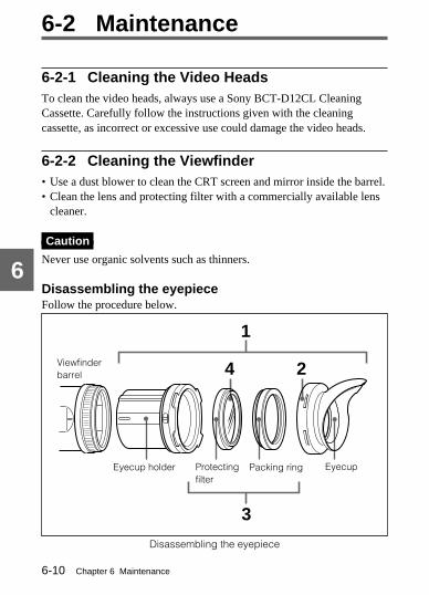
Chapter 6 Maintenance6-10
6
Eyecup holder EyecupPacking ringProtectingfilter
Viewfinderbarrel
6-2 Maintenance
6-2-1 Cleaning the Video HeadsTo clean the video heads, always use a Sony BCT-D12CL CleaningCassette. Carefully follow the instructions given with the cleaningcassette, as incorrect or excessive use could damage the video heads.
6-2-2 Cleaning the Viewfinder• Use a dust blower to clean the CRT screen and mirror inside the barrel.• Clean the lens and protecting filter with a commercially available lens
cleaner.
Caution
Never use organic solvents such as thinners.
Disassembling the eyepieceFollow the procedure below.
Disassembling the eyepiece
24
1
3

Chapter 6 Maintenance 6-11
6
1 Detach the eyepiece unit from the viewfinder.For more information, see Section 5-2-4 “Detaching the Eyepiece” (page5-15).
2 Remove the eyecup from the eyecup holder.
3 Remove the protecting filter together with the packing ring frominside the eyecup holder.
4 Detach the protecting filter from the packing ring.
Fog-proof filterDepending on the temperature and humidity, the protecting filter maymist because of vapor or your breath. To ensure that the viewfinder isalways clear, replace the protecting filter with a fog-proof filter (Part No.1-547-341-11, not supplied).
Fitting the fog-proof filterDetach the protecting filter from the packing ring, and replace it with thefog-proof filter.Be sure to correctly assemble the fog-proof filter, the packing ring, andthe eyecup so that the reassembled eyepiece is waterproof.
Note
When cleaning the fog-proof filter, wipe it very gently with a soft clothto avoid impairing the anti-fogging coating.

Chapter 6 Maintenance6-12
6
6-3 Operation WarningsWhen a problem occurs either at power on or during operation, warnings are givenby the WARNING indicator and tally indicator, in the display panel, and in theviewfinder. The speaker and earphone also give audible warnings.
Operation warningsDisplay panel Indicators Warning sound
Warning/indication
Flashing/continuous
: Continuous
: 1 flash/s.
: 4 beeps/s.: 1 beep/s.
: Continuous beep
WARNING REC/tally BATT
RF Continuous a) a)
SERVO Continuous
Continuous
HUMID Continuous a)
b)
SLACK Continuous
TAPE c) Flashing a) a)
TAPEand E
Continuous
BATT Flashing a)
BATTand E
Flashing
(Noindicationon thedisplaypanel)
a) During recording, b) During playback, fast forward, or rewind,c) Also “5-0” appears in the tape remaining displays.
: 2 flashes/s.
: 4 flashes/s.

Chapter 6 Maintenance 6-13
6
Problem VTR action Corrective action
Video head gapclogged or problem inrecording circuit.
After clogged head is detected,recording continues but issubstandard.
Clean the heads. If recording is stillsubstandard, turn off the power and consultyour Sony representative.
Servo lock lost. Recording continues but issubstandard.
Turn off the power and consult your Sonyrepresentative.Note that this indication may be givenmomentarily when the tape starts moving, butthis does not indicate a problem.
Interface errorbetween system CPUand servo CPU.
Recording continues but stops ifthe tape sticks to the head drum.Playback, fast forward, and rewinddo not operate.
Stop the tape, and wait until the HUMIDindicator disappears.
Condensation on thehead drum.
Recording continues but stops ifthe tape sticks to the head drum.Playback, fast forward, and rewinddo not operate.
Stop the tape, and wait until the HUMIDindicator disappears.
The tape cannot bewound properly.
VTR stops. An error code appearsin the counter display section ofthe display panel. Look up theerror code in the MaintenanceManual.
Remove the cassette by the method describedin the Maintenance Manual or by pressing theEJECT button several times. Close thecassette lid without loading a cassette. Turnoff the power and consult your Sonyrepresentative.
Near the end of tape. Operation continues. Be prepared to change the cassette.
End of tape. Record, playback, and fast forwarddo not operate.
Change the cassette or rewind the tape.
Low battery. Operation continues. Change the battery.
Dead battery. Operation stops. Change the battery.
Interface errorbetween system CPUand servo CPU.
Recording continues, but someoperations such as review andcuing do not operate.If another problem also occurs, itsindication is given priority.
Turn off the power and consult your Sony
representative.

Chapter 6 Maintenance6-14
6
Vertical tails show on the image.
Monitor screen
Bright object(mercury lamp, the sun, reflections, etc.)
Notes on CCD Image Sensors
Vertical smearSmear tends to be produced when an extremely bright object is beingshot; it is more likely to occur with a faster electronic shutter speed.
Vertical smear
AliasingWhen patterns of stripes or lines are shot, they may appear jagged.

Appendix A-1
A
SpecificationsPower voltage12 +–5
1..00 V
Power consumptionDVW-707/707P: 29 WDVW-709WS/709WSP: 31.5 WDVW-790WS/790WSP: 32 W(with 12 V DC supply, when recording)
Operating temperature0°C to 40°C (32°F to 104°F)
Operating humidity25% to 85% (relative humidity)
Storage temperature−20°C to +60°C (−4°F to +140°F)
MassApprox. 7 kg (15 lb 7 oz) (with lens, cassette and BP-L60A BatteryPack) A
ppendix

AppendixA-2
A
Dimensions
Dimensions in mm (inches)
Video Camera Section
General
ImagerDVW-707/707P/709WS/709WSP: 2/3-inch interline-transfer type Power
HAD CCDDVW-790WS/790WSP: 2/3-inch frame-interline-transfer typePower HAD CCD
Imager ConfigurationRGB, 3 CCDs
Spectral systemF 1.4 prism system (with quartz filter)
140
(5 5 /
8)
37 (1 1/2)
267
(10
5 /8 )
208
(8 1 /
8)
340 (13 1/2)
377 (14 7/8)

Appendix A-3
A
Built-in filtersDVW-707/707P:
ND filter1 : 3200K2 : 5600K + 1/8 ND3 : 5600K4 : 5600K + 1/64 ND
DVW-709WS/709WSP/790WS/790WSP:CC filterA: Cross filterB: 3200KC: 4300KD: 6300K
ND filter1: Straight through2: 1/4 ND3: 1/16 ND4: 1/64 ND
Electronic shutter speed1/100, 1/125, 1/250, 1/500, 1/1000, 1/2000 second (DVW-707/709WS/790WS)• CLS mode: 60.0 Hz to 10156 Hz in 263 steps (DVW-707)
60.1 Hz to 7000 Hz in 260 steps (DVW-709WS/790WS)
• ECS mode: 30.4 Hz to 58.3 Hz in 248 steps (DVW-790WS)• EVS mode: 1/60 second (DVW-707/709WS)• Super EVS mode: 1/60 second (DVW-790WS)1/60, 1/125, 1/250, 1/500, 1/1000, 1/2000 second (DVW-707P/709WSP/790WSP)• CLS mode: 50.0 Hz to 10101 Hz in 312 steps (DVW-707P)
50.2 Hz to 9000 Hz in 310 steps (DVW-709WSP/790WSP)• ECS mode: 25.4 Hz to 48.7 Hz in 295 steps (DVW-790WSP)• EVS mode: 1/50 second (DVW-707P/709WSP)• Super EVS mode: 1/50 second (DVW-790WSP)
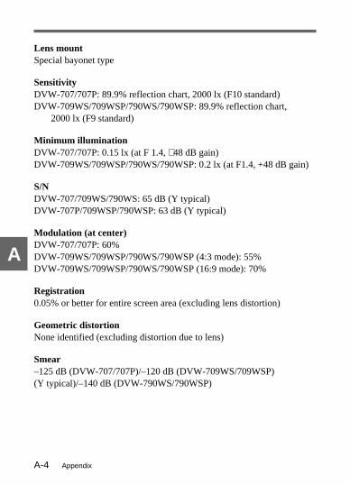
AppendixA-4
A
Lens mountSpecial bayonet type
SensitivityDVW-707/707P: 89.9% reflection chart, 2000 lx (F10 standard)DVW-709WS/709WSP/790WS/790WSP: 89.9% reflection chart,
2000 lx (F9 standard)
Minimum illuminationDVW-707/707P: 0.15 lx (at F 1.4, +48 dB gain)DVW-709WS/709WSP/790WS/790WSP: 0.2 lx (at F1.4, +48 dB gain)
S/NDVW-707/709WS/790WS: 65 dB (Y typical)DVW-707P/709WSP/790WSP: 63 dB (Y typical)
Modulation (at center)DVW-707/707P: 60%DVW-709WS/709WSP/790WS/790WSP (4:3 mode): 55%DVW-709WS/709WSP/790WS/790WSP (16:9 mode): 70%
Registration0.05% or better for entire screen area (excluding lens distortion)
Geometric distortionNone identified (excluding distortion due to lens)
Smear–125 dB (DVW-707/707P)/–120 dB (DVW-709WS/709WSP)(Y typical)/–140 dB (DVW-790WS/790WSP)

Appendix A-5
A
Viewfinder
CRT1 1/2-inch (DVW-707/707P) or 2-inch (DVW-709WS/709WSP/790WS/790WSP) monochrome, quick start type
Horizontal resolution (at center)DVW-707/707P: 600 TV linesDVW-709WS/709WSP/790WS/790WSP: 450 TV lines (16:9 mode)
600 TV lines (4:3 mode)The eyepiece on the DVW-709WS/709WSP/790WS/790WSP has a lowermagnification than the eyepiece on the DVW-707/707P.
VTR Section
General
Usable cassette tapes1/2-inch Digital BETACAM cassette tapes
BCT-D6/D12/D22/D32/D40
Tape speedApprox. 96.7 mm/s
Record/playback time40 minutes (using BCT-D40)
Fast forward timeApprox. 6 minutes (using BCT-D40)
Rewind timeApprox. 5 minutes (using BCT-D40)
Continuous recording timeApprox. 120 minutes (using BP-L60A)

AppendixA-6
A
Video (when using standard playback machine)
Bandwidth Luminance 0 to 5.75 MHz +−01..50 dB
Chroma (R-Y/B-Y) 0 to 2.75 MHz +−01..50 dB
S/N Luminance 62 dB min.
K factor (2T pulse) 1 % max.
Y/C delay 15 ns max.
Audio (when using standard playback machine)Frequency response 20 Hz to 20 kHz +
−01
.
.50 dB
Dynamic range 85 dB min.
Distortion 0.08% max.
Crosstalk 70 dB max.
Wow and flutter Below measurable level
Input/output connectors
Signal inputs
AUDIO IN CH-1/CH-2 (XLR, 3-pin, female)−60 dBu 1)/+4 dBu for DVW-707/709WS/790WS, or −60 dBs 2)/+4 dBsfor DVW-707P/709WSP/790WSP
MIC IN (XLR, 3-pin, female)−60 dBu for DVW-707/709WS/790WS, or −60 dBs for DVW-707P/709WSP/790WSP, with an external power supply system(48 V DC, maximum current 3 mA)
....................................................................................................................................1) 0 dBu = 0.775 Vrms.2) 0 dBs = 0.775 Vrms.

Appendix A-7
A
GENLOCK IN (BNC type)1.0 Vp-p, 75 ohms
TC IN (BNC type)0.5 V to 18 Vp-p, 10 kilohms
Signal outputs
VIDEO OUT (BNC type)1.0 Vp-p, 75 ohms, unbalanced
TEST OUT (BNC type)1.0 Vp-p, 75 ohms, unbalanced
AUDIO OUT (XLR, 5-pin, male)0 dBm
TC OUT (BNC type)1.0 Vp-p, 75 ohms
EARPHONE (minijack)8 ohms, −∞ to −18 dBu (or −18 dBs) variable
Others
DC IN (XLR, 4-pin, male)11 to 17 V DC
DC OUT (4-pin)11 to 17 V DC, maximum current 0.1 A
LENS (12-pin)
REMOTE (8-pin)

AppendixA-8
A
....................................................................................................................................1) Maintenance Manual Part 1
This manual gives the information necessary for users to maintain the camcorderand its optional equipment.
Supplied AccessoriesMicrophone (super cardioid directional, external power supply type) (1)Shoulder strap (1)Operation Manual (1)Maintenance Manual Part 1 1) (1)
Recommended Additional Equipment
Power supply and related equipmentBP-L60A/L90A Battery PackNP-1B Battery PackBP-90A Battery PackBC-L100/L100CE Battery Charger (for BP-L60A/L90A)BC-1WD/1WDCE Battery Charger (for NP-1B)BC-210/210CE Battery Charger (for BP-90A)BC-410/410CE Battery Charger (for NP-1B/BP-90A)DC-L1 Battery Adaptor (to hold an NP-1B)DC-L90 Battery Adaptor (to hold a BP-90A)AC-550/550CE AC AdaptorAC-DN1/DN2A AC Adaptor
Setup cardBSC-1-Pack (Four BSC-1s with a setup card holder)
Digital BETACAM cassette tapesBCT-D60/D12/D22/D32/D40
Viewfinder and related equipmentBVF-VC10W Color Viewfinder

Appendix A-9
A
Fog-proof filter (Part No. 1-547-341-11)Lens assembly (farsighted) (−2.8 D to +2.0 D) (Part No. A-8262-537-A)Lens assembly (low magnification) (−3.6 D to −0.8 D) (Part No.A-8262-538-A)Lens assembly (standard magnification with special compensation foraberrations) (−3.6 D to +0.4 D) (Part No. A-8267-737-A)Lens assembly high performance (3 × magnification) (–2.4 D to +0.5 D)(Part No. A-8314-798-A)
Optical attachmentsND filter (1/4 ND) (Part No. 3-194-480-01)ND filter (1/16 ND) (Part No. 3-194-481-01)Cross filter (Part No. 3-174-682-01)Mount ring (Part No. 3-186-442-01)Consult your Sony representative for more infomation about these filters.
Equipment for remote controlRM-B150 Remote Control UnitRM-P9 Remote Control Unit (requires CCA-86-0.4 conversion cable)BVR-3 Remote Control UnitVA-DN1 Camcorder Interface Adaptor
Audio equipmentC-74 microphoneECM-MS5 stereo microphoneCAC-12 Microphone HolderCRS-3P Cradle SuspensionWRR-28H/28M/28L/810A/860A UHF Portable TunerWRT-27 UHF TransmitterBTA-27 UHF Portable Tuner Attachment Kit
Equipment for maintenance and easier handlingBCT-D12CL Cleaning CassetteLC-777 Carrying Case

AppendixA-10
A
....................................................................................................................................1) Maintenance Manual Part 2
This manual gives the additional information to fully maintain the comcorder. Itcontains details of adjustments that can be made, cirduit diagrams, etc.
LC-304SFT Soft Carrying CaseRain coverWRR Tuner Fitting (service part number: A-8278-057-A)VCT-14 Tripod AdaptorMaintenance Manual Part 2 1)
Design and specifications are subject to change without notice.

Appendix A-11
A
GlossaryAliasingDistortion of the signal caused by overlap of the baseband signal and thelower sideband signal when the signal is demodulated.
ATWAuto Tracing White balance. The white balance is automaticallyadjusted for the lighting conditions during shooting.
Bayonet mountA type of lens mount. The lens can be inserted into the lens mount andquickly locked in place by simply rotating the lens locking ring.
Black balance adjustmentTo balance the black levels of the R, G, and B channels of a videocamera so that black has no color.
Black setA reference level for black balance adjustment.
CCDCharge-Coupled Device. A solid state imager used in most videocameras in place of a pickup tube. The device converts input light levelsinto electrical charges that are first stored and then output in the form ofvoltage variations.
Center markerA cross which indicates the center of the image on the viewfinder screen.
Color bar signalA test signal which can be displayed as vertical bars of different colorson a color video monitor. This signal is used to check chrominancefunctions of color television and video systems such as cameras andmonitors.

AppendixA-12
A
Color temperatureThe temperature in Kelvins (K) to represent the color of a light source,determined by heating a perfectly black body until its color matches thatof the light source. Color temperature is higher when the color is bluishand lower when reddish.
CondensationMoisture condensation on the VTR tape transport mechanism.Condensation on the head drum causes tape to stick to the drum,resulting in damage to tape and a malfunction of the VTR.
CRTCathode-Ray Tube. Video camera viewfinders are equipped with a CRTimage display, so you can monitor what you are shooting.
CTLControl signal in the form of regular pulses recorded along a longitudinaltrack on the video tape. By counting these pulses, it is possible todetermine the number of frames, and hence the tape running time. Usedmainly to adjust the tracking position of video heads, and to achieve timecode continuity in continuous recording.
DCCDynamic Contrast Control. A video camera containing a DCC circuit canhandle a wide dynamic range of luminance.
DiopterA measure of lens power ; its unit is the reciprocal of 1 m (3.28 ft). Adiopter lens is a simple supplementary lens placed over the main cameralens to alter its effective focal length.

Appendix A-13
A
Drop frame modeSMPTE time code runs at 30 frames/second, while the NTSC colortelevision system runs at about 29.97 frames/second. This means that alength of 1 hour as indicated by time code is longer than the actual clocktime of 1 hour by 108 frames, or about 3.6 seconds. Drop frame modeadjusts the running of time code to eliminate this discrepancy bydropping two frames from the time code value at the beginning of eachminute except every tenth minute. In contrast, non-drop frame modedoes not adjust the discrepancy between time code value and actual time.
EBUEuropean Broadcasting Union. Established by broadcasting and relatedorganizations in Europe.
E-E modeElectric-to-Electric mode. When you operate a VTR in E-E mode, inputvideo and/or audio signals pass through electric circuits only and thencome out from the output connectors, without passing throughelectromagnetic conversion circuits such as recording heads. You canuse E-E mode to directly check and monitor the input signals withoutrecording them on tape.
EFPElectronic Field Production. The use of electronic equipment such asportable video cameras, VTRs, and sound equipment for televisionproduction outside studios.
ENGElectronic News Gathering. The use of electronic equipment such asportable video cameras, VTRs, and sound equipment for the productionof daily news stories and short documentaries.
FfSee Flange focal length.

AppendixA-14
A
FITFrame Interline Transfer. A type of CCD imager featuring substantiallyreduced vertical smear. See also CCD and Vertical smear.
Flange focal lengthThe distance from the plane of lens mounting flange to the image focalplane. Abbreviated to Ff.
FlareDark or colored flashes caused by signal overload through extreme lightreflections of polished objects or very bright lights.
FlickerRepeated change of brightness on the screen.
GenlockGenerator lock. To synchronize the pulse generator built into videoequipment to an external reference (master) sync signal.
Geometric distortionAny change in geometry or perspective of the reproduced image from theoriginal.
HADHole-Accumulated Diode. A CCD sensor structure designed to suppresscertain types of noise inherent to CCDs. See also CCD.
Horizontal resolutionThe capability of a video camera or a display unit to preserve detail inthe horizontal direction. Usually expressed as the number of verticallines which can be distinguished in the reproduced image of a test chart.

Appendix A-15
A
HuntingRepeated brightening and darkening of an image resulting from repeatedresponse to automatic iris control.
IRE scaleThe scale to determine video signal amplitudes devised by the Instituteof Radio Engineers (IRE), an American organization now called theInstitute of Electrical and Electronic Engineers (IEEE).
ITInterline Transfer. A type of CCD imager.
LTCLongitudinal Time Code. A time code recorded along the tape in theforward direction of a tape run. A VTR cannot reproduce LTC when taperun stops to output a still picture. The output level of LTC is very lowwhen tape runs slowly, so an LTC read error is likely to occur while theVTR is playing back in slow motion. See also Time code and VITC.
ND filterNeutral Density filter. ND filters reduce the amount of incident lightequally across the entire visible wavelength range without affectingcolor.
R/G mixing detail circuitA circuit used to mix R and G signals to obtain a Y signal so that a sharppicture is reproduced.
Reference video signalA video signal that contains a sync signal or sync and burst signals, usedas a reference for synchronization of video equipment.

AppendixA-16
A
Sawtooth waveformA form of signal resembling the teeth of a saw. A video signal having asawtooth waveform is used to check linearity and other characteristics ofvideo amplifiers.
Shot dataData recorded, while shooting, in the color bars, the U-BIT data of theVITC, and so forth. Includes the model name, serial number, date, time,shot number, cassette number, and ID1 to ID4.
Shutter speedThe length of time for which the shutter stays open. The higher theshutter speed, the more clearly a moving object can be shot.
SmearSee Vertical smear.
SMPTESociety of Motion Picture and Television Engineers, a professionalassociation established in the U.S.A. mainly for the purpose of settingforth motion picture and television engineering standards.
S/NSignal-to-Noise ratio. The relation of the strength of the desired signal tothe accompanying electronic interference, the noise. If S/N is high,sounds are reproduced with less noise and pictures are reproducedclearly without snow.
Time codeA digitally encoded signal which is recorded on video tape to identifyeach frame of video by hour, minute, second and frame number. SMPTEtime code is applied to NTSC system, and EBU time code to PAL andSECAM systems. There are two kinds of recorded signals : longitudinaltime code (LTC) and vertical interval time code (VITC). See also LTCand VITC.

Appendix A-17
A
Time code synchronizationTo synchronize the built-in time code generator of video equipment suchas a VTR to an external time code.
Turbo gainVideo amplifier gain boosted from 30 dB to 36 or 42 dB by combiningblocks of 2 or 4 adjacent pixels of the CCD.
User bitsA total of 32 bits are provided in the time code which the user can use torecord such information as date, scene number, or reel number on videotape.
Vertical smearA bright vertical line which appears on the screen when shooting a verybright object with a CCD camera. Also called smear.
Video gainAmount of amplification for video signals, expressed in decibels (dB).
VITCVertical Interval Time Code. A time code recorded on video tape in twohorizontal lines during each vertical blanking period of a video signal.Unlike LTC, VITC is recorded in the same tracks as the videoinformation, so they can be read even while the tape is not moving. Seealso Time code and LTC.
White balance adjustmentIn the light of a particular color temperature, to adjust the white levels ofthe R, G, and B channels of a color video camera so that any white objectshot in that light is reproduced as a truly white image. See also Colortemperature.

AppendixA-18
A
White shadingWhen shooting a white object, the upper and lower portions of the screenmay appear magenta or green while the central portion appears white,depending on the performance of the camera lens. This is called whiteshading.
Zebra patternIn a video camera, striped patterns which appear in the viewfinder screento indicate areas of the image where the video level is higher than acertain value. If a zebra pattern appears on the skin when the object is ahuman being, that is a correct exposure.
ZoomTo gradually change the field of view of a camera lens from wide tonarrow angle (zoom in) or narrow to wide angle (zoom out).

Index I-1
A
testing the audio functions6-7
AUDIO IN CH-1/CH-2 connectorsand LINE/MIC/+48 V ONselectors 2-9AUDIO IN switches 2-8AUDIO LEVEL CH-1/CH-2controls 2-8AUDIO OUT connector 2-9Audio level indicator 4-56AUDIO SELECT CH-1/CH-2switches 2-8AUTO W/B BAL switch 2-22,4-3, 4-8Automatic iris
closing 4-21opening 4-21
BBATT indicator 4-49Battery
Anton Bauer IntelligentBattery System 5-9state indicator 4-55
Battery adaptorDC-L1 1-7, 5-4DC-L90 1-7, 5-6
Battery attachment 2-1Battery charger
BC-1WD/1WDCE 1-7, 5-4BC-210/210CE/410/410CE 1-7, 5-5BC-L100/L100CE 1-7, 5-1
IndexAAC-550/550CE AC Adaptor 1-7,5-8Accessories A-8Accessory attachments 2-3AC-DN1/DN2A AC Adaptor 1-7,5-8Adjustment and settings forrecording
audio level 4-24black balance and whitebalance 4-1electronic shutter 4-13reference value for automaticiris adjustment 4-21time data 4-27setting color temperaturemanually 4-91specifying an offset for theauto white balance setting 4-93
ADVANCE button 2-32ALARM volume control 2-10Anton Bauer Intelligent BatterySystem 5-9Anton Bauer Ultralight System5-9Audio
level adjustment 4-25level meter 2-38, 4-24line input from audioequipment 5-33

IndexI-2
A
Battery packBP-90A 1-7, 5-5BP-L60A/L90A 1-7, 5-1NP-1B 1-7, 5-4
BC-1WD/1WDCE BatteryCharger 1-7, 5-4BC-210/210CE/410/410CEBattery Charger 1-7, 5-5BC-L100/L100CE Battery Charger1-7, 5-1BETACAM holder kit 5-31BKW-401 Viewfinder RotationBracket 1-6, 5-14Black balance and black setadjusting
error messages 4-4memory 4-5
BP-90A Battery Pack 1-7, 5-5BP-L60A/L90A Battery Pack 1-7,5-1BREAKER button 2-2BRIGHT control 2-15BSC-1 Setup Card 1-6, 4-113Built-in speaker 2-13BVR-3 Remote Control Unit 1-6,2-9
CC-74 microphone 1-7, A-9CA-701/702 Camera Adaptor 1-3,1-6
CA-755 Camera adaptor 1-6CAC-12 Microphone Holder 1-7,5-24Camera adaptor See “CA-701/702/755 Camera Adaptor” above.Cameraman tally indicator 2-16CAMERAMAN menu 4-95Camera section
features 1-1specifications A-2testing 6-3
Carrying casestoring the camcorder 5-10
Cassette numberindicator 4-54setting 4-37
Cassette tapeloading 3-1preventing accidental erasure3-4slack checking 3-3unloading 3-3usable cassettes A-5
CC (Color temparatureConversion) filter 2-19, 4-7CCD image sensor
notes on CCD image sensor6-14
CleaningBCT-D12CL CleaningCassette 6-10video heads 6-10viewfinder 6-10
CLS mode 4-13, 4-17

Index I-3
A
Color playback 3-19Condensation 6-2Continuous recording 3-9CONTRAST control 2-15Cradle suspension (CRS-3P) 5-24CTL 2-32, 2-41
DDC IN connector 2-1DC-L1 Battery Adaptor 1-7, 5-4DC-L90 Battery Adaptor 1-7, 5-6DC OUT connector 2-9DCC (Dynamic Contrast Control)2-21DF/NDF switch 2-33DIAG button 2-36Diopter adjustment ring 2-16,5-12Display
display mode and message4-61indicators 2-38markers 4-64setup menu 4-44status 2-38warnings 2-38
Dynamic Contrast Control 2-21
EEarphone
testing 6-8EARPHONE jack 2-13ECS mode 4-14E-E sound 2-13
EJECT button 2-26Electronic shutter
See shutter.Error messages
about black balanceadjustment 4-4about setup card operation4-120, 4-123about white balanceadjustment 4-10
EVS mode 4-14Extender indicator 4-54External microphone
using 5-23testing 6-8
Eyecup 2-14, 6-10Eyepiece
detaching and reattaching5-15disassembling 6-10
FF FWD button and indicator 2-26Filter
CC filter 2-19, 4-7fog-proof filter 1-6, 6-11indicator 4-57ND filter 2-19, 4-7protecting filter 6-10selecting filter 2-18, 4-7
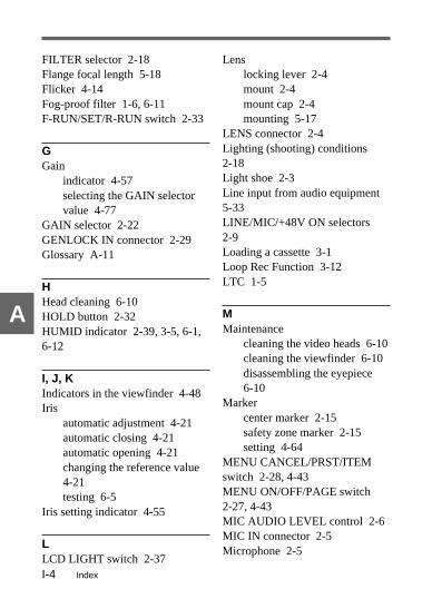
IndexI-4
A
FILTER selector 2-18Flange focal length 5-18Flicker 4-14Fog-proof filter 1-6, 6-11F-RUN/SET/R-RUN switch 2-33
GGain
indicator 4-57selecting the GAIN selectorvalue 4-77
GAIN selector 2-22GENLOCK IN connector 2-29Glossary A-11
HHead cleaning 6-10HOLD button 2-32HUMID indicator 2-39, 3-5, 6-1,6-12
I, J, KIndicators in the viewfinder 4-48Iris
automatic adjustment 4-21automatic closing 4-21automatic opening 4-21changing the reference value4-21testing 6-5
Iris setting indicator 4-55
LLCD LIGHT switch 2-37
Lenslocking lever 2-4mount 2-4mount cap 2-4mounting 5-17
LENS connector 2-4Lighting (shooting) conditions2-18Light shoe 2-3Line input from audio equipment5-33LINE/MIC/+48V ON selectors2-9Loading a cassette 3-1Loop Rec Function 3-12LTC 1-5
MMaintenance
cleaning the video heads 6-10cleaning the viewfinder 6-10disassembling the eyepiece6-10
Markercenter marker 2-15safety zone marker 2-15setting 4-64
MENU CANCEL/PRST/ITEMswitch 2-28, 4-43MENU ON/OFF/PAGE switch2-27, 4-43MIC AUDIO LEVEL control 2-6MIC IN connector 2-5Microphone 2-5

Index I-5
A
microphone holder (A) 5-24microphone holder (CAC-12)1-7, 5-25using an external microphone5-24using the supplied microphone5-20
Monitor 1-6, 3-20See also Playback.
MONITOR switch 2-11MONITOR volume control 2-11
NND (Neutral Density) filter 2-19,4-7NP-1B Battery Pack 1-7, 5-4
See also Battery and PowerSupply.
OOperation status warning
indicator 4-49setting 4-50
Operation warnings 6-12OUTPUT/DCC selector 2-21
P, QParts and controls
accessory attachments 2-3audio functions 2-5power supply 2-1setup menu operating section2-27
shooting and record/playbackfunctions 2-14time code system 2-29warnings and indications2-35, 2-38
PEAKING control 2-15PLAY button and indicator 2-26Playback 3-19
checking the recording 3-19color playback 3-20parts and controls 2-14recording review 3-19using a color video monitor 3-20
Power supplyAC adaptor 1-7, 5-8Anton Bauer IntelligentBattery System 5-9battery pack (BP-90A)1-7, 5-5battery pack (BP-L60A/L90A)1-7, 5-1battery pack (NP-1B)1-7, 5-4parts and controls 2-1See also Battery.
POWER switch 2-2Precautions 1-8PRESET/REGEN switch 2-33Protecting filter 6-10
RRain cover 5-39REC indicator 4-49

IndexI-6
A
Recordingbasic procedure 3-5cassette tape 3-1, A-8checking the recording 3-20continuous recording 3-9Loop Rec Function 3-12parts and controls 2-14recording pause 3-9reversing the pictureorientation 3-18
Recording review 3-19Recording run mode 2-33, 4-30Reference video signal 4-32Remaining tape indicator 4-55Remote control 5-42
remote control unit (BVR-3)1-6, 2-9remote control unit (RM-B150/RM-P9) 1-6, 4-23, 5-42
REMOTE connector 2-23RESET button 2-32REW button and indicator 2-26RF indicator 2-39, 6-12RM-B150 Remote Control Unit 1-6, 4-23, 5-42RM-P9 Remote Control Unit 1-6,4-23, 5-42Rotary encoder 2-27
SSafety zone marker 2-15Selecting the functions 4-79Selecting the display items 4-58Self-diagnosis indicator 4-55
SERVO indicator 2-39, 6-12Setting up
adjusting the flange focallength 5-18adjusting the shoulder padposition 5-38adjusting the viewfinder 5-10attaching shoulder strap 5-36audio input system 5-20carrying case 5-10connecting a remote controlunit 5-42mounting the lens 5-17power supply 5-1putting on the rain cover 5-39tripod mounting 5-34
Setup card 4-113handling 4-113setting the card ID 4-124using data 4-115
Setup card compartment 2-27Setup menu
basic use 4-43FUNCTION 1/2 page 4-40, 4-84FUNCTION 2/2 page 4-40, 4-79MARKER 1/3 page 4-39,4-64MASTER GAIN page 4-40,4-77menu configuration 4-39menu operating section 2-27

Index I-7
A
OPERATION 2 page 4-74SETUP CARD page 4-40,4-113SHOT DISP. page4-40, 4-67SHOT ID page 4-40, 4-69SHUTTER page4-19, 4-40VF DISP 1/2 page 4-39,4-59VF DISP 2/2 page 4-40, 4-59WIDE SCREEN page 4-40,4-85‘!’ LED page 4-40, 4-50
SHIFT button 2-32Shooting 3-7
shooting conditions 2-18See also Recording.
Shot data 4-66recording in the VITC userbits 4-110
Shot ID 4-69Shot number
AUTO SHOT NO. RESET4-103indicator 4-55setting 4-37
Shoulder pad 2-4adjusting the position 5-38
Shoulder strap attaching 5-36Shoulder strap posts 2-3Shutter
changing the shutter setting4-19selecting mode and speed4-15setting the electronic shutter4-13shutter modes 4-13
SHUTTER selector 2-22Shutter speed and mode indicator4-56SLACK indicator 2-39, 6-12Spare indicators 4-49Speaker 2-13
testing 6-8Specifications A-1STOP button 2-26Storing the camcorder 1-8, 5-10System configuration 1-6
TTally
cameraman tally indicator2-16indicators 2-36
TALLY switch 2-36Tape
remaining tape indicator4-55remaining tape time 4-55TAPE status indicator 2-38,6-12testing the tape transportfunctions 6-6

IndexI-8
A
See also Cassette tape.TC IN connector 2-29TC OUT connector 2-30Testing the camcorder beforeshooting
audio level adjusting functions6-7camera section 6-3earphone 6-8external microphones 6-8iris function 6-5preparations for testing 6-1speaker 6-8tape transport functions 6-6time code function 6-9user bit function 6-9viewfinder 6-3VTR section 6-6zoom function 6-5
Test outputselecting information to output4-73synchronizing 4-32
TEST OUT connector 2-24, 2-30,4-33Time code
displaying 2-32, 2-40resetting 2-32setting 4-29synchronizing 4-32testing 6-9
Time code indicator 4-57Time counter display 2-40Time data
displaying 2-32, 2-40resetting 2-32setting 4-27synchronizing 4-32
Tripod mount 2-4Tripod mounting 5-34
tripod adaptor 5-34Turbo gain 2-20, 4-77
UUHF portable tuner (WRR-28H/28M/28L/810A/860A) 1-7,5-28User bits
displaying 2-32, 2-40resetting 2-32setting 4-27storing the setting in memory4-28testing 6-9
VVideo
gain selecting 4-77head cleaning 6-10monitor 1-6, 3-20TEST OUT connector 2-24,2-30, 4-33VIDEO OUT connector 2-23,4-33
Viewfinder 2-15, 5-10adjusting the diopter 5-12adjusting the position 5-11adjusting the screen 5-12cleaning 6-10

Index I-9
A
detaching 5-13detaching and reattaching theeyepiece 5-15diopter adjustment ring 2-16,5-12front-rear positioning lever2-16, 5-11left-right positioning ring2-16, 5-10rotation bracket (BKW-401)1-6, 5-14screen displaysSee Display.selecting information todisplay 4-75specifications A-5stopper 2-16, 5-13testing 6-3
VITC 1-5VTR
features 1-4operation and status indicators2-39specifications A-5testing 6-6
VTR SAVE indicator 4-50VTR SAVE/STBY switch 2-26VTR START button 2-25
W, X, YWARNING indicator 2-37Warning and indications
display panel indications 2-38
operation warnings 6-12parts and controls 2-38viewfinder screen displays4-53, 6-12warning sound 2-10, 6-12See also Display.
WHITE BAL switch 2-20, 4-6White balance
adjusting 4-5error messages 4-10memory 4-11
White balance memory indicator4-57WRR-28H/28M/28L/810A/860AUHF Portable Tuner 1-7, 5-28
ZZebra pattern 2-15ZEBRA switch 2-16Zoom
zoom position indicator 4-54zoom testing 6-5


Name
Office
Address
Phone

The material contained in this manual consists of information thatis the property of Sony Corporation and is intended solely for useby the purchasers of the equipment described in this manual.Sony Corporation expressly prohibits the duplication of any portionof this manual or the use thereof for any purpose other than theoperation or maintenance of the equipment described in thismanual without the express written permission of SonyCorporation.
Le matériel contenu dans ce manuel consiste en informations quisont la propriété de Sony Corporation et sont destinéesexclusivement à l’usage des acquéreurs de l’équipement décritdans ce manuel.Sony Corporation interdit formellement la copie de quelque partieque ce soit de ce manuel ou son emploi pour tout autre but quedes opérations ou entretiens de l’équipement à moins d’unepermission écrite de Sony Corporation.
Das in dieser Anleitung enthaltene Material besteht ausInformationen, die Eigentum der Sony Corporation sind, undausschließlich zum Gebrauch durch den Käufer der in dieserAnleitung beschriebenen Ausrüstung bestimmt sind.Die Sony Corporation untersagt ausdrücklich die Vervielfältigungjeglicher Teile dieser Anleitung oder den Gebrauch derselben fürirgendeinen anderen Zweck als die Bedienung oder Wartung derin dieser Anleitung beschriebenen Ausrüstung ohne ausdrücklicheschriftliche Erlaubnis der Sony Corporation.

Sony CorporationB & P Company
Printed in Japan2002.03.13 1999
DVW-707/707PDVW-709WS/709WSPDVW-790WS/790WSP (SY)
3-865-903-03(1)