cdheqa/sl-997 - welcome to nasa headquarters | …...magazine film must be loaded and unloaded in a...
TRANSCRIPT

i'1k 1'
?
D
-_;'1 Y
4;
HANDBOOK
OF
PILOT OPERATIONAL EQUIPM NT
FOR
MANNED SPACE FLIGHT
Report No.
CDHEQA/SL-997
Prepared By
POE Development Section
Crew Equipment and Design Branch
Flight Crew Integration Division
National Aeronautics and SpaceAdministranbn
LYNDON B. JOHNSON SPACE CENTER
Houston, Texas
JUNE 1973

16 mm. Seguence Camera System
Right Angle UniversalMirror - 2.12
FMount _ 2_1g
I ILenses |
5 mm. - 2.5 18 mm. - 2.7io mm. 2.6 75 mm. - 2.9 I DAC Power
25 mm. 2.8 100 mm. - 2.10|
Pack - 2.171
180 mm. - 2.11'
II
DAC Film DAC - 2.1 DAC EVAI
Magazine (1M0)_I
Bracket - 2.19 I- 2.2 I
,I
|I
__ _I
|I
DAC Transport JMech. - 2.3 þÿ�V �
"' "
DAC Handle - 2.20
I I
II
I
I Spare Fuse - 2.15I
DAC Filmþÿ �
RCU Bracket - 2.21
Cassette
I
L_Remote Control
Cable - 2.16
, Bight Angle Adpt.
Power Cables Bracket - 2.22
(CM) - 2.13
(SWS) _ 2_luWedge Bracket - 2.23
Spotmeter - 6.1
Ring Sight - H.15
2.0-1


2.1 Data Acquisition Camera (DAC) (SEB33100100):
The 16 mm. Data Acquisition Camera (DAC) is used to obtain
sequential photographic data during manned space flightmissions. Unlike typical movie cameras, this unit has
independent shutter speeds and framing rates. Furthermore,the automatic frame rates are lower than the common cine
speeds to maximize film usage while maintaining the desired
engineering data value. The DAC can be handheld or bracket
mounted, can operate from spacecraft or portable battery
power, and can accept various lenses and assorted accessories
as described in the following sections of this handbook.
2.1.1 Significant Configurations:
Configuration Purpose
-211 Skylab flight unit; 2 fps mode
instead of 1 fps ~
-216 Skylab support unit; 2 fps mode
instead of 1 fps
-217 Apollo CM and LM flight unit
-218 Apollo lunar surface flight unit;operate light hood incorporated
2.1.2 Characteristics:
- Manufactured by J. A. Maurer, Inc., Long Island City,New York 11101.
- weight - l.7 lbs (771 g.)Envelope - 6 X 3.75 X 2.u in. (15.2 X 9.5 X 6.1 om)Volume - 5M in3 (885 cm3) X
- Power requirements: 28 i M VDC at 0.6 amps nominal from
spacecraft or DAC Power Pack (see 2.17). DAC incorporatesself-resetting overload protection circuit and replaceablepower 1ine fuse (1.5 or 2.0 amp) (see 2.15).
'
Sequencing frame rate settable to 1 (or 2), 6, 12, or
2M frames per second (fps) and time exposure.
Automatic Modes [1 (or 2), 6, and 12 fps] are initiated
by depressing and releasing camera front button and continue
uninterrupted even if sequencing rate is changed amoung
automatic modes. Camera operation is stopped by depressingand releasing frontbutton. or by switching to the time
exposure or 2M fps mode settings. Green operate light will
flash at frame rate.
2.1-1

"E=§Q,:Z` `
2 ¢»
þÿ ��F_ -,_= __=:_=_
§@§;&¢w*-
:K
_.\~
_ V
~ _
_x\
`
,
I l 'Q H S ML maxi nl_ _
þÿ ��'
_
þÿ �
þÿ�_� �~ ��:�_�§�»�s�;�>�`�=�_s W
`
2 __ _
°
~ T 1 N f\;,;
`
§ _
_ _"!s=- ~ _ ; 3 _gk _;
:;»_ _
`
>__ élxggé# þÿ ��_�_`
- ~-
»
Q' .- s þÿ ��N ~' f" §
»
' þÿ ��» ~
4,3 .1 X, 35. :ees ww; _
=
'
F) . G* *_ _ _ _ i ; > ~ ~~;~~~< _.» _ _.» _
»=
'
_ 13 ag .-f ~ _ _
* g =§ f' þÿ �
jx _L§$;;_?f_ _ \_» .* þÿ � ~ ~` `
@§;f%§§ ~ H» "@§§_ %@@Z »;~_~ $ ?&#f _ x» w@§% §§§§ i@W ~;#
J%¥~_ > _@%_§§@§§@ iw
'
"" _
f* P _~- :_ _» þÿ � ��>�`�;�b�2�_
"""`
'
_ii~~§s¢:>i°% ""`
_
~
-3 þÿ � "iw $11511 þÿ�, ��=�_�Z�.�-�, _ þÿ�m�m�f � F _JUVQ@dLl _,@Q% Q, _@@§; `§;_
K' _wi~ *
»
_
þÿ �
== ~~'
þÿ ��§�§�&�§�%�%�%�§ , @§@@§%W~@#þÿ�r �
, _
Figure 2.1 _1_
2.1
'-_§;1»§§;_:§\f=_ a _=s=--`
*Y §f þÿ� �=� ��s�E�S�5�Z�*�@�2 ��i�e�=�;�_�_�-�$�3 *
ww sw _ > ______ _ _
_
þÿ �
2
QW"
U,
-..>,__ _fill H §_ .
Data Acquits ition Camera
Back, Top,View
and Front
2

,LJ
9-;
» x,__
U
Q3» 'Q
IC
W4
,~\
gn
5 K
Q),,,
/
,Ti_~
A .
LC
--x
,V
51'
15,
(JL
,A
Q
¥
4
W ip.
5:3 iii Q i
:ap .M
4;, .;.> D1 .J
Q G3 if
,bi Ez?N þÿ�f � 5_1 A#
<_
§ ii Sf
R {`
ii Q#fi U-f, rx
if
gi ffQ;
þÿ ��' �
E,Q
. 3:3 QEA-< Ly"
; i _*K* Q
. 1
;»é§w;=¢¢w;¢'»fif;»§,_ L,We w
`
;,-F »
i '*;, i+
þÿ ��l \»
Jw
f i
Qi
w
Im N
aiS,
v~,I '
'
Q.)'
~~
iw _r .
~~~ é&N§TTW@%i
i
§
< _,Q ,Qty'H
b____
Y 5? i§a u.éfjf §
v'n/ i§` ~
n/- *5i 3
EL)i ij 3 U i.
Lil = J; C,. Q þÿ ��g�i £3 ;'$~ Q in fi)
þÿ ��` ;i
aj1 5?
WL*
15 ;~;..... ,_ =
E; M
43
"ff þÿ � f kdS4
Q> M® 5.
* '
if ff(_'§ .4
\/~
2. 1-3
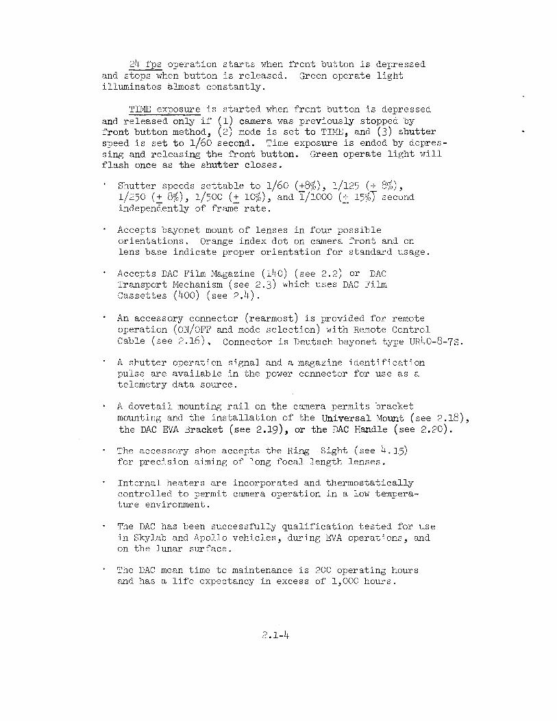
2M fps operation starts when front button is depressedand stops when button is released. Green operate lightilluminates almost constantly.
TIME exposure is started when front button is depressedand released only if (l) camera was previously stopped byfront button method, (2) mode is set to TIME, and (3) shutter
speed is set to l/60 second. Time exposure is ended by depres-sing and releasing the front button. Green operate light will
flash once as the shutter closes.
'
Shutter speeds settable to l/60 (i8%), l/l25 (+ 8%),1/250 (i 8%), 1/500 (i lO%), and 1/iooo (i i5%T second
independently of frame rate.
°
Accepts bayonet mount of lenses in four possibleorientations. Orange index dot on camera front and on
lens base indicate proper orientation for standard usage.
°
Accepts DAC Film Magazine (lMO) (see 2.2) Or DAC
Transport Mechanism (see 2.3) which uses DAC Film
Cassettes (Moo) (see 2.M).
° An accessory connector (rearmost) is provided for remote
operation (ON/OFFand mode selection) with Remote Control
C&bl@ (SGS 2-16). Connector is Deutsch bayonet type URMO-8-73
'
A shutter operation signal and a magazine identification
pulse are available in the power connector for use as a
telemetry data source.
- A dovetail mounting rail on the camera permits bracket
mounting and the installation of the Universal Mount (See 2.18the DAC EVA Bracket (see 2.19), or the DAC Handle (see 2.20).
° The accessory shoe accepts the Ring Sight (see M.J5)for precision aiming of long focal length lenses.
' Internal heaters are incorporated and thermostaticalkycontrolled to permit camera operation in a low tempera-ture environment.
' The DAC has been successfully qualification tested for use
in Skylab and Apollo vehicles, during EVA operations, and
on the lunar surface.
' The DAC mean time to maintenance is 200 operating hours
and has a life expectancy in excess of l,OOO hours.
2.1-M

2 2 DAC Film Magazine (iuo) (SEB33lOOl25):
The 16 mm. DAC Film Magazine (lHO) is the original film
magazine for the DAC system. The capacity of this magazine
is limited to lMO feet of thin base 16 mm. film.
2.1 Significant Configurations:
Configuration Purpose
-203 or -205 Apollo CM flight unit
-20M Apollo lunar surface flight unit;white thermal coating on lid
-206 Skylab flight unit
2.2 Characteristics:
- Manufactured by J. A. Maurer, Inc., Long Island City,
New York lllOl.
- weight - 1.0 lb (u5u g. > with film.
Envelope - 3.6 X 5.M X 0.9 in (9.2 X 13.7 X 0.23 cm).Volume - 17.5 in3 (287 @m3).
. Film capacity of lMO feet (M2.7 meters) of thin base film
(2.5 mil, 6M pm) provides maximum run durations of
93 min at l fps, M6 min at 2 fps, 16 min at 6 fps,8 min at 12 fps, and M min at 2M fps.
° Magazine film must be loaded and unloaded in a photographicdarkroom.
' Film usage indicator shows the gross amount of film
remaining.
þÿ � The red light at the rear of the magazine illuminates
when 6 feet (1.8 meter) of film remains. The light
remains energized and the camera continues to run when
the film supply is depleted.
' This film magazine has been qualified to the same levels
as the DAC (see 2.1).
2.2-l

D
(4 A
§`If
þÿ ��Z,,
6
:lim
1mdiQ&tor s #1 "
» % i
I_ _ þÿ ��_�:�5�`�2�`�;
A'
,W þÿ ��W `
i%i»_@&~ þÿ ��.�"�~�°�»þÿ ��N
þÿ�@�c�m�m�@�Q ¬faa Fm(-C -wi þÿ �
N þÿ�»�< �:wuswx
y 3l `
"».
a*
~
þÿ�i�t�h � "' JC 1 f lf" I 'fvfn flyfalt {";p_
Nuie
i,`,, ai
J :"35:E?'§§ ="'¥ :SF-=7 `'
þÿ�=�=� �E�=�"� �� ��! ��5�=�!�§�§�E�§�`�§�Z�.�»�"�-�= >»
Im .. "... _,
1: '
_f~~_~f» `@%%www@@¥ii®@§@w,w§@%%§@§§§w@i» »
~ ` 1 ,, ` þÿ�-�-�-�i�=�I�2 ��*�5�%�»�2 ��=�"�I ��>�"�"�:�f�` =;,._
`
15`=3f-;:;,==22 _ _
*
», "~ _ ~ 5
~`
4' .. _;» ..f:, .»=ez~--~
v§'~ 4% þÿ�»�@�§�w�% � ¢w@i
. df, >='E; 45 n,
i
W,§,f}_fQ
parture þÿ ��w�i
Index Mark
Figure 2.2-1 - DAC Film Magazine (inc)
2.2-2

2 3
3.1
3.2
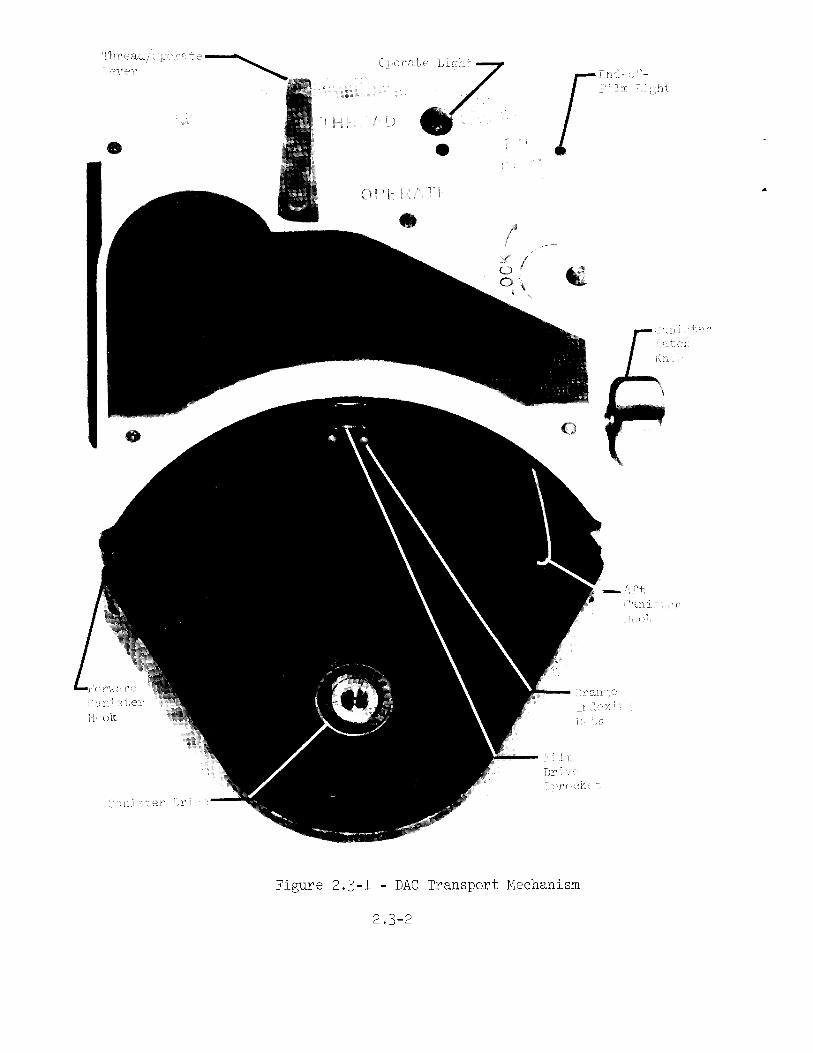
DAC Transport Mechanism (SEB33lOO278>:
The DAC Transport Mechanism installs on the DAC like a film
magazine and provides the threading and positioning for the
film from the DAC Film Cassettes (see 2.M). The DAC Trans-
port Mechanism is driven by and receives its framingsynchronization from the DAC itself.
Significant Configurations:
Configuration Purpose
-301 Skylab flight unit
Characteristics:
' Manufactured by J. A. Maurer, Inc., Long Island City,New York lllCl.
-
weight - 2.0 its (903 s- ).Envelope - 2.0 X 8.2 X 5.M in (5.1 X 20.3 X l3.7 cm).Volume - 86.U ing (lUl6 cm3>.
- Interfaces with DAC in the same way as the DAC Film
Magazine (lHO> (see 2.2) providing film plane location,electrical interconnection, and slot for magazineattachment latch of DAC.
`
Provides for attachment of two DAC Film Cassettes (Moo)(see 2.H) - one for film supply (toward camera) and
one for film take-up. Attachment latches for supplycassette are marked with "S" and for take-up with "TU".
° A two position lever is provided for the selection of
"THREAD" and "OPERATE" functions. An amber lightilluminates when in the THREAD position.
- The red light at the rear of the mechanism illuminates
when no film remains. The light remains energized and
the DAC continues to run when the film supply is depleted
- This transport mechanism has been qualification tested
for use in the Skylab vehicles and during EVA operations.
2.3-l
s-»mf; Q;/Vim
_M
A:
þÿ�C�} ��f�:�r�'�&�z ��@�L�E�,�;�;�?�e�'�iLE,;;?e'ilf; Y; xl
`$ =£>`=
`
yy,
,___M TH ] YI þÿ � "Wi
q
r §§§@i 5þÿ �� �,&
D ; 0
þÿ �
þÿ ��l�)�§�P�§�rþÿ�§�i�§ ��`�\? §
þÿ � 56f
.
/
C5 \s
r
\
$ %» An£3 þÿ �
5,M
§
4
=
1 »f ==Z;h_».@§s;=5~, W.) yi
,_
wr. w=~ r;` E"WI `
lr þÿ�1�"�'�w ��:�mic
þÿ�1�;�1�1�_ ¬�1�þ̀ÿ ��Q þÿ �� , ,`,_,3,
iv x
M,
V . rm; if
if;" ` *EFF=` ,
Sw \`\ Q*§ .
'F
\ i`
f \
=
`
>F þÿ ��f1
s W\ W
Ar A,
þÿ�¢�I�f ��,�_�\�/�M þÿ�¢�I�f ��,�_�\�/ M
~\4,_;~»Q~.1 1) 1
2
s1>,;~»\,\,l ,~ þÿ ��~ _
þÿ�" ��'�!�W�,�_�=
»
,
,
þÿ ��M~'-». .-...,~:,.»¢~ >
Figure 2.3-1 - DAC Transport Mechanism
2.3-2

2.M
2.H.1
2.U.2
DAC Fiim cassette (Moo) (SEB33100279):
The DAC Film Cassette is the film container for the DAC
Transport Mechanism (see 2.3). Two cassettes are required
for transport operation - one for film supply and one for
take-up. The cassettes are interchangeable and provide the
largest film capacity for the DAC system - Moo feet of thin
base 16 mm. film.
Significant Configurations:
Configuration Purpose
-301 Skylab flight unit
Characteristics:
' Manufactured by J. A. Maurer, Inc., Long Island City,New York 11101.
'
weight with film - 1.2 its ( 5A5 g.)Weight without film - 0.7 lbs (318 g.).Envelope - 5.88 dia X 0.88 in (15.0 dia X 2.1 cm).Volume - 2H.0 in3 (392 @m3).
' Fihn capacity of Moo feet (122 meters) of thin base film
(2.5 mil, 6A um) provides maximum run durations of
267 min at l fps, 13M min at 2 fps, MM min at 6 fps,22 min at 12 fps, and ll min at 2M fps.
° Cassette film must be loaded and unloaded in a photo-
graphic darkroom.
'
Attach to the DAC Transport Mechanism (see 2.3) for use
as film supply and as film take-up.
þÿ � Film usage indicator has markings at every 10 percent of
capacity showing the gross amount of film remaining.
The DAC Film Cassette has been qualification tested for
use in the Skylab vehicles and during EVA operations.
2.H-1

+3+3ii)no
LQ
03Q;
Nw/
ifQU
4-3UL?
wi
Sr» ,___
, ~
=§= _ _ _
..»,
~
,
þÿ ��_ é,______
il _ 5__
= lg;f;»¢f=_1_§;il' @_ ~"' '~
_
_ _ > =~`
we =_ ,= =¢~=1§~~~ __ *E* w 1- ; I
Q() þÿ �
_ '_>f;~gf§;þ̀ÿ ��~�%�f�=�§�f�f�~�i�f�;�;�¢�;�;�i�§�§�§�~ ��§�3�3�§�§ 1 1 `f;;~_;; ,_
?~="®$_§~;,~fþÿ�f ��'�f�`�y�:�_�=�¢�.�¢þÿ�L�f �72þÿ�s ��Q�é�§�&�§�;þÿ �~ £6 þÿ ��f�i�s�x�s3f§"~f1;~6 þÿ ��:�¢
`
þÿ ��_ ¬�\ ¬ � f_ N sw J þÿ�@�:�$�»�_�&�w ¬�§�§�~�~_»,§§,§_,~_»_§¢§¢; > ~ _qi
þÿ ��®�@�*�»�@�w�@�@�§�§�4�°Af@%&%¢meww ¥w%~_ :_f_f:~~f 5:4,:*W=;,a~f:gg¥ff;,§ þÿ�~�~�_�¢�.�»�_�§�v�~�~�f�X�¢�s ��f�f�~�f�¢�¢�»�~�;�_�#�_�;�~�=�»�_�~�¢ ��~�=�~ _~;fm¢"~i 3 O
+5
§%§§§%§§@@#%¥aqm §§%§§;w£ wee;,_g, ik `
þÿ�,�l�Q�`�~�_�`�_ ¬.i?§Pff SM
``
\ ~ `,$~§A;__1"$?1§¥;?*:5;,§§i5\ _iiiftg U i%T5~== _ QQew@§§@@@@e®@% ~H w@w$¥&me¢ *@§ *U
þÿ�` �
'N = r-4 <
@§%@e%@@@§%_* @§@e§ we
- =
~ »
f%@w@ww&@@§w& _@%%§ ée m 6
_ #SELL »-'
§§§m_ ~§§®§ $&§§` §I 5
~_ -_ :;==»s=þÿ ��>�a�=�'�_�=�&�;�=�f�s; »ss=,=>._ `;;,g -5;~ -35,_ ,g -5;~
-35 ,_
_. `
__ =§E¥=:>"2 `- :__ þÿ �
§§$@ 'ie #@§$þÿ� �I�i�:�k�w�=�* ��~�E�I�2�=�~�=�E�E�*�`�E�=�i ��=�` = ;
-»
_ 5
~
,gm 3 _
e° ~ þÿ ��g�e if ;; ~`==__ _> 1 ~
________
§§w_ %§i _
"
~"" þÿ �
E =;T-5 __
§§£ ;%@§5 »*
§§u §@%§
f - _=~ _: @ `1" -
@§@§ m§ %%
þÿ �
§@@&%%< éee ee
N@$@%w wwf fe
~%@%§@@@% »¢w%'
§
'I =
=
'
®,§iEf~
'
;m;§f f _~ _~ _f¢=@f;~#s,~~m5~@§_»>~_=22' »_@_%@=» _&;_ffQ,_ þÿ�=�.�»�-� �_�5�_� �=�= ��_�_�-�=_-»-==_=== _
eaeeeeggeeeefg@@§e§§§§§§§¢e§§ §= "».
: ~_ ~ ,< -
þÿ ��
þÿ�`�* ��é�%�i�§�¥�¢�@�§�»�§�e�:�§�@�&�§�§�%�e� �§�%�§�§�@�&�§�%�e�¥�a Saþÿ �
_ *'
__ 1511_ s aj?
þÿ ��s_j1~__
~ .
f
Figure 2.M-1 - DAC Film Cassette (hoo)2.LL-2
ilG)
213'Pi
þÿ�r ��i
E3
Ma
Q.£@
Me
¢mO
'ri
w
_CEþÿ�L�°�° ��1

5
5
5
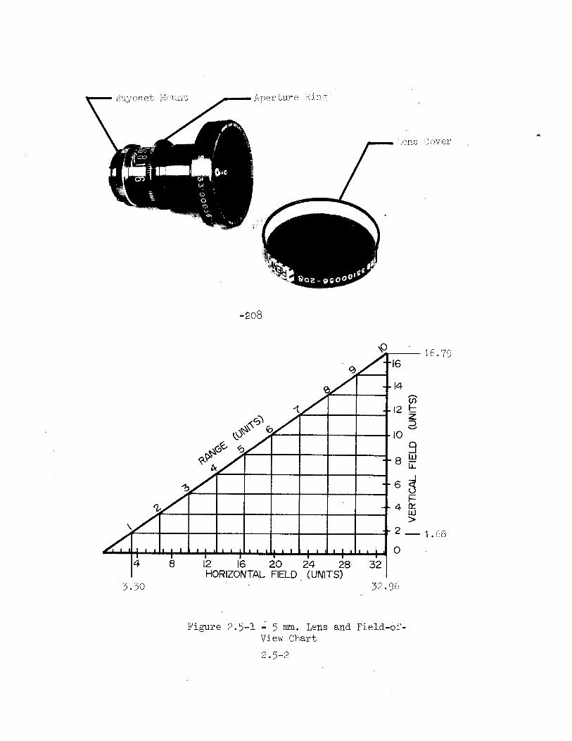
5 mm. Lens (SEB33lOOO56):
This is the widest field-of-view lens available for the DAC
system. It is used primarily for interior photography when
maximum area coverage is desired and where detail and geo-
metrical fidelity are less important. Even though the barrel
distortion effects of this lens are minimal for a lens of
such short focal length, the effects are noticeable.
Significant Configurations:
Configuration Purpose
-208 Apollo and Skylab flight unit
Characteristics:
' Manufactured by Fairchild Space and Defense Systems, Inc.
El Segundo, California 902M5.
' weight with Cover _ o.69 ibs. (313 g.).Envelope (less tab) - 2.lM dia. X 3.02 in. (5.3M dia X 7voiume - lO.l 1n.3 (l78.0 ¢m.3).
°
Field-of-view~ - ll7.5O X 8o.2°; 1600 diagonai.
Focus is fixed and good from the front of the lens to
infinity.
'
Aperture - f/2.0 to f/l6 with detents at each full-stopvalue. A sturdy tab is provided to assist in aperturering setting and in lens installation and removal.
- Lens cover is part of lens assembly and protects front
glass surface.
°
This lens has been qualification tested for use in the
Skylab and Apollo vehicles and during EVA operations.
2.5-l
3
.67 cm
§fie.yc>net §»1<i;»Lm't Aperture King;
f§»~»»a»,&3 3
_ _ g I,,
~
°»fT-§`5 _f
...a <
(
1 mm TTTT We2 þÿ ��c�n uf
`
, § Qþÿ �
þÿ � OO
tn1
þÿ �� on 5,
Q 4* '_ tgfi
x 902 _ SQUOG
-208A
A__
A-I:-I
1-jing------I
A-I-Ilju.Allllllml O
4 8 I2 I6 2O 24 28 32
HORIZONTAL F|ELD_ (UNITS)5.30
' 32-95
Figure 2.5-1 -l 5 mm. Lens and Field-Of?View Chart
2 . 5-2
m ,,
16.79
1.68

2.6
2.6.1
2.6.2
10 mm. Lens (SEB331000l0):
The 10 mm. Lens has a wide field-of-view, a large relative
aperture, and very good resolution and distortion character-
istics. The lens is most useful for interior vehicle
photography where illumination is low and where moderate
engineering detail is to be recorded. The low distortion
property of this lens has made it well suited for recording
EVA and lunar surface operations also.
S ignificant Configurations :
Configuration Purpose
_¢301 Skylab and Apollo CM flight unit
-302 Apollo LM flight unit; narrow teflon
lens shade
-303 Apollo lunar surface unit; no focus
tab and focus fixed at 6 feet with
tape
Characteristics:
þÿ � Manufactured by Kern and Co. AG, Aarau, Switzerland, and
distributed by Paillard, Inc., Linden, New Jersey 07036.
-
weight - 0.60 ibs. (272 g.).Envelope (less tabs) - 1.97 dia. X 2.03 in. (5.0 dia X
5.16 cm.)Volume - 6.18 in.3 (101.3 cm.3)
°
Field-of-view - 5H.9O X M1.l0; 65.20 diagonal.
' Focus range- 8 inches to infinity with detents and markings
for 2 feet and infinity and with only markings for 8, 9,and 10 inches and for 1, 1.5, 3, and 6 feet. The 2 foot
setting provides sharp focus to infinity for aperture
settings for T/5.6 through T/22. At the closest focus
setting, the subject should be M.7 inches (11.9 cm.)from the lens front edge.
° Aperture - T/1.8 through T/22 with detents at each full
5
stop value.
þÿ �
Sturdy tabs are provided on the aperture and focus rings» to assist in setting and in lens installation and removal.
2.6-1

'
This lens has been qualification tested for use in theSkylab and Apollo vehicles, on the lunar surface, and
during EVA operations.
ocus Ring T Sto in
.530
/ff þÿ ��f�s a
5° itQ
.
~
Q I
0 þÿ ��Q þÿ ��f�i_»_i
45 I
þÿ �� �7�`�»�i�§�"�`V þÿ �
I
g, 1'
& / /
þÿ� �=� �"�" �_ 1-,
_g g
-301 O2 Irefifi
'7.50
q 7
%6 23
1 __ t
WN --I 5 5QQ 6
<&>&6þÿ ��J� 4 E
Q
Al---I if&3 3
», __---- Q2 P
fi ____-_I aI----_-_I
>
0.75
Il______i OI 4 6 7 3 9 IO
HOWZONTAL HELD (UMTS)
1.04 1o.39
Figure 2.6-l - l0 mm. Lens and Field-of-View Chart
2.6-2

2.7
2.7.1
2.7.2
18 mm. Lens §SEB33100018):
The 18 mm. Lens has the largest relative aperture of the DAC
system and is the widest field-of-view lens that can be used
with the Right Angle Mirror (see 2.12). The lens is especiallyuseful for vehicle-to-vehicle docking and detailed interior
Apollo and Skylab flight unit; standard
photography.
Significant Configurations:
Configuration Purpose
-301mirror interface
-302 Skylab Exp. T020
interface and no
-303 Skylab Exp. MM79interface and no
Characteristics
unit; no mirror
control tabs
unit; rotated mirror
control tabs
Manufactured by Kern and Co. AG, Aarau, Switzerland, and
distributed by Paillard, Inc., Linden, New Jersey 07036.
'
Weight - o.8o lbs. (36M g.).Envelope (less tabs) - 2.1M dia X 2.60 in. (5.H3 dia X
6.60 cm.).Volume - 9.36 in.3 (153 cm.3).
' Field-of-view - 32.60 X 23.HO; 39.20 diagonal.
' Focus range - 1 foot to infinity with detents and markingsfor 10 feet and infinity and with only markings for 1,1.5, 2, 3, and 5 feet. The 10 foot setting providessharp focus to infinity for aperture settings of T/Hthrough T/22. At the closest focus setting, the subjectshould be 8.9 inches (22.6 cm.) from the lens front edge.
~ Aperture - T/1.0 through T/22 with detehte at each full
stop value.
~ Sturdy tabs are provided on the aperture and focus ringsto assist in setting and in lens installation and removal.
(Except -302 and -303 configurations, see 2.7.1.)
'
Accepts attachment of the Right Angle Mirror (see 2.7.1and 2.12).
2.7-1

Skylab and Apollo vehicles and during EVA operations
Focus Ring T Stop Ring
. ».::_
_I
»
,
` þÿ�=�`�~�1 � PI;l,.. »,
gs
, .ZVT §§_<.1=,==_$
\_If
_
II*
é I;
¢»
_
/\)` w =:,
X
þÿ �
\~-
,,.,_
'
~~, inkr, `§
`,
þÿ �
This lens has been qualification tested for use in the
qu§
þÿ�@�` � ¥ ¢ <þÿ �
I
? ,rxif þÿ�" ��; ��1�>�§�5 45S
xp þÿ ��Q »»\
uw
J?
Mirror Adaptor
-301
O'
-302
Q
4
3
®"%\t--I V
N _--I2 _--I2
~ --Il-_--Il-
I, ------_ \ -------- 0.42
_-_-_I___0
I 2 3 4 5
0-58 HORIZONTAL FIELD (UNITS) 5-80
Figure 2.7-l - 18 mm. Lens and Field-of-View Chart
2.7-2
4.16
I-4

2.8
2.8.1
2.8.2
25 mm. Lens (SEB33l0005H):
This focal length lens is the standard for l6 mm. photography
providing the "normal" visual scene coverage. The large
relative aperture of this lens is especially useful for dimly
lighted photographic situations.
Significant Configurations:
Configuration Purpose
-202 Basic flight unit; incroporated in
Skylab Experiment T027 assembly.
Characteristics:
Manufactured by P. Angenieux, Paris, France.
'
weight - 0.30 lbs. (136 g.).Envelope - 1.6M dia X 2.ll in. (H.l7 dia X 5.30 cm.).Volume - M.H6 in.3 (73.0 cm.3).
- Field-of-view - 23.50 X l7.lO; 28.70 diagonal.
þÿ �
Focus range- l8 inches to infinity with no detents
provided. Focus is marked for lo, 2l, 2M, 27, 30, 36,and M2 inches and for M, 5, 7, l0, l5, and 30 feet and
for infinity.
- Aperture - f/0.95 (T/l.05) through f/22 with detents at
each full stop value.
- This lens has been qualification tested for use in the
Gemini and the Skylab vehicles.
2.8-l

Aperture R1ng _fþÿ�I �
Index
A-<°° A--_
Ie Al--II ____l
I _-___ þÿ �
|i=I====EQHKQHHHHHI
0.42 HORIZONTAL FIELD (UNIT) 4.16
Figure 2.8-1 - 25 mm. Lens and Fleld-of
View Chart
2 8-2
Focus R1ng
MountingIndex
t Mount
W
30

2.9 75 mm. Lens (SEB33l000l9>:
This moderate telephoto lens is used primarily for photo-
graphing distant objects. With the focal length and narrow
field-of-View of this lens, bracket mounting and precise
aiming are recommended.
2.9.l Significant Configurations:
Configuration Purpose
-302 Apollo and Skylab CM unit; standard
usage
-303 Skylab Exp. M551-5 unit; extender
for close focus incorporated and no
control tabs
2.9.2 Characteristics:
°
Manufactured by Kern and Co. AG, Aarau, Switzerland, and
distributed by Paillard, lnc., Linden, New Jersey 07036.
'
Weight (-302) - 0.85 lbs. (386 g.).(-303) - 0.90 ibs. (MO9g.).
Envelope (less tabs) (-302) - 2.lM dia X 3.53 in.
(5.3M dia X 8.96 cm.).(-303) - 2.lH dia X M.u7 in.
(5.3M dia X ll.35 cm.).voiume (-302) - l2.7 1n.3 (208 ¢m.3).
(-303) - 16.1 in.3 (26M cm.3).
° Field-of-View (-302) - 8.00 X 5.605 l0.0O diagonal.(-303) - 6.00 X M.H0; 7.MO diagonal.
' Focus range (-302) - 5 feet to infinity with detents and
markings for l0 feet and infinity and with only markingsfor 5, 5.5, 6, 6.5, 7, 8, 9, l2, l5, 20, 30, 50, and
l00 feet. The 10 foot setting provides sharp focus from
8.9 to ll.M feet for T/8 and from 8.5 to l2.l feet for
T/ll.(-303) - l3.M to lH.9 inches from the film
plane with detents at the lH.M and the lM.9 inch ranges.
The focus scale markings are unchanged from the -302
configuration; the incorporated eXtender of the -303
configuration produces the close-up focusing characteristics
2.9-l

~ þÿ ��f �S UE Finþÿ�c�@�u ��_�H�;�_�5
I
'IN f
(Dll
Q b _Ilþÿ�§ ��°
llill_-___-
P. I_l-_I--I--l_ll
KIHHIHBIH0.2 0.4 0.6 0.8 1.0 1.2
0.
1' _ <`,'.hfti
>~ > -DJ1 i i
Il W ~¢w;
é"§ `
S' 45'`
~~ ' f þÿ�d�i �m
`/
, þÿ�I �
¢§§f fa 1 (5W5
J§ i :gg i, f'
Q0.99
Q.
%f
0.8
W -
,
V
þÿ�\ � 0.6Qf P4
%~
þÿ � 0.4 H
"5
O_]4HORIZONTAL FIELD (UNITS) 1_38
Figure 2.9-1 - 75 mm.-Lens (-302) and Field-of-View Chart
2.9-2

'
Aperture (-302) - T/2.H through T/22 with detents at each
full stop and at the T/2.H setting.
(-303) - marked the same as the -302 configura-
tion; however, the relative aperture is reduced by 0.6
stop because of the lens extension. The marked aperture
values are actually the aperture values as follows: T/2is T/3.1, T/2.8 is T/3.6, T/A is T/5.2, T/5.6 is T/7.3,T/8 is T/io.M, T/ii is T/lH.3, T/16 is T/20.8, and T/22is T/28.6.
Sturdy tabs are provided (-302 only) on the aperture and
focus rings to assist in setting and in lens installa-
tion and removal.
°
Accept attachment of the Right Angle Mirror (see 2.12).
This lens has been qualification tested for use in the
Skylab and Apollo vehicles and during EVA operations.
Extender
,f . 3°",_
g `§7#}rþÿ ��F
=
p
,_
\.,»q.
__ W
_ fm? .~ r
.s s we y þÿ�f�f �'sis
f
vs. * Q,
~`~».=>
//I 9 MnQ s\ J. ,.=' ,
`
& 8 $-- s ,_q sg 8
R d
þÿ ��Q;;i;;_,` f f
"», ss .
þÿ �
f_
,:,
- si g - _,Eg ,
V g 6þÿ�J �Nj
W sþÿ ��a�f�f 7
s f f
s þÿ�f�s �þÿ�'�¢ ��s�'�f¢ f'
5
Figure 2.9-2 - 75 mm. Lens (-3OM) With Incorporated Extender For
Close Focus
2-9-3
.M


The l00 mm. Lens is intended for distant object photography.With an extender tube incorporated on the rear of the lens,close range photography is made possible. The long focal
length and narrow field-of-view of this lens necessitate
bracket mounting and precise aiming.ThiS iS & COmm@TCi&l l@HS
Purpose
Standard usage unit
Skylab Exp. M551-5 unit; extender
for close focus incorporated
2.l0 100 mm. Lens (SEB33l00025):
and will not be utilized after Sky ab.
2.l0.l Significant Configurations:
Configuration
-202
-203
2.10.2 Characteristics:
' Manufactured by Schneider 0ptische Werke, Kreuznach, W.
Germany, and distributed by Burleigh Brooks, Inc.,Englewood, New Jersey 07631.
- w@gnu(-mQ)- Ll2lb& Qm8g.L
Envelope (-202)<'203)
Volume (-202) -
(-203) -
° Field-of-view (_(_
(-203) - 1.22 lbs. (55M g.).M0- 2.1M dia X H. in. (5.3H dia X ll.l8 cm.
. in. (5.3M dia X lM.72 cm.
15.8 in.3 (259 @m.3).20.1 1n.3 (BHB
- 2.1M dis X 5 80
cm.3).
202) - 5.90 X h.30; 7.30 disgsnsi.203) - u.3° X 3.1O; 5.u° disgsnsi.
° Focus range (-202) - 5 feet to infinity with no detented
Settings, Focus is marked for 6, 6.5, 7, 7.5, 8, 8.5,9, 10, 11, 12, in, 16, 18, 20, 25, 30, Mo, 50, and 100
feet and for infinity.(-203) - 20.0 to 2l.7 inches from the film
plane. The focus scale markings are unchanged from the
-202 configuration; the incorporated extender of the
-203 configuration produces the close-up focusingCharacteristics, Focus is locked at proper distance for
eXperiments.°
Aperture (-202)(-203)
- f/2.8 through f/32 with no detents.- marked the same as the -202 configura-
tion; however, the relative aperture is reduced by 0.7stop because of the lens extension. The marked aperturevalues are actually the aperture values as follows: f/2.8is f/3.8, f/M is f/5.u, f/5.6 is f/7.6, f/8 is f/l0.8,f/11 is f/15, f/16 is f/21, f/22 is f/30, and f/32 is f/M3.
2.10-l

741 R -
I CDCUS .fill
J;§;~_1,_
.4 _,
_
~ þÿ�%�* ��¢�_,
_ z>»¢1§
_MZ `
, ==.
_
_
V, __,_
Q_ _
I
_
`_ _I
_ t
Ias
3 Q'
iw n
~§ ____ K
,_
Qi
i
1_
-~
MX "
þÿ�" � ��~�.�S
T Stop Ring
1°0.76
9
0.78 _
U2
_Q 7 ll þÿ�®�" � 6 -_ if
þÿ�@�"�Q ��@5 _--_ 3o.L+ .3
R
i ----- H
--__ (33 E
2 þÿ�-�-�-�-�- � O-2 2
--- 0þÿ� �-�-�-�-�-�-�- �
M8
þÿ ��_@_]_QLi 0.2 0.)-¥ 0.6 0.8 1.0
0.10_3 0.5 0.7 0-9 1.0M
Horizontal Field (Units)
Figure 2.10-1 - 100 mm. Lens (-202) and Field-of-View Chart
2.10-2 þÿ�R ¬�V�.�A
9/5/72

- Accepts attachment of the Right Angle Mirror (see 2.12).
' This lens has been qualification tested for use in the
Skylab and Apollo vehicles
ExtenderfiTTCT Ad3§f
þÿ�Q ��-
A
,_
` ni» þÿ � � ��1~-`=
ti, þÿ �
Q;z
1,~* "w .A
þÿ�' ��%�u�;�' _
I þÿ ��>�r '~~ ' H
r -_ p
'
== __ / _
~w@¢¢» ~ l@@¢A » = J
þÿ ��1�%�%�v�¢�» larvae# . ;i'
, ;;~c;§';¢f;¢Q`
. I
&l@f%%%§§§§§@§§%»}~,7þÿ�s�@�~�M�" ��%�f�w�%�&�i£¥ þÿ�! ��»
þÿ�' ��@�@�§�§�a�`�%�§U
Figure 2.10-2 - lOO mm. Lens (-203) with Incorporated Extender for
Close Focus
2.10-3


2.11
2.11.1
2.11.2
180 mm. Lens (SEB331000l7>:
The 180 mm. Lens is the longest focal length lens available
in the DAC system. Its primary use is for distant object
photography. The very long focal length and narrow fie1d-of-
view of this lens necessitate bracket mounting and preciseaiming.
Significant Configurations:
Configuration Purpose
-301 Basic flight unit - not currently in
use
Characteristics:
°
Manufactured by Kern and Co. AG, Aarau, Switzerland, and
distributed by Paillard, Inc., Linden, New Jersey 07036.
'
Weight - 1.36 lbs. (618 g.).Envelope (less tabs) - 2.1M dia X 6.53 in (5.3M dia X 16.60Volume - 23.5 in.3 (385 @m.3).
- Field-of-view - 3.30 X 2.M©; u.i Odiagonal.
þÿ � Focus range - 15 feet to infinity with no detented settingsFocus is marked for 15, 16, 18, 20, 25, 30, 35, MO, 50, 70,100, and 200 feet and for infinity.
» Aperture - T/H.6 to %/32 with a detent at each full stopand at the T/M.6 setting.
- Sturdy tabs are provided on the aperture and focus ringsto assist in setting and in lens installation and removal.
° Accepts attachement of the Right Angle Mirror (see 2.12).
- This lens has been qualification tested for use in the
Skylab and Apollo vehicles and during EVA operations.
2.11-l

~ Aperture Ring
Aperture Index Focus Index
Mirror Mounting Adapter
,f
.H,
`
of:g
,
__M.___
M
M
w þÿ ��` ��.�,_u.N 1.
£§§$
-~1~~f r_ tru þÿ�t�t� � ,
,_
4
Cla
ii#
10
~ 9
þÿ�Q�@�,�¢�é �\
6
5 ___-M --__-_--___
_--___-________
0 03
Horlzontal Fleld (UnltS)
Focus Ring
Bayonet Mount
e `-tw*
§s:j= _- ~
0.21
3
0.052
10.02
0.1'
0.2' 0.29
Figure 2.11-1 - 180 mm. Lens and Field-of-View Chart
2.11-2

2.12
2.12.1
2.12.2
Right Angle Mirror (SEB33l0005l):
The Right Angle Mirror assembly bayonet mounts onto the front
of several of the DAC lenses for photographic coverage at a
right angle to the lens optical axis.
Significant Configuration:
Configuration Purpose
-205 Apollo and Skylab flight unit
Characteristics:
° Manufactured by Technical Services Division, NASA MSC,
Houston, Texas 77058.
-
weight - 0.16 lbs. (72.6 g.).Envelope - 2.1M d§aX 2.2 in. (5.3P+dia X 5.59 cm.).Volume - 7.92 in. (130 cm.3).
°
Mirror is a front surface polished glass plate, silvered
for maximum optical reflectance and protected by an
aluminum with silicone monoxide coating.
°
Bayonet mounting is indexed and installs on the lens in
only one orientation. Can be installed on the l8 mm.
Lens (see 2.7), 75 mm- Lens (see 2.9), l00 mm. Lens
(see 2.l0), and 180 mm. Lens (see 2.11).
'
The Right Angle Mirror has been qualified for use in the
Skylab and Apollo vehicles.
¢~i12~ f~ .~~~ ~ -~
~ , _
ii? édus
2 if @$§§¥ §i§~
f ssmss ..Z ,isfiy1 "+»~ ~ ~
f §%§m@ iwmsss MOUHtlU% IHCQX
f ~
_
þÿ � þÿ �
liiiliiiffli
_._,r~~~}H¢ 2 .§§@§% ¥@%§§s
1 @§§§%% §§§¥?g þÿ�-�Q � � 1
Figure 2.12-l - Right Angle Mirror
2.12-l


2.13 DAC Power Cable QCM)(SEB33lOOO38):
This cable is used in the CM to provide spacecraft power to
the DAC.
2.13.1 Significant Configurations:
Configuration Purpose
-301 CM flight unit for Apollo and Skylabmissions
2.13.2 Characteristics:
'
Manufactured by Technical Services Division, NASA MBC,Houston, Texas 77058.
-
weight - 0.23 lbs (lOl+.3 g.).Length - 108 i L+ in. (9 i 0.3 ft.) (27l+ i io ¢m.).
'
Connects DAC to CM Panels 15, 16, and lOO.
°
This three wire cable includes a Bendix type JTO6P-8-63
bayonet connector on the DAC end and a Deutsch type 127-
3-9P push-pull connector on the CM end.
This cable has been qualified for use in the Skylab and
Apollo vehicles.
k.
þÿ ��» era tonnector _ anannang; tnt Q wacecraft Connector~- _ w§R>@.=a§§>=§~>~ _- .wgfa 2 ~
~~ ._ _ __
__
þÿ �
_ __.,___.,_
Z, ~.__
`
`
1 A ~.~»»
~as Z »
i
' : '
;~ "s. \ -:' 'E
-1-
`
,_A
i
þÿ ��~ þÿ � ��' J
'
_f~gn
...... nni if '
~
ffþÿ � f
2 gens.s
net >
*~*a@§§e2 þÿ ��%�w�` ag_. Qwwm
ln
= þÿ �
ein? .¢¥ ¢@§ §§
_
i_>a__ = siesi,¢nn ne g? ..,., == _-~==-_ -s.. ~ __ ,_ n M,,_m,;_ Q L_.,
_ _ _ __ .... , __ __ _,.. __ __ _ _s__»\ Q __ __ N. A ,_ ~;e.,__
_ §§~ `\ ~
_ þÿ ��@�%�£�m�@ ��'�_ »@§sn\.;_
'P þÿ�-�»�- � � ��7 þÿ ��
\_. ,._:_ _» if - _
_- sr
5,NCHES ®@@@w§%§§$%§é
aw? `f`~*Ei iff;
Z f þÿ �
_ _ _ __
þÿ�3�:�3�2�1�2�5� �§�1�¥�f�¥ ��§�I�¥�§�%�§�@�f�¥�§ ��q�§�\�¥�f�1�_�§�§�§�f�fþÿ�;�;�~�;�f�5�;�;�'�;�_�z�é�§�2�,�~�§�?�;�.�~�~�_�f�_�¥�~�§�T�§�;�§�1�g�1�u�_ ��§�_�§�~�_�i; gj; ;~=w;~;_; ~_=_.X~¢_~=w;~;_; ~_= _ .X~¢ _
, =~_>: _E := _ _
__ _
,_ _
_
_ __ _
,__ _
_
Figure 2.13-l - DAC Power Cable (CM)
2.13-1


2.lH
2.lH.l
2.lH.2
Spacecraft "C-g"Connector
DAC Power Cable gsws) (SEC33lOO567):
This cable is used in the Skylab OWS and M A to provide
power to the DAC.
Significant Configurations:
Configuration Purpose
-303 Skylab flight unit
Characteristics:
Manufactured by Technical Services Division, NASA MSC,
Houston, Texas 77058.
° Weight - l.O lb . (M5Hg.).Length - l8O i é in. (15 i §'gft-5 (H57 i 13cm.).
- Connects the DAC to the OWS utility outlets.
' This three wire shielded cable includes a Bendix type
JTO6P-8-6S bayonet connector on the DAC end and a Bendix
type ZG6El5ll-98-PA zero g connector on the SWS end.
° This cable has been qualified for use in the Skylab
vehicles.
Camera Connector
\`
§ .
f
§x .l~~
fyf f .
`~`_,_
°?ixii .SSS
"D
§ 1 yctdtþÿ�t ��§ ��` �
'~.;_ ,
H H
Figure 2.1M-l - DAC Power C&ble (SWS)
2.1M-l

2.15
2.15.1
2.15.2
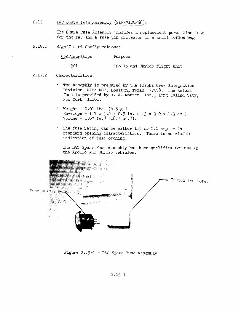
DAC Spare Fuse Assembly (SEB33l00266):
The Spare Fuse Assembly includes a replacement power line fuse
for the DAC and a fuse pin protector in a small teflon bag.
Significant Configurations:
Configuration Purpose
-301 Apollo and Skylab flight unit
Characteristics:
The assembly is prepared by the Flight Crew IntegrationDivision, NASA MSC, Houston, Texas 77058. The actual
fuse is provided by J. A. Maurer, Inc., Long Island City,New York lllOl.
'
weight - 0.01 lbs. (L+.5 g.).Envelope - 1.7 X l.2 X 0.5 in. (U.3 X 3.0 X l.3 cm.).voiume - 1.02 111.3 (16.7 ¢m.3).
The fuse rating can be either l.5 or 2.0 amp. with
standard opening characteristics. There is no visibleindication of fuse opening.
The DAC Spare Fuse Assembly has been qualified for use inthe Apollo and Skylab vehicles.
.;==»`~E2S;§%»E;; $¥.$z:>¢~¥,'=þÿ�§�x�>�3�_�; ��:s -1, _
þÿ� �i�~ ��,�_�;�.�»�.�:�» ~
_ e»,».,....,.. .
:_ I- #_ Qi þÿ ��°�-"is sw# fig. *
-1_;.;,~.s=;=.,sa-=§»; .»::_.¢f¢.ff» ; .»::_.¢f¢.ff::_.¢f¢. ff
;s§ssi§isf1i§;;§;;i§;;<sfeiicis ;?~* . 1 E f
@&§&§§%§,,_g§l%wW, §ETODGCDLVGCover
~
=._==. 1. K _,
. LAN .QN 1
þÿ ��\�a�§*"";;».Q
~. .
\\ \ X ,»
\ gg( .,_Q ..
\\`\=Q5% Q 5%, _.._ Iþÿ� �;�¥�_�3�»�§�i�,�,�, �
A
þÿ�\ �§;\ þÿ ��< 5% xg? X
\ if »> 1 Q
A
mg wi fa @
\ #xxx R*
1
, ,ig _1.~~_5 ,_ ,_ __ 4 A
§f
,M _,_,,
Fuse Holder _ þÿ�g�*�1�T �_. _
I
`
_ fp; _
`
_,Y ,»-ee.__
1;¢ A
1. þÿ�m�n�m�U�!�l�l�!�*�'�§ �
.
.~~_
" `
A
Figure 2.15-l - DAC Spare Fuse Assembly
2.15-l


2.16
2.16.1
2.16.2
Remote centrei Cable (SEB33lOOO2O):
This cable provides for remote operation of the DAC and
Hasselblad cameras.
Significant Configurations:
Configuration Purpose
-301 Apollo CM; indicator light in cable
button
-302 Apollo LM; indicator light in cable
button
-303 Apollo; without indicator light
-305 Skylab flight unit
Characteristics:
' Manufactured by J. A. Mau
New York lllOl.
' Configuration Weight
-301 l.O lbs.
-302 1.h ibe.
-303 0.7 lbs.
-305 l.3 lbs.
rer,
0151+
(636
(318
(591
Inc., Long Island City,
Length
g.) l2Oi2 in.
g.) l68i2 in.
g.) M8 i2 in.
g.) 2MOi%in.
(3OMi5 em.)
(u26i5 em.)
(122i5 em.)
(6O9i%5cm.
þÿ �
Cable incorporates a Deutsch type URA6-8-TP bayonet con-
nector for attachment to the DAC or the Hasselblad camera
accessory connector.
'
For DAC control, the camera operation can be started and
stopped and the camera sequencing modes can be selected
as follows:
Configuration Sequencing Modes
-301 l, 6, l2, and EM fps
-302 1, 6, 12, and 2M fps
-303 Time, 1, 6, 12, and EU fps
-305 Time, 2, 6, l2, and QM fps
Remote mode selection is independent of camera mode
selector switch setting. The camera operating mode is
2.16-l

determined by which operate button is used to start the
sequencing. DAC automatic operation can be stopped bydepressing and releasing either operate button.
For Hasselblad camera control, only camera actuation can
be triggered with the cable button. Remote mode selectorsetting has no effect in this case.
The cable configurations -301 and ~302 incorporate an
indicator lamp under the operate button. This lampflashes at the selected sequencing rate. The lamp opera-tion capability requires some wiring modifications in theDAC itself and eliminates the TIME mode.
The Remote Control Cables are qualified for use in theApollo and Skylab vehicles.
ACtuat@ Swifgh Frame Rate Selector
,,.MuW Camera Connector,3m®"",°` l
,
A
_.yi 4
'° '
~>~
sis. ,
H
Wm \
is
, þÿ�i�§�" � °~w la
0_
A g ._ ._ ,_
_`. ,
_ _ `
_
_ _.
_
3%iT@$*,..mr?,
.. mr?#A X N4 ,MW _.pq _ ,
x\`w§»M_Q\fT5Z£-~
Figure 2.16-l - Remote Control Cable (-305)
2.16-2

The power pack is a self-contained, nickel cadmium batterypower unit for the DAC system. lt is used primarily during
Purpose
Apollo lunar surface unit; one
mounting rail
Skylab flight unit; two mounting
2.17 DAC Power Pack (SEB33l0O3OH):
EVA photographic operations.
2.17.1 Significant Configurations:
Configuration
-303
-305rails
2.17.2 Characteristics:
° Manufactured by Technical Services Division, NASA MSC,Houston, Texas 77058.
- weight (-303) - h.2 lbs. (1908 g.).(305)-IA3 uw. @95ug )
Envelope (less cable)(-303) - 6.l X H.5 X 2.5 in.
(15.5 X ll.M X 6.M
(15.5 X ll.H X 6.9Volume (-303) - 68
(-305) - 78
' Power source is 2M
cm.).(-305) - 6
cm.)..6 in.3 (1122.1 16.3 (1213
rechargeable
1 X M.5 X 2.7 in.
cm.3).cm.3).
nickel cadmium batteries
type 1.2 SCL per Gould-National
Battery Division, St. Paul, Minnesota 55llM. The batteries
are potted and enclosed in a sealed stainless steel assemblyThe nominal open circuit voltage is 32.0 VDC with 1.1 amp.hours C&P&CitY~ The number of film magazines that can be
powered by a DAC Power Pack varies with DAC sequencing rateand length of time from Power Pack charging as follows:
DAC Magazine (lMO)
Batteries, Inc., Alkaline
DAC Cassette H00
15 QQ QQ Shelf Life (Days) 15 QQ _Q1 fps 1.5 1.2 1.1 0.5 0.u 0.32 fps 2.5 2 2 1.0 0.7 0.66 fps 7 6 5 2.0 2 1.712 fps 13 lO 9 u.7 A 3.52U fps 22 18 16 9 8 7
2.17-l

Rail
;_§~M `
fs _
Incorporated cable connects to DAC power connector (forward-most). Cable connector is a Bendix JTO6A-8-63 bayonet type.
The -303 pack connector incorporates a metal_tab assembly to
assist EVA gloved connection of cable to DAC. The total
cable/connector length is 7.5 i 0.5 in. (l9.05 i l.3 cm.).
The mounting rail of the -303 configuration attaches the
pack to the DAC Handle (see 2.20). One mounting rail of
the -305 configuration attaches to the DAC EVA Bracket
(see 2.l9) and the other to the Universal Mount (see 2.l8).
The Power Pack has been qualification tested for use in
the Apollo and Skylab vehicles and during EVA operations.
~gCamera Connector _»_»».1_1 I 1 lu;.~~_f þÿ ��~�_�,�»»
W ww :e,,~ mi is is ,,~.., ,,», , l, l , is
sf_ Q. 5.
~
ilI
i3'
T ccs;»< Qssgsaslsas
.
`
`~ i ii Ji gpg
1, .
_ _
' 'ffm h i s : > ff: lf 3; "<
fi_l*'s'_,_~5_v;_;, _x x 5
~
`:'§¥`i§.5¥<;;;,;§ ,~ >» ,
ii_;f=;_:1__g§§§ :i:. ip?_
§ _
,/~f//,C
if
Figure 2.17-l - DAC Power Pack (-305)
2 . 17-2
2,18
2.18.1
2.18.2
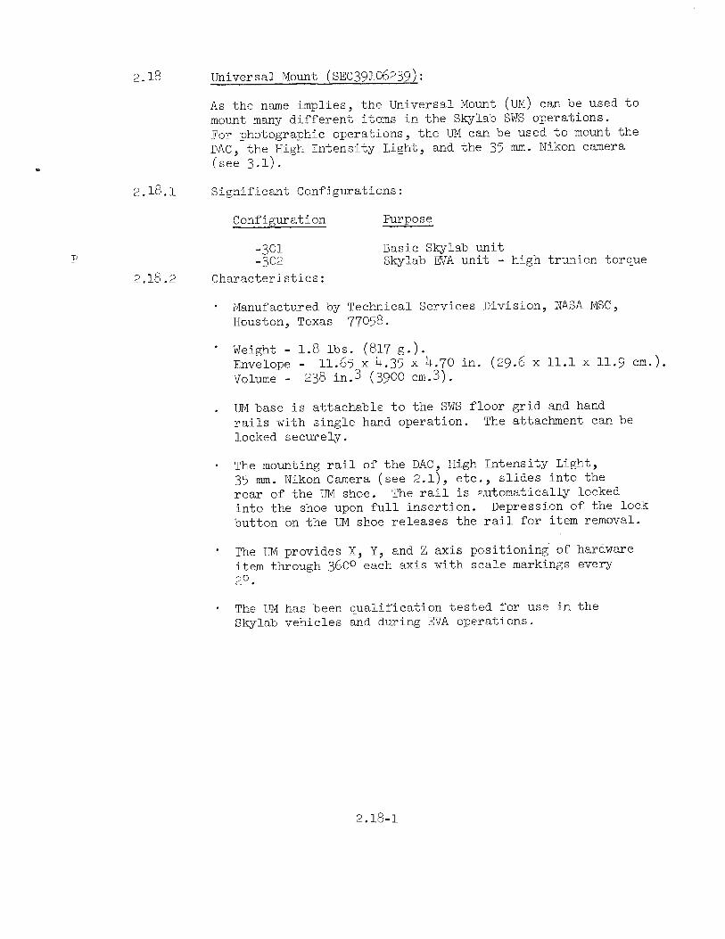
Universal Mount (sEc39io6239)=
As the name implies, the Universal Mount (UM) can be used to
mount many different items in the Skylab SWS operations.For photographic operations, the UM can be used to mount the
DAC,the>HighIntensity Light, and the 35 mm. Nikon camera
(see 3.1 .
Significant Configurations:
Configuration Purpose
-301 Basic Shylab unit
-302 Skylab EVA unit - high trunion torque
Characteristics:
' Manufactured by Technical Services Division, NASA MSC,
Houston, Texas 77058.
'
Weight - l.8 lbs. (817 g.).Envelope - ll.65 X u.35 X H.7O in. (29.6 X ll.l X ll.9 cm
Volume _ 238 in.3 (3900 ¢m.3).
. UM base is attachable to the SWS floor grid and hand
rails with single hand operation. The attachment can be
locked securely.
' The mounting rail of the DAC, High Intensity Light,35 mm. Nikon Camera (see 2.l), etc., slides into the
rear of the UM shoe. The rail is automatically locked
into the shoe upon full insertion. Depression of the lock
button on the UM shoe releases the rail for item removal.
'
The UM provides X, Y, and Z aXis positioning of hardware
item through 3600 each axis with scale markings every
20.
' The UM has been qualification tested for use in the
Skylab vehicles and during EVA operations.
2.18-l

Lock Lever
þÿ�:�f�l�'�l�@ ¬�XX Index Y
(I
r
~.§=»?.@
~=
þÿ�3 �Q
fs ,f°`;~f=z ; em; >f2»f@¢A»»:°f~= _
= þÿ �
~
1 ~_f;wW &,.Q», f
~~~f§§~;X»;; fi ek :~5__jf;,_535:15 =`=S.= Aff- '~\f;¢§¢1~¢»§~~!f2f§~ »=» -==¢==.~==. V < þÿ�>�f�X�K�>�f�X�~�f�@�`�~�§� �=�E� �.�"�?�.�'�:�?�:�'�5�:�:�. ��~�?�:�.�'�:�E�:�§�=�§�$�5�:fXK>fX~f@`~§ =E ."?.':?:þÿ�'�5�:�:�. ��~�?�:�.�'�:�E�:�§�=�§�$�5�:
,`§m_,,__L,_
§@§;l~g»`\g1~¢.~-ws-»-5-~.»~,=.¢»5¢`==>»`==¢~,=._ Q§ ¢
¢
; e 1;
"' %`§, K
`
me =,.\,
`
"0
, r rr
` i X
"
. --,= r M\
.> 3 SK
= S =
S§@,_1,_., ,r ,W
= §;§g§§,5;;§,:z\gi§;:¢:f;;:;g>g; :.fz_=j`:
þÿ� �»�@�»�@�»�;�,�@�;�=�»�1�~�f�i�;�§�5�§�5�;�1�m�i�;�; ¬�@�;�2�f�z�~�_�f�¢�f_
5.9§=S =w~=¢§§=~fs;§=¥§= , Ae :,, _ir ,
r
%§Img; gglniaihz ~ss=;§§¥§\as~ = Lff;-_,Q,Aw»A~,.:¢A=_¢,:.e..-,..\ as~ = Lff;-_,Q,Aw»A~,.:¢A=_¢,:.e..-, ..
r
§w
eg ey ;@>§§»;;»é@3;~§~>§~ ,
~
rm ; _
" i e, \§§`§§¥ i »
i f~ ~
, ,
þÿ � 5%
xwewz 2 %% am
þÿ ��e�e�e�m=
.
i,rw ..,,,
þÿ �
,_
Clamp Clamp Actuator
Figure 2.18-1 - Universal Mount
2.18-2
-Index Z
Camera Connector

2.19 DAC EVA Bracket (SEC33lOOOO6}:
This bracket provides the interconnection between the DAC
and the DAC Power Pack for Skylab EVA operations.
2.19.1 Significant Configurations:
Configuration Purpose
-301 Basic Skylab unit
2.19.2 Characteristics:
þÿ � Manufactured by J. A. Maurer, Inc., Long Island City,New York þÿ�l�l�l�O�l�. �
-
Weight - o.u lbs. (173 e.).Envelope - U.75 X 1.93 X 0.62 in. (12.1 X u.9 X 1.6 em.).Volume - 5.7 in.3 (93 cm.3).
- The mounting rails of the DAC and the DAC Power Pack
(see 2.17) slide into the rear of the EVA Bracket shoes.
Automatic locking is provided upon full insertion of rails
- The lock release lever on the bracket front is pressedtoward the unit to be unlocked and removed.
Camera Power Pack
Release Lever
.A%&§§§f wa . A
i. us .. X..
,
H%@§§§@w.ppsp
_,__
.L *www,
=`> an, ws ,
þÿ � þÿ �
_,_.f
0
_ 5 *Xs-
:_
§
%% _f »
Figure 2.19-l - DAC EVA Bracket
2.19-l

Universal M0uUi EVA Eracket Camera
._ þÿ ¬�_�{�, ��,�§�# �
5 f»A `
v, ,~ g =-» L
, I 3 g~
5 -
»=>_``
, ,__.__._==if , _
¢§`
Q. N~»»»`
~§»
Q {
9 `
, "
_ _» A4
þÿ �~=; »
- ,=~
< ~
,
Q*, Q*
ig 1,7?5 þÿ�§�;�1 ��§�`
if 1 J :;:»>& 5 .1
þÿ �
þÿ�~ �
2~><»,,-wfm~»~ »§gL»+M ,,,f=»~,;
H//»þÿ ��§�%�%�§�»�§�%þÿ�f �
';"`z§~§=-er, _ ~
, »
»
*
"
="` sa , ` -, x
._ fi
`, X
nr
Power EdCK
Figure 2.19-2
M00-foot Flu¢Lm bystem
- Skylab DAC EVA-Asse b
2.19-2
m ly

2.20 DAC Handie (sEB33100303)¢
The DAC Handle provides control of DAC operation and inter-
connects the DAC, the DAC Power Pack, the DAC RCU Bracket,
and the IRV DAC staff (sEB33100733).
2.20.1 Significant Configurations:
Configuration Purpose
-301 Basic unit; no DAC Staff interface
-302 Apollo lunar surface unit; incorporatesDAC Staff interface
2.20.2 Characteristics:
' Manufactured by J. A. Maurer, Inc., Long Island City,
New York 11101.
'
weight (-301) - 1.1 ibs. (500 g.).(-302) - 1.5 ibs. (682 g.).
Envelope (less cable) (-301) - 9.55 X M.78 X 1.25 in.
(2H.3 X 12.2 X 3.2 cm.).(-302) - 9.55 X M.78 X 3.15 in.
(2u.3 X 12.2 X 8.0 cm.)Volume (-301) _ 57.1 1n.3 (936 cm.3).
(-302) - lHU.O in.3 (2359 @m.3).
þÿ �
Handle cable connects to the DAC accessory connector
(rearmost). Cable connector is a Deutch URM6-8-7P
bayonet type. The total cable/connector length is 9.0
i 0.5 in. (22.9 i 1.3 cm.).
° The mode selector at the handle base can be used for
selecting any sequencing mode of the DAC. Handle mode
selection controls camera operation only when handle
trigger is used to start the camera. DAC automatic
operation can be stopped by depressing and releasing
either the handle trigger or the camera operate button.
þÿ �
Mounting slides are provided for the attachment of the
DAC, the DAC Power Pack (see 2.17), and the DAC RCU
Bracket (see 2.21).
'
The LRV DAC Staff interface incorporated on the
-302 configuration can be rotated 1200 for elevation
pointing control and can be firmly locked in position by
the operator.
2.20-l

' The DAC Handle has been qualification tested for use inthe Apollo and Skylab vehicles and during-EVA operations
Camera Power Pack Camera Remote ControlRelease lever -$taff Fitting Connector
A
,f
xl
Ween ,
nnte
Aeaa
n gm e_Q=x
».=`__,,
`1==-.»: Wt; 1
Camera Switch Camera Speed Control
Figure 2.20-l - DAC Handle
2.20-2

2,21
2.21.1
2.21.2
DAC RCU Bracket (SEB33lOO396):
This bracket provides for attachment of the DAC system to
the remote control unit, RCU, on the astronaut's chest
during lunar surface EVA operations.
Significant Configurations:
Configuration Purpose
-301 Basic unit and Apollo lunar surface
unit
Characteristics:
Manufactured by J. A. Maurer, lnc., Long Island City,New York 11101.
-
weight - 0.3 ibs. (137 g.).`A
Envelope - 6.56 X u.oo X 1.68 in (16.7 X lO.2 X M.3 cm.
Volume - uu.i in.3 (723 @m.3).
' DAC RCU Bracket slides and locks into the top rear of the
DAC Handle (see 2.20).
' A shoe slide on the rear of this bracket slides and locks
onto the foot provided on the front of the RCU on the
astronaut's chest.
' The locking levers are enlarged to facilitate gloved EVA
operation.
' The DAC RCU Bracket has been qualification tested for
use during EVA operations.
2.21-1

Camera Mounting
Data Acquisition
Camera Mounting
Latch Re1ease...... 3`
X
RCU Mounting Interface
Figure 2.21-1 - DAC RCU Bracket
2.21-2

2.22
2.22.1
2.22.2
DAC Right Angie Adapter Bracket (SEB33l00277):
This bracket connects the DAC to the LM Utility Light Clamp.
When the Utility Light Clamp is attached to the LM Crash
Bar for out-the-window photography of lunar surface opera-
tions, the DAC Right Angle Adapter Bracket provides the 90°rotation of the DAC required for properly oriented photography
Significant Configurations:
Configuration Purpose
-303 Apollo flight unit
Characteristics:
» Manufactured by Technical Services Division, NASA
Houston, Texas 77058.
°
Weight - 0.7 lbs. (318 g.).Envelope - A.0 X 2.5 X 1.63 in. (10.2 X 6.M X M.l
Volume - 16.3 in.3 (267 cm.3).
- The mounting rail of the DAC slides into the rear
bracket shoe. Automatic locking is provided upon
insertion of the DAC rail. A lock release button
provided on the bracket top.
'
A thumb knob is provided on the bracket side for
tightening the DAC/bracket interface to eliminate
msc,
cm.).
of the
full
is
play.
' The short rail on the bracket bottom interfaces with the
LM Utility Light Clamp or with any other shoe designedto accept the DAC mounting rail.
þÿ � This bracket has been qualified for use in the Apollo
vehicles.
2.22-l

Release Lever
_` A_,, f _ _K
þÿ�_�W�§�@�@ � �i§xw§@§§#<§;,»e mee; §§ @§w°w§»§;
þÿ�f�»�`�= ��@�=�¥�`�-�=�.�*�`�?�i�>�»�3�5�f�§�~�"�»�"�=�=�=�>�=�'�f�=�"�~�"�-�-�1�:�1�- �þÿ� �_�`�=�E�§�é ��,�'�1�, =.f¥=~.,,_ ,̀_ §~l.'*é_§-=,. þÿ ��=�:�E�`�_�=�¥�§�?�:�.� �.
~@»@@@
=_.
.
'
e
1
-1 § J é1iv7.~21.-__,
» fm e g 8, & am
Figure 2.22
2.22
1 - DAC Right Angle Ada tp er Bracket

2.23
2.23.1
2.23.2
DAC wedge Bracket (SEB33lOO56U):
The DAC Wedge Bracket connects the DAC with the LM DAC
Mount above the RH window to provide an increased photographicview of the lunar surface during powered descent and ascent.
Significant Configurations:
Configuration Purpose
-301 Apollo flight unit
Characteristics:
Manufactured by Technical Services Division, NASA MSC,Houston, Texas 77058.
- weight _ 0.7 its. (318 g.).Envelope - 5.M X 3.0 X M.2 in. (13.7 X 7.6 X lC.7 cm.).Volume - 68.0 in.3 (l,llM ¢m.3).
' The Wedge Bracket slides into the LM DAC window mount
the same as the DAC. The DAC slides into the shoe of
the Wedge Bracket and is locked with the slide lock
provided on the bracket.
° The LM Window mount with and without the DAC WedgeBracket provides the following camera pointing angles in
LM coordinates:
33322 lil
without wedge 590 Down 80 Right
With wedge M20 Down 30 Bight
' The Wedge Bracket is qualified for use in the Apollovehicles.
2.2'}l

Release Lever
%
%'
e`»:Q`**A»
Q;
A
þÿ ��f�s »
fg
e is
sb
,,_,,
þÿ �
§ ,
Figure 2.23-1 - DAC Wedge Bracket
2.23-2