ccu (combined control unit) test rig
TRANSCRIPT

CCU (COMBINED CONTROL UNIT) TEST RIG

INTRODUCTION
The Test rig is used for testing servo hydraulic actuator. It used for testing helicopter and fighter plane components. It is fully computerized system with the software which can control up to 120 testing sequence. There is also custom built report generation system. It can Test any servo hydraulic actuator used in aviation. It can perform following test:
Frequency response Analysis. Simulate any load and profile for displacements. Measure cyclic test.
BASIC TEST RIG FEATURES:
The Key features of the Test Rig are:
Ease of Operation
User Friendliness
Safety
Ease of Maintenance
Automatic & Manual Mode of Operation
Automatic Report Generation/ Data Storage
The Test Rig is Fully Automated. The complete Test Schedule of the Test
Components (Both KAY-30B, PA-60B) is implemented in the software and
Test is automatically conducted step by step.
On the completion of the Test, Customized report is automatically generated.
Operator intervention is very minimal and limited to adjustments etc. only.
Test Rig can also be operated in Manual Mode, without any software control.
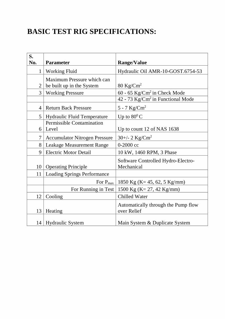
BASIC TEST RIG SPECIFICATIONS:
S.
No. Parameter Range/Value
1 Working Fluid Hydraulic Oil AMR-10-GOST.6754-53
2
Maximum Pressure which can
be built up in the System 80 Kg/Cm2
3 Working Pressure 60 - 65 Kg/Cm2 in Check Mode
42 - 73 Kg/Cm2 in Functional Mode
4 Return Back Pressure 5 - 7 Kg/Cm2
5 Hydraulic Fluid Temperature Up to 800 C
6
Permissible Contamination
Level Up to count 12 of NAS 1638
7 Accumulator Nitrogen Pressure 30+/- 2 Kg/Cm2
8 Leakage Measurement Range 0-2000 cc
9 Electric Motor Detail 10 kW, 1460 RPM, 3 Phase
10 Operating Principle
Software Controlled Hydro-Electro-
Mechanical
11 Loading Springs Performance
For Pmax 1850 Kg (K= 45, 62, 5 Kg/mm)
For Running in Test 1500 Kg (K= 27, 42 Kg/mm)
12 Cooling Chilled Water
13 Heating
Automatically through the Pump flow
over Relief
14 Hydraulic System Main System & Duplicate System

APPLICATION
Testing and Adjusting of Combined Control Unit of MI8 Helicopter.
The Test Rig is for carrying out acceptance, control & periodic test of Servo Units KAY-30B, PA-60B according to the specific Test Schedules of the components
TEST RIG LAYOUT & MAIN COMPONENTS
The complete Test Rig comprises of the following Sub Systems:
1. Hydraulics System
2. Mechanical System
3. Electronics, Instrumentation & Electrical System
4. DAS, Software & Control System
The Test Rig shall be installed in three parts:
1. Hydraulic Panel with Drip Tray & Work Bench
2. Hydraulic Power Pack which will be kept away from the
Item-1 above.
3. Electronics/DAS Industrial Cabinet.

Hydraulics System:
Hydraulic System is as per the Hydraulics Circuit Diagram & Hydraulics
Bill of Material.
It consists of identical Main System & Duplicate System. The System
consists of a SS Test Panel with Drip Tray. Control apparatus, Levers,
Hydraulic Supply/ Return Ports are mounted on this Panel. Measurement
Gauges for Manual Testing are installed on the Panel.
The Drip Tray/Test Table/Test Panel has drawers on both sides for the
operators to keep Fittings/ Spares/ Hydraulic Connectors/ Plugs and other
necessities needed to connect the Test Rig Equipment’s/ Components.
The Power Pack of the Hydraulic System is kept separate from the Test
Panel to avoid Noise/ Vibration and related disturbances during the
Testing.
Basic features of the Hydraulic System are as follows:
All Tubing/ Fittings are of Compression Type & certified material
SS 316 only.
All wetted part of Hydraulic System is of SS 316 only.
For all Connections (of the Test Components) with the Test panel
SS 316 QCDC are provided on the Test Panel.
Sampling Ports are provided for connecting Oil Quality Measuring
Instruments.
All Measuring Instruments/ Gauges have In Situ Calibration
facility through Ports.
All Selector valves are automatic and can be operated manually as
well.
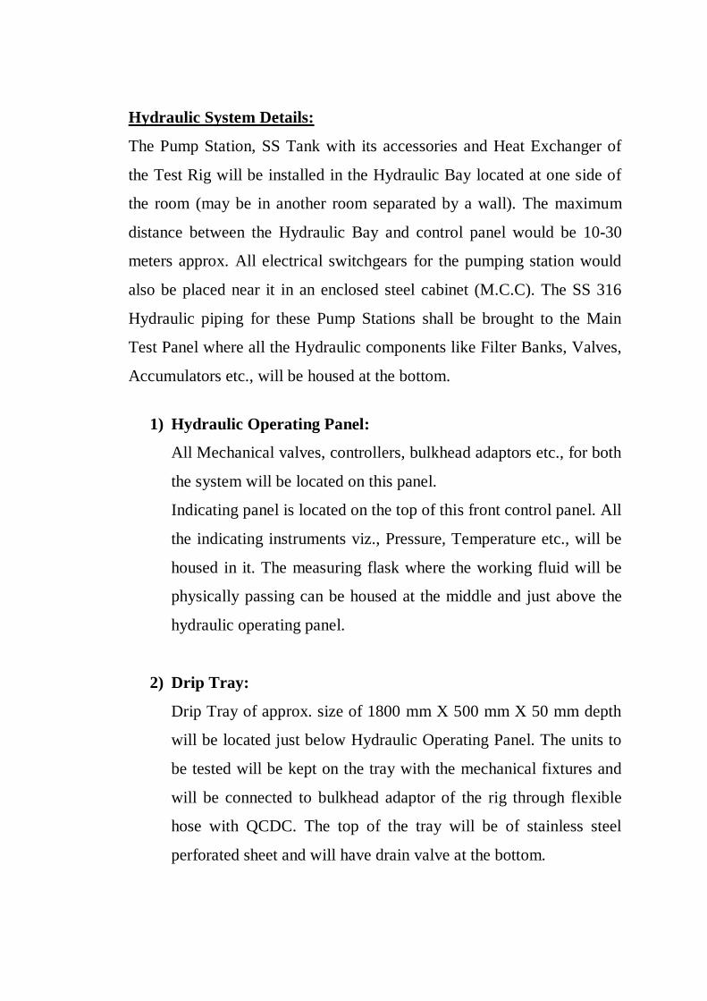
Hydraulic System Details:
The Pump Station, SS Tank with its accessories and Heat Exchanger of
the Test Rig will be installed in the Hydraulic Bay located at one side of
the room (may be in another room separated by a wall). The maximum
distance between the Hydraulic Bay and control panel would be 10-30
meters approx. All electrical switchgears for the pumping station would
also be placed near it in an enclosed steel cabinet (M.C.C). The SS 316
Hydraulic piping for these Pump Stations shall be brought to the Main
Test Panel where all the Hydraulic components like Filter Banks, Valves,
Accumulators etc., will be housed at the bottom.
1) Hydraulic Operating Panel:
All Mechanical valves, controllers, bulkhead adaptors etc., for both
the system will be located on this panel.
Indicating panel is located on the top of this front control panel. All
the indicating instruments viz., Pressure, Temperature etc., will be
housed in it. The measuring flask where the working fluid will be
physically passing can be housed at the middle and just above the
hydraulic operating panel.
2) Drip Tray:
Drip Tray of approx. size of 1800 mm X 500 mm X 50 mm depth
will be located just below Hydraulic Operating Panel. The units to
be tested will be kept on the tray with the mechanical fixtures and
will be connected to bulkhead adaptor of the rig through flexible
hose with QCDC. The top of the tray will be of stainless steel
perforated sheet and will have drain valve at the bottom.
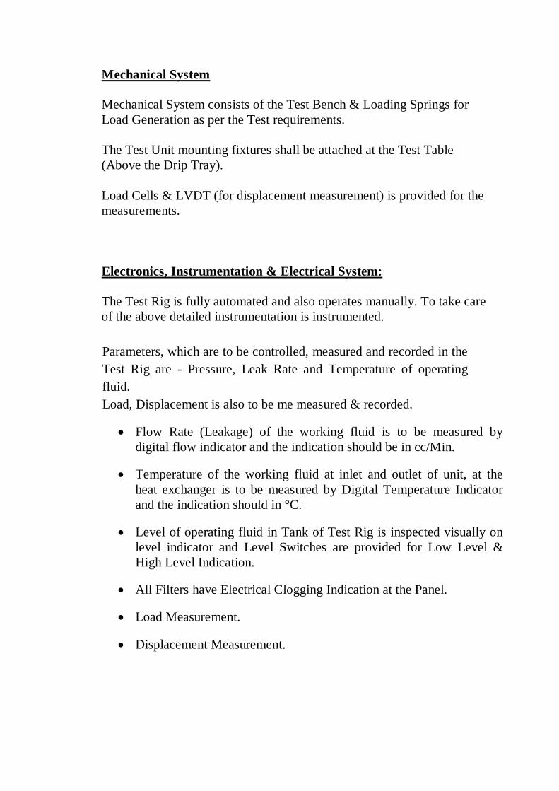
Mechanical System
Mechanical System consists of the Test Bench & Loading Springs for
Load Generation as per the Test requirements.
The Test Unit mounting fixtures shall be attached at the Test Table
(Above the Drip Tray).
Load Cells & LVDT (for displacement measurement) is provided for the
measurements.
Electronics, Instrumentation & Electrical System:
The Test Rig is fully automated and also operates manually. To take care
of the above detailed instrumentation is instrumented.
Parameters, which are to be controlled, measured and recorded in the
Test Rig are - Pressure, Leak Rate and Temperature of operating
fluid.
Load, Displacement is also to be me measured & recorded.
Flow Rate (Leakage) of the working fluid is to be measured by
digital flow indicator and the indication should be in cc/Min.
Temperature of the working fluid at inlet and outlet of unit, at the
heat exchanger is to be measured by Digital Temperature Indicator
and the indication should in °C.
Level of operating fluid in Tank of Test Rig is inspected visually on
level indicator and Level Switches are provided for Low Level &
High Level Indication.
All Filters have Electrical Clogging Indication at the Panel.
Load Measurement.
Displacement Measurement.
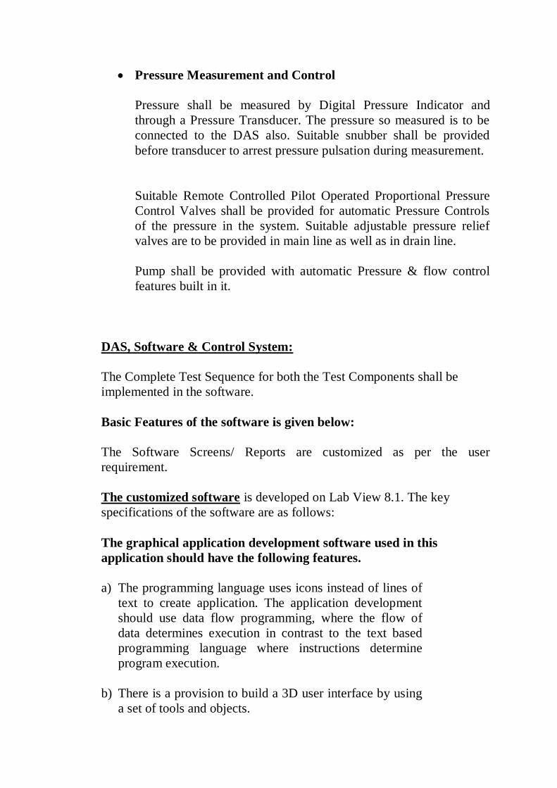
Pressure Measurement and Control
Pressure shall be measured by Digital Pressure Indicator and
through a Pressure Transducer. The pressure so measured is to be
connected to the DAS also. Suitable snubber shall be provided
before transducer to arrest pressure pulsation during measurement.
Suitable Remote Controlled Pilot Operated Proportional Pressure
Control Valves shall be provided for automatic Pressure Controls
of the pressure in the system. Suitable adjustable pressure relief
valves are to be provided in main line as well as in drain line.
Pump shall be provided with automatic Pressure & flow control
features built in it.
DAS, Software & Control System:
The Complete Test Sequence for both the Test Components shall be
implemented in the software.
Basic Features of the software is given below:
The Software Screens/ Reports are customized as per the user
requirement.
The customized software is developed on Lab View 8.1. The key
specifications of the software are as follows:
The graphical application development software used in this
application should have the following features.
a) The programming language uses icons instead of lines of
text to create application. The application development
should use data flow programming, where the flow of
data determines execution in contrast to the text based
programming language where instructions determine
program execution.
b) There is a provision to build a 3D user interface by using
a set of tools and objects.

c) The software is integrated fully for communication with
hardware such as GPIB, VXI, PXI, RS-232, RS-485 and
plug in DAQ device with the technologies such as MITE,
PGIA, and STC etc.
d) The software has built in feature for connecting the
application to the web using Web Server & software
standards such as TCP/IP, Data Socket, DLL, and SQL.
Networking and Active X.
e) The software has a true 32 bit compiler for faster
execution of the application
f) The software has a profile window as a tool for analyzing
as to how the application uses the execution time as well
as the memory so that the areas can be identified for
optimization.
g) The software will provide DAQ solution wizard for quick
start up. The software should execute with multithreading
features, de bugging features like break points, probes,
single stepping modes, execution-highlighting etc.
Software Features
The Test Rig is fully computerized and the application software
incorporates the basic minimum architecture as described below:
PC compatible hardware, COTS, Microsoft Windows 98 (or equal)
Operating System, COTS
SYSTEM OPERATION:
The software function is basically categorized into two distinct modes of
system operation.
- System Maintenance Mode: That includes calibration of sensors,
system diagnostics, fault diagnostics etc
- Test Part (UUT) Test Mode: Test part Test Run mode during
which the UUT – test part is undergoing the dynamic testing.

SYSTEM MAINTENANCE MODE:
The system maintenance mode comprises of certain functions that
mainly consists of system setup routines. These routines are done
either periodically (e.g.: calibration of sensors), or done on demand
(e.g.: diagnostics, troubleshooting etc.).
SENSOR (TRANSDUCER) CALIBRATION:
The systems should allow calibration which includes Analog
Input/Output and frequency Input / Output. In this mode, all sensors –
pressure transducers, Load Cells, Displacement Transducers, flow
meters, temperature sensors, etc. – are calibrated and stored in
respective tables for use in the test run mode.
SYSTEM DIAGNOSTICS:
The software allows the user to perform System Diagnostics, Fault
Isolation and Correction. The Fault Isolation will be done in a
computer assisted mode – where various stimuli can be actuated and
the responses displayed by the computer - or in a manual mode –
where the application of stimuli is done by manual switches and the
computer displaying the responses. This function is available for all
the Data Acquisition points including Analog, Digital and Frequency
Inputs/Outputs, Waveform generators, etc.
TEST RIG DIAGNOSTICS / TROUBLESHOOTING:
The Test Rig software allows the user to perform Diagnostics. It will
enable the user to troubleshoot Analog and Digital Input / Outputs.
When the test stand power is ON and the diagnostics mode is selected
and Analog Input option is chosen, all applicable parameters shall be
continuously monitored, measured and displayed in terms of volts,
binary counts and engineering values.
TEST PART (UUT) TEST MODE:
This is the Main System Operation Mode. This function will
encompass all the Run Time operations. This function is re-
configurable and gives the user flexibility and operational efficiency:

AUTOMATIC MODE:
The operator is able to select a test part (UUT) from the 17” TFT
TOUCH SCREEN Menu. The operator enters the applicable UUT
serial number. The test stand 17” TFT TOUCH SCREEN will present
the operator with various test paragraphs applicable to the selected
UUT. The operator is able to select the test paragraphs in the order he
wishes to test the UUT. Test Actions corresponding to each test
paragraph are conducted automatically without any operator input for
set points or for accept/reject. All sub-systems function in unison to
achieve the required performance.
The software is single executable a state-of-the-art, user friendly, FAA
friendly software and must work with standard PCs and operates
under all versions of Windows and their natural successors with or
without expensive peripherals and should follow all rules necessary to
maintain full upward compatibility with future PCs and operating
systems.
The software supports test stand operation in Fully Automatic and
Manual modes.
The software supports at least 16 levels of password protection to
enable various levels of authority and access to operation,
programming, safety protection, and reconfiguration. The command
structure shall be based on Standard English using standard Excel type
spreadsheets for implementing test code.
The software is user-friendly, color graphic, point-and-click
operations and conforms to PC/Windows technology for easy operator
training. It provides on-screen messages
provides on-screen messages and prompts so to make the test an
interactive process further minimizing training needs. It supports up to
two color displays, allowing simultaneous reading of test set point and
measured test data.
Unit protection functions are built in. Each set point and measured
parameter shall be checked continuously for safe operating range. The
Protection set points allow three levels of action:

Some Indicative Software Screens (Not of this system) are given below for
reference
Test Rig Software: Test Rig: Maintenance Mode
A typical Maintenance screen looks like the one below (This is an example
taken from some other project)
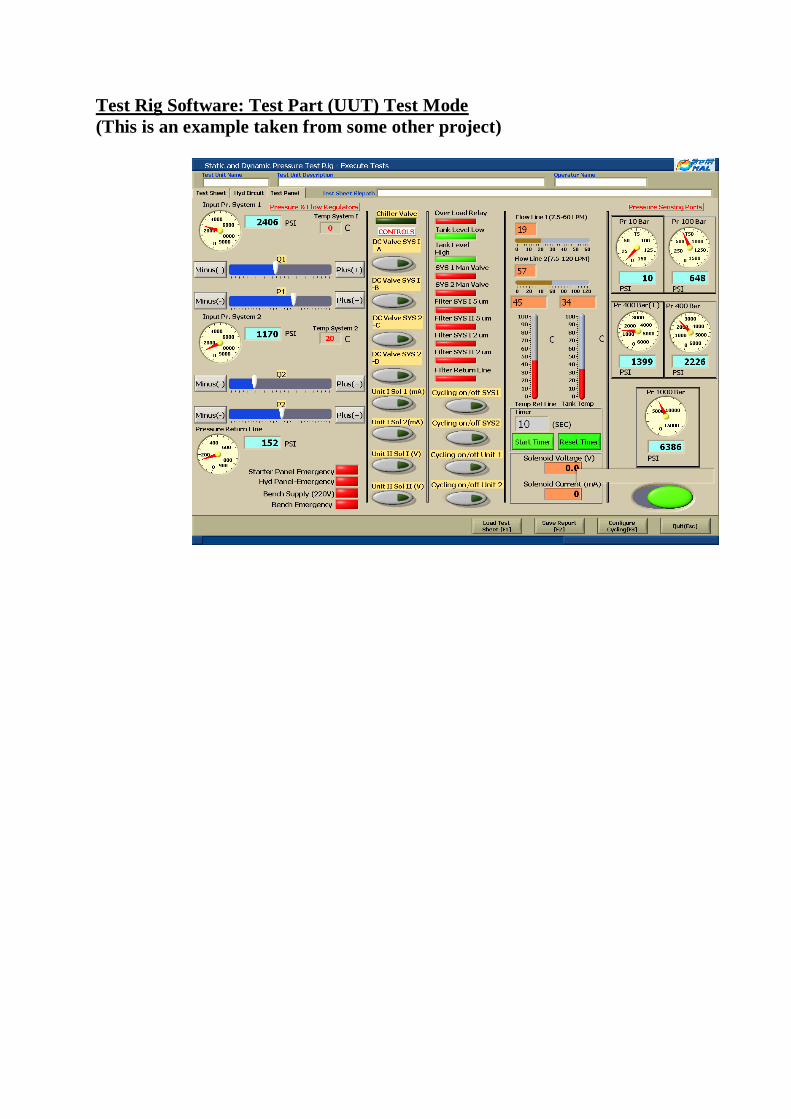
Test Rig Software: Test Part (UUT) Test Mode
(This is an example taken from some other project)
