cctv systems upgrade incl. wireless transmission and · pdf fileborough council technical...
TRANSCRIPT

CCTV Systems Upgrade incl. Wireless Transmission and New
Control Room for St Edmundsbury Borough Counci l
Technical Performance Specif icat ion (Revised Scope)
P r e p a r e d b y :
CDC Technical Services Ltd for
St Edmundsbury Borough Counci l
Date - 22 January 2015

St Edmundsbury Borough Council: CCTV Systems Upgrade incl. Wireless Transmission and New Control Room Technical Performance Specification – Revised Scope
© CDC Technical Services Ltd 2015 22 January 2015 Page 2 of 65
DOCUMENT CONTROL
This document has been prepared for St Edmundsbury Borough Council for the purpose outlined within the document and in line with the instructions commissioning it. This document is issued in commercial confidence and should be read in conjunction with all other contract specific documents and drawings.
ORIGINATOR
Original Document Prepared By: Car l Chippendale
Signature:
Date: September 2014
REVISION HISTORY
Rev Descript ion By Date
6 Initial Tender Issue (Dec 2014) CC Dec 2014
7
Document amended in accordance with a revised scope of works in the following sections –
• 3.2 – revised wording; • 3.5 & 3.6 – revised specification; • 3.9 – revised wording; • 4.1, 4.4 & 4.11 revised specification; • 4.5, 4.6 & 4.12 – revised wording; • 4.18 – revised specification (for legacy
equipment); • 4.24 revised for clarity; • 5.3, 5.4, 5.9 & 5.11 – revised
specification; • 9.1 – revised specification; • 10.8 – revised wording;
CC Jan 2015
St Edmundsbury Borough Council: CCTV Systems Upgrade incl. Wireless Transmission and New Control Room Technical Performance Specification – Revised Scope
© CDC Technical Services Ltd 2015 22 January 2015 Page 3 of 65
Table of Contents
DOCUMENT CONTROL ..................................................................................................... 2 ORIGINATOR ..................................................................................................................... 2 REVISION HISTORY .......................................................................................................... 2
INTRODUCTION ..................................................................................... 7 Section 1.1.1 GENERAL OVERVIEW .............................................................................................. 7 1.2 DESIGN BRIEF .......................................................................................................... 7 1.3 NAMES OF PARTIES ................................................................................................ 9 1.4 DESCRIPTION OF SITES .......................................................................................... 9
GENERAL INSTALLATION REQUIREMENTS ..................................... 10 Section 2.2.1 DILAPIDATION SURVEY ......................................................................................... 10 2.2 COAX VIDEO CABLING .......................................................................................... 10 2.3 TWISTED PAIR CABLING ....................................................................................... 10 2.4 JOINTS IN CABLES ................................................................................................ 11 2.5 ELECTRICAL INSTALLATION REQUIREMENTS ...................................................... 11 2.6 MAINS DISTRIBUTION ............................................................................................ 12 2.7 POWER CIRCUITS .................................................................................................. 12 2.8 EQUIPMENT RACKS .............................................................................................. 12 2.9 UNINTERRUPTABLE POWER SUPPLY UNITS ....................................................... 13 2.10 ELECTRICAL CERTIFICATION ................................................................................ 14 2.11 CABLE & CONTAINMENT ....................................................................................... 14 2.12 EARTH BONDING ................................................................................................... 14 2.13 LIGHTNING PROTECTION ...................................................................................... 14 2.14 LABELLING ............................................................................................................. 15 2.15 VANDALISM PROTECTION ..................................................................................... 15 2.16 MAKING GOOD FOLLOWING INSTALLATION ........................................................ 15 2.17 FIRE STOPPING ..................................................................................................... 16 2.18 SITE ACCOMMODATION ........................................................................................ 16 2.19 DISPOSAL OF WASTE ............................................................................................ 16
CCTV SYSTEMS ................................................................................... 17 Section 3.3.1 GENERAL ............................................................................................................... 17 3.2 NEW SYSTEMS OVERVIEW ................................................................................... 17 3.3 NEW CAMERA CONFIGURATION SUMMARY ........................................................ 17 3.4 LEGACY SYSTEMS ................................................................................................ 18 3.5 EXTERNAL RUGGEDISED ANALOGUE PTZ CAMERAS ......................................... 20 3.6 EXTERNAL RUGGEDISED IP PTZ CAMERAS ......................................................... 21 3.7 STATIC IP CAMERAS ............................................................................................. 21

St Edmundsbury Borough Council: CCTV Systems Upgrade incl. Wireless Transmission and New Control Room Technical Performance Specification – Revised Scope
© CDC Technical Services Ltd 2015 22 January 2015 Page 4 of 65
3.8 STATIC ANALOGUE CAMERAS .............................................................................. 22 3.9 REDEPLOYABLE CAMERAS .................................................................................. 23 3.10 CAMERA BRACKETRY ........................................................................................... 23 3.11 SUPPLEMENTARY LIGHTING ................................................................................ 23
CONTROL, RECORDING & DISPLAY SYSTEMS ................................ 24 Section 4.4.1 NETWORKED VIDEO RECORDING SYSTEM .......................................................... 24 4.2 MOTION DETECTION RECORDING ........................................................................ 25 4.3 TIME SCHEDULED RECORDING ............................................................................ 25 4.4 H.264 VIDEO ENCODING ....................................................................................... 25 4.5 EXISTING DIGITAL RECORDERS ............................................................................ 26 4.6 CONTROL ROOM MANAGEMENT SYSTEM (CRMS) .............................................. 27 4.7 CRMS ALARM MONITORING ................................................................................. 28 4.8 CRMS 3RD PARTY INTEGRATION ........................................................................... 28 4.9 CRMS REVIEW SYSTEM ........................................................................................ 28 4.10 CRMS EVENT RECORDING .................................................................................... 29 4.11 CRMS EVIDENCE LOCKER .................................................................................... 29 4.12 INCIDENT MANAGEMENT & REPORTING FEATURES ........................................... 29 4.13 CRMS DATABASE BACK UP .................................................................................. 30 4.14 PROCESS MANAGEMENT WORKFLOWS .............................................................. 30 4.15 ‘FOLLOW ME’ ANALOGUE VIDEO OUTPUTS ........................................................ 31 4.16 ‘FOLLOW ME’ ANALOGUE VIDEO INPUTS ............................................................ 31 4.17 SYNECTICS SYSTEMS CONTROL ......................................................................... 31 4.18 DIGITAL VIDEO DISPLAY SYSTEM ......................................................................... 31 4.19 OPERATOR DESK MONITORS ............................................................................... 32 4.20 CAMERA CONTROL KEYBOARD/JOYSTICK ......................................................... 33 4.21 MULTI-FUNCTION PRINTER FACILITY ................................................................... 33 4.22 NETWORK TIME SERVER & CLOCK DISPLAY ....................................................... 34 4.23 REMOTE ACCESS TO CCTV SYSTEMS ................................................................. 34 4.24 MANUFACTURER ‘BUY BACK’ .............................................................................. 34
TRANSMISSION NETWORK ................................................................ 35 Section 5.5.1 SUMMARY .............................................................................................................. 35 5.2 NEW FIBRE NETWORK LINKS ............................................................................... 35 5.3 LOCAL AREA NETWORKS ..................................................................................... 36 5.4 NETWORK SWITCHES ........................................................................................... 37 5.5 VLANS .................................................................................................................... 38 5.6 WEST SUFFOLK ICT ............................................................................................... 38 5.7 WIRELESS NETWORK DESIGN CONCEPT ............................................................ 39 5.8 WIRELESS NETWORK DESIGN - SCHEMATICS .................................................... 39 5.9 NETWORK BACKHAUL LINKS ............................................................................... 40
St Edmundsbury Borough Council: CCTV Systems Upgrade incl. Wireless Transmission and New Control Room Technical Performance Specification – Revised Scope
© CDC Technical Services Ltd 2015 22 January 2015 Page 5 of 65
5.10 UNLICENSED WIRELESS LINKS ............................................................................ 41 5.11 POINTS OF PRESENCE .......................................................................................... 42 5.12 VARIABLE MESSAGE SIGNS CONNECTIVITY ........................................................ 44 5.13 REDEPLOYABLE CAMERA CONNECTIVITY ........................................................... 45 5.14 ROOFTOP ANTENNA BRACKETRY ........................................................................ 45 5.15 UP-STAND BRACKETS .......................................................................................... 45 5.16 SURGE AND LIGHTNING PROTECTION ................................................................. 46 5.17 EXISTING OFDM REDEPLOYABLE NETWORK ....................................................... 46
CONTROL ROOM WORKS .................................................................. 47 Section 6.6.1 GENERAL INFORMATION ....................................................................................... 47 6.2 CONTROL ROOM ELECTRICAL WORKS ............................................................... 47 6.3 LOCAL AREA NETWORK ....................................................................................... 48 6.4 KVM EXTENSION .................................................................................................... 48 6.5 DATA CENTRE EQUIPMENT RACKS ...................................................................... 48 6.6 IT LAN & TELEPHONY ............................................................................................ 49 6.7 SHOPSAFE RADIO ................................................................................................. 49 6.8 AIRWAVE RADIO .................................................................................................... 49
DOCUMENTATION ............................................................................... 50 Section 7.7.1 GENERAL ............................................................................................................... 50 7.2 ASSET REGISTER .................................................................................................. 50 7.3 DESIGN DRAWINGS ............................................................................................... 50 7.4 SYSTEM & PRODUCT DATA .................................................................................. 50 7.5 CONTRACT CLOSE OUT SUBMITTALS ................................................................. 51 7.6 MANUALS .............................................................................................................. 51
COMPLETION & HANDOVER .............................................................. 53 Section 8.8.1 SITE WITNESS TESTING ........................................................................................ 53 8.2 TRAINING ............................................................................................................... 53 8.3 FINAL ACCEPTANCE / HANDOVER ....................................................................... 53 8.4 COMPLETION ......................................................................................................... 54 8.5 DEFECTS WARRANTY PERIOD .............................................................................. 54
SERVICE AND MAINTENANCE ........................................................... 55 Section 9.9.1 GENERAL ............................................................................................................... 55 9.2 EQUIPMENT REPLACEMENT OR REPAIR COSTS ................................................. 55 9.3 VANDALISM ............................................................................................................ 56 9.4 PLANNED PREVENTATIVE MAINTENANCE (PPM) ................................................. 56 9.5 PPM SCHEDULE OF TASKS .................................................................................. 56 9.6 EQUIPMENT COVERED IN PPM ............................................................................. 57 9.7 CONTROL ROOM EQUIPMENT AND EQUIPMENT RACKS .................................... 58

St Edmundsbury Borough Council: CCTV Systems Upgrade incl. Wireless Transmission and New Control Room Technical Performance Specification – Revised Scope
© CDC Technical Services Ltd 2015 22 January 2015 Page 6 of 65
9.8 SYSTEM BACK-UPS .............................................................................................. 58 9.9 OPERATOR & MAINTENANCE (O&M) INFORMATION ............................................ 59 9.10 PPM PROGRAM OF WORKS .................................................................................. 59 9.11 PPM SITE ATTENDANCE ........................................................................................ 59 9.12 CONTRACT ADDITIONS/DELETIONS ..................................................................... 59
REPORTING & MONITORING ............................................................ 61 Section 10.10.1 FAULT REPORTING ................................................................................................ 61 10.2 SERVICE RECORDS ............................................................................................... 61 10.3 RESPONSE TIMES ................................................................................................. 62 10.4 COMPLETION/SIGN-OFF OF WORKS. ................................................................... 63 10.5 DEFAULT IN PERFORMANCE ................................................................................ 64 10.6 CONTRACTOR DEFAULT EXEMPTION .................................................................. 64 10.7 PERFORMANCE PENALTIES .................................................................................. 64 10.8 TERMINATION ........................................................................................................ 65 10.9 MONTHLY REPORTING .......................................................................................... 65 10.10 KPI REVIEW ...................................................................................................... 65

St Edmundsbury Borough Council: CCTV Systems Upgrade incl. Wireless Transmission and New Control Room Technical Performance Specification – Revised Scope
© CDC Technical Services Ltd 2015 22 January 2015 Page 7 of 65
INTRODUCTION Section 1.1.1 GENERAL OVERVIEW
The current public-space CCTV system at St Edmundsbury Borough Council (SEBC) is one that has evolved over the last two decades (since 1995) to respond to variations in the thinking and requirements of the times and at present is in need of updating and modernising to make use of new technology. The system itself is predominantly based around leased fibre-optic video circuits from BT, which provide high quality analogue video links, but limit the flexibility of the system in terms of responding to changes in camera coverage and the ability to utilise rapid-deployment cameras for short-term incident monitoring. As part of a recent business case outlining the benefits of wireless transmission, in terms of reducing the Council’s operational expenditure and the potential for additional revenue streams from 3rd party monitoring opportunities, a decision has been taken to upgrade the CCTV monitoring service and implement a new wireless transmission network around the towns of Bury St Edmunds and Haverhill along with a significant upgrade in control and recording systems and a relocation of the CCTV control room to the Council’s new offices at West Suffolk House in Bury St Edmunds. This tender package and performance specification has been compiled to address the issues raised by the Council and provide a new digital solution based around the supply, installation and commissioning of a new digital wireless network, the relocation of the CCTV control room and the supply, installation and commissioning of new modern digital CCTV control and recording systems. Where remaining budget exists, the Council wishes to upgrade its existing camera equipment in line with improvements in technology such as high definition (HD) and megapixel imaging. A new 3-year service and maintenance package has been included within the requirements of this tender package to include all new systems as outlined above plus all legacy systems that form part of the Bury St Edmunds public space CCTV monitoring service.
1.2 DESIGN BRIEF
In summary, the Contractor shall provide the following elements of work –
• A new digital wireless transmission network; • A new digital CCTV control and recording system; • Relocation of the existing CCTV control room with new fit-out of control room furniture; • Equipment upgrade of selected CCTV camera locations throughout the scheme; • Integration of all legacy systems from remote towns; • 3-year service and maintenance of all systems and equipment;
The Contractor shall also be responsible for all works in relation to any decommissioning and strip out of the existing site as per the requirements outlined in these tender documents. All work shall be undertaken in accordance with the requirements of the following (but not limited to) –
• The Home Office Surveillance Camera Code of Practice 2013; • The BSIA Form No. 109 – CCTV Surveillance System Code of Practice and Associated
Guidelines Issue 3 (2014);

St Edmundsbury Borough Council: CCTV Systems Upgrade incl. Wireless Transmission and New Control Room Technical Performance Specification – Revised Scope
© CDC Technical Services Ltd 2015 22 January 2015 Page 8 of 65
• BS EN 50132-7: 2012 – Alarm systems. CCTV surveillance systems for use in security applications. Application guidelines;
• The latest version of the 17th Edition IEE Wiring Regulations, BS7671: 2008 (2011); • All relevant British Standards & Codes of Practice; • All relevant Building Regulations; • Construction (Design and Management) Regulations 2007; • Health & Safety at Work Act 1974; • Working at Height Regulations 2005; • CIBSE Guidelines (where applicable); • Control of Substances Hazardous to Health (COSHH) Regulations 2002; • The Waste Electrical and Electronic Equipment (WEEE) Regulations 2013; • Article 6 of the Energy Efficiency Directive 2012; • Any specific requirements of the local Fire Prevention Officer and/or Building Control
officer; • CDM coordinator Pre-construction information; • All other relevant SEBC and West Suffolk documents relating to this ITT;
It shall be noted that this specification should be read in accordance with all the following documents that form part of this invitation to tender (ITT) –
• SEBC: CCTV Systems Upgrade incl. Wireless Transmission and New Control Room: Technical Performance Specification – Rev. 7 Revised Scope (this document);
• SEBC: CCTV Systems Upgrade incl. Wireless Transmission and New Control Room: Technical Performance Specification Appendices – Rev. 3 Revised Scope;
• SEBC: CCTV Systems Upgrade incl. Wireless Transmission and New Control Room: Pricing Schedule – Rev.4 Revised Scope;
• Drawing No. CDC_SEBC_SYSTEMS-SCH01: Systems Concept Schematic; • Drawing No. CDC_SEBC_WIRELESS_01: Bury St Edmunds Wireless Backhaul
Concept Schematic; • Drawing No. CDC_SEBC_WIRELESS_02: West Suffolk House Rooftop Point of
Presence Schematic; • Drawing No. CDC_SEBC_WIRELESS_03: Parkway MSCP Rooftop Point of Presence
Schematic; • Drawing No. CDC_SEBC_WIRELESS_04: Apex Rooftop Point of Presence Schematic; • Drawing No. CDC_SEBC_WIRELESS_05: Haverhill Wireless Concept Schematic (Part 1
of 2); • Drawing No. CDC_SEBC_WIRELESS_06: Haverhill Wireless Concept Schematic (Part 2
of 2);
The project will be notified to the Health and Safety Executive under the Construction (Design and Management) Regulations 2007 and the appointed contractor will be expected to assume the role of PRINCIPAL CONTRACTOR. The Employer’s appointed CDM coordinator (CDMC) shall submit the F10 and update as required as soon as a contractor is appointed.

St Edmundsbury Borough Council: CCTV Systems Upgrade incl. Wireless Transmission and New Control Room Technical Performance Specification – Revised Scope
© CDC Technical Services Ltd 2015 22 January 2015 Page 9 of 65
1.3 NAMES OF PARTIES
Employer – Teresa Claydon St Edmundsbury Borough Council T – 01284 757398 E – [email protected]
Technical Consultant – Hereinafter known as the ‘Employer’s Representative’ Carl Chippendale CDC Technical Services Ltd T – 07951 944911 E – [email protected]
CDM Coordinator – Hereinafter known as the ‘CDMC’
Ben Mulley DMA Health and Safety Limited T – 01359 244830 E – [email protected]
1.4 DESCRIPTION OF SITES
The sites to be considered under this contract are listed in more detail within Appendices of this document, but in general are those sites owned and/or managed by St Edmundsbury Borough Council and are spread throughout the borough. In summary the sites comprise the following (but not limited to) –
• West Suffolk House new CCTV control room; • Parkway MSCP existing CCTV control room; • Bury St Edmunds public-space CCTV scheme; • Haverhill public-space CCTV scheme; • Parkway MSCP Car Park, Bury St Edmunds; • Rooftop of the Apex, Bury St Edmunds; • Rooftop of the Corn Exchange, Bury St Edmunds; • Rooftop of the Athenaeum, Bury St Edmunds; • Rooftop of the Haverhill House Council Offices, Haverhill; • Rooftop of the Leisure Centre, Haverhill; • Rooftop of Strasbourg Square, Haverhill;

St Edmundsbury Borough Council: CCTV Systems Upgrade incl. Wireless Transmission and New Control Room Technical Performance Specification – Revised Scope
© CDC Technical Services Ltd 2015 22 January 2015 Page 10 of 65
GENERAL INSTALLATION REQUIREMENTS Section 2.2.1 DILAPIDATION SURVEY
Prior to the commencement of works, the Contractor is advised to undertake their own dilapidation survey to ensure that any legacy faults or issues are identified and reported at the start of the project. Where possible, the Employer shall assist with this process to ensure that all previously reported and identified faults have been captured. A copy of the dilapidation report shall be submitted to the Employer as soon as it is complete. The Contractor shall note that failure to undertake this survey or identify existing or legacy faults/issues, may result in said faults/issues being included as part of the project snagging works and as such may affect handover of the project or the issue of Completion.
2.2 COAX VIDEO CABLING
Where applicable, copper video cable shall be of 75-ohm impedance characteristic and chosen to suit the length and type of cable run per camera location. Routing to and from a camera, monitor, fibre optic transmitter or receiver and any composite video unit shall be on RG59 (or equivalent) up to 250 metres maximum length. The use of RG11 or equivalent cable shall be used on routes of more than 250 metres. The cable loss shall not under any circumstances exceed 6dB @ 5.5MHz per camera cable feed and it shall be the responsibility of the Contractor to provide suitable compensation if necessary to ensure the correct input levels are present at the control equipment. Within equipment cabinets, cable, which offers greater radial bend flexibility including URM70 and RG59/Mini shall be acceptable provided these cables are not joined to incoming main RG59 or RG11 runs. Correctly terminated loop through or video distribution male BNC outlets shall be used for the transfer of cable type(s). Any cable feed underground, in external conduit, or surface clipped, shall be sheathed in polyethylene and if exposed, ruggedized to afford extra physical protection. Video signals shall be free of earth differential faults and the use of isolation transformers is discouraged. The correct type of BNC connectors shall be used and all connectors SHALL be fitted with a colour co-ordinated strain relief where possible and labelled as per the requirements detailed later in this specification.
2.3 TWISTED PAIR CABLING
Where applicable, the Contractor may consider that a twisted pair solution would be more economically advantageous than using copper coaxial cabling per camera. This method shall be permitted subject to the chosen solution providing a 75-ohm composite video output of 1 volt peak-to-peak @ 5.5MHz. For this solution, UTP CCTV the video transceiver devices provided shall be capable of transmitting and receiving base band monochrome or colour video signals over unshielded twisted-pair (UTP) CAT5e cable to a passive transceiver up to a distance of 225m without requiring power at either end.

St Edmundsbury Borough Council: CCTV Systems Upgrade incl. Wireless Transmission and New Control Room Technical Performance Specification – Revised Scope
© CDC Technical Services Ltd 2015 22 January 2015 Page 11 of 65
Distances up to 1,000m shall be supported when used in conjunction with an amplified (active) transceivers. Each transceiver shall have built in transient protection without the need for a ground connection. The transceiver(s) selected shall have a typical common mode rejection of 60dB between frequencies of 15KHz to 5MHz and a frequency response from DC to 5MHz. Amplifiers shall be rejected if the bandwidth or noise figure is not maintained. Where multiple transceivers are installed in the same location they shall be rack mounted or of modular design.
2.4 JOINTS IN CABLES
Joints in cables shall be avoided wherever possible by choosing suitable cable drum lengths to ensure cable runs continuously connect source (“e.g. camera”) to destination equipment (“e.g. digital recording system”). Any joints that are unavoidable SHALL be brought to the attention of the Employer and shall be made using proprietary boxes or jointing kits to ensure a fully durable and waterproof seal. Such joints shall be mechanically protected to prevent physical stress and strain on the joint itself. The location of joints shall be selected to ensure easy access by service and maintenance personnel, particularly for fault-finding purposes. The locations of all such joints shall be recorded on the ‘As Fitted’ drawings for future reference.
2.5 ELECTRICAL INSTALLATION REQUIREMENTS
Where electrical installation is necessary, the Contractor shall be responsible for and include costs associated with all works required in accordance with the following –
• All electrical work is to be carried out by a NICEIC approved electrician(s) and shall conform to the latest version of the 17th Edition IEE Wiring Regulations, BS 7671: 2008 (2011);
• All lighting design shall be carried out in accordance with the CIBSE Code for Internal Lighting, emergency lighting in accordance with CIBSE LG7, TM12, BS 5266 and EN 60-2-22;
• All power circuits shall be designed in accordance with the 17th Edition IEE Wiring Regulations, BS 7671: 2008 (2011);
• Commissioning process completed in accordance with relevant CIBSE, BRE and BSRIA recommended codes of practice;
• Fire alarm in accordance with BS 5839 Part I: 2002. (Category P2); • Emergency lighting in compliance with BS 5266 and CIBSE Lighting Guide 12; • All working drawings and final 'As Installed' drawings shall be produced in a .dwg
format.

St Edmundsbury Borough Council: CCTV Systems Upgrade incl. Wireless Transmission and New Control Room Technical Performance Specification – Revised Scope
© CDC Technical Services Ltd 2015 22 January 2015 Page 12 of 65
2.6 MAINS DISTRIBUTION
Mains distribution at all specified locations shall be designed in accordance with the following requirements: -
• Main switchboards, sectional switchboards and distribution boards shall be appropriate in terms of all electrical and mechanical criteria. The switchgear shall provide for future extension affecting cabling and electrical loads up to a minimum of [10%] above the base load for the completed project;
• All switchboards and distribution boards shall be installed in secure locations; • All equipment and switchgear shall be provided with engraved labels, clearly marked
with details of the equipment’s function and designation; • Power factor correction shall be consistent with the aims of best practice energy
conservation throughout the contract period. • All low voltage (LV) systems functional with fuses and circuit breakers of the correct size,
RCD's fitted where applicable and the units and circuits tested in accordance with current electrical legislation.
2.7 POWER CIRCUITS
Where applicable, power circuits at all specified locations shall be designed in accordance with the following requirements: -
• The Contractor shall provide suitable RCBO / RCD protection against electric shock and circuit overload for all socket outlets. All 230V socket outlets shall be protected by 30mA RCBO’s;
• 230V 32A commando type sockets shall be provided shall be provided for all equipment racks with a suitable ‘plug’ and wired on individual radial circuits;
• The power circuit system shall be designed to minimise interference to computers caused by electrical faults or failures. The Contractor shall provide an appropriate number and distribution of sockets for all hardware components within the system, plus a number of spare sockets to allow for future expansion;
• The power circuits within the Security Console desk shall be fed from the UPS unit and, where applicable, be installed within a suitable containment system (i.e. Dado trunking or similar)
• All electrical socket outlets shall be free from cracks and securely fixed to back boxes; • All LV systems shall be functional with fuses and circuit breakers of the correct size,
RCD’s fitted where applicable and the units and circuits tested in accordance with the current electrical legislation.
2.8 EQUIPMENT RACKS
The Contractor shall utilize existing equipment racks wherever possible and it is expected that any existing equipment shall be relocated within the rack space available to provide a more intuitive and simple rack layout that is easier to service and maintain. The Contractor shall ensure that expansion space is available within the equipment racks wherever possible. The Contractor shall ensure sufficient mains power sockets are installed within the equipment racks and shall install additional power distribution units as required – the use of multi-gang extension sockets is not acceptable. A minimum of 25% future expansion capacity shall be provided (ratio based on used power sockets: total power sockets).

St Edmundsbury Borough Council: CCTV Systems Upgrade incl. Wireless Transmission and New Control Room Technical Performance Specification – Revised Scope
© CDC Technical Services Ltd 2015 22 January 2015 Page 13 of 65
Standard specifications for any new equipment cabinets are detailed below –
• Cabinets shall be manufactured in accordance with IEC 297 specifications; • Minimum size of 600mm (Width) x 800mm (Depth) but where applicable, sized to suit
the hardware being installed within the rack; • Wire mesh front and rear cabinet doors, Lockable with minimum of 4 keys; • Extraction fan unit mounted into top of cabinet; • Sufficient power supply outlets for the size of cabinet, allowing 25% hardware expansion
capability; • Suitable containment system within the cabinet for all cabling allowing for minimum 25%
expansion capability; • Adjustable rack frame; • Side and back panels to be fitted and secured where applicable; • Adjustable feet/or plinth where appropriate. Transport wheels shall be removed; • All cabinets shall be earthed in accordance with the latest IEE Wiring Regulations
(BS7671);
2.9 UNINTERRUPTABLE POWER SUPPLY UNITS
West Suffo lk House The Contractor shall not be responsible for any works associated with the UPS at West Suffolk House. Upgrades to the UPS shall be arranged and organised by the Employer as part of the fit out of the control room space. In addition, all new 230VAC mains power supplies within the new control room that are deemed necessary to be UPS supported shall be provided as part of the fit-out of the control room. Parkway MSCP The Contractor shall note that the existing UPS within the Parkway MSCP shall be retained. All new and existing equipment within the new hub shall be supported by the existing UPS. This shall include (but not be limited to) -
• New digital recording systems; • New digital encoding and decoding systems; • Network switches; • Wireless transmission equipment; • Existing UTP transmission equipment; • Existing BT transmission equipment; • Existing air conditioning equipment;
Haverhi l l House The Contractor shall supply and install a new rack-mounted UPS within the new equipment rack in the basement comms room at Haverhill House. The new UPS shall provide back-up power to support all equipment within the rack for a minimum of 10 minutes. Newmarket The Contractor shall note that the existing UPS within the Newmarket hub shall be retained and that the existing UPS shall support all existing equipment within the hub.

St Edmundsbury Borough Council: CCTV Systems Upgrade incl. Wireless Transmission and New Control Room Technical Performance Specification – Revised Scope
© CDC Technical Services Ltd 2015 22 January 2015 Page 14 of 65
Remote Monitor ing The Contractor shall provide a simple means of monitoring the status of the UPS units at Parkway MSCP, Haverhill House and Newmarket remote sites. All remote alarm monitoring (via simple alarm outputs or equivalent) shall be monitored by the chosen management system installed within the control room and shall provide immediate indication to the security operators of any fault(s) on the unit(s).
2.10 ELECTRICAL CERTIFICATION
Where new electrical installations exist, the Contractor shall submit test and completion certificates as required by the 17th Edition of the IEE Wiring Regulations to the Employer and/or Employer’s Representative. Test and Completion certificates shall be required for all new and modified circuits
Copies of the test certificates shall be issued to the Employer and/or Employer’s Representative within 3 days of the completion of the test.
Original copies of the certificates shall be issued as part of the Operation and Maintenance Manuals.
2.11 CABLE & CONTAINMENT
All cables and the associated cable containment systems are to be installed to satisfy the latest version of the 17th Edition IEE Wiring Regulations, BS7671: 2008 (2011). Data or video cabling shall NOT be mixed with power or other inappropriate types/categories of cables as defined within the above regulations. Existing cable containment installed within the buildings can be used wherever possible provided that spare capacity is available within the containment. The containment can be extended as necessary to new locations and the type of containment used shall be of the same material as the existing. No “loose-laying” or “clipping direct” of any cables to building fabric surfaces shall be acceptable on this project. The Employer and/or Employer’s Representative shall approve the containment system design prior to installation.
2.12 EARTH BONDING
All metalwork shall be fully earth bonded in accordance with the latest version of the 17th Edition IEE Wiring Regulations, BS7671: 2008 (2011).
2.13 LIGHTNING PROTECTION
Where applicable, the Contractor shall allow for bonding of all rooftop equipment (including any metal containment) to the existing building lightning protection system down conductor. Lightning protection shall comply with latest standard BS EN 62305. Professional technical advice should be sought where necessary in order to ensure compliance.

St Edmundsbury Borough Council: CCTV Systems Upgrade incl. Wireless Transmission and New Control Room Technical Performance Specification – Revised Scope
© CDC Technical Services Ltd 2015 22 January 2015 Page 15 of 65
2.14 LABELLING
All diagrams, charts, tables, labelling systems, label types and the wording for labels and notices shall be submitted for the approval of the Employer and /or Employer’s Representative prior to ordering. Both ends of ALL cables shall be labelled indicating the local and remote end destinations. The labelling system shall designate the cables origin and destination and a unique identifier for the cable within the system. All labelling information shall be recorded on the ‘as-fitted’ drawings and all test documents shall reflect the appropriate labelling scheme. Video cables shall be labelled identifying camera designation at tee-off points or at the input to equipment or devices. Each camera device shall be numbered with a unique reference code for maintenance and testing purposes; corresponding reference numbers are to be indicated on any contract specific drawings. Labels used on external camera enclosures and cabinets shall be weatherproof engraved traffolyte type material (or equivalent) and firmly fixed using weatherproof fixings. Self-adhesive labels shall not be permitted in external locations. 230VAC Warning labels shall be fitted to items of equipment where applicable.
2.15 VANDALISM PROTECTION
The Contractor shall take due account of the system security with regards to the protection against vandalism. Conduit junction boxes and pull boxes shall be fitted with suitable tamper-proof screws to prevent unauthorised access. All conduits shall be fixed to the wall in such a way as to prevent prising. Where cable chambers or manholes are located in public areas, the lids shall be secured with tamper-proof screws. Where external trunking routes exist in publicly accessible areas (such as car parks), trunking lids shall be fixed using suitable tamper-proof screws to prevent unauthorised access. The Contractor shall ensure any fixings missing or damaged as part of the installation process, are replaced as necessary.
2.16 MAKING GOOD FOLLOWING INSTALLATION
The Contractor shall be responsible for making good any area where installation works have been carried out. This includes but is not limited to drilling of holes, chasing of walls, removal of false ceiling tiles etc. Any area affected by these works shall be made good to at least the original standard and the Contractor is encouraged to take digital photographs of any area prior to penetrative / invasive action. The reinstatement shall be to the satisfaction of the Employer and/or Employer’s Representative and at no additional cost to the Employer.

St Edmundsbury Borough Council: CCTV Systems Upgrade incl. Wireless Transmission and New Control Room Technical Performance Specification – Revised Scope
© CDC Technical Services Ltd 2015 22 January 2015 Page 16 of 65
2.17 FIRE STOPPING
Fire stopping will be applied to all holes formed through floors and walls for cable trays, cables, etc. These holes shall be filled with an approved fire stopping material having a minimum fire resisting property of 60 minutes. Any trunking passing through walls or floors will also have a suitable fire stopping material fitted inside the trunking. Advice on acceptable methods will need to be sought from the Employer. The Contractor shall allow for the provision of all fire stops to services to satisfy statutory and safety requirements and all temporary fire stopping as required. No trunking or holes to be left open during the works. As part of the issued Health and Safety documentation, the Contractor shall supply a method statement detailing the fire stopping process being used.
2.18 SITE ACCOMMODATION
The Contractor shall make all arrangements and costs for any temporary site office/storage as necessary. This shall include telephone facilities within the office, mains voltage requirements, furniture and all welfare facilities for on-site employees. The Contractor shall allow for secure storage of materials, equipment and tools and shall allow for any security measures deemed necessary.
2.19 DISPOSAL OF WASTE
The Contractor shall ensure that the disposal of waste items is undertaken in a safe and proper manner and in accordance with all relevant environmental and recycling regulations. See contract Prelims for further details.

St Edmundsbury Borough Council: CCTV Systems Upgrade incl. Wireless Transmission and New Control Room Technical Performance Specification – Revised Scope
© CDC Technical Services Ltd 2015 22 January 2015 Page 17 of 65
CCTV SYSTEMS Section 3.3.1 GENERAL
The Contractor shall design, supply, install, and commission a new digital closed circuit television (CCTV) control and recording solution in accordance with the following standards –
• The Home Office Surveillance Camera Code of Practice 2013; • The BSIA Form No. 109 – CCTV Surveillance System Code of Practice and Associated
Guidelines Issue 3 (2014); • BS EN 50132-7: 2012 – Alarm systems. CCTV surveillance systems for use in security
applications. Application guidelines; • Latest version of the 17th Edition IEE wiring regulations, BS7671: 2008 (2011); • The Data Protection Act (1998) & Updated (2008).
3.2 NEW SYSTEMS OVERVIEW
The new digital CCTV solution comprises several system elements as follows –
• Design, supply, installation and commissioning of a new digital wireless transmission network;
• Design, supply, installation and commissioning of a new digital network video recording (NVR) system;
• Design, supply, installation and commissioning of a new Control Room Management System (CRMS);
• Design, supply, installation and commissioning of a new digital display wall system (as an integral part of the CRMS);
• Design of a new control room to provide fit-for-purpose and modernised CCTV control centre;
• Supply, installation and commissioning of new cameras (at selected locations); • All necessary requirements for the integration of legacy systems that do not form part of
the upgrade project;
The following sections detail the performance requirements of the CCTV hardware and software to be provided under this contract together with any modification and/or integration requirements to form a complete solution.
3.3 NEW CAMERA CONFIGURATION SUMMARY
Following detailed surveys of the towns of Bury St Edmunds and Haverhill, and with reference to the conceptual schematic designs included with this specification, the configuration of the new system shall aim to be as follows – Bury St Edmunds
• Existing Parkway MSCP control room to become a remote hub and wireless network point-of-presence;
• 9 no. Parkway MSCP cameras to remain hard-wired into existing control room, encoded and recorded within the new hub;
• 5 no. ARC underground car park cameras to remain hard-wired into existing control room, encoded and recorded within the new hub;
St Edmundsbury Borough Council: CCTV Systems Upgrade incl. Wireless Transmission and New Control Room Technical Performance Specification – Revised Scope
© CDC Technical Services Ltd 2015 22 January 2015 Page 18 of 65
• 28 no. West Suffolk House (WSH) cameras to remain hard-wired into WSH data centre, encoded and recorded within the data centre;
• 32 no. cameras to be connected via new wireless network as per the requirements outlined later in this specification. Each camera to be encoded and recorded at a location determined by Contractor’s solution;
• Cameras C30, C32 and C26 to be retained on existing analogue BT leased fibre network, encoded and recorded within Parkway MSCP hub;
• Camera C16 to be upgraded to BT RS1000D digital circuit to allow further connectivity of camera C55. Each camera to be encoded and recorded at a location determined by Contractor’s solution;
• 1 no. NEW camera location to be provided at a location on Westgate Street;
Note – The appointed Contractor shall investigate the possibility of wireless network connectivity for cameras C26 and C54 to camera C27. Haverhi l l
• All remote recording and network equipment shall be relocated from Haverhill Police Station to Haverhill House Council Offices (basement Comms room);
• All equipment at Haverhill Council Offices shall be installed within a new equipment rack, 27U in height and in accordance with the specification of Equipment Racks identified in this document. A new, dedicated 230VAC mains supply shall be installed from the existing distribution board within the basement Comms room;
• A new, suitably sized UPS shall be mounted within the new equipment rack to provide battery back up support for a minimum of 10 minutes for all equipment within the new rack;
• 23 no. cameras to be connected via new wireless network as per the requirements outlined later in this specification;
• Camera C114 transmission circuit to be upgraded to BT RS1000D digital circuit to provide ideal location for redeployable network coverage and allow connectivity of network to top of High Street;
• 6 no. Leisure Centre/Cinema/Ehringshausen Way cameras (C119 – C124) to remain hard-wired into existing cabinet (o/s Leisure Centre), encoded and connected into new network via Leisure Centre rooftop;
• Camera C113 transmission circuit to be upgraded to BT RS1000D digital circuit to provide ideal location for redeployable network coverage and allow further connectivity of camera C111;
A full breakdown of camera locations is given within the Appendix section of this specification, which outlines the Employer’s expectation and the Contractor’s requirements for each camera location.
3.4 LEGACY SYSTEMS
There are a number of legacy systems that shall form part of the upgrade project in terms of integration to the new CRMS and new CCTV control room. The SEBC CCTV scheme currently monitors public-space cameras for Forest Heath Council in Newmarket, Brandon and Mildenhall as well as Stowmarket for Stowmarket Town Council. A full list of camera locations for each town is given within the Appendices to this specification. The Contractor shall note that there is to be NO equipment upgrades for these legacy systems because each system is wholly owned by a different council and the funding for this project is

St Edmundsbury Borough Council: CCTV Systems Upgrade incl. Wireless Transmission and New Control Room Technical Performance Specification – Revised Scope
© CDC Technical Services Ltd 2015 22 January 2015 Page 19 of 65
for SEBC owned equipment only. The Contractor shall bring to the attention of the Employer and/or Employer’s Representative any requirement where integration to these legacy systems cannot be achieved without some equipment upgrade. Forest Heath All cameras for the CCTV schemes in Newmarket, Brandon and Mildenhall terminate in a single location at Forest Heath District Council building, The Guineas, Newmarket. Cameras utilise a combination of transmission including hardwired, wireless and analogue BT leased fibre and from this location are linked back to the current SEBC CCTV control room via analogue and digital BT leased fibre. The intention of this upgrade project is for the Employer to cease all analogue BT leased circuits between the two locations (i.e. Newmarket and Bury St Edmunds) and retain a single RS1000D digital circuit for connectivity to the new CCTV control room (or Parkway MSCP). A summary of the existing equipment at this location is as follows –
• 16 no. cameras in Newmarket; • 7 no. cameras in Mildenhall; • 5 no. cameras in Brandon; • 1 no. Synectics SN64x8 matrix; • 2 no. Synectics telemetry interfaces (Forward Vision protocol); • 1 no. Synectics NETX16 network expander; • 2 no. Synectics 16-channel VDA; • 8 no. Samsung Quad unit SCQ-014P; • 1 no. Netgear JFS516 10/100Mb 16-port switch (currently not used); • 1 no. Netgear GS108 8-port Gigabit switch; • 1 no. 3com OfficeConnect 3CDSG8 switch; • 4 no. Vigilant single-channel decoders; • 5 no. Bosch VIPX single-channel decoders; • 1 no. Axis 7701 single-channel decoder; • 3 no. Vigilant X-Stream Hybrid 16-channel digital recorder with 6TB Raid 5 storage;
Note – The Contractor shall note that the existing Vigilant X-Stream Hybrid digital recorders (3 no.) at this location were installed in April 2014 and shall not be replaced for the reasons outlined above. Site Photos – Some site photos are provided as part of the Appendix section of this specification. Stowmarket Circa 2012, the Stowmarket CCTV scheme was upgraded to digital wireless transmission around the town centre with all cameras terminating in a single location at the Regal Theatre, Ipswich Street, Stowmarket. From this location, the cameras are linked back to the current SEBC CCTV control room via a multi-channel analogue BT leased fibre. Currently, the existing digital recorder for the Stowmarket cameras is located within the SEBC CCTV control room in Bury St Edmunds and due to the insufficient number of analogue BT circuits between the two sites, most of the cameras are recorded via the output of a quad unit. The intention of this upgrade project is for the Contractor to relocate the digital recorder(s) to Stowmarket and for the Employer to cease all analogue BT leased circuits between the two

St Edmundsbury Borough Council: CCTV Systems Upgrade incl. Wireless Transmission and New Control Room Technical Performance Specification – Revised Scope
© CDC Technical Services Ltd 2015 22 January 2015 Page 20 of 65
locations and provide a new RS1000D digital circuit for connectivity to the new CCTV control room (or Parkway MSCP). A summary of the existing equipment at this location is as follows –
• 13 no. MICI-400 cameras in Stowmarket; • 1 no. Synectics 32x8 matrix; • 1 no. Synectics telemetry interfaces (Forward Vision protocol); • 1 no. Synectics NETX16 network expander; • 1 no. Synectics VOL8; • 1 no. Synectics remote interface; • 1 no. X250 keyboard; • 1 no. 17 inch JVC monitor; • 3 no. Samsung Quad unit SCQ-014P; • 1 no. D-Link DES 1210-28 24-port 10/100 Smart Switch; • 12 no. Bosch VIPX single-channel decoders;
Note – The Contractor shall note that existing and unused equipment within the BT rack shall be removed to make space for the relocation of the digital recorder(s). Site Photos – Some site photos are provided as part of the Appendix section of this specification.
3.5 EXTERNAL RUGGEDISED ANALOGUE PTZ CAMERAS
Where an operational requirement has been specified for new CCTV coverage using ruggedised analogue PTZ cameras, they shall be capable of being mounted onto existing CCTV columns or via the use of a corner/wall bracket where mounted directly to building fabric. Cameras shall be colour assemblies housed within a rugged aluminium IP67 (minimum) rated casing with a flat, optically correct toughened glass viewing window and shall include an integrated wiper. Cameras shall include a wide dynamic range facility within the configuration settings to ensure identification can be achieved in high contrast scenarios. The Contractor may be expected to demonstrate all lenses have been properly back focussed using a Neutral Density (ND) filter where necessary. In addition to the above, the specification of the camera shall meet the following minimum requirements –
• Minimum of 550TVL Horizontal Resolution; • Auto Focus with 28 x Optical Zoom Lens (Minimum); • Integrated Wiper; • 3D Privacy masking; • Low-Light Capability; • Wide Dynamic Range for increased visibility in high contrast scenarios; • Day/Night capability with Mechanical IR Cut Filter; • Proportional Pan/Tilt speed control; • Option for Integrated Lighting (IR/White Light); • Colour of camera shall be Black;

St Edmundsbury Borough Council: CCTV Systems Upgrade incl. Wireless Transmission and New Control Room Technical Performance Specification – Revised Scope
© CDC Technical Services Ltd 2015 22 January 2015 Page 21 of 65
3.6 EXTERNAL RUGGEDISED IP PTZ CAMERAS
Where an operational requirement has been specified for new CCTV coverage using ruggedised IP PTZ cameras, they shall be capable of being mounted onto existing CCTV columns or via the use of a corner/wall bracket where mounted directly to building fabric. In general, the ruggedised IP PTZ camera shall meet (or exceed) all of the physical aspects of its analogue counterpart as detailed above. Cameras shall be colour assemblies housed within a rugged aluminium IP67 (minimum) rated casing with a flat, optically correct toughened glass viewing window and shall include an integrated wiper. Cameras shall include a wide dynamic range facility within the configuration settings to ensure identification can be achieved in high contrast scenarios. The Contractor may be expected to demonstrate all lenses have been properly back focussed using a Neutral Density (ND) filter where necessary. In addition to the above, the specification of the camera shall meet the following minimum requirements –
• Minimum of 720P HD Resolution (1280 x 720); • Auto Focus with 30 x Optical Zoom Lens (Minimum); • Up to 30 Images per Second (ips) at 720P HD Resolution; • 3D Privacy masking; • Low-Light Capability; • Wide Dynamic Range for increased visibility in high contrast scenarios; • Day/Night capability with Mechanical IR Cut Filter; • Proportional Pan/Tilt speed control; • Electronic Image Stabilisation or equivalent type functionality; • H.264 and MPEG4 Compression; • A Minimum of 2 x Simultaneous Video Streams with an adjustable data rate per stream; • Open IP Standards; • ONVIF compliant; • Colour of camera shall be Black;
3.7 STATIC IP CAMERAS
Where an operational requirement has been specified for supplementary or new CCTV coverage, all new static IP cameras shall be capable of being securely mounted on a CCTV column via the use of fit-for-purpose bracketry or adaptors, unless otherwise specified. Cameras shall be fixed position colour assemblies housed within a vandal/impact resistant enclosure/housing. The Contractor may be expected to demonstrate all lenses have been properly back focussed using a Neutral Density (ND) filter where necessary. In addition to the above, the specification of the camera shall meet the following minimum requirements –
• Minimum of 720P HD Resolution (1280 x 720); • Auto Focus with 3 x Optical Vari-focal Lens (Minimum); • Up to 30 Images per Second (ips) at 720P HD Resolution; • Advanced Low-Light Capability;

St Edmundsbury Borough Council: CCTV Systems Upgrade incl. Wireless Transmission and New Control Room Technical Performance Specification – Revised Scope
© CDC Technical Services Ltd 2015 22 January 2015 Page 22 of 65
• Wide Dynamic Range (WDR) for increased visibility in high contrast scenarios; • Day/Night capability with Mechanical IR Cut Filter; • H.264 and MJPEG Compression; • Power over Ethernet (PoE), IEEE 802.3af Class 3; • A Minimum of 2 x Simultaneous Video Streams with an adjustable data rate per stream; • On-board Motion Detection; • Tamper Detection; • Support for 2-way audio; • SNMP support; • Vandal /Impact Resistant Housing rated to IP66; • Open IP Standards; • ONVIF compliant;
3.8 STATIC ANALOGUE CAMERAS
Where an operational requirement has been specified for supplementary or new CCTV coverage, all new static analogue cameras shall be capable of being securely mounted on to a variety of surfaces including a CCTV column via the use of fit-for-purpose bracketry or adaptors, unless otherwise specified. Cameras shall be fixed position colour assemblies housed within a vandal/impact resistant enclosure/housing. The Contractor may be expected to demonstrate all lenses have been properly back focussed using a Neutral Density (ND) filter where necessary. In addition to the above, the specification of the camera shall meet the following minimum requirements –
• Minimum of 540TVL Horizontal Resolution; • Auto Focus with 3 x Optical Vari-focal Lens (Minimum); • Advanced Low-Light Capability; • Wide Dynamic Range (WDR) for increased visibility in high contrast scenarios; • Day/Night capability with Mechanical IR Cut Filter; • Vandal /Impact Resistant Housing rated to IP66;

St Edmundsbury Borough Council: CCTV Systems Upgrade incl. Wireless Transmission and New Control Room Technical Performance Specification – Revised Scope
© CDC Technical Services Ltd 2015 22 January 2015 Page 23 of 65
3.9 REDEPLOYABLE CAMERAS
As part of this new project, the Employer wishes to consider the supply and installation of new redeployable cameras for short-term deployment to monitor local events or to combat anti-social activity as deemed necessary. Coverage of the potential redeployable camera locations has been identified as an integral part of the wireless network design and as such, the need for ‘specialist’ redeployable cameras is considered unnecessary. As part of the Pricing Schedule, the Contractor shall provide costs for the supply and installation of a number of redeployable cameras. The specification of these cameras shall meet the same requirements as outlined above, but do not necessarily have to be the same type as those provided by the Contractor as part of any camera technology upgrade. Each redeployable camera shall be pre-configured into the CRMS and recording system as per all other camera locations. The Contractor shall note the following requirements in relation to the redeployable cameras –
• The Contractor shall be responsible for the deployment of redeployable cameras throughout the included maintenance contract (fair and reasonable expectations to be determined as part of the Contractor’s maintenance provision);
• The Contractor shall NOT be responsible for the installation, testing and certifying of ‘commando-style’ mains sockets at new redeployable camera locations;
Option As an alternative to providing new redeployable cameras, the Contractor may propose to utilize and modify some of the existing decommissioned/removed MIC-400 analogue cameras to be compliant with the new digital transmission network. Details shall be provided as part of the Pricing Schedule.
3.10 CAMERA BRACKETRY
The Contractor shall ensure that all bracketry is fit-for-purpose for the type of camera selected and to suit the operational requirement of the camera itself. New brackets shall not be combined with existing brackets to provide an unaesthetic result. Where this is likely, the Contractor shall remove existing bracketry and replace with new. All bracket combinations shall be approved by the Employer and/or Employer’s Representative prior to installation and all brackets, existing and new, shall be painted Black.
3.11 SUPPLEMENTARY LIGHTING
The Contractor shall note that some external locations may require the use of supplementary IR lighting to ensure good quality images are being produced under low light levels. Where this is the case, the Contractor is advised, where possible, to consider cameras with the same specification as above but with additional built-in IR or white LED lighting (or both) as opposed to a separate lighting solution.

St Edmundsbury Borough Council: CCTV Systems Upgrade incl. Wireless Transmission and New Control Room Technical Performance Specification – Revised Scope
© CDC Technical Services Ltd 2015 22 January 2015 Page 24 of 65
CONTROL, RECORDING & DISPLAY Section 4.SYSTEMS
4.1 NETWORKED VIDEO RECORDING SYSTEM
The Contractor shall design, supply, install and commission a new networked video recording (NVR) system in accordance with the following requirements. The NVR system shall take into account ALL guidelines and recommendations from the Home Office, be fully compliant with the Data Protection Act and shall provide recorded data in a format that is admissible in a UK court of law. The Contractor shall provide written confirmation from the equipment manufacturer that these objectives are complied with in full. The new NVR recording system shall be a distributed system with recording and storage devices located within existing equipment racks at the following locations –
• West Suffolk House data centre; • Parkway MSCP hub; • Newmarket hub at Forest Heath District Council building, Newmarket; • Stowmarket hub at Regal Theatre, Stowmarket;
The new recording system shall include a future expansion capability of not less than 20% at the Bury St Edmunds locations only. This redundancy allowance applies to the number of additional camera connections (i.e. encoder inputs or camera licenses) AND the corresponding amount of storage available (i.e. hard drive space) on the recording system and shall not be compromised by the Event Recording feature detailed later within this section. The Contractor shall use the details provided below as a basis for the calculating the amount of storage archive required. NVR systems shall be configured to achieve the following –
• ALL cameras to be recorded at a minimum of 12.5 frames per second (fps); • Where applicable, the recording resolution for IP cameras shall be a minimum 720P HD
(or equivalent); • Where applicable, the recording resolution for analogue cameras shall be D1; • Where applicable, the recording data rate (bitrate) of each individually encoded video
stream shall be a minimum of 2.0 Mbps. This bitrate should be preferably configured as a fixed/constant rate and not variable;
• Recorded archive for ALL cameras shall be a minimum of 31 days;
The NVR hard drives shall be hot swappable and configured in a RAID format. RAID 5, RAID 6, RAID 1 (mirrored) or RAID 10 shall be equally acceptable. RAID 0 (zero) is ONLY acceptable for legacy equipment that is being re-used as part of the overall recording solution. All NVR’s shall have the option for dual power supply units, which shall also be hot swappable. The NVR system shall operate over a local area network (LAN) or wide area network (WAN) to allow system operators access to all elements of the system.

St Edmundsbury Borough Council: CCTV Systems Upgrade incl. Wireless Transmission and New Control Room Technical Performance Specification – Revised Scope
© CDC Technical Services Ltd 2015 22 January 2015 Page 25 of 65
The Contractor shall note that full integration of the NVR to the chosen CRMS is a requirement and that the reviewing and exporting of recorded footage shall be achievable seamlessly from the CCTV control room from within the CRMS environment and NOT from a separate software package
4.2 MOTION DETECTION RECORDING
The NVR system shall include a facility to detect and record motion activity within any video stream as configured. The feature shall include a pre-configurable (i.e. not fixed) time period for recording Pre and Post event activity. Detection zones shall be fully configurable on a per-camera basis to allow for the masking of areas that include background activity such as trees or moving traffic. The Contractor shall note that some static cameras may require this feature enabling as part of the final commissioning procedure.
4.3 TIME SCHEDULED RECORDING
The NVR system shall include a facility for time-scheduled recording to allow for more efficient use of the storage provided. Scheduled recording shall include a minimum capability to configure different recording profiles (i.e. a change in the recorded fps) for different times of the day. The feature shall be based on a per-day basis and be configurable over a 7-day period. The Contractor shall note that some cameras may require this feature enabling as part of the final commissioning procedure.
4.4 H.264 VIDEO ENCODING
The Contractor shall supply H.264 video encoding to ALL analogue video inputs in accordance with the following requirements –
• Encoders shall be capable of providing multiple and independent H.264 video streams, each configurable up to a minimum data rate of 6Mbps;
• Each video stream shall be independently configurable to a resolution of D1 (i.e. 720 x 576 pixels);
• Each video stream shall be independently configurable up to 25/30 frames per second;
Additionally, where the chosen encoding system is separate from the digital recording system, the following requirements shall apply –
• Encoders shall provide independently configurable alarm inputs/outputs in the form of voltage free contacts;
• Encoders shall include a facility for local/on-board storage via a memory card slot1; • Encoders shall have SNMP support (Version 3 preferred); • Encoders shall include built-in video analytic capability such as video motion detection
and active tampering;
1 Applies only to single-channel encoders.

St Edmundsbury Borough Council: CCTV Systems Upgrade incl. Wireless Transmission and New Control Room Technical Performance Specification – Revised Scope
© CDC Technical Services Ltd 2015 22 January 2015 Page 26 of 65
• Encoders shall be able to be rack mounted and the ratio of number of inputs to equipment rack space shall be optimised as best as possible;
• To aid and simplify system design, stand-alone encoders shall be capable of being powered via Power over Ethernet (PoE) and shall be provided in single-channel and multi-channel variants;
The Contractor shall supply a minimum expansion capacity, as detailed in the previous section, within the West Suffolk House data centre and Parkway MSCP hub as part of the submitted design.
4.5 EXISTING DIGITAL RECORDERS
The existing digital recording platform is based around the use of Vigilant digital and hybrid video recording technology and as mentioned previously, the Employer has recently (April 2014) invested in the upgrade of three (3) of these digital video recorders currently located at Newmarket. These are –
• 3 no. Vigilant X-Stream Hybrid digital video recorder c/w 16-channels analogue recording and 6Tb of RAID 0 storage;
The Contractor shall consider that any new design for a digital video recording system shall take into account the re-use of the above-mentioned equipment and allow for any such requirements to modify or upgrade the equipment in order to meet the performance specification as outlined in this document. For clarity, the 3 no. X-Stream Hybrid recorders shall be retained at Newmarket. Furthermore, there are –
• 2 no. Vigilant Elite Hybrid digital video recorders (dated circa 2012) c/w 16-channels of analogue recording and an unknown amount of RAID 5 storage located at the Parkway MSCP;
• 2 no. Vigilant X-Stream Hybrid digital recorders (dated circa 2010) c/w 16-channels of analogue recording and an unknown amount of RAID 5 storage located at Haverhill Police Station;
It is understood that the above recorders remain supported by the manufacturer, Vigilant. Due to the complications of funding across local councils, the Contractor shall utilise 1 no. of the above-mentioned units as a basis to upgrade (if necessary) and ensure compliance with the specification and relocate to Stowmarket as part of the expected works. The Contractor may also consider the re-use of any of the remaining 3 no. digital recorders as a basis to upgrade (if necessary) and ensure compliance with the specification and utilise elsewhere within the scheme. Alternatively, the Contractor may suggest the re-use of these recorders as maintenance spares.

St Edmundsbury Borough Council: CCTV Systems Upgrade incl. Wireless Transmission and New Control Room Technical Performance Specification – Revised Scope
© CDC Technical Services Ltd 2015 22 January 2015 Page 27 of 65
4.6 CONTROL ROOM MANAGEMENT SYSTEM (CRMS)
Overview The Contractor shall provide an open-platform control room management system (CRMS) with seamless integration to the proposed network/digital video recording and digital video display wall systems. The CRMS shall be presented to each operator via a minimum of three (3) multi-function monitors and shall be capable of full CCTV system command and control, alarm handling and digital image retrieval. Each CRMS workstation shall provide a graphical user interface (GUI) for the control of CCTV cameras, NVR’s, DVR’s and seamless control of digital display wall controllers as well as 2 no. fully controllable spot monitors for viewing live and/or recorded footage. In full-screen mode when viewing live images, the spot monitor image shall be presented at 25fps at all times and the viewed image shall be capable of being displayed at full resolution (i.e. D1 for analogue cameras or 720P HD for IP cameras) without any impairment. The facility to review NVR recorded footage shall form part of each CRMS workstation and the ability to restrict this feature via password authority level/ access rights (or similar) shall also exist. Additionally the CRMS shall include the ability to provide fully customisable reports such as audit trail information, alarm history, systems configuration and general diagnostics. The production of electronic incident reports (both live and retrospectively) with the option for tagging video evidence, where applicable shall also be included. In summary, the CRMS shall include (but not be limited to) –
• Multi-screen operation (GUI plus at least 2 no. spot monitors); • Seamless control of all recording (including burning of evidential footage) and display
systems; • Full audit trail of recorded archive retrieval; • Management reporting features such as event and alarm handling, audit trail of operator
activity, incidents and incident related activity and general system information; • A graphical mapping interface with use of GIS mapping; • Future expansion capabilities and integration to 3rd party equipment – including legacy
systems telemetry control where necessary; • Support for standard resolution and megapixel/HD cameras via ONVIF compliance;
The CRMS software shall run on standard, rack-mounted server hardware using the latest version of Microsoft® Windows® Server operating system. CRMS Suppl iers CRMS suppliers that are deemed to meet the above-mentioned criteria are – icomply – VTAS Pro Contact: Michael Gallagher T: 0113 231 1100 E: [email protected]
Synectics – Synergy Contact: Brett Longley T: 0114 255 2509 E: [email protected]
Meyertech – Fusion Ecl ipse Contact: David Wood T: 0161 643 7956 E: [email protected]

St Edmundsbury Borough Council: CCTV Systems Upgrade incl. Wireless Transmission and New Control Room Technical Performance Specification – Revised Scope
© CDC Technical Services Ltd 2015 22 January 2015 Page 28 of 65
The Contractor may consider any other equal and approved solution and shall submit details of their chosen solutions as part of their tender return.
4.7 CRMS ALARM MONITORING
The CRMS shall provide in-built self-checking and alarm monitoring of all seamlessly integrated components such as cameras, recorders and display wall controllers. Any faults, such as ‘video not recording’ or ‘hard drive failure’ etc. shall be immediately reported to the operator for corrective action. In addition, the CRMS shall provide alarm monitoring via closed contact relay inputs or via SNMP (Simple Network Management Protocol) of the following –
• General UPS statuses – Mains power on/off; • General fault and status reporting of ALL network devices – Switches, Wireless Radios,
Encoders, IP cameras;
4.8 CRMS 3RD PARTY INTEGRATION
For future expansion, the CRMS shall have the ability to interface with other 3rd party manufacturers equipment. Integration should include (but not be limited to) –
• Access Control Systems; • Intercom Systems; • Fire Alarm Systems; • Intruder Detection Systems; • Key Management Systems; • Lone Worker Systems; • GPS Asset Tracking Systems; • Panic Alarms;
4.9 CRMS REVIEW SYSTEM
The Contractor shall provide a dedicated review workstation within the new control room space. The review system shall allow operators to seamlessly view any camera recorded from the NVR recorded archive. The system shall be intuitive and provide operators with advanced on-screen features to allow immediate playback of the image being displayed on the spot monitor – i.e. a slider bar or pre-set time buttons. A standard calendar search feature shall also be included to allow operators to search through recorded footage using time and date criteria. The maximum allowable time for displaying the recorded video stream from any recorded camera shall not exceed 2 seconds (for recorded archive up to two weeks old) from the time an operator initiates the desired function. Recorded archive footage older than 2 weeks shall be accessible from the review system within 10 seconds. The review system shall also include –
• Synchronized playback of multiple cameras; • Advanced search capabilities such as Motion Detection, Alarm, Event, Analytics, and
‘Area of interest’;

St Edmundsbury Borough Council: CCTV Systems Upgrade incl. Wireless Transmission and New Control Room Technical Performance Specification – Revised Scope
© CDC Technical Services Ltd 2015 22 January 2015 Page 29 of 65
A copy/burning facility shall be provided within the review system to allow sections of pre-recorded information to be copied and saved to CD, DVD or other storage device. Copying shall be possible while playback is in progress and it shall also be possible to specify start and end times of pre-recorded video information to be copied. The facility to export still images from the recorded information shall exist, with options to save still images, in a range of multiple formats to multiple locations including a local or network printer where applicable. All video replay and retrieval activity within the review system shall be logged and reportable for audit trial purposes.
4.10 CRMS EVENT RECORDING
An event recording feature shall be included as part of the CRMS and NVR solution. Event recording shall be manually triggered from within the CRMS GUI and/or CCTV keyboard and assigned to all video images selected to the operator’s spot monitor(s). When triggered, images displayed on the spot monitor(s) shall be recorded at 25fps and at FULL camera resolution for the duration of the ‘event’. Retrieval of the event recording footage shall be straightforward and not involve complex menu-driven operations. The Contractor shall consider the additional storage required for event recording and ensure that the required archive storage of 31 days is not affected by significant event recording use. For the purposes of calculation, it shall be assumed that event recording storage will not exceed 5% of the storage required for any single day. The Contractor shall state within their tender submission, the event recording storage capacity included as part of their solution.
4.11 CRMS EVIDENCE LOCKER
An evidence locker shall be included in the CRMS solution to provide secure storage space for pre-determined incidents and video footage. The evidence locker shall be fully and seamlessly accessible from the CRMS review system and operator access to the locker shall be fully auditable and reportable. The size of evidence locker shall be a minimum of 500Gb.
4.12 INCIDENT MANAGEMENT & REPORTING FEATURES
The CRMS shall include a full incident management and reporting facility to allow the seamless logging of all incidents and activity. The facility shall include the ability to view, add, edit and delete incident reports based on the access rights of the user. Incident reports shall have the functionality to ‘tag’ video evidence that is related to the incident for easy retrieval. Additional functionality should include the ability to save incident reports, including any assigned video footage to the Evidence Locker for long-term storage. All reports shall be fully ‘customisable’ to allow the Employer to build their own independent reporting form to suit their own operational requirements.

St Edmundsbury Borough Council: CCTV Systems Upgrade incl. Wireless Transmission and New Control Room Technical Performance Specification – Revised Scope
© CDC Technical Services Ltd 2015 22 January 2015 Page 30 of 65
In general, the CRMS reporting facility shall include over 120 ‘graphically rich’ search and report options that cover all aspects of the system. Reporting features should include –
• All system operator activity and analysis; • Control room activity/notes with ‘pop up’ type reminders for operators; • The ability to export, print and email all reports in a variety of formats; • A facility to log system faults and/or engineer maintenance visits and generate a variety
of reports based around system/engineer activity for audit purposes.
Exist ing Report ing System The Employer currently utilises icomply’s VTAS incident reporting software as a stand-alone system based around 3 no. licensed client workstations – 2 no. within the existing CCTV control room and 1 no. from the CCTV manager’s desk at WSH. The Contractor shall ensure that the integration of this software, including the implementation/importing of the existing incident database and any included graphical mapping features, forms part of their new CRMS solution and where necessary, provide any software upgrades to ensure full compliance with the specification. To clarify, the existing incident management and reporting software shall be seamlessly integrated into the new CRMS and not be a stand-alone system within the new control room environment. Additionally, and for reporting purposes only, access to the CRMS database shall be available from the CCTV Manager’s desk at WSH. The Contractor shall liaise with West Suffolk ICT to ensure this feature is retained (see Section 5.6 for contact details).
4.13 CRMS DATABASE BACK UP
The Contractor shall include the provision for secure backup of the CRMS database on a regular and scheduled basis at multiple times during a 24-hour period. The backup location shall be ‘off-site’ – i.e. away from the location of the CRMS server. A suggested location is the Parkway MSCP hub. The backup procedure shall run seamlessly in the background and not involve any contrived method for activation or confirmation by the control room operators. However, should the backup procedure fail to run or complete, the CRMS shall notify the operator (and/or CRMS support company) for corrective action. The corrective action shall form part of a CRMS management workflow and not report a meaningless error reference number or similar response.
4.14 PROCESS MANAGEMENT WORKFLOWS
The CRMS shall include a feature for creating simple, user-definable workflows to provide the Employer with an additional management tool to guide operators through required procedures and ensure accurate, consistent and deliberate responses to alarm events monitored by the CRMS. Workflows shall be fully auditable and reportable and provide the facility to incorporate custom forms, diary tasks, contacts or automated e-mail or text messaging.

St Edmundsbury Borough Council: CCTV Systems Upgrade incl. Wireless Transmission and New Control Room Technical Performance Specification – Revised Scope
© CDC Technical Services Ltd 2015 22 January 2015 Page 31 of 65
4.15 ‘FOLLOW ME’ ANALOGUE VIDEO OUTPUTS
The CRMS shall be able to provide a number of user-configurable analogue video outputs to support links into existing legacy equipment as follows –
• 5 no. ‘Follow Me’ type monitor links to local Police stations as follows – • 1 no. analogue video output to Bury Police Station; • 1 no. analogue video output to Haverhill Police Station; • 1 no. analogue video output to Newmarket Police Station; • 1 no. analogue video output to Stowmarket Police Station; • 1 no. analogue video output to Martlesham Police HQ;
Video outputs should mimic the video image presented to operator spot monitors and be independently selectable by ANY operator position. The Contractor shall note that the BT RS1000 analogue connections for the above-mentioned links are currently located within the Parkway MSCP equipment room.
4.16 ‘FOLLOW ME’ ANALOGUE VIDEO INPUTS
The Contractor shall note that there exists a similar type of ‘follow me’ input from the ARC shopping centre CCTV system. This video feed is currently connected to the existing Synectics matrix (input 62) and is NOT recorded. The Contractor shall ensure that this feature is retained within the new CRMS and that the image is NOT recorded.
4.17 SYNECTICS SYSTEMS CONTROL
The Contractor shall note that the Employer’s existing systems include remote connectivity and control of Synectics matrices. As such, the proposed CRMS shall include the necessary integration (hardware and software) to provide continued control to these remote sites. Note – For reasons explained earlier in this document, the upgrade or replacement of control equipment at the identified remote sites shall not form part of this project.
4.18 DIGITAL VIDEO DISPLAY SYSTEM
The Contractor shall supply and install a new digital video display wall within the new security control room based on their chosen control room design layout. The display wall shall consist of a minimum of ten (10) no. slim-line, high resolution, TFT LCD or LED display panels to form a single large screen display area configured in a FIVE (H) x TWO (V) arrangement within the available area determined by the proposed design layout. Each monitor shall have a minimum screen size of 42 inch and shall have slim bezel widths to allow the potential for a ‘frameless’ display of graphic images across multiple screens. Acceptable bezel widths shall be up to 18mm. Within the display wall, the monitors shall be connected to dedicated display wall controllers that allow the configuration of the display area to suit the specific application, including the options of limiting the control of each area to a certain operator(s), limiting the display of only certain sources on any display area and configuration of multiple pre-set scenarios including CCTV and graphical images.

St Edmundsbury Borough Council: CCTV Systems Upgrade incl. Wireless Transmission and New Control Room Technical Performance Specification – Revised Scope
© CDC Technical Services Ltd 2015 22 January 2015 Page 32 of 65
The display wall shall be seamlessly integrated within the proposed CRMS and all configurations and set up of the display wall shall be done from within the CRMS operator environment. The display wall controller shall only cater for the connection of streamed IP encoded video signals and shall be configured such that ALL images selected to any part of the monitor wall are displayed in live format (25fps)2 and these shall be completely independent from the recorded rate used by the digital recording system. Each displayed video stream shall have a bitrate that is suitable to the size of the image being displayed but that also allows the image to be displayed in its highest quality possible. All connected CCTV streams shall be capable of simultaneous display on any monitor, at any size, in any of the display areas within the monitor and with multiple copies of the same video stream if desired. Up to sixteen (16) simultaneous video streams shall be able to be viewed by any single monitor and a wide range of pre-defined and custom layouts shall be available from within the CRMS environment, such as 2 x 2; 3 x 3 and 4 x 4 etc. The default setting for each screen display shall be 3 x 2, allowing up to 60 images to be displayed in total on the full display wall. A typical minimum specification of display wall monitors is –
• 1920 X 1080 HD Display Resolution; • High Contrast Ratio; • Wide Viewing Angle; • Energy Star Version 5.1 compliant; • Maximum bezel width – 18mm; • Typical MTBF of 50,000 hours; • 3 Year Warranty;
4.19 OPERATOR DESK MONITORS
The Contractor shall provide sufficient number of professional LCD/LED display monitors to each operator position. The size of the monitor chosen shall not impact on the operator’s view of the display wall and as such should be considered in line with the design of the console desk and monitor wall furniture (provided by the Employer). Each desk monitor shall have a typical minimum specification of –
• Minimum 19 inch diagonal display size; • 1920 X 1080 HD Display Resolution; • 250-300cd/m2 Brightness; • High Contrast Ratio; • Minimum 160o / 160o Viewing Angle (H/V); • Energy Star Version 5.1 compliant; • 3 Year Warranty;
2 It is accepted that some legacy Vigilant recording equipment may not be able to achieve 25fps for viewing (or recording) live images and where applicable, this legacy equipment shall be upgraded and configured to achieve a minimum of 18fps.

St Edmundsbury Borough Council: CCTV Systems Upgrade incl. Wireless Transmission and New Control Room Technical Performance Specification – Revised Scope
© CDC Technical Services Ltd 2015 22 January 2015 Page 33 of 65
A maximum of 4 no. monitors shall be fitted at each operator position as follows –
• CRMS – Command and Control GUI; • CRMS – Live spot and playback; • CRMS – Live spot and playback; • Dual purpose monitor for ShopSafe radio system AND internal IT facility (by others);
General Layout
4.20 CAMERA CONTROL KEYBOARD/JOYSTICK
The Contractor shall provide a multi-functional combined CCTV keyboard and joystick controller at each of the CCTV operator positions to complement the operation of the system. The controller shall form part of a fully integrated system and work seamlessly in conjunction with the graphical user interface (GUI) provided as part of the Contractor’s solution. Each controller should be ruggedized with a contactless, industrial grade, Hall effect, variable speed 3-axis joystick for pan, tilt and zoom control. Each controller should incorporate push button keys including programmable function keys for ease of use. It shall not be acceptable for the controller to control PTZ cameras directly without direct integration with the chosen GUI. In addition, it shall not be acceptable to use a mouse or track-pad as the main means to control cameras.
4.21 MULTI-FUNCTION PRINTER FACILITY
The Contractor shall supply, install and commission dedicated networked locations for the provision of multi-function (print/scan/copy) colour network printers within the new CCTV control room and Review Suite area to allow high quality printing from the new CRMS system. The location of this printer shall be shown on the Contractor’s control room design layout. Existing printers shall be reused and relocated.

St Edmundsbury Borough Council: CCTV Systems Upgrade incl. Wireless Transmission and New Control Room Technical Performance Specification – Revised Scope
© CDC Technical Services Ltd 2015 22 January 2015 Page 34 of 65
4.22 NETWORK TIME SERVER & CLOCK DISPLAY
The Contractor shall supply, install and commission a new NTP timeserver to provide an up to date and synchronised time signal to the new digital network. The time synchronisation shall be available for ALL network devices, including NVR recording servers, IP cameras, wireless network transmission equipment, network switches etc. In addition to the timeserver, the Contractor shall provide a new digital clock display within the new CCTV control room. The clock shall be synchronised to the network timeserver and shall display the time and date. The location (and display colour) of the clock display shall be agreed during the fit-out of the new CCTV control room.
4.23 REMOTE ACCESS TO CCTV SYSTEMS
West Suffolk ICT shall permit the use of their existing ADSL broadband connection within the WSH data centre for remote support of the CRMS, digital recording systems and network devices. The Contractor shall ensure that any connectivity to the ADSL router shall be suitably secured using an appropriate firewall and a secure VPN tunnel (or other 2-factor authentication method) in order to protect against unauthorised external access to the Employer’s CCTV network and systems.
4.24 MANUFACTURER ‘BUY BACK’
Where the possibility for manufacturer ‘buy back’ of obsolete/end-of-life or decommissioned equipment exists, the Employer shall expect to benefit from any cost saving that is offered as a result. The Contractor shall detail any such offer as part of their Pricing Schedule cost breakdown so that the Employer can fully understand the cost savings that have been realised.

St Edmundsbury Borough Council: CCTV Systems Upgrade incl. Wireless Transmission and New Control Room Technical Performance Specification – Revised Scope
© CDC Technical Services Ltd 2015 22 January 2015 Page 35 of 65
TRANSMISSION NETWORK Section 5.5.1 SUMMARY
The Contractor shall design a new digital IP transmission network to suit the requirements of the Employer that is capable of streaming video (encoded analogue, HD and/or megapixel) and camera telemetry data as required by the new CCTV system. The network shall also be capable of transmitting digital audio signals as required by the ShopSafe radio systems. The new network design shall comprise of the following elements –
• A high-capacity (2.0Gbps) full-duplex radial network connecting identified ‘point of presence’ locations within Bury St Edmunds and Haverhill town centres as detailed later in this section;
• Connectivity to camera locations using Point-to-Point and Point-to-Multipoint carrier-grade unlicensed wireless equipment;
• Connectivity into the West Suffolk House CCTV control room using fibre cabling; • Connectivity to remote towns of Haverhill, Newmarket and Stowmarket using leased BT
RS1000D leased fibre connections; • Easy expansion of the network to accommodate redeployable camera connectivity; • The use of high-performance managed network switches to link all elements of the
network together and provide a wholly dedicated network for use by the new security system(s);
• A priced option cost to create a ring network within Bury St Edmunds to provide network resilience;
5.2 NEW FIBRE NETWORK LINKS
The general requirements of the new fibre network links is to provide a data carrying capacity greater than the data carrying capacity of the wireless network and hence, not create a ‘bottleneck’ in the network. With this in mind, the Contractor shall design, install and commission new network fibre links using suitably rated fibre cable to provide a network carrying capacity of greater than 2.0Gbps PER link. Details of the Contractor’s chosen fibre design shall be included within their tender return. West Suffo lk House (WSH) The Employer shall permit the Contractor to utilise a number of fibres between the WSH data centre and the 3rd floor Communications riser to alleviate the need to route new cabling through the building. The Contractor shall be responsible for the install of new fibre cabling from the 3rd floor Comms riser to the rooftop of WSH. The new fibre cabling shall be a minimum of 8 cores and shall be terminated within a separate patch panel within the 3rd floor Comms riser. Fibre termination at WSH roof level shall be within a new, suitably sized fibre patch panel suitably located adjacent to the new wireless antenna bracketry. New fibre patch leads shall be used to connect the new fibres directly to the new wireless transmission link via the use of a mini gigabit interface convertor (GBIC).

St Edmundsbury Borough Council: CCTV Systems Upgrade incl. Wireless Transmission and New Control Room Technical Performance Specification – Revised Scope
© CDC Technical Services Ltd 2015 22 January 2015 Page 36 of 65
The use of additional media convertors shall not be acceptable. Contractors shall use flexible conduit or similar, to ensure that fibre patch leads are suitably protected between the new enclosure and the wireless transmission unit. Apex and Parkway MSCP Rooftops Due to the nature and layout of these rooftops, the high-capacity wireless links (linking back to WSH) are likely to be located in different locations to the main point-of-presence PtP/PtMP equipment. The Contractor shall be responsible for the install of new, externally-rated, fibre cabling between the two transmission locations on each rooftop and between the rooftop and equipment room at the Parkway MSCP. The new fibre cabling shall be a minimum of 8 cores and shall be terminated within a suitable enclosure adjacent to the wireless transmission equipment at each end. New fibre patch leads shall be used to connect the new fibres directly to the new wireless transmission link via the use of a mini gigabit interface convertor (GBIC). The use of additional media convertors shall not be acceptable. Contractors shall use flexible conduit or similar, to ensure that fibre patch leads are suitably protected between the new enclosure and the wireless transmission unit. Test ing OTDR testing of the new fibres shall be undertaken and the optical fibre performance shall meet or exceed all standards for attenuation –
• Maximum Attenuation @ 850nM = 3.5dB / Km • Maximum Attenuation @ 1300nM = 1.5dB / Km
Full details and results of all OTDR tests carried out shall be included within the Contractor’s O&M documentation.
5.3 LOCAL AREA NETWORKS
Where applicable, the Contractor shall design, supply, install and commission a new structured-cable local area network (LAN) to support all IP-based security systems. Unless stated otherwise (or where existing Cat 5e cable has been deemed acceptable), all cabling shall be Category 6. As a minimum requirement, the LAN will seamlessly connect the following systems and networks –
• Provide connectivity to ALL wireless network devices; • Network connectivity to ALL digital encoding and network recording systems; • Network connectivity to display wall controllers; • Network connectivity to CRMS server and client workstations; • Network connectivity to the review station;
The LAN installation shall provide a minimum built-in (i.e. installed, terminated, tested and labelled) redundancy of at least 20%.

St Edmundsbury Borough Council: CCTV Systems Upgrade incl. Wireless Transmission and New Control Room Technical Performance Specification – Revised Scope
© CDC Technical Services Ltd 2015 22 January 2015 Page 37 of 65
The scope of the provision shall include all data and telecomms equipment, network connectivity points, patch panels, patch cables and suitable containment at the following locations –
• The new CCTV control room at West Suffolk House and interconnecting network cabling from WSH data centre;
• All interconnecting cabling at BSE Parkway MSCP hub; • All interconnecting cabling within the new Haverhill Council offices equipment rack; • All interconnecting cabling related to the Apex rooftop, Athenaeum and Parkway MSCP
points-of-presence; • All interconnecting cabling related to the Haverhill Council offices rooftop and Haverhill
Leisure Centre rooftop points-of-presence;
Screened Cable The Contractor shall consider the use of screened Cat 6 cabling (plus screened sockets and patch panels) for the LAN installation within the new control room and shall identify their choice of cable as part of their tender return. Performance issues caused by interference on the network from high-frequency lighting or other switched electrical equipment shall not be accepted and may affect handover and Completion. Cable Test ing The Contractor shall ensure all new structured cabling installation is fully tested using suitable network testing methods and equipment. The Contractor should also consider the need to test/retest any existing structured cabling. Copies of all cable test results shall form part of the project handover documentation.
5.4 NETWORK SWITCHES
The Contractor shall provide fully managed network switches at all collection hubs (i.e. equipment racks and points-of-presence) on the new network. The throughput capacity of each switch shall be of sufficient size as to NOT create ‘bottlenecks’ in network traffic and shall provide a minimum future expansion capability rated to the full extent of data throughput of the network equipment to which the switch is connected. For example – network switches used to inter-connect backhaul wireless transmission equipment shall be capable of delivering the full network throughput capacity of the chosen wireless equipment (i.e. 2.0Gbps or greater). Each network switch shall also be sized accordingly to ensure a sufficient number of ports are provided to connect all associated network devices. Redundant capacity of not less than 20% (i.e. ratio of unused ports to total number of ports PER switch) shall be provided at each switch. Network backhaul switches installed at West Suffolk House, Parkway MSCP and the Apex shall have an appropriate number of multiple dual-personality ports to allow direct connection (via mini-GBIC) to the new incoming fibre network cabling. The use of fibre-copper stand-alone media convertors shall not be acceptable. The Contractor shall consider the need for a combination of Layer 2/Layer 3 switches or solely Layer 3 switches based on their own solution but shall note that the choice of switch shall include the following features as a minimum –
St Edmundsbury Borough Council: CCTV Systems Upgrade incl. Wireless Transmission and New Control Room Technical Performance Specification – Revised Scope
© CDC Technical Services Ltd 2015 22 January 2015 Page 38 of 65
• Individual port autosensing up to speeds of 1000Mbps; • Advanced security features such as individual Port Security and Access Control Lists
(ACL); • VLAN capabilities; • Quality of service (QoS) features that allow prioritising of network traffic, minimise latency
and allocation of guaranteed bandwidth; • Link aggregation features to reduce bottlenecks in data traffic between network devices; • Rapid Spanning Tree Protocol (RSTP) to allow for re-routing of network traffic in the
event of a network link issue/failure;
Where applicable, the Contractor shall consider the use of the Open Shortest Path First (OSPF) routing protocol to ensure IP data traffic is routed through the network using the shortest and quickest paths to minimise latency and IP video defects; For environmental reasons and where appropriate, the Contractor shall consider the use of high port density switches rather than multiple smaller port density switches.
5.5 VLANS
The Contractor shall ensure that the network design includes for the configuration of virtual local area networks (VLANs) to separate different types of traffic on the new network. VLANs shall include (but not be limited to) –
• CCTV video traffic; • Audio/data traffic for ShopSafe radio system; • Data traffic for VMS signs; • Council IT (to be confirmed);
5.6 WEST SUFFOLK ICT
The Contractor shall note that the West Suffolk ICT department utilise Cisco products as a basis for their network switches and as such, the Contractor shall ensure compatibility with these products as part of the network design where applicable. Where a shared network connection exists, wireless or otherwise, the Contractor shall be aware that West Suffolk ICT shall undertake the supply, installation and configuration of all necessary firewall hardware and software to facilitate connectivity into the West Suffolk corporate IT network. The Contractor shall liaise with West Suffolk ICT at all times where shared connectivity exists and shall, under no circumstances, disconnect/remove any existing IT equipment. The Employer contact for all IT/network related issues is –
Employer Contact: Andrew Brindle T: 01284 757238 E: [email protected]
St Edmundsbury Borough Council: CCTV Systems Upgrade incl. Wireless Transmission and New Control Room Technical Performance Specification – Revised Scope
© CDC Technical Services Ltd 2015 22 January 2015 Page 39 of 65
5.7 WIRELESS NETWORK DESIGN CONCEPT
For wireless network design purposes, the Contractor shall allow for a minimum of 10Mb of video bandwidth per camera location. This data allowance shall be taken in a worse case scenario, i.e. in low light at night-time. It shall be noted that there are many different configurations of design possible to achieve the wireless connectivity as described in this specification and it is likely that following further detailed site survey, the final installed design by the appointed Contractor may differ from the initial concept. For the purposes of evaluation, the Contractor shall provide tender pricing based around the conceptual design. However, the Contractor may prefer to include an alternative wireless network design that shall still meet the same performance criteria, but maybe more cost effective and/or performance enhanced. Details of any optional network and benefits of the design shall be given as part of the Contractor’s tender return. The Contractor shall note that the final design of the wireless network shall be the sole responsibility of the Contractor. Point-to-Point/Mult ipoint devices The Contractor shall ensure that the design of the wireless network utilises both Point-to-Point (PtP) and Point-to-Multipoint (PtMP) network links to provide an efficient use of available technology. Wherever possible, the use of PtMP transmission equipment shall be preferred in order to minimise the amount of equipment installed on rooftop bracketry and single PtMP antennas should be chosen to give the widest angle of coverage possible. It shall not be acceptable to solely use PtP devices for links to cameras from identified Points-of-Presence. Wire less Hops The design of the wireless network shall mitigate latency for camera telemetry control as much as possible therefore each fixed camera location shall have a maximum of four (4) wireless ‘hops’ between the camera and its corresponding point-of-presence (PoP) or connection to BT RS1000D fibre.
5.8 WIRELESS NETWORK DESIGN - SCHEMATICS
See tender drawings for general schematic details on the wireless network design layouts for each element of the scheme.

St Edmundsbury Borough Council: CCTV Systems Upgrade incl. Wireless Transmission and New Control Room Technical Performance Specification – Revised Scope
© CDC Technical Services Ltd 2015 22 January 2015 Page 40 of 65
5.9 NETWORK BACKHAUL LINKS
The Contractor shall design, install and commission a high-capacity backhaul wireless transmission network, around Bury St Edmunds and Haverhill town centres, that shall provide the Employer with the necessary ‘future-proofed’ infrastructure to allow for significant increased expansion of its monitoring services without the need for costly equipment upgrades or license fee/rental increases. The new backhaul network shall utilise ‘carrier-grade’ equipment that meets the following minimum requirements –
• 71-76/81-86GHz (E-Band) frequency arrangement; • Up to 2.0Gbps radio net (over the air) throughput; • ‘Fibre-like’ behaviour with 5μs (microsec) latency; • Best-in-class MTBF (mean time between failure) of over 50 years; • Channel bandwidth from 250MHz to 1000MHz; • 4, 16 and 64 QAM modulation schemes; • Synchronous Ethernet (SyncE); • AES Encryption3; • Hitless Adaptive Coding and Modulation (ACM) and Adaptive Bandwidth Rate (ABR) –
both Jitter and Error-free; • 2 x Gigabit Ethernet ports – both 10/100/100BaseT and 1000BaseX available; • Packet Header Compressor, supporting Multi-protocol and Enhanced Tunneling
protocol stacks; • Complete QoS package (Ethernet, IPv4/v6, MPLS “Exp” bits) and fully featured VLAN
management; • “Zero-footprint” design with optimised heat dissipation for extremely reduced power
consumption (less than 35W); • POE power supply available on all electrical ports;
3 To be applied by software upgrade as soon as available

St Edmundsbury Borough Council: CCTV Systems Upgrade incl. Wireless Transmission and New Control Room Technical Performance Specification – Revised Scope
© CDC Technical Services Ltd 2015 22 January 2015 Page 41 of 65
5.10 UNLICENSED WIRELESS LINKS
Due to the small amount of bandwidth required on camera links, unlicensed frequencies are deemed acceptable. However, due to the vast range of unlicensed wireless transmission equipment on the market, the Contractor shall utilise high quality, ‘carrier-grade’ links that meet the following general criteria –
• Available in multiple frequency bands 5.7 – 6GHz or 4.9 – 6GHz; • Multiple Input - Multiple Output (MIMO 2x2) OFDM technology; • Support for Antenna Diversity • PtP (Point-to-Point) and PtMP (Point-to-Multi Point) variants; • High-capacity - up to 240 Mbps throughput; • Throughput management/control/QOS/SLA on individual subscriber links on PtMP
devices; • Channel spacing configurable in 5 MHz increments; • Configurable channel bandwidths - 5, 10, 20 or 40 MHz; • Very low latency round-trip time – typically 4-12ms; • Adaptive modulation levels from QPSK to 64QAM; • Gigabit Ethernet port with 802.3af compliance for PoE; • Time Division Duplexing (TDD); • Support for GPS Synchronisation on co-located equipment; • Maximum Information Rate (MIR) Ethernet throughout control; • Use of time slot allocation for control of ‘assured’ throughput on PtMP devices; • Dynamic Frequency Selection (DFS), Automatic Channel Selection (ACS) or equivalent; • Sector Bandwidth Allocation for Symmetrical or Asymmetrical traffic; • 128-bit AES Encryption; • Advanced Quality-of-Service Support; • VLAN capabilities; • SNMPv3 support; • NLOS and nLOS durable operation; • Options for integrated or connectorised antennas; • Software upgradeable to allow for future capacity increases; • Reliable and robust design;
The unlicensed element of the wireless network shall equally provide an immediate redundancy capacity of not less than 40%. The redundancy capacity shall be calculated using actual network throughout – i.e. without any network overhead. Publ ic Access Wi-Fi The Contractor shall ensure that their proposed design includes and utilizes features to combat the very congested and unlicensed frequency spectrum generally used by Wi-Fi devices. It shall be noted that, in general, public access Wi-Fi networks operate within the 2.4GHz frequency range. However, Contractors shall be aware that, as technology improves and the demand for wireless connectivity increases, the need to make more use of the sub 6GHz unlicensed frequency range will undoubtedly increase as well.
With this in mind, Contractors shall ensure that features such as GPS Synchronization, Adaptive Modulation techniques and pro-active Dynamic Frequency Selection (or equivalent) are included within the wireless technology chosen as part of their submitted design.

St Edmundsbury Borough Council: CCTV Systems Upgrade incl. Wireless Transmission and New Control Room Technical Performance Specification – Revised Scope
© CDC Technical Services Ltd 2015 22 January 2015 Page 42 of 65
5.11 POINTS OF PRESENCE
Several ‘Points of Presence’ (PoP) locations have been identified as part of this specification that provide excellent vantage points for the wireless connectivity of existing (and future) CCTV camera locations. The Contractor shall note that the number of PoP locations provides a design capability to allow for the load spreading of network traffic and to mitigate the risk of any single points of failure. See Appendices for drawings/schematics of conceptual design information for the proposed wireless network around Bury St Edmunds and Haverhill town centres. The identified PoP locations are as follows – West Suffo lk House Rooftop, Bury St Edmunds A new point of presence shall be created on the rooftop of West Suffolk House to the eastern side of the building (i.e. facing the Leisure Centre/running track). The Contractor shall install new non-penetrating bracketry as required and brackets shall stand to a suitable height to provide the coverage required. Mains power shall be routed and supplied direct from an employer-agreed designated distribution board via a suitably-rated and dedicated radial circuit. Suitable galvanised containment shall be used where necessary. A new IP-rated equipment enclosure shall be provided to house all network switching equipment. The location of this enclosure shall be agreed prior to installation. Parkway MSCP, Bury St Edmunds This location offers two points of presence on the upper deck of the car park that provide distributed wireless coverage to the central, north, south and west areas of the town centre as well as an excellent line-of-sight to West Suffolk House. The Contractor shall install new bracketry as required. Brackets shall not stand more than 2m above the height of the structure to which it is mounted. Mains power shall be routed from the car park and shall be supplied direct from an employer-agreed designated distribution board via a suitably rated and dedicated radial circuit. Suitable galvanised containment shall be used. Where applicable, all existing equipment and cabling shall be removed to make way for the new transmission equipment. The Apex Rooftop, Bury St Edmunds A new point of presence shall be created on the roof level of the Apex overlooking the rear of the building to provide coverage towards the main shopping areas and give extended coverage to the east of the town centre. This location shall provide greater than 180 degrees of unlicensed wireless coverage by the use of PtMP sectorial antennas. The Contractor shall design and install new purpose-made bracketry to provide an extended reach of approx. 2.5m above the height of the existing ducting and plant that is present on the roof of the Apex. Mains power shall be routed and supplied direct from an employer-agreed designated distribution board via a suitably-rated and dedicated radial circuit. Suitable galvanised containment shall be used where necessary.

St Edmundsbury Borough Council: CCTV Systems Upgrade incl. Wireless Transmission and New Control Room Technical Performance Specification – Revised Scope
© CDC Technical Services Ltd 2015 22 January 2015 Page 43 of 65
A new IP-rated equipment enclosure shall be provided to house all network switching equipment. The location of this enclosure shall be agreed prior to installation. The Corn Exchange (Weatherspoons), Bury St Edmunds A new point of presence shall be created on the roof level of the Corn Exchange (Weatherspoons) overlooking the Cornhill side of the building. This elevation provides good views of cameras 12 and 13 from opposite ends of the rooftop. The Contractor shall install new non-penetrating bracketry as required and brackets shall not stand more than 2m above the height of the structure to which it is mounted. Final location to be agreed by the Employer. Mains power shall be routed and supplied direct from an employer-agreed designated distribution board via a suitably-rated and dedicated radial circuit. Suitable galvanised containment shall be used where necessary. A new IP-rated equipment enclosure shall be provided to house all network switching equipment. The location of this enclosure shall be agreed prior to installation. The Contractor shall be aware that this building is of high historic importance and is within a conservation area. As such and where applicable, equipment mounted on the roof may be required to be painted black. To be confirmed by the Employer at time of installation. The Athenaeum Rooftop, Bury St Edmunds A new point of presence shall be created on the rooftop of the Athenaeum to replace the existing wireless antenna bracketry. The Contractor shall install new non-penetrating bracketry as required and brackets shall stand to a suitable height to provide the coverage required. Mains power shall be routed and supplied direct from an employer-agreed designated distribution board via a suitably-rated and dedicated radial circuit. Suitable galvanised containment shall be used where necessary. A new IP-rated equipment enclosure shall be provided to house all network switching equipment. The location of this enclosure shall be agreed prior to installation. Leisure Centre Rooftop, Haverhi l l A new point of presence shall be created on the rooftop of Haverhill Leisure Centre in a suitable location. The Contractor shall install new bracketry as required and brackets shall stand to a suitable height to provide the coverage required. Mains power shall be routed and supplied direct from an employer-agreed designated distribution board via a suitably-rated and dedicated radial circuit. Suitable galvanised containment shall be used where necessary. A new IP-rated equipment enclosure shall be provided to house all network switching equipment. The location of this enclosure shall be agreed prior to installation. The Contractor shall provide a hard-wired connection from the rooftop PoP to the BT cabinet located at the front of the Leisure Centre for connectivity of several existing cameras located around the vicinity of the Leisure Centre (see Appendices for specific details).

St Edmundsbury Borough Council: CCTV Systems Upgrade incl. Wireless Transmission and New Control Room Technical Performance Specification – Revised Scope
© CDC Technical Services Ltd 2015 22 January 2015 Page 44 of 65
Haverhi l l House Counci l Off ices Rooftop, Haverhi l l A new point of presence shall be created on the rooftop of Haverhill House Council Office to the front elevation of the building. The Contractor shall install new non-penetrating bracketry as required and brackets shall stand to a suitable height to provide the coverage required. Mains power shall be routed and supplied direct from an employer-agreed designated distribution board via a suitably-rated and dedicated radial circuit. Suitable galvanised containment shall be used where necessary. A new IP-rated equipment enclosure shall be provided to house all network switching equipment. The location of this enclosure shall be agreed prior to installation. The Contractor shall provide a hard-wired connection from the rooftop PoP to the basement Comms room. Strasbourg Square Rooftop, Haverhi l l A new point of presence shall be created on the rooftop of Strasbourg Square to the rear elevation of the building facing the Community Centre. The Contractor shall install new non-penetrating bracketry as required and brackets shall stand to a suitable height to provide the coverage required. Mains power shall be routed and supplied direct from an employer-agreed designated distribution board via a suitably-rated and dedicated radial circuit. Suitable galvanised containment shall be used where necessary. A new IP-rated equipment enclosure shall be provided to house all network switching equipment. The location of this enclosure shall be agreed prior to installation.
5.12 VARIABLE MESSAGE SIGNS CONNECTIVITY
As an extension to the unlicensed wireless network, the Contractor shall provide additional connectivity to several variable message signs (VMS) and ground-loop vehicle counters located around Bury St Edmunds. The VMS signs and associated control equipment are owned and managed by Suffolk County Council (SCC) and an agreement has been reached between SEBC and SCC for collaborative working whereby SEBC provide the network connectivity for these signs as part of the new wireless CCTV network. The Contractor shall provide wireless connectivity to each of the following locations –
• 1 no. VMS sign on Risbygate Street; • 4 no. VMS signs on Parkway; • 1 no. VMS sign at Cattle Market car park; • 1 no. VMS sign at Parkway MSCP; • 1 no. VMS sign on Out Northgate; • 1 no. VMS sign on Compiegne Way; • 1 no. vehicle counter at Robert Boby Way car park; • 2 no. vehicle counters at Cattle Market car park; • 2 no. vehicle counters at St Andrews car park;
In addition to the wireless connectivity and due to the close proximity of the controller enclosure, the Contractor shall provide hard-wire connectivity to the following equipment –

St Edmundsbury Borough Council: CCTV Systems Upgrade incl. Wireless Transmission and New Control Room Technical Performance Specification – Revised Scope
© CDC Technical Services Ltd 2015 22 January 2015 Page 45 of 65
• 1 no. vehicle counter at Parkway MSCP;
Note - This location shall require the installation of approx. 15m of galvanised conduit containment. To ensure separation of network traffic, the Contractor shall provide a dedicated VLAN for the VMS data traffic, which shall be presented to an ADSL broadband router (provided by SCC) located within the Parkway MSCP hub for onward/external connectivity to SCC’s VMS server.
SCC Contact: Ian Caruana T: 01473 260430 E: [email protected]
The Contractor shall note that separate costs for the VMS wireless connectivity shall be provided as part of the Pricing Schedule.
5.13 REDEPLOYABLE CAMERA CONNECTIVITY
The conceptual design of the wireless network (using PtMP base stations with wide-angle sectorial antennas) allows PoP locations to be utilised for the connectivity of redeployable cameras. The Contractor shall note that the future installation of additional sectorial antennas (and corresponding base station units) may be required at all PoP locations and this shall be taken into account as part of the initial design and, more importantly, during installation to ensure expansion space is available.
5.14 ROOFTOP ANTENNA BRACKETRY
The Contractor shall ensure that suitable and ‘fit-for-purpose’ bracketry is provided for all wireless links such that adverse weather shall not affect the performance of the wireless links. Standard aluminium poles, such as those used for TV aerial antennas, shall not be accepted. All rooftop bracketry shall be constructed from heavy-duty, high tensile steel and hot-dipped galvanised for longevity and prevention against corrosion. All bracketry shall have a non-removable lightning spike. Where non-penetrating roof mounted bracketry is used, the Contractor shall provide rubber matting (or equivalent) to protect the existing roof material from damage and all ballast weighting shall be concrete slabs/blocks or similar. Bags of ballast shall not be used. The Contractor shall seek approval from the Employer or Employer’s representative for final placement of bracketry and methods of fixing prior to any works being undertaken.
5.15 UP-STAND BRACKETS
Where there is a need to install up-stand brackets to existing camera columns (or street lighting columns) for additional height, brackets shall have a minimum of two (2) fixing points with a suggested separation of 300mm per metre length to ensure stability. The length of the up-stand bracket shall be to suit the total height required for each particular link and the wireless radio shall be mounted at the top of the bracket. The Contractor shall note that excess bracketry is not acceptable and that ALL bracketry shall be painted Black.

St Edmundsbury Borough Council: CCTV Systems Upgrade incl. Wireless Transmission and New Control Room Technical Performance Specification – Revised Scope
© CDC Technical Services Ltd 2015 22 January 2015 Page 46 of 65
It is extremely important that the design (‘look’) of all bracketry is correct. Significant parts of the town centres of Bury St Edmunds and Haverhill are within conservation areas and as such, all brackets shall be approved prior to installation.
5.16 SURGE AND LIGHTNING PROTECTION
Surge Protect ion All rooftop equipment shall be fitted with suitable in-line surge protection devices that meet the following criteria –
• Compliance with IEC standards 61000-4-5 and 61643-21; • 802.3at/af compliant for PoE devices; • All cores of the data cabling shall be protected;
All protection devices shall be installed as close as practicable to the equipment being protected. L ightning Protect ion All rooftop bracketry and steelwork (including containment systems and enclosures) shall be suitably protected against lightning strikes or electrical discharges resulting from nearby lightning. The Contractor shall ensure that all steelwork is correctly bonded to the building’s external lightning protection system.
5.17 EXISTING OFDM REDEPLOYABLE NETWORK
All existing MEL transmission equipment on rooftops and at camera locations is to be decommissioned and removed as part of the upgrade works. Any related equipment within the existing CCTV control room racks shall also be decommissioned and removed. All corresponding cabling shall be removed to a pre-determined and agreed location.

St Edmundsbury Borough Council: CCTV Systems Upgrade incl. Wireless Transmission and New Control Room Technical Performance Specification – Revised Scope
© CDC Technical Services Ltd 2015 22 January 2015 Page 47 of 65
CONTROL ROOM WORKS Section 6.6.1 GENERAL INFORMATION
A new CCTV control room space within West Suffolk House shall be fully prepared by the Employer prior to contract start. The new CCTV control room shall include the following (Employer provided) items –
• Construction works to create a new air-lock entrance lobby and all associated access control system work;
• Electrical works for connectivity to the UPS; • Mechanical and air conditioning works to suit the new environment; • New decoration and carpeting; • Technical furniture to include-
o 1 no. ‘dropped back’ style 2-operator control console c/w central area for common control equipment such as intercom handsets, phones, radios etc;
o 1 no. ‘dropped back’ style supervisor desk; • A seamless surround structure for the proposed LCD TFT display wall c/w storage
underneath; • Other general storage and wall units where required; • New lighting rafts including individual operator (and supervisor) task lighting c/w
dimmable controls from the operator position. Lighting rafts shall also include coloured up-lighting controlled from the main lighting switch plate;
6.2 CONTROL ROOM ELECTRICAL WORKS
Employer Works As part of the control room fit-out, the Employer shall provide a suitable number of UPS-supported, pre-wired ‘commando style’ sockets underneath the raised floor for simple connectivity of the Contractor’s power distribution units. Contractor Works The Contractor shall provide 230VAC mains power distribution for the new monitor display wall and within each of the console desks, suitably located and mounted within the framework of the console/wall. Power outlets shall be sufficient in number to service all anticipated equipment, plus an extra 20% capacity for built in redundancy. The Contractor shall install an additional containment system, or equivalent and approved method of cable containment, for video, voice and data cabling within the console/wall as necessary. All cables, mains and data sockets and equipment plugs shall be labelled. All electrical works shall be to the requirements of BS7671: 2008 (2011) and any other electrical performance specification detailed by the Employer.
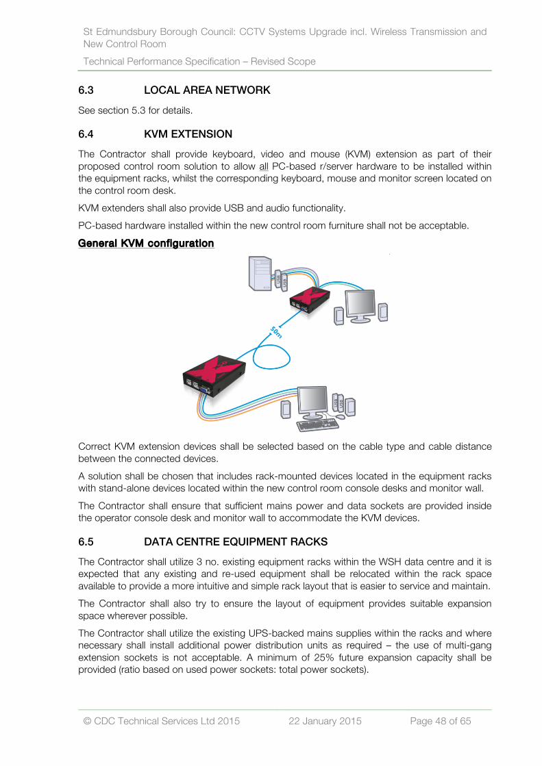
St Edmundsbury Borough Council: CCTV Systems Upgrade incl. Wireless Transmission and New Control Room Technical Performance Specification – Revised Scope
© CDC Technical Services Ltd 2015 22 January 2015 Page 48 of 65
6.3 LOCAL AREA NETWORK
See section 5.3 for details.
6.4 KVM EXTENSION
The Contractor shall provide keyboard, video and mouse (KVM) extension as part of their proposed control room solution to allow all PC-based r/server hardware to be installed within the equipment racks, whilst the corresponding keyboard, mouse and monitor screen located on the control room desk. KVM extenders shall also provide USB and audio functionality. PC-based hardware installed within the new control room furniture shall not be acceptable. General KVM conf igurat ion
Correct KVM extension devices shall be selected based on the cable type and cable distance between the connected devices. A solution shall be chosen that includes rack-mounted devices located in the equipment racks with stand-alone devices located within the new control room console desks and monitor wall. The Contractor shall ensure that sufficient mains power and data sockets are provided inside the operator console desk and monitor wall to accommodate the KVM devices.
6.5 DATA CENTRE EQUIPMENT RACKS
The Contractor shall utilize 3 no. existing equipment racks within the WSH data centre and it is expected that any existing and re-used equipment shall be relocated within the rack space available to provide a more intuitive and simple rack layout that is easier to service and maintain. The Contractor shall also try to ensure the layout of equipment provides suitable expansion space wherever possible. The Contractor shall utilize the existing UPS-backed mains supplies within the racks and where necessary shall install additional power distribution units as required – the use of multi-gang extension sockets is not acceptable. A minimum of 25% future expansion capacity shall be provided (ratio based on used power sockets: total power sockets).

St Edmundsbury Borough Council: CCTV Systems Upgrade incl. Wireless Transmission and New Control Room Technical Performance Specification – Revised Scope
© CDC Technical Services Ltd 2015 22 January 2015 Page 49 of 65
6.6 IT LAN & TELEPHONY
All internal LAN and telephony requirements shall be provided by the Employer as part of the ‘shell and core’ fit out. The Contractor shall liaise and coordinate with the Employer to ensure that sufficient notice is given to allow any cabling works to be undertaken following installation of technical furniture. The Contractor shall ensure that sufficient space is provided within the base of the furniture to allow the installation of the required number (TBC) of data sockets. The Employer contact for all IT/Telephony related issues is –
Employer Contact: Andrew Brindle T: 01284 757238 E: [email protected]
6.7 SHOPSAFE RADIO
ShopSafe radio forms an essential part of the CCTV monitoring service provided by SEBC and as such, has formed an important part of the design of the network as well as the layout of the technical furniture. The Contractor shall not be expected to undertake any works in relation to the ShopSafe radio system. Upgrades to the existing ShopSafe radio system is subject to a separate contract between the Employer and Radio Technology. However, the Contractor shall note that ONE of the desk monitors at EACH operator position shall be provided and installed by the Contractor for dedicated use by the ShopSafe radio system. Additionally, the Contractor shall provide dedicated KVM, USB and audio extension (as per section 6.4) between the ShopSafe radio server/PC (located in the equipment rack) and the operator console desk. The contact for all ShopSafe radio related issues is –
Contact: Phil Blenkhorn at Radio Technology T: 07971 950506 E: [email protected]
6.8 AIRWAVE RADIO
The Contractor shall not be expected to undertake any works in relation to the Airwave radio system. It is understood that the Airwave radios are stand-alone devices and can be easily relocated at a time to suit the progress of the project. The Contractor shall liaise and coordinate with the Norfolk and Suffolk Police Joint ICT Department to arrange the relocation of the Airwave radios.
Contact: David Woods, Airwave Support Manager T: 01473 613586 E: [email protected]

St Edmundsbury Borough Council: CCTV Systems Upgrade incl. Wireless Transmission and New Control Room Technical Performance Specification – Revised Scope
© CDC Technical Services Ltd 2015 22 January 2015 Page 50 of 65
DOCUMENTATION Section 7.7.1 GENERAL
At least two weeks prior to system handover, the Contractor shall submit draft copies of the Operations and Maintenance (O&M) manual and record drawings to the Employer (and/or Employer’s Representative) for approval. Any comments made by the Employer (and/or Employer’s Representative) shall be incorporated and the draft resubmitted. Once the draft documentation has been approved, formal copies shall be prepared. The draft copies of the documentation need not contain all the test certificates etc., but space shall be allocated within the manuals to receive them prior to the formal issue.
7.2 ASSET REGISTER
The Contractor shall produce a full asset register for all new equipment supplied and installed as part of the initial capital works project. The asset register shall be provided in a standard spread sheet format (i.e. *.csv or *.xls) and include detailed information relating to each item of equipment such as –
• Asset number (format to be provided by the Employer); • Description of equipment; • Type/make and model; • Serial number; • Version of software/firmware (where applicable); • Location of equipment at initial installation;
The Contractor shall include hard and soft copies within their submitted O&M documentation.
7.3 DESIGN DRAWINGS
The Contractor shall provide complete ‘as-built’ drawings in AutoCAD (.dwg) format, which shall include the following –
• Indicate all system device locations on a site-wide plan(s). No other system(s) shall be included on these plans;
• Include full schematic wiring information on these drawings for all devices. Wiring information shall include cable type, conductor routings, quantities, and connection details at device;
• Include a complete CCTV System one-line block diagram; • Include a statement of the system sequence of operation;
7.4 SYSTEM & PRODUCT DATA
The Contractor shall provide complete product data that includes the following –
• Manufacturer’s technical data for all material and equipment at the system and sub system level to be provided as part of the CCTV systems;
• System descriptions including analysis and calculations used in sizing the equipment required by the Employer;

St Edmundsbury Borough Council: CCTV Systems Upgrade incl. Wireless Transmission and New Control Room Technical Performance Specification – Revised Scope
© CDC Technical Services Ltd 2015 22 January 2015 Page 51 of 65
• The descriptions shall show how the equipment shall operate as a complete system solution to meet the performance requirements of the Employer. The following information shall be included (but not limited to) –
• Server(s) processor(s), disk space and memory size; • Description of site equipment and its individual configuration; • Network bandwidth, latency and reliability requirements; • Backup/archive system size and configuration; • Start up operations for each type of system; • System expansion capability and method of implementation; • System power requirements and UPS sizing; • Device / component environmental requirements (cooling and or heating parameters); • A description of the operating system and application software.
7.5 CONTRACT CLOSE OUT SUBMITTALS
The Contractor shall provide one (1) hard/paper copy and two (2) electronic copies of manuals including operating instructions, maintenance recommendations and parts list including wiring and connection diagrams modified to reflect as-built conditions.
7.6 MANUALS
The final copy of the manuals shall be delivered within 14 days after successful completion of the witness testing of all systems. Each manual shall have a table of contents and labelled sections and shall include, where applicable, the names, addresses and telephone numbers of the contractor responsible for the installation and maintenance of the system and the factory representatives for each item of equipment for each system. The final copy shall include all modifications made throughout the installation, commissioning and acceptance testing processes. The manuals shall contain the following sections – Funct ional Design The functional design section shall identify the operational requirements for the systems and explain the theory of operation, design philosophy and specific functions. A description of hardware and software functions, interfaces and requirements shall be included. Hardware The hardware section shall describe all equipment furnished including –
• General description and specifications; • Installation and check out procedures; • Equipment layout and electrical schematics to an appropriate level of detail; • System layout drawings and schematics; • Alignment and calibration procedures; • Manufacturers repair parts list indicating sources of supply.

St Edmundsbury Borough Council: CCTV Systems Upgrade incl. Wireless Transmission and New Control Room Technical Performance Specification – Revised Scope
© CDC Technical Services Ltd 2015 22 January 2015 Page 52 of 65
Software The software section shall describe the functions of all software and shall include all other information necessary to enable proper operation and where necessary, testing and troubleshooting. The section shall include (but not be limited to) –
• Definition of terms and functions; • System use and application software; • Initialization, start up, and shut down; • Reports generation; • Details on Client customization; • System checks and test;
Operat ion This section shall fully explain all procedures and instructions for the operation of the system including (but not be limited to) –
• Computers and peripherals; • System start up and shut down procedures; • Use of system, command, and applications software; • Recovery and restart procedures; • Graphical representation of system components and alarm presentation; • Assignment of control parameters to graphical components; • Generation of reports and audit trail; • General data entry; • Operator commands; • Alarm messages and reprinting formats; • System permissions functions and requirements.
Maintenance The maintenance section shall include descriptions of maintenance for all equipment including inspection, periodic preventive maintenance, fault diagnosis, and repair or replacement of defective components. The maintenance manual shall include a full list of parts for the systems provided. Passwords & Usernames All items of equipment that require log-on credentials to allow access to the configuration settings of said equipment, shall be identified and listed within the O&M manuals. All usernames and passwords for the individual items of equipment shall be provided. If necessary to avoid the disclosure of the Contractor’s own confidential passwords, the Contractor shall ask the Employer for a pre-determined username/password combination for use on all devices at the start of the contract.

St Edmundsbury Borough Council: CCTV Systems Upgrade incl. Wireless Transmission and New Control Room Technical Performance Specification – Revised Scope
© CDC Technical Services Ltd 2015 22 January 2015 Page 53 of 65
COMPLETION & HANDOVER Section 8.8.1 SITE WITNESS TESTING
When the installation is complete and fully tested and commissioned, the Contractor shall invite the Employer and/or Employer’s Representative to carry out an inspection of the installation. Any defects noted by the Employer and/or Employer’s Representative shall be corrected by the Contractor. (This does not preclude the Employer and/or Employer’s Representative making inspections and issuing defects reports at any time during the contract period.) When all the defects have been corrected to the Employer and/or Employer’s Representative’s satisfaction the Contractor shall issue a certificate confirming that all works are complete and that they comply with the specification and drawings for the project.
8.2 TRAINING
The Contractor shall provide a sufficient number of dedicated training sessions to the staff of the Employer including maintenance operatives and management where necessary. The Contractor shall be aware that the systems operators work on a shift basis and shall take account of this when organising dates for training sessions. The training provided shall be carried out by a competent person capable of communicating and presenting information in an easy to follow and methodical manner. The Contractor shall note that it may be necessary to undertake separate training sessions for each individual system to ensure ‘information overload’ does not occur. During the training course, the Contractor shall provide, where necessary, simple operating instructions to each attendee. These instructions shall be non-technical, use diagrams and pictures wherever possible and shall be written so that persons of all levels of intelligence can understand them. Once training is complete to the Employer’s satisfaction, the Contractor shall issue a certificate to the Employer and/or Employer’s Representative confirming what training has been provided and listing the names of the personnel who received it.
8.3 FINAL ACCEPTANCE / HANDOVER
Final acceptance and handover of the system(s) shall not be given until ALL of the following elements of the project have been carried out to the satisfaction of the Employer and/or Employer’s Representative –
• Satisfactory rectification of ALL items presented by the Employer and/or Employer’s Representative on a post installation / practical completion snagging / non-conformity report;
• Completion of all Employer training programmes; • Final project inspection; • Receipt, amendment if required and final approval of test, operating and maintenance
(O&M), health and safety and as-built documentation as per specification; • Satisfactory performance of the system for a two week period prior to Completion; • A signed defects liability certificate and if specified, a signed maintenance agreement; • Provision of a FULL SET of labelled security keys relating to ALL street furniture,
enclosures, cabinets and columns as well as any other lockable items that form part of the SEBC CCTV scheme;

St Edmundsbury Borough Council: CCTV Systems Upgrade incl. Wireless Transmission and New Control Room Technical Performance Specification – Revised Scope
© CDC Technical Services Ltd 2015 22 January 2015 Page 54 of 65
8.4 COMPLETION
The Employer and/or Employer’s Representative shall grant Completion of the project following satisfactory provision of items outlined above and when all other works as defined in the contract Works Information are complete. The Employer and/or Employer’s Representative shall be the deciding party as to when Completion shall be granted. The Contractor shall refer to the contract preliminaries for further information.
8.5 DEFECTS WARRANTY PERIOD
The Contractor shall include in their tendered sum a full 12-month defects liability and system warranty for every component of the new solution. This warranty shall include for the Contractor to attend site and repair, replace and fully restore to full working order all genuine system defects in line with the performance requirements of the service and maintenance provision outlined in the next section. Where any manufacturer offers a longer warranty on an item, the Employer shall expect to benefit from that also. (A list of warranties for individual parts shall be included within the documentation). The Contractor shall note that, irrespective of how much usage the Employer may already have had, the warranty period shall commence from the date of the Completion Certificate.

St Edmundsbury Borough Council: CCTV Systems Upgrade incl. Wireless Transmission and New Control Room Technical Performance Specification – Revised Scope
© CDC Technical Services Ltd 2015 22 January 2015 Page 55 of 65
SERVICE AND MAINTENANCE Section 9.9.1 GENERAL
The Contractor shall provide two (2) main elements of service and maintenance provision during the contract period as follows –
1. 24-hour engineer cover for reactive service calls and Planned Preventative Maintenance (PPM) during the initial 12-months defects period;
2. A further two-year service and maintenance cover, including 24-hour engineer cover for reactive service calls and PPM following completion of the defects period;
The total contract agreement for service and maintenance shall be for three (3) years following Completion of the project. The Contractor shall note that all ‘major’ items of hardware provided as part of the capital works project shall carry a 3-year warranty to align with the overall service and maintenance period and to assist with providing a reduced on-going maintenance cost. The service and maintenance provision shall include the following –
• Fully comprehensive service and maintenance cover to include all parts and labour costs associated with the rectification of a reported fault (or equipment fault identified during PPM) to a maximum equipment cost of £500 (excluding VAT). Labour costs shall include any plant/cherry picker hire necessary to assist with the repair;
• Fault classification for the service and maintenance agreement shall be – o EMERGENCY; o URGENT; o NON-URGENT.
• Details of the requirements for each classification are given in the next section. • Planned Preventative Maintenance (PPM) to be carried out at ALL sites and on ALL
equipment covered by this maintenance provision and is further detailed later in this section;
• Recommended Spares provision. The Contactor shall supply a list of recommended spare parts that shall be included as part of the service and maintenance agreement;
9.2 EQUIPMENT REPLACEMENT OR REPAIR COSTS
The fully comprehensive service and maintenance provision shall include for ALL equipment parts (or equipment repairs) to a maximum individual component/consumable cost of £500 (excluding VAT). The replacement (or repair) of any single component/consumable part that is less than this value, verbal or written authority from the Employer is NOT required. The Contractor shall be expected to outline the full details and reasoning for the replacement (or repair) of any single component/consumable part that is greater than £500 in cost, and a written quotation shall be submitted to the Employer for approval prior to undertaking the replacement/repair work.

St Edmundsbury Borough Council: CCTV Systems Upgrade incl. Wireless Transmission and New Control Room Technical Performance Specification – Revised Scope
© CDC Technical Services Ltd 2015 22 January 2015 Page 56 of 65
9.3 VANDALISM
Where an act of vandalism has been carried out to any installation, the Contractor shall carry out full repairs and commissioning to reinstate the installation to full working order wherever possible. The timescales for rectification of vandalised works shall be the same as those for none vandalised works detailed within item 10.3 of this document. Should the level of vandalism be such that this cannot be achieved, the Employer shall be informed and upon agreement an extension of time shall be issued. The Contractor is not expected to cover costs associated with vandalism as part of the maintenance provision.
9.4 PLANNED PREVENTATIVE MAINTENANCE (PPM)
The Contractor shall provide planned preventative maintenance (PPM) for all equipment at all sites covered by the maintenance contract. In general, all equipment at all sites shall be maintained to a high standard throughout the maintenance contract avoiding unnecessary breakdowns and callouts and the Contractor shall carry out full PPM and servicing of ALL equipment at each individual site at a maximum of six (6) monthly intervals. The works shall include performing all necessary visual and quality checks, cleaning, adjustments, calibration and set up procedures of all equipment covered by the maintenance contract. All PPM works shall be carried out to the manufacturer’s recommendations and the Contractor shall make themselves fully aware of all specific requirements and shall be aware that they may be requested to provide written evidence that the maintenance requirement of particular equipment has been investigated. All faults found during the PPM visits shall be repaired, adjusted or replaced as necessary. Should this not be possible during the PPM visit, then it shall be reported and logged as a service fault (as outlined in this document) and be completed within the timescales as per the classification of the fault given by the Employer. Any faults or damage found during the PPM visit that are not covered by the maintenance contract, such as vandalism or misuse, shall be immediately reported to the Employer to be investigated.
9.5 PPM SCHEDULE OF TASKS
The following schedule indicates the PPM maintenance tasks required but does not state how they shall be carried out. All maintenance activities shall be completed in accordance with the equipment manufacturer's guidelines, recommendations and good working practices.
• All cameras to be cleaned and adjusted as required; • The full operation of the camera in various light levels to be tested and voltage output
checks to each camera to be recorded as part of the PPM service record; • Camera wiper blades (where applicable) should be inspected, adjusted and replaced if
necessary; • All environmental/vandal proof housings should be inspected and secured where
necessary;

St Edmundsbury Borough Council: CCTV Systems Upgrade incl. Wireless Transmission and New Control Room Technical Performance Specification – Revised Scope
© CDC Technical Services Ltd 2015 22 January 2015 Page 57 of 65
• Camera housing gaskets/seals should be inspected for integrity to seal against water and/or dust where applicable and should be replaced where necessary to prevent further maintenance issues;
• Where applicable, lubrication of Pan & Tilt heads and other mechanical moving parts such as wiper arms shall be undertaken;
• All wireless transmission equipment shall be visually inspected and brackets/fixings checked for security and signs of corrosion;
• All cable/containment entry points should be inspected and secured where necessary; • All connections should be inspected, secured and made good where necessary; • All cabinets/door locks should be inspected, secured and lubricated where necessary
and adjusted to ensure correct operation;
9.6 EQUIPMENT COVERED IN PPM
The following list gives an indication as to the expected equipment to be covered under the maintenance contract –
• All cameras and lens assemblies; • All telemetry interfaces and control devices including Pan & Tilt motors, receiver boards
and any associated power supply units; • All transmission equipment (where not BT or Virgin Media responsibility) including all
wireless transmission; • All surge protection devices where installed; • All camera housings (regardless of type) and associated heaters and mounting brackets; • All wiper units and washer drive units and associated equipment (where applicable); • Camera mounting columns, brackets, conduits, protective covers, equipment
enclosures, street cabinets (except those provided by BT or Virgin Media) – incl. all locking devices;
• Fibre optic equipment (where not BT or Virgin Media); • All interconnecting cabling;
The Contractor shall also be aware of other obligations in relation to the CCTV systems as follows –
• The Contractor shall be responsible for identifying all faults associated with the BT or Virgin Media fibre optic video and control links associated with the public space CCTV system and for reporting to and liaison with these companies on behalf of the Employer to ensure that the system is restored to full operation as quickly as possible. The Contractor will not be responsible for the performance of BT or Virgin Media but shall inform the Employer of any response and performance issues of these companies – especially where Contractor KPI’s are likely to be effected;
• The Contractor shall be responsible for identifying all faults associated with the loss of the electrical mains supply to all equipment within the system and for reporting to and liaison with the electrical utility company, as appropriate, to ensure the system is restored to full operation as quickly as possible. The Contractor will not be responsible for the performance of the utility company but shall inform the Employer of any response and performance issues of these companies – especially where Contractor KPI’s are likely to be effected;
• The Contractor shall be responsible for providing the access vehicle and safety barriers and notices etc. for servicing the camera assemblies (i.e. camera, lens, housing and pan

St Edmundsbury Borough Council: CCTV Systems Upgrade incl. Wireless Transmission and New Control Room Technical Performance Specification – Revised Scope
© CDC Technical Services Ltd 2015 22 January 2015 Page 58 of 65
and tilt unit) in public areas. All tools, test equipment, spares, goods and materials in fulfilling the maintenance service shall be deemed to be included;
• The Contractor shall be responsible for touch up painting repairs to exterior surfaces of the externally mounted equipment as required. This includes camera posts and brackets, but excludes damage caused by vandalism. The Contractor shall allow for the this work as part of any PPM visit unless specifically requested by the Employer;
• In the event of the Contractor sending any part or equipment away from the installation for repair or overhaul, then all the costs, including those of packing, carriage and insurance, incurred in the dispatch, overhaul, repair, return and installation of the equipment shall be borne by the Contractor;
• The Contractor shall be responsible for providing all specialist tools and test equipment necessary to carry out the maintenance of the CCTV equipment and validate that the equipment is operating correctly to the optimum performance settings;
9.7 CONTROL ROOM EQUIPMENT AND EQUIPMENT RACKS
All control room equipment shall be checked and inspected against the manufacturer’s requirements and should include the following –
• Full inspection and test of CRMS system hardware and software to ensure optimum performance. Checks should include ALL necessary software license upgrades for any Windows OS, system drivers, anti-virus etc;
• Full inspection and test of digital recording hardware systems including any necessary software interrogation to ensure correct operation, hard drive rebuilding, software upgrades including license updates where applicable;
• Inspection and operation of all UPS back up devices (where applicable) – mains switch off should be performed and corresponding standby time recorded as part of service record;
• Alarm actions from UPS devices and other equipment within the remote hub/server room should be checked and verified and recorded as part of service records;
• Full inspection of ALL wireless transmission equipment including visual checks of bracketry, fixing points and cabling to ensure correct and reliable operation;
• Line-of-sight inspections for ALL wireless links should be checked and any potential issues that cannot be easily resolved (i.e. tree growth), alerted to the Employer for action;
• Full software interrogation of ALL network devices to ensure correct and most efficient operation;
• All equipment filters/fans should be inspected and cleaned or replaced where necessary;
• Electrical RCD/MCB units within the equipment racks should be checked for correct operation;
• All connections should be inspected, secured and made good where necessary;
9.8 SYSTEM BACK-UPS
The Contractor shall ensure that all control systems software configuration files are regularly backed-up to a separate storage device – i.e. USB memory stick, flash drive or USB hard drive. As a norm, the following shall apply –
• CRMS config files are backed-up on a weekly basis; • NVR config files are backed up on a weekly basis;

St Edmundsbury Borough Council: CCTV Systems Upgrade incl. Wireless Transmission and New Control Room Technical Performance Specification – Revised Scope
© CDC Technical Services Ltd 2015 22 January 2015 Page 59 of 65
• Wireless network configuration are backed-up on a monthly basis OR when alterations to the network are undertaken;
• Lists of IP address and other general network config information, shall be kept up to date;
9.9 OPERATOR & MAINTENANCE (O&M) INFORMATION
Where any equipment replacement results in the system O&M documentation being out of date, the Contractor shall update this documentation to the prior agreement and satisfaction of the Employer. Throughout the Contract Period the Contractor shall maintain full records of all attendances and repairs made under the contract and these changes should form part of the regular reporting process.
9.10 PPM PROGRAM OF WORKS
Upon Completion of the capital works contract, the Contractor shall submit to the Employer a FULL program of PPM visits detailing predicted dates for each maintenance visit. All PPM dates shall be agreed by the Employer and any special access arrangements shall be the responsibility of the Contractor. Should any date not be acceptable to the Employer, due to operational reasons, then a new date shall be agreed in order to carry out the PPM work within two weeks of the proposed date. All notifications described in the above shall form part of the regular reporting procedures as outlined in Section 10 and copies of all PPM reports shall be included with the normal monthly reports to the Employer. This procedure shall allow the progress of the PPM program to be closely monitored.
9.11 PPM SITE ATTENDANCE
In accordance with the PPM program of works, the Contractor shall ensure that PPM site attendance is equally spread throughout a 12-month PPM period to provide the Employer with the necessary technical on-site engineering resource to undertake the PPM work outlined in this section. This resource shall be for a minimum of ONE-DAY PER WEEK. The Contractor shall note that this resource may be in addition to any requirement for technical engineering resource to undertake logged service faults.
9.12 CONTRACT ADDITIONS/DELETIONS
The Contractor shall be aware that the Employer may amend the site equipment schedule at any time to accommodate changes in operational requirements, policy changes or other unrelated reasons that result in a change of the service provision. This may include, for example –
• Include changes to an existing remote site(s); • Adding or removing an individual CCTV camera or number of cameras; • Increase in 3rd party monitoring;

St Edmundsbury Borough Council: CCTV Systems Upgrade incl. Wireless Transmission and New Control Room Technical Performance Specification – Revised Scope
© CDC Technical Services Ltd 2015 22 January 2015 Page 60 of 65
The Employer shall give the Contractor a minimum of 7 days written notice of any changes to numbers of systems and the Contractor shall be responsible for the said changes, as part of this Contract, from the beginning of the month following the expiration of the written notice. The Employer shall not, without the written approval of the Contractor, reduce the value of the Contract (as a result of deletions) by a value of greater than 20% of the Contract price in any 12 months. Changes to the contract shall be costed by taking the existing maintenance cost of an identical or ‘most similar’ site to that which is being added or removed. The site to be used for the comparative costing shall be agreed by the Employer and the Contractor prior to the site being added or removed. Should there be a disagreement, an independent arbiter shall be consulted. I temised costs With the above in mind and given the complexities of this particular contract, as part of the Pricing Schedule the Contractor shall be expected to provide itemised service and maintenance costs for specific elements within the whole of the SEBC CCTV scheme. The itemised list shall include (but not limited to) –
• Service and maintenance (incl. PPM) cost for a new PTZ camera location c/w new transmission that is still within the warranty period;
• Service and maintenance (incl. PPM) cost for an ‘upgraded’ PTZ camera location that includes some equipment within the warranty period – for example, a camera location that has re-used existing camera equipment but has been connected to the new digital transmission network;
• Service and maintenance (incl. PPM) cost for a new STATIC camera location c/w new transmission that is still within the warranty period;
• Service and maintenance (incl. PPM) cost for an existing PTZ camera location using existing transmission that is not under any warranty – including cameras within the West Suffolk House, Forest Heath and Stowmarket CCTV schemes;
• Service and maintenance (incl. PPM) cost for an existing STATIC camera location using existing transmission that is not under any warranty – including cameras within the West Suffolk House, Forest Heath and Stowmarket CCTV schemes;
The Contractor shall be provided with the opportunity within the Pricing Schedule to outline and cost other combinations of new and/or existing equipment that are not listed above and that they feel would be appropriate to the contract.

St Edmundsbury Borough Council: CCTV Systems Upgrade incl. Wireless Transmission and New Control Room Technical Performance Specification – Revised Scope
© CDC Technical Services Ltd 2015 22 January 2015 Page 61 of 65
REPORTING & MONITORING Section 10.10.1 FAULT REPORTING
Throughout the contract period the Contractor shall establish and maintain an operational fault reporting centre to which all faults on the system shall be reported, the reporting centre shall be operational at all times during the hours of 8:30 am to 5:00 pm Monday to Friday excluding Bank Holidays. All calls to be answered within 30 seconds. Answering machines are not considered acceptable during the normal working day. At all other times faults shall be reported to a 24-hour reporting centre which is manned 24-hours per day, 365 days (366 days on a leap year) a year from where a call-out engineer will be contacted to attend to the reported fault. On site and repair times shall commence from the time of notification of a fault by the Employer to the Contractor or 24-hour Reporting Centre. On receipt of the instruction the Contractor or reporting centre will issue a job reference number. This job reference number shall relate specifically to the fault reported and shall be used to trace the job from start to finish. The Contractor shall maintain records of all work received, pending, completed, and all spare parts outstanding and shall provide a daily update to the Employer by email (if requested). The fault reporting procedures shall be subject to the prior approval by the Employer.
10.2 SERVICE RECORDS
The Contractor shall maintain proper and adequate service records, to a high standard, in respect of all aspects affecting the delivery of the maintenance service and progress of any new works and their completion. These records shall be regularly maintained within the CRMS (or other) so that the Employer can monitor the current state of outstanding calls/works. The records shall include (but not limited to) –
• Full contact details of all Contractor’s employees associated with the works or service; • Any access difficulties, e.g. the failure of the Contractor, the Employer (or building
tenant) to honour arrangements made for the execution of the works or service; • Any delays caused by the inadequacy of the order, specification or instruction; • Any delays caused by the failure to obtain specialist assistance or materials; • Any delay caused by Health and Safety matters, e.g. adverse weather or failure to
provide condition reports/risk assessments/method statements; • Any delay or cancellation caused by the Contractor’s withdrawal from site as a result of
actions, threats, comments or neglect on the part of tenants (or occupants) of the particular or adjoining property;
• Any details relating to all compensation claims, resolved or un-resolved;
In summary, any information that prevents the Contractor from delivering the service to the Employer shall be recorded to assist both parties when said issues are discussed at any monthly (or other mutually agreed timeframe) review/progress meeting.

St Edmundsbury Borough Council: CCTV Systems Upgrade incl. Wireless Transmission and New Control Room Technical Performance Specification – Revised Scope
© CDC Technical Services Ltd 2015 22 January 2015 Page 62 of 65
10.3 RESPONSE TIMES
It is expected that the Contractor shall categorise and prioritise faults and repairs to systems as Emergency, Urgent and Non-Urgent (or equivalent). The corresponding response shall be allocated at the time of the fault being reported by the Employer. EMERGENCY – Site attendance with in 4 hours. An Emergency fault shall be any fault that results in a major system failure. Examples are given as follows (but not limited to) –
• Network transmission failure, resulting in the loss of one or more remote sites; • CRMS system failure resulting in the loss of operation of cameras (incl. telemetry and
switching issues) or retrieval of recorded footage; • Loss of multiple display wall images; • CCTV system failure resulting in multiple CCTV cameras not being recorded per site;
ALL EMERGENCY repairs shal l be COMPLETED with in 24 hours from fault being reported **
** Exceptions to this ‘rule’ may exist and should be identified as such as part of any pre-contract agreement. URGENT – Site attendance with in 24 hours. An Urgent fault shall be any other fault not classified as an Emergency. An Urgent fault can be re-classified to an Emergency fault when, due to further problems or circumstances, the fault results in non-operation of a system. This re-classification shall be carried out by the reporting of a new fault, which will subsequently be given a new response time. Examples are given as follows (but not limited to) –
• Bad picture, loss of picture or image break-up to individual CCTV Camera(s); • Individual camera(s) not recording; • Reported UPS systems faults; • Minor faults to the control room equipment.
ALL URGENT repairs shal l be completed with in 3 working days from fault being reported.

St Edmundsbury Borough Council: CCTV Systems Upgrade incl. Wireless Transmission and New Control Room Technical Performance Specification – Revised Scope
© CDC Technical Services Ltd 2015 22 January 2015 Page 63 of 65
NON URGENT – Site attendance with in 3 working days. A Non Urgent fault shall be any other fault that cannot be classified as Urgent or Emergency. Examples of Non Urgent faults might include (but not limited to) –
• Minor faults on individual CCTV Cameras – i.e. wipers faults and camera preset problems;
ALL NON URGENT repairs shal l be completed with in 5 working days from appointment being made.
The Contractor shall note that the response times quoted are maximum target times and that all repairs are to be completed as quickly as practically possible before the target time has elapsed. The Contractor shall also note that the response times may be reviewed from time to time throughout the contract period and increased/decreased in agreement with both parties.
10.4 COMPLETION/SIGN-OFF OF WORKS.
The Contractor shall confirm all actions/repairs have been carried out with the control room staff and at the end each site attendance, shall report to the control room to sign-off all job sheets and record all completed works on the CRMS. Copies of all job sheets shall be left with control room staff (where applicable). Contractors shall be required to submit an engineer’s report for all work carried out or proposed and shall provide the following details as a minimum –
• Site address and contact name (if applicable); • Camera number/site/location; • Full details of work carried out; • Notifying the Employer of any details of chargeable work;
A completed repair shall be that point in time at which the system is returned to an acceptable level of operation to the satisfaction of the Employer and/or CCTV control room operators. Where a full repair has not been carried out, the Contractor shall use their best endeavours to restore the system to full operational status as quickly as possible; except where the fault is due to damage beyond the Contractor's reasonable control, at which point the Contractor is expected to take all necessary steps to expedite the repairs to the reasonable satisfaction of the Employer. If and when it becomes apparent to the Contractor that the work shall not be completed within the required response time specified for reasons beyond the control of the Contractor, then the Contractor shall inform the Employer of the reason(s) immediately on a verbal basis providing written confirmation within 24 hours (via email). The Employer, providing the reason(s) are acceptable shall make in writing such extension of time for completion as may be reasonable.

St Edmundsbury Borough Council: CCTV Systems Upgrade incl. Wireless Transmission and New Control Room Technical Performance Specification – Revised Scope
© CDC Technical Services Ltd 2015 22 January 2015 Page 64 of 65
10.5 DEFAULT IN PERFORMANCE
The default system is to provide an incentive to the Contractor to comply with the response times specified in the contract and to provide the Employer with a system for performance evaluation and, if applicable, provide grounds for termination of contract for excessive non compliance. A default notice shall be recorded by the Employer and issued to the Contractor for the following –
• Failure to respond to a call-out within the specified response timescales; • Repeated defaults will be issued for failure to respond to the same call-out every time
the timescale is exceeded; • Failure to resolve the problem within the specified resolution timescales; • Repeated defaults will be issued for failure to resolve the same problem every time the
timescale is exceeded; • Failure to carry out the preventative maintenance on each site to the agreed programme
without prior notice and agreement by the Employer; • False reporting of vandalism; • Failure to undertake the requirements for PPM works, including meeting agreed dates;
10.6 CONTRACTOR DEFAULT EXEMPTION
In exceptional circumstances the Contractor may claim exemption for a default or series of defaults for a specific problem by the issuing of a “default exemption claim”. This shall outline the exceptional circumstances of the delay and these shall be considered by the Employer. The Contractor shall be aware that awaiting repairs/parts or shortage of engineering staff shall not normally be considered as exceptional circumstances. In the event of a disagreement, an independent arbiter shall be consulted. The arbiter’s decision shall be final. The losing party shall pay any fees for the consultation. The independent arbiter shall be agreed between the Employer and the Contractor prior to commencement of Contract.
10.7 PERFORMANCE PENALTIES
The Employer and Contractor shall compile a record of the default notices. These shall be assessed on a monthly basis and the Employer shall make a deduction from the next monthly payment in accordance with the number of default notices issued. This deduction shall be included on the monthly invoice. The performance penalty system is a graded system such that the Employer shall be compensated for poor performance by a reduction in the monthly payment at the following rates –
• Less than 5 defaults in any 1 month: Nil • Between 5 and 10 defaults in any 1 month: 5% • Between 11 and 20 defaults in any 1 month: 15% • Between 21 and 30 defaults in any 1 month: 25% • Greater that 30 defaults in any 1 month: 50%

St Edmundsbury Borough Council: CCTV Systems Upgrade incl. Wireless Transmission and New Control Room Technical Performance Specification – Revised Scope
© CDC Technical Services Ltd 2015 22 January 2015 Page 65 of 65
The Contractor shall note that the above performance penalty percentages shall be subject to review throughout the contract period and may be changed in agreement between both parties.
10.8 TERMINATION
The default system shall provide grounds for termination of Contract under the following conditions.
• If the Contractor accumulates more than 20 defaults for 3 consecutive months; • If the Contractor incurs performance penalties for any consecutive 6-month period;
10.9 MONTHLY REPORTING
The Contractor shall produce monthly reports configured from the information gathered during the preventative maintenance, reporting, responding and resolution of faults as outlined in the contract. The reports shall include a minimum of the following information –
• Details of planned preventative maintenance (PPM) carried out; • List of every fault reported during the month with corresponding reference number; • Response times (average & maximum), i.e. time reported, arrival on site, leave site etc; • Number of Emergency, Urgent and Non Urgent faults; • Action taken on each visit; • Resolution times (average & maximum), if not on first visit; • All engineer job/time sheets; • No. of default notices issued; • List of faults for which defaults have been issued with full information; • Default exemption requests.
10.10 KPI REVIEW
The Employer and Contractor shall agree a series of Key Performance Indicators (KPIs) throughout the duration of the Contract. These shall initially be agreed and targets set at the pre-contract meeting and shall be reviewed at the monthly contract meetings. The monthly report, submitted at the monthly review meeting shall include commentary on each of the monitored areas highlighting the current position and an action plan on how to ensure continual improvements are made. End of Document