ccs model regulatory framework
TRANSCRIPT

2010
Carbon CaPTUrE and SToraGE
Model Regulatory Framework
November
INFORMATION PAPER

INTERNATIONAL ENERGY AGENCY
The International Energy Agency (IEA), an autonomous agency, was established in November 1974. Its mandate is two-fold: to promote energy security amongst its member countries through collective response to physical disruptions in oil supply and to advise member
countries on sound energy policy.
The IEA carries out a comprehensive programme of energy co-operation among 28 advanced economies, each of which is obliged to hold oil stocks equivalent to 90 days of its net imports. The Agency aims to:
n Secure member countries’ access to reliable and ample supplies of all forms of energy; in particular, through maintaining effective emergency response capabilities in case of oil supply disruptions.
n Promote sustainable energy policies that spur economic growth and environmental protection in a global context – particularly in terms of reducing greenhouse-gas emissions that contribute to climate change.
n Improve transparency of international markets through collection and analysis of energy data.
n Support global collaboration on energy technology to secure future energy supplies and mitigate their environmental impact, including through improved energy
efficiency and development and deployment of low-carbon technologies.
n Find solutions to global energy challenges through engagement and dialogue with non-member countries, industry,
international organisations and other stakeholders. IEA member countries:
Australia Austria
Belgium Canada
Czech RepublicDenmark
Finland France
GermanyGreece
HungaryIreland
ItalyJapan
Korea (Republic of)LuxembourgNetherlandsNew Zealand NorwayPolandPortugalSlovak RepublicSpainSwedenSwitzerland
TurkeyUnited Kingdom
United States
The European Commission also participates in
the work of the IEA.
Please note that this publication is subject to specific restrictions that limit its use and distribution.
The terms and conditions are available online at www.iea.org/about/copyright.asp
© OECD/IEA, 2010International Energy Agency
9 rue de la Fédération 75739 Paris Cedex 15, France
www.iea.org

2010
Carbon CaPTUrE and SToraGE
Model Regulatory Framework
November
Users of this publication should note that it is intended as a general overview of CCS regulation only. It is not intended to be exhaustive and does not constitute legal advice. Users should seek their own legal advice. The IEA makes no express or
implied warranties concerning any part of this publication, including no warranty of accuracy, completeness or fitness for a particular purpose. The IEA will not be held liable for loss or damage resulting from any inaccuracy, error or omission.
This publication does not necessarily reflect the views or policies of individual IEA Member countries.
INFORMATION PAPER


© OECD/IEA 2010 Carbon Capture and Storage Model Regulatory Framework
Page | 3
Foreword Energy-related carbon dioxide (CO2) emissions are set to double by 2050 unless decisive action is taken. International Energy Agency (IEA) analysis demonstrates, however, that it is possible – in the same timeframe to 2050 – to reduce projected greenhouse-gas emissions to half 2005 levels, but this will require an energy technology revolution, involving the aggressive deployment of a portfolio of low-carbon energy technologies.
The IEA has identified carbon capture and storage (CCS) as a crucial element of that portfolio of technologies, contributing around one-fifth of total emissions reductions required by 2050. CCS is also fundamental to least-cost carbon abatement strategies: without CCS, the overall cost of reaching the required emission reductions rises by 70%. To effectively contribute, however, the scale and urgency of CCS deployment is significant, with around 100 CCS projects required by 2020, and over 3 000 projects by 2050.
Such rapid expansion and scale-up of CCS technology raises a number of regulatory issues that must be addressed in parallel with ongoing efforts to demonstrate the technical, safety and environmental viability of industrial-scale CCS projects. The IEA Carbon Capture and Storage Model Regulatory Framework seeks to deal with this reality and assist governments to develop appropriate frameworks by drawing on CCS regulatory frameworks already in place in Australia, Europe the United States and elsewhere to propose key principles for addressing the broad range of regulatory issues associated with CCS.
Nobuo Tanaka IEA Executive Director

Carbon Capture and Storage Model Regulatory Framework © OECD/IEA 2010
Page | 4
Acknowledgements This publication was prepared by the International Energy Agency (IEA)’s Carbon Capture and Storage Unit. Brendan Beck was the lead IEA author for the publication, along with Justine Garrett, who provided significant input and support. Juho Lipponen, CCS Unit Head, provided overarching guidance and support. Many other IEA colleagues also made important contributions, in particular Tom Kerr and Nancy Turck.
In addition to the IEA staff, Paul Zakkour from Carbon Counts provided invaluable drafting support as a consultant to the project. A special thank you must also go to Ian Havercroft of University College London’s Carbon Capture Legal Programme and David Wagner from ReedSmith LLP, who were core to the development and drafting of the project and who both generously volunteered their time and effort.
This publication would also not have been possible without all of the comments and support received from the Advisory Committee that was established to guide the drafting process. The Advisory Committee included: Tim Dixon from the Implementing Agreement for a Co-operative Programme on Technologies Relating to Greenhouse Gases Derived from Fossil Fuel Use (IEA Greenhouse Gas R&D Programme), Paal Frisvold from the Bellona Foundation and then co-chair of the European Technology Platform for Zero Emission Fossil Fuel Power Plants’ task force on policy and regulation, Sarah Forbes from the World Resources Institute, Luke Warren from the Carbon Capture and Storage Association (CCSA), Ian Phillips from CO2DeepStore Limited and chair of the CCSA Regulatory Workgroup, Chris Short, Dale Seymour and Martin Burke from the Global CCS Institute, Ruth Hampton from the UK Department of Energy and Climate Change, Rosemary Whitbread from the UK Health and Safety Executive, Raphael Sauter from the European Commission, Robert Van Voorhees from the Carbon Sequestration Council, Kevin Bliss, formally of the Interstate Oil & Gas Compact Commission, Philip Marston from Marston Law, George Peridas from the Natural Resources Defense Council, Scott Anderson from Environmental Defense, Steve Tantala from the Australian Department of Resources, Energy and Tourism, Anna Beesley from the Victorian Government Department of Primary Industries, Marcelo Ketzer from the Brazilian Carbon Storage Research Center, Andrew Gilder from the IMBEWU Sustainability Legal Specialists, Ian Heyhow, formally of Natural Resources Canada, Sandra Locke from the Alberta Department of Energy, Gabriela von Goerne, advisor to the German Ministry of Environment, Annemarieke Grinwis from the Dutch Ministry of Economic Affairs, Iain Wright from BP, Tony Booer from Schlumberger, Sascha Ludge from Vattenfall, Arthur Lee from Chevron, Wolfgang Heidug, formally of Shell, Didier Bonijoly from BRGM and StraCO2, Robert Finley from the Illinois State Geological Survey, Michael Parker from ExxonMobil and Emily Fisher from the Edison Electric Institute. Thanks must also go to Mark De Figuerdo from the US Environmental Protection Agency, who was an observer to the development of the publication.
The IEA’s Marilyn Smith along with Tracy D’Afters, a consultant editor, helped to prepare the manuscript and provided technical editing. IEA’s Delphine Grandrieux and Anne Mayne provided helpful comments on layout and design.
This work was guided by the IEA Committee on Energy Research and Technology. Its members provided important review and comments that helped to improve the document.
For more information on this document, contact:
Brendan Beck, IEA Secretariat Tel. +33 (0)1 40 57 67 07 Email: [email protected]
Justine Garrett, IEA Secretariat Tel. +33 (0)1 40 57 67 97 Email: [email protected]
© OECD/IEA 2010 Carbon Capture and Storage Model Regulatory Framework
Page | 5
Table of Contents
Foreword ..................................................................................................................................... 3 Acknowledgements ......................................................................................................................... 4 List of figures .................................................................................................................................... 6 List of boxes ..................................................................................................................................... 6 List of examples ............................................................................................................................... 7 List of tables ..................................................................................................................................... 8 Executive summary .......................................................................................................................... 9 1 Introduction ................................................................................................................................ 13 1.1 The importance of carbon capture and storage (CCS) ...................................................... 13 1.2 The Model Framework ...................................................................................................... 15 2 Developing CCS regulatory frameworks .................................................................................... 22 2.1 Understanding the broader policy context ....................................................................... 22 2.2 Reviewing existing regulatory frameworks ....................................................................... 22 3 Broad regulatory issues .............................................................................................................. 22 3.1 Classifying CO2 ................................................................................................................... 25 3.2 Property rights ................................................................................................................... 26 3.3 Competition with other users and preferential rights issues ............................................ 29 3.4 Transboundary movement of CO2 ..................................................................................... 30 3.5 International laws for the protection of the marine environment ................................... 33 3.6 Providing incentives for CCS as part of climate change mitigation strategies .................. 35 4 Existing regulatory issues applied to CCS ................................................................................... 35 4.1 Protecting human health ................................................................................................... 39 4.2 Composition of the CO2 stream ......................................................................................... 40 4.3 The role of environmental impact assessment ................................................................. 42 4.4 Third-party access to storage site and transportation infrastructure ............................... 46 4.5 Engaging the public in decision making............................................................................. 48 5 CCS-specific regulatory issues (capture and transport) ............................................................. 51 5.1 CO2 capture........................................................................................................................ 51 5.2 CO2 transportation ............................................................................................................ 51 6 CCS-specific regulatory issues (storage) ..................................................................................... 51 6.1 Scope of framework and prohibitions ............................................................................... 55 6.2 Definitions and terminology applicable to CO2 storage regulations ................................. 56 6.3 Authorisation of storage site exploration activities .......................................................... 64 6.4 Regulating site selection and characterisation activities .................................................. 70 6.5 Authorisation of storage activities .................................................................................... 75 6.6 Project inspections ............................................................................................................ 80 6.7 Monitoring, reporting and verification requirements ....................................................... 82 6.8 Corrective measures and remediation measures ............................................................. 89 6.9 Liability during the project period ..................................................................................... 91 6.10 Authorisation for storage site closure ............................................................................... 94 6.11 Liability during the post-closure period .......................................................................... 100 6.12 Financial contributions to post-closure stewardship ...................................................... 105

Carbon Capture and Storage Model Regulatory Framework © OECD/IEA 2010
Page | 6
7 Emerging CCS regulatory issues ................................................................................................ 105 7.1 Sharing knowledge and experience through the demonstration phase ......................... 109 7.2 CCS ready ......................................................................................................................... 111 7.3 Using CCS for biomass-based sources ............................................................................. 112 7.4 Understanding enhanced hydrocarbon recovery with CCS ............................................ 114 Annex 1: Model Text .................................................................................................................... 116 Annex 2: References .................................................................................................................... 124 Acronyms and abbreviations ....................................................................................................... 126 Glossary ................................................................................................................................. 127
List of figures Figure 1: CCS deployment by region, 2010-50 ............................................................................... 13 Figure 2: The life cycle of a CCS project as adopted by this Model Framework ............................. 54 Figure 3: Components of the sub-surface that may be used in legal definitions ........................... 60 Figure 4: Storage site exploration period ....................................................................................... 65 Figure 5: Storage site operation and closure periods .................................................................... 75 Figure 6: Potential leakage routes and remediation techniques for CO2 injected into saline formations ...................................................................................................................................... 90 Figure 7: Storage site closure period .............................................................................................. 95 Figure 8: Example of how cased and uncased wells are abandoned today ................................... 97 Figure 9: Post-closure period ........................................................................................................ 101
List of boxes Box 1: IEA CCS regulatory work to date .......................................................................................... 15 Box 2: Key developments in CCS regulation to date ...................................................................... 21 Box 3: Key areas to review when developing CCS regulatory frameworks .................................... 23 Box 4: Frameworks for demonstration versus deployment ........................................................... 24 Box 5: EU experiences with CO2 classification ................................................................................ 26 Box 6: Knowledge-sharing requirements in the EC’s draft criteria for allocating the 300 million new entrant reserve of the EU ETS Directive ................................................................................. 28 Box 7: Reporting of cross-border CCS operations: the 2006 IPCC GLs approach ........................... 32 Box 8: Amendments made to London Convention, London Protocol and OSPAR Convention ..... 34 Box 9: CCS incentives under the EU ETS Directive.......................................................................... 36 Box 10: CCS incentives in the United States ................................................................................... 37 Box 11: Interaction of incentives and regulations in international policy ..................................... 38 Box 12: Australian federal approach to CCS occupational health and safety ................................ 39 Box 13: CO2 storage and public participation in the Netherlands: Barendrecht ............................ 49 Box 14: The need for flexibility in spatial boundary delineation .................................................... 61 Box 15: Post-closure monitoring requirements: the 2006 IPCC GLs view ...................................... 64 Box 16: CO2 storage site selection: the 2006 IPCC GLs view .......................................................... 71 Box 17: Data used to characterise and select geological CO2 storage sites: IPCC 2005 ................. 72 Box 18: Risk assessment requirements under international laws for protecting the marine environment ................................................................................................................................... 73 Box 19: Site-specific monitoring requirements: the 2006 IPCC GLs approach............................... 84 Box 20: Modelling, monitoring and recalibration: the 2006 IPCC GLs approach ........................... 87 Box 21: Reducing monitoring obligations: the 2006 IPCC GLs approach ....................................... 88 Box 22: Establishing a trust fund .................................................................................................. 106 Box 23: Essential requirements of a CCSR facility: IEA/CSLF report to the G8, 2010 ................... 111 Box 24: Negative emissions from biomass: the 2006 IPCC GLs approach.................................... 113

© OECD/IEA 2010 Carbon Capture and Storage Model Regulatory Framework
Page | 7
List of examples Example 1: Property rights: Greenhouse Gas Geological Sequestration Act 2008 (VIC), Victoria, Australia (Victoria GHG GS Act) ...................................................................................................... 27 Example 2: Interaction of CO2 storage with other resources: Victoria GHG GS Act ...................... 29 Example 3: Transboundary transport of CO2: London Protocol ..................................................... 33 Example 4: Allowable CO₂ stream: London Protocol ..................................................................... 42 Example 5: Effects assessment: OSPAR FRAM ............................................................................... 45 Example 6: Third-party access: EU CCS Directive ........................................................................... 47 Example 7: Public engagement: Geologic Storage of Carbon Dioxide (State of North Dakota, United States), SB 2095 (2009) ....................................................................................................... 49 Example 8: Public consultation plan: Victoria GHG GS Act ............................................................ 50 Example 9: Scope and prohibitions: EU CCS Directive ................................................................... 56 Example 10: Requirement to have a licence: Energy Act 2008 c. 32 (United Kingdom) ................ 66 Example 11: Components of an exploration authorisation application: IEA Model Framework ... 67 Example 12: An exploration permit: Victoria GHG GS Act ............................................................. 68 Example 13: Physical attributes of a suitable storage site: IEA Model Framework ....................... 73 Example 14: Prioritisation of storage authorisation: IEA Model Framework ................................. 78 Example 15: Requirements of a storage authorisation application: Act Relating to Carbon Sequestration (State of Wyoming, United States), HB 90 (2008) .................................................. 79 Example 16: Inspection of a storage site: EU CCS Directive ........................................................... 82 Example 17: Components of a monitoring plan: IEA Model Framework ....................................... 85 Example 18: Monitoring plan requirements: Victoria GHG GS Act ................................................ 86 Example 19: Measures in case of leakages or significant irregularities: EU CCS Directive ............ 90 Example 20: When remediation might be necessary: Greenhouse Gas Storage Act 2009 (QLD) (Queensland, Australia) .................................................................................................................. 93 Example 21: Closure obligations: Victoria GHG GS Act .................................................................. 98 Example 22: Closure obligations: Geologic Storage of Carbon Dioxide (State of North Dakota, United States), SB 2095 (2009) ..................................................................................................... 100 Example 23: Long-term liability: “Louisiana Geologic Sequestration of Carbon Dioxide Act” (State of Louisiana, United States) 30 Louisiana Revised Statutes 1101 (2009) ..................................... 103 Example 24: Long-term liability: Offshore Petroleum and Greenhouse Gas Storage Act 2006 (Commonwealth) (Australia) ........................................................................................................ 103 Example 25: Financial contribution for long-term costs: Victoria GHG GS Act ............................ 107 Example 26: Financial contribution for long-term costs: “Geologic Storage of Carbon Dioxide Act" (State of Oklahoma, United States), SB 1765 (2008) ............................................................ 108 Example 27: CCSR requirements: EU CCS Directive ..................................................................... 112 Example 28: CCSR requirements: Kusile Record of Decision ........................................................ 112 Example 29: CCS and Biomass: EU ETS monitoring and reporting guidelines .............................. 113 Example 30: Proposed Ownership of Pore Space (State of New York, United States), AO 5836 115 Example 31: Interaction of CCS and EHR legislation: Geologic Storage of Carbon Dioxide (State of North Dakota, United States), SB 2095 (2009) ............................................................................. 115
List of tables Table ES.1: Key issues relating to CCS regulatory frameworks ...................................................... 10 Table 1: Key issues relating to CCS regulatory frameworks by category ....................................... 17 Table 2: Advisory Committee for the Model Framework ............................................................... 18 Table 3: Documents reviewed ........................................................................................................ 19


© OECD/IEA 2010 Carbon Capture and Storage Model Regulatory Framework
Page | 9
Executive summary According to the International Energy Agency (IEA) publication Energy Technology Perspectives 2010 (ETP 2010), in the absence of new energy policies or supply constraints, energy-related carbon dioxide (CO2) emissions in 2050 will be twice 2007 levels. This is due primarily to increased fossil fuel demand and a rise in the carbon intensity of primary energy. The ETP 2010 BLUE Map Scenario provides a least-cost strategy for reducing projected 2050 greenhouse gas (GHG) emissions to half 2005 levels. This is vital for stabilising CO2 atmospheric concentration below 450 parts per million and limiting the long-term global mean temperature rise to 2.0oC to 2.4oC. The BLUE Map Scenario concludes that, in order to achieve the required emissions reductions in the most cost-effective manner, carbon capture and storage (CCS) will need to contribute around one-fifth of total reductions in emissions by 2050. Importantly, the BLUE Map results demonstrate that if CCS technologies are not deployed, the overall cost of reaching the necessary emissions reductions rises by 70%. CCS is therefore an essential part of the technology portfolio needed to achieve deep reductions in global emissions.
The 2009 IEA publication, Technology Roadmap: Carbon capture and storage (CCS Roadmap), highlights the need for an ambitious growth path for CCS facilities on the global scale. To enable the technology to meet the one-fifth contribution set out by ETP 2010, it will be necessary to deploy around 100 CCS projects by 2020, and over 3 000 projects by 2050. This will be an enormous technical, financial and logistical challenge, but it will also be a regulatory one.
This publication, the IEA Carbon Capture and Storage Model Regulatory Framework (Model Framework), seeks to deal with the reality that such rapid expansion and scale-up of CCS technology raises a number of regulatory issues that need to be addressed in parallel with ongoing efforts to demonstrate the technical, safety and environmental viability of industrial-scale CCS projects. Regulatory frameworks are required to ensure the effective stewardship of CO2 storage sites over the long term, the protection of public health and the environment, and the security of CCS activities. Appropriate regulatory frameworks are also required to clarify the rights and responsibilities of CCS stakeholders, including relevant authorities, operators and the public. Additionally, regulations are needed to underpin performance and associated incentive schemes, commercial transactions relating to CCS operations, and also to build public confidence in, and acceptance of, the technology.
The CCS Roadmap identifies three key actions for CCS regulatory development to support the needed level of deployment:
1. review and adapt existing legal frameworks to regulate CCS demonstration projects by 2011 in OECD countries, 2013 in early-mover non-OECD countries, and 2015 in all non-OECD countries with CCS potential;
2. all countries with CCS activities review existing legal frameworks for their ability to regulate CCS, identify barriers or gaps, and create a comprehensive CCS regulatory framework, if required, by 2020; and
3. address international legal issues, including development of an international monitoring and verification protocol for CO2 storage and allowance of transboundary CO2 transfer under the London Protocol by 2012.
The Model Framework supports the first two CCS Roadmap actions by providing a practical tool that governments can use to help develop their own national regulatory frameworks. In effect, by drawing on CCS regulatory frameworks already in place in Europe, Australia, the United States and elsewhere, the Model Framework harnesses the work of early-mover CCS regions for

Carbon Capture and Storage Model Regulatory Framework © OECD/IEA 2010
Page | 10
the benefit of countries at earlier stages in the regulatory development process. The Model Framework synthesises these existing frameworks to propose key principles for addressing the broad range of regulatory issues associated with CCS.
The Model Framework is structured to provide guidance to authorities around the world, operating in diverse legal and regulatory environments, and in the context of varying existing resource extraction or environmental impact frameworks. In this regard, it is necessarily high level and avoids prescribing how any particular issue should be translated into domestic legal systems. The Model Framework addresses 29 key issues identified as being critical to the regulation of CCS activities (Table ES.1).
Table ES.1: Key issues relating to CCS regulatory frameworks
1. Classifying CO₂ 11. Engaging the public in decision making
21. Corrective measures and remediation measures
2. Property rights 12. CO₂ capture 22. Liability during the project period
3. Competition with other users and preferential rights issue
13. CO₂ transportation 23. Authorisation for storage site closure
4. Transboundary movement of CO₂
14. Scope of framework and prohibitions
24. Liability during the post-closure period
5. International laws for the protection of the marine environment
15. Definitions and terminology applicable to CO₂ storage regulations
25. Financial contributions to post-closure stewardship
6. Providing incentives for CCS as part of climate change mitigation strategies
16. Authorisation of storage site exploration activities
26. Sharing knowledge and experience through the demonstration phase
7. Protecting human health 17. Regulating site selection and characterisation activities
27. CCS ready
8. Composition of the CO₂stream
18. Authorisation of storage activities
28. Using CCS for biomass-based sources
9. The role of environmental impact assessment
19. Project inspections 29. Understanding enhanced hydrocarbon recovery with CCS
10. Third-party access to storage site and transportation infrastructure
20. Monitoring, reporting and verification requirements
As shown in Table ES.1, the Model Framework addresses all stages of the CCS chain, including CO2 capture, transportation and storage. However, it focuses primarily on regulatory issues associated with CO2 storage, which is commonly accepted as presenting the most novel and complex challenges to CCS regulation. Regulatory issues associated with CO2 capture and transport are generally likely to fall within the scope of existing regulatory frameworks related to areas such as oil and gas, mining, waste, health and safety, property rights and transport, with little or no modification to those existing frameworks. Most of the CCS regulatory frameworks reviewed in drafting the Model Framework have a similar focus on regulating only CO2 storage.
For each issue listed above, the Model Framework provides a general description as well as more detailed explanatory material that sets out various considerations to be taken into account when designing relevant regulatory approaches. It also provides examples of how the issue has been addressed in existing CCS regulatory frameworks in various jurisdictions. A base

© OECD/IEA 2010 Carbon Capture and Storage Model Regulatory Framework
Page | 11
or “starting point” regulatory framework, referred to in the Model Framework as “Model Text” is also provided for CO2 storage issues, with the aim that countries can incorporate jurisdictionally appropriate additions and amendments as needed. This reflects the importance of CCS storage activities in the existing regulatory frameworks reviewed.
The Model Framework is directed toward countries that are currently developing or considering developing near-term regulatory approaches to facilitate CCS demonstration efforts, or need comprehensive regulatory frameworks for the large-scale deployment of CCS. In particular, countries that are understood to have strong potential for CCS deployment and developing countries are the principal target audience.


© OECD/IEA 2010 Carbon Capture and Storage Model Regulatory Framework
Page | 13
1. Introduction
1.1 The importance of carbon capture and storage (CCS) According to the International Energy Agency (IEA) publication Energy Technology Perspectives 2010 (ETP 2010), in the absence of new energy policies or supply constraints, energy-related carbon dioxide (CO2) emissions in 2050 will be twice 2007 levels. This is due primarily to increased fossil fuel demand and a rise in the carbon intensity of primary energy. The ETP 2010 BLUE Map Scenario provides a least-cost strategy for reducing projected 2050 greenhouse gas (GHG) emissions to half 2005 levels; this is vital for stabilising CO2 atmospheric concentration below 450 parts per million (ppm)1. It concludes that, in order to achieve the required emissions reductions in the most cost-effective manner, carbon capture and storage (CCS) will need to contribute around one-fifth of total reductions in emissions by 2050. Importantly, the BLUE Map results demonstrate that if CCS technologies are not deployed, the overall cost of reaching the required emissions reductions rises by 70%. CCS is therefore an essential part of the technology portfolio needed to achieve deep reductions in global emissions.
If CCS is going to reach the required level of deployment over the next 10 to 15 years and start to achieve the emissions reduction potential suggested by the ETP 2010 BLUE Map Scenario, it must move from its current research and demonstration phase with few commercial projects into a large-scale, commercial phase of technology deployment in all parts of the world (Figure 1).
Figure 1: CCS deployment by region, 2010-50
Source: IEA Technology Roadmap: Carbon capture and storage
1 This stabilisation target is broadly consistent with the goal set in the Copenhagen Accord to limit increase in global temperatures to
no more than 2oC. The Copenhagen Accord was developed by some of the world’s largest economies at the 15th Conference of the Parties to the United Nations Framework Convention on Climate Change in December 2009.

Carbon Capture and Storage Model Regulatory Framework © OECD/IEA 2010
Page | 14
1.1.1 Importance of regulating CCS activities and current status The projected level of expansion and scale-up of CCS technology raises a number of regulatory2 issues associated with, among other things, ensuring the protection of public health, safety and the environment, and the effective stewardship of CO2 storage sites over the long term. As such, efforts to demonstrate the technical, safety and environmental viability of commercial-scale CCS projects must be accompanied by parallel regulatory developments. This provides assurance that projects will proceed safely, and that CO2 stored will be permanently contained. The implementation of appropriate regulatory frameworks for CCS is also required to provide certainty regarding the rights and responsibilities of relevant stakeholders, including relevant authorities, operators and the public. Furthermore, regulations are required to: underpin performance and associated incentive schemes; support commercial transactions relating to CCS operations; and build public confidence in, and acceptance of, the technology.
Governments around the world have started to amend existing resource extraction or environmental impact frameworks to allow early CCS demonstration projects to move forward. Dedicated regulatory frameworks to facilitate the large-scale commercialisation of CCS over the longer term are simultaneously being developed in a number of countries and regions. For example, Directive 2009/31/EC of the European Parliament and of the Council of 23 April 2009 on the geological storage of carbon dioxide (EU CCS Directive) establishes a regulatory framework for the geological storage of CO2 within the European Union. Australia has enacted comprehensive state and federal CCS regulatory frameworks; the United States, Canada, Norway and Japan are also currently developing frameworks.
At the same time, the international community has amended a number of international legal instruments to advance CCS development. The 1996 Protocol to the Convention on the Prevention of Marine Pollution by Dumping of Wastes and Other Matter (London Protocol) was amended in 2006 to allow for offshore CO2 storage and again in 2009 to allow the cross-border transportation of CO2. In 2007, the Convention for the Protection of the Marine Environment of the North-East Atlantic (OSPAR Convention) adopted similar provisions.3 In 2006, the Intergovernmental Panel on Climate Change (IPCC) released revised Guidelines for National Greenhouse Gas Inventories (2006 IPCC GLs), which are used for calculating and reporting national GHG emissions and removals. Although not yet officially sanctioned for use, the 2006 IPCC GLs include a complete methodology for treating CCS under the Kyoto Protocol to the United Nations Framework Convention on Climate Change (UNFCCC), (Kyoto Protocol).4
Despite the progress underway in certain countries and at an international level, regulatory frameworks necessary to govern CCS effectively and support the technology’s deployment are not yet in place in the majority of countries around the world.
Given the importance of CCS regulation, the IEA has focussed on this area in undertaking its CCS work programme (Box 1). The most recent example is the 2009 IEA publication Technology Roadmap: Carbon capture and storage (CCS Roadmap),5 which outlines the required development
2 This IEA Carbon Capture and Storage Model Regulatory Framework adopts a broad interpretation of the term “regulate” or
“regulatory” to include any measures that a relevant authority has undertaken, or may undertake, to implement controls around CCS activities. This may include, for example, legislative action, regulatory action by way of subordinate legal instruments or any other regulatory measures to ensure legal compliance with relevant standards or requirements.
3 Note that the 2009 London Protocol amendment and the OSPAR amendments will enter into force when they have been accepted by the required number of parties.
4 Currently, Kyoto Protocol Annex 1 countries (industrialised) are obliged to use the 2006 IPCC GLs; non-Annex 1 countries (developing) do not have to meet this requirement.
5 Available at www.iea.org/Papers/2009/CCS_Roadmap.pdf.

© OECD/IEA 2010 Carbon Capture and Storage Model Regulatory Framework
Page | 15
and uptake of the technology needed to help stabilise atmospheric CO2 concentrations at 450 ppm. The CCS Roadmap identifies three key regulatory actions and milestones:
1. review and adapt existing legal frameworks to regulate CCS demonstration projects by 2011 in OECD6 countries, 2013 in early-mover non-OECD countries, and 2015 in all non-OECD countries with CCS potential.
2. all countries with CCS activities to review existing legal frameworks for their ability to regulate CCS, identify barriers or gaps, and create a comprehensive CCS regulatory framework, if required, by 2020.
3. address international legal issues, including development of an international monitoring and verification protocol for CO2 storage, and allowance of transboundary CO2 transfer under the London Protocol by 2012.
Box 1: IEA CCS regulatory work to date
1.2 The Model Framework
1.2.1 Purpose This Model Framework aims to support the first two actions for CCS regulatory framework development outlined in the CCS Roadmap, by guiding authorities seeking to develop CCS regulatory frameworks within their own jurisdictions. The Model Framework draws on existing regulatory frameworks for CCS to propose key principles (based on current approaches) for handling regulatory issues associated with CCS. The Model Framework consists of a proposed base regulatory framework (referred to as the Model Text) for regulating CCS activities, and accompanying explanatory materials and examples.
The Model Text aims to provide sample wording that is appropriate for relevant authorities to
6 Organisation for Economic Co-operation and Development.
This IEA Carbon Capture and Storage Model Regulatory Framework (Model Framework) sits within the context of broader IEA work on the regulatory aspects of CCS undertaken over the last decade, including more recently in the context of the IEA International CCS Regulatory Network. The network, created in 2008, provides a neutral forum for CCS regulators, policy makers and stakeholders to share updates and views on CCS regulatory developments, through annual meetings at the IEA in Paris and quarterly, web-based seminars on specific CCS regulatory issues. The network currently has a membership of over 1 300 people from 50 countries around the world, including 20 developing countries.
In response to a network recommendation, the IEA recently started to produce a review of worldwide developments in CCS regulatory activity. The IEA Carbon Capture and Storage Legal and Regulatory Review (Review), which will be produced every six months, is a compilation of two-page entries from national and regional governments, as well as key CCS organisations. The Review is intended to provide a forum for sharing knowledge on CCS legal and regulatory issues, help countries develop their own CCS regulatory frameworks, and identify steps taken towards the legal and regulatory goals in the CCS Roadmap. For each edition, the IEA also provides a brief analysis of key advances and trends. The first edition of the Review was released October 2010 and is available at www.iea.org/ccs/legal.
In addition to the CCS Roadmap, other IEA publications relating to CCS regulatory activity include: CO2 Capture and Storage: a Key Carbon Abatement Option (2008) and Legal Aspects of Storing CO2 (2005) and its update in 2007.

Carbon Capture and Storage Model Regulatory Framework © OECD/IEA 2010
Page | 16
apply in diverse legal and regulatory environments, as well as in the context of existing resource extraction or environmental impact frameworks. In this regard, the Model Text is necessarily high level; it avoids prescribing how any particular issue should be translated into a domestic legal system but instead provides a general “starting point” for a CCS regulatory framework, around which jurisdictionally appropriate additions and amendments can be incorporated. The explanatory discussion on each regulatory issue outlines key considerations that should be taken into account when adding such detail.
Given that regulating CCS activities is a new and evolving area, it is anticipated that approaches to the various issues identified in this Model Framework will also evolve. As such, the Model Framework is intended to be a living document, to be updated periodically as further experience in regulating CCS activities is gained. Jurisdictions developing regulatory frameworks for CCS are also likely to put in place review mechanisms to update regulatory approaches, incorporating any lessons learnt from early projects. This is particularly important given the challenges involved in establishing regulatory frameworks to underpin a technology that is developing at a rapid pace.
1.2.2 Scope This Model Framework addresses all stages of the CCS chain, including CO2 capture, transportation and geological storage. It focuses primarily, however, on the regulatory issues associated with CO2
storage, which are commonly accepted as presenting the most novel and complex challenges in elaborating regulatory frameworks for CCS. In most regions, existing regulatory frameworks are likely to address issues associated with the capture and transportation of CO2, or require only minor modifications to address these issues. Existing regulatory frameworks that may be relevant include those relating to: oil and gas; mining; waste; industrial permitting; health and safety; property rights; and transportation. The majority of the existing regulatory frameworks for CCS reviewed in drafting this Model Framework also seemed to focus on regulating only CO2 storage.
As the Model Text contained in this document has been developed through a process of review, synthesis and extraction of key principles from existing frameworks, it similarly focuses on CO2
storage. If a specific regulatory issue has not been addressed by the Model Text, explanatory materials are still provided, to assist relevant authorities in addressing these issues in an appropriate way. The structure of this Model Framework is described in further detail below.
1.2.3 Structure This Model Framework is structured around 29 key regulatory issues associated with CCS, which fall broadly into four categories:
• Broad regulatory issues: issues arising from the interaction of CCS regulatory frameworks with potentially pre-existing domestic or international laws.
• Existing regulatory issues applied to CCS: domestic regulatory issues that extend beyond CCS operations, which should be reflected in CCS regulatory frameworks.
• CCS-specific regulatory issues: issues that are specific to CCS and, in particular, to CO2 storage operations.
• Emerging CCS regulatory issues: issues that are unique to CCS and have been identified as being significant in regulating CCS activities, but that are still not well understood in a legal context or addressed in detail in existing CCS regulatory frameworks.
Depending on the category, relevant authorities are likely to take different approaches in addressing the legal issues associated with regulating CCS activities. Moreover, not all issues raised will necessarily be relevant to all jurisdictions. The key issues fall into each category as follows:

© OECD/IEA 2010 Carbon Capture and Storage Model Regulatory Framework
Page | 17
Table 1: Key issues relating to CCS regulatory frameworks by category
Bro
ad
regu
lato
ry
issu
es
1. Classifying CO2
2. Property rights
3. Competition with other users and preferential rights issue
4. Transboundary movement of CO2
5. International laws for the protection of the marine environment
6. Providing incentives for CCS as part of climate change mitigation strategies
Exis
ting
re
gula
tory
is
sues
appli
ed
to C
CS
7. Protecting human health
8. Composition of the CO2 stream
9. The role of environmental impact assessment
10. Third-party access to storage site and transportation infrastructure
11. Engaging the public in decision making
CC
S-sp
eci
fic
regu
lato
ry i
ssue
s
12. CO2 capture
13. CO2 transportation
14. Scope of framework and prohibitions
15. Definitions and terminology applicable to CO2 storage regulations
16. Authorisation of storage site exploration activities
17. Regulating site selection and characterisation activities
18. Authorisation of storage activities
19. Project inspections
20. Monitoring, reporting and verification requirements
21. Corrective measures and remediation measures
22. Liability during the project period
23. Authorisation for storage site closure
24. Liability during the post-closure period
25. Financial contributions to post-closure stewardship
Emerg
ing
CC
S re
gula
tory
is
sues
26. Sharing knowledge and experience through the demonstration phase
27. CCS ready
28. Using CCS for biomass-based sources
29. Understanding enhanced hydrocarbon recovery with CCS
The Model Framework includes a general description, more detailed explanatory material and examples from existing CCS regulatory frameworks on each of the key regulatory issues above. In relation to CCS-specific regulatory issues, Model Text is included, to provide national authorities with the building blocks of a base regulatory framework that can be considered when developing domestic CCS regulatory approaches on the issues raised.

Carbon Capture and Storage Model Regulatory Framework © OECD/IEA 2010
Page | 18
1.2.4 Target audience Given the purpose of this Model Framework (Section 1.2.1), the primary target audience for this document is countries that are currently developing, or considering developing, near-term regulatory approaches for CCS demonstration or comprehensive regulatory frameworks for large-scale commercial CCS deployment. This Model Framework is particularly aimed at large developing countries that have a good potential for CCS deployment. Certain countries and regions have advanced beyond the point where this document is likely to provide great assistance to their CCS regulatory development processes. It is these countries and regions whose work to date provides the foundation for this Model Framework. This document is not intended to bring into question regulatory approaches adopted in existing CCS regulatory frameworks.
1.2.5 Model Framework development process This Model Framework has been prepared under the supervision of an Advisory Committee made up of key CCS stakeholders, including various governments, industry bodies and non-governmental organisations. The Advisory Committee was assembled to include representatives from countries and regions that are well advanced in developing CCS regulatory approaches, as well as representatives from countries that may be interested in using the Model Framework to guide the development of their regulatory frameworks for CCS. Entities represented in the Advisory Committee are included in Table 2.
Table 2: Advisory Committee for the Model Framework7
IEA Greenhouse Gas R&D Programme8 Interstate Oil & Gas Compact Commission Natural Resources Canada
Global CCS Institute Illinois State Geological Survey Department of Energy, Alberta, Canada
The Bellona Foundation Marston Law Ministry of Environment, Germany
World Resources Institute Environmental Defense Ministry of Economic Affairs, Netherlands
The Carbon Capture and Storage Association
Natural Resources Defense Council Shell
Department of Energy and Climate Change, United Kingdom
Australian Government Department of Resources, Energy and Tourism, Australia
BP
Health and Safety Executive, United Kingdom
Brazilian Carbon Storage Research Center Chevron
European Commission Victorian Government Department of Primary Industries, Victoria, Australia
Vattenfall
Edison Electric Institute Support to Regulatory Activities for Carbon Capture and Storage (StraCO2)
ExxonMobil
Carbon Sequestration Council IMBEWU Sustainability Legal Specialists CO2DeepStore Limited
Schlumberger European Technology Platform for Zero Emission Fossil Fuel Power Plants BRGM
Note: the United States Environmental Protection Agency participated as an observer in the Model Framework development process.
To commence the Model Framework development process, Advisory Committee members were asked to identify documents, including existing and proposed legal instruments, regulatory guidelines and consultation documents, to be considered in preparing the Model Framework. A comprehensive list of documents reviewed is included in Table 3. These documents build on considerable previous work undertaken in the area of CCS regulation (Box 2). The Advisory
7 It should be noted that this Model Framework does not necessarily represent the views of Advisory Committee members. 8 Implementing Agreement for a Co-operative Programme on Technologies Relating to Greenhouse Gases Derived from Fossil Fuel Use.

© OECD/IEA 2010 Carbon Capture and Storage Model Regulatory Framework
Page | 19
Committee was also asked to identify key regulatory issues to be addressed in the Model Framework. The Model Framework drafting team then reviewed the documents in late January and February 2010, focusing on the key regulatory issues to be addressed in the Model Framework. The drafting team consisted of representatives from the IEA, University College London’s Carbon Capture Legal Programme, law firm Reed Smith LLP and the energy and climate change consultants, Carbon Counts. The Advisory Committee reviewed the Model Framework twice during the drafting process, with comments feeding back into subsequent drafts prior to publication. This Model Framework does not necessarily represent the views of Advisory Committee members.
Table 3: Documents reviewed9
Legal instruments:
Australia Barrow Island Act 2003 (WA), Western Australia, Australia. Greenhouse Gas Geological Sequestration Act 2008 (VIC), Victoria, Australia, and related regulations. Greenhouse Gas Storage Act 2009 (QLD), Queensland, Australia. Offshore Petroleum and Greenhouse Gas Storage Act 2006 (Cth), Australia, and related regulations.
Canada
Carbon Capture and Storage Funding Act, S.A. 2009, c. C-2.5, Alberta, Canada.
Europe
Council Directive 96/82/EC of 9 December 1996 on the control of major-accident hazards involving dangerous substances (Seveso II Directive), European Union. Directive 2003/87/EC of the European Parliament and of the Council of 13 October 2003 establishing a scheme for greenhouse gas emission allowance trading within the Community and amending Council Directive 96/61/EC of 24 September 1996 concerning integrated pollution prevention and control (EU ETS Directive), European Union. Directive 2009/31/EC of the European Parliament and of the Council of 23 April 2009 on the geological storage of carbon dioxide and amending Council Directive 85/337/EEC, European Parliament and Council Directives 2000/60/EC, 2001/80/EC, 2004/35/EC, 2006/12/EC, 2008/1/EC and Regulation (EC) No 1013/2006, European Union.
International and regional 1972 Convention on the Prevention of Marine Pollution by Dumping of Wastes and Other Matter (London Convention). 1992 Convention for the Protection of the Marine Environment of the North-East Atlantic (OSPAR Convention). 1996 Protocol to the Convention on the Prevention of Marine Pollution by Dumping of Wastes and Other Matter (London Protocol).
United Kingdom Energy Act 2008, United Kingdom.
United States
Act Regulating Carbon Sequestration (State of Montana, United States), Chapter 474, 2009 Montana Laws (2009). Act Relating to Carbon Sequestration (State of Wyoming, United States), HB 90 (2008). Act Relating to Certain Matters Regarding a Clean Coal Project (State of Texas, United States), SB 1461 (2007). Act Relating to the Development of Carbon Dioxide Capture and Sequestration (State of Texas, United States), HB 1796 (2009). Act Relating to the Establishment of Incentives for the Implementation of Certain Projects to Capture and Sequester Carbon Dioxide (State of Texas, United States), HB 469 (2009). Act Relating to the Implementation of Projects Involving the Capture, Injection, Sequestration, or Geologic Storage of CarbonDioxide (State of Texas, United States), SB 1387 (2009). Advanced Energy Tax Credits Act (State of New Mexico, United States), SB 994 (2007). “Carbon Dioxide Reduction Act” (State of Kansas, United States), HB 2419 (2007). Carbon Dioxide Sequestration (State of West Virginia, United States), West Virginia Code §§ 22-11A-1 to 22-11A-9 (2009). “Clean Coal FutureGen for Illinois Act” (State of Illinois, United States), 20 Illinois Compiled Statutes 1107 (2008). “Clean Coal Portfolio Standard Act” (State of Illinois, United States), Public Act 095-1027 (2009).
9 For up-to-date links to CCS legal and reference documents, see University College London Carbon Capture Legal Programme’s
website www.ucl.ac.uk/cclp/ccsabout.php or contact the IEA directly.
Carbon Capture and Storage Model Regulatory Framework © OECD/IEA 2010
Page | 20
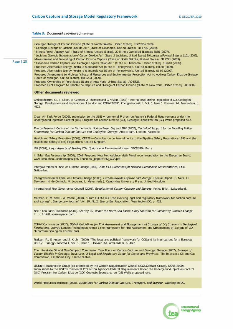
Table 3: Documents reviewed (continued)
Geologic Storage of Carbon Dioxide (State of North Dakota, United States), SB 2095 (2009). “Geologic Storage of Carbon Dioxide Act" (State of Oklahoma, United States), SB 1765 (2008). “Illinois Power Agency Act” (State of Illinois, United States), 20 Illinois Compiled Statutes 3855 (2007). “Louisiana Geologic Sequestration of Carbon Dioxide Act” (State of Louisiana, United States) 30 Louisiana Revised Statutes 1101 (2009). Measurement and Recording of Carbon Dioxide Capture (State of North Dakota, United States), SB 2221 (2009). “Oklahoma Carbon Capture and Geologic Sequestration Act” (State of Oklahoma, United States), SB 610 (2009). Proposed Alternative Energy Portfolio Standards Act (State of Pennsylvania, United States), HB 80 (2009). Proposed Alternative Energy Portfolio Standards Act (State of Pennsylvania, United States), SB 92 (2009). Proposed Amendment to Michigan’s Natural Resources and Environmental Protection Act to Address Carbon Dioxide Storage (State of Michigan, United States), HB 5253 (2009). Proposed Ownership of Pore Space (State of New York, United States), AO 5836. Proposed Pilot Program to Enable the Capture and Storage of Carbon Dioxide (State of New York, United States), AO 8802.
Other documents reviewed
Christophersen, O., T. Dixon, A. Greaves, J. Thomson and C. Vivian, (2009) “International Marine Regulation of CO2 Geological Storage. Developments and Implications of London and OSPAR 2009”, Energy Procedia 1, Vol. 1, Issue 1, Elsevier Ltd, Amsterdam, p. 4503.
Clean Air Task Force (2009), submission to the US Environmental Protection Agency’s Federal Requirements under the Underground Injection Control (UIC) Program for Carbon Dioxide (CO2) Geologic Sequestration (GS) Wells proposed rule.
Energy Research Centre of the Netherlands, Norton Rose, Gig and ERM (2007), Technical Support for an Enabling Policy Framework for Carbon Dioxide Capture and Geological Storage, Amsterdam, London, Katowice.
Health and Safety Executive (2009), CD228 — Consultation on Amendments to the Pipeline Safety Regulations 1996 and the Health and Safety (Fees) Regulations, United Kingdom.
IEA (2007), Legal Aspects of Storing CO2: Update and Recommendations, OECD/IEA, Paris.
In Salah Gas Partnership (2009), CDM: Proposed New Methodology Meth Panel recommendation to the Executive Board, www.insalahco2.com/images/pdf/Technical_papers/NM_CGS.pdf.
Intergovernmental Panel on Climate Change (2006), 2006 IPCC Guidelines for National Greenhouse Gas Inventories, IPCC, Switzerland.
Intergovernmental Panel on Climate Change (2005), Carbon Dioxide Capture and Storage, Special Report, B. Metz, O. Davidson, H. de Coninck, M. Loos and L. Meyer (eds.), Cambridge University Press, United Kingdom.
International Risk Governance Council (2008), Regulation of Carbon Capture and Storage, Policy Brief, Switzerland.
Marston, P. M. and P. A. Moore (2008), “From EOR to CCS: the evolving legal and regulatory framework for carbon capture and storage”, Energy Law Journal, Vol. 29, No.2, Energy Bar Association, Washington DC, p. 421.
North Sea Basin Taskforce (2007), Storing CO2 under the North Sea Basin: A Key Solution for Combating Climate Change, http://nsbtf.squarespace.com.
OSPAR Commission (2007), OSPAR Guidelines for Risk Assessment and Management of Storage of CO2 Streams in Geological Formations, OSPAR, London (including at Annex 1 the Framework for Risk Assessment and Management of Storage of CO2 Streams in Geological Formations).
Radgan, P., S. Kutter and J. Kruhl, (2009) “The legal and political framework for CCS and its implications for a European Utility”, Energy Procedia 1, Vol. 1, Issue 1, Elsevier Ltd, Amsterdam, p. 4601.
The Interstate Oil and Gas Compact Commission Task Force on Carbon Capture and Geologic Storage (2007), Storage of Carbon Dioxide in Geologic Structures: A Legal and Regulatory Guide for States and Provinces, The Interstate Oil and Gas Commission, Oklahoma City, United States.
US Multi-stakeholder Group (co-ordinated by the Carbon Sequestration Council's CCS Contact Group), (2008–2009), submissions to the US Environmental Protection Agency’s Federal Requirements Under the Underground Injection Control (UIC) Program for Carbon Dioxide (CO2) Geologic Sequestration (GS) Wells proposed rule.
World Resources Institute (2008), Guidelines for Carbon Dioxide Capture, Transport, and Storage, Washington DC.

© OECD/IEA 2010 Carbon Capture and Storage Model Regulatory Framework
Page | 21
Box 2: Key developments in CCS regulation to date
The documents reviewed for the purposes of developing the Model Framework draw from a far larger pool of CCS research and development internationally. For example, the Model Framework draws significantly on the EU CCS Directive, which built on the OSPAR CO2 storage amendments (Box 8) and 2007 Guidelines for Risk Assessment and Management of Storage of CO2 Streams in Geological Formations10 (created by 15 countries). The 1972 Convention on the Prevention of Marine Pollution by Dumping of Wastes and Other Matter (London Convention) CO2 storage amendments (Box 8), guidelines and risk assessment documents11 (to which 84 countries provided input), provided the starting point for the developments mentioned above.
All of these documents use the methodology for site assessment and monitoring provided by the 2006 IPCC GLs chapter on CCS (to which 194 countries provided input). The conclusions and recommendations in each document derive from specific work and reviews by international technical experts, including both environmental lawyers and storage geologists.
10 OSPAR Commission (2007), OSPAR Guidelines for Risk Assessment and Management of Storage of CO2 Streams in Geological
Formations, OSPAR, London (including at Annex 1 the Framework for Risk Assessment and Management of Storage of CO2 Streams in Geological Formations).
11 International Maritime Organization (2007), London Protocol: Specific Guidelines for Assessment of Carbon Dioxide Streams for Disposal into Sub-Seabed Geological Formations, www.imo.org/includes/blastDataOnly.asp/data_id%3D25527/9-CO2SequestrationEnglish.pdf; International Maritime Organization (2006), Risk Assessment and Management Framework for CO₂ Sequestration in Sub-Seabed Geological Structures, www.imo.org/includes/blastDataOnly.asp/data_id%3D19064/CO2SEQUESTRATIONRAMF2006.doc.
Carbon Capture and Storage Model Regulatory Framework © OECD/IEA 2010
Page | 22
2. Developing CCS regulatory frameworks
2.1 Understanding the broader policy context The broader policy context driving carbon capture and storage (CCS) deployment is likely to shape the development of CCS regulatory frameworks. For example, if a key incentive for CCS is to generate carbon dioxide (CO2) reduction credits as part of an international greenhouse gas reduction policy, this context will place specific requirements on CCS operations in relation to monitoring and verification.
Other policy objectives that may drive CCS include: the transition to low-carbon energy systems; maintaining economic competitiveness; job creation; and enhancing energy security by using domestic, or reliably imported, energy reserves.
Understanding the broader policy drivers behind CCS deployment should be the first step in developing CCS regulatory frameworks.
2.2 Reviewing existing regulatory frameworks A further issue to consider when preparing to develop CCS regulatory frameworks is the extent to which existing frameworks cover aspects of the CCS chain. The actions and milestones for CCS framework development in the CCS Roadmap recommend that existing regulatory frameworks be reviewed and adapted to regulate CCS demonstration projects before assessing whether comprehensive CCS regulatory frameworks for large-scale deployment are required. Consequently, it is important to understand the context in which CCS regulation will sit, including at a local, regional and national level. International laws and policy may also have an impact on domestic CCS regulations. A thorough review of existing regulatory frameworks and policy should therefore be undertaken before developing dedicated CCS regulatory frameworks.
It is important to consider the following four key issues when carrying out this review. First, how issues raised by CCS operations can potentially be regulated by modifying existing regulatory frameworks to cover certain aspects of the CCS chain (for example, existing industrial pollution control legislation or underground fluid injection laws). Second, whether existing regulatory frameworks pose potential barriers to various aspects of CCS (for example, groundwater protection legislation may prevent CO2 injection into saline formations). Third, whether a CCS regulatory regime could have any unintended consequences or interaction with existing laws (see, for example, the discussion regarding the exclusion of CCS activities from EU waste regulations [Box 5]). Forth, once the context is understood, any gaps in which aspects of the CCS chain are not addressed by existing laws can also be identified.
It is only once all gaps and barriers have been identified that it becomes clear whether existing frameworks should be amended or new frameworks developed to regulate CCS. This process is described in more detail in the steps below:
• International laws and policy: international laws and policy and the international obligations of jurisdictions can have an impact on the development of domestic CCS regulatory regimes. There may be certain obligations associated with international treaties or protocols that will need to be incorporated into any legal and regulatory framework for CCS. For example, international laws on environmental protection, such as those intending to protect the marine environment, may have implications for the geological storage of CO2 in the sub-seabed. International climate change commitments are also likely to be relevant. In the future, it is expected that international treaties and agreements will increasingly address CCS

© OECD/IEA 2010 Carbon Capture and Storage Model Regulatory Framework
Page | 23
activities. In addition, general obligations under international law, such as the duty to prevent transboundary harm, could affect domestic CCS activities. Jurisdictions should therefore address these obligations on a case-by-case basis.
• Existing national/regional context: at the domestic level, it is likely that jurisdictions will be required to review existing national regulatory frameworks governing, for example: energy production; environmental protection; land-use planning; property rights; water and groundwater protection; waste disposal activities; health and safety; and oil and gas exploration. (The sections of this Model Framework relevant to the key types of domestic regulatory frameworks for review are identified in Box 3).
Box 3: Key areas to review when developing CCS regulatory frameworks
Existing laws related to:
• Environmental impact assessments for major infrastructure projects (Section 4.3).
• Occupational health and safety; industrial accidents; industrial pollution; civil protection (e.g. in the context of liability and in the event of damages or harm caused by CO2 releases from capture, transport and injection facilities or leakage from CO2 storage sites) (Section 4.1); and planning procedures.
• Infrastructure decommissioning and oil field abandonment practices (Section 6.10).
• Pipeline developments; planning directives used to determine rights of way and corridors for pipelines (Sections 4.4 and 5.2); and operational terms and conditions.
• Waste management (Sections 4.2 and 5.1).
• Groundwater protection (Section 4.2).
• Oilfield operations (Section 7.4).
• Gap and barrier analysis: this stage involves comparing existing regulatory frameworks with what future regulation aims to achieve. Any difference between the two is defined as “a gap” and any conflicting regulation would be a “barrier”. The analysis then leads to specific actions that are needed to close this gap and/or remove any barriers. To perform the gap and barrier analysis, each framework should be reviewed and assessed to determine:
• the scope and coverage of the existing framework, in terms of whether CCS operations may fall within its scope;
• suitability to handle the specific risks involved in CCS operations and whether modifying the scope of the framework to cover CCS would help fill the regulatory gaps for CCS;
• whether specific derogations are required to remove any barriers to CCS;
• whether conferring requirements or removing barriers would create any unintended consequences for existing activities and operations; and
• potential conflicts and, if possible, which law will prevail (e.g. last in time rule or application of lex specialis – where a law governing a specific subject matter prevails over a general law).
• Revision of existing regulatory frameworks or dedicated framework: two possible approaches for developing a CCS regulatory framework include revising existing frameworks to cover CCS activities, or developing a dedicated CCS framework. This choice will be based on the potential that existing frameworks have to regulate CCS activities and how effective the resulting framework is expected to be. In some cases, amendments to existing frameworks will suffice in the short term to regulate CCS projects in the demonstration phase

Carbon Capture and Storage Model Regulatory Framework © OECD/IEA 2010
Page | 24
(Box 4). However, dedicated frameworks are likely to be necessary for larger-scale deployment. When developing CCS regulatory frameworks, it is useful to consult with relevant stakeholders throughout the various stages of the development process, including both the planning and post-implementation phases. It is also important to consider the regulatory approaches of other jurisdictions, as consistency among regions will create a level playing field for operators and help harmonise cross-border issues (Section 3.4). Governments may also need to weigh up the cost of proposed CCS regulatory measures with the benefits.
• Review: CCS technology is developing fast. Therefore, whichever approach is selected, review mechanisms may be useful for updating regulatory approaches and ensuring that they remain fit for purpose.
Box 4: Frameworks for demonstration versus deployment
It is important to bear in mind why a CCS regulatory framework is being developed when designing regulatory approaches for CCS. In effect, a framework designed to regulate CCS demonstration is likely to involve a small number of first-of-a-kind projects and may therefore differ significantly from a broader framework aimed at regulating large-scale commercial CCS deployment.
CCS is currently in a demonstration phase in most parts of the world, designed to test the efficacy of, and potential to scale-up, various aspects of the technology. This demonstration phase will also provide a testing ground for emerging regulatory frameworks for CCS, as well as public engagement programmes. During this phase, not all jurisdictions will necessarily need to develop comprehensive regulatory frameworks for full-scale commercial deployment, particularly in regions where only one or two projects are likely to be developed in the next 10 to 15 years. Comprehensive regulatory frameworks can take several years to develop. In order to accelerate demonstration projects during this phase, some jurisdictions may consider developing one-off or stand-alone requirements for individual projects.
These could, for example, take the form of: individual regulatory instruments that stipulate the terms of approval for specific projects; project specific authorisations that set out terms for managing a particular project; or agreements between the relevant authority and the operator, detailing the operator’s obligations regarding the demonstration project. The processes and requirements set out in this Model Framework are still likely to be relevant to such instruments. Regulatory instruments for the demonstration phase could also prove useful in testing regulatory approaches before moving towards comprehensive frameworks at the national level.

© OECD/IEA 2010 Carbon Capture and Storage Model Regulatory Framework
Page | 25
3. Broad regulatory issues The issues set out below arise from the interaction of carbon capture and storage (CCS) regulatory frameworks with potentially pre-existing domestic or international laws. These issues should be assessed for their relevance to a particular jurisdiction when establishing CCS regulatory frameworks.
3.1 Classifying CO2 One of the first issues to consider in designing regulatory frameworks for CCS is how carbon dioxide (CO2) is, or will be, classified under national and international laws. The legal classification of CO2 has major implications on the way existing regulatory frameworks might apply to CCS operations. This is because classifying CO2 or “captured CO2” as reflecting certain properties (e.g. as hazardous or polluting) or classifying the act of capturing, transporting and storing CO2 as similar to existing activities, such as waste management, may mean that aspects of existing regulations will apply to CCS operations. Thus, clearly defining how CO2 is or is not to be classified and/or what type of activity constitutes a CCS operation is the first step to ensuring effective regulation. The implications of classifying CO2 or CCS activities in a certain way are likely to differ across jurisdictions depending on existing regulatory frameworks. This issue may also be influenced by whether the CO2 is being injected as part of a commercial activity.
Classification issues to consider include:
• Hazardous: is or will a captured CO2 stream be classified as hazardous? CO2 cannot inherently be considered hazardous as all living organisms respire CO2. However, it may be determined that CO2 becomes hazardous depending on the presence of certain impurities, its pressure, concentration or the volumes at which it is being stored and handled (Section 4.2).
• Waste: is or will captured CO2 be classified as waste? The properties of CO2 may mean that it will be considered as waste matter under existing laws or that the act of injecting CO2 into geological formations will be considered as a waste disposal activity.
• Pollutant: is or will CO2 be classified as a pollutant or nuisance? Given the effects that CO2 emissions into the atmosphere can have on the earth’s climate, some jurisdictions may classify CO2 as a pollutant when emitted. This may have consequences under existing laws such as atmospheric protection laws, as well as for the potential efficacy of a CCS regulatory framework.
• Commodity: in some jurisdictions, such as the United States, CO2 is already treated as a commodity for use in enhanced hydrocarbon recovery (EHR) (Section 7.4) or in other industrial processes. Consequently, in such situations it may be a complex matter identifying where responsibility for regulating CO2 activities lies.
It is also possible that CO2 is, or will be, considered under a combination of the above classifications or that it has, or will have, a different classification in different situations.
As highlighted by the examples above, the way CO2 is classified may affect the way regulatory frameworks for CO2 are structured and how regulatory oversight is achieved and implemented. It is important to bear in mind that in addition to encouraging valuable economic activity, the ultimate aim of CCS regulatory frameworks is to ensure that CCS is conducted safely and securely and that human health and the environment are protected (Sections 4.1 and 4.3). To attempt to achieve this aim, a regulatory framework should create a chain of custody for CO2 from source to storage that allocates responsibilities and liabilities to regulators and operators alike. Consequently, practical approaches for achieving this should be pursued to ensure that

Carbon Capture and Storage Model Regulatory Framework © OECD/IEA 2010
Page | 26
regulatory frameworks avoid unintended consequences and do not create cumbersome administrative frameworks. An example of the latter point can be seen with existing waste regulatory frameworks, which may not be well suited to CCS operations as they tend to deal with batch transfers of waste between different operators, rather than continuous flows of material, as is the case in a CO2 pipeline. This means that in many instances, existing waste regulation frameworks may not be fit for purpose when applied to CO2 (Box 5).
Box 5: EU experiences with CO2 classification12
3.2 Property rights There are a number of property rights issues associated with CCS projects. These include:
• Ownership of the captured and stored CO2.
• Property rights linked to surface infrastructure and access to that infrastructure.
• Property rights relating to the sub-surface pore space in which injected CO2 is to be stored. This includes the rights of adjacent users in the event of leakage or unintended migration and the potential impact of injected CO2 on other minerals occupying the same pore space (e.g. oil, other hydrocarbons, etc.).
• Intellectual property rights relating to technology and know-how linked to capture, transportation, storage, sub-surface appraisal, sub-surface data, reservoir modelling and monitoring techniques and approaches.
CCS regulatory frameworks should recognise existing property interests and explain how property rights associated with stored CO2 are to be allocated and managed. It should be noted that different approaches are likely to be adopted depending on existing approaches to property rights in jurisdictions.
3.2.1 Ownership of captured and stored CO2 and property rights During the operational phase of a project, ownership of the captured CO2 should reside with the operator(s), based on establishing a chain of custody across the capture, transportation, injection and storage components of a project. This can be achieved through authorisation processes that allocate responsibility for CO2 during capture (based on existing industrial authorisation processes),
12 For further information, see Energy Research Centre of the Netherlands, Norton Rose, Gig and ERM (2007), Technical Support for
an Enabling Policy Framework for Carbon Dioxide Capture and Geological Storage, Amsterdam, London, Katowice, available at http://ec.europa.eu/environment/climat/ccs/pdf/policy_options_paper.pdf.
13 The EU Waste Regulation implements the European Union’s obligations under the 1989 Basel Convention on the Control of Transboundary Movements of Hazardous Wastes and their Disposal into EU law.
When the European Commission (EC) set about designing a regulatory framework for CCS, one of the key early questions posed was whether to classify captured CO2 as waste. The issue with this particular classification was that it would impose a raft of EU waste regulations onto CCS operations, including the requirement for waste transfer and receipt notifications to be maintained when there is a transfer of custody (e.g. between a capture facility and a transport facility) under Regulation (EC) No. 1013/2006 of the European Parliament and of the Council of 14 June 2006 on shipments of waste (EU Waste Regulation) and landfill regulations. While modifying these instruments to accommodate CCS was considered possible, it would have been difficult and may have resulted in a cumbersome regulatory framework with unintended consequences for other users of CO2. Consequently, the decision was made to exclude CO2 from the scope of EU waste regulations: see Articles 35 and 3613 of the EU CCS Directive.

© OECD/IEA 2010 Carbon Capture and Storage Model Regulatory Framework
Page | 27
transportation (Section 5.2), as well as injection and storage (Section 6.9). In the post-closure phase, ownership may revert to the state following any transfer of responsibility (Section 6.10). If this does occur, the host government will then bear responsibility for the stored CO2 (Section 6.11).
3.2.2 Surface infrastructure Property rights for surface facilities and related access will generally be allocated through existing property law and industrial permitting laws.
3.2.3 Ownership of sub-surface pore space In most jurisdictions in the world the sub-surface geology, such as the pore-space into which the CO2 is injected, is owned by the state. However, this is not the case in all jurisdictions. For example, in the United States, pore-space ownership is far less clear.14 In jurisdictions where the government owns the pore space, the government will be responsible for determining property access and allocation (Sections 6.3 and 6.5). Consideration will need to be given to which regulator has competence to regulate the particular issue of ownership. In the event of unintended migration or leakage affecting adjacent users, regulatory frameworks need to ensure that they protect other users by appropriately allocating responsibility (Sections 6.9 and 6.11).
Example 1: Property rights: Greenhouse Gas Geological Sequestration Act 2008 (VIC), Victoria, Australia (Victoria GHG GS Act)
3.2.4 Intellectual property rights As CCS is generally still in a research and demonstration phase, it may be advisable to consider using regulatory frameworks to set out rules for managing intellectual property rights (IPR). This may take the form of existing IPR laws that protect intellectual property or placing requirements on knowledge sharing, for example, mandating knowledge sharing to facilitate widespread and rapid deployment (Section 7.1). The latter could involve setting requirements for selective or public reporting of results of demonstration projects linked to the provision of public funding, based on the argument that private entities should not gain a competitive advantage from public spending.
Relevant to mandating knowledge sharing is the consideration that intellectual property owners may be reluctant to invest in developing new technologies in the absence of assurances that
14 For further information about pore-space ownership in the United States, see Duncan, I.J., S. Anderson and J.P. Nicot, (2009) “Pore-
space ownership issues for CO2 sequestration in the US”, Energy Procedia 1, Vol. 1, Issue 1, Elsevier Ltd, Amsterdam, p. 4427.
14 Underground geological storage formation is the property of the Crown
(1) The Crown owns all underground geological storage formations below the surface of any land in Victoria.
(2) Subsection (1) does not apply in relation to any land (other than Crown land) to the extent that the underground geological storage formation is within 15-24 metres of the surface of the land.
(3) Subsection (1) applies despite any prior alienation of Crown land.
(4) The Crown is not liable to pay any compensation in respect of a loss caused by the operation of this section.
15 Crown retains Crown land rights
In conferring any grant, lease, licence or other tenure of any Crown land after the commencement of this section on any person, the Crown retains all rights that it has in relation to any underground geological storage formation below the surface of that land, unless otherwise stated in the document by which the grant, lease, licence or other tenure is conferred.

Carbon Capture and Storage Model Regulatory Framework © OECD/IEA 2010
Page | 28
they have the possibility of making a return on their investment. This possibility may be reduced or lost if intellectual property owners have to transfer information into the public domain. Despite this potential challenge in implementing its financing packages for CCS, the European Union has drafted proposals for knowledge sharing associated with the disbursement of funds for CCS demonstration (Box 6). The European Union proposals draw heavily on the findings of the industry-led European Technology Platform for Zero Emission Fossil Fuel Power Plants (ZEP) (Section 7.1).
Box 6: Knowledge-sharing requirements in the EC’s draft criteria for allocating the 300 million new entrant reserve of the EU ETS Directive
The EU Directive 2003/87/EC establishing a scheme for greenhouse gas emissions allowance trading within the Community (EU ETS Directive), as amended by Directive 2009/29/EC amending Directive 2003/87/EC so as to improve and extend the greenhouse gas emission allowance trading scheme of the EU (EU ETS Amending Directive) provides that 300 million EU allowances (the tradable CO2 units of the EU Emissions Trading Scheme [EU ETS]) in the new entrant reserve of the EU ETS shall be monetised. The revenue is to be made available to help stimulate the construction and operation of up to eight commercial demonstration projects aimed at the environmentally safe storage of CO2 within the European Union.
On the basis of the revised EU ETS Directive, the EC has drafted a decision setting out criteria and measures for selecting projects, monetising the allowances and disbursing revenues. The decision also includes specific requirements for recipients with respect to knowledge sharing from projects, covering the following aspects:
A. Technical set-up and performance reliability CO2 captured performance at different levels, including differences between expected and real performance increase in fuel demand; electricity, heat and cooling demand key inputs and outputs and design future identified Research and Development issues
B. Cost level capital and operating costs total and cost per unit performance (ton CO2 stored, clean MWh produced)
C. Project management legislation/permitting stakeholder management, including interaction with Governments planning project organisation
D. Environmental impact effectiveness: reduction of CO2 emissions per unit of energy other environmental impacts at undisturbed operation
E. Health and safety incidents and near misses occurred (disturbed operation) monitoring and resolution systems to track safety health issues in undisturbed operation
F. CCS storage site performance models and simulations (development of CO2 plume — pressure front) history match results and adjustments (decision: normal within a deviation range or significant
irregularity that needs action) behaviour of displaced brine through CO2 injection.

© OECD/IEA 2010 Carbon Capture and Storage Model Regulatory Framework
Page | 29
3.3 Competition with other users and preferential rights issues As described in later sections of this Model Framework (Sections 6.3, 6.4 and 6.5), CO2 storage sites should be developed bearing in mind potential interactions with existing users and other existing or potential uses of the sub-surface. Issues to consider include:
• Co-existence of CO2 storage authorisations with existing authorisations relating to other uses of the sub-surface (e.g. oil and gas production, geothermal energy production, etc.).
• Preferential development rights issues for developers and issues relating to the potential to transfer existing sub-surface licences to a CO2 storage authorisation.
• Conflict resolution in the event that disputes arise in authorising sub-surface activities.
3.3.1 Co-existence of CO2 storage authorisations with existing authorisations It is important that regulatory frameworks are clear regarding how CCS operations can interact and co-exist with other permitted uses or users of the sub-surface. This is particularly important where CO2 is injected into formations that over- or underlie producing oil and gas horizons or those of geothermal use within the same block or within blocks adjacent to such formations. In such situations, consultations among relevant parties will be needed to assess the potential to co-exist, based on forward modelling of the behaviour of injected CO2. Decisions regarding the relative risk of a particular CO2 storage project to other users should be balanced against the importance of CCS in contributing to national and international reductions in greenhouse gas (GHG) emissions (Example 2).
3.3.2 Preferential rights When an operator has undertaken an extensive survey under a CO2 storage site exploration authorisation, then preferential rights should be given to that operator to apply for authorisation to develop the site and to store CO2 (Section 6.5). This type of preferential right should be subject to time limits to avoid the potential banking of storage rights, which could prevent new entrants into the market.
An additional consideration for preferential rights is how title and licensing procedures could account for an operator converting or supplementing an EHR project with a CO2 storage project (Section 7.4). In such cases, it will be important to balance the rights and knowledge held by the incumbent against ensuring free and open-market access to new entrants to ensure effective market functioning of CO2 storage operations. This issue is still emerging in regulatory discussions and further clarity on appropriate approaches will likely emerge through implementation over coming years.
Example 2: Interaction of CO2 storage with other resources: Victoria GHG GS Act
98 Contamination or sterilisation of a resource
(1) This section applies if, in the opinion of the Minister, the proposed injection and permanent storage of the greenhouse gas substance will present a significant risk of contaminating or sterilising other resources within the licence area but will not present a risk to public health or the environment.

Carbon Capture and Storage Model Regulatory Framework © OECD/IEA 2010
Page | 30
Example 2: Interaction of CO2 storage with other resources: Victoria GHG GS Act (continued)
(2) Despite Section 96(1)(b), the Minister may approve the plan if-
(a) the injection and monitoring licence holder has consent to undertake the work proposed in the plan from any holder of a resource authority in the licence area if the resource for which they hold an authority is likely to be contaminated or sterilised; or
(b) in the opinion of the Minister, approval of the plan is in the public interest.
99 Consent of other resource authority holders
An injection and monitoring licence holder who proposes to undertake work that will present a significant risk of contaminating or sterilising other resources in the licence area must take all reasonable steps to obtain consent to undertake that work from any holder of a resource authority in the licence area if the resource for which they hold an authority is likely to be contaminated or sterilised.
[…]
104 Compensation agreement (1) If the Minister has approved an injection and monitoring plan in accordance with section 96, the
injection and monitoring licence holder must not carry out any activity under an approved injection and monitoring plan unless-
(a) the licence holder has entered into a compensation agreement with the holder of a resource authority for a resource in the licence area that is likely to be contaminated or sterilised; or
(b) VCAT has determined the amount of compensation that is payable in relation to the proposed work to the holder of a resource authority for a resource in the licence area that is likely to be contaminated or sterilised.
(2) A person may only make an application to VCAT in respect of a claim after the expiry of any period of time specified for the purposes of this section by the regulations.
(3) A party who makes an application to VCAT is only entitled to have that claim determined by VCAT if VCAT is satisfied that the party has attempted to settle the claim by conciliation, but has not been able to do so because the other party has refused to negotiate a settlement or because both parties are unable to agree.
105 What compensation is payable for - resource authority holders
Compensation is payable by the holder of an injection and monitoring licence to any holder of a resource authority for any loss or damage that has been, or will be, sustained in relation to the land or resource as a direct, natural and reasonable consequence of carrying out any activity under the injection and monitoring plan including for-
(a) deprivation of access to the resource; and (b) loss of opportunity to recover or use the resource.
3.4 Transboundary movement of CO2 Transboundary issues can arise during the capture, transportation and storage of CO2, including under the following scenarios:
• Capture of CO2 in one jurisdiction and subsequent transportation across jurisdictional borders in pipelines, or other means of transportation, for storage in a different jurisdiction.
• Transit arrangements in which CO2 passes through a third jurisdiction to arrive at its final storage destination.
• Unintended migration or leakage of injected CO2 in the sub-surface across jurisdictional borders.
• Use of storage complexes that span jurisdictional borders.
• Secondary effects from storage activities occurring across jurisdictional borders (e.g. due to a sub-surface pressure front or displacement of sub-surface fluids across borders).
© OECD/IEA 2010 Carbon Capture and Storage Model Regulatory Framework
Page | 31
Transboundary regulatory co-operation will be necessary to create harmonised regulatory approaches to the issues outlined in later sections of this Model Framework. These include: exploration permit applications and authorisations; storage permit applications, authorisations and reviews; monitoring requirements; inspections; closure requirements; post-closure requirements; and the handling of long-term responsibility for the storage site and any associated liabilities. The co-ordination of regulatory oversight for authorisations, monitoring and reporting of projects in which transboundary issues can occur should also be addressed. There may be a need either to select a competent authority for one jurisdiction to oversee the project or, more likely, to implement joint regulatory responsibility for operations. A third element to consider is whether fiscal and market regulations for CCS operations need to be harmonised to avoid unintended outcomes. This harmonisation can include:
• Network facilitation/optimisation: co-ordinating interested parties across the CCS chain in order to optimise CO2 transportation and storage networks in a given region (e.g. the North Sea Basin). This could involve co-ordinating interested jurisdictions on, for example, joint bidding rounds for storage space exploration and market-based approaches to financing new pipeline capacity such as joint auctioning of pipeline capacity. Co-ordinating pipeline corridors and respecting important offshore areas in the continental shelf of the relevant jurisdictions are also important environmental considerations associated with CCS storage activities.
• Market liberalisation: deciding whether jurisdictions within a region should co-operate to ensure open access to networks and pore space for market entrants. This is especially relevant in the situation in which CO2 sources are located in a jurisdiction other than that in which CO2 storage is planned. In some cases, certain regions may have significant CO2 emissions and limited storage capacity and vice versa (e.g. Germany and Norway respectively). In such cases, co-operation will be paramount to enable a level playing field for CCS to develop.
• Property rights: dealing with sub-surface property rights issues in the event that CO2 unexpectedly migrates across jurisdictional boundaries post-injection. It is important to consider the types of government-to-government agreements that could be put in place to ensure that such incidences are effectively dealt with (Box 7).
• Fees: co-ordinating any fees charged for CCS activities such as exploration authorisation fees and levies for using sub-surface storage pore space. This would provide certainty for operators and avoid conflicting efforts to try to attract investment. It could also help to avoid any disputes regarding rental fees for pore space in the event of unintended CO2 migration across borders.
• Liability: determining whether there is a need to address liability for any CO2 emissions from sub-sea pipelines/networks and/or storage sites serving common areas if they fall under government stewardship. It is also important to consider how to allocate liability between storage sites, especially if, for example, responsibility allocation differs between areas. Establishing principles on how emissions would be monitored and reported in national inventories in cases in which jurisdiction is uncertain will also be an important consideration.

Carbon Capture and Storage Model Regulatory Framework © OECD/IEA 2010
Page | 32
3.4.1 GHG inventories and transboundary reporting The transboundary movement of CO2 also needs to be addressed when compiling GHG inventories. The 2006 IPCC GLs offer guidance in this context (Box 7).
Box 7: Reporting of cross-border CCS operations: the 2006 IPCC GLs approach15
3.4.2 Transboundary movement and International Law Transboundary movements of CO2 may trigger the application of international legal instruments, such as:
• The 1989 Basel Convention on the Control of Transboundary Movements of Hazardous Wastes and their Disposal (Basel Convention).
• The 1991 Bamako Convention on the Ban on the Import into Africa and the Control of Transboundary Movement and Management of Hazardous Wastes within Africa (Bamako Convention).
• The London Convention and London Protocol.
The Basel Convention and the “Basel Ban Amendment”16 prohibit the transfer of hazardous waste between mainly OECD and non-OECD countries. Similar provisions are included in the Bamako Convention to prevent hazardous waste being imported into Africa. Both instruments impose strict requirements relating to prior notice, consent and tracking of waste movements across international borders (Example 3). CCS has yet to be discussed under either the Basel Convention or the Bamako Convention. Such discussions will be contingent on decisions around CO2 classification and whether it is considered to be hazardous waste (Sections 3.1 and 4.2).
Article 6 of the London Protocol (Section 3.5) prevents the export of wastes or other matter for
15 2006 IPCC GLs, Vol. 2, Ch. 5, p. 5.20. 16 At the Second Meeting of the Conference of the Parties in 1994, the parties to the Basel Convention banned the transportation of
hazardous waste for final disposal from developed to developing countries (Decision II/12). In 1995, this ban was transposed into an amendment to the Basel Convention (Decision III/1), applicable to the transportation of hazardous waste between Annex VII countries (EU member states, OECD member states and Liechtenstein) and non-Annex VII countries.
CO2 may be captured in one country, Country A, and exported for storage in a different country, Country B. Under this scenario, Country A should report the amount of CO2 captured, any emissions from transport and/or temporary storage that takes place in Country A, and the amount of CO2 exported to Country B. Country B should report the amount of CO2 imported, any emissions from transport and/or temporary storage (that takes part in Country B), and any emissions from injection and geological storage sites.
If CO2 is injected in one country, Country A, and travels from the storage site and leaks in a different country, Country B, Country A is responsible for reporting the emissions from the geological storage site. If such leakage is anticipated based on site characterization and modelling, Country A should make an arrangement with Country B to ensure that appropriate standards for long-term storage and monitoring and/or estimation of emissions are applied (relevant regulatory bodies may have existing arrangements to address cross-border issues with regard to groundwater protection and/or oil and gas recovery).
If more than one country utilizes a common storage site, the country where the geological storage takes place is responsible for reporting emissions from that site. If the emissions occur outside of that country, they are still responsible for reporting those emissions as described above. In the case where a storage site occurs in more than one country, the countries concerned should make an arrangement whereby each reports an agreed fraction of the total emissions.

© OECD/IEA 2010 Carbon Capture and Storage Model Regulatory Framework
Page | 33
the purposes of dumping at sea or in the sub-seabed. As it stands, the article prohibits the transboundary movement of CO2 for contracting parties. Amendments have been made but are awaiting ratification, as described further below (Section 3.5).
If in the early stages of CCS project development it is clear that transboundary issues may arise, neighbouring regulators should exchange ideas on approaches for implementing CCS regulation. In practice, responses to transboundary issues are likely to evolve based on lessons learnt from specific projects. If neighbouring jurisdictions do not collaborate on transboundary issues, projects may need to be modified or abandoned.
Example 3: Transboundary transport of CO2: London Protocol
3.5 International laws for the protection of the marine environment
Two key international treaties relating to protection of the marine environment have been amended17 to remove barriers that restrict the storage of CO2 in sub-seabed geological formations. They are:
• The London Convention and London Protocol.
• The OSPAR Convention.
There are currently 86 contracting parties to the London Convention, 37 of which have signed the more rigorous London Protocol.18 The OSPAR Convention currently has 15 parties plus the EC.19 At the time these instruments were drafted, neither anticipated the emergence of CCS. However, prohibitions on the injection of matter into the sub-seabed in the respective instruments potentially extended to constrain CCS activities. Consequently, both instruments have been amended to allow for CO2 storage in sub-seabed geological formations, subject to certain conditions (Box 8). As described above, the London Protocol also prevents the transboundary movement of CO2 for the purposes of CO2 storage. An amendment has been proposed to address this restriction, but requires ratification by two-thirds of all contracting parties.
Both instruments prevent the storage of CO2 in the water column or on the seabed.
Parties to either or both instruments must ensure that regulatory frameworks developed for CO2 storage reflect the obligations imposed under these conventions as outlined in Box 8.
For the purpose of adopting good practice, non-signatory parties may also wish to consider including similar provisions in regulatory frameworks. This can help build a globally consistent set of CCS regulatory frameworks.
17 Certain amendments are yet to enter into force. 18 The list of signatory countries is available at: www.imo.org/home.asp?topic_id=1488. 19 Further information is available at: www.ospar.org/.
Article 6
Export of wastes or other matter
Contracting Parties shall not allow the export of wastes or other matter to other countries for dumping or incineration at sea.

Carbon Capture and Storage Model Regulatory Framework © OECD/IEA 2010
Page | 34
Box 8: Amendments made to London Convention, London Protocol and OSPAR Convention
20 International Maritime Organization (2007), London Protocol: Specific Guidelines for Assessment of Carbon Dioxide Streams for
Disposal into Sub-Seabed Geological Formations, www.imo.org/includes/blastDataOnly.asp/data_id%3D25527/9-CO2SequestrationEnglish.pdf.
21 OSPAR Commission (2007), OSPAR Guidelines for Risk Assessment and Management of Storage of CO2 Streams in Geological Formations, OSPAR, London.
Annex I of the London Protocol lists wastes and other matter that may be considered for dumping at sea or below the seabed, subject to a permitting procedure that takes account of the provisions of Annex II, which outlines generalised waste assessment guidelines. A proposed amendment to Annex I was agreed by parties in 2006 and came into force on 10 February 2007. The amendment adds “Carbon dioxide streams from carbon dioxide capture processes for sequestration” to Annex I of the London Protocol. This means that CO2 storage in sub-seabed geological formations is now allowed. The provisions are subject to the following requirements:
4 Carbon dioxide streams […] may only be considered for dumping, if:
.1 disposal is into a sub-seabed geological formation; and
.2 they consist overwhelmingly of carbon dioxide. They may contain incidental associated substances derived from the source material and the capture and sequestration processes used; and .3 no wastes or other matter are added for the purpose of disposing of those wastes or other matter.
Additional guidance on waste assessment in the context of CO2 streams was adopted in the form of the Specific Guidelines for Assessment of Carbon Dioxide Streams for Disposal into sub-Seabed Geological Formations in November 2007.20 These provide further clarification on streams acceptable for CO2 storage in sub-seabed formations:
1.3 For the purpose of these Guidelines, the following categories of substances are distinguished:
.1 the CO2 stream, consisting of: .1 CO2; .2 incidental associated substances derived from the source material and the capture and
sequestration processes used:
.1 source- and process-derived substances; and .2 added substances (i.e. substances added to the CO2 stream to enable or improve the
capture and sequestration processes); and .2 substances mobilized as a result of the disposal of the CO2 stream.
Under the OSPAR Convention, similar provisions to the London Convention and London Protocol were interpreted to prevent the storage of CO2 derived from certain sources/emplacement methods in the sub-seabed. With this in mind, a technical working group set about assessing conditions under which CO2 storage might be allowable under OSPAR. The result of various discussions was the OSPAR Framework for Risk Assessment and Management of Storage of CO2 Streams in Geological Formations (FRAM)21 document (Example 5), which sets out a framework for assessing the risks posed by a CO2 storage project for the marine environment. Subsequently, both Annex II (Prevention and elimination of pollution by land-based sources) and Annex III (Prevention and elimination of pollution from offshore sources) were amended.
Annex II now allows for an exception for:
[…]
2. (f) carbon dioxide streams from carbon dioxide capture processes for storage, provided:
i. disposal is into a sub-soil geological formation; ii. the streams consist overwhelmingly of carbon dioxide. They may contain incidental associated
substances derived from the source material and the capture, transport and storage processes used;
iii. no wastes or other matter are added for the purpose of disposing of those wastes or other matter;
iv. they are intended to be retained in these formations permanently and will not lead to significant adverse consequences for the marine environment, human health and other legitimate uses of the maritime area.

© OECD/IEA 2010 Carbon Capture and Storage Model Regulatory Framework
Page | 35
Box 8: Amendments made to London Convention, London Protocol and OSPAR Convention (continued)
3.6 Providing incentives for CCS as part of climate change mitigation strategies With the exception of using CO2 for EHR or where CO2 storage is a co-benefit of injecting other materials for the purpose of disposal (e.g. acid-gas injection with incidental CO2 storage), the purpose for undertaking CCS will primarily be climate change mitigation. The deployment of CCS is therefore a public good. At the same time, deploying the technology is likely to represent an additional cost to businesses. Consequently, there is a need to provide incentives or mandate operators to engage in CCS to promote CCS deployment and reduce GHG emissions.
Although the provision of incentives for CCS operations is critical to CCS deployment, it is unlikely that these incentives will be located within CCS regulatory frameworks. It is more likely that incentives will be included in parallel frameworks that address CO2 mitigation in general, rather than CCS specifically. This section provides an overview of the types of incentive
22 OSPAR Commission (2007), OSPAR Decision 2007/2 on the Storage of Carbon Dioxide Streams in Geological Formations,
www.ospar.org/v_measures/browse.asp?preset=1&menu=00510416000000_000000_000000&v0_0=&v1_0=title%2Creferencenumber%2Cdateofadoption&v2_0=&v0_1=OSPAR+Decision+2007%2F2&v1_1=referencenumber&v2_1=&v0_2=&v1_2=dateofadoption&v2_2=&order=&v1_3=&v2_3.
Annex III, which prevents the deliberate disposal of matter at sea from vessels or aircraft, now allows for:
Article 3.
3. The prohibition referred to in paragraph 1 of this Article does not apply to carbon dioxide streams from carbon dioxide capture processes for storage, provided:
(a) disposal is into a sub-soil geological formation;
(b) the streams consist overwhelmingly of carbon dioxide. They may contain incidental associated substances derived from the source material and the capture, transport and storage processes used;
(c) no wastes or other matter are added for the purpose of disposing of those wastes or other matter;
(d) they are intended to be retained in these formations permanently and will not lead to significant adverse consequences for the marine environment, human health and other legitimate uses of the maritime area.
Decision 2007/2 by parties to the OSPAR Convention22 sets requirements to use the FRAM document when issuing CO2 storage permits (Example 5). It also provides that any permit for approval shall contain at least:
3.2 […]
1. a description of the operation, including injection rates; 2. the planned types, amounts and sources of the CO2 streams, including incidental associated
substances, to be stored in the geological formation; 3. the location of the injection facility; 4. characteristics of the geological formations; 5. the methods of transport of the CO2 stream; 6. a risk management plan that includes: i. monitoring and reporting requirements; ii. mitigation and remediation options including the pre-closure phases; and iii. a requirement for a site closure plan, including a description of post-closure monitoring and
mitigation and remediation options; monitoring shall continue until there is confirmation that the probability of any future adverse environmental effects has been reduced to an insignificant level.

Carbon Capture and Storage Model Regulatory Framework © OECD/IEA 2010
Page | 36
frameworks that might be considered in a jurisdiction, as well as how CCS regulatory frameworks may interact with incentive frameworks. Beyond this section, CCS incentives are only briefly discussed in the Model Framework, in specific areas where interaction with incentive frameworks is most likely to occur (Sections 6.7, 6.9, 6.11, 7.1, 7.2, 7.3 and 7.4).
There is a range of incentives that can be used to promote CCS deployment at large CO2 emitting point source installations:
• Carbon taxes: when emitters pay a tax for each tonne of CO2 that is emitted into the atmosphere. When CCS prevents emission, the tax is no longer imposed. This has been used as an incentive by the Norwegian government to reduce CO2 emissions from offshore oil and gas operations. Operators using CCS are absolved from paying CO2 emissions tax, as is the case for Statoil’s Sleipner and Snøhvit operations. The mass of CO2 injected into the Utsira formation does not attract CO2 emissions tax liabilities because tax is only payable on emissions that reach the atmosphere.
• Cap-and-trade based emission trading: emitters are given an allowance of emission rights and/or are required to purchase emissions rights from a pool (e.g. via an auction) and are subsequently required to surrender emission rights equal to the amount of CO2 emitted over a given period (typically one year). If the CO2 captured and securely stored is considered as “not-emitted,” then under this approach, CCS projects are absolved of the requirement to surrender emission rights for captured and stored CO2. This creates an incentive either by avoiding a cost or providing revenue to the operator. CCS is treated in this manner under the Kyoto Protocol and the EU ETS (Box 9).
• Project-based mechanisms: when projects reduce emissions below an agreed baseline, with the resultant reductions generating emission reduction credits that can be traded in a carbon market. An example of such a scheme is the Kyoto Protocol’s clean development mechanism (CDM) (Box 11).
• Feed-in tariffs and product-based incentives: when an additional premium can be paid to producers if the product sold offers a lower emissions inventory compared to other similar products. This includes electricity feed-in tariffs that pay a premium to suppliers of low-carbon electricity or link the electricity price payable to certain technologies.
• Emissions performance standards: when operators are required to reduce emissions – or a portfolio of emissions – below an agreed level per unit output. California and Washington have introduced a standard of 1 100 pounds (approximately 500 kilograms) per megawatt hours of electricity for new or significantly expanded baseload power plants in the relevant state.23
• Technology mandates: direct requirements imposed on operators to undertake CCS.
Box 9: CCS incentives under the EU ETS Directive
23 Electricity: emissions of greenhouse gases (State of California, United States), SB 1368, available at
www.energy.ca.gov/emission_standards/documents/sb_1368_bill_20060929_chaptered.pdf and Climate change – mitigating impacts (State of Washington, United States), ESSB6001 (2007), available at http://apps.leg.wa.gov/documents/WSLdocs/2007-08/Pdf/Bills/Session%20Law%202007/6001-S.SL.pdf.
The European Union has been one of the first regions to fully include CCS within its broader, market-based CO2 mitigation framework – the EU ETS. The EU ETS works by requiring all qualifying installations to surrender CO2 emissions credits equivalent to their CO2 emissions. Given that the CO2 emissions credits have a price, the EU ETS provides an incentive to reduce emissions to avoid this added cost.

© OECD/IEA 2010 Carbon Capture and Storage Model Regulatory Framework
Page | 37
Box 9: CCS incentives under the EU ETS Directive (continued)
Box 10: CCS incentives in the United States
In most cases incentives are applied at the point of capture rather than across the whole chain of CCS activities. Some discussion has taken place regarding the provision of incentives for storage activities by issuing storage site operators with tradable credits per tonne of CO2 stored or other forms of incentive payments. However, to date none of these incentives have gained much political traction. One of the challenges of such an approach is linking the amount of CO2 stored to the amount of CO2 “avoided” – the basis for most incentives for emission reduction actions and technologies.
Consequently, under prevailing proposals in which the incentive is provided to capture operators, a custody chain for the CO2 is necessary to underpin the scheme’s environmental integrity. This ensures, for example, that CO2 is not captured in one place and simply emitted elsewhere outside the scheme’s spatial or temporal boundaries (Section 6.2), sometimes referred to as “project leakage”. In this context, a regulatory framework that enforces the requirements for: site selection; authorisation processes; monitoring; reporting; and closure and post-closure obligations, as covered in subsequent sections of this Model Framework, provides the operator of the incentive scheme with appropriate assurances in respect of the permanence of emission reductions achieved (Sections 6.4 and 6.7). Further, monitoring requirements can also support scheme compliance for performance linked payments, where compensatory payments are required in the event of emissions (including leakage) from capture, transportation and storage sites (Section 6.9). On this basis, CCS regulatory frameworks are vital for enabling a policy framework for CCS that includes supporting incentive schemes.
24 “Carbon Dioxide Reduction Act” (State of Kansas, United States), HB 2419 (2007).
Under the EU ETS Directive, CCS can be opted into the scheme during phase II (2008-2012), with full inclusion from phase III (2013-2020).
The preamble (paragraph 19) of the EU ETS Amending Directive states “the incentive for [CCS] arises from allowances not being required to be surrendered in respect of emissions that are stored”. This is a result of CO2 stored in CCS operations being deemed not to have been “emitted” for the purposes of the EU ETS Directive. This means that CCS operators will have to purchase significantly fewer CO2 allowances from the market, when compared to plant that is not fitted with CCS, thus providing incentives for CCS.
In the United States there are jurisdictions that provide tax breaks as incentives for CCS development. For example, in the state of Kansas24, CCS legislation provides that, “any carbon dioxide capture, sequestration or utilisation property; and any electric generation unit which captures and sequesters all carbon dioxide and other emissions” is exempt from all state property taxes. The tax advantages apply from the purchase or start of property construction or installation and continue for the five taxable years immediately following the taxable year in which construction or installation of such property is completed. “Carbon dioxide capture, sequestration or utilisation property” is defined to include:
(1) Any machinery and equipment used to capture carbon dioxide from industrial and other anthropogenic sources or to convert such carbon dioxide into one or more products;
(2) any carbon dioxide injection well; […] and
(3) any machinery and equipment used to recover carbon dioxide from sequestration.

Carbon Capture and Storage Model Regulatory Framework © OECD/IEA 2010
Page | 38
In developing parallel regulatory and incentive schemes for CCS, one of the challenges is to avoid double regulation, for example, posing double monitoring and reporting obligations on operators under both CO2 storage authorisation regulations and incentive scheme design.
When providing incentives for CCS, it is also important to remember that one tonne of CO2 stored is not necessarily equivalent to one tonne of CO2 avoided. This is due to the additional energy (and associated CO2 emissions) required to capture, transport and store the CO2. This is known as an “energy penalty”.
Box 11: Interaction of incentives and regulations in international policy
25 A full discussion of this subject is beyond the scope of this Model Framework. For more detailed information on the developments
in considering CCS under the CDM, please refer to the UNFCCC website at: http://cdm.unfccc.int/about/ccs/index.html.
A key policy question that remains outstanding is whether an internationally led incentive mechanism, such as the Kyoto Protocol’s CDM, could provide a de facto basis for regulating CCS operations in developing countries. The CDM modalities and procedures could potentially be modified to fit to CCS projects. Modification could be achieved by developing an appropriate CDM accounting methodology that includes: steps and criteria for CO2 storage site selection; site management; monitoring; site closure; post-closure obligations; and financial mechanisms. Alternatively, the existence of an established domestic regulatory system for CCS could be set as a prerequisite for registering CCS operations under the CDM. These issues are part of the ongoing debate about CCS eligibility under the CDM25.

© OECD/IEA 2010 Carbon Capture and Storage Model Regulatory Framework
Page | 39
4. Existing regulatory issues applied to CCS Prior to outlining potential regulatory approaches for carbon capture and storage (CCS) operations, this section highlights domestic regulatory issues that are relevant beyond CCS operations, but that should be reflected in CCS regulatory frameworks.
4.1 Protecting human health Key areas relating to human health on which to focus when developing CCS regulatory frameworks are:
• Occupational health and safety: carbon dioxide (CO2) capture, transport and storage facilities should be operated in a manner that ensures that workers are protected from the effects of any CO2 releases. This outcome can be promoted by ensuring that existing laws relating to worker safety provide adequate guidance for worker protection in potentially high CO2 concentration environments. Such laws may be present in relation to existing activities that use large amounts of CO2 such as the beverages industry or in various manufacturing processes. In the event of any accidental release, liability and damages may be managed through existing laws relating to corporate liability (Section 6.9). Effective enforcement may be achieved through existing provisions relating to industrial health and safety, regular inspections of sites (Section 6.6) and associated reporting obligations for operators (Section 6.7).
• Civil protection: the risks presented to human populations located in the vicinity of CO2 capture, transport and storage facilities may be managed by extending the application of any existing laws on civil protection and industrial accidents to cover CCS operations. Further, the introduction of specific risk assessment procedures for CO2 storage sites linked to site selection and authorisation processes (Sections 6.4 and 6.5) should be implemented as part of comprehensive CCS regulatory frameworks. This will assist in mitigating risks to human populations.
In developing CCS laws, an analysis of existing legislation relating to occupational health and safety and civil protection should be carried out to verify the scope and coverage of that existing legislation. If modifications are required in order to extend the operation of existing laws to apply to CCS operations, it is also important to test whether such an extension may pose unintended consequences. This can be achieved by consulting with industry and other stakeholders on the potential changes. Box 12: Australian federal approach to CCS occupational health and safety
Part 1.4 of the Offshore Petroleum and Greenhouse Gas Storage Act 2006 (Commonwealth) applies the general body of laws in force in an Australian state or territory as laws of the Commonwealth, to greenhouse gas injection and storage activities in the offshore areas of that state or territory. However, prescribed state or territory occupation health and safety laws are not applied as laws of the Commonwealth in relation to a facility located in the offshore area of that state or territory. Schedule 3 to the Act sets up a scheme to regulate occupational health and safety matters at or near facilities located in Commonwealth waters.
Section 2 of Schedule 3 sets out a simplified outline of the Schedule:
• Occupational health and safety duties are imposed on the following:
(a) the operator of a facility; (b) a person in control of a part of a facility, or of any work carried out at a facility; (c) an employer; (d) a manufacturer of plant, or a substance, for use at a facility;

Carbon Capture and Storage Model Regulatory Framework © OECD/IEA 2010
Page | 40
Box 12: Australian federal approach to CCS occupational health and safety (continued)
4.2 Composition of the CO2 stream
4.2.1 Sources of impurities Streams of captured CO2 sent to transportation and injection will contain some impurities. The type of constituents present, and their relative concentrations, will depend on the source from which the CO2 is generated and captured, as well as any material entrained in the CO2 stream as a consequence of capture and other treatment processes.
When CO2 is separated from natural gas during oil and gas operations, impurities derived from the capture process might include substances present in the natural gas such as: water; nitrogen; hydrogen sulphide; oxygen; methane; and heavier hydrocarbon fractions carried over from the separation process. In coal-fired power plants or iron and steel blast furnaces, captured CO2 might contain a range of other matter that is present in the combusted coal and/or biomass, including elemental nitrogen, arsenic, selenium and metals. The exact nature and level of impurities will depend on the type of coal combusted and whether flue gas desulphurisation (FGD) is applied prior to CO2 capture.26 Captured CO2 from natural gas combustion is likely to contain fewer contaminants.
In terms of materials from CO2 capture treatments, such as CO2 capture techniques based on chemical solvents (amine- or ammonia-based solvents in post-combustion capture) and CO2 dehydration, trace levels of amines and glycol will be present in the CO2 streams sent for injection.
4.2.2 Controlling impurities There are technical reasons for removing certain impurities. For example, large volumes of materials such as nitrogen are generally avoided as this has cost implications for the transportation, injection and storage of CO2, due to increased handling volumes. Impurities may also have an undesirable effect on phase behaviour of CO2 and consequently on the transportation properties of CO2 in pipelines in dense phase. Other constituents, such as sulphur and water, will also generally be removed to the extent possible to prevent corrosive acids from
26 FGD is applied to post-combustion processes in power plants to avoid uneconomic rates of solvent degradation. In oxyfuel
combustion, FGD may also be applied post capture.
(e) a supplier of a facility, or of any plant or substance used at a facility; (f) a person who erects or installs a facility, or any plant at a facility; (g) a person at a facility.
• A group of members of the workforce at a facility may be established as a designated work group.
• The members of a designated work group may select a health and safety representative for that designated work group.
• The health and safety representative may exercise certain powers for the purpose of promoting or ensuring the health and safety of the group members.
• An OHS inspector may conduct an inspection:
(a) to ascertain whether a listed OHS law is being complied with; or (b) concerning a contravention or a possible contravention of a listed OHS law; or (c) concerning an accident or dangerous occurrence that has happened at or near a facility.
• The operator of a facility must report accidents and dangerous occurrences to the Safety Authority.

© OECD/IEA 2010 Carbon Capture and Storage Model Regulatory Framework
Page | 41
forming in pipelines and well casings. Some impurities may also have an adverse effect on the trapping and sealing mechanisms in geological storage media.
In all cases, the risks that certain impurities pose to human health, the environment, equipment used to transport and inject CO2 and the long-term integrity of a storage project (e.g. because of the potential interaction with storage formation geology or with wells) will need to be assessed on a case-by-case basis, due to the varying nature of geological formations and conditions. Considerations to be addressed in this context are described further below.
4.2.2 Regulatory issues posed by impurities When designing CCS regulatory approaches, there are several issues relating to impurities that need to be considered:
• Concentration of impurities: certain impurities, such as hydrogen sulphide, may be toxic to human health and the environment in even small quantities. Existing health and safety regulations or civil protection regulations already may place certain requirements and/or prohibitions on the transportation of hazardous materials above certain concentrations and in certain locations or situations. It is also possible that the presence of certain substances can trigger the application of hazardous waste regulations and requirements (Section 3.1). Groundwater protection laws may also restrict the types of materials that can be injected into the sub-surface.
• Mass flow of impurities: in some cases the concentration of certain impurities may not trigger any existing legal requirements, although total levels of mass flow of certain substances may trigger requirements under existing health and safety, civil protection, groundwater protection or hazardous waste laws. Therefore, mass flow needs careful consideration when designing regulatory frameworks or reviewing existing laws that could potentially affect CCS.
• Addition of other matter for the purpose of waste disposal: a key element of regulatory considerations to date in the context of impurities has been to prohibit operators from using CCS as a means to dispose other hazardous wastes, by adding the waste to the CO2 stream for injection (Example 4).
• Potential impacts of impurities: a practical approach to regulating CO2 purity levels is to start from the perspective of the potential risks that impurities pose to CO2 infrastructure, human health and the environment in the event of release, or of potential effects on storage media. Such an approach will lead to more practical and flexible means of developing regulatory requirements, rather than adopting arbitrary constraints on certain types of materials. In practice, each project should be assessed on a case-by-case basis.
Taking into account the issues described above, the London Protocol and OSPAR Convention were both modified to enable CO2 to be stored in the sub-seabed subject to certain conditions relating to the CO₂ stream to be stored (Box 8; Example 4). The definitions for the allowable CO₂ stream have since been followed by the European Union and the United Kingdom in their regulatory approaches to allowable CO2 streams.

Carbon Capture and Storage Model Regulatory Framework © OECD/IEA 2010
Page | 42
Example 4: Allowable CO₂ stream: London Protocol
The following key points could be included when designing CCS regulatory approaches to impurities:
• Imposing requirements for operators to monitor and report on the composition of CO2 streams transferred from capture to transportation, received at injection locations and ultimately injected for geological storage (Section 6.7).
• Imposing CO2 acceptance criteria for operators within permit authorisations (Section 6.5).
• Recognising any obligations that a country may be required to impose due to obligations under international treaties as well as requirements these obligations may set on the allowable composition of CO2 streams for storage (Box 8).
• Amending existing laws in order to allow CCS activities to take place within a jurisdiction. For example, introducing modifications to existing groundwater protection laws in order to allow CO2 comprising other incidental substances to be injected for the purpose of long-term storage.
Consultation with key stakeholders (e.g. waste management, occupational health and safety, or civil protection and marine protection regulators) should be carried out to gain a clear picture of possible interactions between impurities in CO2 streams and existing regulatory requirements. Modifications to existing laws may be required.
4.3 The role of environmental impact assessment Environmental impact assessment (EIA) is standard practice for major infrastructure projects in many jurisdictions around the world. This is particularly the case when the project is linked to multi-lateral and donor finance.27 The EIA should identify and provide options for minimising local and regional environmental impacts related to the capture, transportation and storage of CO2 for example, those associated with air emissions, use of water and solid waste generation.
27 For example, by following the International Finance Corporation Environmental, Health and Safety Guidelines and related
Performance Standards, IFC (International Finance Corporation, World Bank Group) (various dates), Environmental, Health and Safety Guidelines and related performance standards, www.ifc.org/ifcext/sustainability.nsf/Content/EHSGuidelines.
Annex 1
Wastes or other matter that may be considered for dumping
1 The following wastes or other matter are those that may be considered for dumping being mindful of the Objectives and General Obligations of this Protocol set out in articles 2 and 3:
[…]
.8 Carbon dioxide streams from carbon dioxide capture processes for sequestration.
[…]
4 Carbon dioxide streams referred to in paragraph 1.8 may only be considered for dumping, if:
.1 disposal is into a sub-seabed geological formation; and
.2 they consist overwhelmingly of carbon dioxide. They may contain incidental associated substances derived from the source material and the capture and sequestration processes used; and
.3 no wastes or other matter are added for the purpose of disposing of those wastes or other matter.

© OECD/IEA 2010 Carbon Capture and Storage Model Regulatory Framework
Page | 43
The major surface components of a CCS project (CO2 source, capture installation, transport installation, wells and any surface facilities at injection sites) are likely to be covered by any existing EIA laws or through international and corporate standards. Similarly, any surveying activities such as seismic acquisition are also likely to be covered by appropriate arrangements.
4.3.1 EIA considerations: sub-surface The sub-surface elements of CO2 projects, however, may present new issues in relation to EIA practice. The EIA process for a CCS project should enable an understanding of the potential risks that CCS operations could pose to the surrounding environment, building off the site characterisation work described in subsequent sections of this Model Framework (Section 6.4). Drawing on good practice examples, (e.g. the London Protocol “Risk Assessment and Management Framework for CO₂ Sequestration in sub-Seabed Geological Structures” [RAMF] document28 and OSPAR FRAM document [Box 8]), the EIA for CCS operations should include:
• A risk based approach: this should be based on scenario modelling undertaken as part of site characterisation. It should assess the levels of uncertainty associated with predictions and include assessments according to worst-case scenarios.
• Consequence analysis: this should enable an understanding of the impact that CO2 leakage or unintended migration could have on potential receptors, including acute and chronic impacts at the different magnitudes. These include the hydrosphere (e.g. possible communication and contamination affecting water extraction for potable supply, agricultural or industrial uses), biosphere (e.g. possible flora and fauna that could be affected) and the atmosphere (such as the release of any toxic substances). If sensitivities are identified, further analysis should include:
• Exposure assessment: based on the potential fate and behaviour of leaking CO2 and the characteristics of the surrounding domains including: other users; distribution of flora and fauna; and any human populations near the storage site.
• Effects assessment: based on the sensitivity of particular species, communities or habitats linked to potential leakages (locations and flux rates) identified. When relevant, an effective assessment should include the effects of exposure to elevated CO2
concentrations in the biosphere (including soils, marine sediments and benthic waters [asphyxiation and hypercapnia] and reduced pH in those environments as a consequence of seeping CO2). It should also include an assessment of the effects of other substances that may be present in leaking CO2 streams (either impurities present in the injection stream, mobilised through injection or new substances formed during CO2 storage). These effects should be considered at a range of temporal and spatial scales and linked to a range of events of different magnitude.
This type of analysis should support the implementation of various obligations that may be imposed by international law (e.g. RAMF, FRAM) and any EIA procedure introduced should take into account these requirements.
4.3.2 Baseline surveys An EIA process is also a useful tool for collecting baseline data against which certain monitoring results might need to be calibrated, including:
• Sub-surface: data that can support analysis of CO2 plume migration and monitoring of features in the storage complex. This includes geochemical and geophysical data such as:
28 International Maritime Organization (2006), Risk Assessment and Management Framework for CO₂ Sequestration in Sub-Seabed
Geological Structures, www.imo.org/includes/blastDataOnly.asp/data_id%3D19064/CO2SEQUESTRATIONRAMF2006.doc.

Carbon Capture and Storage Model Regulatory Framework © OECD/IEA 2010
Page | 44
• Brine aquifers: fluid and gas composition plus pressures and temperatures of the containment systems in the proposed storage site to detect any changes due to CO2 contamination from migration/leakage post-injection.
• Wells: cement integrity logs, annulus pressure, wellhead pressure, bottom-hole temperature and pressure, mineralogy, fluid analysis to support ongoing analysis of modes of operation and well-bore integrity assessments during injection operations.
• Gravity: gravimetric data to assess time-lapse gravity of the storage complex.
• Seismic: to support micro-seismic monitoring of storage complex features (e.g. faults and fissures) for signs of reactivation. Fluid analysis from advanced seismic techniques. Other seismic data may be available from storage site characterisation activities.
• Topography/relief: to support time-lapse measurements of micro-changes in surface relief due to structural deformation effects of CO2 injection operations. Satellite data of surface topography may be available without the need to collect specific data. This data can provide proxy measures of CO2 migration.
• Surface and near-surface: data that can support warning signs for seepage, support seepage quantification and provide a baseline for any remediation measures, such as:
• Soil gas: to support repeat measurements of soil CO2 flux rates, concentrations and geochemical compositions and fingerprints (isotopes). Baseline data needs to be collected before injection in order to ensure a point of comparison to identify and quantify a possible leakage. Baseline measurements should be capable of characterising natural diurnal, seasonal and annual variations in natural CO2 fluxes from soil.
• Potable aquifers: pH, elemental composition of the fluid and dissolved gases plus their isotopic signatures in order to detect any changes due to CO2 contamination from migration/seepage post-injection.
• Surrounding domains:
• Ecosystems: surveys may be required to provide base level data from which changes in certain ecosystems can be identified if leakage occurs. The sensitivity of ecosystems should be established during the storage site risk assessment.
Best practice procedures for undertaking EIAs for CO2 storage sites are still being developed. The IEA Greenhouse Gas R&D Programme (GHG IA)29 has produced a report on EIA requirements for CO2 storage.30 The EIA developed for the Gorgon Project in Western Australia is a good practical example of an EIA linked to a CO2 storage project.31
In addition to the technical requirements for an EIA, an EIA may also be used to promote public participation in a project. For example, civil society may make recommendations on an EIA and identify ways to mitigate any environmental impact.
29 Implementing Agreement for a Co-operative Programme on Technologies Relating to Greenhouse Gases Derived from Fossil
Fuel Use. 30 Implementing Agreement for a Co-operative Programme on Technologies Relating to Greenhouse Gases Derived from Fossil
Fuel Use (IEA Greenhouse Gas R&D Programme) (2007), Environmental Assessment for CO2 Capture and Storage, Technical Study (2007/1), IEA Greenhouse Gas R&D Programme, Cheltenham.
31 The EIA for the Gorgon Project includes a chapter dedicated to the proposed CO2 injection programme (Chapter 13). All of the EIA documents for Gorgon can be found at: www.chevronaustralia.com/ourbusinesses/gorgon/environmentalresponsibility/environmentalapprovals.aspx.

© OECD/IEA 2010 Carbon Capture and Storage Model Regulatory Framework
Page | 45
Example 5: Effects assessment: OSPAR FRAM
4. Effects assessment
Introduction
4.1 Assessment of potential effects should lead to a concise statement of the expected consequences of storage of a CO2 stream in geological formations. It provides input for deciding whether to approve or reject a CO2 storage proposal, site selection, and monitoring both to verify the Impact Hypothesis and to determine what additional preventive and/or mitigating measures are required. It therefore provides a basis for management measures and for defining environmental monitoring requirements.
4.2 Although permanent containment of CO2 streams is the ultimate objective of storage of CO2 in geological formations, effects and risk assessment is carried out to demonstrate that, in the event of leakage, storage does not lead to significant adverse consequences for the marine environment, human health and other legitimate uses of the maritime area.
4.3 Potential risks to humans and ecosystems from geological storage may arise from leakage during injection and leakage across faults or ineffective seals. Leakage from offshore geological storage sites may pose a hazard to benthic and pelagic ecosystems as well as other legitimate uses of the maritime area, in the event the CO2, any incidental associated substances or substances mobilised as a result of the storage of the CO2 stream move from deep geological formations through benthic sediments into the sea (see exposure assessment).
Sensitivity of species, communities, habitats and processes
4.4 This section highlights the sensitivity of species, communities, human health and other legitimate uses of the maritime area to exposures to CO2 and incidental associated substances and data requirements including those addressing issues of temporal and spatial scales and variability.
4.5 The main effects to consider in relation to the leakage of CO2 streams are those that result from
increased CO2 concentrations in ambient marine sediments and waters and biological sensitivity to such increases. The effects of CO2 leaking to water bodies depend upon the magnitude and/or rate of leakage, the chemical buffering capacity of the sedimentary or water body and transport and dispersion processes. Changes in pH are directly related to the partial pressure of CO2 and the chemical buffering capacity of the aqueous phase. High CO2 levels in the aqueous phase may impair respiration in organisms and cause lowering of pH in animal body fluids (acidosis), increased concentrations of CO2 in body fluids (hypercapnia) and impairment of oxygen transport in animals (asphyxiation). The changes in ocean chemistry caused by CO2 leakage may have profound effects on calcareous organisms such as corals, shellfish, and specific groups of phytoplankton. Effects of disturbed calcification rates may include reduced levels of growth and reproduction, as well as increased mortality rates. The OSPAR report distributed as “Effects on the marine environment of ocean acidification resulting from elevated levels of CO2 in the atmosphere” contains an overview of ecosystem sensitivity to CO2 exposure.
4.6 Effects of exposure to other contaminants in the CO2 stream should be assessed as well. Also,
changes of pH in sediments due to CO2 might have effects on metal speciation (e.g., mobilising trace metals and other compounds to a higher extent of bioavailability. This may lead to direct toxic effects and/or accumulation in the food chain. The effects of displacement of saline water should be included in the effects assessment as well.
Temporal and spatial issues
4.7 Stored CO2 and any incidental associated substances may affect the overlying marine environment with which it comes into contact through different exposure scenarios. Leaks may occur on a variety of temporal and spatial scales, ranging from local sudden, major leaks (e.g. blow-out during injection or well integrity failure) up to slow leakage over a wide area. The impacts will likely differ accordingly.

Carbon Capture and Storage Model Regulatory Framework © OECD/IEA 2010
Page | 46
Example 5: Effects assessment: OSPAR FRAM (continued)
4.8 The worst-case scenario is not only defined by the rate of CO2 leakage but also by the total amount of CO2 and incidental associated substances with which the ecosystem comes into contact and the sensitivity of the receiving environment. The spatial extent of the waters and sediment with increased CO2 content and decreased pH will depend on the amount of CO2 and incidental associated substances and also on the prevailing environmental conditions at the sea bottom as these can significantly influence the behaviour and fate of the leaking CO2. For example, stratification may trap CO2-enriched water at the bottom of the sea.
4.9 The resilience of marine ecosystems remains largely unknown. Disturbance, re-colonisation and community recovery differs in the shallow and deep sea. It is generally assumed that recovery is faster in shallow areas (weeks/months) than in the deep sea (several years), although this should be assessed on a site-by-site basis. Prediction of future changes in ecosystem dynamics, structure and functioning benefits from data on sub-lethal effects over the entire life history of organisms.
Human health and other legitimate uses of the maritime area
4.10 In addition to effects on the environment, the effects assessment evaluates the potential effects on human health (including those associated with food chain transfer of contaminants), marine resources, amenities and other legitimate uses of the maritime area. This might especially be relevant if large amounts of CO2 (potentially including incidental associated substances) may reach the sea surface, which consequently may endanger human life and other legitimate uses of the maritime area.
5. Risk characterisation
Introduction
5.1 Risk characterisation is used to provide an overall assessment of the potential hazards associated with an activity and establish relationships between exposures and sensitivity of ecological entities. Though permanent containment of CO2 streams is the ultimate objective of storage of CO2 in geological formations, it is advisable to show that the residual risk of leakage is well characterised. The following basic steps are associated with risk characterisation:
a. identifying potential hazards related to an activity (see site selection); b. estimating the probability of these hazards occurring and the severity of effects posed to exposed
species and ecosystems and the risks to human health and other legitimate uses of the maritime area;
c. describing the risk estimate in the context of the significance of any adverse effects and the lines of evidence supporting their likelihood;
d. identifying and summarising the uncertainties, assumptions and qualifiers in the risk assessment; and
e. reporting and communicating the conclusions.
4.4 Third-party access to storage site and transportation infrastructure Issues of third-party access can occur if spare capacity exists in a CO2 pipeline, network of pipelines or storage site and the relevant authority has an interest in optimising the use of that capacity. The concern in these circumstances is that this spare capacity may influence the market for CCS (e.g. through potential monopolistic behaviour among market players). Therefore, if operators try to prevent potential new connectors from entering the market without any reasonable technical or economic grounds, the relevant authority may consider implementing laws that set conditions by which operators are obliged to grant third-party access to CO2 pipelines and storage sites. The ultimate aim of such measures would be to provide incentives for more operators to use CCS in order to deliver deep emission cuts. Regulation must be developed carefully to ensure that unintended disincentives for the design,

© OECD/IEA 2010 Carbon Capture and Storage Model Regulatory Framework
Page | 47
finance and construction of new pipeline capacity are not created. In addition, complementary risk allocation, access and financial security mechanism provisions may also then be required.
Several factors should be carefully considered in developing this type of regulatory measure, including:
• The need for rapid CCS deployment: analysis shows that CCS is vital for achieving large-scale reductions in CO2 emissions (Section 1.1).
• The high entry cost for new market participants: the cost is very high for site exploration and development and for development and construction of pipeline corridors. These costs create significant barriers for smaller players wanting to enter the market and on first movers.
• The need to bring in smaller players: mandating third-party access requirements for existing infrastructure could lower the market entry costs for new players.
• The need to provide incentives for first movers: despite the need to encourage new market participants and bring in smaller players, incentives for first movers are essential in ensuring that infrastructure is built. Part of this incentive will be that operators can recover the costs from their investments quickly and are therefore not forced to open up networks at lower prices to new connections from other players.
• Technical limitations: so that third-party access can succeed, new pipeline capacity should be designed to match the CO2 output of capture facilities. Other underlying industry features such as blending different sources of CO2 in pipelines or lack of capacity must also be addressed. In addition, maximum injection rates (injectivity) and the possible effects of differential pressure fields in storage sites could restrict the further expansion of capacity on existing projects. Some of these factors may be overcome by investing in technical modifications and therefore should not be a barrier to entry where the new entrant is willing to pay the costs for such modifications. It should be noted that any technical modifications undertaken may necessitate further risk and safety assessments.
In considering these potential approaches, it may be prudent to consult with industry experts to gain their views on how to make effective regulation of this type.
Prior to the implementation of forced third-party access, parties should be encouraged to find a suitable resolution to allow access for the third party. For example, "open season" subscription periods may be one way of enabling new entrants to gain access to new capacity without adversely affecting the rights of existing shippers or CO2 suppliers. Other tools may include the agreement of a rate for access as a means of compensation. Compensation payments to the operator should be agreed prior to injection of the CO2. It will also be necessary to establish appropriate dispute resolution processes to deal with any potential access refusals by operators and/or claims by potential new market entrants.
Example 6: Third-party access: EU CCS Directive
Article 21
Access to transport network and storage sites
1. Member States shall take the necessary measures to ensure that potential users are able to obtain access to transport networks and to storage sites for the purposes of geological storage of the produced and captured CO2, in accordance with paragraphs 2, 3 and 4.

Carbon Capture and Storage Model Regulatory Framework © OECD/IEA 2010
Page | 48
Example 6: Third-party access: EU CCS Directive (continued)
2. The access referred to in paragraph 1 shall be provided in a transparent and non-discriminatory manner determined by the Member State. The Member State shall apply the objectives of fair and open access, taking into account:
(a) the storage capacity which is or can reasonably be made available within the areas determined under Article 4, and the transport capacity which is or can reasonably be made available;
(b) the proportion of its CO2 reduction obligations pursuant to international legal instruments and to Community legislation that it intends to meet through the capture and geological storage of CO2;
(c) the need to refuse access where there is an incompatibility of technical specifications that cannot be reasonably overcome;
(d) the need to respect the duly substantiated reasonable needs of the owner or operator of the storage site or of the transport network and the interests of all other users of the storage or the network or relevant processing or handling facilities who may be affected.
3. Transport network operators and operators of storage sites may refuse access on the grounds of lack of capacity. Duly substantiated reasons shall be given for any refusal.
4. Member States shall take the measures necessary to ensure that the operator refusing access on the grounds of lack of capacity or a lack of connection makes any necessary enhancements as far as it is economic to do so or when a potential customer is willing to pay for them, provided this would not negatively impact on the environmental security of transport and geological storage of CO2.
4.5 Engaging the public in decision making Providing opportunities for public stakeholders to engage in the regulatory process when undertaking site exploration, selection and operation processes for CCS projects may be vital in ensuring that a project can proceed. Public consultation is also an effective way to gain understanding and acceptance of a project. Associated risks and benefits, as well as the measures being taken to manage such risks, should also be communicated to the public so as to build confidence in the safety of the project. Many jurisdictions will already have existing regulatory provisions dealing with public consultation procedures, usually as part of planning law frameworks and linked to the EIA process (Section 4.3). In order to foster public stakeholder confidence and buy-in, consultations should take place as early as possible in the project development process, when there is still some flexibility. Methods for public engagement include:
• Transparent reporting of the authorisation process (Sections 6.3 and 6.5) including highlighting key developments and regulatory decision points as well as providing opportunities for public input at each stage of the process.
• Community meetings and workshops to present and discuss a planned project.
• Internet portals containing technical information relating to a project including risk assessments and measures taken to mitigate risks.
• Formal and informal educational activities throughout authorisation processes and during project development, operation and closure.
Regulatory approaches should include methods for public engagement and promote public participation in the decision-making process. Such mechanisms can draw on existing approaches adopted in, for example, legislation relating to EIA for other large infrastructure projects. Effective dispute resolution mechanisms are also needed to ensure that conflicts of interest can be resolved. Appointing a body to communicate with the public throughout project implementation is also likely to generate better results in terms of public acceptance of a CCS project (Box 13).

© OECD/IEA 2010 Carbon Capture and Storage Model Regulatory Framework
Page | 49
Box 13: CO2 storage and public participation in the Netherlands: Barendrecht
In 2006, Shell started planning CO2 storage operations in the south-west of the Netherlands. The company plans to take excess CO2 from its Pernis refinery, some of which is already used in food and agricultural operations, and store it in two depleted gas fields near the town of Barendrecht. Shell hopes to store around 40,000 tonnes of CO2 per annum in the Barendrecht and Barendrecht-Ziedewij gas fields, which are estimated to have 0.8 million and 9.5 million tonnes of storage capacity respectively. The Barendrecht sites were chosen for a number of reasons including their proximity to the source of the CO2, the availability of existing infrastructure for transportation and the low-risk profiles of the sites.
Shell is one of a number of project developers in the Barendrecht project. Together with Nederlandse Aardolie Maatschappij (NAM), a joint venture between Shell and Exxon Mobil, Shell will be responsible for the capture and storage aspect of the project, while Organic Carbon Dioxide for Assimilation of Plants (OCAP), a joint venture between VolkerWessels and Linde Gas Benelux, will control the transport and compression of the CO2.
The project is an example of the significance of both public perception of CCS and the role communities play in deciding whether these projects can go ahead. Despite various information meetings with the municipal council and the general public, as well as strong support from the national government, the project has met with widespread opposition from Barendrecht’s local council. Concern about leakages and a reduction in the value of property meant that the local council voted against the plant.
Following a decision of ministers in the Upper House of the Dutch Parliament, the Minister of Economic Affairs, Housing, Spatial Planning and Environment decided to allow the project to proceed. However, it has not been without considerable delay.
A more detailed study of the case can be found in the Review of the Public Participation Practises for CCS and non-CCS Projects in Europe, prepared by the Institute for European Environmental Policy in January 2010, available at: www.communicationnearco2.eu/fileadmin/communicationnearco2/user/docs/WP1.2_Final_report.pdf.32
Example 7: Public engagement: Geologic Storage of Carbon Dioxide (State of North Dakota, United States), SB 2095 (2009)
38-20-06. Permit hearing – Hearing notice.
1. The commission shall hold a public hearing before issuing a permit.
2. Notice of the hearing must be published for two consecutive weeks in the official newspaper of the county or counties where the storage reservoir is proposed to be located and in any other newspaper the commission requires. Publication deadlines must comply with commission requirements.
3. Notice of the hearing must be given to each mineral lessee, mineral owner, and pore-space owner within the storage reservoir and within one-half mile of the storage reservoir's boundaries. Notice of the hearing must be given to each surface owner of land overlying the storage reservoir and within one-half mile of the reservoir's boundaries.
[…]
38-20-22. Participation of public interests.
The entity or official controlling state interests or the interests of political subdivisions is authorised to consent to and participate in a geologic storage project.
32 Institute for European Environmental Policy (2010), Review of the Public Participation Practises for CCS and non-CCS Projects in
Europe, www.communicationnearco2.eu/fileadmin/communicationnearco2/user/docs/WP1.2_Final_report.pdf.

Carbon Capture and Storage Model Regulatory Framework © OECD/IEA 2010
Page | 50
Example 8: Public consultation plan: Victoria GHG GS Act
Division 2 – Community consultation
152 Duty to consult with the community
The holder of an authority has a duty to consult with the community and relevant municipal councils throughout the period of the authority by – (a) sharing with the community and relevant municipal councils information about any activities
authorised by the authority that may affect the community; and (b) giving members of the community and relevant municipal councils a reasonable opportunity to
express their views about those activities.
153 Community consultation plan
(1) If an applicant for an authority is not required to prepare an Environment Effects Statement under the Environment Effects Act 1978, the applicant must submit with the application for an authority under this Act – (a) a community consultation plan; and (b) a list of stakeholders.
(2) The purpose of a community consultation plan is to detail how the applicant will consult with members of the community and relevant municipal councils during the life of the authority.
(3) A community consultation plan may only be submitted after the applicant has consulted with members of the community and relevant municipal councils in relation to the content of the proposed plan.
154 Requirements for community consultation plan
(1) A community consultation plan must include –
(a) general information about the types of activities the applicant for an authority intends to carry out; and
(b) information about how the potential adverse impact on the public health and the environment may result from those activities will be managed; and
(c) details of the procedures that are to be followed under this Act and any other Act to permit the proposed activities; and
(d) a statement – (i) advising that members of the community and relevant municipal councils may seek
independent legal advice on the proposed activities; and (ii) setting out the current contact information for the Department and the applicant for the
authority. (2) The Minister may publish guidelines concerning the preparation of community consultation plans.
155 Minister to approve community consultation plan
(1) The Minister must within 21 days of receiving a community consultation plan advise the applicant of whether or not the plan is adequate.
(2) If the Minister advises that the community consultation plan is not adequate, the applicant may –
(a) submit a new community consultation plan to the Minister; or (b) submit amendments to the community consultation plan to the Minister.
(3) If a new community consultation plan or amendments to a community consultation plan are submitted to the Minister under subsection (2), the Minister must within 21 days after receiving the plan or amendments advise the applicant whether or not the new community consultation plan or the community consultation plan as amended is adequate.
156 Plan to be provided to community
If an application for an authority is granted, the holder of the authority must within 21 days provide a copy of the community consultation plan to any members of the community and each relevant municipal council who may be affected by the activities proposed to be carried out under the authority.

© OECD/IEA 2010 Carbon Capture and Storage Model Regulatory Framework
Page | 51
5. CCS-specific regulatory issues (capture and transport)
This section and the following section highlight issues that are specific to carbon capture and storage (CCS). This Section 5 deals with the capture and transport phases of the CCS chain, while Section 6 deals with issues that are particular to carbon dioxide (CO2) storage.
5.1 CO2 capture Various methods of capture may be employed as part of CCS activities. All methods require the installation of new equipment and additional technical processes to be undertaken at the designated capture site. As such, new permissions will be needed to build and operate capture plants. Amendments to the laws that govern the operation of these installations may also be necessary.
It is likely that in many jurisdictions, amendments to existing regulatory regimes could adequately address the capture element of the CCS process (Section 2.2). Various regimes reviewed for the purposes of writing this Model Framework adopt this approach. Close scrutiny of existing authorisation and licensing regimes will highlight areas where individual aspects of the capture process may already fall within existing legislation or where amendments are required.
The following non-exhaustive list provides an example of some of the areas that may be considered when seeking to regulate CO2 capture:
• Planning legislation with regard to treating a new plant with CO2 capture and for cases where the retrofit of CO2 capture onto an existing plant may trigger a modification of existing authorisation conditions.
• Laws associated with planning processes, the assessment of environmental impact, including at a strategic level, and opportunities for public engagement and consultation.
• Laws governing pollution control, in particular, those regulating either direct or indirect emissions from industrial activities.
• Legislation governing occupational health and safety in industrial plants, including those laws governing hazards posed by CO2 or for processes using chemicals associated with the capture process.
5.2 CO2 transportation Captured CO2 can be transported by various means including pipeline, ship, road, tanker or railway car. The key regulatory considerations for CO2 transportation include:
• Health, safety, civil and environmental protection in the event of CO2 releases during transportation (Sections 4.1 and 4.3).
• Allocation of liability in the event of damage resulting from CO2 releases (Sections 6.9 and 6.11).
• Pipeline re-use, routing/corridor requirements and acquisition of rights-of-way.
• Accounting for fugitive emissions in a project’s emissions inventory (Section 6.7).
• Third-party access to CO2 transportation networks (Section 4.4).
The requirements to monitor CO2 during transportation and the implications of releases of CO2 are described in the context of operational liabilities in subsequent sections of this Model Framework.

Carbon Capture and Storage Model Regulatory Framework © OECD/IEA 2010
Page | 52
For all other aspects, it will be important to consider how existing regulations apply to analogous activities such as natural gas transportation. It is likely that many of the regulatory considerations described will already be covered by existing health, safety and environmental protection laws relating to such activities and/or could be conferred onto CO2 pipeline development and operation through modifications to existing laws. Operational and commercial differences between CO2 supply and transportation, and natural gas supply and transportation should also be understood so that any new regulations for CO2 transportation are appropriately adapted to the underlying characteristics. Therefore, it is vital to analyse current regulations and industry operations to assess whether they will already apply or whether they need to be modified. The main areas for consideration will include:
• Existing laws relating to occupational health and safety, in particular those industries currently using CO2 (e.g. industrial or oil and gas operations).
• Existing laws relating to civil protection, industrial pollution and corporate liability (e.g. petroleum/mining laws; major accident hazard prevention laws).
• Any development rights allowed under existing gas transportation regulations (e.g. the types of procedures and determinations that are already allowed, for which size of pipelines and for what types of transported fluids).
• Existing planning directives and environmental impact assessment (EIA) procedures relating to pipeline or other major infrastructure projects, including EIA requirements.
• Emissions accounting requirements (e.g. monitoring, reporting and verification) under emissions trading programmes or other incentives schemes if applicable (Sections 3.6 and 6.7).
• Laws relating to the reuse of pipeline infrastructures or decommissioning (e.g. petroleum laws).
In some cases it may be necessary to develop secondary guidelines under existing legislation to cover specific technical matters relating to CO2 transportation. Such guidelines should take into account the properties of the CO2 to be transported including:
• Properties of the CO2 stream including the presence of other substances (Section 4.2):
• CO2 mixed with water will form carbonic acid, which corrodes mild steel. Therefore CO2 tendered for transport should generally not contain free water so as to ensure pipeline integrity.
• A range of other substances may be present that could pose a risk if released into the atmosphere.
• Pressure and release characteristics in the event of containment failure. Issues include the potential effects that releases could have on human health and the environment:
• Unlike natural gas, CO2 has a high vapour density and so may accumulate at the ground surface on release in some circumstances.
• CO2 can cause asphyxiation in the air above certain concentrations if CO2 is not dispersed sufficiently.33
• CO2 decreases significantly in temperature when rapidly expanding. This can result in the freezing of materials in contact with the expanding CO2.
These factors should be taken into account in decisions on pipeline routing/corridors and technical standards for pipeline materials specifications.
33 UK Health & Safety Executive (HSE) long-term Occupational Exposure Limit is 0.5% (5,000 parts per million [ppm]), with a short-
term limit of 1.5% (15,000 ppm). The US National Institute for Occupational Health and Safety (NIOSH) sets a 1.0% (10,000 ppm) personal exposure limit based on an 8-hour time weighted average with a 3.0% (30,000) short-term limit.

© OECD/IEA 2010 Carbon Capture and Storage Model Regulatory Framework
Page | 53
In all cases, any proposed modifications should take into account the potential unintended consequences that could arise for existing activities as a result of modifying existing legislation.
In the majority of cases, any regulatory framework developed for CO2 transportation will likely involve the modification of existing laws rather than the introduction of a large tranche of specific new measures (Section 2.2).

Carbon Capture and Storage Model Regulatory Framework © OECD/IEA 2010
Page | 54
6. CCS-specific regulatory issues (storage) The primary aim of this Model Framework is to provide guidance to authorities seeking to elaborate carbon capture and storage (CCS) regulatory frameworks, in particular for carbon dioxide (CO2) storage operations. This is because CO2 storage presents the most novel and complex challenges in developing CCS regulatory frameworks. In addition, it is essential to develop best regulatory practice with respect to the storage aspects of the CCS chain as it is of the greatest importance to the long-term effectiveness of the technology as a climate change mitigation tool. Effective regulation through an authorisation regime that manages and oversees CCS activities across the life cycle of a CO2 storage complex (e.g. exploration, site characterisation and selection, operation, closure and longer-term stewardship) provides the highest level of assurance to policy makers, investors, operators and the general public that the long-term climate benefits of CCS will be achieved. Implementing an appropriate authorisation regime across the CCS project life cycle also assists in managing the risk of storage complex leakage, as well as clearly allocating storage site risks and responsibilities over the short, medium and long term. Clarity around risk allocation for a storage site is essential to determine how any liabilities will be attributed, to support commercial arrangements for projects and to provide confidence among investors.
The precise nature of regulatory design, including the appointment of competent authorities and implementation of approval processes is likely to vary from jurisdiction to jurisdiction. As previously noted, the CCS regulatory frameworks reviewed in drafting this Model Framework vary in certain respects. In particular, the approaches taken to define the “closure” and ”post-closure” phases of CCS storage operations differ. The conceptual approach to the CCS chain adopted in this Model Framework is set out in Figure 2.
Figure 2: The life cycle of a CCS project as adopted by this Model Framework
The following sections set out proposed Model Text that can form the building blocks for a regulatory framework, covering various individual aspects of CO2 storage. Governments seeking to design regulatory approaches for CO2 storage can adapt and develop these building blocks. Explanatory materials and examples from existing CCS regulatory frameworks are also included throughout this section, to inform the user of the technical basis for the approaches proposed in the Model Text. The explanations and examples also illustrate possible regulatory approaches to the CCS regulatory issues identified.
*Where long-term responsibility is transferred to the Relevant Authority

© OECD/IEA 2010 Carbon Capture and Storage Model Regulatory Framework
Page | 55
6.1 Scope of framework and prohibitions
6.1.1 Description The scope of a CO2 storage regulatory framework will vary significantly depending on the existing regulatory environment in which the framework is intended to be integrated and the configurations of CCS to be included. For example, the jurisdiction of the authority developing the framework, the CCS configurations that the authority wishes to allow and the extent to which existing regulatory frameworks may cover CCS activities may impact on the scope of a proposed framework. The scope of the documents reviewed for the purposes of drafting this Model Framework is limited in a number of cases. Limitations in scope include only regulating onshore storage, offshore storage, geological storage or volume of CO2 in excess of specified minimum volumes. A number of the documents reviewed also specify prohibitions relevant to CO2 storage operations: for example, that CO2 not be stored in the water column (ocean storage).
6.1.2 Model text 1. This framework establishes a system for regulating the geological storage of CO2, including
the following activities: (a) exploration for a potential storage site, including site characterisation and selection; (b) operation of a storage site; (c) cessation of injection activities at a storage site; (d) closure of a storage site; and (e) the transfer of responsibility for a storage site to the relevant authority.
2. This framework does not regulate: (a) the capture or transportation of CO2; or (b) the transboundary storage of CO2.
3. CO2 must not be stored: (a) in the continental shelf beyond the exclusive economic zone; or (b) in the water column.
6.1.3 Explanation In drafting a regulatory framework for CO2 storage operations, it may be beneficial to identify the intended scope of the framework, including the framework’s regulated activities and the activities that fall outside the scope of the framework. This avoids any ambiguity over the scope of the framework and avoids confusion with other forms of CO2 storage activities, such as bio-sequestration or ocean storage. For example, due to environmental concerns relating to ocean storage, this activity is banned under international legal instruments such as the London Convention (Section 3.5). Therefore, for contracting parties to the London Convention it is useful to include this ban within a CO2 storage regulatory framework.
It may be useful to establish a minimum CO2 storage volume in a regulatory framework in order to simplify the approval process for research and development scale projects. The EU CCS Directive, for example, has set its minimum regulatory threshold at 100 000 tonnes CO2, which effectively exempts small-scale projects from approval or authorisation requirements that apply to larger projects. However, research and development scale projects may still require authorisation processes for some activities in the European Union. For example, authorisation is needed for storage site exploration or other storage activities (Sections 6.3 and 6.5). A similar approach is likely to be adopted in other jurisdictions as well.

Carbon Capture and Storage Model Regulatory Framework © OECD/IEA 2010
Page | 56
Example 9: Scope and prohibitions: EU CCS Directive
Article 2
Scope and prohibition 1. This Directive shall apply to the geological storage of CO2 in the territory of the Member States,
their exclusive economic zones and on their continental shelves within the meaning of the United Nations Convention on the Law of the Sea (Unclos).
2. This Directive shall not apply to the geological storage of CO2, with a total intended storage below 100 kilotonnes, undertaken for research, development or testing new products and processes.
3. The storage of CO2 in a storage site with a storage complex extending beyond the area referred to in paragraph 1 shall not be permitted.
4. The storage of CO2 in the water column shall not be permitted.
6.2 Definitions and terminology applicable to CO2 storage regulations
6.2.1 Description Typically, most legal instruments include a section that defines how certain terms used within the document are to be interpreted. In the case of CCS regulatory frameworks, definitions will generally be required to:
• describe the scope and meaning of certain technical terms;
• clarify the meaning of certain events, activities or processes; and
• implement certain standards, conventions or agreed requirements as set out in international legal instruments.
It is important that the definitions developed provide clarity to enable effective enforcement, while also being flexible enough to enable the regulatory framework to cover a range of possible CO2 sources and geological settings. This sets a challenge in balancing the appropriate level of detail in the definitions developed. At present, therefore, it is reasonable to suggest that the body of definitions that are currently in use and/or being proposed in various jurisdictions – and which have been used in developing this Model Framework – should be considered to be dynamic. The definitions may be subject to future changes as best practice for regulatory and greenhouse gas (GHG) accounting frameworks for CCS continues to evolve through greater dialogue and practical implementation.
This Model Framework employs slightly modified terms compared to those included in existing regulatory frameworks. This is to ensure that they can be modified to suit a wide range of jurisdictions, for example, by employing generalised terms as opposed to jurisdiction-specific terms. When using this Model Framework, it may be appropriate to substitute jurisdiction-specific terms for certain general terms presented.
6.2.2 Model text 1. Baseline survey means the collection of storage site data before injection commences, to
help identify any possible effects of storage during or after injection.
2. Closure authorisation means an authorisation granted by the relevant authority under section 6.10 of this framework.

© OECD/IEA 2010 Carbon Capture and Storage Model Regulatory Framework
Page | 57
3. Closure period means the period between cessation of injection activities at a storage site and the granting by the relevant authority of a closure authorisation for the storage site.
4. Corrective measures means measures taken to address significant leakage, unintended migration or other irregularity at a storage site.
5. Corrective measures plan means the plan to be provided as part of a storage authorisation application under paragraph 2.k. of section 6.5 of this framework, as updated from time to time in accordance with the requirements of this framework.
6. CO2 plume means the volume of CO2 dispersing or dispersed in the sub-surface.
7. CO2 stream means the CO2 and other allowed substances injected into a storage site.
8. Decommission means the dismantling and removal of injection facilities following cessation of injection activities at a storage site and the restoration of a storage site as required by the relevant authority prior to the granting by the relevant authority of a closure authorisation.
9. Exclusive economic zone has the meaning given in the United Nations Convention on the Law of the Sea.
10. Explore or exploration means activities undertaken to locate and assess the suitability of prospective storage sites.
11. Exploration authorisation means an authorisation granted by the relevant authority under section 6.3 of this framework.
12. Exploration facilities means temporary surface equipment required for exploration.
13. Exploration period means the period between the granting by the relevant authority of an exploration authorisation and either: (a) the granting by the relevant authority of a storage authorisation; or (b) expiry or earlier termination of the exploration authorisation.
14. Injection facilities means surface installations required to undertake injection activities at a storage site.
15. Leakage means the unintended release of CO2 from a storage complex into the atmosphere.
16. Migration is the movement of CO2 within a storage complex.
17. Operation period means the period between the granting by the relevant authority of a storage authorisation and the cessation of injection activities at a storage site under paragraph 10 of section 6.5 of this Model Framework.
18. Operator means the holder or holders of an exploration authorisation or a storage authorisation for a storage site.
19. Overburden means the geological matter between the storage complex and the surface projection of the storage complex.
20. Post-closure period refers to the period from the granting by the relevant authority of a closure authorisation.
21. Post-closure plan means the plan to be provided as part of a storage authorisation application under paragraph 2.i. of section 6.5 of this framework, as updated from time to time in accordance with the requirements of this framework.
22. Primary cap-rock formation means the impermeable layer of rock overlying a primary storage formation.
23. Primary containment system means a primary storage formation together with a cap-rock formation.
24. Primary storage formation means the permeable geological strata in a storage complex

Carbon Capture and Storage Model Regulatory Framework © OECD/IEA 2010
Page | 58
where the CO2 stream is injected.
25. Project means a proposed storage site, a storage site and any activities undertaken in the project period.
26. Project period means the exploration period, operation period and closure period.
27. Relevant authority means a government entity or an entity appointed by a government entity from time to time, which is responsible for the administration of this framework or aspects of this framework.
28. Remediation measures means measures taken to rectify any damage resulting from significant leakage, unintended migration or other irregularity in a storage site.
29. Secondary cap-rock formation means any impermeable layer of rock overlying a secondary storage formation.
30. Secondary containment system means a secondary storage formation, together with a secondary cap-rock formation.
31. Secondary storage formation is a permeable geological strata in a storage complex overlying a primary containment system.
32. Store or storage means the injection and intended permanent containment of a CO2 stream into a storage complex to prevent the CO2 from reaching the atmosphere.
33. Storage authorisation means an authorisation granted by the relevant authority under section 6.5 of this framework.
34. Storage complex refers to the primary containment system and any secondary containment systems.
35. Storage site means a storage complex, overburden, the surface projection of the storage complex and injection facilities.
36. Unintended migration means movement of CO2 outside of a storage complex.
6.2.3 Explanation This section does not attempt to provide an explanation for every definition set out in the Model Text above. Rather, it provides a context for a few specific definitions that have been subject to the greatest debate and that require the most care when developing CCS regulatory frameworks. The section includes discussion on the following issues that are relevant to developing legal definitions in the context of a CCS regulatory framework:
• Specificity versus general requirements.
• Technical terms that describe the spatial components of geological storage, effectively determining the boundaries of a particular storage activity.
• Technical terms that describe the processes and events that could occur during geological storage. This is include events that could result in a deviation from planned operations and provide a potential trigger for regulatory intervention and/or other legal action, for example, in the context of trespass.
• Temporal aspects of a CCS project life cycle.
• The use of definitions to implement standards or international law.

© OECD/IEA 2010 Carbon Capture and Storage Model Regulatory Framework
Page | 59
6.2.3.1 The use of specific or general terms in definitions
The main issue to address in this context is the need to ensure flexibility in the way that regulatory frameworks can handle various types of CCS projects. This is because CO2 can be captured from a broad range of source streams, transported in different ways and stored in a variety of different geological media. Consequently, definitions included in CCS regulatory frameworks should be relatively high level in order to accommodate the different capture, transportation and storage methods that may be used across the CCS chain. Site-specific details can be developed during implementation by regulators and should not be included at the initial stages of developing regulatory frameworks. For example, it is not necessarily beneficial to develop definitions relating to onshore or offshore storage or storage in saline formations compared to depleted oil or gas fields. Flexibility is required to create laws that accommodate all of these potential activities and that enable regulators sufficient flexibility in interpretation during site-specific implementation. Moreover, it is processes, outcomes and performance that should drive a regulatory framework. This means that a framework should include: steps and procedures for operators in developing sites; the required outcomes from those procedures; and the performance standards to which operations should adhere. This is the basis of the approach set out in this section.
6.2.3.2 Definitions for spatial components of CCS operations
Despite the need for flexibility in CCS regulatory frameworks, clarity is required for technical terms that relate to certain discrete parts of the sub-surface geology and associated features where CO2 storage is to take place. This is necessary to ensure that there is clear guidance in a regulatory framework in terms of the rights and obligations regarding where CO2 can be stored in the sub-surface and by which entity.
Defining the spatial components and boundaries for CO2 storage primarily involves analysing the sub-surface to assess the fate and behaviour of the plume of injected CO2 over time. This analysis should cover the CO2 plume’s expected lateral and vertical boundaries up to the point when injection will cease, and anticipate how the CO2 plume will ultimately stabilise.
For clarity on the spatial components and boundaries for CO2 storage, several technical aspects of geological CO2 storage must be defined in the definitions section of a regulatory framework. The rationale behind some of the definitions set out previously is described below.
• CO2 plume: the term “CO2 plume” is a generally accepted term in existing and emerging regulatory texts to describe the injected mass of CO2 as it disperses in the sub-surface. A CO2 plume (or plumes) should be confined to the pre-defined storage complex. When this is not the case, this suggests that there may be processes occurring that could give rise to significant irregularities in the operation of the storage site. Consequently, regulatory intervention may be required to ensure the safe and secure operation of the storage complex is maintained and that trespassing is prevented and/or mitigated.
• Storage complex and components therein: the term “storage complex” has received widespread use in many existing and evolving regulatory frameworks to refer to the overall sub-surface geological “container” within which a CO2 plume or plumes are to be stored (including the surrounding geology that interfaces with the CO2 plume and that has an overall effect on storage efficacy). A “storage complex” implies a functional unit of the sub-surface consisting of a number of components:
• One or more storage formations, compartments or zones. The target formation for injection can be called the primary storage formation.

Carbon Capture and Storage Model Regulatory Framework © OECD/IEA 2010
Page | 60
• One or more cap-rock formations (or seals). The shallowest cap-rock formation will act as the ultimate seal and represents the sealing of the storage complex.
• Containment systems consisting of matched storage and cap-rock formation pairs.
• Any features within the containment system or surrounding domains that could have an influence on storage security and leakage (e.g. faults or fractures).
In accordance with these interpretations, a CO2 storage complex could be made up collectively of a number of individual storage formations or zones overlain by several cap-rock layers (which serve to enhance the security of storage). Ahead of commencing injection, the operator should pre-define the following: the planned primary injection formation; expected CO2 plume and pressure dispersion; fate and behaviour over time through the project lifetime and beyond; and the overall geometry and spatial extent of the storage complex. The expected areal extent of the CO2 plume and the resultant pressure increase in the surrounding area should also both be taken into consideration when delineating the storage complex. These are fundamental components of any regulatory framework for sub-surface storage, as they allow the relevant authority to understand where CO2 will be injected and stored and the potential factors affecting storage. These sub-surface components are shown graphically below (Figure 3).
Figure 3: Components of the sub-surface that may be used in legal definitions
Note: diagram not to scale
Once the sub-surface boundaries have been pre-defined, other evaluations can take place such as an assessment of the potential impact and risks, authorisations issued and monitoring activities defined (Sections 6.2 and 6.7).
Ensuring that a regulatory framework sets out clear definitions for all of these elements will facilitate discussions and negotiations in relation to several regulatory aspects of geological storage including:
© OECD/IEA 2010 Carbon Capture and Storage Model Regulatory Framework
Page | 61
• Territorial limits, transboundary (sub-surface) movement and storage rights: CO2 storage can only be authorised by sovereign states within their own territorial limits. This includes a ban on authorisations to store CO2 in the continental shelf beyond a country’s exclusive economic zone (EEZ).34 Joint authorisation processes for storage complexes may be required where the pre-defined storage site boundaries suggest the possibility of crossing into another jurisdiction’s territory.
• Regulatory control: there needs to be a good understanding of the precise sub-surface areas to be affected by stored CO2, including the mass and pore-space volume to be occupied, so that regulatory control can be effectively enforced. The delineated zone will form the basis for issuing storage rights to potential operators and also for determining the levels of any fiscal measures applicable to those rights (e.g. tax, royalties, pore-space rental [Section 3.2]).
• Third parties: pre-defining the storage complex is also important for consulting with third parties in the region that are operating, developing or are seeking to develop sub-surface assets (e.g. mining, oil and gas or groundwater resources) or whose current activities could be affected by CO2 storage (Section 3.3).
• Monitoring, reporting and verification: the pre-defined storage complex will fall within project boundaries for the purpose of sub-surface emissions accounting. The pre-defined storage complex, and particular features therein or in surrounding domains, provides the basis for determining the geographical limits of storage (both surface and sub-surface) monitoring. The defined boundaries determine the inventory of sources that must be monitored to establish emissions associated with the project.
Although there is a need for clarity in all of these aspects, there is also a need for flexibility in project delineation when implementing any regulatory framework, as explained below (Box 14). Box 14: The need for flexibility in spatial boundary delineation
Whilst CO2 storage complex delineation is a vital part of any regularity process for CO2 storage authorisation, it is also important to be aware that there is a significant level of uncertainty in making ex-ante estimates of the delineation of a storage complex. This is because of the uncertainties regarding sub-surface behaviour and fate of injected CO2 upon which estimates will be made, driven by two key factors. First, interpretation of the deep sub-surface is extremely difficult and, even with the use of good data sets and advanced computer reservoir simulator models, considerable uncertainty still exists. This is partly due to the nature of the data used, i.e. discrete samples and the use of interpolation to map geological formations. There are also ongoing challenges in developing reservoir simulator software that is able to take account of reactive and coupled processes that occur when CO2 is injected. Second, as soon as CO2 injection commences, knowledge and understanding of the sub-surface rapidly increases.
This means that there is a need for a degree of flexibility in how the ex-ante storage site boundary delineations are interpreted and adjusted ex post. This can be achieved in three ways:
• Ensure that there is some scope to account for errors in the way in which lateral delineation of the storage complex boundary is made. In practice, lateral delineation may be made according to a grid squares system similar to the way in which oil and gas fields are delineated. This would take into account a margin of error in predictions.
34 The EEZ is defined under the 1982 United Nations Convention on the Law of the Sea as the zone from the outer limit of the
territorial sea (up to 12 nautical miles from the baseline, low water line) to a maximum of 200 nautical miles from the territorial sea baseline.

Carbon Capture and Storage Model Regulatory Framework © OECD/IEA 2010
Page | 62
Box 14: The need for flexibility in spatial boundary delineation (continued)
• Require monitoring of CO2 behaviour and fate in the sub-surface, recalibration of models based on observed results and re-running model simulations based on new data acquired (“History-matching”: Section 6.7).
• Adopt a dynamic approach to boundary setting that allows for ex-post adjustment of storage site boundaries where deviations have occurred. Such adjustments must, of course, consider the spatial issues described previously and whether such deviations pose the risk of leakage or may have an impact on third parties.
6.2.3.3 Definitions relating to processes and events for geological storage
A number of events or processes can take place within the sub-surface, such as irregular movement of the CO2 plume or phase changes in the injected CO2 (e.g. from liquid to mineral), which regulatory frameworks should address clearly. The definitions used in regulatory frameworks must provide a basis for interpreting when such events occur, thereby providing a trigger for potential regulatory intervention if required. The sensitivity of this means that careful definition is required to ensure that operators and regulators are certain about when such interventions can occur.
Levels of acceptability need to be clearly defined for events and processes that have implications for: sub-surface property rights; third parties; the technical efficacy of storage operations (i.e. return of CO2 to the atmosphere); and/or lead to changes in the spatial extent of CO2 storage activities. Consequently, clarity is needed in regulatory frameworks when making distinctions between CO2 “migration” and CO2 “leakage”. A third term may also apply along the lines of “unintended migration”. Such definitions in this Model Framework have been developed along the lines of the following interpretations:
• Migration: the sub-surface movement of a CO2 plume within the defined storage complex, including movement of CO2 from one containment system to another.
• Unintended migration: the sub-surface movement of a CO2 plume out of the storage complex. Unintended migration may contaminate other zones in the sub-surface or release CO2 into the water column. It may also occur without the risk of leakage or other impacts. Unintended migration by this definition would have to be assessed on a case-by-case basis.
• Leakage35: the movement of CO2 from the storage complex to the atmosphere.
These terms provide a basis for interpretation in relation to intent and/or impact and thus have implications for operator obligations and regulatory oversight (Sections 6.3 and 6.5). Within any regulatory framework, migration should be permissible, while all reasonable measures should be required to avoid leakage and manage it in the event that it should occur. If irregularities or leakage occur, remediation or corrective measures may be required (Section 6.8). The precise scope of these terms is best set out in the definitions section. Unintended migration is currently not widely adopted and is something of a grey area. In practice, it is likely that the effects and consequences of unintended migration in any particular case will provide the basis for determining whether corrective measures are required, as assessed on a case-specific basis.
35 In some circumstances, for example in the context of the Kyoto Protocol’s clean development mechanism (CDM), the term
“seepage” may be used to avoid confusion with the term “leakage”, which is frequently used in an economic context.

© OECD/IEA 2010 Carbon Capture and Storage Model Regulatory Framework
Page | 63
6.2.3.4 Definitions relating to temporal aspects of CO2 storage
To date, there has been some debate regarding the nature of the different temporal phases of a CCS project. In general, within the documents reviewed for the purposes of drafting this Model Framework, terms relating to the temporal aspects of CO₂ storage, for example, operation, closure and post-closure periods are interpreted slightly differently across jurisdictions. Clarity on these aspects is important as the discrete phases across a project life cycle – and the milestones therein – require different approaches to regulation, as highlighted in various sections of this Model Framework. The definitions used in the Model Text draw from the following interpretation of these aspects:
• Exploration: prospecting for storage complexes by conducting geological survey activities. Good practice suggests that specific authorisations should be required for sub-surface exploration for CO2 sites. Standard authorisations as well as environment and health and safety permits may also be required for activities such as seismic surveys and drilling. Prospecting ends when a site is identified and an operation authorisation has been applied for, when the authorisation holder relinquishes exploration rights or when the authorisation expires36 (Section 6.3).
• Operation: construction, field development and injection phases. The construction phase of a CCS project will cover aspects such as detailed engineering design and field development activities. It will be crucial at this stage for the developer to establish the modes of operation of the storage complex (injection rates, locations, pressure etc.). It will also be important to establish operational parameters for the storage complex to prevent the cap-rock from fracturing or any unintended migration into neighbouring areas/formations (Section 6.4). A further key area required for the development phase will be environmental impact assessment (EIA) (Section 4.3), which could require new types of evaluations (e.g. baseline surveys of soil gas, aquifers and aquitards water quality), new types of impact assessments (e.g. effects assessment based on scenarios and risk assessment) and engagement with new types of stakeholders (e.g. neighbouring sub-surface users [Section 3.3]). Standard permissions/consents and environment or health and safety permits will be required for construction. When the project is up and running and CO2 injection is occurring, the main regulatory aspects of this phase relate to compliance with agreed modes of operation, monitoring and reporting (to provide regulatory oversight on agreed conditions of use, i.e. compliance checks) and inspections (to allow for regulatory scrutiny to be applied [Sections 6.6 and 6.7]). The operation phase ends when CO2 injection permanently ceases and the relevant authority is notified.
• Closure: the closure period commences at the end of operations when injection of CO2 ceases. There has been some ambiguity in regulatory developments across jurisdictions with respect to what the term “closure” means. In certain jurisdictions, the term “closure” has been defined to cover the whole period of decommissioning the site, and the continuation of monitoring and reporting activities up to a point when the closure authorisation is issued. In other words, up to transfer of responsibility, if relevant, or up to the point where the operator has satisfied the relevant authority that it is appropriate for the operator’s active post-injection obligations (such as monitoring) to cease, where transfer of responsibility is not envisaged (Sections 6.10 and 6.11). In other jurisdictions, the term “closure” has been defined as the end of CO2 injection operations, with site decommissioning and so on occurring in the post-closure phase. Ensuring clarity on the timing of any transfer of responsibility/cessation of active post-injection obligations is a key requirement in developing regulatory frameworks. For the
36 Sunset clauses for exploration permits should be used to avoid operators preventing other participants from entering the market.

Carbon Capture and Storage Model Regulatory Framework © OECD/IEA 2010
Page | 64
purposes of this Model Framework, the term “closure period” has been defined to cover the period of decommissioning the site and the continuation of monitoring and reporting activities (i.e. the period following cessation of injection) until closure authorisation and transfer of responsibility, if relevant. Thus, the main regulatory requirements for the closure period under this Model Framework involve overseeing the decommissioning process, ongoing monitoring and reporting requirements and regulating progress towards conditions for ultimate closure or transfer of responsibility. Note that, depending on the jurisdiction in question, transfer of responsibility may not be envisaged (Section 6.10). Depending on interpretation, after any transfer of responsibility occurs the project moves into the post-closure phase.
• Post-closure: how the post-closure phase is interpreted, (i.e. whether the post-closure phase will include the decommissioning period) will depend on the approach taken to defining the scope of the closure period in any given jurisdiction. If site decommissioning falls within the closure period rather than the post-closure period, as in this Model Framework, monitoring may be ramped down during the post-closure phase. However, periodic monitoring is still likely to be required or may need to be instigated following any event that could lead to leakage.
Box 15: Post-closure monitoring requirements: the 2006 IPCC GLs view
6.2.3.5 Definitions relating to implementing standards and international law
The definitions used in a CCS regulatory framework may also be used to link-in other international legal instruments or standards. For example, in defining the “source stream” that is acceptable for injection and storage within CCS regulations, it may be useful to define acceptable standards based on current requirements set out in international law and best practice. See for example the definition adopted in amendments to the London Convention and London Protocol (Section 3.5).
In addition to the explanations provided above, it may be necessary to take into account some country or regional factors that require specific definitions (e.g. in relation to specific regions or protected zones). There is also a need to ensure that terms developed are compatible with existing laws covering similar activities (e.g. hydrocarbon regulation and mining laws). This is particularly important to aid operators in interpreting these terms and to avoid any unintended consequences of developing CCS-specific regulations.
The need to clarify certain definitions should become more apparent as the rest of this Model Framework is worked through.
6.3 Authorisation of storage site exploration activities
6.3.1 Description The requirement to be authorised to explore for a storage site is common to all the documents reviewed in drafting this Model Framework. However, this requirement is often implemented in 37 2006 IPCC GLs, Vol. 2, Ch. 5, p. 5.14.
The approach outlined above is in accordance with the guidance provided in the 2006 IPCC GLs, which suggests that: “Once the CO2 approaches its predicted long-term distribution within the reservoir and there is agreement between the models of CO2 distribution and measurements made in accordance with the monitoring plan, it may be appropriate to decrease the frequency of (or discontinue) monitoring. Monitoring may need to be resumed if the storage site is affected by unexpected events, for example seismic events”.37

© OECD/IEA 2010 Carbon Capture and Storage Model Regulatory Framework
Page | 65
different ways, varying from a single authorisation or licence to a combination of multiple authorisations and/or licences. Given the similarities between the techniques used to explore for oil and gas and those used to explore for CO₂ storage sites, the development of this aspect of a CCS regulatory framework for CCS should be relatively straightforward to those regions with oil and gas exploration experience. Two non-technical features common to the existing regulatory frameworks reviewed and that are generally consistent with oil and gas exploration regulatory frameworks are: the need to limit the duration of the exploration authorisation to ensure that operators are actively exploring the site; and the need to reward operators with preferential rights to any storage authorisation associated with an exploration authorisation area (Section 3.3). The CCS project phase relevant to this section is set out in Figure 4 below.
Figure 4: Storage site exploration period
6.3.2 Model text 1. It is prohibited to explore for a potential storage site without an exploration authorisation. 2. An exploration authorisation application must:
(a) define a fixed area that is intended for exploration; (b) define the methods and techniques intended for exploration, providing evidence of any
authorisations required to undertake those methods and techniques; and (c) include any other information required by the relevant authority.
3. An exploration authorisation: (a) allows the operator to perform the exploration as specified in the authorisation; (b) grants the operator the sole right to explore for potential storage sites in the area as
specified in the exploration authorisation; and (c) has a fixed duration.
4. The relevant authority may withdraw an exploration authorisation on the terms specified in the authorisation.
5. If the duration of an exploration authorisation is insufficient to enable the operator to carry out the exploration as specified in the exploration authorisation, the operator may apply to the relevant authority for an extension of the exploration authorisation.
6.3.3 Explanation As described in Section 6.2, the temporal phases of a CCS project should be clearly defined when developing regulatory frameworks for CCS activities.
*Where long-term responsibility is transferred to the Relevant Authority

Carbon Capture and Storage Model Regulatory Framework © OECD/IEA 2010
Page | 66
The first phase of storage site development is exploration, when prospection activities take place to establish the suitability of potential geological formations and complexes to store CO2.
An example of the requirement for authorisation to undertake exploration activities can be seen in Example 10.
Example 10: Requirement to have a licence: Energy Act 2008 c. 32 (United Kingdom)
17 Prohibition on unlicensed activities
(1) No person may carry on an activity within subsection (2) except in accordance with a licence.
(2) The activities are—
(a) the use of a controlled place for the storage of carbon dioxide (with a view to its permanent disposal, or as an interim measure prior to its permanent disposal);
(b) the conversion of any natural feature in a controlled place for the purpose of storing carbon dioxide (with a view to its permanent disposal, or as an interim measure prior to its permanent disposal);
(c) the exploration of a controlled place with a view to, or in connection with, the carrying on of activities within paragraph (a) or (b);
(d) the establishment or maintenance in a controlled place of an installation for the purposes of activities within this subsection.
(3) In this section, “controlled place” means a place in, under or over—
(a) the territorial sea, or (b) waters in a Gas Importation and Storage Zone.
Exploration activities involve a variety of technical, geological, environmental, and economic and political considerations including:
• Technical assessment: activities such as: matching potential sources of CO2 (e.g. delivery rate, life cycle total mass/volume) to sub-surface geological conditions (e.g. injectivity, estimated total pore-space volume); preliminary infrastructure considerations (e.g. transport inter-connection routes, rights of way or pipeline re-use); and consideration of the long-term strategy for storage development (e.g. total life span and potential to connect future sources).
• Geological data collection: collection of data from a variety of primary and secondary sources such as geological maps, well logs (primary or secondary), seismic data acquisition (primary or secondary), test drilling and core sampling.
• Environmental assessment: establishing whether any environmental considerations such as conservation zones preclude the storage of CO2 in a certain location.
• Economic and political: establishing whether geological storage activities could have an impact on other important economic activities such as resource extraction, fisheries or freshwater supply. Establishing whether any political barriers exist to prevent storage in a certain region (e.g. transboundary prohibitions, disputed territory or encroachment beyond the EEZ).
For an example of the possible components of an exploration authorisation application as seen in the Model Framework, see Example 11.

© OECD/IEA 2010 Carbon Capture and Storage Model Regulatory Framework
Page | 67
Example 11: Components of an exploration authorisation application: IEA Model Framework
6.3 Authorisation of storage site exploration activities
2. An exploration authorisation application must:
(a) define a fixed area that is intended for exploration;
(b) define the methods and techniques intended for exploration, providing evidence of any authorisations required to undertake those methods and techniques; and
(c) include any other information required by the relevant authority.
It is prudent to regulate exploration activities in order to ensure a co-ordinated approach to sub-surface exploration and avoid conflicts between competing developers in the same geographical area. Therefore, jurisdictions are likely to implement some form of authorisation regime for CO2 storage site exploration activities. Key areas that an exploration authorisation should address include:
• Clarification of rights: the rights conferred on operators under the exploration authorisation should be clearly stated. Understanding what rights the prospector has – and does not have – allows effective regulatory oversight in the event that exploration activities give rise to discoveries of other economic resources (such as oil and gas, geothermal deposits or potential for natural gas storage). Transfer provisions could be an option to consider to deal with the situation where other economic resources are discovered. However, these need to be set in the context of other types of authorisations that may have been issued for the same area. Governments must also co-ordinate exploration activities to ensure that the rights issued are exclusive to the relevant authorisation holder or holders.
• Exclusivity on information and development: exploration involves a range of costly activities such as seismic surveying and drilling. Consequently, operators with exploration authorisations should be given both exclusive time-bound rights to limit the release of acquired data and also to develop any sites identified during exploration activities.
• Time-limiting authorisations: it is prudent to limit the duration of exploration authorisations to prevent operators from banking the rights and stopping other players from entering the market. Time limits should acknowledge the exclusivity issues described in the previous bullet point. Furthermore, authorisations should also limit the time between concluding exploration activities and moving to development. The precise timing of such requirements needs careful consideration and should involve consultations with stakeholders to ensure industry buy-in (Section 3.3).
• Storage market operation: in order to allow for an efficient, effective, open and co-ordinated market for CO2 storage development, a process should be established that allows a range of potential operators to enter into the market. This can be achieved by linking exploration authorisations to rounds of open bidding for exploration rights for given areas, in much the same way as bidding rounds work for oil and gas exploration rights. These processes vary significantly in the documents reviewed in drafting this Model Framework and have therefore not been included in the Model Text.
Example 12 demonstrates how a number of these areas have been implemented. Developing similar authorisation procedures to those used in sub-surface exploration such as mineral and mining or oil and gas exploration – taking into account competition with other users (Section 3.3) – can simplify authorisation processes for storage site exploration activities.

Carbon Capture and Storage Model Regulatory Framework © OECD/IEA 2010
Page | 68
Example 12: An exploration permit: Victoria GHG GS Act
Part 3 – Greenhouse gas sequestration exploration permits
Division 1 – Rights and obligations
19 Rights conferred by exploration permit (1) An exploration permit authorises the holder of the permit, subject to and in accordance with the
conditions of the permit— (a) to carry out greenhouse gas sequestration exploration in the permit area; and (b) to do anything in that area that is necessary for, or incidental to, that purpose.
(2) If the holder of an exploration permit discovers an underground geological storage formation in the permit area that is likely to be geologically suitable for the permanent storage of a greenhouse gas substance, the holder has the right to apply for the grant of — (a) an injection and monitoring licence; or (b) a greenhouse gas sequestration formation retention lease.38
20 Extraction of resources The grant of an exploration permit does not entitle the permit holder to extract any resource that is discovered while carrying out greenhouse gas sequestration exploration under this Act.
21 Key objects of work programme (1) In addition to the requirements set out in section 148, the key objects of the work program
applying to the holder of an exploration permit are— (a) to establish the characteristics and the extent of any underground geological storage
formation in the permit area; and (b) to assess the feasibility of injecting a greenhouse gas substance into an underground
geological storage formation; and (c) to assess the suitability of an underground geological storage formation for the permanent
storage of a greenhouse gas substance; and (d) to ensure that greenhouse gas sequestration exploration is carried out in a manner that—
(i) protects the integrity of the underground geological storage formation; and (ii) protects public health and the environment from the impact of greenhouse gas
sequestration exploration. (2) The holder of an exploration permit must ensure that the key objects of the work program
specified in subsection (1) are achieved to the maximum extent that is practicable.
Division 2—Procedure for obtaining permits
22 Minister may invite tender applications for exploration permits (1) The Minister may invite applications for an exploration permit to explore a specified area,
including a stratum of land. (2) The invitation must specify—
(a) the chief factors that will be considered by the Minister in assessing applications; and (b) a date by which applications must be made.
23 Application for permits In addition to complying with section 147, an applicant for an exploration permit must submit details of—
(a) the work program proposed by the applicant; and (b) details of the applicant's relevant technical qualifications and of the relevant technical
qualifications of the applicant's employees; and (c) details of the relevant technical advice available to the applicant; and (d) details of the financial resources available to the applicant.
38 The grant of an exploration permit under the Victoria GHG GS Act does not give the holder of the permit an automatic right to
undertake injection testing and monitoring. Further approvals, for example approval of an injection-testing plan, are required by the Act before such activities can be conducted.

© OECD/IEA 2010 Carbon Capture and Storage Model Regulatory Framework
Page | 69
Example 12: An exploration permit: Victoria GHG GS Act (continued)
24 Chief factors to be taken into account in deciding between competing applications (1) This section applies if more than one application is received in respect of an area and the
Minister decides to grant an exploration permit in respect of the area. (2) In determining which applicant, if any, is to be granted the permit, the chief factors the Minister
must take into account are— (a) the respective merits of the work program proposed by the applicants; and (b) the likelihood that the work program will be carried out.
(3) The chief factors in this section are in addition to the chief factors specified in the invitation under section 22(2).
25 Grant of exploration permit (1) The Minister may grant or refuse to grant an exploration permit. (2) If the Minister decides to grant an exploration permit, he or she must give every unsuccessful
applicant for the permit written notice of that decision within 14 days after making it. (3) If the Minister decides not to grant an exploration permit to any of the applicants for the permit,
he or she must notify all applicants in writing of that decision.
26 Minister may make new grant if former grant refused (1) This section applies if the Minister decides to grant an exploration permit to an applicant who
responded to an invitation under section 22 but who subsequently states in writing that the applicant does not intend to accept the grant.
(2) The Minister may grant the permit to any other applicant for the permit. (3) This section applies regardless of how many times the Minister has decided to grant the permit.
27 Procedure if initial invitation does not result in the granting of a permit (1) The Minister may invite further applications for an exploration permit for an area if—
(a) no applications are received in response to an invitation made under section 22 for that area; or
(b) the Minister refuses to grant an exploration permit to any applicant who responded to such an invitation; or
(c) no applicant who responded to such an invitation is willing to accept the grant of the exploration permit by the Minister.
(2) Sections 22(2), 23, 25 and 26 apply to applications made in response to an invitation under subsection (1).
(3) If more than one application is received, the Minister must consider the applications in the order in which they were received.
28 Restrictions on permit area In issuing an exploration permit, the Minister must ensure—
(a) that the area to which the permit applies forms a continuous parcel of land; and (b) that no part of the area to which the permit applies is within an area that is already the
subject of an exploration permit.
29 Permit may be limited to a stratum of land (1) An exploration permit may be granted—
(a) for a stratum of land; or (b) without being limited to a particular stratum.
(2) The Minister must not grant a permit for a stratum of land unless he or she determines that it is in the public interest.
30 Term of permit An exploration permit expires on the fifth anniversary of the day on which it is registered in the
greenhouse gas sequestration register, unless it is cancelled or surrendered earlier or unless this Act otherwise provides.

Carbon Capture and Storage Model Regulatory Framework © OECD/IEA 2010
Page | 70
6.4 Regulating site selection and characterisation activities
6.4.1 Description Site characterisation is the most crucial component of the exploration process and of the life cycle of a CCS project in general. This process underpins all other activities that follow and in particular the long-term security of the CO2 stored. It is, however, important that regulation of this area, similar to other areas of CO₂ storage regulation, focuses on performance characteristics to be achieved in a storage site, rather than mandating techniques or processes to achieve those performance standards. Site selection will often commence with a number of potential storage sites or storage complexes. However, the documents reviewed in drafting this Model Framework generally do not require multiple storage sites to be assessed. Instead, many documents impose requirements concerning the sites that operators are interested in developing as storage sites.
6.4.2 Model text 1. A site characterisation process as required by the relevant authority must be undertaken in
respect of a proposed storage site.
2. The results of the site characterisation process must be submitted as part of a storage authorisation application.
3. To be a suitable storage site, the site characterisation process must indicate that a proposed storage site: (a) has sufficient storage capacity for the intended quantity of CO₂ to be stored; (b) has sufficient injectivity for the intended rate of CO₂ injection; and (c) is free of faults, fractures, wells or other features that are likely to allow unintended
migration.
4. A proposed storage site is not suitable where the site characterisation process indicates that it poses significant: (a) risk of unintended migration; (b) risk of leakage; (c) environmental risks; (d) health risks; or (e) risk to other resources.
5. Where the location of a proposed storage site would result in the existence of more than one storage site in the same primary storage formation, the potential interaction of the sites (including but not limited to interaction of CO₂ plumes and pressure interactions) must be such that both sites will meet, or continue to meet, the requirements of this section 6.4.
6.4.3 Explanation The overwhelming consensus in scientific literature pertaining to CCS is that storage site characterisation and selection is the most crucial factor in mitigating the risk of storage site leakage that could compromise the long-term permanence of emission reductions from CCS (Box 16).
The reason for the consensus is clear. The physical, chemical and geological characteristics of a potential storage site determine its efficacy in trapping and retaining injected CO2 for long periods of time. If there is insufficient evidence of effective trapping mechanisms in a proposed storage site, the long-term viability of a particular project as an effective climate change

© OECD/IEA 2010 Carbon Capture and Storage Model Regulatory Framework
Page | 71
mitigation activity is inherently uncertain. This also means that the site may pose localised environmental, health and safety risks. Hence projects that cannot satisfactorily illustrate their potential for secure long-term storage should not be considered viable until further information is collected that can provide assurance regarding its efficacy.
Therefore, it is crucial that CCS regulatory frameworks establish an approval system for storage site development that includes appropriate characterisation and site selection processes. The Model Text provides a basis for implementing these requirements at a high level. It is important to note that in practice, the detailed steps and information highlighted above may be best implemented through secondary regulatory instruments, such as implementation guidelines or regulations, rather than through any primary legal instrument. This is because best-practice approaches for site selection will continue to evolve as greater practical experience is gained over the coming years. It is also likely to be easier to modify subordinate legal instruments to reflect new information and best practice examples than primary legislation.
Box 16: CO2 storage site selection: the 2006 IPCC GLs view
The IPCC concludes in its 2005 Special Report on Carbon Dioxide Capture and Storage (IPCC 2005)39
that: the fraction retained in appropriately selected and managed geological reservoirs is very likely to exceed 99 percent of the stored CO2 over 1000 years and may be retained for up to millions of years.40 The report also highlights “site-specific characterisation and assessment” as a key step within the range of regulatory, monitoring, economic and engineering issues involved in CCS development. The report also identifies the key activities involved in site-specific characterisation and assessment as: characterisation of the geology of a proposed storage site; numerical modelling; reservoir simulation; and risk assessment.
Further, the 2006 IPCC GLs41 provide guidance on how emissions relating to CCS should be reported in National Greenhouse Gas Inventory reports to the United Nations Framework Convention on Climate Change (UNFCCC). Due to a lack of empirical data from which emission factors for CCS may be established (Tier 1 or 2), the 2006 IPCC GLs endorse a site-specific (Tier 3) accounting approach. Consequently, the 2006 IPCC GLs serve as de facto guidelines for site selection, monitoring and reporting on a site-specific basis. They highlight a range of risk features that could lead to leakage such as migration and leakage through the cap-rock formation, spill-points or via faults and fractures in the containment system. They recommend that proper site characterisation and selection is the most appropriate means to manage these risks. In addition, the 2006 IPCC GLs also highlight that site characterisation and assessment of the risk of leakage through the use of “...site characterization and realistic models that predict movement of CO₂ over time and locations where emission might occur”, are essential in accurately estimating emissions from CO₂ geological storage sites. The report concludes that: “Proper site selection and characterization can help build confidence that there will be minimal leakage, improve modelling capabilities and results, and ultimately reduce the level of monitoring needed”.
6.4.3.1 Technical requirements for site selection
A generalised methodology that may be adopted in technical guidance for site characterisation includes the following steps:
1. Data collection: this is the first essential component of storage site characterisation and forms a core part of exploration activities, as described in Section 6.3. Data describing a variety of sub-surface geological properties should be collected, including primary data
39 Intergovernmental Panel on Climate Change (2005), Carbon Dioxide Capture and Storage, Special Report, B. Metz, O. Davidson, H.
de Coninck, M. Loos and L. Meyer (eds.), Cambridge University Press, United Kingdom. 40 IPCC 2005, Summary for policy makers, p. 14. 41 2006 IPCC GLs, Vol. 2, Ch. 5.

Carbon Capture and Storage Model Regulatory Framework © OECD/IEA 2010
Page | 72
(acquired through direct measurement such as seismic survey, well core analysis, analysis of drill cuttings, well logs, well tests, etc.) and/or secondary information (derived from available literature and data sources such as maps, logs or third-party seismic and geological data) (Box 17). Key components include:
• Geology, geophysics and geochemistry: such as regional geology, detailed information on geophysics, geomechanics and geochemistry and hydrogeology and formation fluid composition.
• Containment and features: such as information on existing and or planned future wells, cap-rock properties, faults and fracture, lateral boundaries and spill points (for anticlinal traps) and seismicity.
• Surrounding domains: such as areas that could be affected by CO2 injection or resultant pressure gradient changes, possible interactions with other sub-surface users, and populations and environments at the surface overlying the storage complex.
Box 17: Data used to characterise and select geological CO2 storage sites: IPCC 2005
• Seismic profiles across the areas of interest, preferably three-dimensional or closely spaced two-dimensional surveys;
• Structure contour maps of reservoirs, seals and aquifers;
• Detailed maps of the structural boundaries of the trap where the CO2 will accumulate, especially highlighting potential spill points;
• Maps of the predicted pathway along which the CO2 will migrate from the point of injection;
• Documentation and maps of faults and fault;
• Facies maps showing any lateral facies changes in the reservoirs or seals;
• Core and drill cutting samples from the reservoir and seal intervals;
• Well logs, preferably a consistent suite, including geological, geophysical and engineering logs;
• Fluid analyses and tests from downhole sampling and production testing;
• Oil and gas production data (if a hydrocarbon field);
• Pressure transient tests for measuring reservoir and seal permeability;
• Petrophysical measurements, including porosity, permeability, mineralogy (petrography), seal capacity, pressure, temperature, salinity and laboratory rock strength testing;
• Pressure, temperature, water salinity;
• In situ stress analysis to determine potential for fault reactivation and fault slip tendency and thus identify the maximum sustainable pore fluid pressure during injection in regard to the reservoir, seal and faults;
• Hydrodynamic analysis to identify the magnitude and direction of water flow, hydraulic interconnectivity of formations and pressure decrease associated with hydrocarbon production;
• Seismological data, geomorphological data and tectonic investigations to indicate neotectonic activity.
2. Performance assessment: this involves undertaking various analyses of the data collected to assess the viability of a proposed storage project. Performance assessment typically involves the use of reservoir simulator software packages, which can be used for a number of purposes, including the following:
• Capacity estimation: based on the geometry, injectivity, porosity and permeability of the proposed storage formation (Example 13).
• CO2 behaviour and fate (migration) analysis: this analysis should provide the basis for ex-ante delineation of the storage complex vertical and lateral boundaries, as described previously (Section 6.2).

© OECD/IEA 2010 Carbon Capture and Storage Model Regulatory Framework
Page | 73
• Features and process analysis: involving an assessment of the types of processes (or events) that could occur with respect to the geological features identified during data collection under Step 1. These include, for example, well-bore corrosion, fault activation pressures, cap-rock capillary entry pressure, displacement/mobilisation of formation fluids.
Example 13: Physical attributes of a suitable storage site: IEA Model Framework
6.4 Regulating site selection and characterisation activities
3. To be a suitable storage site, the site characterisation process must indicate that a proposed storage site: (a) has sufficient storage capacity for the intended quantity of CO2 to be stored; (b) has sufficient injectivity for the intended rate of CO2 injection; and (c) is free of faults, fractures, wells or other features that are likely to allow unintended
migration.
3. Sensitivity analysis: this analysis is achieved by varying key parameters in the reservoir simulators used for the performance assessment under Step 2 to compile multiple simulations and gain an understanding of the key factors that control risk.
4. Risk assessment: this assessment should be performed based on the performance assessment and sensitivity analysis undertaken under Steps 2 and 3. A risk assessment should consist of:
• Hazard characterisation: the combinations of features and processes that could potentially lead to significant leakage, unintended migration or other irregularity.
• Scenarios and sensitivities: estimating the likelihood of the features and processes that could potentially lead to significant leakage, unintended migration or other irregularity occurring, drawing on the sensitivity analysis undertaken in Step 3.
• Consequence analysis: reservoir simulations should include scenarios that exceed key parameters (i.e. force leakage) and the scale, magnitude and potential consequences of exceeding key parameters should be assessed. This should include an exposure assessment (based on the potential rate of CO2 release under certain scenarios, i.e. the CO2 flux rate at the surface) and an effects assessment (based on the characteristics of the surrounding domains identified under Step 1).
• Risk management: identifying measures that can be used to mitigate the likelihood of the identified events from occurring.
Box 18: Risk assessment requirements under international laws for protecting the marine environment
Amendments to the London Convention, and more specifically to the London Protocol, allow for the disposal of CO₂ into sub-seabed geological formations when CO₂ streams consist overwhelming of CO₂ and do not include other matter added for the purpose of disposal. In 2006, the London Protocol Parties developed the RAMF,42 which provides a framework for assessing the risks involved in CO₂ storage activities.
42 International Maritime Organization (2006), Risk Assessment and Management Framework for CO₂ Sequestration in Sub-Seabed
Geological Structures, www.imo.org/includes/blastDataOnly.asp/data_id%3D19064/CO2SEQUESTRATIONRAMF2006.doc.

Carbon Capture and Storage Model Regulatory Framework © OECD/IEA 2010
Page | 74
Box 18: Risk assessment requirements under international laws for protecting the marine environment (continued)
In 2007, the RAMF document was transposed and refined into the more standardised structures of the London Convention waste assessment guidelines through the Specific Guidelines for Assessment of Carbon Dioxide Streams for Disposal into Sub-seabed Geological Formations.43 Contracting parties to the London Convention can apply both sets of guidelines although they are not legally binding.
The OSPAR Commission has also examined the issue of storage of CO₂ in sub-seabed geological formations and in 2006 it produced the OSPAR FRAM, a document that generally reflects the RAMF. In July 2007, once the FRAM had been agreed, the Parties agreed to legal amendments similar to the London Convention that would allow CO₂ storage in the sub-seabed. However, storage was allowed only on the proviso that the CO₂ would be assessed as likely to be permanently contained and that storage would not lead to significant adverse consequences for the marine environment, human health and other users. The amendment will make the FRAM document legally binding for implementation by contracting parties.
5. Define appropriate modes of operation: drawing on the analysis undertaken in previous steps, appropriate modes of operation of the proposed storage site should then be identified, including:
• Well design: including the required number of wells, trajectory and injection rate.
• Modes of operation: covering the maximum injection well pressure, maximum reservoir pressure, etc.
• Monitoring requirements: as described in Section 6.7 below.
• Contingency measures: such as further field developments, well requirements and so on, in the event that the storage site does not perform as predicted.
• Closure: estimates of maximum storage capacity, closure date, and well shut-in procedures.
Appropriate quality assurance and quality control will be needed for all identified steps.
6.4.3.2 Site approvals
Analysis of the type set out in Section 6.4.3.1 above is the primary basis for assessing storage site security, because it allows the effectiveness of CO2 trapping mechanisms in the storage complex under the proposed modes of operation for the site to be assessed according to the modelled fate and behaviour of injected CO2. It also means that key risk features in the storage complex can be identified and mitigation measures put in place (for example, restrictions on reservoir pressure).
In order to ensure that the benefits of appropriate site selection and characterisation are achieved, regulatory oversight is required. The most effective means of imposing regulatory oversight is to introduce a licensing/permit regime for storage site authorisation, as described in Section 6.5.
43 International Maritime Organization (2007), London Protocol: Specific Guidelines for Assessment of Carbon Dioxide Streams for
Disposal into Sub-Seabed Geological Formations, www.imo.org/includes/blastDataOnly.asp/data_id%3D25527/9-CO2SequestrationEnglish.pdf.

© OECD/IEA 2010 Carbon Capture and Storage Model Regulatory Framework
Page | 75
6.5 Authorisation of storage activities
6.5.1 Description The requirement for authorisation to undertake storage activities is common to the documents reviewed for the purposes of drafting this Model Framework. The documents reviewed implement this requirement in various ways, ranging from a single authorisation or licence to a combination of multiple authorisations and/or licences. For the purposes of this Model Framework, authorisation of storage activities covers the operation and closure (i.e. decommissioning and rehabilitation) periods of a CO2 storage project. In some cases, however, the documents reviewed provide for separate authorisation processes for these two periods. In all cases, a significant amount of information is required before an authorisation is granted. This information includes detailing how the project will be operated, including modelling results and a monitoring plan, and how the project will be closed, including decommissioning and rehabilitation plans. Given this information is provided before injection commences, all the documents reviewed include mechanisms to update these plans in light of actual data being generated over the course of the project. The CCS project phase relevant to this section is set out in Figure 5 below.
Figure 5: Storage site operation and closure periods
6.5.2 Model text 1. It is prohibited to operate a storage site without a storage authorisation. 2. A storage authorisation application must include:
(a) proof of the technical competence of the applicant; (b) the results of the site characterisation process for the proposed storage site including the
location and areal extent of the storage site; (c) the site model developed from the results of the site characterisation process, including
an assessment of the anticipated security of the storage site; (d) the total quantity of CO₂ to be stored, the composition of CO₂ streams, the injection
rates and pressures, and the location of proposed injection facilities; (e) a description of measures to prevent significant leakage, unintended migration or other
irregularities in the storage site;
*Where long-term responsibility is transferred to the Relevant Authority

Carbon Capture and Storage Model Regulatory Framework © OECD/IEA 2010
Page | 76
(f) a proposed monitoring plan; (g) a proposed corrective measures plan; (h) a proposed closure plan; (i) a proposed post-closure plan; (j) an environmental impact assessment; (k) a health and safety emergency response plan; (l) proof of the financial security of the applicant; and (m) any other information required by the relevant authority.
3. In considering applications for a storage authorisation, the relevant authority will: (a) have regard to the potential impact of issuing a storage authorisation on existing or
potential users or uses of the sub-surface; and (b) give the holder of an exploration authorisation for a proposed site priority, where a
storage authorisation is to be issued.
4. If the relevant authority considers, based on the information provided by a storage authorisation applicant in paragraph 2.l. of this section 6.5, that there is a risk that the applicant’s financial security may be insufficient to cover potential costs associated with a project during the project period, including without limitation potential costs associated with: (a) undertaking corrective measures; (b) undertaking remediation measures; (c) decommissioning and rehabilitating a storage site during the closure period; or (d) potential liabilities associated with the storage site;
the relevant authority may:
(e) require the applicant to implement and maintain a financial security mechanism, including without limitation by way of insurance, trust fund or equivalent mechanism, until transfer of responsibility to the relevant authority; or
(f) impose or have imposed on the applicant levies or fees for the duration of the project period in order to cover such costs.
5. A storage authorisation authorises the operator to develop the storage site, store CO2 and undertake activities incidental to CO2 storage as specified in the storage authorisation.
6. During the operation period and closure period the operator must continue to refine and update the site model developed from the results of the site characterisation process to reflect ongoing monitoring results and other operational data.
7. During the operation period the operator must continue to refine and update the closure plan to reflect ongoing activities undertaken under the storage authorisation.
8. A storage authorisation must be reviewed if there is significant leakage, unintended migration or other irregularity in the storage site.
9. An operator must inform the relevant authority if it intends to cease injection activities under a storage authorisation. Once injection activities have ceased, the operator must not recommence injection activities without authorisation from the relevant authority.
10. Injection activities under a storage authorisation must cease: (a) when the total quantity of CO₂ to be stored, as set out in the storage authorisation, has been
reached; (b) if the operator informs the relevant authority that it intends to cease injection activities
under a storage authorisation, on a date advised by the operator; or

© OECD/IEA 2010 Carbon Capture and Storage Model Regulatory Framework
Page | 77
(c) when required by the relevant authority including due to significant leakage, unintended migration or other irregularity in the storage site.
11. A storage authorisation ends when the relevant authority issues a closure authorisation.
6.5.3 Explanation CCS regulatory approaches should require operators wishing to develop and operate CO2 storage facilities to apply for a storage authorisation from the relevant authority prior to proceeding with the development. An authorisation process of this type provides the principal mechanism by which appropriate regulatory oversight of CO2 storage site development and operation can be achieved.
An authorisation process allows for the disclosure of technical details of the proposed site and the planned modes of operation (Section 6.4). The process provides regulators the opportunity to evaluate the technical details of the site and the operator’s competence. The authorisation process also allows for stakeholder consultation on the proposed project, which includes the general public (Section 4.5). The focus of storage activity authorisation processes should be on gaining assurances over the short, medium and long term regarding the security and safety of a proposed CO2 storage operation.
A storage authorisation may also provide the legal means by which private entities can be granted the right to develop and store material in the sub-surface (Section 3.2) and be made responsible for the safe operation of a storage site. A storage authorisation should also give the relevant authority the power to shut down an unsatisfactory site by withdrawing the relevant storage authorisation.
6.5.3.1 Storage authorisation applications and processing
A storage authorisation application will generally require disclosure of the following information:
• Details of the legal entity proposing the development and operation.
• Evidence of the technical competence of the entity that will develop and operate the site.
• Source(s) of CO2 to be received for injection including composition, delivery rate, timing and planned date of cessation of CO2 supply.
• Planned injection location(s), storage location(s), injection mass (per unit time and total) and so on.
• Location and areal extent of the storage site including details of the storage complex.
• Results of the site characterisation process including all information collected and survey work carried out (datasets, maps, etc.) and the results of interpretation and analysis.
• Results of reservoir modelling studies including sensitivity analysis.
• Results of risk assessments carried out.
• Proposed modes of operation for the storage complex (injection locations, maximum pressures, injection rates, etc.).
• Contingency plans in the event of any significant leakage, unintended migration or other irregularity in a storage site.
• Preliminary results of the baseline survey for the site.
• Proposed monitoring plan.
• Consideration of other storage activities in connected formations and pressure interactions as a consequence of further developments.
Carbon Capture and Storage Model Regulatory Framework © OECD/IEA 2010
Page | 78
• Details of other activities in the area, including in the nearby sub-surface and surrounding domains, and in the area overlying the planned storage site.
• An EIA and potentially a health and social impact assessment (Sections 4.3 and 4.1).
The exact requirements will need to be determined by the relevant authority on a site or regional basis. The Model Text provides a sub-set of this list that is common to many of the documents reviewed in drafting this Model Framework.
The regulatory authority must assess an application on its technical, legal and financial merits to determine whether authorisation will be granted. Consultation on the storage site authorisation application should also be carried out with relevant parties to allow for a wider set of views to be brought into the decision-making process. Taking into account stakeholder views, the relevant authority should assess and evaluate the application against good practice requirements in the contexts described. The relevant authority should then deal with any legal issues posed and determine whether to issue an authorisation. If the relevant authority does not feel sufficiently assured of the short, medium and long-term security of the storage site or the economic viability of the operations, the applicant should be given the opportunity to provide additional information and analysis or the authorisation application should be rejected.
For commercial reasons, the storage authorisation application process should also:
• Be open and transparent so as to allow a commercial market for CO2 storage to develop.
• Give preference to the holder of the relevant exploration authorisation, because of the investment made by this entity (Section 3.3 and Example 14).
• Ensure that no other authorisations have been issued for the same area or for other types of activities that could conflict with the storage objectives (Section 3.3).
Example 14: Prioritisation of storage authorisation: IEA Model Framework
6.5 Authorisation of storage site exploration activities
3. In considering applications for a storage authorisation, the relevant authority will:
(a) have regard to the potential impact of issuing a storage authorisation on existing or potential users or uses of the sub-surface; and
(b) give the holder of an exploration authorisation for a proposed site priority, where a storage authorisation is to be issued.
Provision for inspections (both periodic and ad hoc) should be included in storage authorisations to allow for regulatory oversight to be enforced (Section 6.6), as well as allowing flexibility in cases where an operator wishes to extend the life of the storage operation (e.g. through connection of new sources). In the latter case, a revised authorisation application should be submitted. The same level of diligence should be applied by the relevant authority to considering the revised application, taking into account the nature of planned changes in operations.
6.5.3.2 Issuing and withdrawing an authorisation
A CCS regulatory framework should provide for operators to be issued with an authorisation that covers the following terms (Example 15):
• Storage site delineation: based on the ex-ante prediction of the CO2 storage site boundaries (Section 6.2).

© OECD/IEA 2010 Carbon Capture and Storage Model Regulatory Framework
Page | 79
• Modes of operation: the total quantity of CO2 authorised to be stored, the reservoir pressure limits and the maximum injection rates and pressures.
• CO2 composition: the requirements for the composition of the CO2 stream and, if necessary, further requirements for injection and storage to prevent significant leakage, unintended migration or other irregularity in the storage site.
• Initial monitoring plan: the approved monitoring plan, the obligation to implement the plan, requirements for updating it and requirements to report to the relevant authority.
• Reporting and notifications: the requirement to notify the relevant authority in the event of significant leakage, unintended migration or other irregularity in the storage site, the approved corrective measures plan and the obligation to implement the corrective measures plan in the event of storage site irregularities.
• Corrective measures and remediation: in the event of any significant leakage, unintended migration or other irregularity in the storage site, the authorisation should impose requirements for operators to take appropriate actions including, if necessary, to remediate any leaks and make good any damages. If the operator is unable to undertake such actions, the authorisation should make it clear that the relevant authority has the power to intervene and recover costs from the operator.
• Closure: imposing requirements for the operator to satisfactorily close the site, covering the technical conditions for closure and the approved post-closure plan (Sections 6.10 and 6.11). This should include obligations to file appropriate reports with the relevant authority for approval at the relevant times, outlining: the planned decommissioning and rehabilitation activities; and subsequently, the decommissioning and rehabilitation operations undertaken.
• Post-closure and transfer of responsibility, if applicable: imposing indicative requirements for operators over the post-closure phase and setting out the initial terms under which responsibility for the storage site may be transferred from the operator to the relevant authority, when applicable (Sections 6.10 and 6.11).
• Financial security: details of the agreed financial security to be held by the operator during operations (Section 6.5).
The competent authority should have the power to withdraw the authorisation for unsatisfactory operations, as determined by regular reporting and inspections (Section 6.6). An operator should not be allowed to inject CO2 without a valid authorisation. If the operator is able to demonstrate that the concerns of the relevant authority have been addressed, an authorisation may be reissued under revised conditions. If this is not possible, the storage site should be closed.
Example 15: Requirements of a storage authorisation application: Act Relating to Carbon Sequestration (State of Wyoming, United States), HB 90 (2008)
35-11-313. Carbon sequestration; permit requirements.
(f)(ii)
(A) A description of the general geology of the area to be affected by the injection of carbon dioxide including geochemistry, structure and faulting, fracturing and seals, stratigraphy and lithology including petrophysical attributes;
(B) A characterization of the injection zone and aquifers above and below the injection zone which may be affected including applicable pressure and fluid chemistry data to describe the projected effects of injection activities;

Carbon Capture and Storage Model Regulatory Framework © OECD/IEA 2010
Page | 80
Example 15: Requirements of a storage authorisation application: Act Relating to Carbon Sequestration (State of Wyoming, United States), HB 90 (2008) (continued)
(C) The identification of all other drill holes and operating wells that exist within and adjacent to the proposed sequestration site;
(D) An assessment of the impact to fluid resources, on subsurface structures and the surface of lands that may reasonably be expected to be affected and the measures required to mitigate such impact;
(E) Plans and procedures for environmental surveillance and excursion detection, prevention and control programs. For purposes of this section, “excursion” shall mean the detection of migrating carbon dioxide at or beyond the boundary of the geologic sequestration site;
(F) A site and facilities description, including a description of the proposed geologic sequestration facilities and documentation sufficient to demonstrate that the applicant has all legal rights, including but not limited to the right to surface use, necessary to sequester carbon dioxide and associated constituents into the proposed geologic sequestration site;
(G) Proof that the proposed injection wells are designed at a minimum to the construction standards set forth by the department and the Wyoming oil and gas conservation commission;
(H) A plan for periodic mechanical integrity testing of all wells; (J) A monitoring plan to assess the migration of the injected carbon dioxide and to insure the
retention of the carbon dioxide in the geologic sequestration site; (K) Proof of bonding or financial assurance to ensure that geologic sequestration sites and facilities
will be constructed, operated and closed in accordance with the purposes and provisions of this act and the rules and regulations promulgated pursuant to this act;
(M) A detailed plan for post-closure monitoring, verification, maintenance and mitigation; (N) Proof of notice to surface owners, mineral claimants, mineral owners, lessees and other owners
of record of subsurface interests as to the contents of such notice. Notice requirements shall at a minimum require: (I) The publishing of notice of the application in a newspaper of general circulation in each
county of the proposed operation at weekly intervals for four (4) consecutive weeks; (II) A copy of the notice shall also be mailed to all surface owners, mineral claimants, mineral
owners, lessees and other owners of record of subsurface interests which are located within one (1) mile of the proposed boundary of the geologic sequestration site.
6.6 Project inspections
6.6.1 Description CCS regulatory frameworks should empower the relevant authority to verify, by way of storage site inspections, that storage projects are performing as intended. Inspections are not unique to CCS operations, occurring in most industrial operations. They involve access to both property and information. The power to inspect granted by a CO2 storage regulatory framework may extend to access to third-party property, i.e. to property beyond property owned or controlled by the operator. Inspections are not explicitly covered in all the documents reviewed in drafting this Model Framework, but when the issue of inspections is addressed, access to third-party property is also generally addressed. Inspections are more likely to be necessary in the early stages of a project than later in the project life cycle, given that this is the period when the least is known about the storage site. Inspection frequency is also likely to be higher if there has been any significant leakage, unintended migration or other irregularity at a storage site.
6.6.2 Model text 1. The relevant authority may undertake routine and non-routine inspections of a storage site
or any other site relevant to a project. 2. In undertaking inspections authorised under paragraph 1 of this section 6.6, the relevant

© OECD/IEA 2010 Carbon Capture and Storage Model Regulatory Framework
Page | 81
authority may access any site that has been, or is being, used in connection with a project including third-party property. Inspections may include: (a) exploration facilities; (b) visits of injection facilities; (c) assessment of injection activities; (d) assessment of monitoring operations and compliance with the storage site’s monitoring
plan as approved by the relevant authority; and (e) access to all relevant records.
3. Inspections may commence when an exploration authorisation has been granted and may continue until transfer of responsibility to the relevant authority, if relevant.
4. Frequency of inspections may vary, increasing if there is significant leakage, unintended migration or other irregularity in the storage site.
6.6.3 Explanation As described in previous sections, the relevant authority should undertake periodic reviews of storage site performance in order to check whether operators are acting within the terms of their authorisations. In undertaking periodic reviews of storage site performance, relevant authorities may be potentially supported by third-party verifiers. The frequency, timing and appropriate party to undertake periodic reviews (e.g. which authority and/or the use of third-party verifiers) will depend on common practice in a particular region. The Model Text sets out requirements for inspections of CO2 storage operations, based on the requirements described in the following sections.
6.6.3.1 Inspection objectives
Inspections should include, but not necessarily be limited to, direct site visits to examine surface facilities, verification of records concerning CO2 mass received, CO2 mass injected, any routine shut-down activities, any unplanned shutdowns or unintended incidents and review of monitoring results.
6.6.3.2 Inspection frequency
The precise timing and frequency of inspections will vary according to particular practice in the region and depending on the site performance history. However, good practice would suggest combinations of the following:
• At least annual reporting of operational activities and review by the relevant authority. This should be enforced via the storage authorisation process.
• At least annual or biannual routine inspections of operations.
• At least annual third-party verification, with oversight from the relevant authority.
• Non-routine inspections, in order to investigate any reports of leakage, unintended migration or other significant irregularity, complaints or other situations as necessary.
Inspections should continue through the closure period, although the frequency of inspections may be modified during this phase according to site-specific considerations and the level of confidence in storage site performance achieved by the relevant authority. Example 16 outlines how inspections can be incorporated into a CCS regulatory framework.

Carbon Capture and Storage Model Regulatory Framework © OECD/IEA 2010
Page | 82
Example 16: Inspection of a storage site: EU CCS Directive
Chapter 3
Article 15
Inspections
1. Member States shall ensure that the competent authorities organise a system of routine and non-routine inspections of all storage complexes within the scope of this Directive for the purposes of checking and promoting compliance with the requirements of the Directive and of monitoring the effects on the environment and on human health.
2. Inspections should include activities such as visits of the surface installations, including the injection facilities, assessing the injection and monitoring operations carried out by the operator, and checking all relevant records kept by the operator.
3. Routine inspections shall be carried out at least once a year until three years after closure and every five years until transfer of responsibility to the competent authority has occurred. They shall examine the relevant injection and monitoring facilities as well as the full range of relevant effects from the storage complex on the environment and on human health.
4. Non-routine inspections shall be carried out: (a) if the competent authority has been notified or made aware of leakages or significant
irregularities pursuant to Article 16(1); (b) if the reports pursuant to Article 14 have shown insufficient compliance with the permit
conditions; (c) to investigate serious complaints related to the environment or human health; (d) in other situations where the competent authority considers this appropriate.
5. Following each inspection, the competent authority shall prepare a report on the results of the inspection. The report shall evaluate compliance with the requirements of this Directive and indicate whether or not further action is necessary. The report shall be communicated to the operator concerned and shall be publicly available in accordance with relevant Community legislation within two months of the inspection.
6.7 Monitoring, reporting and verification requirements
6.7.1 Description Monitoring CCS activities is essential to support several crucial elements of safe and secure storage site operation. Monitoring a CO2 storage site will generally involve a portfolio of monitoring techniques to detect the presence or absence of CO2 in the primary storage formation as well as in the storage complex, the overburden and at the surface. Monitoring CO2 storage involves various stakeholders, including the operator, the relevant authority, and other project stakeholders, including the general public. There is a vast array of monitoring techniques available, with many more new techniques under development. This means that in regulating monitoring activities, it is important to adopt a non-prescriptive approach based on what monitoring should achieve, rather than specific techniques. This is the approach adopted in the Model Text set out below. More detailed requirements for specific projects will also need to be developed on a case-by-case basis, according to the characteristics of the geological media into which CO2 is to be injected. While detailed approaches should not be included in primary legislation for the reason given above, it may be appropriate to develop further technical guidance for monitoring plan design in secondary legal instruments (which are generally easier to update and amend than primary legislation), or in technical guidance documents. Monitoring may also be important in linking CO₂ storage with incentives for CO₂ mitigation.
© OECD/IEA 2010 Carbon Capture and Storage Model Regulatory Framework
Page | 83
6.7.2 Model text 1. A monitoring plan must be submitted as part of a storage authorisation application. 2. The monitoring plan must outline a monitoring programme and monitoring methods
sufficient to: (a) continue the baseline survey for the storage site until injection commences; (b) monitor the injection facilities, the storage site (including the CO2 plume) and the
surrounding environment; (c) compare the ongoing monitoring results with the baseline survey for the storage site; (d) compare the actual behaviour of the storage site with the anticipated behaviour of the
storage site based on the results of the site characterisation process and monitoring results; (e) detect and assess significant leakage, unintended migration or other irregularity in the
storage site; (f) quantify, as required by the relevant authority, the volumes of CO2 associated with
significant leakage or unintended migration; (g) detect migration of CO2; (h) detect significant adverse effects for the surrounding environment; and (i) assess the effectiveness of any corrective measures taken.
3. Monitoring of a storage site must be based on the site-specific monitoring plan as approved by the relevant authority.
4. Monitoring results must be reported to the relevant authority periodically for review, as required by the relevant authority.
5. The relevant authority may require that a monitoring plan be updated to take account of: (a) changes to the assessed risk of leakage; (b) changes to the assessed risk to the environment; (c) changes to the assessed risk to human health; (d) new scientific knowledge; and (e) improvements in best available technology.
6.7.3 Explanation
6.7.3.1 Monitoring – surface facilities
For surface components, standard monitoring techniques (e.g. flow metering and gas analysis) should be used to compile gas flow inventories, including estimates of avoided CO2 emissions and fugitive emissions, as well as for recording injected volume/mass of CO2. Good practice requires continuous monitoring at several locations to establish: the mass of CO2 at the point of capture; the mass transferred for transportation; the mass received at the injection location; and individual records of mass flow at injection wells. This is likely to involve a combination of flow, temperature and pressure measurements across the project and should be considered as part of a standardised suite of techniques.
The Model Text does not illustrate requirements for monitoring the surface elements of a CCS project upstream of the injection point.
6.7.3.2 Monitoring– stored CO2
Monitoring the injected CO2 plume presents different issues to those raised by monitoring surface facilities. The main purposes of sub-surface monitoring include the following:

Carbon Capture and Storage Model Regulatory Framework © OECD/IEA 2010
Page | 84
• Appropriate operation: to ensure that agreed and permitted modes of safe operation for the storage are being adhered to (e.g. safe reservoir pressure).
• Early warning: in order to identify any irregularities in CO2 injection and migration, including any signs of potential leakage or unintended migration, so as to initiate corrective measures and remediation (Section 6.8).
• Model validation and calibration: validation of ex-ante predictions of CO2 plume behaviour and fate by comparison with observed behaviour is an essential part of best practice management of CO2 storage sites (Sections 6.3 and 6.5). Observations can provide new information on the characteristics of the sub-surface that effect behaviour and fate of the CO2 (e.g. reservoir compartmentalisation, hydrogeology, geometry and dip), allowing calibration of the model and recasting of predictions (sometimes referred to as history-matching). This is an iterative process that must be repeated frequently across the life cycle of a project. Over time, convergence of observed and predicted behaviour should be possible as new information is used to constantly update and improve the resolution of reservoir simulators, thus improving the quality of CO2 behaviour and fate analysis. Where necessary, results should also be used to modify the delineated storage site boundary, as described previously (Section 6.2).
• Emissions inventory: in order to quantify amounts of any CO2 leakage in the event that it is detected. This will support compliance with any incentives provided for avoided CO2 emissions (Section 3.6). If leakage is detected, additional monitoring techniques may be required to support emissions quantification.
These components are essential for establishing the security and safety of storage operations. Consequently, establishing monitoring requirements must be a key component of regulatory frameworks for CCS.
Site-specific factors, such as depth, surface characteristics and geology, will determine the precise technologies, techniques and application frequencies to be used in monitoring. This, along with the fact that monitoring techniques continue to develop mean regulatory approaches should be sufficiently flexible in the way monitoring provisions are set down, adopting an objectives-driven approach. As noted, this means that regulatory approaches should be process orientated (i.e. describe a procedure for determining appropriate techniques) rather than applying prescriptive approaches (i.e. defining technology choices and frequencies of application).
Box 19: Site-specific monitoring requirements: the 2006 IPCC GLs approach
Monitoring technologies have been developed and refined over the past 30 years in the oil and gas, groundwater and environmental monitoring industries. The suitability and efficacy of these technologies can be strongly influenced by the geology and potential emissions pathways at individual storage sites, so the choice of monitoring technologies will need to be made on a site-by-site basis. Monitoring technologies are advancing rapidly and it would be good practice to keep up to date on new technologies.44
The Model Text provides the building blocks of a process for operators to set out the following monitoring information (Example 17) in their authorisation applications:
• Technologies, techniques and parameters monitored: listing the range of techniques to be used and what they will be measuring. Information relating to baseline survey requirements
44 2006 IPCC GLs, Vol. 2, Ch. 5, p. 5.13.

© OECD/IEA 2010 Carbon Capture and Storage Model Regulatory Framework
Page | 85
(Sections 4.3, 6.3 and 6.5), if applicable, must also be highlighted.
• Frequency: a description of how often the technique will be applied.
• Rationale: the rationale behind the choice of technology and technique in terms of its capacity to:
• detect CO2 migration (including lateral and vertical boundaries);
• detect changes in the characteristics of identified features within the sub-surface;
• support appropriate modes of operation; and
• analyse surrounding domains.
The rationale should also explain the reasons for choices in the planned monitoring frequency (continuous, annual, etc.), which may relate to technical limitations and cost considerations if applicable.
• Locations and spatial rationale: a description of the locations in the storage complex and surrounding domains where the technique will be applied (for in situ passive techniques) or broader descriptions for intermittent mobile techniques.
Example 17: Components of a monitoring plan: IEA Model Framework
2. The monitoring plan must outline a monitoring programme and monitoring methods sufficient to:
(a) continue the baseline survey for the storage site until injection commences; (b) monitor the injection facilities, the storage site (including the CO2 plume) and the
surrounding environment; (c) compare the ongoing monitoring results to the baseline survey for the storage site; (d) compare the actual behaviour of the storage site to the anticipated behaviour of the storage
site based on the results of the site characterisation process and monitoring results; (e) detect and assess significant leakage, unintended migration or other irregularity in the storage
site; (f) quantify, as required by the relevant authority, the volumes of CO2 associated with
significant leakage or unintended migration; (g) detect migration of CO2; (h) detect significant adverse effects for the surrounding environment; and (i) assess the effectiveness of any corrective measures taken.
6.7.3.3 Monitoring plan assessment
Any proposed monitoring portfolio should be evaluated against the following performance requirements:
• Effective detection of the presence, location and migration of the injected CO2 plume.
• Effective provision of information about: pressure and volume behaviour; the areal and vertical distribution of the CO2 plume; pressure fronts created through displacement of formation fluids, so as to support model validation and calibration.
• Coverage of a wide areal extent in order to detect migration, leakage and pressure fronts in domains beyond the storage site boundaries (Section 6.2).
In terms of selecting techniques, several reference sources are available that could be used as minimum standards. For example, all monitoring techniques listed in the 2006 IPCC GLs45 should be considered, and eliminated where not applicable (including an explanation of the rationale for non-selection). The IEA Greenhouse Gas R&D Programme (GHG IA)46 has also produced and 45 Table A5.1 in Annex 5.1, 2006 IPCC GLs, Vol. 2, Ch. 5. 46 Implementing Agreement for a Co-operative Programme on Technologies Relating to Greenhouse Gases Derived from Fossil Fuel Use.

Carbon Capture and Storage Model Regulatory Framework © OECD/IEA 2010
Page | 86
continues to update a “Monitoring Selection Tool”, which includes over 40 techniques, including descriptions of the technologies and the main purposes of the technologies47. As the IPCC 2006 GLs are periodically updated (every five years or so) and the GHG IA tool is continuously updated, both provide an active resource of good practice that can be referred to as guidance in any legal text or supporting guidelines, if required.
In practice, an operator should submit an initial monitoring plan as part of a storage authorisation application (Section 6.5), which should be accompanied by baseline survey data when necessary (Sections 4.3, 6.3 and 6.5). Example 18 illustrates the information required in a monitoring plan.
Example 18: Monitoring plan requirements: Victoria GHG GS Act
94 Content of injection and monitoring plan
An injection and monitoring plan48 must include— (a) details of the activities that the licence holder intends to conduct and the proposed dates by
which those activities are to be completed; and (b) details of physical, hydrological, geological, chemical and biological conditions of the land in the
licence area for the purposes of developing a baseline for managing and monitoring any change to those conditions; and
(c) details of the nature of the greenhouse gas substance to be injected into the underground geological formation; and
(d) a verifiable estimate of the storage capacity of the underground geological storage formation; and
(e) a verifiable estimate of the rate and volume of greenhouse gas substance that is proposed to be injected; and
(f) a description of the proposed injection and monitoring techniques; and (g) an assessment of the potential leakage and migration path of an injected greenhouse gas
substance from the underground geological storage formation; and (h) an assessment of the effect any leakage a greenhouse gas substance might have on public
health, the environment and other resources; and (i) an assessment of the likelihood of leakage of a greenhouse gas substance, including leakage
arising — (i) during the injection and monitoring of a greenhouse gas substance; and (ii) after the right to inject a greenhouse gas substance has been surrendered; and (iii) after a greenhouse gas injection and monitoring licence has been surrendered; and
(j) a monitoring and verification plan prepared in accordance with the regulations and detailing how the behaviour of any stored greenhouse gas substance will be monitored; and
(k) a risk management plan prepared in accordance with the regulations; and (l) an estimate of the cost of carrying out the monitoring and verification activities after the
greenhouse gas injection and monitoring licence has been surrendered; and (m) any other prescribed matters.
6.7.3.4 Monitoring plan revision
A CCS regulatory framework should be sufficiently flexible to allow revisions to the initial monitoring plan to be made post-implementation. Revisions may be required for the following reasons:
• To include any emerging technologies.
• To remove certain technologies that prove not to be effective.
47 Implementing Agreement for a Co-operative Programme on Technologies Relating to Greenhouse Gases Derived from Fossil Fuel
Use (IEA Greenhouse Gas R&D Programme), Monitoring Selection Tool, www.co2captureandstorage.info/co2tool_v2.2.1/index.php.
48 The granting of an injection and monitoring licence is a pre-condition for the approval of an injection and monitoring plan under the Victorian GHG GS Act.

© OECD/IEA 2010 Carbon Capture and Storage Model Regulatory Framework
Page | 87
• To alter monitoring frequencies, if required.
• To change spatial locations and rationales (e.g. if current locations are ineffective or due to changes in project boundaries).
• To respond to significant leakage, unintended migration or other irregularity.
Any substantive revisions to a monitoring plan should be subject to regulatory approval based on the requirements highlighted previously.
Repeated monitoring and calibration throughout the operational life of the project should improve understanding of the sub-surface. This means that model predictions should begin to converge with observed behaviour (“history matching”: Box 20). In principle, this improved understanding should lead to a reduction in monitoring requirements over time, which in turn should reduce the overall project costs (Box 21). Regulatory frameworks should require operators to undertake such calibrations as an ongoing iterative process.
Box 20: Modelling, monitoring and recalibration: the 2006 IPCC GLs approach
Reservoir simulation can be used to predict the likely location, timing and flux of any emissions, which, in turn, could be checked using direct monitoring techniques. Thus it can be an extremely useful technique for assessing the risk of leakage from a storage site. However, currently there is no single model that can account for all the processes involved at the scales and resolution required. Thus, sometimes, additional numerical modelling techniques may need to be used to analyze aspects of the geology. Multi-phase reaction transport models, which are normally used for the evaluation of contaminant transport can be used to model transport of CO2 within the reservoir and CO2/water/rock reactions, and potential geomechanical effects may need to be considered using geomechanical models. Such models may be coupled to reservoir simulators or independent of them.
Numerical simulations should be validated by direct measurements from the storage site, where possible. These measurements should be derived from a monitoring programme, and comparison between monitoring results and expectations used to improve the geological and numerical models. Expert opinion is needed to assess whether the geological and numerical modelling are valid representations of the storage site and surrounding strata and whether subsequent simulations give an adequate prediction of site performance.49
6.7.3.5 Monitoring after cessation of injection
Monitoring will also be required after injection has ceased in the closure and possibly the post-closure periods. In these periods, the risk of leakage or unintended migration should reduce because injection, which is the main force in pressure-driven processes and flows in the sub-surface, has ceased. Further, understanding of the sub-surface should also have evolved greatly over time from the initial injection because of the history-matching process described previously. This means that model predictions should increasingly converge with observed behaviour over time. However, monitoring in the closure and post-closure phases may still be required as CO2 will continue to flow and disperse into the sub-surface after injection ceases.
49 2006 IPCC GLs, Vol. 2, Ch. 5, p. 5.14.

Carbon Capture and Storage Model Regulatory Framework © OECD/IEA 2010
Page | 88
Over time, where it can be shown that both the risk of pressure-driven processes causing leakage is decreasing and predicted behaviour is converging with the observed behaviour (implying a high level of understanding of the sub-surface), a strong case may be made to scale-back monitoring efforts. If there is a high level of confidence that these conditions are being met, it may be possible to completely end any passive and scheduled monitoring activities. Monitoring may need to recommence in the event of certain events that could have an effect on storage stability (Box 21).
Box 21: Reducing monitoring obligations: the 2006 IPCC GLs approach
The 2006 IPCC GLs suggest that: “Once the CO2 approaches its predicted long-term distribution within the reservoir and there is agreement between the models of CO2 distribution and measurements made in accordance with the monitoring plan, it may be appropriate to decrease the frequency of (or discontinue) monitoring. Monitoring may need to be resumed if the storage site is affected by unexpected events, for example seismic events”.50
The precise point in time when such conditions will be met will vary according to a range of factors such as: the characteristics of the storage site; the nature of the CO2 trapping mechanisms; the efficacy of the monitoring carried out; and the quality of sub-surface interpretation and reservoir modelling.
6.7.3.6 Inspections and verification
Periodic verification of monitoring plans is also an important consideration for regulatory scheme design. Calculation of fugitive emissions from surface facilities and corroboration of surface flows with sub-surface observations can indicate the overall effectiveness of the CCS project as a climate change mitigation method. Inspections by relevant authorities will provide assurances that operators are acting within the terms of their authorisation and, thus, will form an important component of a regulatory regime (Section 6.6).
The use of third-party verification can also provide assurances over the quality, credibility, reliability, completeness, accuracy and veracity of monitoring results. When payments are linked to the total amount of CO2 emissions avoided in a market based mechanism, verification will be important to support the integrity of the overall scheme.
6.7.4 Monitoring and reporting to support incentives (accounting) As described previously, there is a close linkage between CO2 storage regulation and incentive schemes for CCS (Section 3.6). Previous sections of this publication highlight the need for appropriate regulation of site selection. This is crucial for the incentive scheme operator to gain assurance over the efficacy of a particular project to reduce CO2 emissions over the long term.
In order for the operator to maintain ongoing assurances that CO2 is being successfully stored, monitoring and reporting activities for CCS projects must be carried out. In addition, monitoring activities must provide sufficient information to calculate the effectiveness of the project in terms of tonnes of CO2 stored and tonnes of CO2 avoided51. These calculations will provide the basis for ex-post awards of or adjustments to credits or payments linked to emissions reductions achieved by a project.
50 2006 IPCC GLs, Vol. 2, Ch. 5, p. 5.16. 51 “CO2 avoided” means the level of emissions abatement achieved by CCS equipped facilities relative to the emissions of an
equivalent facility (i.e. same output) without CCS. It reflects the energy penalty associated with CCS equipment. See the CCS Roadmap.
© OECD/IEA 2010 Carbon Capture and Storage Model Regulatory Framework
Page | 89
6.8 Corrective measures and remediation measures
6.8.1 Description It is important that regulatory frameworks for CO₂ storage ensure that any significant leakage, unintended migration or other irregularity in storage site operations are corrected in a timely manner and that any damages are remediated. CO₂ regulatory frameworks should stipulate both the entity that is to be financially liable for corrective measures and remediation measures and the entity required to perform those measures. The documents reviewed in drafting this Model Framework that address the issue of corrective measures and remediation measures allocate responsibility for performing these measures to operators. Given the very specific nature of the corrective and remediation measures that may be required in the context of any given storage site or leakage event, the documents reviewed tend to confer discretion on the relevant authority to determine when corrective and remediation measures are necessary and what they will entail.
6.8.2 Model text 1. Where significant leakage, unintended migration or other irregularity occurs, the operator
must immediately notify the relevant authority. 2. The operator must undertake:
(a) any corrective measures, as determined by the relevant authority, to protect: i. the environment;
ii. human health; iii. other resources; and iv. third-party assets, including as set out in the operator’s corrective measures plan as approved by the relevant authority; and (b) any remediation measures, as determined by the relevant authority.
3. The relevant authority may itself undertake corrective measures or remediation measures at any time, including at the cost of the operator, while responsibility for the storage site resides with the operator.
4. The operator must update the corrective measures plan to reflect any lessons learnt after undertaking any corrective measures.
6.8.3 Explanation Corrective measures are required to protect human health and the environment, and to maintain the efficacy of a CCS project as a CO2 emissions abatement method. Remediation is required to address any damages associated with significant leakage, unintended migration or other irregularity in the operation of a storage site (Example 19). To date, the only best practice examples for such measures are those adopted from oilfield practice. Examples include:
• Well-plugging techniques using heavy mud, as applied in the event of well blowouts.
• Standardised well-repair techniques in the event of well-bore failure.
• Interception of leaking fluids by drilling a nearby well to intercept the leak. Other measures may involve the partial removal of CO2 from storage to reduce reservoir pressure and remediation of groundwater in the event of contamination.
The IPCC 2005 identifies a range of potential techniques that could be applied to different leakage or migration scenarios, as summarised below (Figure 6). In the event that CO2 is emitted

Carbon Capture and Storage Model Regulatory Framework © OECD/IEA 2010
Page | 90
into the atmosphere, measures available to remediate the global effects are described in the next section (Section 6.9). To date there has not been any reported requirements to correct or remediate CO2 leaks from CO2 storage operations. As such, additional studies are necessary to assess the feasibility of physically remediating leaks from CO2 storage sites.
Figure 6: Potential leakage routes and remediation techniques for CO2 injected into saline formations
Source: Cooperative Research Centre for Greenhouse Gas Technologies (CO2CRC).
Example 19: Measures in case of leakages or significant irregularities: EU CCS Directive
Article 16
Measures in case of leakages or significant irregularities
1. Member States shall ensure that in the event of leakages or significant irregularities, the operator immediately notifies the competent authority, and takes the necessary corrective measures, including measures related to the protection of human health. In cases of leakages and significant irregularities which imply the risk of leakage, the operator shall also notify the competent authority pursuant to Directive 2003/87/EC.52
2. The corrective measures referred to in paragraph 1 shall be taken as a minimum on the basis of a corrective measures plan submitted to and approved by the competent authority pursuant to Article 7(7) and Article 9(6).
3. The competent authority may at any time require the operator to take the necessary corrective measures, as well as measures related to the protection of human health. These may be additional to or different from those laid out in the corrective measures plan. The competent authority may also at any time take corrective measures itself.
4. If the operator fails to take the necessary corrective measures, the competent authority shall take the necessary corrective measures itself.
5. The competent authority shall recover the costs incurred in relation to the measures referred to in paragraphs 3 and 4 from the operator, including by drawing on the financial security pursuant to Article 19.
52 EU ETS Directive.

© OECD/IEA 2010 Carbon Capture and Storage Model Regulatory Framework
Page | 91
6.9 Liability during the project period
6.9.1 Description It is generally accepted by industry and authorities currently involved in CCS that the operator, as the entity overseeing the operation of a storage site, is the entity that is best placed to bear any liability for damage caused by a storage site during the exploration, operation and closure periods. An operator will generally bear any liability for damage to the environment, human health or to other resources and be required to undertake any corrective measures or remediation measures associated with the storage site, as well as bear any related costs. In the case where CO2 incentives have been provided to the operator for the CCS operations, the operator may also be responsible for making good any CO2 leakage into the atmosphere in the context of the incentive scheme.
6.9.2 Model text 1. During the project period, the operator is responsible for any liabilities for damage caused by
the project, including but not limited to: (a) damage to the environment; (b) damage to human health; (c) damage to other resources; (d) damage to third-party assets; (e) the cost of corrective measures required to limit the extent of the damage; and (f) the cost of remediation measures associated with the damage.
6.9.3 Explanation Leakage or unintended migration of CO2 from storage sites can lead to a number of potential impacts, which can be categorised as:
• Localised effects: environmental, health and safety (EHS) risks associated with CO2 storage and leakage or unintended migration. Such EHS risks can be split into:
• Surface release, potentially resulting in asphyxiation and ecosystem impacts (effects of leaked CO2 on surrounding populations, worker safety, and effects on the biosphere and hydrosphere such as tree roots, ground animals, and ground and surface water quality).
• Effects of any impurities present in the injected material on the surface populations, biota and the sub-surface storage media (Section 4.2).
• Impact of CO2 on the sub-surface, through metal or other contaminant mobilisation. This risk may be augmented by the presence of certain impurities.
• Quantity-based (physical) effects such as ground heave, induced seismicity, displaced groundwater resources and damage to hydrocarbon production.
• Occupational and civil EHS risks posed by the presence of, and potential release of, large volumes of pressurised CO2 at injection facilities and storage sites.
• Global effects: when CO2 is released into the atmosphere through accidental or deliberate release or re-emitted into the atmosphere due to leakage of stored CO2, it compromises the effectiveness of a CCS project as a climate change mitigation technology.
Designing appropriate mechanisms to provide clarity on the entity to be liable for global or local effects is vital when designing CCS regulatory frameworks.

Carbon Capture and Storage Model Regulatory Framework © OECD/IEA 2010
Page | 92
6.9.3.1 Liability for localised effects
Liability for any localised effects arising from CO2 releases or storage can fall under existing regulatory/administrative law (e.g. breach of authorisation conditions), criminal law (e.g. fraud, negligence, corporate manslaughter) or civil law (e.g. through damages to third parties). The precise nature of the liability will depend on prevailing laws in the jurisdiction where the site is located, the actions that give rise to any leakage event or unintended migration (e.g. breach of authorisation conditions by the operator, negligence) and the nature of any impacts resulting from such events (i.e. level of harm).
In practice, it may be possible that regulatory/administrative law, criminal and/or civil cases could all be brought in certain circumstances. For example, when regulatory/administrative law identifies that an operator has breached the operator’s authorisation conditions, that the breach was the result of negligence and private entities seek to claim damages greater than any imposed under other proceedings.
In developing CCS regulatory frameworks there are two main issues to consider. First, regulatory frameworks should ensure that authorisation processes establish powers for the relevant authority to investigate and bring charges in the event of a breach of authorisation conditions. Second, any existing laws relating to industrial accidents, civil and environmental protection, and environmental liability should be thoroughly reviewed. The latter may result in the identification of required modifications to existing laws to include CO2 storage sites within the scope of those laws (Section 2.2).
6.9.3.2 Liability for global effects
In addition to any legal proceedings linked to localised effects, there are likely to be direct consequences for operators that may arise from any global damages incurred though a leakage event. Incentive schemes for CCS are likely to create performance-based payments linked to the amount of CO2 avoided through a project. In the event of leakage, payments should be adjusted accordingly. This can occur through different mechanisms (Section 3.6):
• Cap-and-trade based emissions trading schemes: for incentive programmes where CO2 emissions from qualifying installations are subject to the purchase and surrender of emission rights equal to amounts emitted, the most efficient method of attaching liability for any leakage during operation is to nominate CO2 facilities (capture, transportation or storage) as qualifying installations within the scheme and apply a right to emit zero-emissions. If emissions occur – and are detected through appropriate monitoring (Section 6.7) – operators are required to purchase and surrender emissions rights equal to the level of emissions determined to have reached the atmosphere (within a given period, usually one year). This mechanism preserves the environmental integrity of cap-and-trade based emissions trading schemes by ensuring that the cap on emissions is maintained at the target level. Different rules may apply after the operation ceases.
• Project based emissions trading schemes: similarly, when a CCS project generates emissions reduction credits against an agreed baseline emissions53 level. Any emissions from capture, transportation and storage during the operational period may be added to its emissions inventory – the project emissions – and thus netted out against the project’s baseline level of emissions. In the situation where project emissions exceed the baseline level for a given year, resulting in positive emissions from the project for the period (i.e. an increase in emissions), the amount of positive emissions should be recorded. In this case new credits
53 “Baseline emissions” in this context means the level of emissions that would occur in the absence of the project.

© OECD/IEA 2010 Carbon Capture and Storage Model Regulatory Framework
Page | 93
should be issued only once the positive emissions amount has been compensated by subsequent emissions reductions from the project. When the shortfall cannot be adequately compensated in future periods, some other form of liability mechanism may be required. For example, operators could be required to purchase and surrender credits to the relevant authority to make up the shortfall. Similar provisions could be applied to any emissions occurring in a closure phase prior to any transfer of responsibility (6.10 and 6.11).
• Other forms of incentive: in the absence of market-based incentives as described above, good practice for commercial scale applications of CCS will generally include the provision of some kind of pre-agreed performance-based payments to cover ongoing costs associated with CCS. This might typically be linked to, for example, the amount of CO2 avoided or megawatt hours of low-carbon electricity generated. In these cases, the project will require appropriate monitoring and reporting of emissions/emission reductions in order to measure performance. In such schemes, the same approach as outlined in the previous bullet point could apply.
In most cases, these types of schemes will be based on supra-regional or international mechanisms, rules and enforcement, and as such be imposed through other forms of regulation. Therefore, it not always necessary to directly include these obligations in any regulatory texts under development, although acknowledgment of the linkages should be made within the preamble or guidance notes.
An overall compatibility check with requirements imposed under these types of schemes will form part of the detailed review to be undertaken when developing a CCS regulatory framework (Section 2.2).
Given the range of incentive mechanisms available and the fact that incentive mechanisms will often be broader than just CCS, such a mechanism has not been included in the Model Text.
6.9.3.3 Remediation and regulatory intervention
In all cases, good practice approaches for CCS regulatory framework design must include obligations for operators to make good any detected leakage or unintended migration, when possible (Sections 6.7 and 6.8). If the operator is unable to make the necessary interventions, the relevant authority should be able to intervene on behalf of the operator and remediate leaks. In this case the cost of such undertakings may be recoverable from the operator. An example of when corrective measures and remediation might be required and the relevant authority’s response can be found in Example 20.
Example 20: When remediation might be necessary: Greenhouse Gas Storage Act 2009 (QLD) (Queensland, Australia)
Part 16 Dealing with serious situations
363 What is a serious situation
A serious situation exists for a GHG storage reservoir if— (a) a GHG stream injected into the reservoir has leaked; or (b) there is a significant risk that a GHG stream injected into the reservoir will leak from it; or (c) a GHG stream injected, being injected or to be injected into the reservoir has behaved or is
behaving otherwise than as predicted in a relevant work program or development plan.

Carbon Capture and Storage Model Regulatory Framework © OECD/IEA 2010
Page | 94
Example 20: When remediation might be necessary: Greenhouse Gas Storage Act 2009 (QLD) (Queensland, Australia) (continued)
364 Minister’s power to give direction
(1) This section applies if the Minister reasonably believes— (a) a serious situation exists or may exist for a GHG storage reservoir; and (b) a GHG tenure holder is in a position to take steps to remedy the situation or possible
situation. (2) The Minister may give the GHG tenure holder a direction (a serious situation direction) to—
(a) stop injecting any GHG stream into the reservoir; or (b) suspend the injection of any GHG stream into the reservoir for a stated period; or (c) take steps reasonably necessary to remedy the situation within a stated reasonable period.
(3) If the direction requires the GHG tenure holder to take action mentioned in subsection (2)(c) within a stated period, it may state the steps the Minister reasonably believes are necessary to remedy the serious situation within the period.
(4) The direction may also require the GHG tenure holder to notify the Minister when the holder has complied with the direction.
Requirements on operators to hold insurance or other forms of financial security should be clearly articulated in any regulatory texts. This is to ensure that the operator has sufficient means to cover the costs of undertaking remediation measures or to reimburse the relevant authority’s costs in undertaking such measures (Section 6.5). This includes for any global effects if operators are required under applicable incentive schemes to rectify global effects (Sections 3.6 and 6.9).
6.10 Authorisation for storage site closure
6.10.1 Description Requirements set down for storage site closure (i.e. following the decommissioning of a storage site) will depend on the approach that the relevant jurisdiction has to long-term stewardship. When a CCS regulatory framework provides for the transfer of responsibility to the relevant authority, a storage site closure authorisation is likely to be issued at the time when the relevant authority takes on responsibility for the site and be contingent on the operator having satisfied the relevant authority that the storage site has been appropriately decommissioned and that there is no significant risk of future leakage or other irregularity in the storage site. The relevant authority may insist that a specified period of time elapse between cessation of injection and issue of a site closure authorisation. The documents reviewed in drafting this Model Framework that include a transfer of responsibility generally require both evidence of storage site security and a minimum time period to have elapsed prior to storage site closure. Where transfer of responsibility is not envisaged, storage site closure is likely to mark the point where the operator has satisfied the relevant authority that it is appropriate for the operator’s active post-injection obligations in relation to the storage site (for example, monitoring) to cease. In this situation, the operator will retain “passive” obligations in relation to the storage site, i.e. the operator will remain wholly responsible for any corrective or remediation measures that may be required post-closure and for any liabilities arising from the storage site. The activities to be undertaken by the operator during the closure period, as well as the process for obtaining a site closure authorisation as set out in the Model Text below, are likely to be relevant irrespective of whether responsibility transfers to the relevant authority. This is with the exception of paragraph 3.b., which enables the relevant authority to require an operator to make a financial contribution

© OECD/IEA 2010 Carbon Capture and Storage Model Regulatory Framework
Page | 95
to the costs associated with a storage site in the post-closure period. The CCS project phase relevant to this section is set out in Figure 7 below. Figure 7: Storage site closure period
6.10.2 Model text
1. During the closure period, the operator: (a) must undertake the following activities in accordance with the requirements of this
framework: i. monitoring of the storage site and reporting monitoring results to the relevant
authority; ii. any corrective measures;
iii. any remediation measures; and iv. any other activities as set out in the operator’s closure plan as approved by the
relevant authority; (b) must, at the operator’s cost, decommission the storage site to the satisfaction of the
relevant authority; and (c) remains liable for damage caused by the storage site in accordance with the terms of this
framework. 2. A closure authorisation application must include:
(a) evidence to the satisfaction of the relevant authority that: i. there is no significant risk of future leakage or other irregularity in the storage site;
and ii. the storage site has been decommissioned as required by the relevant authority;
(b) a statement of operations conducted at the storage site during the project period, including: i. the quantity of CO2 stored; ii. a report on the behaviour of the storage site as compared to the anticipated behaviour
of the storage site, based on the results of the site characterisation process and ongoing monitoring results over the operation period and closure period, and information relevant to the operator’s analysis of that information;
iii. the anticipated migration pathway or pathways of the CO2 in the post-closure period, based on the information referred to in paragraph 2.b.ii of this section 6.10;
*Where long-term responsibility is transferred to the Relevant Authority
Carbon Capture and Storage Model Regulatory Framework © OECD/IEA 2010
Page | 96
iv. the short- and long-term consequences of any migration; and v. a revised post-closure plan that has been updated based on the information
referred to in paragraph 2.b.ii of this section 6.10, including the operator’s suggestions for the approach to be taken to monitoring the behaviour of the CO2 in the post-closure phase;
(c) a description of the location, condition, plugging procedures and any integrity testing results for every well that has been or will potentially be affected by the storage site;
(d) a description of the decommissioning and rehabilitation activities undertaken during the closure period; and
(e) any other information required by the relevant authority. 3. If specified in a storage authorisation, the relevant authority may require:
(a) a minimum period to elapse between cessation of injection and issue of a closure authorisation; and
(b) that an operator make a financial contribution to the relevant authority’s anticipated or potential costs associated with the storage site in the post-closure period as specified in section 6.12 of this framework.
6.10.3 Explanation CCS regulatory frameworks should impose a variety of obligations on storage site operators after injection ceases, i.e. within the closure period.
6.10.3.1 Closure period obligations
In the first instance, the operator’s authorisation must enforce requirements for the operator to satisfactorily close the site following cessation of injection. Closure requirements should include the technical conditions for closure and requirements for an approved closure plan. The types of issues to be covered in this context are listed below.
• Decommissioning and removal of surface equipment: this may be set down in accordance with local laws and regulations concerning similar activities (e.g. oil and gas exploration and production, mining and minerals activities, industrial site decommissioning, oilfield decommissioning and abandonment procedures). Modifications to existing laws and regulations may be required to ensure that they include CO2 storage sites within their scope. It should be noted that it may be beneficial to allow for retention of certain surface equipment in the decommissioning process, such as monitoring wells for long-term monitoring purposes.
• Well-abandonment procedures: abandoned wells are likely to pose the most significant leakage risk for CO2 storage sites. Therefore it is imperative that wells which are not required for future monitoring purposes are plugged and abandoned to a sufficient standard in order to form a vertical barrier to CO2 leakage or unintended migration. Appropriate well plugging and abandonment techniques are an area of ongoing research and development. International best practice from CO2 storage, acid gas injection, oil and gas industry and geothermal wells should be sought and followed at the time of closure. At a minimum, the procedure for well plugging and abandonment includes: removing the tubing and packer; sealing the formation with a fluid to reduce its permeability; placing plugs of cement or other material for isolation (e.g. Standard Portland Cement with fly-ash content); testing plugs, capping off the well; backfilling with soil; and accurately recording the well location (Figure 8). Existing laws relating to oilfield decommissioning could be modified to cover practices relating to well abandonment techniques at CO2 storage sites.

© OECD/IEA 2010 Carbon Capture and Storage Model Regulatory Framework
Page | 97
Figure 8: Example of how cased and uncased wells are abandoned today
Source: IPCC 2005, Figure 5.21, p. 232.
• Ongoing monitoring activities during the closure period: monitoring for the closure54 phase should be designed following guidance outlined previously (Section 6.7). The objective of monitoring in the closure phase should be to continue to detect and measure CO2 plume stabilisation and the sub-surface CO2 trapping efficacy. Operators should be required to continue to prepare monitoring reports and updates in accordance with the requirements set down in regulatory frameworks. History matching and recalibration of sub-surface models should also continue in the closure phase. If observations and predictions of CO2 plume behaviour are converging, the operator and regulatory authority should consider – depending on available evidence of storage performance – moving towards closure authorisation and transfer of responsibility for the CO2 storage site if applicable (Sections 6.10 and 6.11).
Operators should be required to file a report with the relevant authority detailing how they intend to approach the closure period in the lead up to the planned decommissioning date (e.g. a CO2 storage site closure plan). Once implemented, a further plan detailing the activities undertaken and next steps (a CO2 storage site post-closure plan) may be required.
54 Depending on the way definitions are constructed (Section 6.2).

Carbon Capture and Storage Model Regulatory Framework © OECD/IEA 2010
Page | 98
Example 21: Closure obligations: Victoria GHG GS Act
Division 5 — Surrender or cancellation of authorities
168 Surrender of authority (1) The holder of an authority may surrender the authority with the consent of the Minister. (2) The Minister must not give his or her consent to the surrender of an authority unless he or she is
satisfied that the holder of the authority— (a) has complied with all the relevant requirements of this Act in relation to the authority; and (b) has complied with all of the conditions that apply to the authority; and (c) has plugged or closed off all wells that were made in the authority area under the authority;
and (d) in the case of an exploration permit that has not been renewed, has achieved the key
objects of the work program declared by the Minister under Part 3; and (e) in the case of an exploration permit that has been renewed, has achieved the key objects of
the work program declared by the Minister under Part 3 that were to have been achieved by or during the year in which the surrender is sought.
(3) The Minister must not unreasonably refuse to give his or her consent under this section. (4) If the Minister is not satisfied as to any matter referred to in subsection (2), he or she may still
consent to the surrender of the authority if he or she is satisfied that the failure to comply with the relevant requirement was the result of one or more events beyond the control of the holder of the authority.
[…]
170 Additional criteria for surrender of injection and monitoring licence (1) In addition to the requirements set out in section 168, the Minister may only consent to the
surrender of an injection and monitoring licence if— (a) in the opinion of the Minister—
(i) the greenhouse gas substance that has been injected into an underground geological storage formation in the licence area is behaving and will continue to behave in a predictable manner; and
(ii) the licence holder has reduced the risks associated with the permanent storage of the greenhouse gas substance to as low as is reasonably practicable; and
(iii) the stored greenhouse gas substance will not present a risk to public health or the environment; and
(b) the licence holder has provided the following information— (i) details of the work carried out under the licence; (ii) details of the physical, geological, hydrological, chemical and biological conditions at
the licence area at the time that the application for surrender of the licence is made; (iii) a verifiable estimate of the storage capacity of any underground geological storage
formation in which a greenhouse gas substance has been injected for the purpose of permanent storage;
(iv) details of the greenhouse gas substance injected under the licence, including a verifiable estimate of the volume of greenhouse gas substance injected, the rate at which it was injected and the injection technique used;
(v) an assessment of the processes and pathways for potential greenhouse gas migration and leakage to the environment;
(vi) an assessment of the effects that any potential leakage might have on public health or the environment and on any other resources in the licence area;
(vii) a risk management plan in the event of leakage to the environment; and (c) the licence holder has prepared, for the approval of the Minister, a long-term monitoring
and verification plan including an estimate of the cost of carrying out the activities in the plan.
(2) Before the Minister consents to the surrender of an injection and monitoring licence, he or she must approve the applicant's long-term monitoring and verification plan.
(3) The Minister may approve the long-term monitoring and verification plan subject to conditions.

© OECD/IEA 2010 Carbon Capture and Storage Model Regulatory Framework
Page | 99
6.10.3.2. Closure Authorisation Requirements
As described previously (Section 6.7), the risk of leakage or unintended migration should decrease significantly after injection operations cease. Over time, the CO2 plume should also stabilise as the motive forces induced by the pressure of injection decrease and various time-dependent trapping processes (in addition to physical trapping) continue to take place in the sub-surface, serving to immobilise the injected CO2.
Good practice suggests that the operator should be required to prepare and submit a CO2 storage site post-closure report to the regulatory authority. The report should include an evaluation of the risk that the CO2 storage site poses in terms of leakage or unintended migration over the very long term (i.e. beyond 1 000 years of storage). Any evaluation included in the report should follow established procedures (Section 6.5) and be based on the results of monitoring undertaken in both the operational and closure phases and ongoing history-matching of observations with predictions. If all available evidence suggests that the CO2 plume is stabilised and storage is secure, then the terms for closure authorisation and transfer of responsibility can be discussed and agreed, if relevant. The relevant authority may consider allowing the operator to cease active post-injection obligations, such as monitoring, in relation to the site (Sections 6.10 and 6.11). This is broadly consistent with IPCC suggested approaches (Box 21).
For long-term performance assessment, the CO2 storage site post-closure plan should include:
• Evidence of CO2 plume stabilisation: a description and evidence base that demonstrates that the CO2 plume is stabilising and other trapping mechanisms are taking place in the sub-surface.
• Forward modelling of CO2 plume development: long-term forecasts of CO2 plume migration and stabilisation are conducted in order to indicate secure storage over the very long term (i.e. beyond 1 000 years of storage).
• Risk assessment: a final risk assessment should be prepared in accordance with the requirements previously described (Section 6.4).
• Ongoing monitoring: a description of potential ongoing monitoring activities that could be carried out in the post-closure phase, to provide ongoing assurance of secure storage.
• Financial mechanism: a description of the modalities for transferring any financial mechanism from project participants to the relevant authority, if applicable (Section 6.12).
The type of information described can provide a basis for closure authorisation and transferring responsibility for a CO2 storage site to the relevant authority, if applicable (Sections 6.10 and 6.11).
The manner in which the above requirements are imposed may require careful consideration to avoid creating an excessive administrative burden on the relevant parties. Proposed approaches should be discussed with industry and other key stakeholders during the development of regulatory frameworks. It may be possible to bundle both closure and post-closure obligations into one reporting cycle leading up to a transfer of responsibility, if relevant, with the closure requirements handled through existing authorisation, inspections and verification obligations.

Carbon Capture and Storage Model Regulatory Framework © OECD/IEA 2010
Page | 100
Example 22: Closure obligations: Geologic Storage of Carbon Dioxide (State of North Dakota, United States), SB 2095 (2009)
38-20-17. Certificate of project completion – Release – Transfer of title and custody.
1. After carbon dioxide injections into a reservoir end and upon application by the storage operator, the commission shall consider issuing a certificate of project completion.
2. The certificate may only be issued after public notice and hearing. The commission shall establish notice requirements for this hearing.
3. The certificate may only be issued after the commission has consulted with the state department of health.
4. The certificate may not be issued until at least ten years after carbon dioxide injections end. 5. The certificate may only be issued if the storage operator:
a. Is in full compliance with all laws governing the storage facility. b. Shows that it has addressed all pending claims regarding the storage facility's operation. c. Shows that the storage reservoir is reasonably expected to retain the carbon dioxide stored
in it. d. Shows that the carbon dioxide in the storage reservoir has become stable. Stored carbon
dioxide is stable if it is essentially stationary or, if it is migrating or may migrate, that any migration will be unlikely to cross the storage reservoir boundary.
e. Shows that all wells, equipment, and facilities to be used in the post closure period are in good condition and retain mechanical integrity.
f. Shows that it has plugged wells, removed equipment and facilities, and completed reclamation work as required by the commission.
6.11 Liability during the post-closure period
6.11.1 Description To date, the issue of long-term liability has been seen as one of the most challenging and complex issues associated with regulation of CO2 storage activities. In the documents reviewed in drafting this Model Framework, long-term liability is generally addressed in one of two ways: either provision is made for transfer of responsibility to the relevant authority, or long-term liability is not discussed. When the documents reviewed do not discuss the issue of long-term liability, it is assumed that the operator retains responsibility for a storage site in perpetuity. When provision is made for transfer of liability, the operator is generally required to satisfy the relevant authority of negligible risk of future leakage or other irregularity in the storage site before the relevant authority will assume responsibility for the storage site. Note that in certain jurisdictions, operators may be state-owned and that, therefore, clear separation of ownership may not be apparent. In such cases, the issue of transferring responsibility may not arise.
The arguments in favour of transferring liability include: that potential operators may be unwilling to take on liability for an indefinite period; that the expected, limited lifespan of prospective private operators (when compared to sovereign states) generally would not support stewardship duties or financial assurance liability remaining with the operator indefinitely; and that CO2 storage can be seen, some argue, as a public good that goes beyond the financial benefits associated with a storage site, meaning that passing responsibility to the relevant authority may be justified. The argument against transferring liability focuses on the notion that transfer may create a moral hazard during the operational period. In other words, when responsibility for a storage site will shift to a public entity in the post-closure period, while the financial benefits from the site remain private. An example of such a moral hazard could be that the operator may behave differently and generally in a more risky manner than if it were fully exposed to long-term liabilities. In addition, some question whether the risks of long term storage, which will usually

© OECD/IEA 2010 Carbon Capture and Storage Model Regulatory Framework
Page | 101
diminish over time, are not dissimilar to those relevant to other industrial practices, doubting the justification for liability relief. Ultimately however, jurisdictions will decide on this issue.
If a jurisdiction determines that it is appropriate to provide for transfer of responsibility to the relevant authority in the post-closure period, the Model Text set out below provides an example of how this may be addressed. Once responsibility has been transferred, the operator is likely to be absolved of all responsibilities for the storage site, except potentially if operator fault prior to transfer is determined. Depending on the jurisdiction, an operator may also retain certain additional, residual liabilities (i.e. liabilities that cannot be transferred) under general law. The CCS project phase relevant to this section is set out in Figure 9 below.
Figure 9: Post-closure period
6.11.2 Model text 1. Subject to the terms of this section 6.11, where a closure authorisation has been issued for a
storage site, responsibility for the storage site transfers to the relevant authority. 2. On transfer of responsibility for a storage site to the relevant authority, the relevant
authority assumes: a) responsibility for any liabilities for damage caused by the storage site, including but not
limited to: i. damage to the environment;
ii. damage to human health; iii. damage to other resources; iv. damage to third-party assets; v. the cost of corrective measures required to limit the extent of the damage; and
vi. the cost of remediation measures associated with the damage; b) responsibility for:
i. monitoring the storage site; ii. undertaking any corrective measures; and
iii. undertaking any remediation measures; 3. Despite paragraph 2 of this section 6.11, in the post-closure phase an operator remains
responsible for any liabilities for damage caused by a storage site if that damage results from fault or negligence of the operator during the project period.
*Where long-term responsibility is transferred to the Relevant Authority

Carbon Capture and Storage Model Regulatory Framework © OECD/IEA 2010
Page | 102
6.11.3 Explanation
6.11.3.1 Managing liabilities over the longer term
Depending on a jurisdiction’s approach to long-term stewardship, long-term responsibility for stored CO2 could reside with the host government following: a period of operator responsibility for a CO2 storage site after injection ceases; and a structured process for transfer of responsibility (Sections 6.10 and 6.11; Example 23 and Example 24). The level of risk associated with the long-term responsibility for the stored CO2 should be significantly reduced by the time transfer of responsibility takes place. This is due to the fact that the relevant authority will generally require that an operator demonstrates, prior to transfer, confidence in the behaviour of the CO2 plume and that there is no significant risk of future leakage or other irregularity in the storage site (Section 6.10). If responsibility for the stored CO2 is not transferred to the relevant authority, it is expected to continue to reside with the operator in the same manner as in the project period (Section 6.9).
Following a transfer of responsibility, the relevant authority may undertake periodic monitoring in order to gain continued assurances regarding the security of CO2 storage. Additional monitoring may also be initiated if an event occurs that could have an effect on CO2 storage (Box 21). The techniques and technologies available for long-term monitoring will be the same as those described previously (Section 6.7). Other activities that the relevant authority may be responsible for include any costs incurred as a result of leakage or unintended migration (Section 6.8 and 6.9) and in undertaking corrective or remediation actions in the event that leakage is detected.
Given that a transfer of responsibility may have financial implications for relevant authorities, where a regulatory framework envisages transfer of responsibility it is essential that the resulting risks for the relevant authority are appropriately managed. The most effective way to manage these risks is to ensure that good practice is required across the life cycle of CCS projects in structuring regulatory approaches, and that these practices are effectively enforced. The principal aspects to consider include:
• Establishing good site characterisation selection procedures, coupled with effective regulatory oversight (Section 6.4).
• Establishing appropriate storage authorisation arrangements to ensure clear operational guidelines for operators (Section 6.5).
• Imposing ongoing monitoring and reporting requirements (Section 6.7).
• Imposing ongoing reporting and inspection of operations to ensure problems are identified and rectified early throughout the period of operator liability (Section 6.6).
• Incorporating a structured and well-managed process for closure, post-closure and the transfer of responsibility (Sections 6.10 and 6.11), including regulatory oversight of closure methods.
• Incorporating a sensible system of cost recovery and use of financial security mechanisms for handling long-term cost implications (Section 6.12), as considered appropriate within a jurisdiction.

© OECD/IEA 2010 Carbon Capture and Storage Model Regulatory Framework
Page | 103
Example 23: Long-term liability: “Louisiana Geologic Sequestration of Carbon Dioxide Act” (State of Louisiana, United States) 30 Louisiana Revised Statutes 1101 (2009)
Example 24: Long-term liability: Offshore Petroleum and Greenhouse Gas Storage Act 2006 (Commonwealth) (Australia)
Division 8 – Long-term liabilities
Part 3.4 of Chapter 3
399 Closure assurance period
(1) If: (a) a site closing certificate is in force in relation to an identified greenhouse gas storage
formation; and (b) the responsible Commonwealth Minister is satisfied that operations for the injection of a
greenhouse gas substance into the formation ceased on a day (the cessation day) before the application for the site closing certificate was made; and
(c) on a day (the decision day) that is at least 15 years after the issue of the site closing certificate, the responsible Commonwealth Minister is satisfied that: (i) the greenhouse gas substance injected into the formation is behaving as predicted in
Part A of the approved site plan for the formation; and (ii) there is no significant risk that a greenhouse gas substance injected into the formation
will have a significant adverse impact on the geotechnical integrity of the whole or a part of a geological formation or geological structure; and
(iii) there is no significant risk that a greenhouse gas substance injected into the formation will have a significant adverse impact on the environment; and
(iv) there is no significant risk that a greenhouse gas substance injected into the formation will have a significant adverse impact on human health or safety; and
(v) since the cessation day, there have not been any operations for the injection of a greenhouse gas substance into the formation;
the responsible Commonwealth Minister may, by writing, declare that the period: (d) beginning at the end of the cessation day; and (e) ending at the end of the decision day; is the closure assurance period in relation to the formation for the purposes of this Act.
(2) A copy of a declaration under subsection (1) is to be given to the holder of the site closing certificate.
400 Indemnity—long-term liability
Scope
(1) This section applies if: (a) a site closing certificate is in force in relation to an identified greenhouse gas storage formation;
and (b) when the application for the certificate was made, the formation was specified in a
greenhouse gas injection licence; and (c) there is a closure assurance period in relation to the formation; and
§ 1109. Cessation of storage operations; liability release
A.(1) Ten years, or any other time frame established by rule, after cessation of injection into a storage facility, the commission shall issue a certificate of completion of injection operations, upon a showing by the storage operator that the reservoir is reasonably expected to retain mechanical integrity and the carbon dioxide will reasonably remain emplaced, at which time ownership to the remaining project including the stored carbon dioxide transfers to the state. Upon the issuance of the certificate of completion of injection operations, the storage operator, all generators of any injected carbon dioxide, all owners of carbon dioxide stored in the storage facility, and all owners otherwise having any interest in the storage facility, shall be released from any and all duties or obligations under this Chapter and any and all liability associated with or related to that storage facility which arises after the issuance of the certificate of completion of injection operations.

Carbon Capture and Storage Model Regulatory Framework © OECD/IEA 2010
Page | 104
Example 24: Long-term liability: Offshore Petroleum and Greenhouse Gas Storage Act 2006 (Commonwealth) (Australia) (continued)
(d) the following conditions are satisfied in relation to a liability of an existing person who is or has been the registered holder of the licence (whether or not the licence is in force): (i) the liability is a liability for damages; (ii) the liability is attributable to an act done or omitted to be done in the carrying out of
operations authorised by the licence in relation to the formation; (iii) the liability is incurred or accrued after the end of the closure assurance period in
relation to the formation; (iv) such other conditions (if any) as are specified in the regulations.
Indemnity
(2) The Commonwealth must indemnify the person against the liability.
401 Commonwealth to assume long-term liability if licensee has ceased to exist
Scope (1) This section applies if:
(a) a site closing certificate is in force in relation to an identified greenhouse gas storage formation; and
(b) when the application for the certificate was made, the formation was specified in a greenhouse gas injection licence; and
(c) there is a closure assurance period in relation to the formation; and (d) a person who has been the registered holder of the licence (whether or not the licence is in
force) has ceased to exist; and (e) if the person had continued in existence, the following conditions would have been satisfied
in relation to a liability of the person: (i) the liability is a liability for damages; (ii) the liability is attributable to an act done or omitted to be done in the carrying out of
operations authorised by the licence in relation to the formation; (iii) the liability is incurred or accrued after the end of the closure assurance period in
relation to the formation; (iv) such other conditions (if any) as are specified in the regulations; and
(f) apart from this section, the damages are irrecoverable because the person has ceased to exist.
Commonwealth to assume liability
(2) The liability is taken to be a liability of the Commonwealth.
6.11.3.2 Local effects of leakage and long-term liability
As outlined in Section 6.9, there are a range of potential localised risks posed by stored CO2. Following a transfer of responsibility, the relevant authority may be responsible for any liability arising as a result of leakage or unintended migration.
6.11.3.3 Global effects of leakage and long-term liability
Matters relating to the global effects of leakage in the context of the operational phase of a CCS project have been described previously (Section 6.9). Leakage would pose the same issues over the longer term. However, if these are linked to emission reduction commitments and emission trading schemes, the risk of leakage raises issues around the permanence (or the risk of non-permanence) of the emission reductions achieved. This creates problems for the long-term integrity of any incentives scheme that awards payments for not-emitting that are later reversed (Section 3.6). There are several approaches for managing liability in the event of such occurrences.

© OECD/IEA 2010 Carbon Capture and Storage Model Regulatory Framework
Page | 105
In countries where binding commitments have been agreed, at the national and/or international level, to limit GHG emissions,55 any leakage of CO2 would be added to the country’s national GHG inventory following the guidelines applicable at that time (e.g. Volume 2, Chapter 5 of the 2006 IPCC GLs). Such commitments make the relevant authority liable for such emissions, relative to its emission limitation commitments in the period.
For countries without such commitments56, the position is more complicated. This is because if leakage occurs after any transfer of responsibility, there is no mechanism in place by which liability for such emissions could be allocated. A number of options have been proposed for managing the risk of such an occurrence:57
• Buyer/user country liability: the holders of any credits generated from a CCS project activity would need to take on the liability in perpetuity and compensate accordingly in full for any leakage. This could refer to governments that buy the credits such as Annex I countries in the UNFCCC to comply with emissions limitation targets, or companies to which the liability may be transferred via domestic or regional emission trading programmes.
• Seller/host government liability: the country where the CO2 storage takes place would be ultimately liable for the storage site and would need to ensure full compensation for any seepage.
• Private entity liability: the project owner would take on liability in perpetuity.
• Application of a discount rate: any future leakage would be taken into account in the present day by reducing the amount of credits given to operators.
• Extending crediting periods: the crediting period for a project-based mechanism could be extended by up to 50 years and the issuance of credits would depend on monitoring results, with full issuance upon provision of evidence of long-term storage stability.58
• Introduce long-term storage credit liability under common agreement: this would involve an agreement between parties in which certain parties would purchase other credits or equivalent units to compensate any leakage from storage sites under project-based mechanisms. For example, Annex I countries using the credits for compliance purposes (i.e. a pooled liability managed by Annex I countries).
Currently, none of these options have been considered, tried or tested in any existing project-based emission trading programmes and related policy forums. This continues to be an area of ongoing discussion and negotiation.59
6.12 Financial contributions to post-closure stewardship
6.12.1 Description Where long-term responsibility for a storage site is transferred to the relevant authority, CCS regulatory frameworks may reduce the financial exposure of the relevant authority by requiring
55 E.g. the countries listed in Annex I of the UNFCCC that have also ratified the Kyoto Protocol, and any successor agreements
thereafter which impose similar obligations. 56 For example, countries not listed in Annex I of the UNFCCC. 57 United Nations Framework Convention on Climate Change (2008), Synthesis of Views on Issues Relevant to the Consideration of
Carbon Dioxide Capture and Storage in Geological Formations as Clean Development Mechanism Project Activities: a Note by the Secretariat (document FCCC/SBSTA/2008/INF/01), http://unfccc.int/resource/docs/2008/sbsta/eng/inf01.pdf.
58 It should be noted that while this approach may provide an incentive for project developers to select only suitable storage sites, it may not address long-term liability issues, per se.
59 A full discussion of this subject is beyond the scope of this Model Framework. For more detailed information on the developments in considering CCS under the CDM, please refer to the UNFCCC website at: http://cdm.unfccc.int/about/ccs/index.html.

Carbon Capture and Storage Model Regulatory Framework © OECD/IEA 2010
Page | 106
the operator to contribute to the costs associated with long-term stewardship of the site. This contribution can be accrued over the course of the project or simply be required at the time of storage site closure authorisation. By requiring a financial contribution to post-closure stewardship, the relevant authority does not have to carry the financial burden for the long-term liability, unless any financial liability incurred exceeds the contribution received.
6.12.2 Model text 1. The relevant authority may:
(a) require an operator at any time during the project period to implement and maintain to the satisfaction of the relevant authority a financial contribution mechanism, including without limitation by way of trust fund or equivalent mechanism; or
(b) impose or have imposed on an operator levies or fees,
to contribute to, or cover the relevant authority’s anticipated or potential costs associated with the storage site in the post-closure period.
6.12.3 Explanation A financial contribution can provide a means by which the operator bears some financial responsibility for any long-term risks and cost implications involved in CO2 storage. Therefore, regulatory approaches to CCS should include appropriate means to reduce the relevant authority’s exposure to such responsibility. This may include a requirement to accrue finances during operation. This could include the state raising royalties for the use of storage site pore-space during the period of operator liability (Section 3.2). It may also include other mechanisms that provide long-term financial support to the relevant authority, such as trust funds, bonds and/or escrow account funds.
Ongoing discussions regarding structuring these types of mechanisms are considering the following options, amongst others:
• Trust fund, escrow liability fund or storage bonds: when each operator pays an amount into a fund, which is most likely linked to amounts stored. The relevant authority could access the fund to cover potential liabilities such as monitoring or corrective measures required in the post-closure period (Sections 6.7 and 6.8 and Box 22).
• Fees: if the state charges levies in connection with the rental of pore space for storing CO2. The level of revenue raised through such schemes could be set at an adequate level to cover estimated liabilities.
• A combination of approaches: covering a mixture of different options.
• New approaches: new options not currently available such as transferable insurance policies.
Box 22: Establishing a trust fund
To cover the costs of operational and/or long-term liability the relevant authority may wish to set up a CO2 storage facility trust fund to be administered by the relevant authority or a certified third party. One method of contributing to the fund would be to levy a fee for each tonne of CO2 injected for storage by an operator for the purpose of funding the trust fund. This would be utilised solely for operational and/or long-term monitoring of the site, including remaining surface facilities and wells, remediation of mechanical problems associated with remaining wells and surface infrastructure, repairing mechanical leaks at the site, and plugging and abandoning remaining wells under the jurisdiction of the relevant authority.

© OECD/IEA 2010 Carbon Capture and Storage Model Regulatory Framework
Page | 107
The exact amount that may need to be set aside in a contingency fund for any particular project is difficult to determine. Factors influencing the size of such funds include: the probability of leakage events occurring; their potential magnitude and frequency; costs of remediation; the type and level of harm caused by any leakage; and where global effects are concerned, the costs associated with future carbon price liabilities all of which will vary depending on the nature of any leakage event. It is also worth considering that as the risk profile of a CCS project will likely decrease over time, with the cessation of injection and stabilisation of the CO2 plume, it may be appropriate, at the discretion of the relevant authority, to decrease the level of financial security held accordingly.
In all circumstances, the key to managing the long-term residual liabilities in the first instance is the effective regulation of storage site selection, management, closure and post-closure procedures, as previously noted. Other considerations in determining appropriate levels of financial security include:
• The costs of CO2 storage site development and operation, and the level of incentives that operators receive so as to not deter market entry.
• A transparent and predicable price-setting procedure.
• Transferability, so as to accommodate transfer of responsibility (Section 6.10 and 6.11).
The issue of financial security is an area of ongoing research, discussion and consultation among policy makers and stakeholders. Greater clarity on the appropriate mechanisms and procedures for price setting can be expected over the short to medium term. However, given the context of the entire process, from rigorous site selection to site closing criteria and approval, determining the appropriate level of financial security will be a matter based not only on scientific criteria, but also on a negotiated outcome between the relevant authority and the operator. Simply put, even if the most rigorous application of scientific criteria in site selection and site closure are applied, the site-specific nature of each storage project will require a degree of expert judgment from both the operator and the relevant authority. Two approaches to contributing financially to long-term stewardship are shown in Example 25 and Example 26.
Example 25: Financial contribution for long-term costs: Victoria GHG GS Act
112 Payment of long-term monitoring and verification costs
(1) It is a condition of an injection and monitoring licence that the holder of the licence must pay an annual instalment of the estimated long-term monitoring and verification costs set out in the approved injection and monitoring plan.
(2) The annual instalment amount is to be a percentage fixed by the Minister of the total estimated cost.
(3) The licence holder must pay each instalment by the date that it is due to be paid.
[…]
174 Payment of long-term monitoring and verification costs
(1) If the Minister consents to the surrender of an injection and monitoring licence, the licence holder must, before surrendering the licence, pay the remaining cost of carrying out long-term monitoring and verification as detailed in the long-term monitoring and verification plan approved under section 170(2) and which has not already been paid in accordance with section 112.
(2) If the licence holder has paid more than the cost estimated in the long-term monitoring and verification plan, the licence holder is entitled to a refund of the difference between the amount paid and the cost estimated in the approved plan.

Carbon Capture and Storage Model Regulatory Framework © OECD/IEA 2010
Page | 108
Example 26: Financial contribution for long-term costs: “Geologic Storage of Carbon Dioxide Act" (State of Oklahoma, United States), SB 1765 (2008)
The State Regulatory Agency shall be specifically authorized by subsequent legislation to determine a fee to be placed on each ton of carbon dioxide injected for storage for the purpose of funding the Carbon Dioxide Geologic Storage Trust Fund. The trust fund shall be utilized solely for long-term monitoring of the site, including remaining surface facilities and wells, remediation of mechanical problems associated with remaining wells and surface infrastructure, repairing mechanical leaks at the site, and plugging and abandoning remaining wells under the jurisdiction of the State Regulatory Agency for use as observation wells. The trust fund shall be administered by the State Regulatory Agency.

© OECD/IEA 2010 Carbon Capture and Storage Model Regulatory Framework
Page | 109
7. Emerging CCS regulatory issues This section addresses issues unique to carbon capture and storage (CCS) that have been identified as being significant in regulating CCS activities, but that to date are not well understood in a legal context, or addressed in detail in existing or emerging CCS regulatory frameworks.
7.1 Sharing knowledge and experience through the demonstration phase
In most countries, CCS is entering a phase of technological demonstration with a view to moving towards full-scale deployment. As such, countries may wish to develop demonstration frameworks and overall demonstration strategies. This can help guide policy and regulatory developments linked to CCS in order to create an enabling framework that facilitates a transition into a later large-scale deployment phase. Key components of a demonstration framework include:
• Technical potential for CCS deployment in a country: based on the major emission sources and their suitability for carbon dioxide (CO2) capture.
• Storage capacity potential: based on a high-level review of national storage capacity potential.60
• Technologies: covering which technologies are most promising and which ones are suited to the circumstances of the country in question.
• Regulatory needs: as described throughout this Model Framework.
• Providing incentives and financing CCS: assessing potential mechanisms to support CCS and the sources of finance that could be leveraged to fund CCS demonstration projects.
• Public engagement: in terms of building public understanding and confidence in CCS, including why the technology is needed and how it works.
• Timeframes: describing the key milestones in rolling out national CCS demonstration strategies, linked to the items listed in the previous bullets.
Such activities should be in line with ongoing developments in other arenas, as described below.
7.1.1 Dissemination of good practice While CCS is predominantly in a demonstration phase, it is useful to pool experiences in order to facilitate the dissemination of lessons learnt. In this context, a number of forums are emerging that are designed to share good practice examples including:
• The IEA, which undertakes research and analysis into CCS deployment.61
• The IEA International CCS Regulatory Network, which is a knowledge sharing initiative out of which this Model Framework has been developed.
• IEA Greenhouse Gas R&D Programme (GHG IA)62, an international collaborative research programme established in 1991 as an Implementing Agreement under the auspices of the IEA. It has a range of research networks as follows: Biofixation Network; CO2 Capture Network; Monitoring Network; Oxy-Fuel Combustion Network; Risk Assessment Network;
60 A high-level review of national storage capacity potential should use international best practice methodologies to enable
comparison of estimates. The Carbon Sequestration Leadership Forum has a standardised method, Carbon Sequestration Leadership Forum Task Force on CO2 Storage Capacity Estimation (2007), Estimation of CO2 Storage Capacity in Geological Media (Phase II Final Report), CSLF, Washington, DC, available at: www.cslforum.org.
61 www.iea.org/ccs. 62 Implementing Agreement for a Co-operative Programme on Technologies Relating to Greenhouse Gases Derived from Fossil Fuel Use.

Carbon Capture and Storage Model Regulatory Framework © OECD/IEA 2010
Page | 110
Wellbore Integrity Network; Joint Network Meeting; Modelling Network; High Temperature Solid Looping Cycles Network; Social Research Network; and related networks.63
• The Global Carbon Capture and Storage Institute (GCCSI), which has a mandate to accelerate the commercial deployment of CCS projects to ensure their valuable contribution to reducing carbon dioxide emissions.64 The GCCSI, in collaboration with the governments of Australia, Canada, Alberta, Norway, the United Kingdom, the United States and the European Union, has developed principles and frameworks for both knowledge sharing and collection to support the rollout of the next tranche of projects by facilitating knowledge sharing initiatives. GCCSI is planning to share knowledge through an online digital platform. This knowledge resource, which is currently being developed, will drive engagement and help build broad confidence in CCS through events, working groups and by developing personal networks.
• European Technology Platform for Zero Emission Fossil Fuel Power Plants (ZEP), which is a coalition of stakeholders united in their support for CCS as a key technology for combating climate change. The European utilities, petroleum companies, equipment suppliers, scientists, academics and environmental non-governmental organisations that together form ZEP have three main goals:
• to enable CCS as a key technology for combating climate change;
• to make CCS technology commercially viable by 2020 via an EU-backed demonstration programme; and
• to accelerate research and development into next-generation CCS technology and its wide deployment post-2020.
Given that best practice in relation to CCS is currently being developed, periodic reviews and procedures for updating national regulatory approaches should be incorporated into any regulatory frameworks developed.
In some cases, concern over intellectual property rights may hamper information sharing among emerging market players (Section 3.2). The use of knowledge-sharing provisions linked to financial support for technology development and demonstration can help to overcome such barriers. In this context, frameworks have been proposed for knowledge sharing relevant to CCS demonstration projects.65 The recent EU CCS financing packages set out specific obligations for knowledge sharing (Section 3.2). It should be noted, however, that an appropriate balance is required to provide incentives for innovation, while still making demonstration plants operational and emission results transparent. To achieve this balance, disclosure should focus more on operational and emissions results rather than, for example, on any physical and chemical compositions of technology components, unique characteristics or any novel art inherent in the systems used at demonstration plants.
7.1.2 CCS technology and international contexts Emerging technology transfer processes and technology mechanisms under discussion at an international level through the United Nations Framework Convention on Climate Change should also be actively monitored as a means to leverage support for national level actions linked to CCS.66
63 www.ieaghg.org/index.php?/networks.html. 64 www.globalccsinstitute.com/. 65 European Technology Platform for Zero Emission Fossil Fuel Power Plants (2009), EU Demonstration Programme for CO2 Capture
and Storage: Maximising the Benefits of Knowledge Sharing, www.zeroemissionsplatform.eu/zep-ccs-knowledge-sharing.html. 66 Further information is available at: http://unfccc.int/ttclear/jsp/index.jsp.

© OECD/IEA 2010 Carbon Capture and Storage Model Regulatory Framework
Page | 111
7.2 CCS ready While CO2 mitigation incentives are developed and strengthened and barriers to CCS removed, large plant that do not take into consideration the potential deployment of CCS are still being built. While it is understandable that without the necessary regulatory and economic drivers in place these plant are unlikely to fit CCS, they should be built in such a way to enable CCS to be subsequently fitted. This prevents emissions from these plant being “locked-in” and unable to be addressed by CCS when the necessary regulatory and economic drivers are put in place. This precaution is known as CCS ready (CCSR). While regulating CCSR may be important, it must be remembered that CCSR is not itself a CO2 mitigation option, but rather a way to facilitate CO2 mitigation in the future. It should also be noted that CCSR ceases to be relevant in jurisdictions where the necessary drivers are already in place or once they come into place.
A globally accepted definition for CCSR is difficult to achieve, with CCSR likely to differ between jurisdictions, as different jurisdictions will respond to region- and site-specific issues. CCSR regulation will also have to be flexible enough to take account of the rapidly changing technology, policy and regulatory context to CCS and CCSR. More specific or stringent requirements could be appropriate, for instance, in jurisdictions where the CCSR regulator is working on the assumption that CCS will need to be retrofitted to a particular facility within a defined time frame. The IEA, Carbon Sequestration Leadership Forum (CSLF) and GCCSI have defined a list of what they see as essential requirements for a CCSR facility (Box 23). A number of jurisdictions have already mandated CCSR including the European Union (Example 27) and the United Kingdom. South Africa has also placed a CCSR requirement as part of the environmental impact assessment approval process for a new power plant that has been proposed in the country (Example 28).
Box 23: Essential requirements of a CCSR facility: IEA/CSLF report to the G8, 2010
The essential requirements represent the minimum criteria that should be met before a facility can be considered CCSR. The project developer should: • Carry out a site-specific study in sufficient engineering detail to ensure the facility is
technically capable of being fully retrofitted for CO2 capture, using one or more choices of technology which are proven or whose performance can be reliably estimated as being suitable.
• Demonstrate that retrofitted capture equipment can be connected to the existing equipment effectively and without an excessive outage period and that there will be sufficient space available to construct and safely operate additional capture and compression facilities.
• Identify realistic pipeline or other route(s) to storage of CO2. • Identify one or more potential storage areas which have been appropriately assessed and found
likely to be suitable for safe geological storage of projected full lifetime volumes and rates of captured CO2.
• Identify other known factors, including any additional water requirements that could prevent installation and operation of CO2 capture, transport and storage, and identify credible ways in which they could be overcome.
• Estimate the likely costs of retrofitting capture, transport and storage. • Engage in appropriate public engagement and consideration of health, safety and environmental
issues. • Review CCSR status and report on it periodically.

Carbon Capture and Storage Model Regulatory Framework © OECD/IEA 2010
Page | 112
Example 27: CCSR requirements: EU CCS Directive
Article 33
Amendment of Directive 2001/80/EC
In Directive 2001/80/EC, the following Article shall be inserted:
‘Article 9a 1. Member States shall ensure that operators of all combustion plants with a rated electrical output of 300 megawatts or more for which the original construction licence or, in the absence of such a procedure, the original operating licence is granted after the entry into force of Directive 2009/31/EC of the European Parliament and of the Council of 23 April 2009 on the geological storage of carbon dioxide (*), have assessed whether the following conditions are met:
— suitable storage sites are available, — transport facilities are technically and economically feasible, — it is technically and economically feasible to retrofit for CO2 capture.
2. If the conditions in paragraph 1 are met, the competent authority shall ensure that suitable space on the installation site for the equipment necessary to capture and compress CO2 is set aside. The competent authority shall determine whether the conditions are met on the basis of the assessment referred to in paragraph 1 and other available information, particularly concerning the protection of the environment and human health.
(*)OJ L 140, 5.6.2009, p. 114.’
Example 28: CCSR requirements: Kusile Record of Decision
Record of Decision for project reference 12/12/20/807: Construction of the Eskom generation proposed 5400MW Coal-fired power station, Witbank
3.7 Air Quality Management
3.7.8 […] measures must include the following:
• […] • For carbon dioxide – carbon capture readiness (the Applicant is required to submit to DEAT
a report detailing the preferred technology, for approval, before proceeding with construction).
7.3 Using CCS for biomass-based sources Current approaches to greenhouse gas (GHG) emissions inventory accounting assign a zero emission factor value to the combustion of biomass and offgas produced during the fermentation of biogenic residues (e.g. biofuel production). This is because the CO2 emissions from the combustion of biogenic matter is taken out of the short-term terrestrial biological carbon pool and is therefore accounted for at the time of removal (as net changes in the terrestrial biomass carbon stocks). Consequently, it does not need to be added to the atmospheric stock calculations, as this would lead to the CO2 emissions being counted twice. It is, however, generally reported for informational purposes. When looking at any biomass projects, accurate accounting should be made of any agricultural or biomass-growing practices that can lead to some land use change emissions and these should be factored into the project’s total life cycle emissions. It is also important to understand the sustainability of any biomass used.
Where CO2 of biogenic origin is captured and stored, it can result in negative emission reductions (i.e. zero, less the amount of CO2 captured and stored). Under proposed 2006 IPCC GLs rules, such negative reductions can be used to offset national GHG inventories (Box 24). However, other monitoring and reporting standards, such as those used for compliance under
© OECD/IEA 2010 Carbon Capture and Storage Model Regulatory Framework
Page | 113
the EU Emissions Trading System (EU ETS)67 do not allow for negative emissions of this type to be reported in this manner.
Box 24: Negative emissions from biomass: the 2006 IPCC GLs approach68
The 2006 IPCC GLs set down the following guidance for recording emissions from stationary combustion sources that use CCS associated with the combustion of biofuels:
If the plant is supplied with biofuels, the corresponding CO2 emissions will be zero (these are already included in national totals due to their treatment in the AFOLU sector), so the subtraction of the amount of gas transferred to long-term storage may give negative emissions. This is correct since if the biomass carbon is permanently stored, it is being removed from the atmosphere. The corollary of this is that any subsequent emissions from CO2 transport, CO2 injection and the storage reservoir itself should be counted in national total emissions, irrespective of whether the carbon originates from fossil sources or recent biomass production.
As the EU ETS or other emission trading frameworks do not currently allow for negative emission benefits, further policy-development is needed to define ideas or provide incentives for this type of contribution to emission reductions. This will most likely require some form of crediting process to emerge within cap-and-trade programmes or for projects linking CCS to biomass to be treated as project-based mechanisms (Section 3.6).
Example 29: CCS and Biomass: EU ETS monitoring and reporting guidelines69
5.7 Transferred CO2
In instances, in which part of the transferred CO2 was generated from biomass, or whenever an installation is only partially covered by Directive 2003/87/EC, the operator shall subtract only the respective fraction of mass of transferred CO2 which originates from fossil fuels and materials in activities covered by the Directive. Respective attribution methods shall be conservative and are subject to approval by the competent authority.
In case a measurement approach is applied at the transferring installation, the total amount of transferred/received CO2 resulting from biomass use shall be reported as a memo-item by both the transferring and receiving installation. The receiving installation shall not be required to conduct its own measurements for this purpose, but report the amount of biomass CO2 as obtained by the transferring installation.
Where biogenic CO2 is removed from fermentation offgas streams (e.g. in biofuel refineries), incentives could be provided at the point of production. This could be achieved through appropriate emissions accounting, emissions “crediting”, or other forms of fiscal measures as described previously. Incentives could also be provided at the point of use, through policies and mechanisms such as fiscal measures for different fuel duties or through biofuel obligations scaled according to the climate benefits delivered. This issue needs careful consideration to ensure a coherent policy that recognises the benefits of such technologies, while avoiding “double-counting” the emissions reductions achieved.
67 Commission Decision 2007/589/EC of 18 July 2007 establishing guidelines for the monitoring and reporting of greenhouse gas
emissions pursuant to Directive 2003/87/EC of the European Parliament and of the Council, http://eur-lex.europa.eu/LexUriServ/LexUriServ.do?uri=OJ:L:2007:229:0001:0085:EN:PDF.
68 2006 IPCC GLs, Vol. 2, Ch. 2, p. 2.37. 69 Commission Decision of 8 June 2010 amending Decision 2007/589/EC as regards the inclusion of monitoring and reporting
guidelines for greenhouse gas emissions from the capture, transport and geological storage of carbon dioxide, http://eur-lex.europa.eu/LexUriServ/LexUriServ.do?uri=OJ:L:2010:155:0034:0047:EN:PDF.

Carbon Capture and Storage Model Regulatory Framework © OECD/IEA 2010
Page | 114
7.4 Understanding enhanced hydrocarbon recovery with CCS Enhanced Hydrocarbon Recovery (EHR), CCS and joint EHR/CCS projects differ in their aims and operations. The characteristics of each project type are described below:
• EHR: CO2 is injected for the sole purpose of enhancing hydrocarbon recovery. The project is optimised to maximise hydrocarbon production and to minimise the CO2 stored. Any CO2 that is stored is incidental to the aim of the project. Monitoring is used during the injection period to ensure the CO2 is being used most effectively for the purpose of hydrocarbon recovery.
• CCS: CO2 is injected for the sole purpose of preventing the CO2 from reaching the atmosphere. The project is therefore optimised to maximise the amount of CO2 stored. Monitoring is conducted over the course of the project period to ensure the CO2 will/is behaving as expected and that no unintended migration or leakage will occur or is occurring.
• Joint EHR/CCS: CO2 is injected for the duel purpose of enhancing hydrocarbon recovery and preventing CO2 from reaching the atmosphere. The project balances these two objectives with the possibility of optimising either objective. Monitoring will be used to fulfil the monitoring requirements of both EHR and CCS. Weyburn in Canada is an example of a joint EHR/CCS project.
Projects may also commence as an EHR or joint EHR/CCS project and change into a pure CCS project after hydrocarbon recovery has ceased.
Although CCS, joint EHR/CCS and EHR projects are all likely to result in significant quantities of CO2 being geologically stored, EHR projects differ from the other two types of projects in a number of important ways. Most importantly, in EHR projects, monitoring the CO2 plume for unintended migration and leakage is not routinely undertaken (other than where this has implications for oil recovery), which means verification of CO2 stored is not possible.
Without the ability to verify CO2 emissions stored, a project cannot be considered a CCS project. A number of other features are present in both EHR and joint EHR/CCS projects that should also be considered. In EHR and joint EHR/CCS projects:
• CO2 storage may be an incidental outcome of the activity and not the primary objective.
• The user of the CO2 may have to pay for the CO2, which unless there are incentives in place for CO2 storage, would encourage the user to minimise the amount of CO2 stored.
• In some cases, EHR and joint EHR/CCS projects will use a water-alternating-gas cycle switching between CO2 injection and water injection and resulting in intermittent CO2 demand, while in other cases a continuous injection cycle may be used. Either way, CO2 demand is likely to vary with oil recovery operations meaning CO2 supply must be varied to match the delivery requirements.
• Reservoir pressures from CO2 injections in CO2 storage operations are likely to be higher than those used during EHR operations.
As mentioned above, in some cases, an ongoing EHR project may transfer to a pure CCS project upon depletion of the hydrocarbon resource. In such circumstances, consideration of the authorisation process is required, as well as issues associated with preferential rights (Section 3.3).
In view of these differences, new approaches to EHR are required when linking the project to a CCS operation.

© OECD/IEA 2010 Carbon Capture and Storage Model Regulatory Framework
Page | 115
7.4.1. Regulatory considerations for EHR From a regulatory perspective, EHR operations will be governed by prevailing rules on pipeline construction and operation, oilfield management and decommissioning procedures. Given the different approaches and objectives of EHR as compared to CCS, CCS regulatory standards for long-term storage and for monitoring and verifying injections should apply when: hydrocarbon recovery operations at a site come to a close and the operator wishes to convert the site to a pure CO2 storage operation; and for joint EHR/CCS projects. This is primarily because of the issues relating to carbon leakage and permanence posed by linking incentive payments to CCS operations (Section 3.6). If EHR takes place without appropriate rules governing the monitoring and management of long-term liability, injected CO2 could be re-emitted into the atmosphere, with no mechanism in place to quantify the extent of such emissions or to allocate liability in case of leakage post-closure.
Therefore, to the extent CO2 injected has been captured from anthropogenic sources that would otherwise have been emitted into the atmosphere, and where a project is intending to receive incentives for CO2 capture and/or injection, appropriate elements of regulatory frameworks developed for CCS should be applied to EHR operations.
Example 30: Proposed Ownership of Pore Space (State of New York, United States), AO 5836
S 23-1407. Carbon dioxide sequestration; permit requirements.
The injection of carbon dioxide for purposes of a project for enhanced recovery of oil or other minerals approved by the department shall be subject to the provisions of this title.
[…]
S 23-1413. Impairment of approved projects.
Nothing in this title is intended to impede or impair the ability of an oil and gas operator to inject carbon dioxide through an approved enhanced oil or gas recovery project and establish, verify, register and sell emission reduction credits associated with the project.
Example 31: Interaction of CCS and EHR legislation: Geologic Storage of Carbon Dioxide (State of North Dakota, United States), SB 2095 (2009)
38-20-19.
Enhanced recovery projects.
This chapter does not apply to applications filed with the commission proposing to use carbon dioxide for an enhanced oil or gas recovery project, rather such applications will be processed under chapter 38-08. The commission may allow an enhanced oil or gas recovery project to be converted to a storage facility. In considering whether to approve a conversion, and upon conversion, the provisions of this chapter and its implementing rules apply, but if during the conversion process unique circumstances arise, the commission, to better ensure that the chapter's objectives are fulfilled, may waive such provisions and may impose additional ones.

Carbon Capture and Storage Model Regulatory Framework © OECD/IEA 2010
Page | 116
Annex 1: Model Text70
Contents 6.1 Scope of framework and prohibitions ............................................................................. 116 6.2 Definitions and terminology applicable to CO2 storage regulations ............................... 116 6.3 Authorisation of storage site exploration activities ........................................................ 118 6.4 Regulating site selection and characterisation activities ................................................ 118 6.5 Authorisation of storage activities .................................................................................. 119 6.6 Project inspections .......................................................................................................... 120 6.7 Monitoring, reporting and verification requirements ..................................................... 121 6.8 Corrective measures and remediation measures ........................................................... 121 6.9 Liability during the project period ................................................................................... 122 6.10 Authorisation for storage site closure ............................................................................. 122 6.11 Liability during the post-closure period .......................................................................... 123 6.12 Financial contributions to post-closure stewardship ...................................................... 123
6.1 Scope of framework and prohibitions 1. This framework establishes a system for regulating the geological storage of CO2, including
the following activities: (a) exploration for a potential storage site, including site characterisation and selection; (b) operation of a storage site; (c) cessation of injection activities at a storage site; (d) closure of a storage site; and (e) the transfer of responsibility for a storage site to the relevant authority.
2. This framework does not regulate: (a) the capture or transportation of CO2; or (b) the transboundary storage of CO2
3. CO2 must not be stored: (a) in the continental shelf beyond the exclusive economic zone; or (b) in the water column.
6.2 Definitions and terminology applicable to CO2 storage regulations 1. Baseline survey means the collection of storage site data before injection commences, to
help identify any possible effects of storage during or after injection.
2. Closure authorisation means an authorisation granted by the relevant authority under section 6.10 of this framework.
3. Closure period means the period between cessation of injection activities at a storage site and the granting by the relevant authority of a closure authorisation for the storage site.
4. Corrective measures means measures taken to address significant leakage, unintended migration or other irregularity at a storage site.
5. Corrective measures plan means the plan to be provided as part of a storage authorisation application under paragraph 2.k. of section 6.5 of this framework, as updated from time to
70 Numbers in this Annex commence from 6.1 to reflect the numbering used in Section 6 of this Model Framework.

© OECD/IEA 2010 Carbon Capture and Storage Model Regulatory Framework
Page | 117
time in accordance with the requirements of this framework.
6. CO2 plume means the volume of CO2 dispersing or dispersed in the sub-surface.
7. CO2 stream means the CO2 and other allowed substances injected into a storage site.
8. Decommission means the dismantling and removal of injection facilities following cessation of injection activities at a storage site and the restoration of a storage site as required by the relevant authority prior to the granting by the relevant authority of a closure authorisation.
9. Exclusive economic zone has the meaning given in the United Nations Convention on the Law of the Sea.
10. Explore or exploration means activities undertaken to locate and assess the suitability of prospective storage sites.
11. Exploration authorisation means an authorisation granted by the relevant authority under section 6.3 of this framework.
12. Exploration facilities means temporary surface equipment required for exploration.
13. Exploration period means the period between the granting by the relevant authority of an exploration authorisation and either:
(a) the granting by the relevant authority of a storage authorisation; or (b) expiry or earlier termination of the exploration authorisation.
14. Injection facilities means surface installations required to undertake injection activities at a storage site.
15. Leakage means the unintended release of CO2 from a storage complex into the atmosphere.
16. Migration is the movement of CO2 within a storage complex.
17. Operation period means the period between the granting by the relevant authority of a storage authorisation and the cessation of injection activities at a storage site under paragraph 10 of section 6.5 of this framework.
18. Operator means the holder or holders of an exploration authorisation or a storage authorisation for a storage site.
19. Overburden means the geological matter between the storage complex and the surface projection of the storage complex.
20. Post-closure period refers to the period from the granting by the relevant authority of a closure authorisation.
21. Post-closure plan means the plan to be provided as part of a storage authorisation application under paragraph 2.i. of section 6.5 of this framework, as updated from time to time in accordance with the requirements of this framework.
22. Primary cap-rock formation means the impermeable layer of rock overlying a primary storage formation.
23. Primary containment system means a primary storage formation together with a cap-rock formation.
24. Primary storage formation means the permeable geological strata in a storage complex where the CO2 stream is injected.
25. Project means a proposed storage site, a storage site and any activities undertaken in the project period.
26. Project period means the exploration period, operation period and closure period.
27. Relevant authority means a government entity or an entity appointed by a government entity from time to time, which is responsible for the administration of this framework or

Carbon Capture and Storage Model Regulatory Framework © OECD/IEA 2010
Page | 118
aspects of this framework.
28. Remediation measures means measures taken to rectify any damage resulting from significant leakage, unintended migration or other irregularity in a storage site.
29. Secondary cap-rock formation means any impermeable layer of rock overlying a secondary storage formation.
30. Secondary containment system means a secondary storage formation, together with a secondary cap-rock formation.
31. Secondary storage formation is a permeable geological strata in a storage complex overlying a primary containment system.
32. Store or storage means the injection and intended permanent containment of a CO2 stream into a storage complex to prevent the CO2 from reaching the atmosphere.
33. Storage authorisation means an authorisation granted by the relevant authority under section 6.5 of this framework.
34. Storage complex refers to the primary containment system and any secondary containment systems.
35. Storage site means a storage complex, overburden, the surface projection of the storage complex and injection facilities.
36. Unintended migration means movement of CO2 outside of a storage complex.
6.3 Authorisation of storage site exploration activities 1. It is prohibited to explore for a potential storage site without an exploration authorisation. 2. An exploration authorisation application must:
(a) define a fixed area that is intended for exploration; (b) define the methods and techniques intended for exploration, providing evidence of any
authorisations required to undertake those methods and techniques; and (c) include any other information required by the relevant authority.
3. An exploration authorisation: (a) allows the operator to perform the exploration as specified in the authorisation; (b) grants the operator the sole right to explore for potential storage sites in the area as
specified in the exploration authorisation; and (c) has a fixed duration.
4. The relevant authority may withdraw an exploration authorisation on the terms specified in the authorisation.
5. If the duration of an exploration authorisation is insufficient to enable the operator to carry out the exploration as specified in the exploration authorisation, the operator may apply to the relevant authority for an extension of the exploration authorisation.
6.4 Regulating site selection and characterisation activities 1. A site characterisation process as required by the relevant authority must be undertaken in
respect of a proposed storage site. 2. The results of the site characterisation process must be submitted as part of a storage
authorisation application. 3. To be a suitable storage site, the site characterisation process must indicate that a proposed
storage site: (a) has sufficient storage capacity for the intended quantity of CO₂ to be stored;

© OECD/IEA 2010 Carbon Capture and Storage Model Regulatory Framework
Page | 119
(b) has sufficient injectivity for the intended rate of CO₂ injection; and (c) is free of faults, fractures, wells or other features that are likely to allow unintended
migration. 4. A proposed storage site is not suitable where the site characterisation process indicates that
it poses significant: (d) risk of unintended migration; (e) risk of leakage; (f) environmental risks; (g) health risks; or (h) risk to other resources.
5. Where the location of a proposed storage site would result in the existence of more than one storage site in the same primary storage formation, the potential interaction of the sites (including but not limited to interaction of CO₂ plumes and pressure interactions) must be such that both sites will meet, or continue to meet, the requirements of this section 6.4.
6.5 Authorisation of storage activities 1. It is prohibited to operate a storage site without a storage authorisation. 2. A storage authorisation application must include:
(a) proof of the technical competence of the applicant; (b) the results of the site characterisation process for the proposed storage site including
the location and areal extent of the storage site; (c) the site model developed from the results of the site characterisation process, including
an assessment of the anticipated security of the storage site; (d) the total quantity of CO₂ to be stored, the composition of CO₂ streams, the injection
rates and pressures, and the location of proposed injection facilities; (e) a description of measures to prevent significant leakage, unintended migration or other
irregularities in the storage site; (f) a proposed monitoring plan; (g) a proposed corrective measures plan; (h) a proposed closure plan; (i) a proposed post-closure plan; (j) an environmental impact assessment; (k) a health and safety emergency response plan; (l) proof of the financial security of the applicant; and (m) any other information required by the relevant authority.
3. In considering applications for a storage authorisation, the relevant authority will: (a) have regard to the potential impact of issuing a storage authorisation on existing or
potential users or uses of the sub-surface; and (b) give the holder of an exploration authorisation for a proposed site priority, where a
storage authorisation is to be issued. 4. If the relevant authority considers, based on the information provided by a storage
authorisation applicant in paragraph 2.l. of this section 6.5, that there is a risk that the applicant’s financial security may be insufficient to cover potential costs associated with a project during the project period, including without limitation potential costs associated with: (a) undertaking corrective measures; (b) undertaking remediation measures; (c) decommissioning and rehabilitating a storage site during the closure period; or

Carbon Capture and Storage Model Regulatory Framework © OECD/IEA 2010
Page | 120
(d) potential liabilities associated with the storage site; the relevant authority may: (e) require the applicant to implement and maintain a financial security mechanism,
including without limitation by way of insurance, trust fund or equivalent mechanism, until transfer of responsibility to the relevant authority; or
(f) impose or have imposed on the applicant levies or fees for the duration of the project period in order to cover such costs.
5. A storage authorisation authorises the operator to develop the storage site, store CO2 and undertake activities incidental to CO2 storage as specified in the storage authorisation.
6. During the operation period and closure period the operator must continue to refine and update the site model developed from the results of the site characterisation process to reflect ongoing monitoring results and other operational data.
7. During the operation period the operator must continue to refine and update the closure plan to reflect ongoing activities undertaken under the storage authorisation.
8. A storage authorisation must be reviewed if there is significant leakage, unintended migration or other irregularity in the storage site.
9. An operator must inform the relevant authority if it intends to cease injection activities under a storage authorisation. Once injection activities have ceased, the operator must not recommence injection activities without authorisation from the relevant authority.
10. Injection activities under a storage authorisation must cease: (a) when the total quantity of CO₂ to be stored, as set out in the storage authorisation, has
been reached; (b) if the operator informs the relevant authority that it intends to cease injection activities
under a storage authorisation, on a date advised by the operator; or (c) when required by the relevant authority including due to significant leakage,
unintended migration or other irregularity in the storage site. 11. A storage authorisation ends when the relevant authority issues a closure authorisation.
6.6 Project inspections 1. The relevant authority may undertake routine and non-routine inspections of a storage site
or any other site relevant to a project. 2. In undertaking inspections authorised under paragraph 1 of this section 6.6, the relevant
authority may access any site that has been, or is being, used in connection with a project including third-party property. Inspections may include: (a) exploration facilities; (b) visits of injection facilities; (c) assessment of injection activities; (d) assessment of monitoring operations and compliance with the storage site’s monitoring
plan as approved by the relevant authority; and (e) access to all relevant records.
3. Inspections may commence when an exploration authorisation has been granted and may continue until transfer of responsibility to the relevant authority, if relevant.
4. Frequency of inspections may vary, increasing if there is significant leakage, unintended migration or other irregularity in the storage site.

© OECD/IEA 2010 Carbon Capture and Storage Model Regulatory Framework
Page | 121
6.7 Monitoring, reporting and verification requirements 1. A monitoring plan must be submitted as part of a storage authorisation application. 2. The monitoring plan must outline a monitoring programme and monitoring methods
sufficient to: (a) continue the baseline survey for the storage site until injection commences; (b) monitor the injection facilities, the storage site (including the CO2 plume) and the
surrounding environment; (c) compare the ongoing monitoring results with the baseline survey for the storage site; (d) compare the actual behaviour of the storage site with the anticipated behaviour of the
storage site based on the results of the site characterisation process and monitoring results;
(e) detect and assess significant leakage, unintended migration or other irregularity in the storage site;
(f) quantify, as required by the relevant authority, the volumes of CO2 associated with significant leakage or unintended migration;
(g) detect migration of CO2; (h) detect significant adverse effects for the surrounding environment; and (i) assess the effectiveness of any corrective measures taken.
3. Monitoring of a storage site must be based on the site-specific monitoring plan as approved by the relevant authority.
4. Monitoring results must be reported to the relevant authority periodically for review, as required by the relevant authority.
5. The relevant authority may require that a monitoring plan be updated to take account of: (a) changes to the assessed risk of leakage; (b) changes to the assessed risks to the environment; (c) changes to the assessed risks to human health; (d) new scientific knowledge; and (e) improvements in best available technology.
6.8 Corrective measures and remediation measures 1. Where significant leakage, unintended migration or other irregularity occurs, the operator
must immediately notify the relevant authority. 2. The operator must undertake:
(a) any corrective measures, as determined by the relevant authority, to protect: i. the environment;
ii. human health; iii. other resources; and iv. third-party assets, including as set out in the operator’s corrective measures plan as approved by the relevant authority; and
(b) any remediation measures, as determined by the relevant authority. 3. The relevant authority may itself undertake corrective measures or remediation measures at
any time, including at the cost of the operator, while responsibility for the storage site resides with the operator.
4. The operator must update the corrective measures plan to reflect any lessons learnt after undertaking any corrective measures.

Carbon Capture and Storage Model Regulatory Framework © OECD/IEA 2010
Page | 122
6.9 Liability during the project period 1. During the project period, the operator is responsible for any liabilities for damage caused by
the project, including but not limited to: (a) damage to the environment; (b) damage to human health; (c) damage to other resources; (d) damage to third-party assets; (e) the cost of corrective measures required to limit the extent of the damage; and (f) the cost of remediation measures associated with the damage.
6.10 Authorisation for storage site closure 1. During the closure period, the operator:
(a) must undertake the following activities in accordance with the requirements of this framework:
i. monitoring of the storage site and reporting monitoring results to the relevant authority;
ii. any corrective measures; iii. any remediation measures; and iv. any other activities as set out in the operator’s closure plan as approved by the
relevant authority; (b) must, at the operator’s cost, decommission the storage site to the satisfaction of the
relevant authority; and (c) remains liable for damage caused by the storage site in accordance with the terms of
this framework. 2. A closure authorisation application must include:
(a) evidence to the satisfaction of the relevant authority that: i. there is no significant risk of future leakage or other irregularity in the storage site;
and ii. the storage site has been decommissioned as required by the relevant authority;
(b) a statement of operations conducted at the storage site during the project period, including:
i. the quantity of CO2 stored; ii. a report on the behaviour of the storage site as compared to the anticipated
behaviour of the storage site, based on the results of the site characterisation process and ongoing monitoring results over the operation period and closure period, and information relevant to the operator’s analysis of that information;
iii. the anticipated migration pathway or pathways of the CO2 in the post-closure period, based on the information referred to in paragraph 2.b.ii of this section 6.10;
iv. the short- and long-term consequences of any migration; and v. a revised post-closure plan that has been updated based on the information
referred to in paragraph 2.b.ii of this section 6.10, including the operator’s suggestions for the approach to be taken to monitoring the behaviour of the CO2 in the post-closure phase;
(c) a description of the location, condition, plugging procedures and any integrity testing results for every well that has been or will potentially be affected by the storage site;
(d) a description of the decommissioning and rehabilitation activities undertaken during the closure period; and

© OECD/IEA 2010 Carbon Capture and Storage Model Regulatory Framework
Page | 123
(e) any other information required by the relevant authority. 3. If specified in a storage authorisation, the relevant authority may require:
(a) a minimum period to elapse between cessation of injection and issue of a closure authorisation; and
(b) that an operator make a financial contribution to the relevant authority’s anticipated or potential costs associated with the storage site in the post-closure period as specified in section 6.12 of this framework.
6.11 Liability during the post-closure period 1. Subject to the terms of this section 6.11, where a closure authorisation has been issued for a
storage site, responsibility for the storage site transfers to the relevant authority. 2. On transfer of responsibility for a storage site to the relevant authority, the relevant
authority assumes: (a) responsibility for any liabilities for damage caused by the storage site, including but not
limited to: i. damage to the environment;
ii. damage to human health; iii. damage to other resources; iv. damage to third-party assets; v. the cost of corrective measures required to limit the extent of the damage; and
vi. the cost of remediation measures associated with the damage; (b) responsibility for:
i. monitoring the storage site; ii. undertaking any corrective measures; and
iii. undertaking any remediation measures; 3. Despite paragraph 2 of this section 6.11, in the post-closure phase an operator remains
responsible for any liabilities for damage caused by a storage site if that damage results from fault or negligence of the operator during the project period.
6.12 Financial contributions to post-closure stewardship 1. The relevant authority may:
(a) require an operator at any time during the project period to implement and maintain to the satisfaction of the relevant authority a financial contribution mechanism, including without limitation by way of trust fund or equivalent mechanism; or
(b) impose or have imposed on an operator levies or fees, to contribute to, or cover the relevant authority’s anticipated or potential costs associated with the storage site in the post-closure period.

Carbon Capture and Storage Model Regulatory Framework © OECD/IEA 2010
Page | 124
Annex 2: References
Documents identified by Advisory Committee Table 3 of this Model Framework sets out the documents identified by the Advisory Committee for consideration by the Model Framework drafting team in drafting the Model Framework, including existing and proposed legal instruments, regulatory guidelines and consultation documents.
Additional documents referenced in Model Framework71
Conventions and protocols
1982 United Nations Convention on the Law of the Sea.
1989 Basel Convention on the Control of Transboundary Movements of Hazardous Wastes and their Disposal.
1991 Bamako Convention on the Ban on the Import into Africa and the Control of Transboundary Movement and Management of Hazardous Wastes within Africa.
1992 United Nations Framework Convention on Climate Change.
1997 Kyoto Protocol to the United Nations Framework Convention on Climate Change.
Directives, decisions, legislation and regulations
Climate change – mitigating impacts (State of Washington, United States), ESSB6001 (2007), available at http://apps.leg.wa.gov/documents/WSLdocs/2007-08/Pdf/Bills/Session%20Law%202007/6001-S.SL.pdf.
Commission Decision 2007/589/EC of 18 July 2007 establishing guidelines for the monitoring and reporting of greenhouse gas emissions pursuant to Directive 2003/87/EC of the European Parliament and of the Council, http://eur-lex.europa.eu/LexUriServ/LexUriServ.do?uri=OJ:L:2007:229:0001:0085:EN:PDF.
Commission Decision of 8 June 2010 amending Decision 2007/589/EC as regards the inclusion of monitoring and reporting guidelines for greenhouse gas emissions from the capture, transport and geological storage of carbon dioxide, http://eur-lex.europa.eu/LexUriServ/LexUriServ.do?uri=OJ:L:2010:155:0034:0047:EN:PDF.
Directive 2009/29/EC of the European Parliament and of the Council of 23 April 2009 amending Directive 2003/87/EC so as to improve and extend the greenhouse gas emission allowance trading scheme of the Community.
Electricity: emissions of greenhouse gases (State of California, United States), SB 1368, available at www.energy.ca.gov/emission_standards/documents/sb_1368_bill_20060929_chaptered.pdf.
Minister of Environmental Affairs and Tourism (South Africa) (2007), Record of Decision for Project Reference 12/12/20/807: Construction of the Eskom Generation Proposed 5400 MW Coal-fired Power Station, Witbank.
OSPAR Commission (2007), OSPAR Decision 2007/2 on the Storage of Carbon Dioxide Streams in Geological Formations, www.ospar.org/v_measures/browse.asp?preset=1&menu=00510416000000_000000_000000&v0_0=&v1_0=title%2Creferencenumber%2Cdateofadoption&v2_0=&v0_1=OSPAR+Decision+2007%2F2&v1_1=referencenumber&v2_1=&v0_2=&v1_2=dateofadoption&v2_2=&order=&v1_3=&v2_3.
Regulation (EC) No 1013/2006 of the European Parliament and of the Council of 14 June 2006 on shipments of waste.
Publications
Carbon Sequestration Leadership Forum Task Force on CO2 Storage Capacity Estimation (2007), Estimation of CO2 Storage Capacity in Geological Media (Phase II Final Report), CSLF, Washington, DC.
Chevron Corporation (various dates), Gorgon Gas Development Environmental Approvals, www.chevronaustralia.com/ourbusinesses/gorgon/environmentalresponsibility/environmentalapprovals.aspx.
Duncan, I., S. Anderson and J.P. Nicot, (2009) “Pore-space ownership issues for CO2 sequestration in the US”, Energy Procedia 1, Vol. 1, Issue 1, Elsevier Ltd, Amsterdam, p. 4427.
European Technology Platform for Zero Emission Fossil Fuel Power Plants (2009), EU Demonstration Programme for CO2 Capture and Storage: Maximising the Benefits of Knowledge Sharing, www.zeroemissionsplatform.eu/zep-ccs-knowledge-sharing.html.
IEA (2005), Legal Aspects of Storing CO2, OECD/IEA, Paris.
IEA (2008), CO2 Capture and Storage: a Key Abatement Option, OECD/IEA, Paris.
71 Web links included in this reference list are accurate at the time of publication of this Model Framework. For up-to-date links to
CCS legal and reference documents, see University College London Carbon Capture Legal Programme’s website www.ucl.ac.uk/cclp/ccsabout.php.

© OECD/IEA 2010 Carbon Capture and Storage Model Regulatory Framework
Page | 125
IEA (2009), IEA Technology Roadmap: Carbon capture and storage, OECD/IEA, Paris.
IEA (2010), Energy Technology Perspectives 2010, OECD/IEA, Paris.
IEA/Carbon Sequestration Leadership Forum (in co-operation with the Global Carbon Capture and Storage Institute) (2010), Carbon Capture and Storage: Progress and Next Steps, Report to the Muskoka 2010 G8 Summit, OECD/IEA, Paris.
Implementing Agreement for a Co-operative Programme on Technologies Relating to Greenhouse Gases Derived from Fossil Fuel Use (IEA Greenhouse Gas R&D Programme or IEA GHG), Monitoring Selection Tool, www.co2captureandstorage.info/co2tool_v2.2.1/index.php.
Implementing Agreement for a Co-operative Programme on Technologies Relating to Greenhouse Gases Derived from Fossil Fuel Use (IEA Greenhouse Gas R&D Programme) (2007), Environmental Assessment for CO2 Capture and Storage, Technical Study (2007/1), IEA Greenhouse Gas R&D Programme, Cheltenham.
Institute for European Environmental Policy (2010), Review of the Public Participation Practises for CCS and non-CCS Projects in Europe, www.communicationnearco2.eu/fileadmin/communicationnearco2/user/docs/WP1.2_Final_report.pdf.
IFC (International Finance Corporation, World Bank Group) (various dates), Environmental, Health and Safety Guidelines and related performance standards, www.ifc.org/ifcext/sustainability.nsf/Content/EHSGuidelines.
International Maritime Organization (2006), Risk Assessment and Management Framework for CO2 Sequestration in Sub-Seabed Geological Structures, www.imo.org/includes/blastDataOnly.asp/data_id%3D19064/CO2SEQUESTRATIONRAMF2006.doc.
International Maritime Organization (undated), The London Convention and Protocol: Their Role and Contribution to Protection of the Marine Environment, London.
International Maritime Organization (2007), London Protocol: Specific Guidelines for Assessment of Carbon Dioxide Streams for Disposal into Sub-Seabed Geological Formations, www.imo.org/includes/blastDataOnly.asp/data_id%3D25527/9-CO2SequestrationEnglish.pdf.
United Nations Framework Convention on Climate Change (2008), Synthesis of Views on Issues Relevant to the Consideration of Carbon Dioxide Capture and Storage in Geological Formations as Clean Development Mechanism Project Activities: a Note by the Secretariat (document FCCC/SBSTA/2008/INF/01), http://unfccc.int/resource/docs/2008/sbsta/eng/inf01.pdf.

Carbon Capture and Storage Model Regulatory Framework © OECD/IEA 2010
Page | 126
Acronyms and abbreviations
CCS Carbon capture and storage
CCSR CCS ready
CDM Kyoto Protocol’s clean development mechanism
CO2 Carbon dioxide
CSLF Carbon Sequestration Leadership Forum
EC European Commission
EEZ Exclusive economic zone
EHR Enhanced hydrocarbon recovery
EHS Environment, health and safety
EIA Environmental impact assessment
ETP 2010 IEA Energy Technology Perspectives 2010
EU European Union
EU ETS EU Emissions Trading System
FGD Flue gas desulphurisation
FRAM OSPAR Framework for Risk Assessment and Management of Storage of CO2 Streams in Geological Formations
GCCSI Global Carbon Capture and Storage Institute
GHG Greenhouse gas
GHG IA Implementing Agreement for a Co-operative Programme on Technologies Relating to Greenhouse Gases Derived from Fossil Fuel Use (IEA Greenhouse Gas R&D Programme)
IEA International Energy Agency
IPCC Intergovernmental Panel on Climate Change
IPR Intellectual property rights
OECD Organisation for Economic Co-operation and Development
PPM Parts per million
RAMF London Protocol Risk Assessment and Management Framework for CO2 Sequestration in sub-Seabed Geological Structures
UNFCCC United Nations Framework Convention on Climate Change
ZEP European Technology Platform for Zero Emission Fossil Fuel Power Plants

© OECD/IEA 2010 Carbon Capture and Storage Model Regulatory Framework
Page | 127
Glossary 2006 IPCC GLs 2006 IPCC Guidelines for National Greenhouse Gas Inventories
Basel Convention 1989 Basel Convention on the Control of Transboundary Movements of Hazardous Wastes and their Disposal
Bamako Convention 1991 Bamako Convention on the Ban on the Import into Africa and the Control of Transboundary Movement and Management of Hazardous Wastes within Africa
CCS Roadmap 2009 IEA Technology Roadmap: Carbon capture and storage
EU CCS Directive Directive 2009/31/EC of the European Parliament and of the Council of 23 April 2009 on the geological storage of carbon dioxide
EU ETS Amending Directive
Directive 2009/29/EC amending Directive 2003/87/EC so as to improve and extend the greenhouse gas emission allowance trading scheme of the EU
EU ETS Directive Directive 2003/87/EC establishing a scheme for greenhouse gas emissions allowance trading within the Community
EU Waste Regulation Regulation (EC) No 1013/2006 of the European Parliament and of the Council of 14 June 2006 on shipments of waste
IPCC 2005 IPCC 2005 Special Report on Carbon Dioxide Capture and Storage
Kyoto Protocol 1998 Kyoto Protocol to the UNFCCC
London Convention 1972 Convention on the Prevention of Marine Pollution by Dumping of Wastes and Other Matter
London Protocol 1996 Protocol to the Convention on the Prevention of Marine Pollution by Dumping of Wastes and Other Matter
Model Framework This IEA Carbon Capture and Storage Model Regulatory Framework
Model Text The base regulatory framework for regulating CCS activities included throughout this Model Framework
OSPAR Convention 2007 Convention for the Protection of the Marine Environment of the North-East Atlantic
Storage complex A primary containment system and any secondary containment systems
Storage site A storage complex, overburden, the surface projection of the storage complex and injection facilities
Victoria GHG GS Act Greenhouse Gas Geological Sequestration Act 2008 (VIC) (Victoria, Australia)

9 rue de la Fédération 75739 Paris Cedex 15
www.iea.org