ccp_pwm
DESCRIPTION
micro controller slidesTRANSCRIPT

CCP
Prepared By: Eng. Sami Salamin

Timer Applications Time delay Pulse wave generation Pulse width or frequency measurement Timer as an event counter
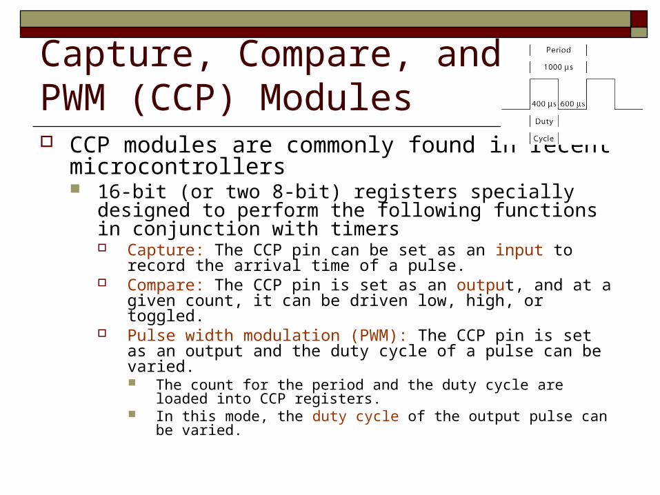
Capture, Compare, and PWM (CCP) Modules CCP modules are commonly found in recent
microcontrollers 16-bit (or two 8-bit) registers specially designed to
perform the following functions in conjunction with timers Capture: The CCP pin can be set as an input to record the arrival
time of a pulse. Compare: The CCP pin is set as an output, and at a given count,
it can be driven low, high, or toggled. Pulse width modulation (PWM): The CCP pin is set as an output
and the duty cycle of a pulse can be varied. The count for the period and the duty cycle are loaded into CCP
registers. In this mode, the duty cycle of the output pulse can be varied.


CCP (Capture, Compare, and PWM) Modules PIC18 Device may have 1, 2, or 5 CCP modules our PIC18F4550
have 2 CCP Each CCP module requires the use of a timer resource Capture or compare mode, the CCP module may use either
Timer1 or Timer3 to operate. PWM Timer2 is used
Each module is associated with A control register (CCPxCON) A data register (CCPRx) which consists of two 8-bit register:
CCPRxL and CCPRxH

Basic operation Each CCP module is comprised of two 8-bit registers: CCPR1H (high)
and CCPR1L (low) Called capture and compare register
Can operate as 16-bit Capture register, 16-bit Compare register, or 10-bit duty-cycle PWM register
Timer1 and Timer3 are used as clock resources for Capture and Compare registers
Timer2 is used as clock sources as PWM modules In PWM operation we use Timer 2 as a basic timer and Timer 1/3 as a
source for compare operation
/3/3

Timer2 special features Timer2 is an 8-bit counter. The values of TMR2 and PR2 are compared on
each clock cycle. When the two values are equal, the comparator
generates an output signal. This signal also resets the value of TMR2 to 00h
on the next cycle and drives the output counter/postscaler.

Control Register (CCP1CON)
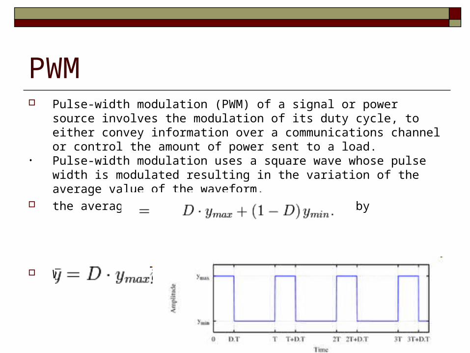
PWM Pulse-width modulation (PWM) of a signal or power source involves the
modulation of its duty cycle, to either convey information over a communications channel or control the amount of power sent to a load.
• Pulse-width modulation uses a square wave whose pulse width is modulated resulting in the variation of the average value of the waveform.
the average value of the waveform is given by
When Ymin =0
CCP in the Pulse Width Modulation (PWM) Mode (0 of 3)
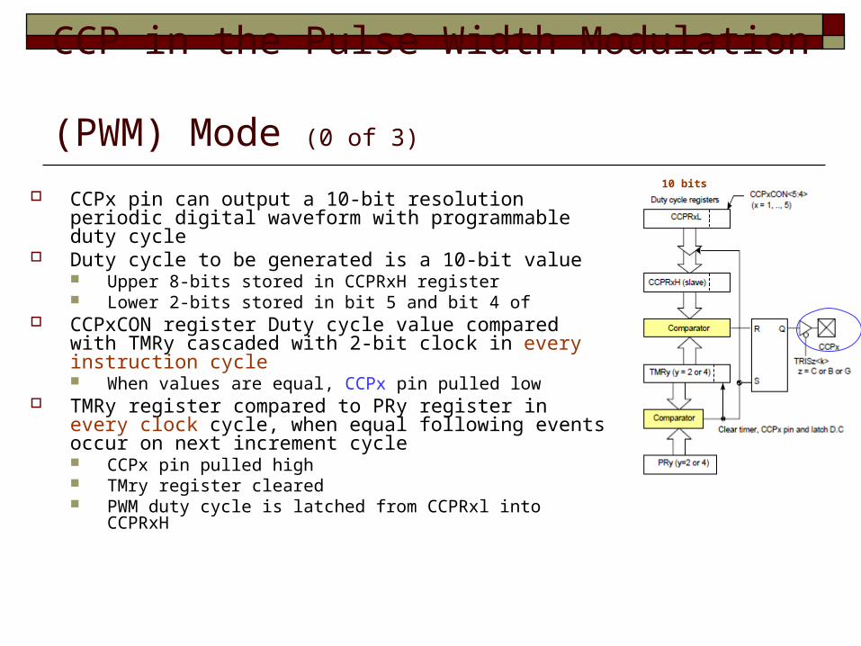
CCPx pin can output a 10-bit resolution periodic digital waveform with programmable duty cycle
Duty cycle to be generated is a 10-bit value Upper 8-bits stored in CCPRxH register Lower 2-bits stored in bit 5 and bit 4 of
CCPxCON register Duty cycle value compared with TMRy cascaded with 2-bit clock in every instruction cycle When values are equal, CCPx pin pulled low
TMRy register compared to PRy register in every clock cycle, when equal following events occur on next increment cycle CCPx pin pulled high TMry register cleared PWM duty cycle is latched from CCPRxl into CCPRxH
10 bits

Capture/Compare/PWM (CCP) Modules Two CCP modules are available (CCP1 and CCP2). In PWM mode, the two modules use Timer2 as a time base. Thus PWM
frequency is the same for CCP1 and CCP2. Each module has its own duty cycle.

CCP in the Pulse Width Modulation (PWM) Mode (1 of 3)
A CCP module in conjunction with Timer2 can be set up to output a pulse wave form for a given frequency and a duty cycle.
The CCP module uses a 10-bit number to specify the duty cycle.
The 8-bit number loaded into the PR2 register specify the PWM period.
PWM period and duty cycle can be calculated using the following

Example Configure CCP1 in PWM mode to generate a digital waveform with 40%
duty cycle and 10 KHz frequency assuming that the PIC18 MCU is running with a 32 MHz crystal oscillator. Assuming prescale=4 for timer 2 and timer 3 in 16 bit timer mode with prescale 1:1.
Timer setting Use Timer2 as the base timer of CCP1 through CCP5 for PWM mode Enable Timer3 in 16-bit mode with 1:1 prescaler Set Prescaler to Timer2 to 1:4 Period register value: PR2 = 32MHz /[4x4x10KHz]-1 = 199 Duty Cycle Value: CCPR1L = PR2+1*DutyCycle = 200x40% = 80
We ignor the least two bit that can be used as multiplication factor
00 no effect, , 11 multiply by 4

Another Example

PWM period and duty cycle
The main trap is that the PWM period is set by a 8-bit value and the duty cycle is controlled by a 10-bit value.
Example : let’s assume the period value is 99, thus the TMR2 value (8-bit value)
should grow from 0 to (99+1) = 100 (reset value) so the TMR2 extended value (10-bit value) should grow from 0 to
(99+1) * 4 = 400 and then the duty cycle value should vary from 0 (0% duty cycle) to
400 (100% duty cycle).

In our case If we use our PIC in OSC=8Mhz and the Timer2 prescaler=4
then the max output frequency when PR2=0….., freq=500000Hz the min output frequency when PR2=255….., freq=1953.125Hz PR2 value not exceed the 8bit max value (255) Duty cycle can’t exceed 4*(PR2+1) in 10bit mode Duty cycle can’t exceed DC*PR2 in 8 bit mode If PR2 value exceed 255 we can change the prescaler factor

Example Let’s assume that we need a 20kHz PWM period.
Fosc = 48MHz If Timer 2 prescaler =1 PR2=599>255 So we change the Timer2 prescaler=4 PR2=149
CCP in the PWM Mode (2 of 3)
When TMR2 is equal to PR2, the following three events occur in the next increment cycle: TMR2 is cleared. Pin RC2/CCP1 of PORTC is set high. The PWM duty-cycle byte is latched from
CCPR1L into CCPR1H. When CCPR1H and TMR2 match again for the
specified duty cycle, the CCP1 pin is cleared.

CCP in the PWM Mode (3 of 3)
To Initialize CCP1 in the PWM mode: Set up pin RC2/CCP1 of PORTC as output. Set up PWM period by writing to the PR2 register. Set up PWM duty cycle by writing to CCPR1L register
and Bit5-Bit4 of CCP1CON register. Set up TMR2 prescale value and Timer2 in timer mode by
writing to T2CON register. Enable CCP1 module in the PWM mode. Set up CCP1 by writing to the CCP1CON register.