ccnp tshoot 642-832 official certification guide - pearsoncmg
TRANSCRIPT


CCNP TSHOOT 642-832 Official Certification Guide
Kevin Wallace, CCIE No. 7945
Copyright © 2010 Pearson Education, Inc.
Published by:Cisco Press800 East 96th Street Indianapolis, IN 46240 USA
All rights reserved. No part of this book may be reproduced or transmitted in any form or by anymeans, electronic or mechanical, including photocopying, recording, or by any information storageand retrieval system, without written permission from the publisher, except for the inclusion of briefquotations in a review.
Printed in the United States of America
First Printing February 2010
Library of Congress Cataloging-in-Publication Data:
Wallace, Kevin, CCNP.CCNP TSHOOT 642-832 official certification guide / Kevin Wallace.
p. cm.Includes index.ISBN-13: 978-1-58705-844-8ISBN-10: 1-58705-844-8
1. Computer networks—Management—Examinations—Study guides. 2. Telecommunications engineers—Certification. 3. Cisco Systems, Inc.—Examinations—Study guides. I. Title.
TK5105.8.C57W35 2010004.6076—dc22
Warning and Disclaimer
This book is designed to provide information about the CCNP TSHOOT Exam (Exam 642-832) for theCCNP Routing and Switching certification. Every effort has been made to make this book as completeand as accurate as possible, but no warranty or fitness is implied.
The information is provided on an “as is” basis. The authors, Cisco Press, and Cisco Systems, Inc. shallhave neither liability nor responsibility to any person or entity with respect to any loss or damagesarising from the information contained in this book or from the use of the discs or programs that mayaccompany it.
The opinions expressed in this book belong to the author and are not necessarily those of Cisco Systems, Inc.
Trademark Acknowledgments
All terms mentioned in this book that are known to be trademarks or service marks have been appropriate-ly capitalized. Cisco Press or Cisco Systems, Inc., cannot attest to the accuracy of this information. Use ofa term in this book should not be regarded as affecting the validity of any trademark or service mark.
Corporate and Government Sales
The publisher offers excellent discounts on this book when ordered in quantity for bulk purchases or spe-cial sales, which may include electronic versions and/or custom covers and content particular to your busi-ness, training goals, marketing focus, and branding interests. For more information, please contact: U.S.Corporate and Government Sales 1-800-382-3419 [email protected]
For sales outside the United States please contact: International Sales [email protected]
ii CCNP TSHOOT 642-832 Official Certification Guide

xvii
Foreword
CCNP TSHOOT 642-832 Official Certification Guide is an excellent self-studyresource for the CCNP TSHOOT exam. Passing this exam is a crucial step to attaining thevalued CCNP Routing and Switching certification.
Gaining certification in Cisco technology is key to the continuing educational develop-ment of today’s networking professional. Through certification programs, Cisco validatesthe skills and expertise required to effectively manage the modern enterprise network.
Cisco Press Certification Guides and preparation materials offer exceptional—and flexi-ble—access to the knowledge and information required to stay current in your field ofexpertise or to gain new skills. Whether used as a supplement to more traditional trainingor as a primary source of learning, these materials offer users the information and knowl-edge validation required to gain new understanding and proficiencies.
Developed in conjunction with the Cisco certifications and training team, Cisco Pressbooks are the only self-study books authorized by Cisco and offer students a series ofexam practice tools and resource materials to help ensure that learners fully grasp theconcepts and information presented.
Additional authorized Cisco instructor-led courses, e-learning, labs, and simulations areavailable exclusively from Cisco Learning Solutions Partners worldwide. To learn more,visit http://www.cisco.com/go/training.
I hope that you find these materials to be an enriching and useful part of your exampreparation.
Erik UllandersonManager, Global CertificationsLearning@CiscoJanuary 2010

xviii CCNP TSHOOT 642-832 Official Certification Guide
Introduction: Overview of Certification and
How to Succeed
Professional certifications have been an important part of the computing industry formany years and will continue to become more important. Many reasons exist for thesecertifications, but the most popularly cited reason is that of credibility. All other consid-erations held equal, the certified employee/consultant/job candidate is considered morevaluable than one who is not.
Objectives and Methods
The most important and somewhat obvious objective of this book is to help you pass theCisco CCNP TSHOOT exam (Exam 642-832). In fact, if the primary objective of thisbook were different, the book’s title would be misleading; however, the methods used inthis book to help you pass the TSHOOT exam are designed to also make you much moreknowledgeable about how to do your job. Although this book and the accompanyingCD-ROM have many exam preparation tasks and example test questions, the method inwhich they are used is not to simply make you memorize as many questions and answersas you possibly can.
The methodology of this book helps you discover the exam topics about which you needmore review, fully understand and remember exam topic details, and prove to yourselfthat you have retained your knowledge of those topics. So this book helps you pass notby memorization, but by helping you truly learn and understand the topics. TheTSHOOT exam is just one of the foundation topics in the CCNP Routing and Switchingcertification, and the knowledge contained within is vitally important to consider your-self a truly skilled routing and switching engineer or specialist. This book would do you adisservice if it did not attempt to help you learn the material. To that end, the book canhelp you pass the TSHOOT exam by using the following methods:
■ Covering all of the exam topics and helping you discover which exam topics youhave not mastered
■ Providing explanations and information to fill in your knowledge gaps
■ Supplying multiple troubleshooting case studies with diagrams and diagnostic out-put that enhance your ability to resolve trouble tickets presented in the exam envi-ronment, in addition to real-world troubleshooting issues you might encounter
■ Providing practice exercises on exam topics, presented in each chapter and on theenclosed CD-ROM
Who Should Read This Book?
This book is not designed to be a general networking topics book, although it can beused for that purpose. This book is intended to tremendously increase your chances ofpassing the Cisco TSHOOT exam. Although other objectives can be achieved from usingthis book, the book is written with one goal in mind: to help you pass the exam.

xix
The TSHOOT exam is primarily based on the content of the Cisco TSHOOT course. Youshould have either taken the course, read through the TSHOOT course material or thisbook, or have a couple of years of troubleshooting experience.
Cisco Certifications and Exams
Cisco offers four levels of routing and switching certification, each with an increasinglevel of proficiency: Entry, Associate, Professional, and Expert. These are commonlyknown by their acronyms CCENT (Cisco Certified Entry Networking Technician), CCNA(Cisco Certified Network Associate), CCNP (Cisco Certified Network Professional), andCCIE (Cisco Certified Internetworking Expert). There are others as well, but this bookfocuses on the certifications for enterprise networks.
For the CCNP Routing and Switching certification, you must pass exams on a series ofCCNP topics, including the SWITCH, ROUTE, and TSHOOT exams. For most exams,Cisco does not publish the scores needed for passing. You need to take the exam to findthat out for yourself.
To see the most current requirements for the CCNP Routing and Switching certification,go to cisco.com and click Training and Events. There you can find out other exam detailssuch as exam topics and how to register for an exam.
The strategy you use to prepare for the TSHOOT exam might be slightly different thanstrategies used by other readers, mainly based on the skills, knowledge, and experienceyou have already obtained. For example, if you have attended the TSHOOT course, youmight take a different approach than someone who learned troubleshooting through on-the-job training. Regardless of the strategy you use or the background you have, thisbook is designed to help you get to the point where you can pass the exam with the leastamount of time required.
How This Book Is Organized
Although this book can be read cover to cover, it is designed to be flexible and enableyou to easily move between chapters to cover only the material that you need more workwith. The chapters can be covered in any order, although some chapters are related andbuild upon each other. If you do intend to read them all, the order in the book is an excel-lent sequence to use.
Each core chapter covers a subset of the topics on the CCNP TSHOOT exam. The chap-ters are organized into parts, covering the following topics:
■ Chapter 1, “Introduction to Network Maintenance”: This chapter discusses theimportance of proactive maintenance tasks, as opposed to the reactive maintenancerequired to address a problem. Also discussed in this chapter is a collection of com-monly used maintenance approaches.
Next, this chapter lists common maintenance tasks, emphasizes the importance ofregularly scheduled maintenance, and summarizes critical areas of network perform-ance. Finally, this chapter identifies how to compile a set of network maintenancetools that complement your network maintenance plan.

xx CCNP TSHOOT 642-832 Official Certification Guide
■ Chapter 2, “Introduction to Troubleshooting Processes”: This chapter address-es troubleshooting fundamentals, discusses the benefits of having a structured trou-bleshooting model, and discusses several popular troubleshooting models.
Also discussed is each subprocess in a structured troubleshooting approach. Finally,this chapter shows how maintenance processes and troubleshooting process canwork in tandem to complement one another.
■ Chapter 3, “The Maintenance and Troubleshooting Toolbox”: This chaptershows how a few readily accessible Cisco IOS commands can be used to quicklygather information, as part of a structured troubleshooting process.
This chapter also introduces a collection of specialized features, such as SPAN,RSPAN, SMTP, NetFlow, and EEM, which can be used to collect information abouta problem.
■ Chapter 4, “Basic Cisco Catalyst Switch Troubleshooting”: This chapterreviews the basics of Layer 2 switch operation and demonstrates a collection ofCisco Catalyst show commands that can be used to quickly gather information, aspart of a structured troubleshooting process.
Also, this chapter introduces spanning tree protocol (STP), which allows a Layer 2topology to have redundant links while avoiding the side effects of a looped Layer 2topology, such as a broadcast storm. You then learn strategies for troubleshooting anSTP issue.
Finally, troubleshooting an EtherChannel connection is addressed. This chapter con-cludes with a trouble ticket and an associated topology. You are also given showcommand output (baseline output and output collected after the reported issueoccurred). Based on the information provided, you hypothesize an underlying causefor the reported issue and develop a solution. You can then compare your solutionwith a suggested solution.
■ Chapter 5, “Advanced Cisco Catalyst Switch Troubleshooting”: This chapterbegins by contrasting Layer 3 switches and routers. Troubleshooting procedures arealso compared for these platforms. Two approaches for routing packets using Layer 3switches are also discussed. These approaches are using routed ports and usingswitched virtual interfaces (SVIs).
Next, this chapter discusses three approaches to providing first-hop router redundan-cy. Options include HSRP, VRRP, and GLBP. Troubleshooting strategies are dis-cussed for HSRP with suggestions on how to modify those strategies for trou-bleshooting VRRP and GLBP. Examined next is the architecture of a Cisco Catalystswitch and the different architectural components that could become troubleshoot-ing targets. You are presented with a series of show commands used to gather infor-mation about different aspects of a switch’s performance.
Finally, this chapter presents you with a trouble ticket and an associated topology.You are also given show and debug command output (baseline output and outputcollected after a reported issue occurred). Based on the information provided, youhypothesize an underlying cause for the reported issue and develop a solution. Youcan then compare your solution with a suggested solution.

xxi
■ Chapter 6, “Introduction to Troubleshooting Routing Protocols”: This chapterbegins by reviewing basic routing concepts. For example, you examine the changesto a frame’s header as that frame’s data is routed from one network to another. Yousee how Layer 2 information can be learned and stored in a router. Cisco ExpressForwarding (CEF) is also discussed. Additionally, you are presented with a collectionof show commands, useful for troubleshooting IP routing.
Next, this chapter generically reviews how an IP routing protocol’s data structuresinteract with a router’s IP routing table. Then, EIGRP’s data structures are consid-ered, followed by a review of basic EIGRP operation. Again, you are presented witha collection of show and debug commands useful for troubleshooting various EIGRPoperations.
Finally, this chapter challenges you with a trouble ticket and an associated topology.You are also given show command output. Based on the information provided, youhypothesize an underlying cause for the reported issue and develop a solution. Youcan then compare your solution with a suggested solution.
■ Chapter 7, “OSPF and Route Redistribution Troubleshooting”: This chapterbegins by introducing you to OSPF’s routing structures, followed by a review ofOSPF operation. You are then presented with a collection of show and debug com-mands useful for troubleshooting OSPF operations.
This chapter next presents you with a trouble ticket and an associated topology. Youare also given show command output. Based on the information provided, youhypothesize an underlying cause for the reported issues and develop solutions. Youcan then compare your solutions with the suggested solutions.
This chapter also introduces the concept of route redistribution and discusses how aroute from one routing process can be injected into a different routing process.Common route redistribution troubleshooting targets are identified, along withstrategies for troubleshooting route redistribution.
Finally, this chapter challenges you with another trouble ticket and an associatedtopology. You are also given show command output. Based on the information pro-vided, you hypothesize an underlying cause for the reported issue and develop asolution. You can then compare your solution with a suggested solution.
■ Chapter 8, “Troubleshooting BGP and Router Performance Issues”: Thischapter begins by introducing you to BGP’s data structures, followed by a review ofBGP operation. You are then presented with a collection of show and debug com-mands useful for troubleshooting BGP operations.
This chapter next presents you with a trouble ticket and an associated topology. Youare given show command output. Based on the information provided, you hypothe-size an underlying cause for the reported issue and develop a solution. You can thencompare your solutions with the suggested solutions.
Finally, this chapter discusses how to troubleshoot performance issues on a router,focusing on CPU utilization, packet-switching modes, and memory utilization.

xxii CCNP TSHOOT 642-832 Official Certification Guide
■ Chapter 9, “Security Troubleshooting”: This chapter begins by reviewing varioussecurity measures that might be put in place on Cisco routers and switches to pro-tect three different planes of network operation. These planes are the managementplane, the control plane, and the data plane. Once you review these security meas-ures, this chapter considers how your troubleshooting efforts might be impacted byhaving various layers of security in place.
Next, this chapter describes the basic operation and troubleshooting tips for CiscoIOS firewalls and AAA services. Although complete configuration details for CiscoIOS firewalls and AAA is beyond the scope of the TSHOOT curriculum, as a refer-ence, this chapter does provide a couple of basic configuration examples with anexplanation of the syntax used.
Finally, this chapter presents you with a trouble ticket and an associated topology.You are also given show command output and a syntax reference. Based on theinformation provided, you hypothesize how to correct the reported issues. You canthen compare your solutions with the suggested solutions.
■ Chapter 10, “IP Services Troubleshooting”: This chapter begins by reviewingthe purpose and basic operation of Network Address Translation (NAT). As a refer-ence, sample topologies are provided, along with their configurations. Common NATtroubleshooting targets are identified, and a syntax reference is provided to aid introubleshooting NAT issues.
Next, this chapter reviews Dynamic Host Configuration Protocol (DHCP) operationand various types of DHCP messages. You are given three configuration examplescorresponding to the three roles a router might play in a DHCP environment: DHCPrelay agent, DHCP client, and DHCP server. Common DHCP troubleshooting targetsare reviewed, along with recommended DHCP troubleshooting practices. This sec-tion also presents a collection of commands that could prove to be useful in trou-bleshooting a suspected DHCP issue.
Finally, this chapter presents you with a trouble ticket and an associated topology.You are also given show and debug command output, which confirms the reportedissue. Then, you are challenged to hypothesize how to correct the reported issue.You can then compare your solution with a suggested solution.
■ Chapter 11, “IP Communications Troubleshooting”: This chapter begins byintroducing you to design and troubleshooting considerations that arise when addingvoice traffic to a data network. Several protocols are involved when a Cisco IP Phoneregisters with its call agent in order to place and receive voice calls. You review thefunction of these protocols along with recommendations for troubleshooting voiceissues. One of the major troubleshooting targets for voice networks involves qualityof service. Therefore, this chapter provides overview of quality of service configura-tion, verification, and troubleshooting commands. Additionally, this chapter consid-ers video traffic in an IP network, including video’s unique design and troubleshoot-ing challenges.

xxiii
Also, video-based networks often rely on an infrastructure that supports IP multicas-ting. Because multicasting has not been addressed in any depth thus far in this book,this chapter serves as a primer to multicast technologies. Included in this primer arecommands used to configure, monitor, and troubleshoot multicast networks. Thechapter next considers common video troubleshooting issues and recommends reso-lutions for those issues.
Finally, this chapter presents you with two trouble tickets focused on unified com-munications. You are presented with a topology used by both trouble tickets, inaddition to a collection of show command output. For each trouble ticket, you arechallenged to hypothesize how to correct the reported issue. You can also compareyour solutions with suggested solutions.
■ Chapter 12, “IPv6 Troubleshooting”: This chapter introduces the purpose andstructure of IP version 6 (IPv6) addressing. You consider the various types of IPv6addresses, routing protocols supporting IPv6, and basic syntax for enabling a routerto route IPv6 traffic. A sample configuration is provided to illustrate the configura-tion of a router to support IPv6. Additionally, as an organization is migrating fromIPv4 to IPv6, there might be portions of the network that are still running IPv4 withother portions of the network running IPv6. For IPv6 traffic to span an IPv4 portionof the network, one option is to create a tunnel spanning the IPv4 network. Then,IPv6 traffic can travel inside the tunnel to transit the IPv4 network. This section dis-cusses the syntax and provides an example of tunneling IPv6 over an IPv4 tunnel.
This chapter also contrasts the characteristics of two versions of OSPF, specificallyOSPFv2 and OSPFv3. OSPFv3 can support the routing of IPv6 networks, whereasOSPFv2 cannot. OSPFv3 configuration syntax is presented, along with a sample con-figuration. You are also provided with a collection of verification troubleshootingcommands and a listing of common OSPFv3 issues.
Next, this chapter presents you with a trouble ticket addressing a network experienc-ing OSPF adjacency issues. You are presented with a collection of show and debugcommand output and challenged to resolve a series of misconfigurations. Suggestedsolutions are provided.
Also, this chapter contrasts the characteristics of RIP next generation (RIPng) withRIPv2. You are given a set of RIPng configuration commands along with a sampleconfiguration. From a troubleshooting perspective, you compare RIPng trou-bleshooting commands with those commands used to troubleshoot RIPv1 andRIPv2. This chapter also discusses some of the more common RIPng troubleshoot-ing issues you might encounter.
Finally, this chapter challenges you to resolve a couple of RIPng issues beingobserved in a network. Specifically, load balancing and default route advertisementsare not behaving as expected. To assist in your troubleshooting efforts, you arearmed with a collection of show and debug command output. Your proposed solu-tions can then be compared with suggested solutions.

xxiv CCNP TSHOOT 642-832 Official Certification Guide
■ Chapter 13, “Advanced Services Troubleshooting”: This chapter introducesyou to Cisco’s Application Network Services (ANS) architecture. Cisco ANS includesmultiple pieces of dedicated equipment aimed at optimizing the performance of net-work-based applications (for example, improving the response time of a corporateweb server for users at a remote office). Although this chapter introduces a collec-tion of Cisco ANS components, the primary focus is on Cisco IOS features that canimprove application performance. Specifically, the Cisco IOS features addressed areNetFlow, IP SLAs, NBAR, and QoS.
Also, this chapter addresses the troubleshooting of wireless networks, and it beginsby contrasting autonomous and split-MAC wireless network architectures. Wirednetwork issues that could impact wireless networks are then highlighted. Theseissues include power, VLAN, security, DHCP, and QoS issues.
■ Chapter 14, “Large Enterprise Network Troubleshooting”: This chapter beginsby identifying a collection of technologies that might become troubleshooting tar-gets for a remote office network. The primary technologies focused on are VirtualPrivate Network (VPN) technologies. Sample syntax is provided for a VPN usingIPsec and GRE. Also, several useful show commands are provided as a troubleshoot-ing reference.
Finally, this chapter discusses the troubleshooting of complex networks, and beginsby identifying how multiple network technologies map to the seven layers of theOSI model. Also, you are given a list of resources a troubleshooter should have priorto troubleshooting a complex enterprise network. Finally, this chapter reviews keypoints from all trouble tickets previously presented.
■ Chapter 15, “Final Preparation”: This chapter identifies tools for final exampreparation and helps you develop an effective study plan.
Appendix A has the answers to the “Do I Know This Already” quizzes and an onlineappendix tells you how to find any updates should there be changes to the exam.
Each chapter in the book uses several features to help you make the best use of yourtime in that chapter. The features are as follows:
■ Assessment: Each chapter begins with a “Do I Know This Already?” quiz that helpsyou determine the amount of time you need to spend studying each topic of thechapter. If you intend to read the entire chapter, you can save the quiz for later use.Questions are all multiple-choice, to give a quick assessment of your knowledge.
■ Foundation Topics: This is the core section of each chapter that explains the proto-cols, concepts, configuration, and troubleshooting strategies for the topics in thechapter.
■ Exam Preparation Tasks: At the end of each chapter, this section collects key top-ics, references to memory table exercises to be completed as memorization practice,key terms to define, and a command reference that summarizes any relevant com-mands presented in the chapter.
xxv
Finally, the companion CD-ROM contains practice CCNP TSHOOT questions to rein-force your understanding of the book’s concepts. Be aware that the TSHOOT exam willprimarily be made up of trouble tickets you need to resolve. Mastery of the topics cov-ered by the CD-based questions, however, will help equip you with the tools needed toeffectively troubleshoot the trouble tickets presented on the exam.
The CD also contains the Memory Table exercises and answer keys.
How to Use This Book for Study
Retention and recall are the two features of human memory most closely related to per-formance on tests. This exam-preparation guide focuses on increasing both retention andrecall of the topics on the exam. The other human characteristic involved in successfullypassing the exam is intelligence; this book does not address that issue!
This book is designed with features to help you increase retention and recall. It does thisin the following ways:
■ By providing succinct and complete methods of helping you determine what yourecall easily and what you do not recall at all.
■ By referencing the portions of the book that review those concepts you most needto recall, so you can quickly be reminded about a fact or concept. Repeating infor-mation that connects to another concept helps retention, and describing the sameconcept in several ways throughout a chapter increases the number of connectors tothe same pieces of information.
■ Finally, accompanying this book is a CD-ROM that has questions covering trou-bleshooting theory, tools, and methodologies. Familiarity with these troubleshootingresources can help you be more efficient when diagnosing and resolving a reportednetwork issue.
When taking the “Do I Know This Already?” assessment quizzes in each chapter, makesure that you treat yourself and your knowledge fairly. If you come across a question thatmakes you guess at an answer, mark it wrong immediately. This forces you to readthrough the part of the chapter that relates to that question and forces you to learn itmore thoroughly.
If you find that you do well on the assessment quizzes, it still might be wise to quicklyskim through each chapter to find sections or topics that do not readily come to mind.Look for the Key Topics icons. Sometimes even reading through the detailed table of con-tents will reveal topics that are unfamiliar or unclear. If that happens to you, mark thosechapters or topics, and spend time working through those parts of the book.
CCNP TSHOOT Exam Topics
Carefully consider the exam topics Cisco has posted on its website as you study, particu-larly for clues to how deeply you should know each topic. Also, you can develop a broad-er knowledge of the subject matter by reading and studying the topics presented in this

xxvi CCNP TSHOOT 642-832 Official Certification Guide
book. Remember that it is in your best interest to become proficient in each of the CCNPsubjects. When it is time to use what you have learned, being well rounded counts morethan being well tested.
Table I-1 shows the official exam topics for the TSHOOT exam, as posted on cisco.com.Note that Cisco has occasionally changed exam topics without changing the exam num-ber, so do not be alarmed if small changes in the exam topics occur over time. When indoubt, go to cisco.com and click Training and Events.
Table I-1 CCNP TSHOOT Exam Topics
Chapters Where
Exam Topics
Exam Topics Are Covered
Maintain and monitor network performance
Develop a plan to monitor and manage a network Chapters 1–3 and 14Perform network monitoring using IOS toolsPerform routine IOS device maintenanceIsolate sub-optimal internetwork operation at the correctly defined OSI Model layer
Troubleshooting IPv4 and IPv6 routing protocols and IP services in a
multiprotocol system network
Troubleshoot EIGRP Chapters 5–8, 10,Troubleshoot OSPF and 12Troubleshoot eBGPTroubleshoot routing redistribution solutionTroubleshoot a DHCP client and server solutionTroubleshoot NAT Troubleshoot first-hop redundancy protocolsTroubleshoot IPv6 routingTroubleshoot IPv6 and IPv4 interoperability
Troubleshoot switch-based features
Troubleshoot switch-to-switch connectivity for a Chapters 4–5, 11,VLAN-based solution and 13Troubleshoot loop prevention for a VLAN-based solutionTroubleshoot access ports for a VLAN-based solutionTroubleshoot private VLANSTroubleshoot port securityTroubleshoot general switch securityTroubleshoot VACL and PACLTroubleshoot switch virtual interfaces (SVIs)Troubleshoot switch supervisor redundancyTroubleshoot switch support of advanced servicesTroubleshoot a VoIP support solutionTroubleshoot a video support solution

xxvii
Table I-1 CCNP TSHOOT Exam Topics (Continued)
Chapters Where
Exam Topics
Exam Topics Are Covered
Troubleshoot Cisco router and switch device hardening
Troubleshoot Layer 3 security Chapters 9 and 10Troubleshoot issues related to ACLs used to secure access to Cisco routersTroubleshoot configuration issues related to accessing an AAA server for authentication purposesTroubleshoot security issues related to IOS services
For More Information
If you have any comments about the book, you can submit those via the ciscopress.comwebsite. Just go to the website, select Contact Us, and type your message. Cisco mightmake changes that affect the CCNP Routing and Switching certification from time totime. You should always check cisco.com for the latest details. Also, you can look towww.ciscopress.com/title/1587058448, where we publish any information pertinent tohow you might use this book differently in light of Cisco’s future changes. For example,if Cisco decided to remove a major topic from the exam, it might post that on its website;Cisco Press will make an effort to list that information as well via an online updatesappendix.

This chapter covers the following subjects:
Resolving InterVLAN Routing Issues: This section beginsby contrasting Layer 3 switches and routers. Troubleshootingprocedures are also compared for these platforms. Lastly, thissection discusses two approaches for routing packets usingLayer 3 switches: routed ports and Switched Virtual Inter-faces (SVIs).
Router Redundancy Troubleshooting: This section dis-cusses three approaches to providing first-hop router redun-dancy. Options include: Hot Standby Routing Protocol(HSRP), Virtual Router Redundancy Protocol (VRRP), andGateway Load Balancing Protocol (GLBP). Troubleshootingstrategies are discussed for HSRP with suggestions on how tomodify those strategies for troubleshooting VRRP and GLBP.
Cisco Catalyst Switch Performance Tuning: This sectionexamines the architecture of a Cisco Catalyst switch andpoints out different architectural components that couldbecome troubleshooting targets. Also, you are presented witha series of show commands used to gather information aboutdifferent aspects of a switch’s performance.
Trouble Ticket: HSRP: This section presents you with atrouble ticket and an associated topology. You are also givenshow and debug command output (baseline output andoutput collected after a reported issue occurred). Based on theinformation provided, you hypothesize an underlying causefor the reported issue and develop a solution. You can thencompare your solution with a suggested solution.

CHAPTER 5
Advanced Cisco Catalyst SwitchTroubleshooting
This chapter builds on Chapter 4, “Basic Cisco Catalyst Switch Troubleshooting,” by con-tinuing to focus on troubleshooting Cisco Catalyst Switch platforms. Although the termswitch might conjure up the image of a Layer 2 device, many modern switches can alsoroute. Specifically, many switches can make forwarding decisions based on Layer 3 infor-mation (for example, IP address information). Therefore, this chapter starts by discussing acouple of ways to make a Layer 3 (or multilayer) switch perform routing.
Next, because many Layer 3 switches reside in a wiring closet, these switches might verywell act as the default gateway for endpoints (for example, user PCs). Rather than havingthis switch (or perhaps a router at the distribution layer) become a single point of failurefor endpoints relying on the IP address maintained by that switch (or router), you cantake advantage of a first-hop redundancy protocol. A first-hop redundancy protocol al-lows clients to continue to reach their default gateway’s IP address, even if the Layer 3switch or router that had been servicing that IP address becomes available. This chaptercontrasts three first-hop redundancy protocols and discusses the troubleshooting of first-hop redundancy.
Often a trouble reported by a user comes in some variation of, “The network is slow.” Al-though such a description is less than insightful, troubleshooters are likely to encounternetwork performance issues resulting in a poor user experience. This chapter focuses ontroubleshooting performance problems that originate from a Cisco Catalyst switch.
Finally, this chapter presents another trouble ticket. This trouble ticket describes a first-hop redundancy protocol not operating as expected. Given a collection of show anddebug output, you are challenged to determine the underlying cause of the issue andformulate a solution.
“Do I Know This Already?” Quiz
The “Do I Know This Already?” quiz helps you determine your level of knowledge of thischapter’s topics before you begin. Table 5-1 details the major topics discussed in this chap-ter and their corresponding quiz questions.
Table 5-1 “Do I Know This Already?” Section-to-Question Mapping
Foundation Topics Section Questions
Resolving InterVLAN Routing Issues 1–3
continues

108 CCNP TSHOOT 642-832 Official Certification Guide
Router Redundancy Troubleshooting 4–7
Cisco Catalyst Switch Performance Troubleshooting 8–10
1. What are two differences between Layer 3 switches and routers? (Choose two.)
a. Layer 3 switches do not maintain a routing table.
b. Layer 3 switches usually forward traffic faster than routers.
c. Layer 3 switches support more interface types than routers.
d. Layer 3 switches usually support fewer features than routers.
2. What type of special memory is used by Layer 3 switches, and not routers, that sup-ports very rapid route lookups?
a. NBAR
b. TCAM
c. NetFlow
d. MIB
3. What type of interface can be created on a Layer 3 switch to support routing be-tween VLANs on that switch?
a. BVI
b. VPI
c. SVI
d. VCI
4. What is the default priority for an HSRP interface?
a. 0
b. 100
c. 256
d. 1000
5. What is the name for the router in a VRRP virtual router group that is actively for-warding traffic on behalf of the virtual router group?
a. virtual forwarder
b. active virtual gateway
c. virtual router master
d. active virtual forwarder
Table 5-1 “Do I Know This Already?” Section-to-Question Mapping (Continued)
Foundation Topics Section Questions
Chapter 5: Advanced Cisco Catalyst Switch Troubleshooting 109
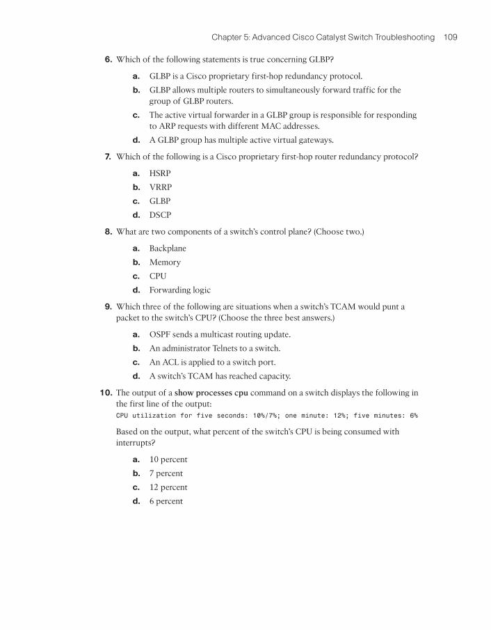
6. Which of the following statements is true concerning GLBP?
a. GLBP is a Cisco proprietary first-hop redundancy protocol.
b. GLBP allows multiple routers to simultaneously forward traffic for thegroup of GLBP routers.
c. The active virtual forwarder in a GLBP group is responsible for respondingto ARP requests with different MAC addresses.
d. A GLBP group has multiple active virtual gateways.
7. Which of the following is a Cisco proprietary first-hop router redundancy protocol?
a. HSRP
b. VRRP
c. GLBP
d. DSCP
8. What are two components of a switch’s control plane? (Choose two.)
a. Backplane
b. Memory
c. CPU
d. Forwarding logic
9. Which three of the following are situations when a switch’s TCAM would punt apacket to the switch’s CPU? (Choose the three best answers.)
a. OSPF sends a multicast routing update.
b. An administrator Telnets to a switch.
c. An ACL is applied to a switch port.
d. A switch’s TCAM has reached capacity.
10. The output of a show processes cpu command on a switch displays the following inthe first line of the output:CPU utilization for five seconds: 10%/7%; one minute: 12%; five minutes: 6%
Based on the output, what percent of the switch’s CPU is being consumed withinterrupts?
a. 10 percent
b. 7 percent
c. 12 percent
d. 6 percent

R1
Fa 1/1/1.1
Fa 1/1/1.2
Fa 1/1/1VLAN 100VLAN 200
Fa 1/1/1
Gig
0/2
Gig 0/3
VLAN 100
Trun
k
PC2192.168.2.10/24
VLAN 200
PC1192.168.1.10/24
VLAN 100
SW1
Gig 0/1
VLAN 100
R1
Figure 5-1 Router on a Stick
Foundation Topics
Resolving InterVLAN Routing Issues
As mentioned in Chapter 4, “Basic Cisco Catalyst Switch Troubleshooting,” for traffic topass from one VLAN to another VLAN, that traffic has to be routed. Several years ago,one popular approach to performing interVLAN routing with a Layer 2 switch was to cre-ate a router on a stick topology, where a Layer 2 switch is interconnected with a router viaa trunk connection, as seen in Figure 5-1.
110 CCNP TSHOOT 642-832 Official Certification Guide
In Figure 5-1, router R1’s Fast Ethernet 1/1/1 interface has two subinterfaces, one for eachVLAN. Router R1 can route between VLANs 100 and 200, while simultaneously receivingand transmitting traffic over the trunk connection to the switch.
More recently, many switches have risen above their humble Layer 2 beginnings andstarted to route traffic. Some literature refers to these switches that can route as Layer 3
switches. Other sources might call such switches multilayer switches, because of thecapability of a switch to make forwarding decisions based on information from multiplelayers of the OSI model.
This section refers to these switches as Layer 3 switches because the focus is on the capa-bility of the switches to route traffic based on Layer 3 information (that is, IP address in-formation). Specifically, this section discusses troubleshooting Layer 3 switch issues andcontrasts troubleshooting a Layer 3 switch versus a router.
Contrasting Layer 3 Switches with Routers
Because a Layer 3 switch performs many of the same functions as a router, it is importantfor a troubleshooter to distinguish between commonalities and differences in these twoplatforms.
Chapter 5: Advanced Cisco Catalyst Switch Troubleshooting 111
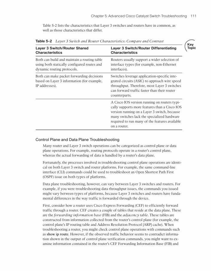
Table 5-2 lists the characteristics that Layer 3 switches and routers have in common, aswell as those characteristics that differ.
Control Plane and Data Plane Troubleshooting
Many router and Layer 3 switch operations can be categorized as control plane or dataplane operations. For example, routing protocols operate in a router’s control plane,whereas the actual forwarding of data is handled by a router’s data plane.
Fortunately, the processes involved in troubleshooting control plane operations are identi-cal on both Layer 3 switch and router platforms. For example, the same command-lineinterface (CLI) commands could be used to troubleshoot an Open Shortest Path First(OSPF) issue on both types of platforms.
Data plane troubleshooting, however, can vary between Layer 3 switches and routers. Forexample, if you were troubleshooting data throughput issues, the commands you issuedmight vary between types of platforms, because Layer 3 switches and routers have funda-mental differences in the way traffic is forwarded through the device.
First, consider how a router uses Cisco Express Forwarding (CEF) to efficiently forwardtraffic through a router. CEF creates a couple of tables that reside at the data plane. Theseare the forwarding information base (FIB) and the adjacency table. These tables areconstructed from information collected from the router’s control plane (for example, thecontrol plane’s IP routing table and Address Resolution Protocol [ARP] cache). Whentroubleshooting a router, you might check control plane operations with commands suchas show ip route. However, if the observed traffic behavior seems to contradict informa-tion shown in the output of control plane verification commands, you might want to ex-amine information contained in the router’s CEF Forwarding Information Base (FIB) and
Key Topic
Table 5-2 Layer 3 Switch and Router Characteristics: Compare and Contrast
Layer 3 Switch/Router Shared
Characteristics
Layer 3 Switch/Router Differentiating
Characteristics
Both can build and maintain a routing tableusing both statically configured routes anddynamic routing protocols.
Routers usually support a wider selection ofinterface types (for example, non-Ethernetinterfaces).
Both can make packet forwarding decisionsbased on Layer 3 information (for example,IP addresses).
Switches leverage application-specific inte-grated circuits (ASIC) to approach wire speedthroughput. Therefore, most Layer 3 switchescan forward traffic faster than their routercounterparts.
A Cisco IOS version running on routers typi-cally supports more features than a Cisco IOSversion running on a Layer 3 switch, becausemany switches lack the specialized hardwarerequired to run many of the features availableon a router.

112 CCNP TSHOOT 642-832 Official Certification Guide
Table 5-3 Router Data Plan Verification Commands
Command Description
show ip cef Displays the router’s Layer 3 forwarding information, in addition to multicast,broadcast, and local IP addresses.
showadjacency
Verifies that a valid adjacency exists for a connected host.
Key Topic
adjacency tables. You can use the commands presented in Table 5-3 to view informationcontained in a router’s FIB and adjacency table.
Example 5-1 and Example 5-2 provide sample output from the show ip cef and showadjacency commands, respectively.
Example 5-1 show ip cef Command Output
R4# show ip cef
Prefix Next Hop Interface
0.0.0.0/0 10.3.3.1 FastEthernet0/0
0.0.0.0/32 receive
10.1.1.0/24 10.3.3.1 FastEthernet0/0
10.1.1.2/32 10.3.3.1 FastEthernet0/0
10.3.3.0/24 attached FastEthernet0/0
10.3.3.0/32 receive
10.3.3.1/32 10.3.3.1 FastEthernet0/0
10.3.3.2/32 receive
10.3.3.255/32 receive
10.4.4.0/24 10.3.3.1 FastEthernet0/0
10.5.5.0/24 10.3.3.1 FastEthernet0/0
10.7.7.0/24 10.3.3.1 FastEthernet0/0
10.7.7.2/32 10.3.3.1 FastEthernet0/0
10.8.8.0/24 attached FastEthernet0/1
10.8.8.0/32 receive
10.8.8.1/32 receive
10.8.8.4/32 10.8.8.4 FastEthernet0/1
10.8.8.5/32 10.8.8.5 FastEthernet0/1
10.8.8.6/32 10.8.8.6 FastEthernet0/1
10.8.8.7/32 10.8.8.7 FastEthernet0/1
10.8.8.255/32 receive
192.168.0.0/24 10.3.3.1 FastEthernet0/0
224.0.0.0/4 drop
224.0.0.0/24 receive
255.255.255.255/32 receive

Chapter 5: Advanced Cisco Catalyst Switch Troubleshooting 113
Example 5-2 show adjacency Command Output
R4# show adjacency
Protocol Interface Address
IP FastEthernet0/0 10.3.3.1(21)
IP FastEthernet0/1 10.8.8.6(5)
IP FastEthernet0/1 10.8.8.7(5)
IP FastEthernet0/1 10.8.8.4(5)
IP FastEthernet0/1 10.8.8.5(5)
Although many Layer 3 switches also leverage CEF to efficiently route packets, someCisco Catalyst switches take the information contained in CEF’s FIB and adjacency tableand compile that information into Ternary Content Addressable Memory (TCAM). Thisspecial memory type uses a mathematical algorithm to very quickly look up forwardinginformation.
The specific way a switch’s TCAM operates depends on the switch platform. However,from a troubleshooting perspective, you can examine information stored in a switch’sTCAM using the show platform series of commands on Cisco Catalyst 3560, 3750, and4500 switches. Similarly, TCAM information for a Cisco Catalyst 6500 switch can beviewed with the show mls cef series of commands.
Comparing Routed Switch Ports and Switched Virtual Interfaces
On a router, an interface often has an IP address, and that IP address might be acting as a de-fault gateway to hosts residing off of that interface. However, if you have a Layer 3 switchwith multiple ports belonging to a VLAN, where should the IP address be configured?
You can configure the IP address for a collection of ports belonging to a VLAN under avirtual VLAN interface. This virtual VLAN interface is called a Switched Virtual Inter-
face (SVI). Figure 5-2 shows a topology using SVIs, and Example 5-3 shows the corre-sponding configuration. Notice that two SVIs are created: one for each VLAN (that is,VLAN 100 and VLAN 200). An IP address is assigned to an SVI by going into interfaceconfiguration mode for a VLAN. In this example, because both SVIs are local to theswitch, the switch’s routing table knows how to forward traffic between members of thetwo VLANs.
Example 5-3 SVI Configuration
Cat3550# show run
...OUTPUT OMITTED...
!
interface GigabitEthernet0/7
switchport access vlan 100
switchport mode access
!
interface GigabitEthernet0/8
switchport access vlan 100
switchport mode access
Key Topic

114 CCNP TSHOOT 642-832 Official Certification Guide
Gig 0/7
VLAN 100
Gig 0/10VLAN 200
Gig 0/
8
VLAN 1
00
Gig 0/
9
VLAN 2
00
SVI: VLAN 100192.168.1.1/24
SVI: VLAN 200192.168.2.1/24SW1
Figure 5-2 SVI Used for Routing
Although SVIs can route between VLANs configured on a switch, a Layer 3 switch can beconfigured to act more as a router (for example, in an environment where you are replacinga router with a Layer 3 switch) by using routed ports on the switch. Because the ports onmany Cisco Catalyst switches default to operating as switch ports, you can issue the noswitchport command in interface configuration mode to convert a switch port to a routedport. Figure 5-3 and Example 5-4 illustrate a Layer 3 switch with its Gigabit Ethernet 0/9and 0/10 ports configured as routed ports.
!
interface GigabitEthernet0/9
switchport access vlan 200
switchport mode access
!
interface GigabitEthernet0/10
switchport access vlan 200
switchport mode access
!
...OUTPUT OMITTED...
!
interface Vlan100
ip address 192.168.1.1 255.255.255.0
!
interface Vlan200
ip address 192.168.2.1 255.255.255.0

Chapter 5: Advanced Cisco Catalyst Switch Troubleshooting 115
Example 5-4 Configuration for Routed Ports on a Layer 3 Switch
When troubleshooting Layer 3 switching issues, keep the following distinctions in mindbetween SVIs and routed ports:
■ A routed port is considered to be in the down state if it is not operational at bothLayer 1 and Layer 2.
■ An SVI is considered to be in a down state only when none of the ports in the corre-sponding VLAN are active.
■ A routed port does not run switch port protocols such as Spanning Tree Protocol(STP) or Dynamic Trunking Protocol (DTP).
Router Redundancy Troubleshooting
Many devices, such as PCs, are configured with a default gateway. The default gatewayparameter identifies the IP address of a next-hop router. As a result, if that router were tobecome unavailable, devices that relied on the default gateway’s IP address would be un-able to send traffic off their local subnet.
Fortunately, Cisco offers technologies that provide next-hop gateway redundancy. Thesetechnologies include HSRP, VRRP, and GLBP.
This section reviews the operation of these three first-hop redundancy protocols andprovides a collection of Cisco IOS commands that can be used to troubleshoot an issuewith one of these three protocols.
Note that although this section discusses router redundancy, keep in mind that the termrouter is referencing a device making forwarding decisions based on Layer 3 information.
Key Topic
Gig 0/10
192.168.2.2/24
Gig 0/9
192.168.1.2/24Fa 0/0192.168.2.1/24192.168.1.1/24
SW1R1 Fa 0/0 R2
Figure 5-3 Routed Ports on a Layer 3 Switch
Cat3550# show run
...OUTPUT OMITTED...
!
interface GigabitEthernet0/9
no switchport
ip address 192.168.1.2 255.255.255.0
!
interface GigabitEthernet0/10
no switchport
ip address 192.168.2.2 255.255.255.0
!
...OUTPUT OMITTED...

116 CCNP TSHOOT 642-832 Official Certification Guide
Key Topic
HSRP Group 10
Workstation ANext-Hop Gateway = 172.16.1.3
Fa 0/0172.16.1.1
172.16.1.3
Standby RouterVirtual RouterActive Router
e 0/0172.16.1.2
R1 R2Virtual
Figure 5-4 Basic HSRP Operation
Therefore, in your environment, a Layer 3 switch might be used in place of a router to sup-port HSRP, VRRP, or GLBP.
HSRP
Hot Standby Router Protocol (HSRP) uses virtual IP and MAC addresses. One router,known as the active router, services requests destined for the virtual IP and MAC ad-dresses. Another router, known as the standby router, can service such requests in theevent the active router becomes unavailable. Figure 5-4 illustrates a basic HSRP topology.
Examples 5-5 and 5-6 show the HSRP configuration for routers R1 and R2.
Example 5-5 HSRP Configuration on Router R1
Example 5-6 HSRP Configuration on Router R2
R1# show run
...OUTPUT OMITTED...
interface FastEthernet0/0
ip address 172.16.1.1 255.255.255.0
standby 10 ip 172.16.1.3
standby 10 priority 150
standby 10 preempt
...OUTPUT OMITTED...
R1# show run
...OUTPUT OMITTED...
interface Ethernet0/0
ip address 172.16.1.2 255.255.255.0
standby 10 ip 172.16.1.3
...OUTPUT OMITTED...
Key Topic

Chapter 5: Advanced Cisco Catalyst Switch Troubleshooting 117
Notice that both routers R1 and R2 have been configured with the same virtual IP addressof 172.16.1.3 for an HSRP group of 10. Router R1 is configured to be the active routerwith the standby 10 priority 150 command. Router R2 has a default HSRP priority of100 for group 10, and with HSRP, higher priority values are more preferable. Also, noticethat router R1 is configured with the standby 10 preempt command, which means that ifrouter R1 loses its active status, perhaps because it is powered off, it will regain its activestatus when it again becomes available.
Converging After a Router Failure
By default, HSRP sends hello messages every three seconds. Also, if the standby routerdoes not hear a hello message within ten seconds by default, the standby router considersthe active router to be down. The standby router then assumes the active role.
Although this ten-second convergence time applies for a router becoming unavailable for areason such as a power outage or a link failure, convergence happens more rapidly if an in-terface is administratively shut down. Specifically, an active router sends a resign messageif its active HSRP interface is shut down.
Also, consider the addition of another router to the network segment whose HSRP prior-ity for group 10 is higher than 150. If it were configured for preemption, the newly addedrouter would send a coup message, to inform the active router that the newly added routerwas going to take on the active role. If, however, the newly added router were not config-ured for preemption, the currently active router would remain the active router.
HSRP Verification and Troubleshooting
When verifying an HSRP configuration or troubleshooting an HSRP issue, you should be-gin by determining the following information about the HSRP group under inspection:
■ Which router is the active router
■ Which routers, if any, are configured with the preempt option
■ What is the virtual IP address
■ What is the virtual MAC address
The show standby brief command can be used to show a router’s HSRP interface, HSRPgroup number, and preemption configuration. Additionally, this command identifies therouter that is currently the active router, the router that is currently the standby router, andthe virtual IP address for the HSRP group. Examples 5-7 and 5-8 show the output fromthe show standby brief command issued on routers R1 and R2, where router R1 is cur-rently the active router.
Example 5-7 show standby brief Command Output on Router R1
R1# show standby brief
P indicates configured to preempt.
Interface Grp Prio P State Active Standby Virtual IP
Fa0/0 10 150 P Active local 172.16.1.2 172.16.1.3

118 CCNP TSHOOT 642-832 Official Certification Guide
HSRP Group 10
0000.0c07.ac0aVendorCode
HSRPGroupNumberin Hex
Well-knownHSRPCode
Figure 5-5 HSRP Virtual MAC Address
Example 5-8 show standby brief Command Output on Router R2
In addition to an interface’s HSRP group number, the interface’s state, and the HSRPgroup’s virtual IP address, the show standby interface_id command also displays theHSRP group’s virtual MAC address. Issuing this command on router R1, as shown inExample 5-9, shows that the virtual MAC address for HSRP group 10 is 0000.0c07.ac0a.
Example 5-9 show standby fa 0/0 Command Output on Router R1
The default virtual MAC address for an HSRP group, as seen in Figure 5-5, is based on theHSRP group number. Specifically, the virtual MAC address for an HSRP group beginswith a vendor code of 0000.0c, followed with a well-known HSRP code of 07.ac. The lasttwo hexadecimal digits are the hexadecimal representation of the HSRP group number.For example, an HSRP group of 10 yields a default virtual MAC address of0000.0c07.ac0a, because 10 in decimal equates to 0a in hexadecimal.
R2# show standby brief
P indicates configured to preempt.
Interface Grp Prio P State Active Standby Virtual IP
Et0/0 10 100 Standby 172.16.1.1 local 172.16.1.3
R1# show standby fa 0/0
FastEthernet0/0 - Group 10
State is Active
1 state change, last state change 01:20:00
Virtual IP address is 172.16.1.3
Active virtual MAC address is 0000.0c07.ac0a
Local virtual MAC address is 0000.0c07.ac0a (v1 default)
Hello time 3 sec, hold time 10 sec
Next hello sent in 1.044 secs
Preemption enabled
Active router is local
Standby router is 172.16.1.2, priority 100 (expires in 8.321 sec)
Priority 150 (configured 150)
IP redundancy name is “hsrp-Fa0/0-10” (default)

Chapter 5: Advanced Cisco Catalyst Switch Troubleshooting 119
Once you know the current HSRP configuration, you might then check to see if a host onthe HSRP virtual IP address’ subnet can ping the virtual IP address. Based on the topol-ogy previously shown in Figure 5-4, Example 5-10 shows a successful ping from Work-station A.
Example 5-10 Ping Test from Workstation A to the HSRP Virtual IP Address
C:\>ping 172.16.1.3
Pinging 172.16.1.3 with 32 bytes of data:
Reply from 172.16.1.3: bytes=32 time=2ms TTL=255
Reply from 172.16.1.3: bytes=32 time=1ms TTL=255
Reply from 172.16.1.3: bytes=32 time=1ms TTL=255
Reply from 172.16.1.3: bytes=32 time=1ms TTL=255
Ping statistics for 172.16.1.3:
Packets: Sent = 4, Received = 4, Lost = 0 (0% loss),
Approximate round trip times in milli-seconds:
Minimum = 1ms, Maximum = 2ms, Average = 1ms
A client could also be used to verify the appropriate virtual MAC address learned by theclient corresponding to the virtual MAC address reported by one of the HSRP routers.Example 5-11 shows Workstation A’s ARP cache entry for the HSRP virtual IP address of172.16.1.3. Notice in the output that the MAC address learned via ARP does match theHSRP virtual MAC address reported by one of the HSRP routers.
Example 5-11 Workstation A’s ARP Cache
You can use the debug standby terse command to view important HSRP changes, such asa state change. Example 5-12 shows this debug output on router R2 because router R1’sFast Ethernet 0/0 interface is shut down. Notice that router R2’s state changes fromStandby to Active.
Example 5-12 debug standby terse Command Output on Router R2: Changing HSRPto Active
R2#
*Mar 1 01:25:45.930: HSRP: Et0/0 Grp 10 Standby: c/Active timer expired(172.16.1.1)
C:\>arp -a
Interface: 172.16.1.4 --- 0x4
Internet Address Physical Address Type
172.16.1.3 00-00-0c-07-ac-0a dynamic

120 CCNP TSHOOT 642-832 Official Certification Guide
When router R1’s Fast Ethernet 0/0 interface is administratively brought up, router R1 reas-sumes its previous role as the active HSRP router for HSRP group 10, because router R1 isconfigured with the preempt option. The output shown in Example 5-13 demonstrateshow router R2 receives a coup message, letting router R2 know that router R1 is takingback its active role.
Example 5-13 debug standby terse Command Output on Router R2: Changing HSRPto Standby
VRRP
Virtual Router Redundancy Protocol (VRRP), similar to HSRP, allows a collection ofrouters to service traffic destined for a single IP address. Unlike HSRP, the IP address serv-iced by a VRRP group does not have to be a virtual IP address. The IP address can be theaddress of a physical interface on the virtual router master, which is the router responsi-ble for forwarding traffic destined for the VRRP group’s IP address. A VRRP group canhave multiple routers acting as virtual router backups, as shown in Figure 5-6, any ofwhich could take over in the event of the virtual router master becoming unavailable.
*Mar 1 01:25:45.930: HSRP: Et0/0 Grp 10 Active router is local, was 172.16.1.1
*Mar 1 01:25:45.930: HSRP: Et0/0 Grp 10 Standby router is unknown, was local
*Mar 1 01:25:45.930: HSRP: Et0/0 Grp 10 Standby -> Active
*Mar 1 01:25:45.930: %HSRP-6-STATECHANGE: Ethernet0/0 Grp 10 state Standby ->Active
*Mar 1 01:25:45.930: HSRP: Et0/0 Grp 10 Redundancy “hsrp-Et0/0-10” state Standby-> Active
*Mar 1 01:25:48.935: HSRP: Et0/0 Grp 10 Redundancy group hsrp-Et0/0-10 stateActive -> Active
*Mar 1 01:25:51.936: HSRP: Et0/0 Grp 10 Redundancy group hsrp-Et0/0-10 stateActive -> Active
R2#
*Mar 1 01:27:57.979: HSRP: Et0/0 Grp 10 Coup in 172.16.1.1 Active pri 150 vIP 172.16.1.3
*Mar 1 01:27:57.979: HSRP: Et0/0 Grp 10 Active: j/Coup rcvd from higher prirouter (150/172.16.1.1)
*Mar 1 01:27:57.979: HSRP: Et0/0 Grp 10 Active router is 172.16.1.1, was local
*Mar 1 01:27:57.979: HSRP: Et0/0 Grp 10 Active -> Speak*Mar 1 01:27:57.979: %HSRP-6-STATECHANGE: Ethernet0/0 Grp 10 state Active -> Speak
*Mar 1 01:27:57.979: HSRP: Et0/0 Grp 10 Redundancy “hsrp-Et0/0-10” state Active-> Speak
*Mar 1 01:28:07.979: HSRP: Et0/0 Grp 10 Speak: d/Standby timer expired (unknown)
*Mar 1 01:28:07.979: HSRP: Et0/0 Grp 10 Standby router is local
*Mar 1 01:28:07.979: HSRP: Et0/0 Grp 10 Speak -> Standby*Mar 1 01:28:07.979: HSRP: Et0/0 Grp 10 Redundancy “hsrp-Et0/0-10” state Speak
-> Standby

Chapter 5: Advanced Cisco Catalyst Switch Troubleshooting 121
Key Topic
GLBP
Global Load Balancing Protocol (GLBP) can load balance traffic destined for a next-hopgateway across a collection of routers, known as a GLBP group. Specifically, when aclient sends an Address Resolution Protocol (ARP) request, in an attempt to determine theMAC address corresponding to a known IP address, GLBP can respond with the MAC ad-dress of one member of the GLBP group. The next such request would receive a responsecontaining the MAC address of a different member of the GLBP group, as depicted inFigure 5-7. Specifically, GLBP has one active virtual gateway (AVG), which is responsiblefor replying to ARP requests from hosts. However, multiple routers acting as active virtual
forwarders (AVFs) can forward traffic.
Troubleshooting VRRP and GLBP
Because VRRP and GLBP perform a similar function to HSRP, you can use a similar troubleshooting philosophy. Much like HSRP’s show standby brief command, similar
Key Topic
Virtual Router GroupIP Address = 172.16.1.1
Workstation ANext-Hop Gateway = 172.16.1.1
172.16.1.1 172.16.1.2
Virtual RouterBackup
Virtual RouterBackup
Virtual RouterMaster
172.16.1.3R1 R2 R3
Figure 5-6 Basic VRRP Operation
Active Virtual Gateway (AVG)Active Virtual Forwarder (AVF)GLBP IP Address = 172.16.1.3
Virtual MAC = AAAA.AAAA.AAAA.0001
AVFGLBP IP Address = 172.16.1.3
Virtual MAC = AAAA.AAAA.AAAA.0002
ARP Reply 172.16.1.2
Next-Hop GW = 172.16.1.3 with a MAC of
AAAA.AAAA.AAAA.0001
Next-Hop GW = 172.16.1.3 with a MAC of
AAAA.AAAA.AAAA.0002
ARP Reply ARP
ARP
Workstation BWorkstation A
R1 R2
172.16.1.1
Figure 5-7 Basic GLBP Operation

122 CCNP TSHOOT 642-832 Official Certification Guide
Table 5-4 Comparing HSRP, VRRP, and GLBP
Characteristic HSRP VRRP GLBP
Cisco proprietary Yes No No
Interface IP address can act as virtual IP address No Yes No
More than one router in a group can simultaneously forward traffic for that group
No No Yes
Hello timer default value 3 seconds 1 second 3 seconds
Key Topic
information can be gleaned for VRRP operation with the show vrrp brief command andfor GLBP operation with the show glbp brief command.
Although HSRP, VRRP, and GLBP have commonalities, it is important for you as a trou-bleshooter to understand the differences. Table 5-4 compares several characteristics ofthese first-hop router redundancy protocols.
Cisco Catalyst Switch Performance Troubleshooting
Switch performance issues can be tricky to troubleshoot, because the problem reported isoften subjective. For example, if a user reports that the network is running “slow,” theuser’s perception might mean that the network is slow compared to what he expects.However, network performance might very well be operating at a level that is hamperingproductivity and at a level that is indeed below its normal level of operation. At that point,as part of the troubleshooting process, you need to determine what network component isresponsible for the poor performance. Rather than a switch or a router, the user’s client,server, or application could be the cause of the performance issue.
If you do determine that the network performance is not meeting technical expectations(as opposed to user expectations), you should isolate the source of the problem and diag-nose the problem on that device. This section assumes that you have isolated the devicecausing the performance issue, and that device is a Cisco Catalyst switch.
Cisco Catalyst Switch Troubleshooting Targets
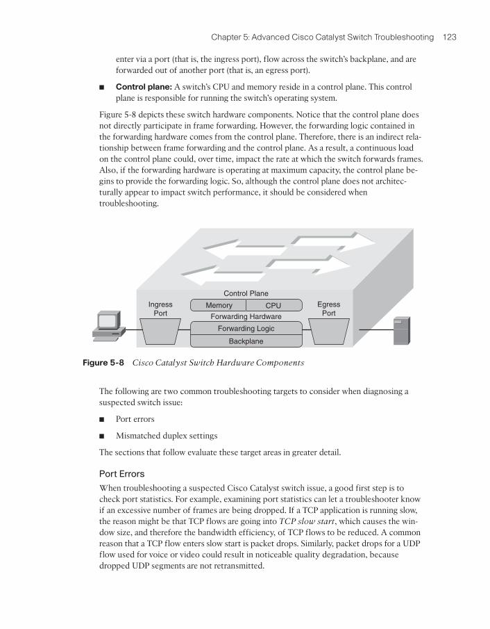
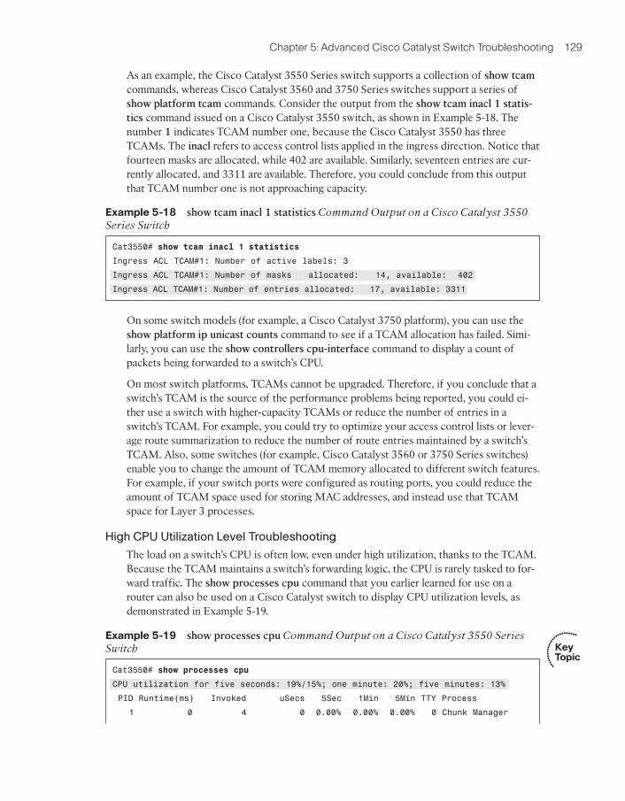
Cisco offers a variety of Catalyst switch platforms, with different port densities, differentlevels of performance, and different hardware. Therefore, troubleshooting one of theseswitches can be platform dependent. Many similarities do exist, however. For example, allCisco Catalyst switches include the following hardware components:
■ Ports: A switch’s ports physically connect the switch to other network devices.These ports (also known as interfaces) allow a switch to receive and transmit traffic.
■ Forwarding logic: A switch contains hardware that makes forwarding decisions.This hardware rewrites a frame’s headers.
■ Backplane: A switch’s backplane physically interconnects a switch’s ports. There-fore, depending on the specific switch architecture, frames flowing through a switch
Key Topic
Chapter 5: Advanced Cisco Catalyst Switch Troubleshooting 123
enter via a port (that is, the ingress port), flow across the switch’s backplane, and areforwarded out of another port (that is, an egress port).
■ Control plane: A switch’s CPU and memory reside in a control plane. This controlplane is responsible for running the switch’s operating system.
Figure 5-8 depicts these switch hardware components. Notice that the control plane doesnot directly participate in frame forwarding. However, the forwarding logic contained inthe forwarding hardware comes from the control plane. Therefore, there is an indirect rela-tionship between frame forwarding and the control plane. As a result, a continuous loadon the control plane could, over time, impact the rate at which the switch forwards frames.Also, if the forwarding hardware is operating at maximum capacity, the control plane be-gins to provide the forwarding logic. So, although the control plane does not architec-turally appear to impact switch performance, it should be considered whentroubleshooting.
The following are two common troubleshooting targets to consider when diagnosing asuspected switch issue:
■ Port errors
■ Mismatched duplex settings
The sections that follow evaluate these target areas in greater detail.
Port Errors
When troubleshooting a suspected Cisco Catalyst switch issue, a good first step is tocheck port statistics. For example, examining port statistics can let a troubleshooter knowif an excessive number of frames are being dropped. If a TCP application is running slow,the reason might be that TCP flows are going into TCP slow start, which causes the win-dow size, and therefore the bandwidth efficiency, of TCP flows to be reduced. A commonreason that a TCP flow enters slow start is packet drops. Similarly, packet drops for a UDPflow used for voice or video could result in noticeable quality degradation, becausedropped UDP segments are not retransmitted.
IngressPort
EgressPortForwarding Hardware
Forwarding Logic
Control Plane
Memory
Backplane
CPU
Figure 5-8 Cisco Catalyst Switch Hardware Components
124 CCNP TSHOOT 642-832 Official Certification Guide
Table 5-5 Errors in the show interfaces interface_id counters errors Command
Error Counter Description
Align-Err An alignment error occurs when frames do not end with an even number ofoctets, while simultaneously having a bad Cyclic Redundancy Check (CRC).An alignment error normally suggests a Layer 1 issue, such as cabling orport (either switch port or NIC port) issues.
FCS-Err A Frame Check Sequence (FCS) error occurs when a frame has an invalidchecksum, although the frame has no framing errors. Like the Align-Errerror, an FCS-Err often points to a Layer 1 issue.
Key Topic
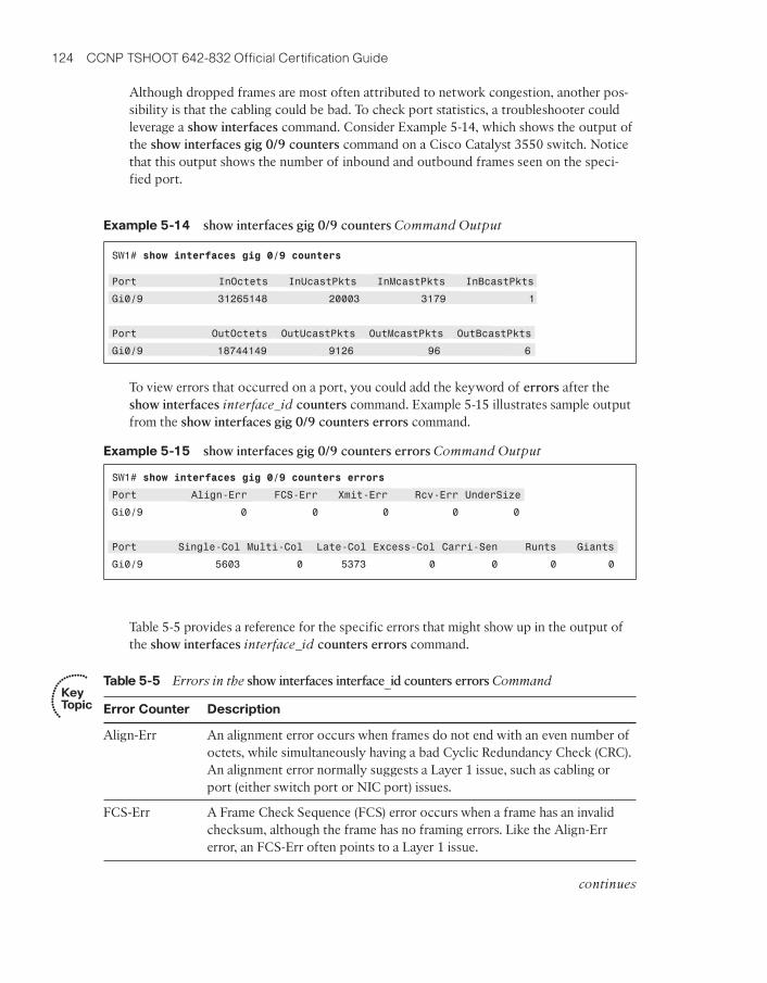
Although dropped frames are most often attributed to network congestion, another pos-sibility is that the cabling could be bad. To check port statistics, a troubleshooter couldleverage a show interfaces command. Consider Example 5-14, which shows the output ofthe show interfaces gig 0/9 counters command on a Cisco Catalyst 3550 switch. Noticethat this output shows the number of inbound and outbound frames seen on the speci-fied port.
Example 5-14 show interfaces gig 0/9 counters Command Output
To view errors that occurred on a port, you could add the keyword of errors after theshow interfaces interface_id counters command. Example 5-15 illustrates sample outputfrom the show interfaces gig 0/9 counters errors command.
Example 5-15 show interfaces gig 0/9 counters errors Command Output
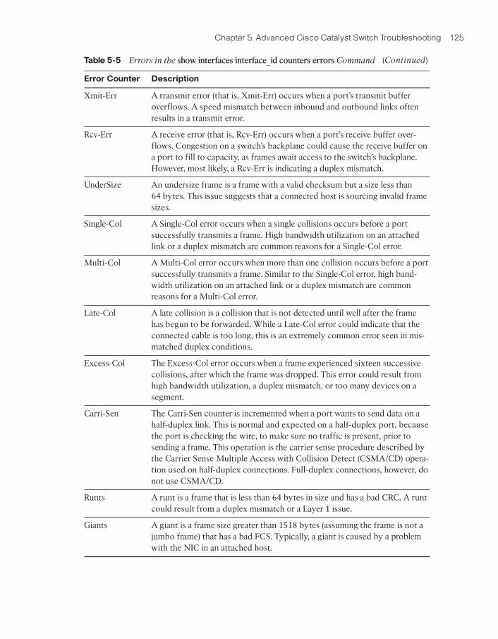
Table 5-5 provides a reference for the specific errors that might show up in the output ofthe show interfaces interface_id counters errors command.
SW1# show interfaces gig 0/9 counters
Port InOctets InUcastPkts InMcastPkts InBcastPkts
Gi0/9 31265148 20003 3179 1
Port OutOctets OutUcastPkts OutMcastPkts OutBcastPkts
Gi0/9 18744149 9126 96 6
SW1# show interfaces gig 0/9 counters errors
Port Align-Err FCS-Err Xmit-Err Rcv-Err UnderSize
Gi0/9 0 0 0 0 0
Port Single-Col Multi-Col Late-Col Excess-Col Carri-Sen Runts Giants
Gi0/9 5603 0 5373 0 0 0 0
continues
Chapter 5: Advanced Cisco Catalyst Switch Troubleshooting 125
Table 5-5 Errors in the show interfaces interface_id counters errors Command
Error Counter Description
Xmit-Err A transmit error (that is, Xmit-Err) occurs when a port’s transmit bufferoverflows. A speed mismatch between inbound and outbound links oftenresults in a transmit error.
Rcv-Err A receive error (that is, Rcv-Err) occurs when a port’s receive buffer over-flows. Congestion on a switch’s backplane could cause the receive buffer ona port to fill to capacity, as frames await access to the switch’s backplane.However, most likely, a Rcv-Err is indicating a duplex mismatch.
UnderSize An undersize frame is a frame with a valid checksum but a size less than 64 bytes. This issue suggests that a connected host is sourcing invalid framesizes.
Single-Col A Single-Col error occurs when a single collisions occurs before a portsuccessfully transmits a frame. High bandwidth utilization on an attachedlink or a duplex mismatch are common reasons for a Single-Col error.
Multi-Col A Multi-Col error occurs when more than one collision occurs before a portsuccessfully transmits a frame. Similar to the Single-Col error, high band-width utilization on an attached link or a duplex mismatch are commonreasons for a Multi-Col error.
Late-Col A late collision is a collision that is not detected until well after the framehas begun to be forwarded. While a Late-Col error could indicate that theconnected cable is too long, this is an extremely common error seen in mis-matched duplex conditions.
Excess-Col The Excess-Col error occurs when a frame experienced sixteen successivecollisions, after which the frame was dropped. This error could result fromhigh bandwidth utilization, a duplex mismatch, or too many devices on asegment.
Carri-Sen The Carri-Sen counter is incremented when a port wants to send data on ahalf-duplex link. This is normal and expected on a half-duplex port, becausethe port is checking the wire, to make sure no traffic is present, prior tosending a frame. This operation is the carrier sense procedure described bythe Carrier Sense Multiple Access with Collision Detect (CSMA/CD) opera-tion used on half-duplex connections. Full-duplex connections, however, donot use CSMA/CD.
Runts A runt is a frame that is less than 64 bytes in size and has a bad CRC. A runtcould result from a duplex mismatch or a Layer 1 issue.
Giants A giant is a frame size greater than 1518 bytes (assuming the frame is not ajumbo frame) that has a bad FCS. Typically, a giant is caused by a problemwith the NIC in an attached host.
(Continued)
126 CCNP TSHOOT 642-832 Official Certification Guide
SW1
Gig 0/9
Half-Duplex
Fa 5/47
Full-Duplex SW2
Figure 5-9 Topology with Duplex Mismatch
Mismatched Duplex Settings
As seen in Table 5-5, duplex mismatches can cause a wide variety of port errors. Keep inmind that almost all network devices, other than shared media hubs, can run in full-duplexmode. Therefore, if you have no hubs in your network, all devices should be running infull-duplex mode.
A new recommendation from Cisco is that switch ports be configured to autonegotiateboth speed and duplex. Two justifications for this recommendation are as follows:
■ If a connected device only supported half-duplex, it would be better for a switch portto negotiate down to half-duplex and run properly than being forced to run full-du-plex which would result in multiple errors.
■ The automatic medium-dependent interface crossover (auto-MDIX) feature can auto-matically detect if a port needs a crossover or a straight-through cable to intercon-nect with an attached device and adjust the port to work regardless of which cabletype is connected. You can enable this feature in interface configuration mode withthe mdix auto command on some models of Cisco Catalyst switches. However, theauto-MDIX feature requires that the port autonegotiate both speed and duplex.
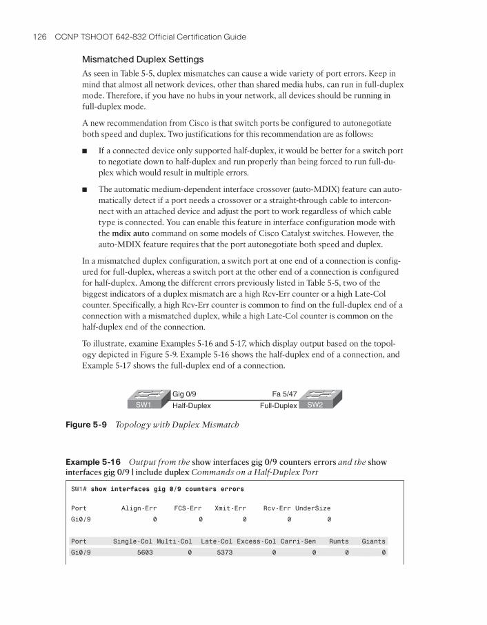
In a mismatched duplex configuration, a switch port at one end of a connection is config-ured for full-duplex, whereas a switch port at the other end of a connection is configuredfor half-duplex. Among the different errors previously listed in Table 5-5, two of thebiggest indicators of a duplex mismatch are a high Rcv-Err counter or a high Late-Colcounter. Specifically, a high Rcv-Err counter is common to find on the full-duplex end of aconnection with a mismatched duplex, while a high Late-Col counter is common on thehalf-duplex end of the connection.
To illustrate, examine Examples 5-16 and 5-17, which display output based on the topol-ogy depicted in Figure 5-9. Example 5-16 shows the half-duplex end of a connection, andExample 5-17 shows the full-duplex end of a connection.
Example 5-16 Output from the show interfaces gig 0/9 counters errors and the showinterfaces gig 0/9 | include duplex Commands on a Half-Duplex Port
SW1# show interfaces gig 0/9 counters errors
Port Align-Err FCS-Err Xmit-Err Rcv-Err UnderSize
Gi0/9 0 0 0 0 0
Port Single-Col Multi-Col Late-Col Excess-Col Carri-Sen Runts Giants
Gi0/9 5603 0 5373 0 0 0 0
Chapter 5: Advanced Cisco Catalyst Switch Troubleshooting 127
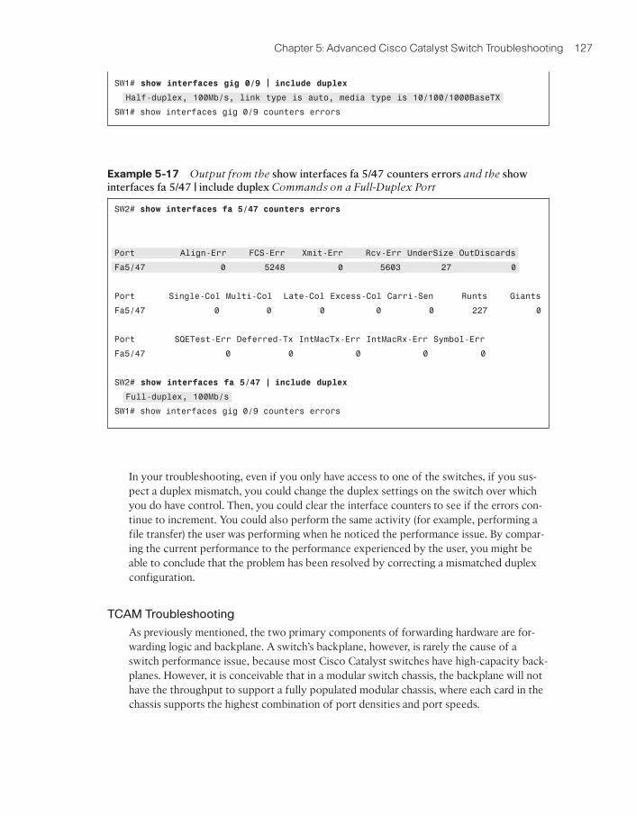
Example 5-17 Output from the show interfaces fa 5/47 counters errors and the showinterfaces fa 5/47 | include duplex Commands on a Full-Duplex Port
In your troubleshooting, even if you only have access to one of the switches, if you sus-pect a duplex mismatch, you could change the duplex settings on the switch over whichyou do have control. Then, you could clear the interface counters to see if the errors con-tinue to increment. You could also perform the same activity (for example, performing afile transfer) the user was performing when he noticed the performance issue. By compar-ing the current performance to the performance experienced by the user, you might beable to conclude that the problem has been resolved by correcting a mismatched duplexconfiguration.
TCAM Troubleshooting
As previously mentioned, the two primary components of forwarding hardware are for-warding logic and backplane. A switch’s backplane, however, is rarely the cause of aswitch performance issue, because most Cisco Catalyst switches have high-capacity back-planes. However, it is conceivable that in a modular switch chassis, the backplane will nothave the throughput to support a fully populated modular chassis, where each card in thechassis supports the highest combination of port densities and port speeds.
SW1# show interfaces gig 0/9 include duplex
Half-duplex, 100Mb/s, link type is auto, media type is 10/100/1000BaseTX
SW1# show interfaces gig 0/9 counters errors
SW2# show interfaces fa 5/47 counters errors
Port Align-Err FCS-Err Xmit-Err Rcv-Err UnderSize OutDiscards
Fa5/47 0 5248 0 5603 27 0
Port Single-Col Multi-Col Late-Col Excess-Col Carri-Sen Runts Giants
Fa5/47 0 0 0 0 0 227 0
Port SQETest-Err Deferred-Tx IntMacTx-Err IntMacRx-Err Symbol-Err
Fa5/47 0 0 0 0 0
SW2# show interfaces fa 5/47 include duplex
Full-duplex, 100Mb/s
SW1# show interfaces gig 0/9 counters errors
128 CCNP TSHOOT 642-832 Official Certification Guide
Control Plane
Routing Processes
Traffic PoliciesTCAM
Figure 5-10 Populating the TCAM
The architecture of some switches allows groups of switch ports to be handled by sepa-rated hardware. Therefore, you might experience a performance gain by simply moving acable from one switch port to another. However, to strategically take advantage of this de-sign characteristic, you must be very familiar with the architecture of the switch withwhich you are working.
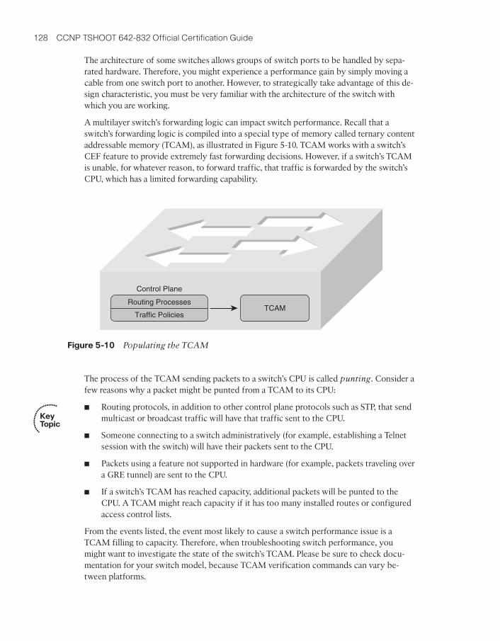
A multilayer switch’s forwarding logic can impact switch performance. Recall that aswitch’s forwarding logic is compiled into a special type of memory called ternary contentaddressable memory (TCAM), as illustrated in Figure 5-10. TCAM works with a switch’sCEF feature to provide extremely fast forwarding decisions. However, if a switch’s TCAMis unable, for whatever reason, to forward traffic, that traffic is forwarded by the switch’sCPU, which has a limited forwarding capability.
The process of the TCAM sending packets to a switch’s CPU is called punting. Consider afew reasons why a packet might be punted from a TCAM to its CPU:
■ Routing protocols, in addition to other control plane protocols such as STP, that sendmulticast or broadcast traffic will have that traffic sent to the CPU.
■ Someone connecting to a switch administratively (for example, establishing a Telnetsession with the switch) will have their packets sent to the CPU.
■ Packets using a feature not supported in hardware (for example, packets traveling overa GRE tunnel) are sent to the CPU.
■ If a switch’s TCAM has reached capacity, additional packets will be punted to theCPU. A TCAM might reach capacity if it has too many installed routes or configuredaccess control lists.
From the events listed, the event most likely to cause a switch performance issue is aTCAM filling to capacity. Therefore, when troubleshooting switch performance, youmight want to investigate the state of the switch’s TCAM. Please be sure to check docu-mentation for your switch model, because TCAM verification commands can vary be-tween platforms.
Key Topic
Chapter 5: Advanced Cisco Catalyst Switch Troubleshooting 129
As an example, the Cisco Catalyst 3550 Series switch supports a collection of show tcamcommands, whereas Cisco Catalyst 3560 and 3750 Series switches support a series ofshow platform tcam commands. Consider the output from the show tcam inacl 1 statis-tics command issued on a Cisco Catalyst 3550 switch, as shown in Example 5-18. Thenumber 1 indicates TCAM number one, because the Cisco Catalyst 3550 has threeTCAMs. The inacl refers to access control lists applied in the ingress direction. Notice thatfourteen masks are allocated, while 402 are available. Similarly, seventeen entries are cur-rently allocated, and 3311 are available. Therefore, you could conclude from this outputthat TCAM number one is not approaching capacity.
Example 5-18 show tcam inacl 1 statistics Command Output on a Cisco Catalyst 3550Series Switch
On some switch models (for example, a Cisco Catalyst 3750 platform), you can use theshow platform ip unicast counts command to see if a TCAM allocation has failed. Simi-larly, you can use the show controllers cpu-interface command to display a count ofpackets being forwarded to a switch’s CPU.
On most switch platforms, TCAMs cannot be upgraded. Therefore, if you conclude that aswitch’s TCAM is the source of the performance problems being reported, you could ei-ther use a switch with higher-capacity TCAMs or reduce the number of entries in aswitch’s TCAM. For example, you could try to optimize your access control lists or lever-age route summarization to reduce the number of route entries maintained by a switch’sTCAM. Also, some switches (for example, Cisco Catalyst 3560 or 3750 Series switches)enable you to change the amount of TCAM memory allocated to different switch features.For example, if your switch ports were configured as routing ports, you could reduce theamount of TCAM space used for storing MAC addresses, and instead use that TCAMspace for Layer 3 processes.
High CPU Utilization Level Troubleshooting
The load on a switch’s CPU is often low, even under high utilization, thanks to the TCAM.Because the TCAM maintains a switch’s forwarding logic, the CPU is rarely tasked to for-ward traffic. The show processes cpu command that you earlier learned for use on arouter can also be used on a Cisco Catalyst switch to display CPU utilization levels, asdemonstrated in Example 5-19.
Example 5-19 show processes cpu Command Output on a Cisco Catalyst 3550 SeriesSwitch Key
Topic
Cat3550# show tcam inacl 1 statistics
Ingress ACL TCAM#1: Number of active labels: 3
Ingress ACL TCAM#1: Number of masks allocated: 14, available: 402
Ingress ACL TCAM#1: Number of entries allocated: 17, available: 3311
Cat3550# show processes cpu
CPU utilization for five seconds: 19%/15%; one minute: 20%; five minutes: 13%
PID Runtime(ms) Invoked uSecs 5Sec 1Min 5Min TTY Process
1 0 4 0 0.00% 0.00% 0.00% 0 Chunk Manager

130 CCNP TSHOOT 642-832 Official Certification Guide
2 0 610 0 0.00% 0.00% 0.00% 0 Load Meter
3 128 5 25600 0.00% 0.00% 0.00% 0 crypto sw pk pro
4 2100 315 6666 0.00% 0.05% 0.05% 0 Check heaps
...OUTPUT OMITTED...
Notice in the output in Example 5-19 that the switch is reporting a 19 percent CPU load,with 15 percent of the CPU load used for interrupt processing. The difference betweenthese two numbers is 4, suggesting that 4 percent of the CPU load is consumed with con-trol plane processing.
Although such load utilization values might not be unusual for a router, these values mightbe of concern for a switch. Specifically, a typical CPU load percentage dedicated to inter-rupt processing is no more than five percent. A value as high as ten percent is consideredacceptable. However, the output given in Example 5-19 shows a fifteen percent utilization.Such a high level implies that the switch’s CPU is actively involved in forwarding packetsthat should normally be handled by the switch’s TCAM. Of course, this value might onlybe of major concern if it varies from baseline information. Therefore, your troubleshoot-ing efforts benefit from having good baseline information.
Periodic spikes in processor utilization are also not a major cause for concern if suchspikes can be explained. Consider the following reasons that might cause a switch’s CPUutilization to spike:
■ The CPU processing routing updates
■ Issuing a debug command (or other processor-intensive commands)
■ Simple Network Management Protocol (SNMP) being used to poll network devices
If you determine that a switch’s high CPU load is primarily the result of interrupts, youshould examine the switch’s packet switching patterns and check the TCAM utilization. If,however, the high CPU utilization is primarily the result of processes, you should investi-gate those specific processes.
A high CPU utilization on a switch might be a result of STP. Recall that an STP failurecould lead to a broadcast storm, where Layer 2 broadcast frames endlessly circulatethrough a network. Therefore, when troubleshooting a performance issue, realize that aswitch’s high CPU utilization might be a symptom of another issue.
Trouble Ticket: HSRP
This trouble ticket focuses on HSRP. HSRP was one of three first-hop redundancy proto-cols discussed in this chapter’s “Router Redundancy Troubleshooting” section.
Trouble Ticket #2
You receive the following trouble ticket:
A new network technician configured HSRP on routers BB1 and BB2, where BB1 wasthe active router. The configuration was initially working; however, now BB2 is actingas the active router, even though BB1 seems to be operational.

Chapter 5: Advanced Cisco Catalyst Switch Troubleshooting 131
S 1/0.2.1
Lo 010.3.3.3/32
Fa 0/0.1
S 1/0.2.1DLCI = 182
DLCI = 811
S 1/0.1.1
Lo 010.1.1.1/32
Lo 010.2.2.2/32
172.16.1.0/30
Fa 0/0
DLCI = 881FXS1/0/0.11
FXS1/0/1
R2
192.
168.
1.0/
24
192.168.0.0/24
.11Fa 0/1
172.16.2.0/30
S 1/0.1.2DLCI = 882
Fa 0/0.22
10.1
.3.0
/30
10.1
.2.0
/24
Gig 0/8 Fa 5/46
Lo 010.4.4.4/32
S 1/0.2.2
DLCI = 821 .2Fa 0/0
Gig 0/9 Fa 5/47Fa 5/45
x3333Gig 0/10 Fa 5/48
100 Mbps
10 Mbps
R1
BB2
BB1
FRSWR2
x2222x1111
SW2SW1
S 1/0.1.2DLCI = 181
Figure 5-11 Trouble Ticket #2 Topology
This trouble ticket references the topology shown in Figure 5-11.
As you investigate this issue, you examine baseline data collected after HSRP was initiallyconfigured. Examples 5-20 and 5-21 provide show and debug command output collectedwhen HSRP was working properly. Notice that router BB1 was acting as the active HSRProuter, whereas router BB2 was acting as the standby HSRP router.
Example 5-20 Baseline Output for Router BB1
BB1# show standby brief
P indicates configured to preempt.
Interface Grp Prio P State Active Standby Virtual IP
Fa0/1 1 150 Active local 172.16.1.3 172.16.1.4
BB1# debug standby
HSRP debugging is on
*Mar 1 01:14:21.487: HSRP: Fa0/1 Grp 1 Hello in 172.16.1.3 Standby pri 100 vIP172.16.1.4
*Mar 1 01:14:23.371: HSRP: Fa0/1 Grp 1 Hello out 172.16.1.1 Active pri 150 vIP172.16.1.4

132 CCNP TSHOOT 642-832 Official Certification Guide
Example 5-21 Baseline Output for Router BB2
BB2# show standby brief
P indicates configured to preempt.
BB1# u all
All possible debugging has been turned off
BB1# show standby fa 0/1 1
FastEthernet0/1 - Group 1
State is Active
10 state changes, last state change 00:12:40
Virtual IP address is 172.16.1.4
Active virtual MAC address is 0000.0c07.ac01
Local virtual MAC address is 0000.0c07.ac01 (v1 default)
Hello time 3 sec, hold time 10 sec
Next hello sent in 1.536 secs
Preemption disabled
Active router is local
Standby router is 172.16.1.3, priority 100 (expires in 9.684 sec)
Priority 150 (configured 150)
IP redundancy name is “hsrp-Fa0/1-1” (default)
BB1# show run
...OUTPUT OMITTED...
hostname BB1
!
interface Loopback0
ip address 10.3.3.3 255.255.255.255
!
interface FastEthernet0/0
ip address 10.1.2.1 255.255.255.0
!
interface FastEthernet0/1
ip address 172.16.1.1 255.255.255.0
standby 1 ip 172.16.1.4standby 1 priority 150
!
router ospf 1
network 0.0.0.0 255.255.255.255 area 0

Chapter 5: Advanced Cisco Catalyst Switch Troubleshooting 133
As part of testing the initial configuration, a ping was sent to the virtual IP address of172.16.1.4 from router R2 in order to confirm that HSRP was servicing requests for that IPaddress. Example 5-22 shows the output from the ping command.
Example 5-22 PINGing the Virtual IP Address from Router R2
As you begin to gather information about the reported problem, you reissue the showstandby brief command on routers BB1 and BB2. As seen in Examples 5-23 and 5-24,router BB1 is administratively up with an HSRP priority of 150, whereas router BB2 is ad-ministratively up with a priority of 100.
Example 5-23 Examining the HSRP State of Router BB1’s FastEthernet 0/1 Interface
Interface Grp Prio P State Active Standby Virtual IP
Fa0/1 1 100 Standby 172.16.1.1 local 172.16.1.4
BB2# show run
...OUTPUT OMITTED...
hostname BB2
!
interface Loopback0
ip address 10.4.4.4 255.255.255.255
!
interface FastEthernet0/0
ip address 10.1.2.2 255.255.255.0
!
interface FastEthernet0/1
ip address 172.16.1.3 255.255.255.0
standby 1 ip 172.16.1.4
!
router ospf 1
network 0.0.0.0 255.255.255.255 area 0
R2# ping 172.16.1.4
Type escape sequence to abort.
Sending 5, 100-byte ICMP Echos to 172.16.1.4, timeout is 2 seconds:
!!!!!
BB1# show standby brief
P indicates configured to preempt.
Interface Grp Prio P State Active Standby Virtual IP
Fa0/1 1 150 Standby 172.16.1.3 local 172.16.1.4

134 CCNP TSHOOT 642-832 Official Certification Guide
Example 5-24 Examining the HSRP State of Router BB2’s FastEthernet 0/1 Interface
Take a moment to look through the baseline information, the topology, and the showcommand output. Then, hypothesize the underlying cause, explaining why router BB2 iscurrently the active HSRP router, even thought router BB1 has a higher priority. Finally, on a separate sheet of paper, write out a proposed action plan for resolving the reportedissue.
Suggested Solution
Upon examination of BB1’s output, it becomes clear that the preempt feature is not en-abled for the Fast Ethernet 0/1 interface on BB1. The absence of the preempt feature ex-plains the reported symptom. Specifically, if BB1 had at one point been the active HSRProuter for HSRP group 1, and either router BB1 or its Fast Ethernet 0/1 interface becameunavailable, BB2 would have become the active router. Then, if BB1 or its Fast Ethernet 0/1interface once again became available, BB1 would assume a standby HSRP role, becauseBB1’s FastEthernet 0/1 interface was not configured for the preempt feature.
To resolve this configuration issue, the preempt feature is added to BB1’s Fast Ethernet 0/1interface, as shown in Example 5-25. After enabling the preempt feature, notice that routerBB1 regains its active HSRP role.
Example 5-25 Enabling the Preempt Feature on Router BB1’s FastEthernet 0/1 Interface
BB2# show standby brief
P indicates configured to preempt.
Interface Grp Prio P State Active Standby Virtual IP
Fa0/1 1 100 Active local 172.16.1.1 172.16.1.4
BB1# conf term
Enter configuration commands, one per line. End with CNTL/Z.
BB1(config)#int fa 0/1
BB1(config-if)#standby 1 preempt
BB1(config-if)#end
BB1#
*Mar 1 01:17:39.607: %HSRP-5-STATECHANGE: FastEthernet0/1 Grp 1 state Standby ->Active
BB1#show standby brief
P indicates configured to preempt.
Interface Grp Prio P State Active Standby Virtual IP
Fa0/1 1 150 P Active local 172.16.1.3 172.16.1.4

Chapter 5: Advanced Cisco Catalyst Switch Troubleshooting 135
Table 5-6 Key Topics for Chapter 5
Key Topic
Element
Description Page
Number
Table 5-2 Similarities and differences between routers and Layer 3switches
Table 5-3 Router data plane verification commands
Example 5-3 SVI configuration
List Differences between SVIs and routed ports
Examples 5-5and 5-6
HSRP configuration
Figure 5-6 Basic VRRP Operation
Figure 5-7 Basic GLBP Operation
Table 5-4 Comparing HSRP, VRRP, and GLBP
List Cisco Catalyst hardware components 122
Table 5-5 Errors in the show interfaces interface_id counters errorscommand
List Reasons why a packet might be punted from a TCAM to itsCPU
Example 5-19 Output from the show processes cpu command on a CiscoCatalyst 3550 Series switch
Exam Preparation Tasks
Review All Key Topics
Review the most important topics from inside the chapter, noted with the Key Topics iconin the outer margin of the page. Table 5-6 lists these key topics and the page numberswhere each is found.
Complete Tables and Lists from Memory
Print a copy of Appendix B, “Memory Tables,” (found on the CD) or at least the sectionfor this chapter, and complete the tables and lists from memory. Appendix C, “Memory Ta-bles Answer Key,” also on the CD, includes completed tables and lists to check your work.
Key Topic
111
112
113
115
116
121
121
122
124
128
129

136 CCNP TSHOOT 642-832 Official Certification Guide
Table 5-7 Chapter 5 Configuration Command Reference
Command Description
standby group ip virtual-ip-
address
Interface configuration mode command, used to spec-ify the virtual IP address to be serviced by an HSRPgroup.
standby group priority priority Interface configuration mode command, used to con-figure an interface’s HSRP priority (which defaults to100).
standby group preempt Interface configuration mode command, which causesa previously active HSRP router to regain its active sta-tus if it becomes available.
mdix auto Interface configuration mode command for a switchthat allows the switch port to automatically detect andadjust to the connected cable type (that is, eitherstraight-through or cross-over).
Define Key Terms
Define the following key terms from this chapter, and check your answers in the Glossary:
Layer 3 switch, switched virtual interface (SVI), Hot Standby Router Protocol (HSRP), Vir-tual Router Redundancy Protocol (VRRP), Global Load Balancing Protocol (GLBP), con-trol plane, backplane, Ternary Content Addressable Memory (TCAM)
Command Reference to Check Your Memory
This section includes the most important configuration and EXEC commands covered inthis chapter. To determine how well you have memorized the commands as a side effect ofyour other studies, cover the left side of Tables 5-7 and 5-8 with a piece of paper, read thedescriptions on the right side, and see whether you remember the command.

Chapter 5: Advanced Cisco Catalyst Switch Troubleshooting 137
Table 5-8 Chapter 5 EXEC Command Reference
Command Description
show standby interface-id group Displays the HSRP configuration applied to a speci-fied interface in a specified HSRP group.
show standby brief Provides a summary view of a router’s HSRPconfiguration.
debug standby Shows HSRP state changes and information aboutsent and received HSRP packets.
show vrrp brief Provides a summary view of a router’s VRRPconfiguration.
show glbp brief Provides a summary view of a router’s GLBPconfiguration.
show ip cef Displays the router’s Layer 3 forwarding informa-tion, in addition to multicast, broadcast, and local IPaddresses.
show adjacency Verifies that a valid adjacency exists for a connectedhost.
show tcam inacl tcam_number
statisticsA Cisco Catalyst 3550 Series switch command thatdisplays the amount of TCAM memory allocatedand used for inbound access control lists.
show platform ip unicast counts A Cisco Catalyst 3750 Series switch command thatcan be used to see if a TCAM allocation has failed.
show controllers cpu-interface A Cisco Catalyst 3750 Series switch command thatcan be used to display a count of packets being for-warded to a switch’s CPU.

Numerics
2-Way adjacency state, 177
3-Way adjacency state, 177
A
AAA, configuring, 285–288
ABRs, 172–173
accessing data plane, 270–272
accounting management, 9
AD (advertised distance), 153
address format, IPv6, 378–379
adjacencies, 152
forming, 176–177
adjacency table, 111–113, 144
administrative distance, 151
advertisements, tracking through anetwork, 177–178
anycast addresses, 377–378
application performance, optimizingwith IP SLAs, 423–429
application servers, 331
ARP spoofing, 276–277
AS (autonomous system), 227
ASA (Adaptive Security Appliance), 277
ASBRs (autonomous system borderrouters), 172–173
Attempt adjacency state, 177
AutoQoS, 341–346
AutoQoS Enterprise, configuring,432–434
availability, five nines, 90
AVFs (active virtual forwarders), 121
B
backbone routers (OSPF), 172–173
backup tools, 16–19
baselines, 424–426
creating
with NetFlow, 67–68
with SNMP, 66–67
establishing, 45
basic network maintenance tools, 14
basic routing
troubleshooting, 144–149
BDRs (backup designated routers), 171
BEE (Boson Exam Environment), 473
installing, 474
believability of routing protocols, 151
best route selection, EIGRP, 153–154
BGP, 227–244
AS, 227
data structures, 227–230
excessive CPU utilization
troubleshooting, 245–251
packet forwarding decision process, 229
trouble ticket, 236–245
troubleshooting commands, 229–236
Index

498 BGP table
BGP table, 228
bootup process for Cisco IP Phones,334–335
bottom-up troubleshooting method,35–36
boundary routers, 205
broadcast storms, troubleshooting, 95–96
buffer leaks, 259–260
C
call agents, 331
capturing packets, 62–66
case studies, troubleshooting complexnetworks, 464–469
CCNP Prep Center, 475
CD, installing, 474
CEF, 144, 252–254
CEF (Cisco Express Forwarding),111–113
change management, 11–12
role in troubleshooting procedure, 46–47
Cisco ANS (Application NetworkService)
application optimization, 423–424
components of, 422–423
QoS, configuring, 432–434
troubleshooting, 422–434
Cisco Catalyst switches, 127–129
performance, troubleshooting, 122–130
high CPU utilization, 129–130
mismatched duplex settings,126–127
port errors, 123–125
troubleshooting commands, 88–90
Cisco IOS Firewall, configuring, 281–285
Cisco IOS Software
diagnostic tools, filtering showcommand output, 53–57
IP SLA feature, application perform-ance, 426–429
NAC feature, 280
security trouble ticket, 288–294
uRPF (Unicast Reverse PathForwarding), 279
Cisco IP Phones, bootup process,334–335
Cisco Lifecycle Services, 8
Cisco SONA (Service-Oriented NetworkArchitecture), 422
Cisco support tools, 21
Cisco TelePresence, 348
Cisco Unified Video Advantage, 348
Cisco Unified Wireless Networkarchitecture, 435–437
split-MAC mode, 435–436
supported EAP types, 437
CLI tools, 14–15
collecting information, 40
collecting STP topology information,93–94
commands, 57–58
debug ip dhcp server events, 316
debug ip eigrp, 158
debug ip ospf adj, 184
debug ip ospf events, 185
debug ip ospf packet, 184
debug ip routing, 183
debug ip routing command, 234
DHCP, troubleshooting, 314–317
EIGRP, troubleshooting, 154–158
NAT, troubleshooting, 306–309
ping, 58–60
show commands, filtering output,53–57
show ip bgp, 233–234
show ip bgp neighbors, 231–233
show ip bgp summary, 231
show ip cef, 112–113

debug ip ospf packet command 499
show ip dhcp binding, 316
show ip dhcp conflict, 315–316
show ip ospf database, 181
show ip ospf interface brief, 180
show ip ospf monitor, 182
show ip ospf neighbor, 181
show ip ospf statistics, 181–182
show ip ospf virtual-links, 185–186
show ip route bgp, 234–235
show ip route eigrp, 156
show ip route ospf, 183
show memory allocating-process totals, 260
show spanning-tree interface, 94
communicating through thetroubleshooting process, 45–46
comparing
configurations as troubleshootingmethod, 36–37
Layer 3 switches and routers, 110–111
routed switch ports and switched virtualinterfaces, 113–115
complex networks
troubleshooting
case study, 464–469
prerequisites for, 464
complex networks, troubleshooting,463–469
component swapping as troubleshootingmethod, 37–38
configuration management, 9
configurations, comparing astroubleshooting method, 36–37
configuring
AAA, 285–288
AutoQoS Enterprise, 432–434
Cisco IOS Firewall, 281–285
EEM, 71–72
IP services, DHCP, 310–312
IPv6 support, 379–380
OSPFv3, 382–384
QoS
AutoQoS, 341–346
MQC, 336–341
RADIUS, 287–288
TACACS+ server, 286–288
connectivity, troubleshooting, 58–60
control plane, 111–113
DHCP, security, 274–276
securing, 272–277
STP, security, 273–274
cost metric (OSPF), 171
creating problem reports
hypothesis, verifying, 42–43
information, collecting, 40
information, examining, 40–41
problem resolution, 43
underlying causes of problems, 42
D
DAI (Dynamic ARP Inspection),276–277
data plane, 111–113
accessing, 270–272
securing, 277
security, 277–280
data structures
BGP, 227–230
EIGRP, 152
OSPF, 170–171
of routing protocols, 150–152
Dead timer (OSPF), 176
debug ip dhcp server events command, 316
debug ip eigrp command, 158
debug ip ospf adj command, 184
debug ip ospf events command, 185
debug ip ospf packet command, 184

500 debug ip routing command
debug ip routing command, 183, 234
default gateways, 115
defining troubleshooting, 31–33
design considerations
for video traffic, 348–349
for voice networks, 331–334
high availability, 332
QoS, 331–332
security, 332
DHCP
configuring, 310–312
message types, 311
security, 274–276
troubleshooting, 309–317
troubleshooting commands, 314–317, 439
in wireless networks, 438–439
diagnosing problems, 32–33
diagnostic tools
show command output, filtering, 53–57
specialized tools, 61–62
distribution trees, 353–354
divide-and-conquer troubleshootingmethod, 36
documentation
maintaining, 44–45
network maintenance, 12–13
DoS attacks, securing against, 277
Down adjacency state, 177
DRs (designated routers), 171
Dynamic NAT, 302
E
EAP, support for on Cisco UnifiedWireless Network architecture, 437
EEM, configuring, 71–72
EIGRP
best route selection, 153–154
data structures, 152
route redistribution with OSPF
troubleshooting, 209–220
trouble tickets, 158–162
troubleshooting, 149–162
troubleshooting commands, 154–158
variance feature, 153
eliminating potential causes of problems,41–42
enabling SNMP traps, 70–72
enterprise networks, troubleshooting
complex networks, 463–469
remote office networks, 448–462
establishing
baselines, 45
OSPF adjacencies, 176–177
EtherChannel, troubleshooting, 96–97
exam, 473
passing scores, 477
preparing for, 476
Exam Engine mode, selecting, 476–477
examining problem report information,40–41
excessive CPU utilization, troubleshoot-ing BGP, 245–251
excessive memory use, troubleshooting, 261
Exchange adjacency state, 177
ExStart adjacency state, 177
external routes, 206
F
failed devices, restoring, 13
fast switching, CEF, 252–254
fault management, 9
IPv6 501
FCAPS, 8, 9
FD (feasible distance), 153
FIB, 111–113, 144
filtering show command output, 53–57
firewalls
ASA (Adaptive Security Appliance), 277
Cisco IOS Firewall, configuring,281–285
data plane, securing, 277–280
first-hop redundancy protocols, 115
five nines availability, 90
flood-and-prune behavior (PIM-DM), 356
following the traffic path as trou-bleshooting method, 36
forwarding information, troubleshooting,145–148
Full Adjacency state, 177
G
gatekeepers, 331
gateways, 331
GLBP, 120–121
GLBP groups, 121
globally scoped addresses, 352
GLOP addresses, 352
GRE (Generic Routing Encapsulation),troubleshooting VPNs, 455–463
GUI tools, 15
H
H.323 video conferencing system, 348
hardware, troubleshooting, 60–61
Hello timer (OSPF), 176
high CPU utilization on Cisco Catalystswitches, troubleshooting, 129–130
HSRP, 116–120
trouble ticket, 130–134
hypotheses, verifying, 42–43
hypothesizing underlying causes ofproblems, 42
I
IGMP, 349–352
incident recovery tools, 22
Init adjacency state, 177
installing
BEE (Boson Exam Environment), 474
Practice Exam, 474–475
internal routers (OSPF), 172–173
internal routes, 206
interrupt driven tasks, 8
IP phones, 330
IP routing protocols, data structures,150–152
IP services
DHCP
configuring, 310–312
message types, 311
troubleshooting, 309–317
troubleshooting commands,314–317
NAT
incompatible applications, 305
order of interface operations,305–306
trouble ticket, 317–321
troubleshooting, 302–309
IP SLAs, optimizing applicationperformance, 426–429
IP Telephony, 330–331
IPSec VPNs, troubleshooting, 455–463
IPv4, tunneling IPv6, 380–382
IPv6
address format, 378–379
anycast addresses, 377–378

502 IPv6
multicast addresses, 376–377
routing options, 379
support, configuring, 379–380
tunneling through IPv4, 380–382
unicast addresses, 376
ITIL, 8
J-K-L
join messages, 356
Layer 2 switching, 81–88
STP, troubleshooting, 90–102
broadcast storms, 95–96
EtherChannel, 96–97
MAC address table corruption, 95
nonroot bridges, 91
root bridges, 91
trouble ticket, 97–102
troubleshooting, 88–90
Layer 3
basic routing, troubleshooting methods,144–149
forwarding information,troubleshooting, 145–148
Layer 2 mappings, troubleshooting, 148–149
troubleshooting, 141–149
Layer 3 switching, 110
control plane, 111–113
data plane, 111–113
versus routers, 110–111
lightweight access points, 435
limited scope addresses, 352
Loading adjacency state, 177
logging tools, 19–20
LSAs, 173–175
M
MAC address table corruption,troubleshooting, 95
maintaining network documentation,44–45
management plane, securing, 270–272
managing network changes, 11–12
man-in-the-middle attacks, 276
mapping OSI layers to networktechnologies, 463
MCU (Multipoint Control Unit), 331
measuring performance, 14
measuring tools, 22
memory
routers, troubleshooting, 258–261
TCAM, 113
Cisco Catalyst switches,troubleshooting, 127–129
punting, 128
memory allocation failures, 259
memory tables, 402–413
message types, DHCP, 311
metrics
cost, 171
seed metric, 205–206
mismatched duplex settings,troubleshooting Cisco Catalystswitches, 126–127
monitoring tools, 22
MQC (Modular Quality of ServiceCommand Line), 336–341
multicast addresses (IPv6), 376–377
multicasting, 349–357
addressing, 352–353
distribution trees, 353–354
IGMP, 349–352
PIM-DM, 354–356
PIM-SM, 356–357
multilayer switches, 110

OSPF 503
N
NAC (Network Admission Control)feature, Cisco IOS Software, 280
NAT
incompatible applications, 305
order of interface operations, 305–306
trouble ticket, 317–321
troubleshooting, 302–309
troubleshooting commands, 306–309
NAT Overloading, 302
NBAR, enabling protocol discovery,429–431
neighbor tables (BGP), 228
NetFlow
application performance, baselining,424–426
baselines, creating, 67–70
NetFlow collector, 424
network changes, managing, 11–12
network documentation tools, 21–22
network maintenance
documentation, 12–13, 44–45
failed devices, restoring, 13
models, 8–9
network changes, managing, 11–12
performance, measuring, 14
proactive versus reactive, 7–8
relationship to troubleshooting, 43–44
required network maintenance tools
backup tools, 16–19
Cisco support tools, 21
incident recovery tools, 22
logging tools, 19–20
monitoring tools, 22
network documentation tools,21–22
NTP, 20–21
routine tasks, 10
scheduled maintenance, 10
tool requirements
basic tools, 14
CLI tools, 14–15
GUI tools, 15
network security, 280–288
AAA, configuring, 285–288
network types (OSPF), 175–176
network unification, 435
nonroot bridges, 91
notifications for network events, 70–72
NTP (Network Time Protocol), 20–21
O
optimizing application performance,423–429
OSI layers, mapping to networktechnologies, 463
OSPF, 172–173
ABRs, 172–173
adjacencies, forming, 176–177
advertisements, tracking through anetwork, 177–178
ASBRs, 172–173
cost metric, 171
data structures, 170–171
designated routers, 171
LSA types, 173–175
network types, 175–176
route redistribution
with OSPF, troubleshooting,209–220
troubleshooting, 204–209
route redistribution, troubleshooting
seed metric, 205–206
targets, 206–209
timers, 176

504 OSPFv3
trouble ticket, 186–204
troubleshooting commands, 178–186
OSPFv3
configuring, 382–384
troubleshooting, 384–399
Overlapping NAT, 302
P
packet captures, performing, 62–66
packet forwarding decision process(BGP), 229
packet switching modes, 254–258
passing scores for exam, 477
PBX systems, 330
performance
of applications, baselining, 424–426
of applications, optimizing, 423–424
with IP SLAs, 426–429
BGP, troubleshooting excessive CPUutilization, 245–251
Cisco Catalyst switches, 122–130
mismatched duplex settings,troubleshooting, 126–127
port errors, 123–125
Cisco Catalyst switches,troubleshooting
high CPU utilization, 129–130
TCAM, 127–129
performance, measuring, 14
performance management, 9
performing packet captures, 62–66
PIM-DM, 354–356
PIM-SM, 356–357
ping command, troubleshootingconnectivity, 58–60
PoE, effect on wireless networks, 437–438
port errors, troubleshooting CiscoCatalyst switches, 123–125
ports, STP, 91–93
potential causes of problems,eliminating, 41–42
Practice Exam, installing, 474–475
preparing for exam, 476
prerequisites for troubleshootingcomplex networks, 464
preventing man-in-the-middle attacks, 279
proactive versus reactive networkmaintenance, 7–8
problem reports, creating
hypothesis, verifying, 42–43
information, collecting, 40
information, examining, 40–41
potential causes, eliminating, 41–42
problem resolution, 43
underlying cause, hypothesizing, 42
problems, diagnosing, 32–33
process switching, 251–252
protocol discovery (NBAR), enabling,429–431
PSTN, 331
punting, 128
Q
QoS, 336–346
AutoQoS, 341–346
AutoQoS Enterprise, configuring,432–434
MQC, 336–341
in voice networks, 331–332
in wireless networks, 439
R
RADIUS, configuring, 287–288
reactive versus proactive networkmaintenance, 7–8
routing protocols 505
recognizing
application traffic with NBAR, 429–431
redirecting show command output to afile, 57–58
redundancy
HSRP trouble ticket, 130–134
routers, 115–122
GLBP, 120–121
HSRP, 116–120
VRRP, 120–121
relationship between networkmaintenance and troubleshooting,43–44
remote office networks, troubleshooting,448–462
remote-access VPNs, troubleshooting,453–454
site-to-site VPNs, troubleshooting,449–453
remote-access VPNs, troubleshooting,453–454
rendezvous points, 357
required network maintenance tools
backup tools, 16–19
basic tools, 14
Cisco support tools, 21
CLI tools, 14–15
GUI tools, 15
incident recovery tools, 22
logging tools, 19–20
monitoring tools, 22
network documentation tools, 21–22
NTP, 20–21
reserve local link addresses, 352
resolving problems, 43
restoring failed devices, 13
RIPng
trouble ticket, 402–413
troubleshooting, 399–402
role of communication introubleshooting process, 45–46
root bridges, 91
route redistribution
OSPF, troubleshooting, 204–209
OSPF with EIGRP, 209–220
routed switch ports, versus switchedvirtual interfaces, 113–115
router on a stick, 110
routers
control plane, 111–113
data plane, 111–113
versus Layer 3 switches, 110–111
memory, troubleshooting, 258–261
packet switching modes, 254–258
redundancy, 115–122
GLBP, 121–122
HSRP, 116–120
VRRP, 120–121
routine maintenance tasks, 10
routing, troubleshooting, 144–149
routing options (IPv6), 379
routing processes, 141–144
routing protocols
adjacencies, 152
administrative distance, 151
believability, 151
data structures, 150–152
EIGRP
best route selection, 153–154
data structures, 152
route redistribution with OSPF,troubleshooting, 209–220
trouble tickets, 158–162
troubleshooting, 149–162
troubleshooting commands,154–158
variance feature, 153

506 routing protocols
OSPF
ABRs, 172–173
adjacencies, forming, 176–177
ASBRs, 172–173
backbone routers, 172–173
data structures, 170–171
designated routers, 171
internal routers, 172–173
LSAs, 173–175
network types, 175–176
route redistribution,troubleshooting, 204–209
route redistribution with EIGRP,troubleshooting, 209–220
timers, 176
trouble ticket, 186–204
troubleshooting commands,178–186
OSPFv3, troubleshooting, 384–399
RIPng
trouble ticket, 402–413
troubleshooting, 399–402
RSPAN, packet captures, 64–66
S
scheduled maintenance, 10
security
Cisco IOS Software, trouble ticket,288–294
control plane, 272–277
DHCP, 274–276
STP, 273–274
data plane, 277–280
management plane, 270–272
network security, 280–288
for voice networks, 332
in wireless networks, 438
security management, 9
seed metric, 205–206
selecting
Exam Engine mode, 476–477
network maintenance model, 8–9
troubleshooting methods, 38–39
services for voice networks, 332–333
shared distribution trees, 354
shoot from the hip troubleshootingapproach, 33–34
show command output
filtering, 53–57
redirecting to a file, 57–58
show ip bgp command, 233–234
show ip bgp neighbors command,231–233
show ip bgp summary command, 231
show ip cef command, 112–113
show ip dhcp binding command, 316
show ip dhcp conflict command,315–316
show ip ospf database command, 181
show ip ospf interface brief command, 180
show ip ospf monitor command,182–183
show ip ospf neighbor command, 181
show ip ospf statistics command,181–182
show ip ospf virtual-links command,185–186
show ip route bgp command, 234–235
show ip route eigrp command, 156
show ip route ospf command, 183
show memory allocating-process totalscommand, 260
show spanning-tree interface command, 94
simplified troubleshooting model, 32
Simulation Mode (Exam Engine), 476

troubleshooting methods 507
site-to-site VPNs, troubleshooting,449–453
SNMP
baselines, creating, 66–67
data plane, accessing, 272
network events, notifications, 70–72
traps, 70–72
source distribution trees, 353–354
Spanning Tree Protocol
broadcast storms, troubleshooting,95–96
EtherChannel, troubleshooting, 96–97
MAC address table corruption,troubleshooting, 95
nonroot bridges, 91
ports, 91–93
root bridges, 91
security, 273–274
topology information, collecting, 93–94
trouble ticket, 97–102
troubleshooting, 90–102
specialized tools, 61–62
split-MAC mode (Cisco Unified WirelessNetwork architecture), 435–436
SSM addresses, 352
static NAT, 302
structured tasks, 7–8
structured troubleshooting approach,33–34
Study Mode (Exam Engine), 476
subprocesses of troubleshootingprocedures, 39–40
SVIs (switched virtual interfaces),113–115
swapping components astroubleshooting method, 37–38
switched virtual interfaces, versusrouted switch ports, 113–115
T
TACACS+ server, configuring, 286–288
TCAM (Ternary Content AddressableMemory), 113
Cisco Catalyst switches,troubleshooting, 127–129
punting, 128
TCP slow start, 123
timers (OSPF), 176
TMN, 8
top-down troubleshooting method,34–35
tracking adjacencies through a network,177–178
traps (SNMP), enabling, 70–72
trouble tickets
BGP, 236–245
Cisco IOS Software, 288–294
EIGRP, 158–162
HSRP, 130–134
NAT, 317–321
OSPF, 186–204
OSPFv3, troubleshooting, 384–399
RIPng, 402–413
STP, troubleshooting, 97–102
Unified Communications, 359–369
troubleshooting
hardware, 60–61
IP services
DHCP, 309–317
NAT, 302–309
video traffic, 346–358
troubleshooting commands
BGP, 229–236
OSPF, 178–186
troubleshooting methods
bottom-up method, 35–36
component swapping, 37–38
508 troubleshooting methods
configurations, comparing, 36–37
divide-and-conquer method, 36
following the traffic path, 36
selecting, 38–39
subprocesses, 39–40
top-down method, 34
troubleshooting process
change management, 46–47
communication, importance of, 45–46
tunneling IPv6 through IPv4, 380–382
Type 1 LSAs, 174–175
Type 2 LSAs, 174–175
Type 3 LSAs, 174–175
Type 4 LSAs, 174–175
Type 5 LSAs, 174–175
Type 6 LSAs, 174–175
Type 7 LSAs, 174–175
U-V
unicast addresses, 376
Unified Communications, trouble tickets,359–369
uRPF (Unicast Reverse PathForwarding), 279
variance feature (EIGRP), 153
verifying hypotheses, 42–43
video traffic, 346–358
design considerations, 348–349
IP-based video, 347–348
multicasting, 349–357
addressing, 352–353
distribution trees, 353–354
IGMP, 349–352
PIM-DM, 354–356
PIM-SM, 356–357
troubleshooting targets, 358
videoconference stations, 331
VLANs
effect on wireless networks, 438
Layer 2 switching, 81–88
voice networks
Cisco IP Phones, bootup process,334–335
design considerations, 331–334
high availability, 332
QoS, 331–332
security, 332
IP Telephony, 330–331
QoS, 336–346
MQC, 336–341
services, 332–333
troubleshooting targets, 335
Unified Communications, troubletickets, 359–369
VoIP, 330
VPNs, troubleshooting
IPSec, 455–463
remote-access, 453–454
site-to-site, 449–453
VRRP, 120–121
W-X-Y-Z
web access (data plane), 271–272
wedged interfaces, 260
wireless networks
Cisco Unified Wireless Networkarchitecture, 435–437
DHCP, 438–439
PoE, 437–438
QoS, 439
troubleshooting, 434–439
VLANs, 438
WLANs, troubleshooting, 435–439