ccna semester 1 labs - it collegeenos.itcollege.ee/~truls/labs/newccnasem1/sem1_batch2.pdf8.1.4.6...
TRANSCRIPT

CCNA Semester 1 labs
Part 2 of 2
Labs for chapters 8 – 11

8.1.4.6 Lab - Calculating IPv4 Subnets
8.1.4.8 Lab - Designing and Implementing a Subnetted IPv4 Addressing Scheme
8.2.1.5 Lab - Designing and Implementing a VLSM Addressing Scheme
9.2.1.6 Lab - Using Wireshark to Observe the TCP 3-Way Handshake
9.2.4.3 Lab - Using Wireshark to Examine TCP and UDP Captures
10.2.2.8 Lab - Observing DNS Resolution
11.2.4.7 Lab - Examining Telnet and SSH in Wireshark
11.2.4.8 Lab - Securing Network Devices
11.3.4.6 Lab - Using the CLI to Gather Network Device Information

© 2016 Cisco and/or its affiliates. All rights reserved. This document is Cisco Public. Page 1 of 7
Lab Calculating IPv4 Subnets
Objectives
Part 1: Determine IPv4 Address Subnetting
Part 2: Calculate IPv4 Address Subnetting
Background / Scenario
The ability to work with IPv4 subnets and determine network and host information based on a given IP address and subnet mask is critical to understanding how IPv4 networks operate. The first part is designed to reinforce how to compute network IP address information from a given IP address and subnet mask. When given an IP address and subnet mask, you will be able to determine other information about the subnet.
Required Resources
1 PC (Windows 7 or 8 with Internet access)
Optional: IPv4 address calculator
Part 1: Determine IPv4 Address Subnetting
In Part 1, you will determine the network and broadcast addresses, as well as the number of hosts, given an IPv4 address and subnet mask.
REVIEW: To determine the network address, perform binary ANDing on the IPv4 address using the subnet mask provided. The result will be the network address. Hint: If the subnet mask has decimal value 255 in an octet, the result will ALWAYS be the original value of that octet. If the subnet mask has decimal value 0 in an octet, the result will ALWAYS be 0 for that octet.
Example:
IP Address 192.168.10.10
Subnet Mask 255.255.255.0
==========
Result (Network) 192.168.10.0
Knowing this, you may only have to perform binary ANDing on an octet that does not have 255 or 0 in its subnet mask portion.
Example:
IP Address 172.30.239.145
Subnet Mask 255.255.192.0
Analyzing this example, you can see that you only have to perform binary ANDing on the third octet. The first two octets will result in 172.30 due to the subnet mask. The fourth octet will result in 0 due to the subnet mask.
IP Address 172.30.239.145
Subnet Mask 255.255.192.0
==========
Result (Network) 172.30.?.0
Perform binary ANDing on the third octet.

Lab Calculating IPv4 Subnets
© 2016 Cisco and/or its affiliates. All rights reserved. This document is Cisco Public. Page 2 of 7
Decimal Binary
239 11101111
192 11000000
=======
Result 192 11000000
Analyzing this example again produces the following result:
IP Address 172.30.239.145
Subnet Mask 255.255.192.0
==========
Result (Network) 172.30.192.0
Continuing with this example, determining the number of hosts per network can be calculated by analyzing the subnet mask. The subnet mask will be represented in dotted decimal format, such as 255.255.192.0, or in network prefix format, such as /18. An IPv4 address always has 32 bits. Subtracting the number of bits used for the network portion (as represented by the subnet mask) gives you the number of bits used for hosts.
Using our example above, the subnet mask 255.255.192.0 is equivalent to /18 in prefix notation. Subtracting 18 network bits from 32 bits results in 14 bits left for the host portion. From there, it is a simple calculation:
2(number of host bits) - 2 = Number of hosts
214 = 16,384 2 = 16,382 hosts
Determine the network and broadcast addresses and number of host bits and hosts for the given IPv4 addresses and prefixes in the following table.
IPv4 Address/Prefix Network Address Broadcast Address
Total Number of Host Bits
Total Number of Hosts
192.168.100.25/28
172.30.10.130/30
10.1.113.75/19
198.133.219.250/24
128.107.14.191/22
172.16.104.99/27
Part 2: Calculate IPv4 Address Subnetting
When given an IPv4 address, the original subnet mask and the new subnet mask, you will be able to determine:
Network address of this subnet
Broadcast address of this subnet
Range of host addresses of this subnet
Number of subnets created
Number of hosts per subnet
Lab Calculating IPv4 Subnets
© 2016 Cisco and/or its affiliates. All rights reserved. This document is Cisco Public. Page 3 of 7
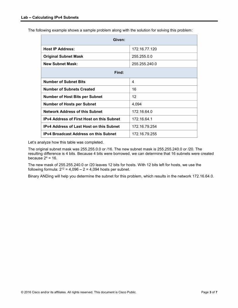
The following example shows a sample problem along with the solution for solving this problem:
Given:
Host IP Address: 172.16.77.120
Original Subnet Mask 255.255.0.0
New Subnet Mask: 255.255.240.0
Find:
Number of Subnet Bits 4
Number of Subnets Created 16
Number of Host Bits per Subnet 12
Number of Hosts per Subnet 4,094
Network Address of this Subnet 172.16.64.0
IPv4 Address of First Host on this Subnet 172.16.64.1
IPv4 Address of Last Host on this Subnet 172.16.79.254
IPv4 Broadcast Address on this Subnet 172.16.79.255
analyze how this table was completed.
The original subnet mask was 255.255.0.0 or /16. The new subnet mask is 255.255.240.0 or /20. The resulting difference is 4 bits. Because 4 bits were borrowed, we can determine that 16 subnets were created because 24 = 16.
The new mask of 255.255.240.0 or /20 leaves 12 bits for hosts. With 12 bits left for hosts, we use the following formula: 212 = 4,096 2 = 4,094 hosts per subnet.
Binary ANDing will help you determine the subnet for this problem, which results in the network 172.16.64.0.

Lab Calculating IPv4 Subnets
© 2016 Cisco and/or its affiliates. All rights reserved. This document is Cisco Public. Page 4 of 7
Finally, you need to determine the first host, last host, and broadcast address for each subnet. One method to determine the host range is to use binary math for the host portion of the address. In our example, the last 12 bits of the address is the host portion. The first host would have all significant bits set to zero and the least significant bit set to 1. The last host would have all significant bits set to 1 and the least significant bit set to 0. In this example, the host portion of the address resides in the 3rd and 4th octets.
Description 1st Octet 2nd Octet 3rd Octet 4th Octet Description
Network/Host nnnnnnnn nnnnnnnn nnnnhhhh hhhhhhhh Subnet Mask
Binary 10101100 00010000 01000000 00000001 First Host
Decimal 172 16 64 1 First Host
Binary 10101100 00010000 01001111 11111110 Last Host
Decimal 172 16 79 254 Last Host
Binary 10101100 00010000 01001111 11111111 Broadcast
Decimal 172 16 79 255 Broadcast
Step 1: Fill out the tables below with appropriate answers given the IPv4 address, original subnet mask, and new subnet mask.
a. Problem 1:
Given:
Host IP Address: 192.168.200.139
Original Subnet Mask 255.255.255.0
New Subnet Mask: 255.255.255.224
Find:
Number of Subnet Bits
Number of Subnets Created
Number of Host Bits per Subnet
Number of Hosts per Subnet
Network Address of this Subnet
IPv4 Address of First Host on this Subnet
IPv4 Address of Last Host on this Subnet
IPv4 Broadcast Address on this Subnet

Lab Calculating IPv4 Subnets
© 2016 Cisco and/or its affiliates. All rights reserved. This document is Cisco Public. Page 5 of 7
b. Problem 2:
Given:
Host IP Address: 10.101.99.228
Original Subnet Mask 255.0.0.0
New Subnet Mask: 255.255.128.0
Find:
Number of Subnet Bits
Number of Subnets Created
Number of Host Bits per Subnet
Number of Hosts per Subnet
Network Address of this Subnet
IPv4 Address of First Host on this Subnet
IPv4 Address of Last Host on this Subnet
IPv4 Broadcast Address on this Subnet
c. Problem 3:
Given:
Host IP Address: 172.22.32.12
Original Subnet Mask 255.255.0.0
New Subnet Mask: 255.255.224.0
Find:
Number of Subnet Bits
Number of Subnets Created
Number of Host Bits per Subnet
Number of Hosts per Subnet
Network Address of this Subnet
IPv4 Address of First Host on this Subnet
IPv4 Address of Last Host on this Subnet
IPv4 Broadcast Address on this Subnet
Lab Calculating IPv4 Subnets
© 2016 Cisco and/or its affiliates. All rights reserved. This document is Cisco Public. Page 6 of 7
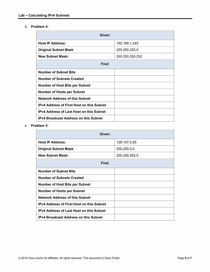
d. Problem 4:
Given:
Host IP Address: 192.168.1.245
Original Subnet Mask 255.255.255.0
New Subnet Mask: 255.255.255.252
Find:
Number of Subnet Bits
Number of Subnets Created
Number of Host Bits per Subnet
Number of Hosts per Subnet
Network Address of this Subnet
IPv4 Address of First Host on this Subnet
IPv4 Address of Last Host on this Subnet
IPv4 Broadcast Address on this Subnet
e. Problem 5:
Given:
Host IP Address: 128.107.0.55
Original Subnet Mask 255.255.0.0
New Subnet Mask: 255.255.255.0
Find:
Number of Subnet Bits
Number of Subnets Created
Number of Host Bits per Subnet
Number of Hosts per Subnet
Network Address of this Subnet
IPv4 Address of First Host on this Subnet
IPv4 Address of Last Host on this Subnet
IPv4 Broadcast Address on this Subnet

Lab Calculating IPv4 Subnets
© 2016 Cisco and/or its affiliates. All rights reserved. This document is Cisco Public. Page 7 of 7
f. Problem 6:
Given:
Host IP Address: 192.135.250.180
Original Subnet Mask 255.255.255.0
New Subnet Mask: 255.255.255.248
Find:
Number of Subnet Bits
Number of Subnets Created
Number of Host Bits per Subnet
Number of Hosts per Subnet
Network Address of this Subnet
IPv4 Address of First Host on this Subnet
IPv4 Address of Last Host on this Subnet
IPv4 Broadcast Address on this Subnet
Reflection
Why is the subnet mask so important when analyzing an IPv4 address?
_______________________________________________________________________________________
_______________________________________________________________________________________
_______________________________________________________________________________________

© 2016 Cisco and/or its affiliates. All rights reserved. This document is Cisco Public. Page 1 of 4
Lab - Designing and Implementing a Subnetted IPv4 Addressing Scheme
Topology
Addressing Table
Device Interface IP Address Subnet Mask Default Gateway
R1 G0/0 N/A
G0/1 N/A
Lo0 N/A
Lo1 N/A
S1 VLAN 1 N/A N/A N/A
PC-A NIC
PC-B NIC
Objectives
Part 1: Design a Network Subnetting Scheme
Part 2: Configure the Devices
Part 3: Test and Troubleshoot the Network
Background / Scenario
In this lab, starting from a single network address and network mask, you will subnet the network into multiple subnets. The subnet scheme should be based on the number of host computers required in each subnet, as well as other network considerations, like future network host expansion.
After you have created a subnetting scheme and completed the network diagram by filling in the host and interface IP addresses, you will configure the host PCs and router interfaces, including loopback interfaces. The loopback interfaces are created to simulate additional LANs attached to router R1.
After the network devices and host PCs have been configured, you will use the ping command to test for network connectivity.
This lab provides minimal assistance with the actual commands necessary to configure the router. However, the required commands are provided in Appendix A. Test your knowledge by trying to configure the devices without referring to the appendix.

Lab - Designing and Implementing a Subnetted IPv4 Addressing Scheme
© 2016 Cisco and/or its affiliates. All rights reserved. This document is Cisco Public. Page 2 of 4
Note: The routers used with CCNA hands-on labs are Cisco 1941 Integrated Services Routers (ISRs) with Cisco IOS Release 15.2(4)M3 (universalk9 image). The switches used are Cisco Catalyst 2960s with Cisco IOS Release 15.0(2) (lanbasek9 image). Other routers, switches and Cisco IOS versions can be used. Depending on the model and Cisco IOS version, the commands available and output produced might vary from what is shown in the labs. Refer to the Router Interface Summary Table at this end of the lab for the correct interface identifiers.
Note: Make sure that the routers and switches have been erased and have no startup configurations. If you are unsure, contact your instructor.
Required Resources
1 Router (Cisco 1941 with Cisco IOS Release 15.2(4)M3 universal image or comparable)
1 Switch (Cisco 2960 with Cisco IOS Release 15.0(2) lanbasek9 image or comparable)
2 PCs (Windows 7 or 8 with terminal emulation program, such as Tera Term)
Console cables to configure the Cisco IOS devices via the console ports
Ethernet cables as shown in the topology
Note: The Gigabit Ethernet interfaces on Cisco 1941 routers are autosensing. An Ethernet straight-through cable may be used between the router and PC-B. If using another Cisco router model, it may be necessary to use an Ethernet crossover cable.
Design a Network Subnetting Scheme
Step 1: Create a subnetting scheme that meets the required number of subnets and required number of host addresses.
In this scenario, you are a network administrator for a small subdivision within a larger company. You must create multiple subnets out of the 192.168.0.0/24 network address space to meet the following requirements:
The first subnet is the employee network. You need a minimum of 25 host IP addresses.
The second subnet is the administration network. You need a minimum of 10 IP addresses.
The third and fourth subnets are reserved as virtual networks on virtual router interfaces, loopback 0 and loopback 1. These virtual router interfaces simulate LANs attached to R1.
You also need two additional unused subnets for future network expansion.
Note: Variable length subnet masks will not be used. All of the device subnet masks will be the same length.
Answer the following questions to help create a subnetting scheme that meets the stated network requirements:
1) How many host addresses are needed in the largest required subnet? _____________________
2) What is the minimum number of subnets required? _________________________________
3) The network that you are tasked to subnet is 192.168.0.0/24. What is the /24 subnet mask in binary?
________________________________________________________________________________
4) The subnet mask is made up of two portions, the network portion, and the host portion. This is represented in the binary by the ones and the zeros in the subnet mask.
In the network mask, what do the ones represent? ________________________________________
In the network mask, what do the zeros represent? _______________________________________

Lab - Designing and Implementing a Subnetted IPv4 Addressing Scheme
© 2016 Cisco and/or its affiliates. All rights reserved. This document is Cisco Public. Page 3 of 4
5) To subnet a network, bits from the host portion of the original network mask are changed into subnet bits. The number of subnet bits defines the number of subnets. Given each of the possible subnet masks depicted in the following binary format, how many subnets and how many hosts are created in each example?
Hint: Remember that the number of host bits (to the power of 2) defines the number of hosts per subnet (minus 2), and the number of subnet bits (to the power of two) defines the number of subnets. The subnet bits (depicted in bold type face) are the bits that have been borrowed beyond the original network mask of /24. The /24 is the slash prefix notation and corresponds to a dotted decimal mask of 255.255.255.0.
(/25) 11111111.11111111.11111111.10000000
Dotted decimal subnet mask equivalent: ________________________________
Number of subnets? ________________, Number of hosts? ________________
(/26) 11111111.11111111.11111111.11000000
Dotted decimal subnet mask equivalent: ________________________________
Number of subnets? ________________, Number of hosts? ________________
(/27) 11111111.11111111.11111111.11100000
Dotted decimal subnet mask equivalent: ________________________________
Number of subnets? ________________ Number of hosts? ________________
(/28) 11111111.11111111.11111111.11110000
Dotted decimal subnet mask equivalent: ________________________________
Number of subnets? ________________ Number of hosts? _________________
(/29) 11111111.11111111.11111111.11111000
Dotted decimal subnet mask equivalent: ________________________________
Number of subnets? ________________ Number of hosts? _________________
(/30) 11111111.11111111.11111111.11111100
Dotted decimal subnet mask equivalent: ________________________________
Number of subnets? ________________ Number of hosts? _________________
6) Considering your answers, which subnet masks meet the required number of minimum host addresses?
________________________________________________________________________________
7) Considering your answers, which subnet masks meets the minimum number of subnets required?
________________________________________________________________________________
8) Considering your answers, which subnet mask meets both the required minimum number of hosts and the minimum number of subnets required?
________________________________________________________________________________

Lab - Designing and Implementing a Subnetted IPv4 Addressing Scheme
© 2016 Cisco and/or its affiliates. All rights reserved. This document is Cisco Public. Page 4 of 4
9) When you have determined which subnet mask meets all of the stated network requirements, you will derive each of the subnets starting from the original network address. List the subnets from first to last below. Remember that the first subnet is 192.168.0.0 with the newly acquired subnet mask.
Subnet Address / Prefix Subnet Mask (dotted decimal)
___________________ / ____ __________________________
___________________ / ____ __________________________
___________________ / ____ __________________________
___________________ / ____ __________________________
___________________ / ____ __________________________
___________________ / ____ __________________________
___________________ / ____ __________________________
___________________ / ____ __________________________
___________________ / ____ __________________________
___________________ / ____ __________________________
Step 2: Complete the diagram showing where the host IP addresses will be applied.
On the following lines provided, fill in the IP addresses and subnets masks in slash prefix notation. On the router, use the first usable address in each subnet for each of the interfaces, Gigabit Ethernet 0/0, Gigabit Ethernet 0/1, loopback 0, and loopback 1. Fill in an IP address for both PC-A and PC-B. Also enter this information into the Addressing Table on Page 1.
Reflection
1. Subnetting one larger network into multiple smaller subnetworks allows for greater flexibility and security in network design. However, what do you think some of the drawbacks are when the subnets are limited to being the same size?
_______________________________________________________________________________________
_______________________________________________________________________________________
2. Why do you think the gateway/router IP address is usually the first usable IP address in the network?
_______________________________________________________________________________________

© 2016 Cisco and/or its affiliates. All rights reserved. This document is Cisco Public. Page 1 of 5
Lab Designing and Implementing a VLSM Addressing Scheme
Topology
Objectives
Part 1: Examine Network Requirements
Part 2: Design the VLSM Address Scheme
Part 3: Cable and Configure the IPv4 Network
Background / Scenario
Variable Length Subnet Mask (VLSM) was designed to avoid wasting IP addresses. With VLSM, a network is subnetted and then re-subnetted. This process can be repeated multiple times to create subnets of various sizes based on the number of hosts required in each subnet. Effective use of VLSM requires address planning.
In this lab, use the 172.16.128.0/17 network address to develop an address scheme for the network displayed in the topology diagram. VLSM is used to meet the IPv4 addressing requirements. After you have designed the VLSM address scheme, you will configure the interfaces on the routers with the appropriate IP address information.
Note: The routers used with CCNA hands-on labs are Cisco 1941 Integrated Services Routers (ISRs) with Cisco IOS Release 15.2(4)M3 (universalk9 image). Other routers and Cisco IOS versions can be used. Depending on the model and Cisco IOS version, the commands available and output produced might vary from what is shown in the labs. Refer to the Router Interface Summary Table at the end of this lab for the correct interface identifiers.
Note: Make sure that the routers have been erased and have no startup configurations. If you are unsure, contact your instructor.
Required Resources
3 routers (Cisco 1941 with Cisco IOS software, Release 15.2(4)M3 universal image or comparable)
1 PC (with terminal emulation program, such as Tera Term, to configure routers)
Console cable to configure the Cisco IOS devices via the console ports
Ethernet (optional) and serial cables, as shown in the topology

Lab Designing and Implementing a VLSM Addressing Scheme
© 2016 Cisco and/or its affiliates. All rights reserved. This document is Cisco Public. Page 2 of 5
Windows Calculator (optional)
Part 1: Examine Network Requirements
In Part 1, you will examine the network requirements to develop a VLSM address scheme for the network displayed in the topology diagram using the 172.16.128.0/17 network address.
Note: You can use the Windows Calculator application and the www.ipcalc.org IP subnet calculator to help with your calculations.
Step 1: Determine how many host addresses and subnets are available.
How many host addresses are available in a /17 network? ________
What is the total number of host addresses needed in the topology diagram? ________
How many subnets are needed in the network topology? ______
Step 2: Determine the largest subnet.
What is the subnet description (e.g. BR1 G0/1 LAN or BR1-HQ WAN link)? ___________________
How many IP addresses are required in the largest subnet? __________
What subnet mask can support that many host addresses?
_____________________
How many total host addresses can that subnet mask support? _________
Can you subnet the 172.16.128.0/17 network address to support this subnet? _____
What are the two network addresses that would result from this subnetting?
_____________________
_____________________
Use the first network address for this subnet.
Step 3: Determine the second largest subnet.
What is the subnet description? _____________________________
How many IP addresses are required for the second largest subnet? ______
What subnet mask can support that many host addresses?
___________________
How many total host addresses can that subnet mask support? __________
Can you subnet the remaining subnet again and still support this subnet? ______
What are the two network addresses that would result from this subnetting?
_____________________
_____________________
Use the first network address for this subnet.
Step 4: Determine the next largest subnet.
What is the subnet description? _____________________________
How many IP addresses are required for the next largest subnet? ______

Lab Designing and Implementing a VLSM Addressing Scheme
© 2016 Cisco and/or its affiliates. All rights reserved. This document is Cisco Public. Page 3 of 5
What subnet mask can support that many host addresses?
___________________
How many total host addresses can that subnet mask support? __________
Can you subnet the remaining subnet again and still support this subnet? ______
What are the two network addresses that would result from this subnetting?
_____________________
_____________________
Use the first network address for this subnet.
Step 5: Determine the next largest subnet.
What is the subnet description? _____________________________
How many IP addresses are required for the next largest subnet? ______
What subnet mask can support that many host addresses?
___________________
How many total host addresses can that subnet mask support? __________
Can you subnet the remaining subnet again and still support this subnet? ______
What are the two network addresses that would result from this subnetting?
_____________________
_____________________
Use the first network address for this subnet.
Step 6: Determine the next largest subnet.
What is the subnet description? _____________________________
How many IP addresses are required for the next largest subnet? ______
What subnet mask can support that many host addresses?
___________________
How many total host addresses can that subnet mask support? __________
Can you subnet the remaining subnet again and still support this subnet? ______
What are the two network addresses that would result from this subnetting?
_____________________
_____________________
Use the first network address for this subnet.
Step 7: Determine the next largest subnet.
What is the subnet description? _____________________________
How many IP addresses are required for the next largest subnet? ______
What subnet mask can support that many host addresses?
___________________
Lab Designing and Implementing a VLSM Addressing Scheme
© 2016 Cisco and/or its affiliates. All rights reserved. This document is Cisco Public. Page 4 of 5
How many total host addresses can that subnet mask support? __________
Can you subnet the remaining subnet again and still support this subnet? ______
What are the two network addresses that would result from this subnetting?
_____________________
_____________________
Use the first network address for this subnet.
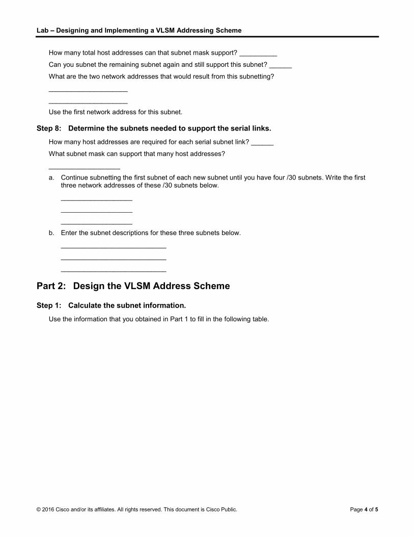
Step 8: Determine the subnets needed to support the serial links.
How many host addresses are required for each serial subnet link? ______
What subnet mask can support that many host addresses?
___________________
a. Continue subnetting the first subnet of each new subnet until you have four /30 subnets. Write the first three network addresses of these /30 subnets below.
___________________
___________________
___________________
b. Enter the subnet descriptions for these three subnets below.
____________________________
____________________________
____________________________
Part 2: Design the VLSM Address Scheme
Step 1: Calculate the subnet information.
Use the information that you obtained in Part 1 to fill in the following table.

Lab Designing and Implementing a VLSM Addressing Scheme
© 2016 Cisco and/or its affiliates. All rights reserved. This document is Cisco Public. Page 5 of 5
Subnet Description Number of
Hosts Needed Network Address
/CIDR First Host Address
Broadcast Address
HQ G0/0 16,000
HQ G0/1 8,000
BR1 G0/1 4,000
BR1 G0/0 2,000
BR2 G0/1 1,000
BR2 G0/0 500
HQ S0/0/0 BR1 S0/0/0 2
HQ S0/0/1 BR2 S0/0/1 2
BR1 S0/0/1 BR2 S0/0/0 2
Step 2: Complete the device interface address table.
Assign the first host address in the subnet to the Ethernet interfaces. HQ should be given the first host address on the Serial links to BR1 and BR2. BR1 should be given the first host address for the serial link to BR2.
Device Interface IP Address Subnet Mask Device Interface
HQ
G0/0 16,000 Host LAN
G0/1 8,000 Host LAN
S0/0/0 BR1 S0/0/0
S0/0/1 BR2 S0/0/1
BR1
G0/0 2,000 Host LAN
G0/1 4,000 Host LAN
S0/0/0 HQ S0/0/0
S0/0/1 BR2 S0/0/0
BR2
G0/0 500 Host LAN
G0/1 1,000 Host LAN
S0/0/0 BR1 S0/0/1
S0/0/1 HQ S0/0/1
Reflection
Can you think of a shortcut for calculating the network addresses of consecutive /30 subnets?
_______________________________________________________________________________________
_______________________________________________________________________________________
_______________________________________________________________________________________

© 2016 Cisco and/or its affiliates. All rights reserved. This document is Cisco Public. Page 1 of 7
Lab - Using Wireshark to Observe the TCP 3-Way Handshake
Topology
Objectives
Part 1: Prepare Wireshark to Capture Packets
Part 2: Capture, Locate, and Examine Packets
Background / Scenario
In this lab, you will use Wireshark to capture and examine packets generated between the PC browser using the HyperText Transfer Protocol (HTTP) and a web server, such as www.google.com. When an application, such as HTTP or File Transfer Protocol (FTP) first starts on a host, TCP uses the three-way handshake to establish a reliable TCP session between the two hosts. For example, when a PC uses a web browser to surf the Internet, a three-way handshake is initiated, and a session is established between the PC host and web server. A PC can have multiple, simultaneous, active TCP sessions with various web sites.
Note: This lab cannot be completed using Netlab. This lab assumes that you have Internet access.
Required Resources
1 PC (Windows 7 or 8 with a command prompt access, Internet access, and Wireshark installed)
Part 1: Prepare Wireshark to Capture Packets
In Part 1, you will start the Wireshark program and select the appropriate interface to begin capturing packets.
Step 1: Retrieve the PC interface addresses.
For this lab, address and its network interface card (NIC) physical address, also called the MAC address.
a. Open a command prompt window, type ipconfig /all, and press Enter.
b. Write down the IP and MAC addresses associated with the selected Ethernet adapter. That is the source address to look for when examining captured packets.
The PC host IP address: ____________________________________________________________
The PC host MAC address: __________________________________________________________

Lab - Using Wireshark to Observe the TCP 3-Way Handshake
© 2016 Cisco and/or its affiliates. All rights reserved. This document is Cisco Public. Page 2 of 7
Step 2: Start Wireshark and select the appropriate interface.
a. Click the Windows Start button. In the pop-up menu, double-click Wireshark.
b. After Wireshark starts, click Interface List.
c. In the Wireshark: Capture Interfaces window, click the check the box next to the interface that is connected to your LAN.
Note: If multiple interfaces are listed and you are unsure which interface to select, click Details. Click the 802.3 (Ethernet) tab, and verify that the MAC address matches what you wrote down in Step 1b. Close the Interface Details window after verification.

Lab - Using Wireshark to Observe the TCP 3-Way Handshake
© 2016 Cisco and/or its affiliates. All rights reserved. This document is Cisco Public. Page 3 of 7
Part 2: Capture, Locate, and Examine Packets
Step 1: Capture the data.
a. Click the Start button to start the data capture.
b. Navigate to www.google.com. Minimize the browser and return to Wireshark. Stop the data capture.
Note: Your instructor may provide you with a different website. If so, enter the website name or address here:
____________________________________________________________________________________
The capture window is now active. Locate the Source, Destination, and Protocol columns.
Step 2: Locate appropriate packets for the web session.
If the computer was recently started and there has been no activity in accessing the Internet, you can see the entire process in the captured output, including the Address Resolution Protocol (ARP), Domain Name System (DNS), and the TCP three-way handshake. If the PC already had an ARP entry for the default gateway; therefore, it started with the DNS query to resolve www.google.com.
a. Frame 11 shows the DNS query from the PC to the DNS server, which is attempting to resolve the domain name www.google.com to the IP address of the web server. The PC must have the IP address before it can send the first packet to the web server.
What is the IP address of the DNS server that the computer queried? ____________________
b. Frame 13 is the response from the DNS server. It contains the IP address of www.google.com.
c. Find the appropriate packet for the start of your three-way handshake. In the example, frame 14 is the start of the TCP three-way handshake.
What is the IP address of the Google web server? __________________________________

Lab - Using Wireshark to Observe the TCP 3-Way Handshake
© 2016 Cisco and/or its affiliates. All rights reserved. This document is Cisco Public. Page 4 of 7
d. If you have many packets that are unrelated to the TCP connection, it may be necessary to use the Wireshark filter tool. Type tcp in the filter entry area within Wireshark and press Enter.
Step 3: Examine the information within packets including IP addresses, TCP port numbers, and TCP control flags.
a. In our example, frame 14 is the start of the three-way handshake between the PC and the Google web server. In the packet list pane (top section of the main window), select the frame. This highlights the line and displays the decoded information from that packet in the two lower panes. Examine the TCP information in the packet details pane (middle section of the main window).
b. Click the + icon to the left of the Transmission Control Protocol in the packet details pane to expand the view of the TCP information.

Lab - Using Wireshark to Observe the TCP 3-Way Handshake
© 2016 Cisco and/or its affiliates. All rights reserved. This document is Cisco Public. Page 5 of 7
c. Click the + icon to the left of the Flags. Look at the source and destination ports and the flags that are set.
Note: You may have to adjust the top and middle windows sizes within Wireshark to display the necessary information.
What is the TCP source port number? __________________________
How would you classify the source port? ________________________
What is the TCP destination port number? _______________________
How would you classify the destination port? _____________________
Which flag (or flags) is set? ________________________
What is the relative sequence number set to? ____________________

Lab - Using Wireshark to Observe the TCP 3-Way Handshake
© 2016 Cisco and/or its affiliates. All rights reserved. This document is Cisco Public. Page 6 of 7
d. To select the next frame in the three-way handshake, select Go on the Wireshark menu and select Next Packet In Conversation. In this example, this is frame 15. This is the Google web server reply to the initial request to start a session.
What are the values of the source and destination ports? ______________________________________
Which flags are set? ___________________________________________________________________
What are the relative sequence and acknowledgement numbers set to?
____________________________________________________________________________________

Lab - Using Wireshark to Observe the TCP 3-Way Handshake
© 2016 Cisco and/or its affiliates. All rights reserved. This document is Cisco Public. Page 7 of 7
e. Finally, examine the third packet of the three-way handshake in the example. Click frame 16 in the top window to display the following information in this example:
Examine the third and final packet of the handshake.
Which flag (or flags) is set? _____________________________________________________________
The relative sequence and acknowledgement numbers are set to 1 as a starting point. The TCP connection is established and communication between the source computer and the web server can begin.
f. Close the Wireshark program.
Reflection
1. There are hundreds of filters available in Wireshark. A large network could have numerous filters and many different types of traffic. List three filters that might be useful to a network administrator?
_______________________________________________________________________________________
2. What other ways could Wireshark be used in a production network?
_______________________________________________________________________________________

© 2016 Cisco and/or its affiliates. All rights reserved. This document is Cisco Public. Page 1 of 1
Lab - Using Wireshark to Examine TCP and UDP Captures
Topology Part 1 (FTP)
Part 1 will highlight a TCP capture of an FTP session. This topology consists of a PC with Internet access.
Topology Part 2 (TFTP)
Part 2 will highlight a UDP capture of a TFTP session. The PC must have both an Ethernet connection and a console connection to Switch S1.
Addressing Table (Part 2)
Device Interface IP Address Subnet Mask Default Gateway
S1 VLAN 1 192.168.1.1 255.255.255.0 N/A
PC-A NIC 192.168.1.3 255.255.255.0 192.168.1.1
Objectives
Part 1: Identify TCP Header Fields and Operation Using a Wireshark FTP Session Capture
Part 2: Identify UDP Header Fields and Operation Using a Wireshark TFTP Session Capture
Background / Scenario
Two protocols in the TCP/IP transport layer are TCP (defined in RFC 761) and UDP (defined in RFC 768). Both protocols support upper-layer protocol communication. For example, TCP is used to provide transport layer support for the HyperText Transfer Protocol (HTTP) and FTP protocols, among others. UDP provides transport layer support for the Domain Name System (DNS) and TFTP, among others.
Note: Understanding the parts of the TCP and UDP headers and operation are a critical skill for network engineers.
Lab - Using Wireshark to Examine TCP and UDP Captures
© 2016 Cisco and/or its affiliates. All rights reserved. This document is Cisco Public. Page 2 of 2
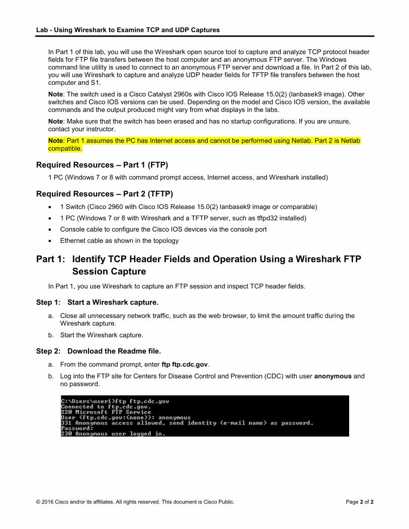
In Part 1 of this lab, you will use the Wireshark open source tool to capture and analyze TCP protocol header fields for FTP file transfers between the host computer and an anonymous FTP server. The Windows command line utility is used to connect to an anonymous FTP server and download a file. In Part 2 of this lab, you will use Wireshark to capture and analyze UDP header fields for TFTP file transfers between the host computer and S1.
Note: The switch used is a Cisco Catalyst 2960s with Cisco IOS Release 15.0(2) (lanbasek9 image). Other switches and Cisco IOS versions can be used. Depending on the model and Cisco IOS version, the available commands and the output produced might vary from what displays in the labs.
Note: Make sure that the switch has been erased and has no startup configurations. If you are unsure, contact your instructor.
Note: Part 1 assumes the PC has Internet access and cannot be performed using Netlab. Part 2 is Netlab compatible.
Required Resources Part 1 (FTP)
1 PC (Windows 7 or 8 with command prompt access, Internet access, and Wireshark installed)
Required Resources Part 2 (TFTP)
1 Switch (Cisco 2960 with Cisco IOS Release 15.0(2) lanbasek9 image or comparable)
1 PC (Windows 7 or 8 with Wireshark and a TFTP server, such as tftpd32 installed)
Console cable to configure the Cisco IOS devices via the console port
Ethernet cable as shown in the topology
Part 1: Identify TCP Header Fields and Operation Using a Wireshark FTP Session Capture
In Part 1, you use Wireshark to capture an FTP session and inspect TCP header fields.
Step 1: Start a Wireshark capture.
a. Close all unnecessary network traffic, such as the web browser, to limit the amount traffic during the Wireshark capture.
b. Start the Wireshark capture.
Step 2: Download the Readme file.
a. From the command prompt, enter ftp ftp.cdc.gov.
b. Log into the FTP site for Centers for Disease Control and Prevention (CDC) with user anonymous and no password.

Lab - Using Wireshark to Examine TCP and UDP Captures
© 2016 Cisco and/or its affiliates. All rights reserved. This document is Cisco Public. Page 3 of 3
c. Locate and download the Readme file by entering the ls command to list the files.
d. Enter the command get Readme to download the file. When the download is complete, enter the command quit to exit.
Step 3: Stop the Wireshark capture.
Step 4: View the Wireshark main window.
Wireshark captured many packets during the FTP session to ftp.cdc.gov. To limit the amount of data for analysis, type tcp and ip.addr == 198.246.117.106 in the Filter: entry area and click Apply. The IP address, 198.246.117.106, is the address for ftp.cdc.gov at this time.

Lab - Using Wireshark to Examine TCP and UDP Captures
© 2016 Cisco and/or its affiliates. All rights reserved. This document is Cisco Public. Page 4 of 4
Step 5: Analyze the TCP fields.
After the TCP filter has been applied, the first three frames in the packet list pane (top section) display the transport layer protocol TCP creating a reliable session. The sequence of [SYN], [SYN, ACK], and [ACK] illustrates the three-way handshake.
TCP is routinely used during a session to control datagram delivery, verify datagram arrival, and manage window size. For each data exchange between the FTP client and FTP server, a new TCP session is started. At the conclusion of the data transfer, the TCP session is closed. When the FTP session is finished, TCP performs an orderly shutdown and termination.
In Wireshark, detailed TCP information is available in the packet details pane (middle section). Highlight the first TCP datagram from the host computer, and expand the TCP datagram. The expanded TCP datagram appears similar to the packet detail pane shown below.
The image above is a TCP datagram diagram. An explanation of each field is provided for reference:

Lab - Using Wireshark to Examine TCP and UDP Captures
© 2016 Cisco and/or its affiliates. All rights reserved. This document is Cisco Public. Page 5 of 5
The TCP source port number belongs to the TCP session host that opened a connection. The value is normally a random value above 1,023.
The TCP destination port number is used to identify the upper layer protocol or application on the remote site. The values in the range 0 1, -popular services and applications (as described in RFC 1700), such as Telnet, FTP, and HTTP. The combination of the source IP address, source port, destination IP address, and destination port uniquely identifies the session to the sender and receiver.
Note: In the Wireshark capture below, the destination port is 21, which is FTP. FTP servers listen on port 21 for FTP client connections.
The Sequence number specifies the number of the last octet in a segment.
The Acknowledgment number specifies the next octet expected by the receiver.
The Code bits have a special meaning in session management and in the treatment of segments. Among interesting values are:
- ACK Acknowledgement of a segment receipt.
- SYN Synchronize, only set when a new TCP session is negotiated during the TCP three-way handshake.
- FIN Finish, the request to close the TCP session.
The Window size is the value of the sliding window. It determines how many octets can be sent before waiting for an acknowledgement.
The Urgent pointer is only used with an Urgent (URG) flag when the sender needs to send urgent data to the receiver.
The Options has only one option currently, and it is defined as the maximum TCP segment size (optional value).
Using the Wireshark capture of the first TCP session startup (SYN bit set to 1), fill in information about the TCP header.
From the PC to CDC server (only the SYN bit is set to 1):
Source IP address
Destination IP address
Source port number
Destination port number
Sequence number
Acknowledgement number
Header length
Window size

Lab - Using Wireshark to Examine TCP and UDP Captures
© 2016 Cisco and/or its affiliates. All rights reserved. This document is Cisco Public. Page 6 of 6
In the second Wireshark filtered capture, the CDC FTP server acknowledges the request from the PC. Note the values of the SYN and ACK bits.
Fill in the following information regarding the SYN-ACK message.
Source IP address
Destination IP address
Source port number
Destination port number
Sequence number
Acknowledgement number
Header length
Window size

Lab - Using Wireshark to Examine TCP and UDP Captures
© 2016 Cisco and/or its affiliates. All rights reserved. This document is Cisco Public. Page 7 of 7
In the final stage of the negotiation to establish communications, the PC sends an acknowledgement message to the server. Notice only the ACK bit is set to 1, and the Sequence number has been incremented to 1.
Fill in the following information regarding the ACK message.
Source IP address
Destination IP address
Source port number
Destination port number
Sequence number
Acknowledgement number
Header length
Window size
How many other TCP datagrams contained a SYN bit?
_______________________________________________________________________________________

Lab - Using Wireshark to Examine TCP and UDP Captures
© 2016 Cisco and/or its affiliates. All rights reserved. This document is Cisco Public. Page 8 of 8
After a TCP session is established, FTP traffic can occur between the PC and FTP server. The FTP client and server communicate with each other, unaware that TCP has control and management over the session. When the FTP server sends a Response: 220 to the FTP client, the TCP session on the FTP client sends an acknowledgment to the TCP session on the server. This sequence is visible in the Wireshark capture below.
server acknowledges the FTP termination with a Response: 221 Goodbye. At this time, the FTP server TCP session sends a TCP datagram to the FTP client, announcing the termination of the TCP session. The FTP client TCP session acknowledges receipt of the termination datagram, then sends its own TCP session termination. When the originator of the TCP termination (the FTP server) receives a duplicate termination, an ACK datagram is sent to acknowledge the termination and the TCP session is closed. This sequence is visible in the diagram and capture below.
Lab - Using Wireshark to Examine TCP and UDP Captures
© 2016 Cisco and/or its affiliates. All rights reserved. This document is Cisco Public. Page 9 of 9
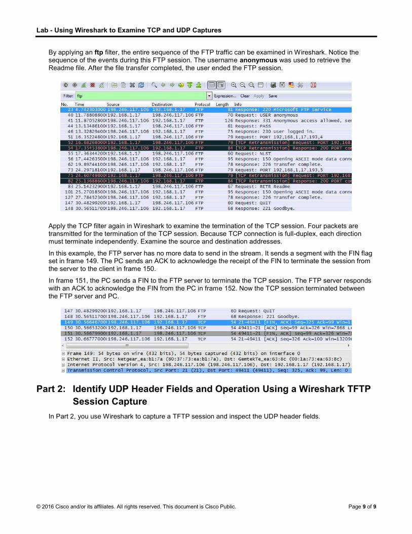
By applying an ftp filter, the entire sequence of the FTP traffic can be examined in Wireshark. Notice the sequence of the events during this FTP session. The username anonymous was used to retrieve the Readme file. After the file transfer completed, the user ended the FTP session.
Apply the TCP filter again in Wireshark to examine the termination of the TCP session. Four packets are transmitted for the termination of the TCP session. Because TCP connection is full-duplex, each direction must terminate independently. Examine the source and destination addresses.
In this example, the FTP server has no more data to send in the stream. It sends a segment with the FIN flag set in frame 149. The PC sends an ACK to acknowledge the receipt of the FIN to terminate the session from the server to the client in frame 150.
In frame 151, the PC sends a FIN to the FTP server to terminate the TCP session. The FTP server responds with an ACK to acknowledge the FIN from the PC in frame 152. Now the TCP session terminated between the FTP server and PC.
Part 2: Identify UDP Header Fields and Operation Using a Wireshark TFTP Session Capture
In Part 2, you use Wireshark to capture a TFTP session and inspect the UDP header fields.

Lab - Using Wireshark to Examine TCP and UDP Captures
© 2016 Cisco and/or its affiliates. All rights reserved. This document is Cisco Public. Page 10 of 10
Step 1: Set up this physical topology and prepare for TFTP capture.
a. Establish a console and Ethernet connection between PC-A and S1.
b. Manually configure the IP address on the PC to 192.168.1.3. It is not required to set the default gateway.
c. Configure the switch. Assign an IP address of 192.168.1.1 to VLAN 1. Verify connectivity with the PC by pinging 192.168.1.3. Troubleshoot as necessary.
Switch> enable
Switch# conf t
Enter configuration commands, one per line. End with CNTL/Z.
Switch(config)# host S1
S1(config)# interface vlan 1
S1(config-if)# ip address 192.168.1.1 255.255.255.0
S1(config-if)# no shut
*Mar 1 00:37:50.166: %LINK-3-UPDOWN: Interface Vlan1, changed state to up
*Mar 1 00:37:50.175: %LINEPROTO-5-UPDOWN: Line protocol on Interface Vlan1, changed state to up S1(config-if)# end
S1# ping 192.168.1.3
Type escape sequence to abort.
Sending 5, 100-byte ICMP Echos to 192.168.1.3, timeout is 2 seconds:
!!!!!
Success rate is 100 percent (5/5), round-trip min/avg/max = 1/203/1007 ms
d. Save the running configuration to NVRAM. S1# copy run start
Step 2: Prepare the TFTP server on the PC.
a. If it does not already exist, create a folder on the PC desktop called TFTP. The files from the switch will be copied to this location.
b. Start tftpd32 on the PC.
c. Click Browse and change the current directory to C:\Users\user1\Desktop\TFTP by replacing user1 with your username.

Lab - Using Wireshark to Examine TCP and UDP Captures
© 2016 Cisco and/or its affiliates. All rights reserved. This document is Cisco Public. Page 11 of 11
The TFTP server should look like this:
Notice that in Current Directory, it lists the user and the Server (PC-A) interface with the IP address of 192.168.1.3.
d. Test the ability to copy a file using TFTP from the switch to the PC. Troubleshoot as necessary.
S1# copy start tftp
Address or name of remote host []? 192.168.1.3
Destination filename [s1-confg]?
!!
1638 bytes copied in 0.026 secs (63000 bytes/sec)
If you see that the file has been copied then you are ready to go on to the next step. If the file has not been copied, troubleshoot as needed. If you get the %Error opening tftp (Permission denied) error, determine whether your firewall is blocking TFTP and whether you are copying the file to a location where your username has adequate permission, such as the desktop.
Step 3: Capture a TFTP session in Wireshark
a. Open Wireshark. From the Edit menu, choose Preferences and click the (+) sign to expand Protocols. Scroll down and select UDP. Click the Validate the UDP checksum if possible check box and click Apply. Then click OK.
b. Start a Wireshark capture.
c. Run the copy start tftp command on the switch.

Lab - Using Wireshark to Examine TCP and UDP Captures
© 2016 Cisco and/or its affiliates. All rights reserved. This document is Cisco Public. Page 12 of 12
d. Stop the Wireshark capture.
e. Set the filter to tftp. Your output should look similar to the output shown above. This TFTP transfer is used to analyze transport layer UDP operations.
Detailed UDP information is available in the Wireshark packet details pane. Highlight the first UDP datagram from the host computer and move the mouse pointer to the packet details pane. It may be necessary to adjust the packet details pane and expand the UDP record by clicking the protocol expand box. The expanded UDP datagram should look similar to the diagram below.
The figure below is a UDP datagram diagram. Header information is sparse, compared to the TCP datagram. Similar to TCP, each UDP datagram is identified by the UDP source port and UDP destination port.
Using the Wireshark capture of the first UDP datagram, fill in information about the UDP header. The checksum value is a hexadecimal (base 16) value, denoted by the preceding 0x code:
Source IP address
Destination IP address
Source port number
Destination port number
UDP message length
UDP checksum

Lab - Using Wireshark to Examine TCP and UDP Captures
© 2016 Cisco and/or its affiliates. All rights reserved. This document is Cisco Public. Page 13 of 13
How does UDP verify datagram integrity?
____________________________________________________________________________________
____________________________________________________________________________________
Examine the first frame returned from the tftpd server. Fill in the information about the UDP header:
Source IP address
Destination IP address
Source port number
Destination port number
UDP message length
UDP checksum
Notice that the return UDP datagram has a different UDP source port, but this source port is used for the remainder of the TFTP transfer. Because there is no reliable connection, only the original source port used to begin the TFTP session is used to maintain the TFTP transfer.
Also, notice that the UDP Checksum is incorrect. This is most likely caused by UDP checksum offload. You can learn more about why this happens
Reflection
This lab provided the opportunity to analyze TCP and UDP protocol operations from captured FTP and TFTP sessions. How does TCP manage communication differently than UDP?
_______________________________________________________________________________________
_______________________________________________________________________________________
Challenge
Because neither FTP or TFTP are secure protocols, all transferred data is sent in clear text. This includes any user IDs, passwords, or clear-text file contents. Analyzing the upper-layer FTP session will quickly identify the user ID, password, and configuration file passwords. Upper-layer TFTP data examination is more complicated, but the data field can be examined, and the configuration user ID and password information extracted.
Cleanup
Unless directed otherwise by your instructor:
1) Remove the files that were copied to your PC.
2) Erase the configurations on S1.
3) Remove the manual IP address from the PC and restore Internet connectivity.

© 2016 Cisco and/or its affiliates. All rights reserved. This document is Cisco Public. Page 1 of 5
Lab - Observing DNS Resolution
Objectives
Part 1: Observe the DNS Conversion of a URL to an IP Address
Part 2: Observe DNS Lookup Using the nslookup Command on a Web Site
Part 3: Observe DNS Lookup Using the nslookup Command on Mail Servers
Background / Scenario
The Domain Name System (DNS) is invoked when you type a Uniform Resource Locator (URL), such as http://www.cisco.com, into a web browser. The first part of the URL describes which protocol is used. Common protocols are Hypertext Transfer Protocol (HTTP), Hypertext Transfer Protocol over Secure Socket Layer (HTTPS), and File Transfer Protocol (FTP).
DNS uses the second part of the URL, which in this example is www.cisco.com. DNS translates the domain name (www.cisco.com) to an IP address to allow the source host to reach the destination host. In this lab, you will observe DNS in action and use the nslookup (name server lookup) command to obtain additional DNS information. Work with a partner to complete this lab.
Required Resources
1 PC (Windows 7 or 8 with Internet and command prompt access)
Part 1: Observe the DNS Conversion of a URL to an IP Address
a. Click the Windows Start button, type cmd into the search field, and press Enter. The command prompt window appears.
b. At the command prompt, ping the URL for the Internet Corporation for Assigned Names and Numbers (ICANN) at www.icann.org. ICANN coordinates the DNS, IP addresses, top-level domain name system management, and root server system management functions. The computer must translate www.icann.org into an IP address to know where to send the Internet Control Message Protocol (ICMP) packets.
The first line of the output displays www.icann.org converted to an IP address by DNS. You should be able to see the effect of DNS, even if your institution has a firewall that prevents pinging, or if the destination server has prevented you from pinging its web server.
Note: If the domain name is resolved to an IPv6 address, use the command ping -4 www.icann.org to translate into an IPv4 address if desired.
Record the IP address of www.icann.org. __________________________________

Lab - Observing DNS Resolution
© 2016 Cisco and/or its affiliates. All rights reserved. This document is Cisco Public. Page 2 of 5
c. Type the IP address from step b into a web browser, instead of the URL. Click Continue to this website (not recommended). to proceed.
d. Notice that the ICANN home web page is displayed.
Most humans find it easier to remember words, rather than numbers. If you tell someone to go to www.icann.org, they can probably remember that. If you told them to go to 192.0.32.7, they would have a difficult time remembering an IP address. Computers process in numbers. DNS is the process of translating words into numbers. There is a second translation that takes place. Humans think in Base 10 numbers. Computers process in Base 2 numbers. The Base 10 IP address 192.0.32.7 in Base 2 numbers is 11000000.00000000.00100000.00000111. What happens if you cut and paste these Base 2 numbers into a browser?
____________________________________________________________________________________
____________________________________________________________________________________

Lab - Observing DNS Resolution
© 2016 Cisco and/or its affiliates. All rights reserved. This document is Cisco Public. Page 3 of 5
e. Now type ping www.cisco.com.
Note: If the domain name is resolved to an IPv6 address, use the command ping -4 www.cisco.com to translate into an IPv4 address if desired.
f. When you ping www.cisco.com, do you get the same IP address as the example? Explain.
____________________________________________________________________________________
____________________________________________________________________________________
____________________________________________________________________________________
g. Type the IP address that you obtained when you pinged www.cisco.com into a browser. Does the web site display? Explain.
____________________________________________________________________________________
____________________________________________________________________________________
____________________________________________________________________________________
Part 2: Observe DNS Lookup Using the nslookup Command on a Web Site
a. At the command prompt, type the nslookup command.
What is the default DNS server used? _________________________________________
Notice how the command prompt changed to a greater than (>) symbol. This is the nslookup prompt. From this prompt, you can enter commands related to DNS.
At the prompt, type ? to see a list of all the available commands that you can use in nslookup mode.
Lab - Observing DNS Resolution
© 2016 Cisco and/or its affiliates. All rights reserved. This document is Cisco Public. Page 4 of 5
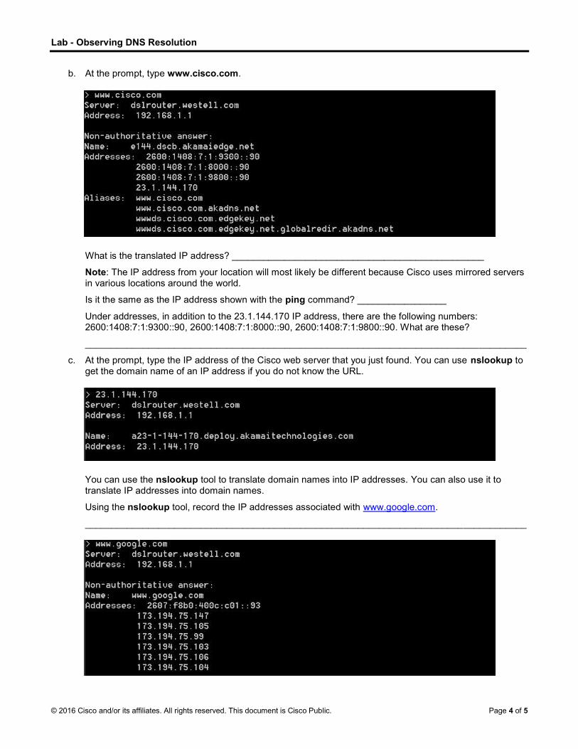
b. At the prompt, type www.cisco.com.
What is the translated IP address? ________________________________________________
Note: The IP address from your location will most likely be different because Cisco uses mirrored servers in various locations around the world.
Is it the same as the IP address shown with the ping command? _________________
Under addresses, in addition to the 23.1.144.170 IP address, there are the following numbers: 2600:1408:7:1:9300::90, 2600:1408:7:1:8000::90, 2600:1408:7:1:9800::90. What are these?
____________________________________________________________________________________
c. At the prompt, type the IP address of the Cisco web server that you just found. You can use nslookup to get the domain name of an IP address if you do not know the URL.
You can use the nslookup tool to translate domain names into IP addresses. You can also use it to translate IP addresses into domain names.
Using the nslookup tool, record the IP addresses associated with www.google.com.
____________________________________________________________________________________

Lab - Observing DNS Resolution
© 2016 Cisco and/or its affiliates. All rights reserved. This document is Cisco Public. Page 5 of 5
Part 3: Observe DNS Lookup Using the nslookup Command on Mail Servers
a. At the prompt, type set type=mx to use nslookup to identify mail servers.
b. At the prompt, type cisco.com.
A fundamental principle of network design is redundancy (more than one mail server is configured). In this way, if one of the mail servers is unreachable, then the computer making the query tries the second mail server. Email administrators determine which mail server is contacted first by using MX preference (see above image). The mail server with the lowest MX preference is contacted first. Based upon the output above, which mail server will be contacted first when the email is sent to cisco.com?
____________________________________________________________________________________
c. At the nslookup prompt, type exit to return to the regular PC command prompt.
d. At the PC command prompt, type ipconfig /all.
e. Write the IP addresses of all the DNS servers that your school uses.
____________________________________________________________________________________
Reflection
What is the fundamental purpose of DNS?
_______________________________________________________________________________________
_______________________________________________________________________________________
_______________________________________________________________________________________

© 2016 Cisco and/or its affiliates. All rights reserved. This document is Cisco Public. Page 1 of 8
Lab - Examining Telnet and SSH in Wireshark
Topology
Addressing Table
Device Interface IP Address Subnet Mask Default Gateway
R1 G0/1 192.168.1.1 255.255.255.0 N/A
PC-A NIC 192.168.1.3 255.255.255.0 192.168.1.1
Objectives
Part 1: Configure the Devices for SSH Access
Part 2: Examine a Telnet Session with Wireshark
Part 3: Examine a SSH Session with Wireshark
Background / Scenario
In this lab, you will configure a router to accept SSH connectivity, and use Wireshark to capture and view Telnet and SSH sessions. This will demonstrate the importance of encryption with SSH.
Note: The routers used with CCNA hands-on labs are Cisco 1941 Integrated Services Routers (ISRs) with Cisco IOS Release 15.2(4)M3 (universalk9 image). The switches used are Cisco Catalyst 2960s with Cisco IOS Release 15.0(2) (lanbasek9 image). Other routers, switches, and Cisco IOS versions can be used. Depending on the model and Cisco IOS version, the commands available and output produced might vary from what is shown in the labs. Refer to the Router Interface Summary Table at the end of this lab for the correct interface identifiers.
Note: Make sure that the routers and switches have been erased and have no startup configurations. If you are unsure, contact your instructor.
Required Resources
1 Router (Cisco 1941 with Cisco IOS Release 15.2(4)M3 universal image or comparable)
1 PC (Windows 7 or 8 with terminal emulation program, such as Tera Term, and Wireshark installed)
Console cables to configure the Cisco IOS devices via the console ports
Ethernet cables as shown in the topology
Part 1: Configure the Devices for SSH Access
In Part 1, you will set up the network topology and configure basic settings, such as the interface IP addresses, device access, and passwords on the router.

Lab - Examining Telnet and SSH in Wireshark
© 2016 Cisco and/or its affiliates. All rights reserved. This document is Cisco Public. Page 2 of 8
Step 1: Cable the network as shown in the topology.
Step 2: Initialize and reload the router.
Step 3: Configure the basic settings on the router.
a. Console into the router and enable privileged EXEC mode.
b. Enter configuration mode.
c. Configure device name as listed in the Addressing Table.
d. Disable DNS lookup to prevent the router from attempting to translate incorrectly entered commands as though they were host names.
e. Assign class as the privileged EXEC encrypted password.
f. Assign cisco as the console password and enable login.
g. Assign cisco as the VTY password and enable login.
h. Encrypt the plain text passwords.
i. Create a banner that will warn anyone accessing the device that unauthorized access is prohibited.
j. Configure and activate the G0/1 interface using the information contained in the Addressing Table.
Step 4: Configure R1 for SSH access.
a. Configure the domain for the device.
R1(config)# ip domain-name ccna-lab.com
b. Configure the encryption key method.
R1(config)# crypto key generate rsa modulus 1024
c. Configure a local database username.
R1(config)# username admin privilege 15 secret adminpass
d. Enable Telnet and SSH on the VTY lines.
R1(config)# line vty 0 4
R1(config-line)# transport input telnet ssh
e. Change the login method to use the local database for user verification.
R1(config-line)# login local
R1(config-line)# end
Step 5: Save the running configuration to the startup configuration file.
Step 6: Configure PC-A.
a. Configure PC-A with an IP address and subnet mask.
b. Configure a default gateway for PC-A.
Step 7: Verify network connectivity.
Ping R1 from PC-A. If the ping fails, troubleshoot the connection.

Lab - Examining Telnet and SSH in Wireshark
© 2016 Cisco and/or its affiliates. All rights reserved. This document is Cisco Public. Page 3 of 8
Part 2: Examine a Telnet Session with Wireshark
In Part 2, you will use Wireshark to capture and view the transmitted data of a Telnet session on the router. You will use Tera Term to telnet to R1, sign in, and then issue the show run command on the router.
Note: If a Telnet/SSH client software package is not installed on your PC, you must install one before continuing. Two popular freeware Telnet/SSH packages are Tera Term (http://download.cnet.com/Tera-Term/3000-20432_4-75766675.html) and PuTTY (www.putty.org).
Note: Telnet is not available from the command prompt in Windows 7, by default. To enable Telnet for use in the command prompt window, click Start > Control Panel > Programs > Programs and Features > Turn Windows features on or off. Click the Telnet Client check box, and then click OK.
Step 1: Capture data.
a. Start Wireshark.
b. Start capturing data on the LAN interface.
Note: If you are unable to start the capture on the LAN interface, you may need to open Wireshark using the Run as Administrator option.
Step 2: Start a Telnet session to the router.
a. Open Tera Term and select the Telnet Service radio button and in the Host field, enter 192.168.1.1.
What is the default TCP port for Telnet sessions? _________________
b. At the Username: prompt, enter admin and at the Password: prompt, enter adminpass. These prompts are generated because you configured the VTY lines to use the local database with the login local command.

Lab - Examining Telnet and SSH in Wireshark
© 2016 Cisco and/or its affiliates. All rights reserved. This document is Cisco Public. Page 4 of 8
c. Issue the show run command.
R1# show run
d. Enter exit to exit the Telnet session and out of Tera Term.
R1# exit
Step 3: Stop the Wireshark capture.
Step 4: Apply a Telnet filter on the Wireshark capture data.
Step 5: Use the Follow TCP Stream feature in Wireshark to view the Telnet session.
a. Right-click one of the Telnet lines in the Packet list section of Wireshark, and from the drop-down list, select Follow TCP Stream.

Lab - Examining Telnet and SSH in Wireshark
© 2016 Cisco and/or its affiliates. All rights reserved. This document is Cisco Public. Page 5 of 8
b. The Follow TCP Stream window displays the data for your Telnet session with the router. The entire session is displayed in clear text, including your password. Notice that the username and show run command that you entered are displayed with duplicate characters. This is caused by the echo setting in Telnet to allow you to view the characters that you type on the screen.
c. After you have finished reviewing your Telnet session in the Follow TCP Stream window, click Close.
Part 3: Examine an SSH Session with Wireshark
In Part 4, you will use the Tera Term software to establish an SSH session with the router. Wireshark will be used to capture and view the data of this SSH session.
Step 1: Open Wireshark and start capturing data on the LAN interface.
Step 2: Start an SSH session on the router.
a. Open Tera Term and enter the G0/1 interface IP address of R1 in the Host: field of the Tera Term: New Connection window. Ensure that the SSH radio button is selected and then click OK to connect to the router.

Lab - Examining Telnet and SSH in Wireshark
© 2016 Cisco and/or its affiliates. All rights reserved. This document is Cisco Public. Page 6 of 8
What is the default TCP port used for SSH sessions? __________________
b. The first time you establish a SSH session to a device, a SECURITY WARNING is generated to let you know that you have not connected to this device before. This message is part of the authentication process. Read the security warning and click Continue.

Lab - Examining Telnet and SSH in Wireshark
© 2016 Cisco and/or its affiliates. All rights reserved. This document is Cisco Public. Page 7 of 8
c. In the SSH Authentication window, enter admin for the username and adminpass for the passphrase. Click OK to sign into the router.
d. You have established an SSH session on the router. The Tera Term software looks very similar to a command window. At the command prompt, issue the show run command.
e. Exit the SSH session by issuing the exit command.
R1# exit
Step 3: Stop the Wireshark capture.
Step 4: Apply an SSH filter on the Wireshark Capture data.

Lab - Examining Telnet and SSH in Wireshark
© 2016 Cisco and/or its affiliates. All rights reserved. This document is Cisco Public. Page 8 of 8
Step 5: Use the Follow TCP Stream feature in Wireshark to view the SSH session.
a. Right-click one of the SSHv2 lines in the Packet list section of Wireshark, and in the drop-down list, select the Follow TCP Stream option.
b. Examine the Follow TCP Stream window of your SSH session. The data has been encrypted and is unreadable. Compare the data in your SSH session to the data of your Telnet session.
Why is SSH preferred over Telnet for remote connections?
____________________________________________________________________________________
____________________________________________________________________________________
c. After examining your SSH session, click Close.
d. Close Wireshark.
Reflection
How would you provide multiple users, each with their own username, access to a network device?
_______________________________________________________________________________________

© 2016 Cisco and/or its affiliates. All rights reserved. This document is Cisco Public. Page 1 of 6
Lab Securing Network Devices
Topology
Addressing Table
Device Interface IP Address Subnet Mask Default Gateway
R1 G0/1 192.168.1.1 255.255.255.0 N/A
S1 VLAN 1 192.168.1.11 255.255.255.0 192.168.1.1
PC-A NIC 192.168.1.3 255.255.255.0 192.168.1.1
Objectives
Part 1: Configure Basic Device Settings
Part 2: Configure Basic Security Measures on the Router
Part 3: Configure Basic Security Measures on the Switch
Part 1: Configure Basic Device Settings
In Part 1, you will set up the network topology and configure basic settings, such as the interface IP addresses, device access, and passwords on the devices.
Step 1: Cable the network as shown in the topology.
Attach the devices shown in the topology and cable as necessary.
Step 2: Initialize and reload the router and switch.
Step 3: Configure the router and switch.
a. Console into the device and enable privileged EXEC mode.
b. Assign the device name according to the Addressing Table.
c. Disable DNS lookup to prevent the router from attempting to translate incorrectly entered commands as though they were hostnames.
d. Assign class as the privileged EXEC encrypted password.
e. Assign cisco as the console password and enable login.
f. Assign cisco as the VTY password and enable login.
g. Create a banner that warns anyone accessing the device that unauthorized access is prohibited.
h. Configure and activate the G0/1 interface on the router using the information contained in the Addressing Table.

Lab Securing Network Devices
© 2016 Cisco and/or its affiliates. All rights reserved. This document is Cisco Public. Page 2 of 6
i. Configure the default SVI on the switch with the IP address information according to the Addressing Table.
j. Save the running configuration to the startup configuration file.
Part 2: Configure Basic Security Measures on the Router
Step 1: Encrypt the clear text passwords.
R1(config)# service password-encryption
Step 2: Strengthen passwords.
An administrator should ensure that passwords meet the standard guidelines for strong passwords. These guidelines could include combining letters, numbers and special characters in the password and setting a minimum length.
Note: Best practice guidelines require the use of strong passwords, such as those shown here, in a production environment. However, the other labs in this course use the cisco and class passwords for ease in performing the labs.
a. Change the privileged EXEC encrypted password to meet guidelines.
R1(config)# enable secret Enablep@55
b. Require that a minimum of 10 characters be used for all passwords.
R1(config)# security passwords min-length 10
Step 3: Enable SSH connections.
a. Assign the domain name as CCNA-lab.com.
R1(config)# ip domain-name CCNA-lab.com
b. Create a local user database entry to use when connecting to the router via SSH. The password should meet strong password standards, and the user should have user EXEC access. If privilege level is not specified in the command, the user will have user EXEC (level 15) access by default.
R1(config)# username SSHadmin privilege 1 secret Admin1p@55
c. Configure the transport input for the VTY lines so that they accept SSH connections, but do not allow Telnet connections.
R1(config)# line vty 0 4
R1(config-line)# transport input ssh
d. The VTY lines should use the local user database for authentication.
R1(config-line)# login local
R1(config-line)# exit
e. Generate a RSA crypto key using a modulus of 1024 bits.
R1(config)# crypto key generate rsa modulus 1024
Step 4: Secure the console and VTY lines.
a. You can set the router to log out of a connection that has been idle for a specified time. If a network administrator was logged into a networking device and was suddenly called away, this command automatically logs the user out after the specified time. The following commands cause the line to log out after five minutes of inactivity.

Lab Securing Network Devices
© 2016 Cisco and/or its affiliates. All rights reserved. This document is Cisco Public. Page 3 of 6
R1(config)# line console 0
R1(config-line)# exec-timeout 5 0
R1(config-line)# line vty 0 4
R1(config-line)# exec-timeout 5 0
R1(config-line)# exit
R1(config)#
b. The following command impedes brute force login attempts. The router blocks login attempts for 30 seconds if someone fails two attempts within 120 seconds. This timer is set especially low for the purpose of this lab.
R1(config)# login block-for 30 attempts 2 within 120
What does the 2 within 120 mean in the above command?
____________________________________________________________________________________
What does the block-for 30 mean in the above command?
____________________________________________________________________________________
Step 5: Verify that all unused ports are disabled.
Router ports are disabled by default, but it is always prudent to verify that all unused ports are in an administratively down state. This can be quickly checked by issuing the show ip interface brief command. Any unused ports that are not in an administratively down state should be disabled using the shutdown command in interface configuration mode.
R1# show ip interface brief Interface IP-Address OK? Method Status Protocol
Embedded-Service-Engine0/0 unassigned YES NVRAM administratively down down
GigabitEthernet0/0 unassigned YES NVRAM administratively down down
GigabitEthernet0/1 192.168.1.1 YES manual up up
Serial0/0/0 unassigned YES NVRAM administratively down down
Serial0/0/1 unassigned YES NVRAM administratively down down
R1#
Step 6: Verify that your security measures have been implemented correctly.
a. Use Tera Term to telnet to R1.
Does R1 accept the Telnet connection? Explain.
____________________________________________________________________________________
____________________________________________________________________________________
b. Use Tera Term to SSH to R1.
Does R1 accept the SSH connection? __________
c. Intentionally mistype the user and password information to see if login access is blocked after two attempts.
What happened after you failed to login the second time?
____________________________________________________________________________________
____________________________________________________________________________________
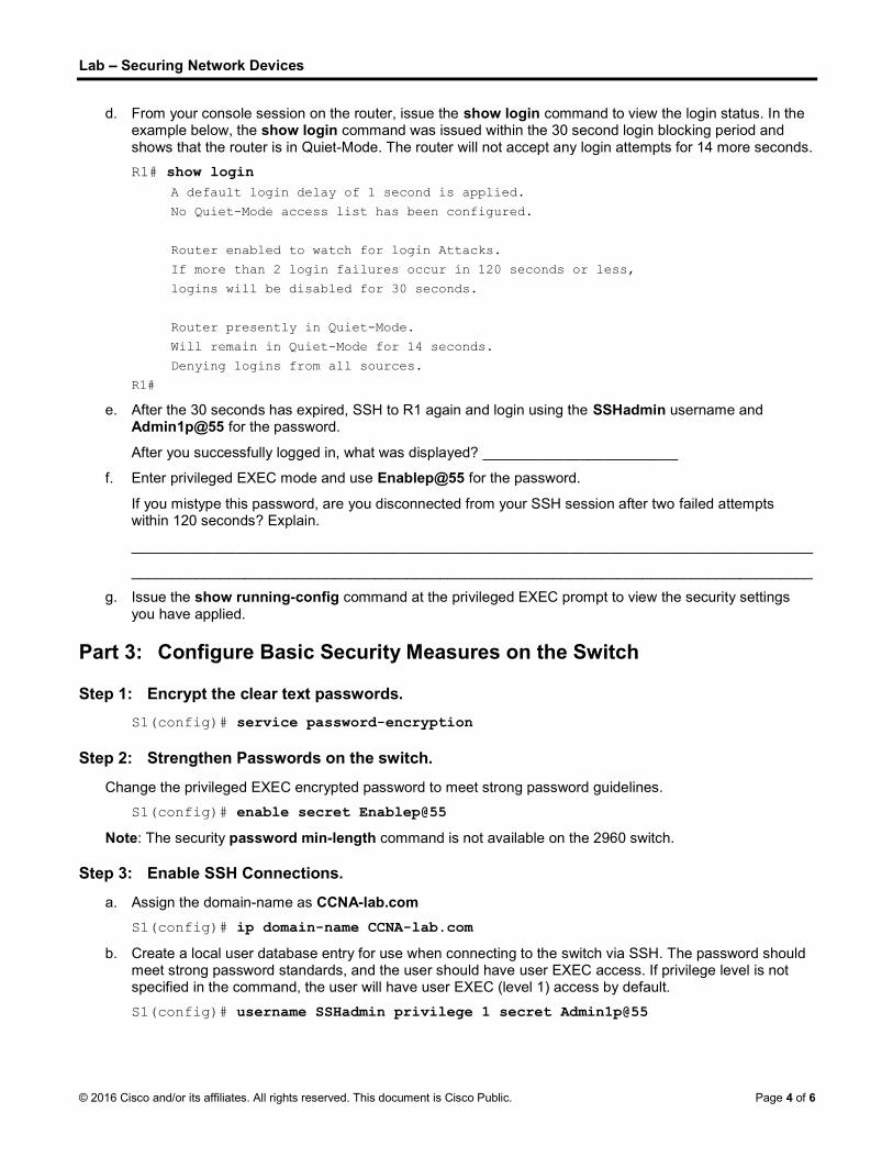
Lab Securing Network Devices
© 2016 Cisco and/or its affiliates. All rights reserved. This document is Cisco Public. Page 4 of 6
d. From your console session on the router, issue the show login command to view the login status. In the example below, the show login command was issued within the 30 second login blocking period and shows that the router is in Quiet-Mode. The router will not accept any login attempts for 14 more seconds.
R1# show login A default login delay of 1 second is applied.
No Quiet-Mode access list has been configured.
Router enabled to watch for login Attacks.
If more than 2 login failures occur in 120 seconds or less,
logins will be disabled for 30 seconds.
Router presently in Quiet-Mode.
Will remain in Quiet-Mode for 14 seconds.
Denying logins from all sources.
R1#
e. After the 30 seconds has expired, SSH to R1 again and login using the SSHadmin username and Admin1p@55 for the password.
After you successfully logged in, what was displayed? ________________________
f. Enter privileged EXEC mode and use Enablep@55 for the password.
If you mistype this password, are you disconnected from your SSH session after two failed attempts within 120 seconds? Explain.
____________________________________________________________________________________
____________________________________________________________________________________
g. Issue the show running-config command at the privileged EXEC prompt to view the security settings you have applied.
Part 3: Configure Basic Security Measures on the Switch
Step 1: Encrypt the clear text passwords.
S1(config)# service password-encryption
Step 2: Strengthen Passwords on the switch.
Change the privileged EXEC encrypted password to meet strong password guidelines.
S1(config)# enable secret Enablep@55
Note: The security password min-length command is not available on the 2960 switch.
Step 3: Enable SSH Connections.
a. Assign the domain-name as CCNA-lab.com
S1(config)# ip domain-name CCNA-lab.com
b. Create a local user database entry for use when connecting to the switch via SSH. The password should meet strong password standards, and the user should have user EXEC access. If privilege level is not specified in the command, the user will have user EXEC (level 1) access by default.
S1(config)# username SSHadmin privilege 1 secret Admin1p@55

Lab Securing Network Devices
© 2016 Cisco and/or its affiliates. All rights reserved. This document is Cisco Public. Page 5 of 6
c. Configure the transport input for the VTY lines to allow SSH connections but not allow Telnet connections.
S1(config)# line vty 0 15
S1(config-line)# transport input ssh
d. The VTY lines should use the local user database for authentication.
S1(config-line)# login local
S1(config-line)# exit
e. Generate an RSA crypto key using a modulus of 1024 bits.
S1(config)# crypto key generate rsa modulus 1024
Step 4: Secure the console and VTY lines.
a. Configure the switch to log out a line that has been idle for 10 minutes.
S1(config)# line console 0
S1(config-line)# exec-timeout 10 0
S1(config-line)# line vty 0 15
S1(config-line)# exec-timeout 10 0
S1(config-line)# exit
S1(config)#
b. To impede brute force login attempts, configure the switch to block login access for 30 seconds if there are 2 failed attempts within 120 seconds. This timer is set especially low for the purpose of this lab.
S1(config)# login block-for 30 attempts 2 within 120
S1(config)# end
Step 5: Verify all unused ports are disabled.
Switch ports are enabled, by default. Shut down all ports that are not in use on the switch.
a. You can verify the switch port status using the show ip interface brief command.
S1# show ip interface brief Interface IP-Address OK? Method Status Protocol
Vlan1 192.168.1.11 YES manual up up
FastEthernet0/1 unassigned YES unset down down
FastEthernet0/2 unassigned YES unset down down
FastEthernet0/3 unassigned YES unset down down
FastEthernet0/4 unassigned YES unset down down
FastEthernet0/5 unassigned YES unset up up
FastEthernet0/6 unassigned YES unset up up
FastEthernet0/7 unassigned YES unset down down
FastEthernet0/8 unassigned YES unset down down
FastEthernet0/9 unassigned YES unset down down
FastEthernet0/10 unassigned YES unset down down
FastEthernet0/11 unassigned YES unset down down
FastEthernet0/12 unassigned YES unset down down
S1#
b. Use the interface range command to shut down multiple interfaces at a time.
S1(config)# interface range f0/1 4 , f0/7-24 , g0/1-2

Lab Securing Network Devices
© 2016 Cisco and/or its affiliates. All rights reserved. This document is Cisco Public. Page 6 of 6
S1(config-if-range)# shutdown
S1(config-if-range)# end
S1#
c. Verify that all inactive interfaces have been administratively shut down.
S1# show ip interface brief Interface IP-Address OK? Method Status Protocol
Vlan1 192.168.1.11 YES manual up up
FastEthernet0/1 unassigned YES unset administratively down down
FastEthernet0/2 unassigned YES unset administratively down down
FastEthernet0/3 unassigned YES unset administratively down down
FastEthernet0/4 unassigned YES unset administratively down down
FastEthernet0/5 unassigned YES unset up up
FastEthernet0/6 unassigned YES unset up up
FastEthernet0/7 unassigned YES unset administratively down down
FastEthernet0/8 unassigned YES unset administratively down down
FastEthernet0/9 unassigned YES unset administratively down down
FastEthernet0/10 unassigned YES unset administratively down down
FastEthernet0/11 unassigned YES unset administratively down down
FastEthernet0/12 unassigned YES unset administratively down down
S1#
Step 6: Verify that your security measures have been implemented correctly.
a. Verify that Telnet has been disabled on the switch.
b. SSH to the switch and intentionally mistype the user and password information to see if login access is blocked.
c. After the 30 seconds has expired, SSH to S1 again and log in using the SSHadmin username and Admin1p@55 for the password.
Did the banner appear after you successfully logged in? __________
d. Enter privileged EXEC mode using Enablep@55 as the password.
e. Issue the show running-config command at the privileged EXEC prompt to view the security settings you have applied.
Reflection
1. The password cisco command was entered for the console and VTY lines in your basic configuration in Part 1. When is this password used after the best practice security measures have been applied?
_______________________________________________________________________________________
_______________________________________________________________________________________
_______________________________________________________________________________________
2. Are preconfigured passwords shorter than 10 characters affected by the security passwords min-length 10 command?
_______________________________________________________________________________________
_______________________________________________________________________________________

© 2016 Cisco and/or its affiliates. All rights reserved. This document is Cisco Public. Page 1 of 7
Lab Using the CLI to Gather Network Device Information
Topology
Addressing Table
Device Interface IP Address Subnet Mask Default Gateway
R1 G0/1 192.168.1.1 255.255.255.0 N/A
Lo0 209.165.200.225 255.255.255.224 N/A
S1 VLAN 1 192.168.1.11 255.255.255.0 192.168.1.1
PC-A NIC 192.168.1.3 255.255.255.0 192.168.1.1
Objectives
Part 1: Set Up Topology and Initialize Devices
Part 2: Configure Devices and Verify Connectivity
Part 3: Gather Network Device Information
Background / Scenario
Documenting a working network is one of the most important tasks a network professional can perform. Having proper documentation of IP addresses, model numbers, IOS versions, ports used, and testing security, can go a long way in helping to troubleshoot a network.
In this lab, you will build a small network, configure the devices, add some basic security, and then document the configurations by issuing various commands on the router, switch and PC to gather your information.
Note: The routers used with CCNA hands-on labs are Cisco 1941 Integrated Services Routers (ISRs) with Cisco IOS Release 15.2(4)M3 (universalk9 image). The switches used are Cisco Catalyst 2960s with Cisco IOS Release 15.0(2) (lanbasek9 image). Other routers, switches, and Cisco IOS versions can be used. Depending on the model and Cisco IOS version, the commands available and output produced might vary from what is shown in the labs. Refer to the Router Interface Summary Table at the end of this lab for the correct interface identifiers.
Note: Make sure that the routers and switches have been erased and have no startup configurations. If you are unsure, contact your instructor.
Required Resources
1 Router (Cisco 1941 with Cisco IOS Release 15.2(4)M3 universal image or comparable)
1 Switch (Cisco 2960 with Cisco IOS Release 15.0(2) lanbasek9 image or comparable)

Lab Using the CLI to Gather Network Device Information
© 2016 Cisco and/or its affiliates. All rights reserved. This document is Cisco Public. Page 2 of 7
1 PC (Windows 7 or 8 with terminal emulation program, such as Tera Term)
Console cables to configure the Cisco IOS devices via the console ports
Ethernet cables as shown in the topology
Part 1: Set Up the Topology and Initialize Devices
In Part 1, you will set up the network topology, clear any configurations if necessary, and configure basic settings on the router and switch.
Step 1: Cable the network as shown in the topology.
a. Attach the devices as shown in the topology and cable as necessary.
b. Power on all devices in the topology.
Step 2: Initialize and reload the router and the switch.
Part 2: Configure Devices and Verify Connectivity
In Part 2, you will set up the network topology and configure basic settings on the router and switch. Refer to the topology and Addressing Table at the beginning of this lab for device names and address information.
Step 1: Configure the IPv4 address for the PC.
Configure the IPv4 address, subnet mask, and default gateway address for PC-A based on the Addressing Table.
Step 2: Configure the router.
a. Console into the router and enter privileged EXEC mode.
b. Set the correct time on the router.
c. Enter global configuration mode.
1) Assign a device name to the router based on the topology and Addressing Table.
2) Disable DNS lookup.
3) Create a MOTD banner that warns anyone accessing the device that unauthorized access is prohibited.
4) Assign class as the privileged EXEC encrypted password.
5) Assign cisco as the console password and enable console login access.
6) Encrypt clear text passwords.
7) Create a domain name of cisco.com for SSH access.
8) Create a user named admin with a secret password of cisco for SSH access.
9) Generate a RSA modulus key. Use 1024 for the number of bits.
d. Configure VTY line access.
1) Use the local database for authentication for SSH.
2) Enable SSH only for login access.

Lab Using the CLI to Gather Network Device Information
© 2016 Cisco and/or its affiliates. All rights reserved. This document is Cisco Public. Page 3 of 7
e. Return to global configuration mode.
1) Create the Loopback 0 interface and assign the IP address based on the Addressing Table.
2) Configure and activate interface G0/1 on the router.
3) Configure interface descriptions for G0/1 and L0.
4) Save the running configuration file to the startup configuration file.
Step 3: Configure the switch.
a. Console into the switch and enter privileged EXEC mode.
b. Set the correct time on the switch.
c. Enter global configuration mode.
1) Assign a device name on the switch based on the topology and Addressing Table.
2) Disable DNS lookup.
3) Create a MOTD banner that warns anyone accessing the device that unauthorized access is prohibited.
4) Assign class as the privileged EXEC encrypted password.
5) Encrypt the clear text passwords.
6) Create a domain name of cisco.com for SSH access.
7) Create a user named admin with a secret password of cisco for SSH access.
8) Generate an RSA key. Use 1024 for the number of bits.
9) Create and activate an IP address on the switch based on the topology and Addressing Table.
10) Set the default gateway on the switch.
11) Assign cisco as the console password and enable console login access.
d. Configure VTY line access.
1) Use local database for authentication for SSH.
2) Enable SSH only for login access.
3) Save the running configuration file to the startup configuration file.
e. Enter proper mode to configure interface descriptions for F0/5 and F0/6.
Step 4: Verify network connectivity.
a. From a command prompt on PC-A, ping the S1 VLAN 1 IP address. Troubleshoot your physical and logical configurations if the pings were not successful.
b. From the PC-A command prompt, ping your default gateway IP address on R1. Troubleshoot your physical and logical configurations if the pings were not successful.
c. From the PC-A command prompt, ping the loopback interface on R1. Troubleshoot your physical and logical configurations if the pings were not successful.
d. Console back into the switch and ping the G0/1 IP address on R1. Troubleshoot your physical and logical configurations if the pings were not successful.

Lab Using the CLI to Gather Network Device Information
© 2016 Cisco and/or its affiliates. All rights reserved. This document is Cisco Public. Page 4 of 7
Part 3: Gather Network Device Information
In Part 3, you will use a variety of commands to gather information about the devices on your network, as well as some performance characteristics. Network documentation is a very important component of managing your network. Documentation of both physical and logical topologies is important, as is verifying platform models and IOS versions of your network devices. Having knowledge of the proper commands to gather this information is essential for a network professional.
Step 1: Gather information on R1 using IOS commands.
One of the most basic steps is to gather information on the physical device, as well as information on the operating system.
a. Issue the appropriate command to discover the following information:
Router Model: __________________________________
IOS Version: __________________________________
Total RAM: __________________________________
Total NVRAM: __________________________________
Total Flash Memory: __________________________________
IOS Image File: __________________________________
Configuration Register: __________________________________
Technology Package: __________________________________
What command did you issue to gather the information?
_____________________________________________________________
b. Issue the appropriate command to display a summary of important information about the router interfaces. Write down the command and record your results below.
Note: Only record interfaces that have IP addresses.
____________________________________________________________________________________
____________________________________________________________________________________
____________________________________________________________________________________
____________________________________________________________________________________
c. Issue the appropriate command to display the routing table. Write down the command and record your results below.
____________________________________________________________________________________
____________________________________________________________________________________
____________________________________________________________________________________
____________________________________________________________________________________
____________________________________________________________________________________
____________________________________________________________________________________
____________________________________________________________________________________
____________________________________________________________________________________

Lab Using the CLI to Gather Network Device Information
© 2016 Cisco and/or its affiliates. All rights reserved. This document is Cisco Public. Page 5 of 7
d. What command would you use to display the Layer 2 to Layer 3 mapping of addresses on the router? Write down the command and record your results below.
____________________________________________________________________________________
____________________________________________________________________________________
____________________________________________________________________________________
____________________________________________________________________________________
____________________________________________________________________________________
e. What command would you use to see detailed information about all the interfaces on the router or about a specific interface? Write down the command below.
____________________________________________________________________________________
f. Cisco has a very powerful protocol that operates at Layer 2 of the OSI model. This protocol can help you map out how Cisco devices are connected physically, as well as determining model numbers and even IOS versions and IP addressing. What command or commands would you use on router R1 to find out information about switch S1 to help you complete the table below?
Device ID Local
Interface Capability Model # Remote Port ID IP Address IOS Version
g. A very elementary test of your network devices is to see if you can telnet into them. Remember, Telnet is not a secure protocol. It should not be enabled in most cases. Using a Telnet client, such as Tera Term or PuTTY, try to telnet to R1 using the default gateway IP address. Record your results below.
___________________________________________________________________________________
h. From PC-A, test to ensure that SSH is working properly. Using an SSH client, such as Tera Term or PuTTY, SSH into R1 from PC-A. If you get a warning message regarding a different key, click Continue. Log in with the appropriate username and password you created in Part 2. Were you successful?
___________________________________________________________________________________
The various passwords configured on your router should be as strong and protected as possible.
Note: The passwords used for our lab (cisco and class) do not follow the best practices needed for strong passwords. These passwords are used merely for the convenience of performing the labs. By default, the console password and any vty passwords configured would display in clear text in your configuration file.
i. Verify that all of your passwords in the configuration file are encrypted. Write down the command and record your results below.
Command: ________________________________________________
Is the console password encrypted? __________________________
Is the SSH password encrypted? _____________________________
Step 2: Gather information on S1 using IOS commands.
Many of the commands that you used on R1 can also be used with the switch. However, there are some differences with some of the commands.
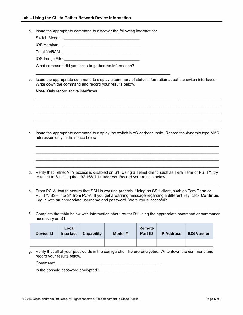
Lab Using the CLI to Gather Network Device Information
© 2016 Cisco and/or its affiliates. All rights reserved. This document is Cisco Public. Page 6 of 7
a. Issue the appropriate command to discover the following information:
Switch Model: __________________________________
IOS Version: __________________________________
Total NVRAM: __________________________________
IOS Image File: __________________________________
What command did you issue to gather the information?
_____________________________________________________________
b. Issue the appropriate command to display a summary of status information about the switch interfaces. Write down the command and record your results below.
Note: Only record active interfaces.
____________________________________________________________________________________
____________________________________________________________________________________
____________________________________________________________________________________
____________________________________________________________________________________
____________________________________________________________________________________
c. Issue the appropriate command to display the switch MAC address table. Record the dynamic type MAC addresses only in the space below.
___________________________________________________________________________________
___________________________________________________________________________________
___________________________________________________________________________________
___________________________________________________________________________________
d. Verify that Telnet VTY access is disabled on S1. Using a Telnet client, such as Tera Term or PuTTY, try to telnet to S1 using the 192.168.1.11 address. Record your results below.
___________________________________________________________________________________
e. From PC-A, test to ensure that SSH is working properly. Using an SSH client, such as Tera Term or PuTTY, SSH into S1 from PC-A. If you get a warning message regarding a different key, click Continue. Log in with an appropriate username and password. Were you successful?
___________________________________________________________________________________
f. Complete the table below with information about router R1 using the appropriate command or commands necessary on S1.
Device Id Local
Interface Capability Model # Remote Port ID IP Address IOS Version
g. Verify that all of your passwords in the configuration file are encrypted. Write down the command and record your results below.
Command: ________________________________________________
Is the console password encrypted? __________________________

Lab Using the CLI to Gather Network Device Information
© 2016 Cisco and/or its affiliates. All rights reserved. This document is Cisco Public. Page 7 of 7
Step 3: Gather information on PC-A.
Using various Windows utility commands, you will gather information on PC-A.
a. From the PC-A command prompt, issue the ipconfig /all command and record your answers below.
What is the PC-A IP address?
____________________________________________________________________________________
What is the PC-A subnet mask?
____________________________________________________________________________________
What is the PC-A default gateway address?
____________________________________________________________________________________
What is the PC-A MAC address?
____________________________________________________________________________________
b. Issue the appropriate command to test the TCP/IP protocol stack with the NIC. What command did you use?
____________________________________________________________________________________
c. Ping the loopback interface of R1 from the PC-A command prompt. Was the ping successful?
____________________________________________________________________________________
d. Issue the appropriate command on PC-A to trace the list of router hops for packets originating from PC-A to the loopback interface on R1. Record the command and output below. What command did you use?
____________________________________________________________________________________
____________________________________________________________________________________
e. Issue the appropriate command on PC-A to find the Layer 2 to Layer 3 address mappings held on your NIC. Record your answers below. Only record answers for the 192.168.1.0/24 network. What command did you use?
____________________________________________________________________________________
____________________________________________________________________________________
____________________________________________________________________________________
____________________________________________________________________________________
Reflection
Why is it important to document your network devices?
_______________________________________________________________________________________
_______________________________________________________________________________________
_______________________________________________________________________________________
_______________________________________________________________________________________
_______________________________________________________________________________________