ccna exploration network fundamentals - … networks/chapter2... · ccna exploration network...
TRANSCRIPT

Source: KC KHOR
Updated: 18/04/20081
CCNA Exploration
Network Fundamentals
Chapter 02
Communicating Over The Network
2
The Elements of Communication Communication begins with a message, or
information, that must be sent from one individual or device to another using many different communication methods.
All of these methods have 3 elements in common:
- message source, or sender
- destination, or receiver
- a channel, media or pathway
3
Communicating The Messages Data is divided into smaller parts during
transmission - Segmentation
The benefits of doing so:
- Many different conversations can be
interleaved on the network. The process used to
interleave the pieces of separate conversations
together on the network is called multiplexing.
- Increase the reliability of network
communications. The separate pieces of each
message need not travel the same pathway across
the network from source to destination

4
Downside of segmentation and multiplexing
- level of complexity is added (process of
addressing, labeling, sending, receiving and etc
are time consuming)
Each segment of the message must go through
a similar process to ensure that it gets to the
correct destination and can be reassembled into
the content of the original message
Various types of devices throughout the network
participate in ensuring that the pieces of the
message arrive reliably at their destination
5
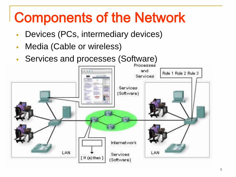
Components of the Network Devices (PCs, intermediary devices)
Media (Cable or wireless)
Services and processes (Software)

6
End Devices and Their Roles
In the context of a network, end devices are referred to as hosts.
A host device is either the sender or receiver
To distinguish one host from another, each host on a network is identified by an address.
A host (sender) uses the address of the destination host to specify where the message should be sent.
Software determines the role of a host. A host can be a client, server or both

7
Intermediary Devices and Their Roles
Examples:
- Network Access Devices (Hubs, switches, and wireless access points)
- Internetworking Devices (routers)
- Communication Servers and Modems
- Security Devices (firewalls)
8
Processes running on the intermediary network devices perform these functions:
- Regenerate and retransmit data signals
- Maintain information about what pathways exist through the network and internetwork
- Notify other devices of errors and communication failures
- Direct data along alternate pathways when there is a link failure
- Classify and direct messages according to QoSpriorities
- Permit or deny the flow of data, based on security settings

9
Network Media Communication across a network is carried on a
medium• 3 types of Media:
- Metallic wires
within cables
- Glass or plastic
fibers (fiber optic
cable)
-Wireless
transmission
10
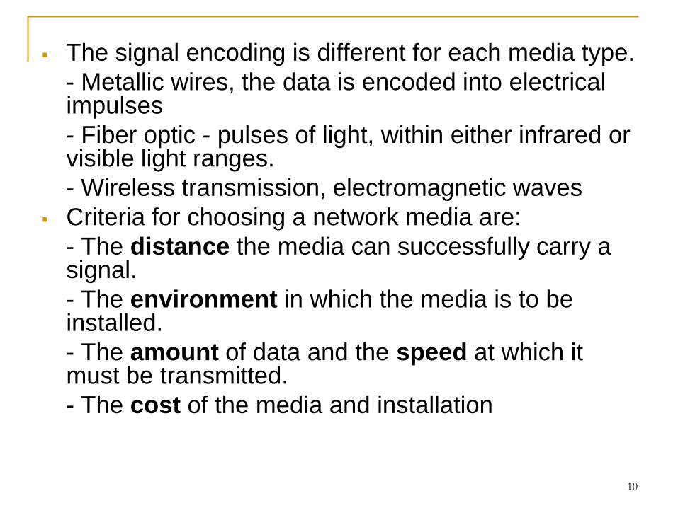
The signal encoding is different for each media type.
- Metallic wires, the data is encoded into electrical impulses
- Fiber optic - pulses of light, within either infrared or visible light ranges.
- Wireless transmission, electromagnetic waves
Criteria for choosing a network media are:
- The distance the media can successfully carry a signal.
- The environment in which the media is to be installed.
- The amount of data and the speed at which it must be transmitted.
- The cost of the media and installation

11
LAN, WAN, Internetworks Local Area Network (LAN) - An individual network usually spans a
single geographical area, providing services and applications to people within a common organizational structure, such as a single business, campus or region
Wide Area Network (WAN)- Individual organizations usually lease connections through a telecommunications service provider network. These networks that connect LANs in geographically separated locations are referred to as Wide Area Networks.
12
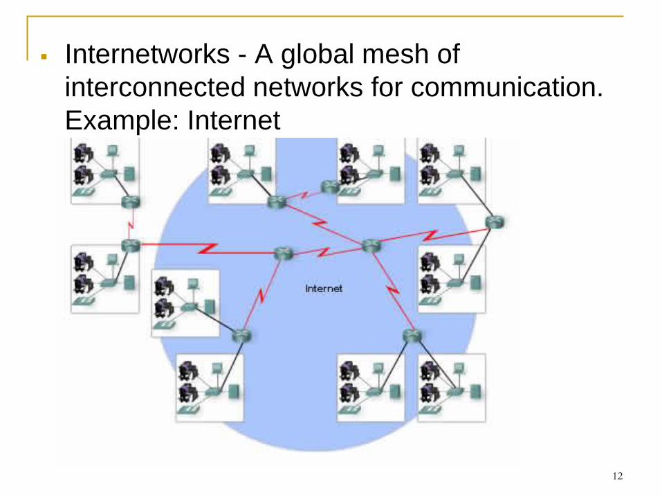
Internetworks - A global mesh of
interconnected networks for communication.
Example: Internet
13
The term intranet is often used to refer to a
private connection of LANs and WANs that
belongs to an organization, and is designed
to be accessible only by the organization's
members, employees, or others with
authorization.
14
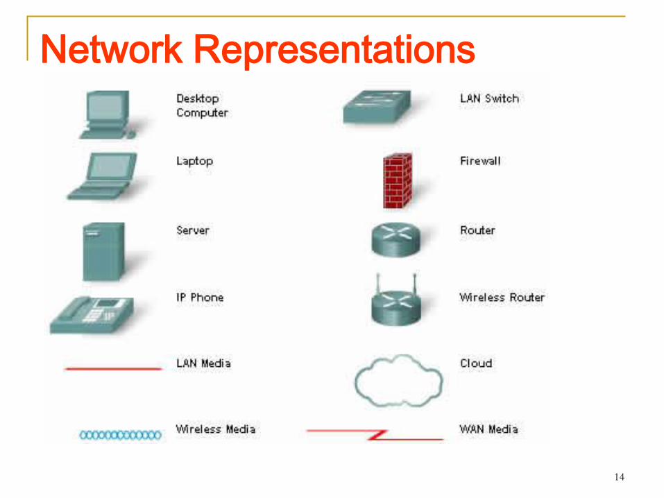
Network Representations
15
- Network Interface Card - A NIC, or LAN adapter,
provides the physical connection to the network at
the PC or other host device. The media connecting
the PC to the networking device plugs directly into
the NIC.
- Physical Port - A connector or outlet on a
networking device where the media is connected to
a host or other networking device.
- Interface - Specialized ports on an internetworking
device that connect to individual networks. Because
routers are used to interconnect networks, the ports
on a router are referred to network interfaces.
16
Rules that Govern Communications Communication in networks is governed by pre-defined rules
called protocols.
A group of inter-related protocols that are necessary to perform a communication function is called a protocol suite. These protocols are implemented in software and hardware that is loaded on each host and network device
Networking protocols suites describe processes such as:
- The format or structure of the message
- The process by which networking devices share information about pathways with other networks
- How and when error and system messages are passed between devices
- The setup and termination of data transfer sessions
Individual protocols in a protocol suite may be vendor-specific and proprietary.

17
Protocol Suites & Industry Standard
Many of the protocols that comprise a protocol suite reference other widely utilized protocols or industry standards
Institute of Electrical and Electronics Engineers (IEEE) or the Internet Engineering Task Force (IETF)
The use of standards in developing and implementing protocols ensures that products from different manufacturers can work together for efficient communications

18
The Interaction of Protocols
Application protocol – HTTP. HTTP defines the content and formatting of the requests and responses exchanged between the client and server
Transport Protocol – TCP. TCP divides the HTTP messages into smaller segments. It is also responsible for controlling the size and rate of message exchange.
Internetwork Protocol – IP. It encapsulating segments into packets, assigning the appropriate addresses, and selecting the best path to the destination host.
Network Access Protocol – Protocols for data link management and the physical transmission of data on the media.
Will learn
more in
TCP/IP
model
19
Using Layer Models To visualize the interaction between various
protocols, it is common to use a layered model.
Benefits of using layered model:
- Assists in protocol design, because protocols that operate at a specific layer have defined information that they act upon and a defined interface to the layers above and below.
- Fosters competition because products from different vendors can work together.
- Prevents technology or capability changes in one layer from affecting other layers above and below.
- Provides a common language to describe networking functions and capabilities.

20
Protocol & Reference Model 2 types of networking models
A protocol model provides a model that closely matches the structure of a particular protocol suite. The hierarchical set of related protocols in a suite typically represents all the functionality required to interface the human network with the data network. Example: TCP/IP model
A reference model provides a common reference for maintaining consistency within all types of network protocols and services. A reference model is not intended to be an implementation specification or to provide a sufficient level of detail to define precisely the services of the network architecture. The primary purpose of a reference model is to aid in clearer understanding of the functions and process involved
Example: OSI model

21
TCP/IP Model

Communication Process
A complete communication process includes these steps:
1. Creation of data at the application layer of the originating source end device
2. Segmentation and encapsulation of data as it passes down the protocol stack in the source end device
3. Generation of the data onto the media at the network access layer of the stack
4. Transportation of the data through the internetwork, which consists of media and any intermediary devices
5. Reception of the data at the network access layer of the destination end device
6. Decapsulation and reassembly of the data as it passes up the stack in the destination device
7. Passing this data to the destination application at the Application layer of the destination end device

23
Protocol Data Units and Data Encapsulation

24
Protocol Data Units and Data Encapsulation
As application data is passed down the protocol
stack on its way to be transmitted across the
network media, various protocols add information to
it at each level.
This is commonly known as the encapsulation
process.
The form that a piece of data takes at any layer is
called a Protocol Data Unit (PDU).
During encapsulation, each succeeding layer
encapsulates the PDU that it receives from the layer
above in accordance with the protocol being used.

25
Protocol Data Units and Data Encapsulation
TCP/IP protocol suite PDUs:
Data – Application Layer PDU
Segment - Transport Layer PDU
Packet - Internetwork Layer PDU
Frame - Network Access Layer PDU
Bits - PDU used when physically transmitting data over
the medium

26
Sending and Receiving Process
When sending messages on a network, the protocol
stack on a host operates from top to bottom.
This process is reversed at the receiving host. The data
is decapsulated as it moves up the stack toward the end
user application.

27
OSI – The Application Layer Performs services
for the applications used by end users.
28
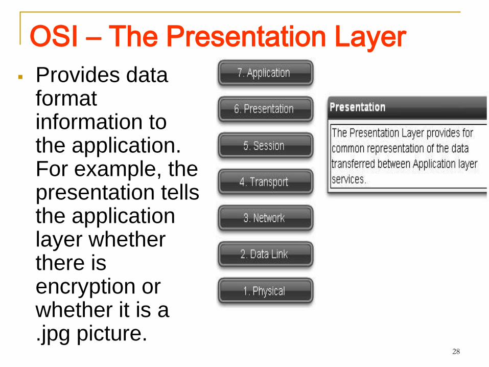
OSI – The Presentation Layer
Provides data format information to the application. For example, the presentation tells the application layer whether there is encryption or whether it is a .jpg picture.

29
OSI – The Session Layer Manages
sessions between users.

30
OSI – The Transport Layer
Defines data segments and numbers them at the source, transfers the data, and reassembles the data at the destination.
31
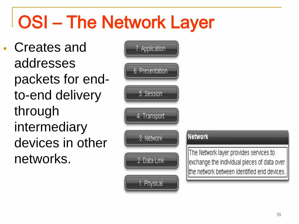
OSI – The Network Layer
Creates and
addresses
packets for end-
to-end delivery
through
intermediary
devices in other
networks.

32
OSI – The Data Link Layer
Creates and
addresses frames
for host-to-host
delivery on the
local LANs and
between WAN
devices.

33
OSI – The Physical Layer
Transmits binary
data over the
media between
devices. Physical
layer protocols
define media
specifications.

34
Comparing OSI model with TCP/IP Model--Both have application
layers, though they include
very different services
--Both have comparable
transport and network
(Internet) layers
--TCP/IP combines the presentation and session layer issues into its application layer
--TCP/IP combines the OSI data link and physical layers into one layer
--TCP/IP appears simpler because it has fewer layers

35
Addressing in the Network
There are various types of addresses that must be included to successfully deliver the data from a source application running on one host to the correct destination application running on another
36
Getting Data to the End Device
The host physical address, is contained in the header of the Layer 2 PDU, called a frame.
Layer 2 is concerned with the delivery of messages on a single local network.
The Layer 2 address is unique on the local network and represents the address of the end device on the physical media.
In a LAN using Ethernet, this address is called the Media Access Control (MAC) address.
When two end devices communicate on the local Ethernet network, the frames that are exchanged between them contain the destination and source MAC addresses.
Once a frame is successfully received by the destination host, the Layer 2 address information is removed as the data is decapsulated and moved up the protocol stack to Layer 3.

KC KHOR, Multimedia Univ. Cyberjaya37
Getting the Data Through the Internetwork Layer 3 protocols are primarily designed to move data
from one local network to another local networkwithin an internetwork.
Layer 3 addresses must include identifiers that enable intermediary network devices to locate hosts on different networks
At the boundary of each local network, an intermediary network device, usually a router, decapsulates the frame to read the destination host address contained in the header of the packet, the Layer 3 PDU
Routers use the network identifier portion of this address to determine which path to use to reach the destination host.
38
Getting Data to the Right Application
At Layer 4, information contained in the PDU header identify the specific process or service running on the destination host device that will act on the data being delivered.
Hosts, whether they are clients or servers on the Internet, can run multiple network applications simultaneously.
Each application or service is represented at Layer 4 by a port number.
A unique dialogue between devices is identified with a pair of Layer 4 source and destination port numbers that are representative of the two communicating applications.