ccl400 series ac-dc power supplies · line regulation 0.5 % ... transistor off: input & output...
TRANSCRIPT

CCL400 Series AC-DC Power Supplies
The universal AC input CCL400 provides 400W of convection cooled output power over the
temperature range -40°C to +50°C with derating to +70°C. The temperature range can be
extended by the use of conduction cooling to the full 400W at +70°C. Approved for IT and Medical
and with a feature set including a 5V standby output, <0.5W standby power, power fail and inhibit
signals the CCL400 is ideal for a wide range of applications where fan cooling is not desirable.
• 400 W Convection-cooled
• Conduction Cooling For Higher Ambient Operation
• 94% Efficiency
• 85 VAC to 264 VAC Input
• 5V Standby
• <1W Standby Power
• IT & Medical Safety Approvals
• Power Fail & Inhibit Signals
• 3 Year Warranty
400 Watts
Dimensions:
CCL400:7.00 x 3.95 x 1.57” (178 x 100 x 40 mm)CCL400-C:7.39 x 4.04 x 1.92” (189.9 x 107.3 x 48.9 mm)
www.xppower.com1
Models & Ratings
Notes1. Add suffix ‘-C’ for cover version e.g. CCL400PS24-C2. Add suffix ‘-S’ for a right angled input screw terminal connector e.g. CCL400PS24-S or CCL400PS24-CS.
Output Voltage 1 Output Current V1 Standby Supply V2 Output Power Model Number (1,2)
12 V 33.3 A 5.0 V / 0.5 A 400 W CCL400PS1224 V 16.6 A 5.0 V / 0.5 A 400 W CCL400PS2430 V 13.3 A 5.0 V / 0.5 A 400 W CCL400PS3048 V 8.3 A 5.0 V / 0.5 A 400 W CCL400PS48
Mechanical Details
A
-VE
+VE
7.12 (180.86)
1.57(39.88)
Output Voltage Control
Output TerminalM4 Screw in 2 positionsTorque to 8lbs-in (90 cNm) max.
7.0 (177.8)
2 x M3 max depth 0.16 (4.0)
6.6 (167.64)0.4 (10.16)
1.0(25.4)
3.95(100.33)
2.45(62.23)
0.75 (19.05)
0.9 (22.86) 5.2 (132.08)
4 x M3 max depth 0.12 (3.0)
Pin 1
Pin 9
Input Connector CON1
123
Pin 10
Pin 2
Detail A, Scale 1:1Signals Connector CON410 way JST B10B-PHDSS
6.6 (167.64)1.0
(25.4)
0.4 (10.16)
2 x M3 max depth 0.16 (4.0)

CCL400 Series
www.xppower.com 2
AC-DC Power Supplies
Input
OutputCharacteristic Minimum Typical Maximum Units Notes & Conditions
Output Voltage 12 48 VDC See Models and Ratings table
Initial Set Accuracy ±0.5 % 50% load, 115/230 VAC
Output Voltage Adjustment ±3 %
Minimum Load 0 A
Start Up Delay 1.5 2.0 s 115/230 VAC full load from input AC turn on
Hold Up Time 30 ms
Drift ±0.2 % After 20 min warm up
Line Regulation 0.5 %
Load Regulation 0.5 %
Transient Response <4 % Recovery within 1% in less than 500 µs for a 50-75%-50% load change
Ripple & Noise 1 % pk-pk 20 MHz bandwidth
Overvoltage Protection 115 140 % Vnom DC. Output 1, recycle input to reset
Overload Protection 110 150 % Trip & Restart characteristic V1
Short Circuit Protection Shutdown and auto recovery
Temperature Coefficient 0.05 %/˚C
Overtemperature Protection Shutdown and auto recovery
Characteristic Minimum Typical Maximum Units Notes & Conditions
Input Voltage - Operating 85 115/230 264 VAC Derate output power < 100 VAC for convection cooling or<90 VAC for conduction cooling. See fig. 1
Input Voltage - Fault Condition 300 VAC 5 seconds max
Input Frequency 47 50/60 63 Hz Agency approval, 47-63 Hz
Power Factor >0.95EN61000-3-2 class A compliant
EN61000-3-2 class C for loads ≥10%
Input Current - Full Load 3.8/1.9 A 115/230 VAC
No Load Input Power 1 W All models, when inhibit activated
Inrush Current 35 60 A 230 VAC
Earth Leakage Current 90/180 250 µA Typ. 115/230 VAC 50 Hz, Max 264 VAC 60 Hz
Input Protection F10.0 A 250 V internal fuse in both AC lines
Input Voltage Derating
Figure 1
85 90 100 2640
Input Voltage (V)
100
200
300
400
Conduction Cooled with and without cover
Convection Cooled without cover
Out
put
Pow
er (W
)
350
Convection Cooled with cover

CCL400 Series
www.xppower.com
AC-DC Power Supplies
3
GeneralCharacteristic Minimum Typical Maximum Units Notes & Conditions
Efficiency 93-94 % 230 VAC full load
Isolation: Input to OutputInput to GroundOutput to Ground
4000 VAC 2 x MOPP
1500 VAC 1 X MOPP
500 VDC
Switching Frequency
60 300 kHz PFC
75 kHz Main converter
70 kHz Standby
Power Density 9.1 W/in3
Mean Time Between Failure 172 kHrs MIL-HDBK-217F, Notice 2 +25 °C GB
Weight2.12 (960)
lb (g)CCL400PSxx
2.46 (1115) CCL400PSxx-C
Efficiency Vs Load
Figure 212 V Models
Figure 324 V Models
Figure 448 V Models
0.00% 10.00% 20.00% 30.00% 40.00% 50.00% 60.00% 70.00% 80.00% 90.00%
100.00%
20% 30% 40% 50% 60% 70% 80% 90% 100%
Effic
iency
Load
115V
230V
0.00% 10.00% 20.00% 30.00% 40.00% 50.00% 60.00% 70.00% 80.00% 90.00%
100.00%
20% 30% 40% 50% 60% 70% 80% 90% 100%
Effic
iency
Load
115V
230V
0.00% 10.00% 20.00% 30.00% 40.00% 50.00% 60.00% 70.00% 80.00% 90.00%
100.00%
20% 30% 40% 50% 60% 70% 80% 90% 100%
Effic
iency
Load
115V
230V
CCL400 Series
www.xppower.com 4
AC-DC Power Supplies
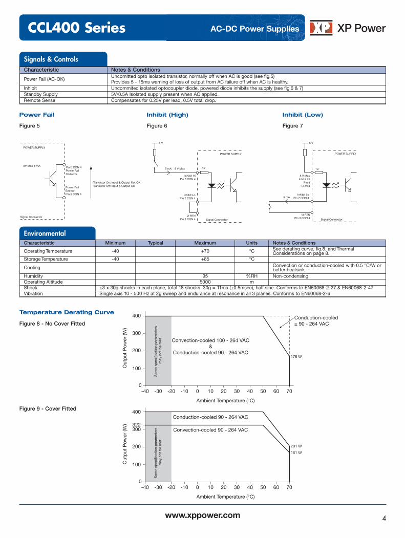
Signals & ControlsCharacteristic Notes & Conditions
Power Fail (AC-OK) Uncomitted opto isolated transistor, normally off when AC is good (see fig.5)Provides 5 - 15ms warning of loss of output from AC failure off when AC is healthy.
Inhibit Uncommited isolated optocoupler diode, powered diode inhibits the supply (see fig.6 & 7)Standby Supply 5V/0.5A Isolated supply present when AC applied.Remote Sense Compensates for 0.25V per lead, 0.5V total drop.
Figure 5
Power Fail
Figure 6
Inhibit (High)
Figure 7
Inhibit (Low)
EnvironmentalCharacteristic Minimum Typical Maximum Units Notes & Conditions
Operating Temperature -40 +70 °C See derating curve, fig.8. and ThermalConsiderations on page 8.
Storage Temperature -40 +85 °C
Cooling Convection or conduction-cooled with 0.5 °C/W orbetter heatsink
Humidity 95 %RH Non-condensingOperating Altitude 5000 mShock ±3 x 30g shocks in each plane, total 18 shocks. 30g = 11ms (±0.5msec), half sine. Conforms to EN60068-2-27 & EN60068-2-47Vibration Single axis 10 - 500 Hz at 2g sweep and endurance at resonance in all 3 planes. Conforms to EN60068-2-6
-40 -300
Ambient Temperature (°C)
Convection-cooled 100 - 264 VAC&
Conduction-cooled 90 - 264 VAC
Som
e sp
ecifi
catio
n p
aram
eter
s m
ay n
ot b
e m
et
Conduction-cooled≥ 90 - 264 VAC
176 W
100
200
300
400
Out
put
Pow
er (W
)
-20 -10 0 10 20 30 40 50 60 70
201 W
161 W
-40 -300
Ambient Temperature (°C)
Conduction-cooled 90 - 264 VAC
Convection-cooled 90 - 264 VAC
Som
e sp
ecifi
catio
n p
aram
eter
s m
ay n
ot b
e m
et
100
200
300
400
Out
put
Pow
er (W
)
-20 -10 0 10 20 30 40 50 60 70
322
Figure 8 - No Cover Fitted
Figure 9 - Cover Fitted
Temperature Derating Curve
Pin 6 CON 4Power FailCollector
Power FailEmitterPin 5 CON 4
POWER SUPPLY
Transistor On: Input & Output Not OKTransistor Off: Input & Output OK
Signal Connector
8V Max 3 mA
Inhibit HiPin 8 CON 4
POWER SUPPLY
Signal Connector
Inhibit LoPin 7 CON 4
5 mA 8 V Max
5 V
5 V
VI RTNPin 3 CON 4
V
1K
8 V Max
8 V MaxInhibit Hi
Pin 8
POWER SUPPLY
1K
Signal Connector
Inhibit LoPin 7 CON 4
5 mA
CON 4
S
5 V
V
VI RTNPin 3 CON 4
CCL400 Series
www.xppower.com5
AC-DC Power Supplies
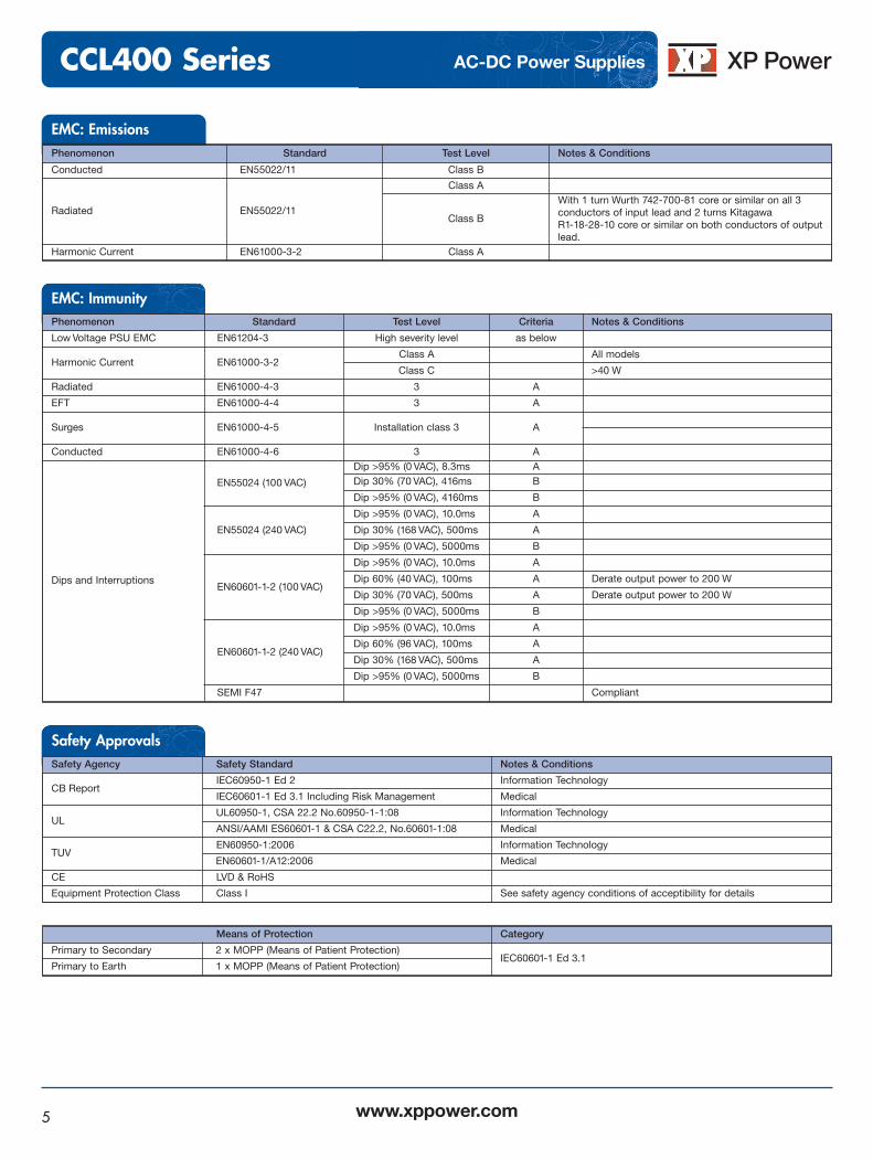
EMC: EmissionsPhenomenon Standard Test Level Notes & Conditions
Conducted EN55022/11 Class B
Radiated EN55022/11
Class A
Class B
With 1 turn Wurth 742-700-81 core or similar on all 3conductors of input lead and 2 turns Kitagawa R1-18-28-10 core or similar on both conductors of outputlead.
Harmonic Current EN61000-3-2 Class A
Safety Approvals
EMC: Immunity
Safety Agency Safety Standard Notes & Conditions
CB ReportIEC60950-1 Ed 2 Information Technology
IEC60601-1 Ed 3.1 Including Risk Management Medical
ULUL60950-1, CSA 22.2 No.60950-1-1:08 Information Technology
ANSI/AAMI ES60601-1 & CSA C22.2, No.60601-1:08 Medical
TUVEN60950-1:2006 Information Technology
EN60601-1/A12:2006 Medical
CE LVD & RoHS
Equipment Protection Class Class I See safety agency conditions of acceptibility for details
Means of Protection Category
Primary to Secondary 2 x MOPP (Means of Patient Protection) IEC60601-1 Ed 3.1
Primary to Earth 1 x MOPP (Means of Patient Protection)
Phenomenon Standard Test Level Criteria Notes & Conditions
Low Voltage PSU EMC EN61204-3 High severity level as below
Harmonic Current EN61000-3-2Class A All models
Class C >40 W
Radiated EN61000-4-3 3 A
EFT EN61000-4-4 3 A
Surges EN61000-4-5 Installation class 3 A
Conducted EN61000-4-6 3 A
Dips and Interruptions
EN55024 (100 VAC)
Dip >95% (0 VAC), 8.3ms ADip 30% (70 VAC), 416ms B
Dip >95% (0 VAC), 4160ms B
EN55024 (240 VAC)
Dip >95% (0 VAC), 10.0ms A
Dip 30% (168 VAC), 500ms A
Dip >95% (0 VAC), 5000ms B
EN60601-1-2 (100 VAC)
Dip >95% (0 VAC), 10.0ms A
Dip 60% (40 VAC), 100ms A Derate output power to 200 W
Dip 30% (70 VAC), 500ms A Derate output power to 200 W
Dip >95% (0 VAC), 5000ms B
EN60601-1-2 (240 VAC)
Dip >95% (0 VAC), 10.0ms A
Dip 60% (96 VAC), 100ms A
Dip 30% (168 VAC), 500ms A
Dip >95% (0 VAC), 5000ms B
SEMI F47 Compliant

CCL400 Series
www.xppower.com
AC-DC Power Supplies
6
Mechanical Details
A
-VE
+VE
7.12 (180.86)
1.57(39.88)
Output Voltage Control
Output TerminalM4 Screw in 2 positionsTorque to 8lbs-in (90 cNm) max.
7.0 (177.8)
2 x M3 max depth 0.16 (4.0)
6.6 (167.64)0.4 (10.16)
1.0(25.4)
3.95(100.33)
2.45(62.23)
0.75 (19.05)
0.9 (22.86) 5.2 (132.08)
4 x M3 max depth 0.12 (3.0)
Pin 1
Pin 9
Input Connector CON1
123
Pin 10
Pin 2
Detail A, Scale 1:1Signals Connector CON410 way JST B10B-PHDSS
6.6 (167.64)1.0
(25.4)
0.4 (10.16)
2 x M3 max depth 0.16 (4.0)
1. Dimensions shown in inches (mm). 2. CON4 Mating Plug: JST-PHDR-10VS
Contact: 26-22-AWG (JST-SPHD-001T-P0.5
3. For optional screw terminal input connector, add suffix ‘-S’to the model number. i.e. CCL400PS12-S (contact sales foravailability).
Notes
CON4 Signals Connector(JST B10B-PHDSS)
Pin Function1 + Standby2 + Standby3 - Standby4 - Standby5 Power Fail (Emitter)6 Power Fail (Collector)7 Inhibit (Cathode)8 Inhibit (Anode)9 - Sense10 + Sense
Output Connector
Pin Function1 +V12 + V1 RTN
CON1 Input Connector(Dinkle 166-03P3)
Pin Function1 Line2 Neutral3 Earth
CCL400
CCL400 Series
www.xppower.com
AC-DC Power Supplies
7
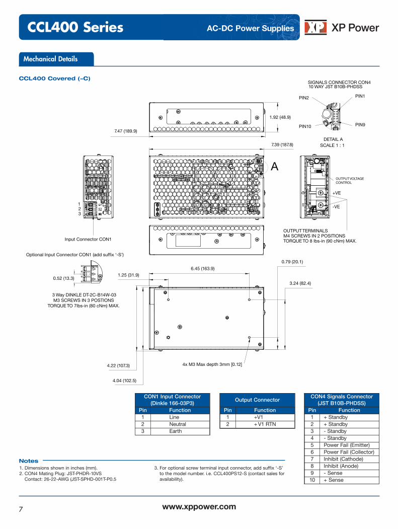
Mechanical Details
SIGNALS CONNECTOR CON410 WAY JST B10B-PHDSS
123
OUTPUT VOLTAGE CONTROL
A
OUTPUT TERMINALS M4 SCREWS IN 2 POSITIONS TORQUE TO 8 lbs-in (90 cNm) MAX.
+VE
-VE
Input Connector CON1
7.47 (189.9)
1.92 (48.9)
7.39 (187.8)
0.79 (20.1)
3.24 (82.4)
6.45 (163.9)1.25 (31.9)
4.22 (107.3)
4.04 (102.5)
4x M3 Max depth 3mm [0.12]
DETAIL ASCALE 1 : 1
PIN2 PIN1
PIN10 PIN9
0.52 (13.3)
3 Way DINKLE DT-2C-B14W-03M3 SCREWS IN 3 POSTIONS
TORQUE TO 7lbs-in (80 cNm) MAX.
Optional Input Connector CON1 (add suffix ‘-S’)
1. Dimensions shown in inches (mm). 2. CON4 Mating Plug: JST-PHDR-10VS
Contact: 26-22-AWG (JST-SPHD-001T-P0.5
3. For optional screw terminal input connector, add suffix ‘-S’to the model number. i.e. CCL400PS12-S (contact sales foravailability).
Notes
CON4 Signals Connector(JST B10B-PHDSS)
Pin Function1 + Standby2 + Standby3 - Standby4 - Standby5 Power Fail (Emitter)6 Power Fail (Collector)7 Inhibit (Cathode)8 Inhibit (Anode)9 - Sense10 + Sense
Output Connector
Pin Function1 +V12 + V1 RTN
CON1 Input Connector(Dinkle 166-03P3)
Pin Function1 Line2 Neutral3 Earth
CCL400 Covered (-C)
CCL400 Series
www.xppower.com 29 June 17
AC-DC Power Supplies
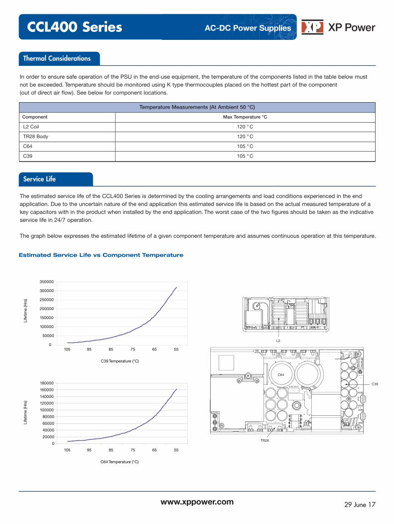
Estimated Service Life vs Component Temperature
In order to ensure safe operation of the PSU in the end-use equipment, the temperature of the components listed in the table below mustnot be exceeded. Temperature should be monitored using K type thermocouples placed on the hottest part of the component (out of direct air flow). See below for component locations.
The estimated service life of the CCL400 Series is determined by the cooling arrangements and load conditions experienced in the endapplication. Due to the uncertain nature of the end application this estimated service life is based on the actual measured temperature of akey capacitors with in the product when installed by the end application. The worst case of the two figures should be taken as the indicativeservice life in 24/7 operation.
The graph below expresses the estimated lifetime of a given component temperature and assumes continuous operation at this temperature.
Temperature Measurements (At Ambient 50 °C)
Component Max Temperature °C
L2 Coil 120 °C
TR28 Body 120 °C
C64 105 °C
C39 105 °C
Thermal Considerations
Service Life
C39
TR28
L2
C64
0
50000
100000
150000
200000
250000
300000
350000
105 95 85
C39 Temperature (°C)
C
Li
fetim
e (H
rs)
75 65 55
0
C64 Temperature (°C)
Life
time
(Hrs
)
0
20000
40000
60000
80000
100000
120000
140000
160000
180000
105 95 85 75 65 55