ccj35 layout 1 - ulisboarethink.fa.ulisboa.pt/images/repository/carbon...ccj35_layout 1 06/09/2013...
TRANSCRIPT
Sept / Oct 2013 Issue 35
Low carbon gas from mixed waste, biomass and coal: a low cost route to CCS
The industry and the CCS legal framework
IEA CCS Technology Roadmap 2013 update
EUROFER Steel Roadmap for a Low Carbon Europe 2050
ICO2N report assesses climate impact of using CO2 for EOR
CO2 storage -U.S. updateMidwest Illinois Basin -Decatur project
Battelle MichiganCO2-EOR project
Big Sky basalt lava flowCO2 storage test
CCJ35_Layout 1 06/09/2013 18:50 Page 1

Reducing the cost ofcarbon capture & storage Conference presentations
now available online
- Philippe Micone, global sales manager, Cansolv, with an update on theSaskPower Boundary Dam Project
- Harsh Pershad, energy consultant, Element Energy - latest developmentswith carbon capture
- Gernot Schneider, director marketing and sales, Carbon CaptureSequestration, Siemens - on technical challenges and cost reduction potentialfor post-combustion carbon capture
- Prateek Bumb, CTO, Carbon Clean Solutions, on developing new CO2capture solvents
- Basia Kielska, Business Development manager, ClydeUnion Pumps, ondevelopments with centrifugal pump design
- Dr Mathieu Lucquiaud, Associate Programme Director, MSc in CarbonCapture & Storage, The University of Edinburgh, on reducing the cost ofabsorber columns, DECC sponsored research
- Lord Oxburgh, honorary president of the Carbon Capture and StorageAssociation, and former chairman of Shell - where we are with carboncapture
- Panel discussion - how do we get people talking more about carbon captureand how has carbon capture developed over the past year
What is the potential for reducing the costs of CO2 capture?How do we make CCS cost competitive?
Download talks at: carboncapturejournal.com/mar2013.htm
Agenda
CCJ35_Layout 1 06/09/2013 18:50 Page 2

Contents
The Industry and the CCS Legal FrameworkThrough interviews with both ‘upstream’ and ‘downstream’ CCS industry representatives,Marko Maver from the University of Sheffield sets out to examine how the industry hascome to perceive the legal and regulatory framework for CO2 storage in the EU
IEA CCS Technology Roadmap: 2013 updateThe energy landscape has shifted between 2009 and 2013 and new insights into thechallenges and needs of CCS have been learned, says Maria van der Hoeven, ExecutiveDirector of the IEA. The new edition highlights seven key actions needed in the nextseven years to create a solid foundation for deployment of CCS starting by 2020
Eurofer presents Steel Roadmap for a Low Carbon Europe 2050The European Steel industry will be able to reduce its CO2 emissions by an estimated 15per cent in an economically viable way until 2050 compared to 2010 levels, acccordingto the “Steel Roadmap for a Low Carbon Europe 2050.”
Symposium at SaskPower Boundary DamThe inaugural Information and Planning Symposium showcased the knowledge andexperience gained from SaskPower undertaking the planning, construction andcommissioning of the world’s first and largest post-combustion commercial-scale coal-fired CCS project
ZEP report: CCS in EU energy-intensive industriesThe only technology that can provide large-scale emissions reductions in EU energy-intensive industries – such as steel, cement, refineries and chemicals – is CO2 Captureand Storage, says the report
Carbon Capture JournalUnited House, North Road, London N7 9DPwww.carboncapturejournal.comTel +44 (0)207 017 3405Fax +44 (0)207 251 9179
EditorKeith [email protected]
PublisherKarl [email protected]
Advertising and SponsorshipRichard McIntyreTel +44 (0)208 150 [email protected]
Low carbon gas from mixed waste, biomass and coal: a low cost route to CCSThis article is based on a paper by Dr. Williams at the 2012 IChemE gasification conferenceand describes an approach to integrating low carbon gas into the supply grid as a route tolow cost CCS
Novel solvent for CO2 capture receives patentAn innovative method capturing CO2 from industrial emissions is potentially cheaper andmore efficient than current methods, according to a United States patent based onresearch by Dr. Jason E. Bara, assistant professor of chemical and biological engineeringat The University of Alabama
Midwest Illinois Basin – Decatur ProjectThe Midwest Geological Sequestration Consortium’s (MGSC) Illinois Basin – DecaturProject is a collaborative effort to inject 1 million metric tons of carbon dioxide in theMount Simon sandstone formation. By Sallie Greenberg, Assistant Director of theAdvanced Energy Technology Initiative
Battelle leads CO2 storage with EOR projectAs part of a national effort to develop methods for carbon storage, Battelle is beginning alarge-scale carbon dioxide injection through the Midwest Regional Carbon SequestrationPartnership (MRCSP) program in the oil fields of Michigan’s Northern Reef Trend
BSCSP begins CO2 injection in Washington basalt formationsLed by Monata State University, the Big Sky Partnership (BSCSP) is testing CO2 storage inancient basalt lava flows, a model that could be applied in many other parts of the worldBy Lindsey Tollefson, BSCSP Project Manager
Capture and utilisation
Leaders - U.S. sequestration partnerships update
Carbon capture journal (Print) ISSN 1757-1995
Carbon capture journal (Online) ISSN 1757-2509Sept - Oct 2013 - carbon capture journal
Carbon Capture Journal is your one stopinformation source for new technicaldevelopments, opinion, regulatory andresearch activity with carbon capture,transport and storage.
Carbon Capture Journal is delivered on printand pdf version to a total of 6000 people, allof whom have requested to receive it,including employees of power companies,oil and gas companies, government,engineering companies, consultants,educators, students, and suppliers.
Subscriptions: £250 a year for 6 issues. Tosubscribe, please contact Karl Jeffery [email protected] you can subscribe online at www.d-e-j.com/store
Front cover: Schlumberger Wirelineperforming logging operations at theMidwest Geological SequestrationConsortium’s Illinois Basin – Decatur ProjectCCS1 site
4Sept / Oct 2013 Issue 35
1
17
12
Projects and policy
6
2
13
24
Transport and storageICO2N report assesses climate impact of using CO2 for enhanced oil recoveryA new report, prepared exclusively for the Integrated CO2 Network (ICO2N) by thePembina Institute, analyzes the onsite and downstream GHG emissions from using CO2for enhanced oil recovery
The status of large-scale integrated projects data courtesy of the Global CCS InstituteStatus of CCS project database 28
?
m
10
14
8
22
CCJ35_Layout 1 06/09/2013 18:50 Page 1

carbon capture journal - Sept - Oct 20132
U.S. sequestration partnerships update
The project will inject CO2 at a depth of
7,000 ft at a site owned by ADM in Decatur,
Illinois. ADM provides the carbon dioxide
as a byproduct of its production of fuel
ethanol from Illinois corn.
MGSC is one of seven regional proj-
ects funded by the US Department of Ener-
gy to test the safety and effectiveness of car-
bon capture and storage as a measure to re-
duce emission of carbon dioxide, a green-
house gas, into the atmosphere.
Injection and monitoringThe IBDP began operational injection on
November 17, 2011. In early June 2013, a
major milestone was reached as the injected
volume reached the 500,000 metric ton
mark. Injection will continue through late
2014 at which time the injection operation
will shut down when 1 million metric tons
have been injected. Environmental monitor-
ing will continue for at least three more
years, but likely longer.
To date, the injection has proceeded as
planned with the receiving reservoir, the
Mount Simon Sandstone, readily taking the
injected volume of 1,000 metric tons per
day. Capacity, injectivity, and containment
have all met pre-injection expectations and
researchers continue to focus on validating
the project’s environmental framework, un-
derstanding the carbon dioxide distribution
in the subsurface, and improvements in op-
erations and monitoring well equipment.
Pressure readings from an observation
well 1,000 feet from the injection well sug-
gest that the injected CO2 has not reached
the middle of the 1,500-foot-thick Mt. Simon
reservoir. Models that project the movement
of the CO2 plume over 100 years suggest
that the CO2 will remain below this level.
Data from a 3D vertical seismic profile ac-
quired in early April 2013 are expected to
further define the position of the plume.
Further developmentThe IBDP research effort, part of the U.S.
Department of Energy – National Technolo-
gy Laboratory’s Regional Carbon Sequestra-
tion Partnership program, is now compli-
mented by the development of additional in-
jection capacity of 2,000 metric tons per day,
under development as part of the Illinois In-
dustrial Carbon Capture and Storage proj-
ect. Both sites are at the facilities of the
Archer Daniels Midland Company in De-
catur.
The combined projects will allow eval-
uation of subsurface injected carbon dioxide
from two high-volume injection wells that
together will advance understanding of the
volumes to be dealt with at a scale much
more resembling storage from a commercial
pulverized coal power plant.
The Illinois Basin – Decatur Project has
attracted international attention as one of the
few onshore projects in the world to success-
fully reach the demonstration stage, and nu-
merous international guests have visited the
site. Countries represented include Norway,
China, Taiwan, South Korea, Spain, Japan,
Brazil, and others. Worldwide interest in the
project continues and lessons learned to date
will be detailed in an invited seminar for Eu-
ropean researchers to be held in Oslo, Nor-
way in October 2013.
Midwest Illinois Basin – Decatur ProjectThe Midwest Geological Sequestration Consortium’s (MGSC) Illinois Basin – Decatur Project (IBDP) is acollaboration of the MGSC, the Archer Daniels Midland Company (ADM), Schlumberger Carbon Services,and other subcontractors to inject 1 million metric tons of carbon dioxide.By Dr. Sallie E. Greenberg, Assistant Director of the Advanced Energy Technology Initiative
From left: Tom Stone (ADM), Rob Finley (ISGS), Sallie Greenberg (ISGS), and Scott Marsteller(Schlumberger Carbon Services) at the IBDP injection well head on startup day, November 17,2011. (Photo: Daniel Byers for the MGSC)
More [email protected]
Free London CCS eventKeeping the momentum with carbon capture and storage
London Geological Society, Nov 19, 2013
Places limited - register now to secure yours!
CCJ35_Layout 1 06/09/2013 18:51 Page 2

At SPX we understand the needs of the Carbon Capture and Storage (CCS) market and have brought together engineering expertise and
experience from our global organisation to create a specialist team focused solely on serving the CCS industry and meeting its specific
requirements. SPX is committed to delivering market leading products and services to meet the technical and commercial challenges of our
customers and helping them to meet the demands of scheduling, efficiency and reliability demanded by the CCS industry. To learn more on
how together we can create a better world for tomorrow, e-mail us at ft.enquiries.com or visit us at www.spx.com
CREATING A BETTER WORLD FOR TOMORROW
CCJ35_Layout 1 06/09/2013 18:51 Page 3

carbon capture journal - Sept - Oct 20134
U.S. sequestration partnerships update
Battelle leads CO2 storage with EOR projectin MichiganAs part of a national effort to develop methods for carbon storage, Battelle is beginning a large-scalecarbon dioxide injection through the Midwest Regional Carbon Sequestration Partnership (MRCSP)program in the oil fields of Michigan’s Northern Reef Trend.
The MRCSP is a multi-year research pro-
gram led by Battelle with a mission to iden-
tify, test and further develop the most effec-
tive approaches to carbon dioxide (CO2) uti-
lization and storage in nine states within the
Midwest and Northeast.
“This project will explore what CO2 is
doing in the deep underground, its migration
and reactions,” said Neeraj Gupta, senior re-
search leader in Battelle’s Energy & Envi-
ronment business unit. “We’re not only look-
ing at storage, but we’re also figuring out
how to utilize CO2 before it’s stored.”
Established 10 years ago by the U.S.
Department of Energy’s National Energy
Technology Laboratory (NETL), the MRC-
SP is one of seven Regional Carbon Seques-
tration Partnerships in the U.S. This project
will build on the work completed by MRC-
SP’s industry and research members during
earlier phases of the program, which includ-
ed smaller-scale testing and mapping of ge-
ologic formation across the region.
The current project in Michigan is de-
signed to inject and monitor at least 1 mil-
lion metric tons of CO2 into a series of oil
fields in different stages of their production
life-cycles. The first test in the series will in-
ject up to 500,000 metric tons of CO2 into a
depressurized, late-stage oil field that has
undergone primary production and enhanced
oil recovery for several years and is now
near the end of its productive life.
The MRCSP team instrumented the
wells and pipelines to obtain geological and
operational data that will be used to evaluate
monitoring technologies, validate reservoir
simulation models, and provide material bal-
ances on the enhanced oil recovery (EOR)
operations to determine how much CO2 is
retained in the formations.
The MRCSP team will use special tech-
niques to track the CO2 and quantify the
amount that is retained in the formation af-
ter the oil is removed, both during and after
the active injection phase (Figure 3). The
CO2 will be injected into the Niagaran pin-
nacle reef trend, an oil field comprising
highly compartmentalized ancient coral reefs
buried about 6,000 feet below the ground
surface.
As shown in Figure 3, multiple moni-
monitoring, wireline logging (e.g. pulsed
neutron capture), vertical seismic profiling,
toring technologies are being deployed to as-
sess the fate of the CO2, including pressure
Figure 1 - photograph of the CO2 injection well at the project site
Figure 2 - a review of industrial CO2 sources in the MRCSP Region belies the importance of CCS
CCJ35_Layout 1 06/09/2013 18:52 Page 4

Sept - Oct 2013 - carbon capture journal 5
U.S. sequestration partnerships update
microseismic monitoring, microgravity
monitoring, and surface deformation moni-
toring using satellites. Results of the re-
search are being used to improve under-
standing of CO2 migration and oil produc-
tion in reservoirs, interaction with surround-
ing media, geochemical and geomechanical
impacts, and storage capacity.
“The EPA is drafting CO2 regulations
based on President Barack Obama’s renewed
emphasis on climate change, which leads
Battelle into a new business area,” said Gup-
ta. “There is a lot of potential for this type
of technology in the Midwest. We’re testing,
proving and scaling it up to commercial
sizes.”
Gupta said that carbon capture, utiliza-
tion and storage represent means for a secure
energy future, and the knowledge gained
from this research will be valuable to the re-
gional economy.
“The idea of storage and injection is not
new, but this specific type of application is
unique,” said Gupta. “It’s just a matter of de-
veloping it further and ensuring its safety.”
During the last year, Battelle’s MRCSP
team has worked with Core Energy, LLC, the
owner and operator of the oil fields, to con-
duct baseline geologic characterization and
advanced monitoring and to prepare the
wells for the injection phase. These fields al-
ready are permitted for injection as part of
the routine EOR operations. In this first leg
of the field test, MRCSP expects injection
rates of approximately 1,000 metric tons of
CO2 per day.
One way to combat global climate
change is to limit greenhouse gas (such as
CO2) emissions from large-scale emitters
such as coal burning power plants. Carbon
capture, utilization and storage seeks to cap-
ture CO2 as it goes up smokestacks, pressur-
ize and dry it, then inject it deep beneath the
ground (in this case, 6,000 feet), in forma-
tions known to hold hydrocarbons for mil-
lions of years. Carbon capture, utilization
and storage is an important class of technolo-
gies and represent means for a secure energy
future. The knowledge gained from this re-
tributions by industry and research team
members. A complete list of team members
can be found on the MRCSP website.
search will be of broad value to the regional
economy and its industrial base.
The project is largely funded by DOE-
NETL under the MRCSP program, with con-
Figure 3 - monitoring options under testing at Dover 33 Field
Midwest Regional Carbon Sequestration
Partnership (MRCSP): www.mrcsp.orgCore Energy, LLC is actively in-
volved in innovative oil and gas explo-
ration and production technologies
throughout Michigan. Core was the first
company in Michigan to utilize carbon
dioxide on a commercial scale to produce
oil that would otherwise be stranded from
existing oil fields. The company is also
using modern techniques to explore for
new reserves located near existing oil
fields. Core Energy is headquartered in
Traverse City, MI. More information
about the company is available at:
www.coreenergyholdings.com
More informationContact T.R. Massey at (614) 424-5544 or
[email protected] for more
information.
At major technology centers and na-
tional laboratories around the world, Bat-
telle conducts research and development,
designs and manufactures products, and
delivers critical services for government
and commercial customers. Headquar-
tered in Columbus, Ohio since its found-
ing in 1929, Battelle serves the national
security, health and life sciences, and en-
ergy and environmental industries. For
more information, visit:
www.battelle.org
Subscribe to Carbon
Capture Journal
Six issues only £250
Sign up to our free e-mail newsletter atwww.carboncapturejournal.com
CCJ35_Layout 1 06/09/2013 18:52 Page 5

carbon capture journal - Sept - Oct 20136
U.S. sequestration partnerships update
BSCSP begins CO2 injection in Washingtonbasalt formationsLed by Montana State University, the Big Sky Partnership (BSCSP) is testing CO2 storage in ancient basaltlava flows, a model that could be applied in many other parts of the world.By Lindsey Tollefson, BSCSP Project Manager
In late July 2013, the Big Sky Carbon Se-
questration Partnership (BSCSP) kicked off
the injection phase of a field demonstration
project to determine if greenhouse gases can
be permanently stored in underground geo-
logic formations.
One of the most unique aspects of the
project is the type of geologic formation:
layers of ancient basalt flows formed by
cooling lava. “We are excited to be conduct-
ing, through our partners, the world’s first
injection of pure carbon dioxide into
basalts,” said Lee Spangler, BSCSP Direc-
tor.
On behalf of BSCSP, researchers at
Battelle are teaming with Boise, Inc. to con-
duct the test on Boise property in southwest-
ern Washington State, near Wallula. Over a
two-week period, the team injected nearly
1,000 tons of CO2 one-half mile under-
ground into porous layers of basalt. Above
and below the porous layers are imperme-
able rock layers that will trap the CO2 in
place. In addition, laboratory experiments
have shown that basalt rocks can rapidly
convert injected CO2 to solid carbonate min-
erals, permanently trapping and securing the
carbon dioxide.
“We have been conducting laboratory
tests on basalts from the region for several
years that have conclusively demonstrated
the unique geochemical nature of basalts to
quickly react with carbon dioxide and form
carbonate minerals or solid rock, the safest
and most permanent form for storage in the
subsurface,” said Battelle project manager
Pete McGrail. “However convincing the lab-
oratory data may be, proving the same
processes operate deep underground can on-
ly be done by conducting a successful field
demonstration.”
With the initial injection complete, the
research team will begin a 14 month moni-
toring period during which time they will ex-
amine fluid samples from the injection well
to look for changes in chemical composition,
as well as compare actual results to predic-
tions made with the supercomputer at the Pa-
cific Northwest National Laboratory (oper-
ated by Battelle for the Department of Ener-
gy). At the end of the monitoring period,
rock samples taken from the well are expect-
ed to exhibit the formation of carbonate min-
eralization, or limestone crystals, as a result
of the CO2 reacting with minerals in the
basalt.
If the demonstration project is success-
ful, basalt flows in many parts of the world
could serve as storage locations for CO2
emissions from a variety of industrial facili-
ties. “Basalts have the potential to store over
300 years of the carbon dioxide emissions in
the six-state Big Sky region,” Spangler said.
“Perhaps more important is their storage po-
tential in countries with rapidly increasing
energy use, specifically China and India.”
The demonstration is approximately 80
BSCSP is leading a project to inject CO2 into lava flows
CCJ35_Layout 1 06/09/2013 18:52 Page 6

Sept - Oct 2013 - carbon capture journal 7
U.S. sequestration partnerships update
percent funded through the U.S. Department
of Energy’s (DOE) National Energy Tech-
nology Laboratory. To date, $12 million has
been committed to the pilot project. Other
contributors include Schlumberger, Praxair,
Royal Dutch Shell, Boise Inc., and Portland
General Electric.
BSCSP, which is led by Montana State
University, is one of seven partnerships in-
volved in the DOE’s Regional Carbon Se-
questration Partnership Program. BSCSP is
also managing a large scale, eight-year CO2
injection project in northern Montana, which
is currently in its initial characterization and
permitting phase.
More informationFor more information about BSCSP re-
search, go to www.bigskyco2.orgLindsey Tollefson:
KNOWLEDGE & EXPERIENCE
CO2 CaptureWith a dedicated carbon capture team, in-house pilot facilities, and a full line of mass transfer and separation technology equipment for CO2 capture, Koch-Glitsch has the knowledge and experience to assist you with your carbon capture project.
Koch-Glitsch has designed equipment for 88 CO2 capture columns ranging from 50 mm to greater than 15 m in amines, chilled ammonia and mineralization services.
YOU CAN RELY ON US.™YOU CAN RELY ON US.™
“K” KOCH-GLITSCH is a trademark of Koch-Glitsch, LP and is registered in the U.S. and various other countries. YOU CAN RELY ON US is a trademark of Koch-Glitsch, LP.
United States (316) 828-5110 | Canada (905) 852-3381 | Europe: +39-035-2273411 | Asia: +65-6831-6500 www.koch-glitsch.com
1913-2013: Celebrating a century of innovation in mass transfer technology.
CCJ35_Layout 1 06/09/2013 18:52 Page 7

carbon capture journal - Sept - Oct 20138
Projects and Policy
Across the ‘CCS network’, from academic and
research institutions, to the industry and poli-
cy and decision-makers, the progress made
over the last decade or so, in terms of making
CCS a reality, should not be underestimated.
Even in getting the general public on board,
progress has been made, though admittedly
rather slow, or perhaps better said, too slow.
Any progress has to a large extent been due to
the extensive collaborative efforts within this
network.
The idea for CCS was born in the R&D
laboratories of the oil & gas industry in the
mid-1990s, but it can be said that today, in
2013, it has finally become of ‘legal’ age. Be-
coming of legal age, however, does not pre-
suppose any claims about maturity.
How long that will take depends on a
number of factors, including public accept-
ance of the technology, secured financing for
demonstration projects, as well as the indus-
try’s acceptance of the legal and regulatory
framework. In terms of the latter, it is particu-
larly important for the industry to view these
frameworks as sufficiently loose enough to al-
low them to operate without any obstructions,
yet stringent enough to provide legal certainty
in an unlikely case things go wrong.
By conducting a number of interviews
with both ‘upstream’ and ‘downstream’ CCS
industry representatives, this paper set out to
examine how the industry has thus far come
to perceive the legal and regulatory framework
for CO2 storage in the EU and whether, or
what barriers there remain in this respect.
Main issues within the legal frameworkfor CCS in the EUAs the name suggests, the (2009/31/EC) di-
rective on the geological storage of CO2 (here-
inafter the CCS Directive) is aimed primarily
at regulating the storage of the CO2, albeit
some provisions concerning capture and trans-
port as well, in order to facilitate integration
of all phases of the CCS chain.
The enabling legal framework for carbon
capture and storage in the EU has come to be
recognized as one of the most extensive pieces
of such legislation in the world, covering
everything from site exploration, selection,
permitting, monitoring, reporting, corrective
measures in case of leakage, liabilities, finan-
cial provisions, transfer of responsibility, and
Respondents also mentioned that, under
the current policy and regulatory framework,
it is for them still unclear as to how long-term
financial liability is to be handled and man-
aged. Pursuant to the current financial provi-
sions (Art. 19 and Art. 20) storage site opera-
tors are required to prove their financial com-
petence, and make a financial contribution to
the competent authority (CA) for the monitor-
ing and possible remediation purposes, fol-
lowing site closure, and until the transfer of
responsibility to the state.
However, even then, the full extent of li-
abilities is not transferred, as the Directive
makes specific references to situations where
costs incurred by respective competent author-
ities (CAs) can be recovered from the opera-
tor (Art. 18(7) - i.e. willful deceit, negligence,
provision of deficient data).
As Art. 20(1) of the CCS Directive
states, it is up to the Member States to decide
the arrangements based on which financial
contribution is made available ot the CA.
Whether financial liability is to be handled via
a type of a ‘club-fund’, whereby operators pay
into a common fund, or whether insurance
companies will be providing specific CCS
types of insurances, as one respondent men-
tioned, the fact that there is a lack of any spe-
cific set up in the CCS Directive, or subse-
quent legislation/regulation, was identified by
respondents as a significant barrier. A report
by the UK’s DECC in its April 2012 CCS
Roadmap identified this very area, the liabili-
ty arrangements, to come under scrutiny in
2015 when the CCS Directive is set to be re-
viewed.
Last, but not least, in relations to any civ-
il liabilities for harm to human health, and pri-
vate property rights issues in case of property
damage, resulting from CO2 leakage, there did
not seem to be any concern amongst the re-
spondents, and if not identified on their own,
when asked, majority stated that they believed
such issues were sufficiently covered under
the existing UK regulations, and did not pose
as a major barrier.
Third-party access Under the CCS Directive (Art. 21), it is up to
the Member States to determine the detailed
modalities for access to transportation net-
works and CO2 storage sites (Art. 21(1)),
third party access to the transport and storage
networks.
Nevertheless, while the CCS Directive is
undoubtedly a comprehensive piece of legis-
lation, which has served as a model for other
countries wishing to develop legal frameworks
for CCS within their territories, the industry
representatives in Europe continue to express
concern over a number of concepts serving as
potential legal and regulatory barriers to the
further development of CCS in Europe. Of
these, the most pressing issues for the indus-
try that have been identified remain the long-
term (financial) liability, and third-party ac-
cess, which however, remain primarily con-
centrated in the ‘downstream’ (i.e. oil & gas)
CCS industry.
For the ‘upstream’ industries (i.e. power
generation, petrochemicals, cement), the main
issues mentioned focused mainly on the capi-
tal expenditures and the lack of strong financ-
ing mechanisms. Furthermore, a number of re-
spondents also specifically mentioned the
favouritism showed by the UK competition to-
wards post-combustion technology.
Given that the focus of the EU legal and
regulatory framework in the EU is on the stor-
age component, the majority of the chosen re-
spondents were primarily from the ‘down-
stream’ end of the CCS chain, thus the focus
here is on the above mentioned issues; long-
term liability and third-party access.
Long-term financial liability ‘Downstream’ CO2 storage operators essen-
tially have fairly little incentive to store the
CO2, given that the majority of the reward is
to be, technically at least, kept by the capture
operators. This incentive is provided by the
EU ETS. However, the current EUA price
(4.43EUR/tonne as of August 23, 2013) is at
one of its lowest points in history, thus, as one
respondent pointed out, “there is no denying
the fact that this will not provide sufficient in-
centive at all, in particular for the storage op-
erators solely dealing with storage, not includ-
ing any EOR into their revenue stream”.
So, when an operator dealing with pure
storage is required to set aside a part of their
revenue stream, for post-closure monitoring
and possible remediation efforts, with a low
and volatile EUA price, there is indeed very
little incentive to move forward.
The Industry and the CCS Legal FrameworkThrough interviews with both ‘upstream’ and ‘downstream’ CCS industry representatives, Marko Maversets out to examine how the industry has come to perceive the legal and regulatory framework for CO2storage in the EU and assesses any barriers that remain.By Marko Maver, University of Sheffield, UK
CCJ35_Layout 1 06/09/2013 18:52 Page 8

Sept - Oct 2013 - carbon capture journal 9
Projects and Policy
North American bottom-up CCS approachdelivers more than EU’s top-down, says IEAThe National Energy Technology Laboratory’s (NETL) Carbon Storage R&D meeting took place inPittsburgh in the United States, reports Bellona. John Gale, general manager of the International EnergyAgency (IEA) Greenhouse Gas R&D Programme, addressed the conference and said the United States’bottom-up approach to CCS project development had produced much better results than theEuropean top-down approach. www.bellona.org
which needs to be provided in a transparent
and non-discriminatory manner (Art. 21(2)).
While the decision to provide, or deny, access
to the transportation network or a storage site
ultimately still resides in the hands of the op-
erator, their decision needs to be justified. For
example, if denying access, the operator can
do so on the ground of a lack of capacity, or
incompatibility of technical specifications
which cannot be economically and ecological-
ly overcome. Given the potential transbound-
ary nature of storage sites and transportation
networks, pursuant to Art. 22 of the CCS Di-
rective, Member States are also obligated to
implement dispute settlement arrangements,
as well as are required to act jointly (Art. 24).
The second major issue identified by the
respondents was the issue of third party ac-
cess. Depending on the carbon price, access to
transportation networks and CO2 storage op-
erations could become a condition for com-
petitive operation in the EU energy market, as
Scott Brockett form the EU Commission
points out (2009). In its writing of the CCS
Directive, the Commission decided to be
somewhat vague, or better said, adopted a
lighter regulatory approach.
This was done on purpose given the rel-
ative early stages of CCS development, how-
party, who is responsible for that? In other
words, where does the responsibility and ac-
countability come from for the molecules
coming from various pipelines and/or par-
ties?”
ConclusionThere is no doubt that Europe has one of the
best sets of regulations out there, that are, as
seemed to have been a common agreement
amongst the respondents, reasonably straight
forward and reasonably well understood.
In terms of procedural requirements at
least, the UK deployment of the CCS Direc-
tive was also considered pretty well under-
stood. As mentioned, the main legal and regu-
latory issues within the industry seem to re-
volve around the long-term financial liability
and third-party access. Nevertheless, it should
be pointed out that for the most part the re-
spondents seem to be rather positive in regards
to these two issues being addressed in the fu-
ture, in particular in light of the 2015 review
of the CCS Directive.
ever, it said that third-party access will be kept
under the scope in case of any anti-competi-
tive practices emerging. When asked about
their views on the issue, majority of respon-
dents pointed out that while it is true that to-
date the issue of third party access has not
come up yet, however, as a representative
from BP pointed out, “once CCS takes off, this
might prove to be the largest source of com-
mercial uncertainty for the industry…the
Commission will really need to address this,
once the Directive comes under review in
2015”.
In the UK, third-party access is ad-
dressed by the CO2 Storage (Access to Infra-
structure) Regulations 2011, which were seen
by the respondents for the most part as “good”,
“fair”, and “straight forward and reasonably
well understood”. However a number of is-
sues seemed to remain for the industry in rela-
tion to third-party access.
One respondent suggested that there re-
mains the lack of any specific provisions in re-
lation to the revenue stream: “If you build up
the infrastructure and another power station
wants to tap in your infrastructure, how do you
decide the revenue or the tariff?”. Yet another
was concerned that “if something happens to
your storage facility, after you take on the third
More [email protected]
The more phased approach to developing CO2
Capture and Storage (CCS) projects over the
last decade in the US seems to have boosted
both R&D and public acceptance more than
in Europe. Europe has instead been charac-
terised by politicians trying to drive industry,
but without taking the necessary steps. GHG
News reported Gale to have said that “the Eu-
ropeans took a top-down approach of setting a
high-level policy goal of 20 demonstration
projects by 2020, but they didn’t do much of
the underpinning R&D.
Whereas the U.S. took a bit of the alter-
native approach, which saw the phased build-
up of projects and bringing people on board.”
Gale further noted: “You bring the learnings
from smaller projects and use them in the
demonstration project. That ensures that you
have a scientific basis to explain to the politi-
cians that the process is safe and secure, that
spiral of delays and accumulating costs, with
the initial estimated cost having more than
quadrupled so far.
SaskPower and the role of smaller-scale
projects to instill confidence and public ac-
ceptance must not be underplayed. “In my
mind, pilots are key to the global implementa-
tion of CCS at the moment. They’re building
our knowledge base and they’re key to build-
ing public confidence in our technology to get
us to larger-scale implementation,” Gale said.
As public opposition to CCS in Europe
remains high, projects such as Mongstad do
not improve the case to convince both the pub-
lic and investors of CCS projects’ viability.
Countries like Germany and the Netherlands
have especially high opposition levels, with
the latter having taken the step to ban onshore
CO2 storage, limiting projects to offshore
sites.
you’re not taking a risk with investments.”
One such key development in Canada,
where CCS project conditions are more simi-
lar to those in the US than EU, is SaskPow-
er’s Boundary Dam is the province of
Saskatchewan. Boundary Dam was developed
as a commercial project to be used for testing
only once up and running. This has now been
achieved within budget and only at a fraction
of the total cost befalling the tax payer. Bound-
ary Dam also has a diverse set of revenue
streams, with electricity, CO2 for Enhanced
Oil Recovery (EOR), H2SO4 and fly-ash by-
products.
In stark contrast to BoundaryDam is the
Mongstad test facility on the Norwegian West
coast. The technology centre, is the world’s
largest and arguably most technologically ad-
vanced, but its future utility beyond testing is
highly uncertain. And it is currently stuck in a
CCJ35_Layout 1 06/09/2013 18:52 Page 9

carbon capture journal - Sept - Oct 201310
Projects and Policy
Between 2009 when the first IEA Carbon
Capture and Storage (CCS) roadmap was
published, and 2013, the need for CCS has
not diminished: the urgency of its deploy-
ment has in fact grown, says the IEA in its
updated Roadmap.
There have been many developments
and significant gains in CCS technology and
the enabling policy frameworks. However,
given today’s level of fossil fuel utilisation,
and that a carbon price as a key driver for
CCS remains missing, the deployment of
CCS is running far below the trajectory re-
quired to limit long-term global average tem-
perature increases to 2 °C.
Purpose for the roadmapThe goal of the updated CCS roadmap is to
describe and analyse actions needed to ac-
celerate CCS deployment to levels that
would allow it to fulfil its CO2 emissions re-
duction potential. The IEA is revising the
2009 roadmap to reflect developments in
CCS that have occurred over the last four
years and to develop a plan of action that ful-
ly reflects the current context.
Key findingsCarbon capture and storage (CCS) will be
a critical component in a portfolio of low-
carbon energy technologies if govern-
ments undertake ambitious measures to
combat climate change.
Given current trends of increasing
global energy sector carbon dioxide (CO2)
emissions and the dominant role that fossil
fuels continue to play in primary energy con-
sumption, the urgency of CCS deployment
is only increasing. Under the International
Energy Agency (IEA) Energy Technology
Perspectives 2012 (ETP 2012) 2 °C Scenario
(2DS)1, CCS contributes one-sixth of CO2
emission reductions required in 2050, and
14% of the cumulative emissions reductions
between 2015 and 2050 compared to a busi-
ness-as-usual approach, which would corre-
spond to a 6 °C rise in average global tem-
perature.
The individual component technologies
required for capture, transport and stor-
age are generally well understood and, in
some cases, technologically mature.
For example, capture of CO2 from nat-
ural gas sweetening and hydrogen produc-
tion is technically mature and commercially
practiced, as is transport of CO2 by
pipelines. While safe and effective storage
of CO2 has been demonstrated, there are still
many lessons to gain from large-scale proj-
ects, and more effort is needed to identify vi-
able storage sites. However, the largest chal-
lenge for CCS deployment is the integration
of component technologies into large-scale
demonstration projects. Lack of understand-
ing and acceptance of the technology by the
public, as well as some energy and climate
stakeholders, also contributes to delays and
difficulties in deployment.
Governments and industry must ensure
that the incentive and regulatory frame-
works are in place to deliver upwards of
30 operating CCS projects by 2020 across
a range of processes and industrial sec-
tors.
This would be equivalent to all projects
in advanced stages of planning today reach-
ing operation by that time. Co-operation
among governments should be encouraged
to ensure that the global distribution of proj-
ects covers the full spectrum of CCS appli-
cations, and mechanisms should be estab-
lished to facilitate knowledge sharing from
early CCS projects.
CCS is not only about electricity genera-
tion. Almost half (45%) of the CO2 cap-
tured between 2015 and 2050 in the 2DS
is from industrial applications.
In this scenario, between 25% and 40%
of the global production of steel, cement and
chemicals must be equipped with CCS by
2050. Achieving this level of deployment in
industrial applications will require capture
technologies to be demonstrated by 2020,
particularly for iron and steelmaking, as well
as cement production.
Given their rapid growth in energy de-
mand, the largest deployment of CCS will
need to occur in non-Organisation for
Economic Co-operation and Development
(OECD) countries.
By 2050, non-OECD countries will
need to account for 70% of the total cumula-
tive mass of captured CO2, with China alone
accounting for one-third of the global total
of captured CO2 between 2015 and 2050.
OECD governments and multilateral devel-
opment banks must work together with non-
OECD countries to ensure that support
IEA CCS Technology Roadmap: 2013 updateThe energy landscape has shifted between 2009 and 2013 and new insights into the challenges andneeds of CCS have been learned, says Maria van der Hoeven, Executive Director of the IEA. The newedition highlights seven key actions needed in the next seven years to create a solid foundation fordeployment of CCS starting by 2020.
Seven key actions for the next seven yearsThe next seven years are critical to the accelerated development of CCS, which is necessary
to achieve low-carbon stabilisation goals (i.e. limiting long-term global average temperature
increase to 2 °C). The seven key actions below are necessary up to 2020 to lay the foundation
for scaled-up CCS deployment. They require serious dedication by governments and indus-
try, but are realistic and cover all three elements of the CCS process.
1. Introduce financial support mechanisms for demonstration and early deployment of
CCS to drive private financing of projects.
2. Implement policies that encourage storage exploration, characterisation and develop-
ment for CCS projects.
3. Develop national laws and regulations as well as provisions for multilateral finance
that effectively require new-build, base-load, fossil-fuel power generation capacity to be CCS-
ready.
4. Prove capture systems at pilot scale in industrial applications where CO2 capture has
not yet been demonstrated.
5. Significantly increase efforts to improve understanding among the public and stake-
holders of CCS technology and the importance of its deployment.
6. Reduce the cost of electricity from power plants equipped with capture through con-
tinued technology development and use of highest possible efficiency power generation cy-
cles.
7. Encourage efficient development of CO2 transport infrastructure by anticipating loca-
tions of future demand centres and future volumes of CO2.
1. #The 2DS describes how technologies across all
energy sectors may be transformed by 2050 for an
80% chance of limiting average global temperature
increase to 2 °C.
CCJ35_Layout 1 06/09/2013 18:52 Page 10

Sept - Oct 2013 - carbon capture journal 11
Projects and Policy
to encourage development of CO2 storage
and transport infrastructure.
development of strong business models for
CCS, which are so far lacking. Urgent ac-
tion is required from industry and govern-
ments to develop such models and to imple-
ment incentive frameworks that can help
them to drive cost-effective CCS deploy-
ment. Moreover, planning and actions which
take future demand into account are needed
mechanisms are established to drive deploy-
ment of CCS in non-OECD countries in the
coming decades.
This decade is critical for moving deploy-
ment of CCS beyond the demonstration
phase in accordance with the 2DS.
Mobilising the large amounts of finan-
cial resources necessary will depend on the
More informationDownload the complete Roadmap at:
www.iea.org
Area Progress as of 2013
The 2009 CCS roadmap highlighted the need to develop 100 CCS
projects between 2010 and 2020, storing around 300 MtCO2/yr.
Four large-scale CCS projects have carried out sufficient monitoring to
provide confidence that injected CO2 will be permanently retained.
Collectively, these projects have stored approximately 50 megatonnes of
carbon dioxide (MtCO2). Nine further projects under construction
together have the potential to capture and store 13 MtCO2/yr. All nine
projects should be operational by 2016. Numerous other large projects
are in operation and demonstrate one or more technologies in the CCS
chain.
The 2009 CCS roadmap suggested that OECD countries will need to
invest USD 3.5 billion per year (b/yr) to USD 4 b/yr, and non-OECD
countries USD 1.5 b/yr to USD 2 b/yr between 2010 and 2020 to
meet the roadmap deployment milestones.
Actual cumulative spending between 2007 and 2012 on projects that
demonstrate CCS reached almost USD 10.2 billion. Hence, while
spending has been significant, the level targeted by the 2009 roadmap
has largely not been met. Government grants contributed USD 2.4
billion of this total. Almost all of this funding is from governments in the
United States and Canada (federal and state or provincial). In addition,
over the same period a USD 12.1 billion of public funds was made
available to CCS.
The 2009 CCS roadmap highlighted the importance of CCS in
industrial sectors and called for dedicated actions in specific
industrial sectors.
Despite significant activity in some industrial areas, notably gas
processing, CCS action in a number of key industrial sectors is almost
totally absent (IEA/ UNIDO, 2011). There is a dearth of projects in the
iron and steel, cement, oil refining, biofuels and pulp and paper sectors.
Only two possible demonstration projects at iron and steel plants, and
one at coal-to-chemicals/liquids plants, are at advanced stages of
planning (Global CCS Institute, 2013).
The 2009 CCS roadmap presented a vision for CO2 transport and
storage that started with analysis of CO2 sources, sinks and storage
resources, followed by the development of best-practice guidelines
and safety regulations by 2020 and leading to a roll-out of pipeline
networks to developed storage sites.
Considerable progress has been made in understanding the size and
distribution of technically accessible storage resources, factors affecting
the cost of storage, and in the development of best-practice
recommendations and standards for geologic storage (CSA, 2012; DNV,
2009). The International Organization for Standardization (ISO) has also
started a process to develop a series of international standards for CCS.
However, much more needs to be done to develop these two elements of
the CCS chain to support the scale
Development of comprehensive CCS regulatory frameworks in all
countries by 2020 and the resolution of legal issues for trans-
boundary transfer of CO2 by 2012 were identified as key regulatory
milestones in the 2009 CCS roadmap.
Some OECD countries (e.g. in Europe; the United States; Canada;
Australia) have made significant progress in developing laws ensuring
that CO2 storage is carried out safely and effectively, and are continuing
to refine aspects of their frameworks through secondary legislation (IEA,
2012d). Other countries that plan to demonstrate CCS, such as South
Africa, are undertaking processes that will lead to comprehensive
regulations for CCS. In the area of international law, the 2007
amendment to the Convention for the Protection of the Marine
Environment of the North-East Atlantic (OSPAR convention) entered
into force in 2011; however, the 2009 amendment to the London
Protocol has not yet been ratified by a sufficient number of signatory
governments. As an important political development, CCS has also been
accepted as a CDM activity under the UNFCCC with related modalities
and procedures.
CCJ35_Layout 1 06/09/2013 18:52 Page 11

carbon capture journal - Sept - Oct 201312
Projects and Policy
technology and full deployment of Carbon
Capture and Storage (CCS) in Europe. How-
ever, this technology has yet to be proven as
technically feasible at industrial scale.
Moreover, to date the economic viabili-
ty and the general applicability of CCS in Eu-
rope appear questionable. Public resistance to
CCS in a growing number of Member States
as well as the lack of a business case for such
a technology make it doubtful that the tech-
nology will be applied throughout Europe in
the foreseeable future.
Gordon Moffat, Director General of Eu-
rofer: “The steel industry cannot stay in Eu-
rope if the Commission’s targets are imposed
on the sector without further adaptation. In
fact, we will not even be able to meet the 2030
intermediate milestone of the EU Emissions
Trading Scheme of 43 to 48 per cent reduc-
tion as suggested in the Commission’s
Roadmap. The technologies to do so are not
there at present and if they will ever emerge,
it will certainly not be on time for the Com-
mission’s schedule. It must be acknowledged
that sectors like steel cannot follow the decar-
bonisation path at the same pace than others.”
Potential breakthrough technologies Deep CO2 cuts as postulated in the Commis-
sion’s Roadmap might be achieved only with
radically new and yet unproven breakthrough
technologies. The ULCOS research pro-
gramme (Ultra-Low CO2 Steelmaking),
which started in 2004 already, has identified
four potential breakthrough technologies.
Two of these technologies have been tested
on a pilot plant level; none has been demon-
strated on an industrial scale yet.
Gordon Moffat: “The EU Emissions
Trading Scheme, although some people re-
gard it as a means to incentivise investments
in low-carbon technology, will not help here.
For making the ULCOS technologies an in-
dustrial reality it would take much more than
just a high price on emissions allowances.
The massive investments required for
demonstration and deployment of these po-
tential technologies clearly exceed our indus-
try’s investment capabilities. Therefore, fi-
nancial support is needed which is consistent
with the level of ambition of the EU’s climate
objectives. This issue should be an integral
part of the 2030 Climate and Energy pack-
age.”
Life-cycle thinking Following a holistic approach, the Eurofer
Roadmap not only looks into possible CO2
abatement in steel production. It also analy-
ses the CO2 mitigation potential from inno-
vative technologies in which steel cannot be
replaced by any other material. This analysis
was done by Boston Consulting Group, too.
According to case studies on eight se-
Eurofer presents Steel Roadmap for a LowCarbon Europe 2050 The European Steel industry will be able to reduce its CO2 emissions by an estimated 15 per cent in aneconomically viable way until 2050 compared to 2010 levels, acccording to the “Steel Roadmap for aLow Carbon Europe 2050.”
The document, produced by the European
Steel Association in response to the European
Commission’s “Roadmap for moving to a
low-carbon economy in 2050”, pools the re-
sults of recent studies on technical and eco-
nomical potentials for CO2 reduction in steel
making. It also looks into possible break-
through technologies and points out policies
which would enable the sector to maintain
production in Europe.
The Commission’s Roadmap postulates
a reduction of 80 to 95 per cent by 2050 com-
pared to 1990 for European industry. The Eu-
rofer Roadmap builds upon the results of a
study conducted by the Boston Consulting
Group earlier this year, which confirm that
this target is far beyond the reach of the steel
sector.
The study draws several possible scenar-
ios for CO2 abatement in steel making. In the
economic scenario, only 10 per cent emis-
sions reduction per tonne of steel are possible
between 2010 and 2030 and 15 per cent be-
tween 2010 and 2050. This would be brought
about by the use of best available technolo-
gies, process optimization and a greater use
of steel scrap.
The most promising abatement scenario,
theoretically resulting in 60 per cent emis-
sions reductions per tonne of steel between
2010 and 2050, relies on the retrofitting of ex-
isting blast furnaces with top-gas recycling
Source: BCG-VDEh, EUROFER
1.4
1.6
1990 2000 2010 2020 2030 2040 2050
1.2
1.0
0.8
0.6
0.4
0.2
0
CO
2 in
ten
sit
y (
ton
ne
CO
2 /
to
nn
e o
f s
tee
l)
EU ETS cap declining path
(according to the Commission
Low Carbon Roadmap)
1
2
3
4
5
HOW?
Economic scenarios
Uneconomic scenarios
CONDITIONS FOR SUCCESS
Overarching conditions
Uneconomic scenarios
2
WHAT?
Economic scenarios
Uneconomic scenarios
2
2
1
2
3
4
5
+
+
+
Emission reduction potentials are expressed in specific CO2 emissions relatively to 2010
CCS: Carbon Capture and Storage
BF-BOF: Blast Furnace-Basic Oxygen Furnace
BF-TGR: Blast Furnace with Top Gas Recycling technology
DRI: Direct Reduction of Iron
EAF: Electric Arc Furnace
NG: natural gas
CO2 intensity pathway scenarios for the EU steel industry up to 2050
CCJ35_Layout 1 06/09/2013 18:52 Page 12

Sept - Oct 2013 - carbon capture journal 13
Projects and Policy
lected steel applications, including weight re-
duced car parts, electric motors or efficiency-
improved power plants, the yearly savings
would amount to at least 443 million tonnes
CO2 in 2030. The prognosis is limited to 2030
because this is a timespan for which the ex-
pansion of the technologies looked into can
be forecast with sufficient probability.
The amount of 443 million tonnes has to
be compared to the emissions released in the
production of the steels applied, which
amount to only 70 million tonnes. Another
comparison: the total steel industry’s emis-
sions in 2010 were approximately 220 mil-
lion tonnes; less than half of the savings po-
tential of only the eight steel applications
looked at in the study.
This indicates that European climate tar-
gets can hardly be reached without steel. It al-
so calls for a change of perspective on the po-
litical level. Current climate policies focus on
emissions from the production phase of mate-
rials. For steel, this overlooks the material’s
substantial contribution to climate protection
when it is applied in relevant technologies. As
yet, European climate policies have no room
for this holistic approach, which would also
have to integrate the recycling properties of
materials.
Gordon Moffat: “Steel is as indispensa-
ble for European manufacturing value chains
as it is essential for technologies protecting
the climate. Unilateral climate action along
the mitigation path suggested by the Commis-
sion has potentially devastating effects on the
EU steel industry. Post-2020 policies should
therefore be built bottom-up, taking into con-
sideration technological development. They
should also include effective protection
against CO2-related costs which jeopardize
global competitiveness of the EU industry.
Only with a modern, innovative and prof-
itable industry in Europe can the EU’s targets
for a sustainable, carbon-lean and competi-
tive economy be met.”
More informationwww.eurofer.be
Source: BCG/VDEh
Case study
Efficient fossil-fuel PPs
Offshore wind power
Efficient transformers
Efficient e-motors
Weight reduction - cars
Weight reduction - trucks
Combined heat/power
Other renewables1
Net CO2 reduction potential2
per anno from 2030 onwardsRatio between CO2 reduction / emission
Emissions from steel production3
ENERGY INDUSTRY
1 ~ 155:1
~ 443 ~ 70 ~ 6:1
~ 23:1
~ 148:1
~ 17:1
~ 2:1
~ 4:1
< 1
~ 9 :1
2
5
7
8
4
6
3
TRAFFIC
HOUSEHOLD / INDUSTRY
0 050
Mt CO2 / yr.
103.0 0.7
3.0
165.9
69.7
22.2 0.16
1.2
3.2
42.1
14.0
5.3
19.6
6.9
6.3
49.6
5100 10200 45
Mt CO2 / yr.
Source: Steel Institute VDEh; Project team analysisNote: PP = power plant1 Bioenergy. 2 Net reduction refers to reduction attributable to steel. 3 Refers to the emissions related to the amount of steel needed for the specific application.
Case studies for EU27 result in CO2 savings
Symposium at SaskPower Boundary Dam The inaugural Information and Planning Symposium showcased the knowledge and experience gainedfrom SaskPower undertaking the planning, construction and commissioning of the world’s first andlargest post-combustion commercial-scale coal-fired CCS project. www.saskpowerccsconsortium.com
The three day program included facilitated
technical discussions and a guided tour of the
Boundary Dam Power Station and Carbon
Capture Facility. Over 100 participants and
speakers from 12 different countries attended
the Symposium.
Doug Daverne, Director, Carbon Cap-
ture and Storage Initiatives, SaskPower, pro-
vided the first technical presentation with a
focus on the preparatory components that led
to beginning construction on the Boundary
Dam Unit #3 rebuild and capture facility
project. He spoke about the financial invest-
ment and time commitment that SaskPower
made prior to deciding to proceed with the
Unit #3 demonstration project. In his presen-
tation he spoke about:
• Evaluating the feasibility of coal
generated electricity integrated with CCS
technology on a new unit versus an
existing unit;
• Finding out true market costs versus
relying on estimates;
• Identifying capture system and
refurbishment costs; and
• Comparing costs of coal-fired electricity
to natural gas.
Throughout the rest of the day, Sympo-
sium participants gained insight on the vari-
ous activities and groups who have con-
tributed to the project. Topics discussed were:
• Integrated Process Design by SaskPower
• Contract Strategy and Procurement by
SaskPower
• Engineering for a CCS Project by Stantec
• Providing the Capture Process by Cansolv
Technologies Inc.
• From Engineering, to Procurement, to
Construction by SNC-Lavalin Inc.
Day two featured a tour of the Boundary
Dam Power Station and Carbon Capture Fa-
cility in Estevan, a visit to the Aquistore stor-
age site just two kilometers away from
Boundary Dam, and a drive by the Cenovus
oil fields near Weyburn where the captured
CO2 will be used for enhanced oil recovery.
More presentations on day three includ-
ed SaskPower project leads providing talks
on the power station re-build, operating a
capture facility, and future CCS opportuni-
ties at SaskPower. The morning session con-
cluded with the introduction to the SaskPow-
er Global CCS Consortium initiative.
Mike Monea, SaskPower President of
Carbon Capture and Storage Initiatives, pre-
sented the available membership opportuni-
ties and the benefits of joining the Consor-
tium. A strong focus of the presentation was
how SaskPower’s Boundary Dam CCS expe-
riences are transferable to other CCS related
projects, and how the knowledge gained from
those experiences will have significant im-
pact on planning for future CCS initiatives.
He addressed how Boundary Dam is the
first generation of CCS development at
SaskPower and that there is already planning
in place for the next generation of CCS in
Saskatchewan. Preliminary assessments for
integrating CCS with Boundary Dam Units
#4 and 5 (generation 2, SaskPower CCS Ini-
tiatives) have already begun.
CCJ35_Layout 1 06/09/2013 18:52 Page 13
carbon capture journal - Sept - Oct 201314
Projects and Policy
programme for Recovery, or the use of struc-
tural funds”.
Finally, ZEP welcomes signals from the
European Parliament’s Environment Com-
mittee (ENVI) in its latest (19th June) vote
on the so-called ‘back-loading’ of emission
unit allowances (EUAs) in the EU ETS.
The ENVI call for two-thirds of the
EUAs that the Commission has proposed to
remove from the carbon market (and freeze
for later auctioning) to be “made available
to set up a fund to support the development
of innovative low-carbon technologies,
demonstration projects and measures intend-
ed to reduce the costs and carbon emissions
of energy-intensive industries”. This aligns
with Director-General Delbeke’s and the
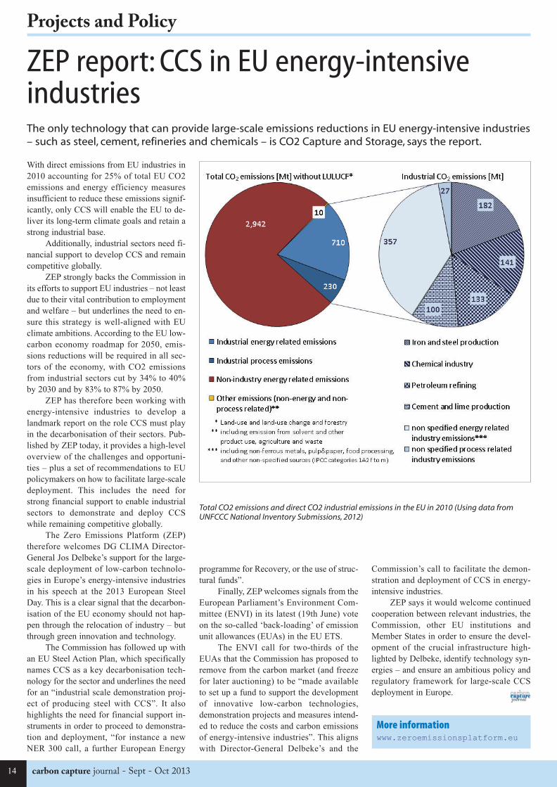
With direct emissions from EU industries in
2010 accounting for 25% of total EU CO2
emissions and energy efficiency measures
insufficient to reduce these emissions signif-
icantly, only CCS will enable the EU to de-
liver its long-term climate goals and retain a
strong industrial base.
Additionally, industrial sectors need fi-
nancial support to develop CCS and remain
competitive globally.
ZEP strongly backs the Commission in
its efforts to support EU industries – not least
due to their vital contribution to employment
and welfare – but underlines the need to en-
sure this strategy is well-aligned with EU
climate ambitions. According to the EU low-
carbon economy roadmap for 2050, emis-
sions reductions will be required in all sec-
tors of the economy, with CO2 emissions
from industrial sectors cut by 34% to 40%
by 2030 and by 83% to 87% by 2050.
ZEP has therefore been working with
energy-intensive industries to develop a
landmark report on the role CCS must play
in the decarbonisation of their sectors. Pub-
lished by ZEP today, it provides a high-level
overview of the challenges and opportuni-
ties – plus a set of recommendations to EU
policymakers on how to facilitate large-scale
deployment. This includes the need for
strong financial support to enable industrial
sectors to demonstrate and deploy CCS
while remaining competitive globally.
The Zero Emissions Platform (ZEP)
therefore welcomes DG CLIMA Director-
General Jos Delbeke’s support for the large-
scale deployment of low-carbon technolo-
gies in Europe’s energy-intensive industries
in his speech at the 2013 European Steel
Day. This is a clear signal that the decarbon-
isation of the EU economy should not hap-
pen through the relocation of industry – but
through green innovation and technology.
The Commission has followed up with
an EU Steel Action Plan, which specifically
names CCS as a key decarbonisation tech-
nology for the sector and underlines the need
for an “industrial scale demonstration proj-
ect of producing steel with CCS”. It also
highlights the need for financial support in-
struments in order to proceed to demonstra-
tion and deployment, “for instance a new
NER 300 call, a further European Energy
Commission’s call to facilitate the demon-
stration and deployment of CCS in energy-
intensive industries.
ZEP says it would welcome continued
cooperation between relevant industries, the
Commission, other EU institutions and
Member States in order to ensure the devel-
opment of the crucial infrastructure high-
lighted by Delbeke, identify technology syn-
ergies – and ensure an ambitious policy and
regulatory framework for large-scale CCS
deployment in Europe.
ZEP report: CCS in EU energy-intensiveindustriesThe only technology that can provide large-scale emissions reductions in EU energy-intensive industries– such as steel, cement, refineries and chemicals – is CO2 Capture and Storage, says the report.
More informationwww.zeroemissionsplatform.eu
Total CO2 emissions and direct CO2 industrial emissions in the EU in 2010 (Using data fromUNFCCC National Inventory Submissions, 2012)
CCJ35_Layout 1 06/09/2013 18:52 Page 14

Sept - Oct 2013 - carbon capture journal 15
Projects and Policy
Bellona promotes revision of EU ETS www.bellona.orgIn its response to the European Commis-
sion’s Green Paper on a 2030 Framework
for Climate and Energy Policies, Bellona
has put forward a suggestion to struc-
turally and institutionally revise the EU
ETS.
The proposed changes intend to stabi-
lize the price of carbon and thereby create
an opportunity for the mechanism to become
the major driver towards long term low car-
bon investment, says Sirin Engen, Bellona
The European Commission’s 2030
Green Paper, released on 27 March, invited
stakeholders to take part in a consultative
process towards the Union’s climate and en-
ergy policies after 2020. The new policy
framework towards 2030 is regarded as an
important tool for the EU to reach its target
of reducing greenhouse gas emissions by 80-
95% by 2050 compared to 1990 levels, as
stipulated in the Energy Roadmap 2050. Bel-
lona provided the Commission with its re-
sponse to the consultation on 2 July.
Bellona emphasized the importance of
ensuring that the various measures for cli-
mate change mitigation in the EU should be
equally supportive. Under the current frame-
work, there is an unfortunate consequence of
taking large-scale measures on e.g. energy
efficiency or renewable energy deployment,
in that those measures reduce the demand for
emission allowances (EUAs) and thus re-
duces the carbon price, in turn undermining
the long-term business case for such invest-
ments.
The unexpectedly deep and long reces-
sion, combined with the interaction with oth-
er carbon reduction policies, has led to a sig-
nificant oversupply of allowances in the
market. Climate efforts in the EU are strug-
gling with the current price of carbon; it was
forecasted that ETS Emission Unit Al-
lowances (EUAs) would be traded at around
or above €30 in 2013. At the time of writing,
EUAs are trading at around €4.30/tCO2.
Structural reform of the EU ETS Under
the current system, the EU ETS is in prac-
tice failing to provide a realistic price on car-
bon and does therefore not stimulate the up-
front investment and innovation necessary
to meet the ambitious emissions reductions
proposed in the Commission’s 2050 low-car-
bon roadmap.
Because the perception of future scarci-
ty and price stability are important factors
for a well-functioning carbon market, Bel-
lona supports a structural reform of the ETS
that will allow it to respond to situations of
over-supply, as in the current market context.
Bellona therefore suggested a reform of the
ETS which will establish governance
arrangements for optional adjustments to the
supply of allowances.
This price-based mechanism ought to
be regulated by an independent bank; a Eu-
ropean Central Bank of Carbon.
European Central Bank of Carbon To-
day, adjusting the supply of quotas implies a
lengthy political process. “Because address-
ing climate change is a matter of outmost im-
portance, we believe that the carbon market
should be entrusted to an independent regu-
lator to make the necessary decisions to en-
able the market to function”, says Director
of Bellona Europa, Jonas Helseth.
“The establishment of a European Cen-
tral Bank of Carbon will ensure that the ETS
reacts swiftly and with flexibility to unpre-
dictable changes in carbon demand and
thereby safeguard the orderly functioning of
the market”, Helseth continues. “This bank
must be given a mandate with a view to en-
sure full decarbonisation at the lowest eco-
nomical impact in the coming decades to-
ward 2050. In this way, measures to promote
green technologies will not undermine the
carbon market, but strengthen it”, he con-
cludes.
Technology-specific targets Lessons
learnt from the 2020 strategy has shown that
clear and legally binding targets for tech-
nologies can be very valuable, if they are de-
signed to interact properly with other meas-
ures. “Bellona therefore supports new and
ambitious legally binding targets for 2030
for renewables as well as for energy efficien-
cy and CO2 Capture and Storage (CCS)”,
says Jonas Helseth; “showing such political
will can create early markets for emerging
technologies and generate necessary invest-
ments to bring down costs that in the future
will make Member State funding mecha-
nisms obsolete as the carbon price reaches
adequate levels”.
CCS A separate communication on
CCS was released alongside the Green Pa-
per for climate and energy. Bellona has writ-
ten responses to both, yet made it clear that
the issue of CCS in Europe should not be
treated in parallel to other policies but rather
as an integral part of the strategy towards
2030.
“At the EU level, Bellona recommends
that the Union sets a similar milestone for
CCS as it has previously done for renewable
energy in order to ensure the political com-
mitment and necessary funding to drive CCS
forward in Europe”, says Helseth.
Way forward The various responses to
the Green Paper from stakeholders all across
Europe will now feed into the Commission’s
on-going preparations for more concrete pro-
posals for the EU’s 2030 framework for cli-
mate and energy policies, which are expect-
ed to be tabled by the end of 2013. The
Member States have indicated that they in-
tend to have a political debate with a view
to provide some initial conclusions on the
Commission’s proposals at the European
Council in March 2014.
BECCS could lead to climate changereversal iopscience.iop.orgBioenergy with carbon capture and stor-
age (BECCS) can reverse the global
warming trend and push temperatures
back below the global target of 2°C above
pre-industrial levels.
This is according to a new study in the
Institute of Physics Publishing’s journal En-
vironmental Research Letters, which shows
that ambitious temperature targets can be ex-
ceeded then reclaimed by implementing
BECCS around mid-century.
The researchers, from Chalmers Uni-
versity of Technology in Sweden, show that
if BECCS is implemented on a large-scale
along with other renewable energy sources,
temperature increases can be as low as 1.5°C
by 2150.
Co-author of the study, Professor Chris-
tian Azar, said: “What we demonstrate in our
paper is that even if we fail to keep tempera-
ture increases below 2°C, then we can re-
verse the warming trend and push tempera-
tures back below the 2°C target by 2150.
“To do so requires both large-scale use
of BECCS and reducing other emissions to
near-zero levels using other renewables –
mainly solar energy – or nuclear power.”
BECCS is a greenhouse gas mitigation
technology based on bioenergy that produces
fuel for power plants or transportation while
simultaneously removing carbon dioxide
from the atmosphere. Trees and crops give
off carbon dioxide when they are burnt as fu-
el, but also act as a carbon sink as they grow
beforehand, absorbing carbon dioxide from
the atmosphere. These two processes cancel
each other out, resulting in net zero emis-
sions of carbon dioxide.
When combined with carbon capture
and storage – techniques that aim to pull car-
bon dioxide out of the flue gases from pow-
er plants and redirect it into geological stor-
age locations – the overall carbon dioxide
emissions are negative. If applied on a glob-
al scale, this could help to reverse global
warming.
In their study, the researchers devel-
Policy, projects and regulation news
CCJ35_Layout 1 06/09/2013 18:52 Page 15

carbon capture journal - Sept - Oct 201316
Projects and Policy
oped an integrated global energy system and
climate model that enabled them to assess
the most cost-effective way forward for a
given energy demand scenario and tempera-
ture target.
They find that stringent temperature
targets can be met at significantly lower
costs if BECCS is implemented 30 to 50
years from now, although this may cause a
temporary overshoot of the 2°C target.
“The most policy relevant implication
of our study is that even if current political
gridlock causes global warming in excess of
2°C, we can reverse the temperature trend
and reach targets later. This means that 2°C
targets or even more ambitious targets can
remain on the table in international climate
negotiations,” Azar continues.
However, the authors caution against
interpreting their study as an argument for
delaying emission reductions in the near-
term.
Azar says: “BECCS can only reverse
global warming if we have net negative
emissions from the entire global energy sys-
tem. This means that all other CO2 emis-
sions need to be reduced to nearly zero.
“Also, temperatures can only be re-
duced by about 0.6°C per century, which is
too slow to act as an 'emergency brake' if cli-
mate damages turn out to be too high. The
more we reduce emissions now, the more
ambitious targets we can achieve in the long
term – even with BECCS.”
UK research on public attitudes toenergy change www.ukerc.ac.ukThe findings of the study, funded by the
UK Energy Research Centre (UKERC)
and carried out by a team from the Uni-
versities of Cardiff and Nottingham, re-
veal that people in Britain are fully sup-
portive of the idea of energy system
change.
People were unfamiliar with carbon
capture and storage (42% of people had nev-
er heard of it) and when given further infor-
mation many expressed concern, viewing it
as a “non transition? – a continuation of un-
sustainable practices associated with fossil
fuels.
The research as a whole highlights key
factors that influence public assessment of
proposed changes. From examining these
factors, the research shows that the public
favours changes that are: energy efficient
rather than wasteful; protect the environment
and nature; are reliable, accessible and safe;
allow consumers a certain amount of auton-
omy and power; are socially just and fair;
improve on what has gone before; score well
in terms of quality and performance; and, fit
with a long-term, sustainable trajectory,
rather than being just a short-term fix.
The report proposes that energy poli-
cies not taking account of these factors in
combination are unlikely to secure public
support.
Professor Nick Pidgeon, who led the re-
search team, said: “Our participants saw the
bigger picture of energy system transforma-
tion, and they were overwhelmingly com-
mitted to moving away from fossil fuels to-
wards renewable forms of energy produc-
tion, and to lowering energy demand”.
The study synthesis report “Transform-
ing the UK energy system – public values,
attitudes and acceptability? brings together
the findings from two in-depth phases of re-
search carried out over thirty months; a se-
ries of six in-depth deliberative workshops
with members of the public held across Eng-
land, Scotland and Wales; and a nationally
representative survey of 2,441 members of
the public.
Some of the major findings include:
* In the national survey 74% of partici-
pants were very or fairly concerned about
climate change, while 82% were worried
about the UK becoming too dependent upon
energy from other countries.
* 79% wanted to see a reduction in the
use of fossil fuels over the next few
decades.
* 81% expressed a desire to reduce
their energy use; and support for solar
(85%) and wind energy (75%) remained
very strong.
* The public is undecided on the role
of nuclear power in the future energy mix.
However, over half (54%) still said they
would oppose the building of a new nuclear
power station in their area.
* Awareness of new low-carbon tech-
nologies for the home, such as “heat
pumps?, was low. The percentage of people
willing to use electric heating rose from
42% to 61% if it was posed as matching the
performance of current systems, and to 85%
if it was also presented as cheaper. A ma-
jority (53%) were willing to use electric ve-
hicles, rising to 75% if they performed as
well as conventional models.
* There were mixed views about smart
metering and so-called “demand side man-
agement? – where use of new information
technology helps to promote energy effi-
ciency and reduction measures. Here, no-
tions about the home being a private space,
free from outside control, were important.
People were also more open to the idea of
appliances being turned off automatically af-
ter a period on standby, for example, than
they were about having their showering
times curtailed or their fridges and freezers
controlled remotely.
* Whilst most people were willing to
share their electricity data, around a fifth
(22%) were not. Interestingly, people were
more willing to share data about their elec-
tricity use with energy companies than with
the Government, who they perceived to be
motivated by short-term motives related to
the electoral cycle rather than a genuine de-
sire for change.
* Neither energy companies nor Gov-
ernment were trusted, and the research in-
dicates that this issue must be addressed for
successful energy system change.
Professor Pidgeon comments: “Our re-
search has shown clearly that people are
more likely to accept changes that show
signs of commitment to their underlying val-
ues, such as energy system components that
are clean, efficient, fair and safe. The public
is also keen for policy makers to clarify how
current changes to the energy system fit with
longer-term plans, and to develop an intelli-
gible and coherent strategy for this”.
Subscribe to Carbon
Capture Journal
Six issues only £[email protected]
Sign up to our free e-mail newsletter atwww.carboncapturejournal.com
CCJ35_Layout 1 06/09/2013 18:52 Page 16

17
Capture and Utilisation
Low carbon gas from mixed waste, biomassand coal: a low cost route to CCSThis article is based on a paper by Dr. Williams at the 2012 IChemE gasification conference anddescribes an approach to integrating low carbon gas into the supply grid as a route to low cost CCSBy Tony Day consultant cost benefit analyst; Dr. Williams of GL Noble Denton Ltd, and Chris Hodrien of Timmins CCS Ltd.
British Gas (BG) developed high efficiency
coal to Synthetic Natural Gas (SNG) tech-
nology between 1955 and 1992. Costly
British coal made SNG uneconomic com-
pared with cheap North Sea gas. Replacing
coal by low cost waste makes SNG econom-
ically competitive. 60 bar negative emissions
LCG produced for 40 to 45 p/therm, less
than the cost of Natural Gas, will enable gas
users, and existing CCGT’s, to be decar-
bonised at zero cost.
SNG making is inherently carbon cap-
ture ready. CO2 separation and compression
is standard gas industry practise. High pres-
sure LCG made by co-gasifying partly bio-
genic mixed waste, biomass and coal, using
the integrated ex-BG SNG and high CO2
partial pressure Timmins CCS processes,
produces supercritical CO2 by-product for
40p/tonne. Per unit energy output, 3 to 4
times less CO2 is produced by LCG than
CCS on fossil power generation. Supercriti-
cal CO2 produced in smaller quantities, at
lower cost, is more useful for enhanced oil,
gas and Coal Bed Methane recovery, ‘dry’
fracking and CCU than large quantities of
expensive CO2 from fossil power genera-
tion.
The three main gaseous energy vectors
are: Synthesis Gas (Syngas), Hydrogen and
methane. Of these, methane is the most use-
ful, providing the backbone
of the UK energy system.
Delivering decarbonisation
policy targets at reasonable
cost requires the substantial
decarbonising of gas sup-
plies. This possibility is ex-
plored in this article.
Off-setting the carbonatom in the methanemoleculeLow Carbon Gas (LCG) is
made by combining the
methanation of 50+% bio-
genic
mixed
part
bio-
genic and part fossil
fuels, with CCS. Se-
questering sustainably
sourced biogenic CO2
removes anthro-
pogenic CO2 from the
Earth’s atmosphere.
The negative
emissions from se-
questering biogenic
carbon are used to off-
set fossil carbon emis-
sions. Biogenic carbon
emissions and se-
questered fossil carbon
are accounted as emis-
sions neutral. The waste CO2 by-product of
methanation used for CCS is typically over
50% of the total Carbon throughput. Com-
bining 50+% biogenic fuel and 50+% CCS
produces negative net emissions of anthro-
pogenic CO2.
Gt. Plains Synfuel plant produces com-
mercially viable SNG from lignite. Inherent-
ly carbon capture ready methanation pro-
duces waste CO2 by-product for commercial
EOR. Replacing part of the lignite fuel at Gt.
Plains with low cost mixed wastes and bio-
mass would economically decarbonise the
product SNG to produce LCG.
Injecting low cost high pressure LCG
into the gas grid decarbonises existingMethane: the ideal gaseous energy vector. How do you get rid of thecarbon atom in the methane molecule?
Low carbon gas
Sept - Oct 2013 - carbon capture journal
CCJ35_Layout 1 06/09/2013 18:52 Page 17

18 carbon capture journal - Sept - Oct 2013
Capture and Utilisation
CCGT’s at zero operational cost, or loss of
load factor. CCGT’s can be geographically
distributed, with LCG plants grouped near
CCS ‘hubs’. Carbon capture ready unabated
LCG plants can easily be abated when a su-
percritical CO2 ‘hub’ or pipeline becomes
available. LCG can support low cost Power
to Gas and intermittent renewable energy
storage. Low cost supercritical CO2 can
support ‘dry fracking’, enhanced oil or shale
gas recovery and CCS in depleted shale gas
wells providing an onshore gas industry
method of reducing the cost of decarbonis-
ing energy supplies, and the cost of CCS. In-
tegrated methane synthesis with CCS is the
key ‘hub’ technology to deliver low carbon
gas and power.
Reducing the cost of synthetic gasThe cost of synthetic methane is dependent
on:
• Efficient process design.
• Fuel cost.
• Cost of capital.
• Economies of scale.
Process efficiencyBG’s cost studies indicate that for a given
process, and cost of fuel and finance, the out-
put cost of SNG was dependent on plant size
and process pressure. BGL gasification at 65
bar pressure was demonstrated at Westfield
in the 1980’s. BG estimated that gasifying
coal at 80 bar would produce 60 bar SNG at
76% efficiency unabated. The BGL gasifier
produces high methane content Syngas. In-
creasing gasification pressure, and replacing
coal by the plastic in waste, increases
methane yield and reduces the work to con-
vert Syngas to methane
A recent 4 year proof of concept study,
using commercially confidential ex-BG cost
and engineering data, indicates that integrat-
is developing rapidly.
The Lurgi dry ash gasifier was devel-
oped during the 1930’s. The first pilot of its
derivative the slagging Lurgi gasifier was
built in 1943 to gasify Italian lignite. In 1947
HM Ministry of Fuel and Power reported
that the economic case for the slagging gasi-
fication of low grade fuel lay in the fuel cost
being low enough to cover the cost of oxy-
gen. In 1955 the Ministry purchased the
rights to the slagging Lurgi gasifier, now
called the British Gas Lurgi or BGL gasifier.
This uses less steam and oxygen than
the dry ash version. The future of gasifica-
tion in Europe lies in gasifying low grade
secondary fuels. The diversion of large quan-
tities of waste from landfill has turned resid-
ual waste into a useful low cost fuel. The
‘spread’ between the unit cost of low cost
mixed wastes, biomass and coal, and the unit
cost of fossil Natural Gas makes SNG pro-
duction in EU and UK economically viable.
Reducing the cost of sustainable gasThe avoided cost of 2015 UK Landfill Tax
at £-8/GJ offsets the cost of coal and biomass
at around £2.25 to £4.0/GJ producing a near
zero cost 50+% biogenic fuel mix. The
‘spread’ between waste at £-8/GJ and Natu-
ral Gas at around £6.25/GJ makes convert-
ing waste to gas financially attractive. Using
some coal in the fuel mix to provide the en-
ergy to drive slagging gasification is far
more economic than using electricity to
drive plasma gasification.
The projected 40 to 45 p/therm
(£15/MWh) unit cost of 60 bar storable LCG
at from high CO2 partial pressure LCG mak-
ing with CCS is around 1/6th the projected
£100/MWh unit cost of CCS on low CO2
ing proven high efficiency BG methanation
technology operating at 70 bar with waste
based fuels, and Timmins CCS, produces 60
bar pipeline ready negative emissions LCG,
and dry 99.6% pure 150 bar supercritical
CO2, at a net efficiency of 76.75%. This
must be one of the few cases where the use
of low grade secondary fuels, and adding
CCS, increases the efficiency of the under-
lying unabated technology.
The economics of methane synthesisSNG production is established technology,
its economic viability depending on the price
‘spread’ between the fuel and Natural Gas.
Due to the large ‘spread’ between low cost
stranded West China coal and expensive East
coast LNG imports, inter-connected by low
cost gas pipelines, SNG production in China
Injecting low cost high pressure LCG into the gas grid
British Gas: world’s highest cold gas efficiency solid multi-fuel gasifier
Steam
4.3
Heat in slag
0.6
Heat losses
3.7
Recoverable
heat
5.5
Byproduct
recycle
13.2
Gaseous
sulphur
compunds
1.0
CCJ35_Layout 1 06/09/2013 18:53 Page 18

19
Capture and Utilisation
The BGL is counter-current gasifier.
Hot Syngas flows upwards from the gasifi-
cation zone at the bottom of the gasifier
causing the fuel being fed by gravity from
the top of the gasifier to be dried, pre-heat-
ed, devolatilised and pyrolised prior to gasi-
fication. The Syngas is cooled from around
2000 to 5000C. Internal heat exchange re-
duces the need for external Syngas cooling
and heat exchange, and increases process ef-
ficiency.
HICOM combined catalytic shift and
methanation combines two exothermic reac-
tions. This reduces the requirement for ex-
ternal heat exchange, and maximises
exothermic energy recovery to high temper-
ature and pressure steam used for power gen-
eration and process utilities. The shift reac-
tion absorbs water. The methanation reaction
produces water. Internal water exchange oc-
curs between the shift and methanation reac-
tions. This reduces steam injection and
downstream water vapour removal.
catalysts are used at Great Plains and the re-
cently completed Phase 1 SNG plant at
Datang.
High efficiency thermo-chemical massand energy transferBoth the BGL gasifier and HICOM com-
bined shift and methanation use internal
mass and energy transfer to maximise
process energy efficiency. Carbon is oxi-
dised to provide the energy to drive the gasi-
fication and methanation reactions. During
gasification and methanation, oxygen and
steam are injected into the process gas
stream.
The hydrogen to oxygen molecular
bond in the steam is broken, and the hydro-
gen re-bonded to carbon, producing
methane. CO2 is separated to leave the
methane product gas. Hydrogen and oxygen
are added to the process gas stream, and CO2
is removed. In essence, carbon to hydrogen
mass and energy exchange occurs.
partial pressure fossil fuel power generation.
The 40p/tonne unit cost of supercritical CO2
(sCO2) from an LCG plant with Timmins
CCS is around 2 orders of magnitude lower
than for fossil fuel power generation. The
cost per unit energy of sCO2 transport and
storage from an LCG plant is around ¼ to
1/3rd the cost per unit energy of sCO2 trans-
port and storage from CCS on fossil fuel
power generation.
Co-gasifying approximately 50%
mixed secondary fuels: residual hazardous
and non-hazardous residential, commercial
and industrial wastes; Refuse and Tyre De-
rived Fuel; petcoke; sewage and industrial
sludges; 30% contaminated and woody bio-
mass, and 20% coal or briquetted lignite re-
duces input fuel costs to near zero, and con-
tains nearly 55% biogenic carbon, deliver-
ing LCG and CCS at lower cost than any
other fuel/technology mix.
British Gas synthetic gasdevelopmentsWhen the UK gas grid was converted from
Towns Gas to Natural Gas, it was known that
the different properties of the two gases
would make re-conversion to Towns Gas im-
practical. It was unclear whether UK pos-
sessed sufficient Natural Gas to supply its
needs, and how long it would last. Support-
ed by HM Government, BG embarked on a
strategic long-term programme to develop
SNG against a future shortage of Natural
Gas.
BG “High Speed Gas” naptha to SNG
conversion was commercialised in USA.
Pulverised coal hydrogenation to SNG was
demonstrated at test rig scale. Commercial
scale high efficiency BGL slagging gasifica-
tion and HICOM combined catalytic shift
and methanation of lump or briquetted coal
to SNG technology was developed between
1955 and 1992 The SNG development plant
at Westfield was mothballed on completed
of the R and D programme.
Co-gasifying waste, biomass and coal
using the BGL gasifier was demonstrated
commercially at SVZ Schwarze Pumpe be-
tween the late 1980’s and 2007. Gt. Plains
has been converting lignite to SNG since
1984 using Lurgi dry ash gasifiers, with CCS
for EOR since 1999. Westfield, Gt. Plains
and SVZ were always inherently carbon cap-
ture ready.
Different elements of the LCG process
chain were developed at the plants, but the
whole chain was not demonstrated at a sin-
gle plant. Except for this accident of history,
large scale low cost LCG might have been
commercialised 30 years ago. BGL gasifiers
are being built in China to use low grade
stranded North China coal assets. HICOM
British Gas slagging gasifier based on proven Lurgi dry ash gasifier: high efficiency due to lowsteam and oxygen use
British Gas HICOM high efficiency combined shift and catalytic methanation process
Sept - Oct 2013 - carbon capture journal
CCJ35_Layout 1 06/09/2013 18:53 Page 19

20 carbon capture journal - Sept - Oct 2013
Capture and Utilisation
The importance of CO2 partial pressureIPPC, IEA, UK CCSA and Schlumberger
state that CO2 partial pressure (CO2 concen-
tration x pressure) is the ‘key’ determinant
of CO2 capture and compression cost, which
is 80% of the cost of CCS. CO2 solubility in
a carrier liquid is a function of gas pressure.
The volume flow rate of gases, and vessels,
pipe and pump size, is a function of gas pres-
sure. CO2 concentration determines the
amount of gas to be processed to obtain a
given amount of CO2.
For the same energy input, the CO2
partial pressure in an SNG plant with Tim-
mins CCS is 250 times greater, and the gas
volume flow rate 400 times less, than in a
fossil fuel power plant with post-capture
CCS. This massive engineering and cost
benefit is due not to any ‘magic’, but to ba-
sic process physics and chemistry.
Timmins CCSCyril Timmins led the BG SNG commercial-
isation programme. His co-patentee, Keith
Tart was co-patentee for HICOM. The Tim-
mins CCS recycle loop is a generic process
for reducing the cost of separating CO2 from
mixed gas streams at over 10 bar gas pres-
sure. The efficiency penalty of CO2 separa-
tion and compression is reduced by running
the whole plant at high pressure, with no
pressure let-down.
The cost of cryogenic separation is re-
duced by separating half the CO2 at each
pass. The part CO2 content gas mix is recy-
cled back into the process using the incom-
ing process gas as ‘stripping gas’. The CO2
recycle loop is the basis for the patent, and
is applicable to any process separating CO2
from high pressure mixed gases.
The Timmins CCS process is an elegant
‘fit’ with high pressure HICOM combined
shift and methanation. In the integrated
process, the high CO2 partial pressure assists
in inhibiting the harmful Boudouard reaction
(2CO = C + CO2). The recirculated CO2 as-
sists gas cooling during exothermic metha-
nation. Cryogenic separation of part of the
CO2 stream reduces the work done by the
Selexol plant. The volume flow rate of the
process gases is 400 times less, and the CO2
partial pressure is 240 times greater, than
post combustion CCS on fossil fuel power
generation.
In the unabated LCG with Timmins
CCS case, dry 99.6% pure liquid CO2 is pro-
duced at 60 bar. In the abated case, the ener-
gy penalty to pump cool liquid CO2 to 150
bar supercritical state is only 0.06%. This
leads to the Marginal Abatement Cost of
Carbon capture and compression of
£0.4/tonne, excluding transport and storage
costs.
The transport and storage cost of CO2
per unit energy is 25 to 33% that for CCS on
fossil fuel power generation.
Comparative costs of powergeneration with CCSCCS Association’s recently reported on re-
Comparative CCS CO2 partial pressures
TechnologyLow carbon gas
(LCG)
Post capture
coalOxyfuel coal
Pre captureIGCC
Gas flow 2.5 m3/sec 1000 m3/sec 200 m3/sec 10 m3/sec
CO2 partial
pressure
32.4 bar 0.13 bar 0.65 bar 13.5 bar
Comparative gas volumes and CO2 partial pressures
Power to gas and intermittent renewable energy storage with CCS
CCJ35_Layout 1 06/09/2013 18:53 Page 20

21Sept - Oct 2013 - carbon capture journal
Capture and Utilisation
ducing the whole system cost of CCS on
power generation. Using the CCSA’s pub-
lished data, and LCG production cost analy-
ses, the ‘whole system’ cost (including trans-
port and storage) of power from LCG is
around 1/3rd the cost of CCS on fossil fuel
power generation. The whole system cost per
tonne of CO2 from LCG is between 5% and
10% of CCS on fossil fuel power generation.
Spin-off uses for low cost LCG andsupercritical CO2 production (P2G,EOR/EGR, CCS/U)Gasification technology is highly flexible.
Clean Syngas supports numerous down-
stream uses for Syngas. Low cost LCG, low
cost supercritical CO2 and ‘green’ Hydrogen
can support a variety of clean energy tech-
nologies.
Power to gas and intermittentrenewable energy storageLCG production uses both the hydrogen and
oxygen produced by P2G plants, and the ex-
isting gas grid for economical bulk renew-
able energy storage and transmission. Inject-
ing hydrogen into HICOM increases
methane production and reduces CO2 pro-
duction.
Less steam is required for the shift re-
action; less excess steam has to be removed
after methanation, and exothermic heat out-
put increases. Oxygen from electrolysis re-
duces the load on the air separation unit.
LCG plant efficiency is increased for the
same fuel input and plant CAPEX. The en-
hanced Return on Capital Employed for the
LCG plant can be used to offset the low
ROCE for the P2G plant.
‘Dry’ fracking, enhanced gas recovery(EGR) and enhanced coal bed methanerecovery (ECBR)Low cost supercritical CO2 can be used for:
drilling; enhanced shale ‘dry’ fracking and
proppant; EGR by methane desorption,
reservoir re-pressurisation and ‘sweep’ gas,
and CCS in depleted conventional and un-
conventional oil and gas wells. Most Natu-
ral Gas reservoirs contain some CO2, which
must be removed in order to meet gas quali-
ty standards. Timmins CCS can be used for
gas removing CO2 returned from conven-
tional gas, EGR and ECBR.
Making CCS into an economicpropositionMaking economic use of supercritical CO2
for EOR and EGR depends critically on
matching supercritical CO2 supply and de-
mand to raise the revenue to pay for CCS in-
frastructure. A typical large UKCS oil field
uses around 2 to 3 mtpa of supercritical CO2
Carbon capture and utilisation (CCS/U)Low cost LCG derived from waste and in-
dustrial sources, low cost high purity CO2
produced by Timmins CCS, and ‘green’ hy-
drogen can support a wide variety of chemi-
cal and biological synthesis routes to pro-
duce a variety of low carbon products, foods
and energy vectors. Some of the more prom-
ising of these are shown above. In this con-
cept, Syngas, hydrogen and LCG production
are integrated around the ‘core’ methane
synthesis and CCS.
for a period of around 5 years, reducing by
around 50% after 5 years.
A 1GWe fossil fuel power station pro-
duces around 6 mtpa of CO2, but this may
fluctuate dramatically depending on the bal-
ance of electricity supply and demand in the
grid. A 1 GWSNG LCG plant produces
around 1.75 mtpa of CO2, and will operate
largely at constant throughput as the gas grid
operates as an effectively infinite capacity
energy store.
This will enable supercritical CO2 sup-
ply and demand by the UKCS oil and gas in-
dustry to be balanced against supercritical
CO2 production from LCG more easily than
for fossil fuel power generation.
SNG hub integrates energy grids and storage, CCS/U, biofuels, steel and industry
‘Dry’ fracking and enhanced gas recovery with CCS
More informationTony Day
CCJ35_Layout 1 06/09/2013 18:53 Page 21

22 carbon capture journal - Sept - Oct 2013
Capture and Utilisation
Capture and utilisation news
Novel solvent for CO2 capture receivespatentuanews.ua.eduAn innovative method capturing CO2
from industrial emissions is potentially
cheaper and more efficient than current
methods, according to a United States
patent based on research by Dr. Jason E.
Bara, assistant professor of chemical and
biological engineering at The University
of Alabama.
Many commercially-available CO2
capture methods use a liquid solution of wa-
ter and amine to absorb the gas. The system
patented by Bara would replace much of the
water in the aqueous amine solutions with a
promising class of molecules known as imi-
dazoles, organic solvents with a low vapor
pressure, or boiling point.
The patent, granted earlier in August to
UA, claims the chemical make-up of the im-
idazole-containing systems for use in captur-
ing CO2 and other gases from natural gas
and post-combustion emissions such as those
from coal-fired power plants.
“The advantages of imidazoles in car-
bon capture are that they are a class of sol-
vents with tunable chemical and physical
properties,” Bara said. “This gives us a lot
of flexibility in designing a solvent system
that can meet process demands.”
One of the most common commercial-
ly used and most studied solvents is mo-
noethanolamine, or MEA. The use of MEA
to scrub flue gas is energy intensive since re-
cycling the solution requires boiling it to
desorb, or rid, the CO2before recycle of the
MEA solution back into contact with the flue
gas. The cost of the energy needed to use
MEA in power plants, for example, would
likely be passed onto consumers, Bara said.
Bara's work shows that swapping most
of the water in the process with imidazoles
saves energy since the solvent can be regen-
erated without the energy penalties associat-
ed with boiling large amounts of water.
Bara's research shows the solvent system can
capture the same or more CO2than MEA.
The cost of capturing carbon is one rea-
son the energy industry has been reluctant to
embrace carbon capture on a large scale.
“That's why it is important to look at sol-
vents and materials that are tweaks to what
are already established if we hope to do very
large scale up over the next decade,” Bara
said.
“What's really nice about this solvent
system is that we're not starting from
scratch,” he said. “Many imidazole cores are
already commercially available, and through
some very simple reactions, we can synthe-
size the molecules we want in the lab. This
should bode well in terms of solvent cost if
we were to scale them up.”
This technology has been licensed to
the clean tech company ION Engineering in
Boulder, Colo., with the hope of further de-
veloping this technology for carbon dioxide
capture. Bara helped found ION Engineer-
ing, and continues as a science adviser with
the company.
Bara's research is funded by the U.S.
Department of Energy, the National Science
Foundation and the American Chemical Soci-
ety Petroleum Research Fund.First CO2 cap-
tured in ADEME, Alstom and EDF project
The first tonne of CO2 has beencaptured at the EDF power plant in LeHavre, France. www.alstom.comThe project was awarded funding by the
French Environment and Energy Man-
agement Agency (ADEME) in 2010.
This pilot is installed in unit 4 at the
EDF thermal power station in Le Havre. The
technology, provided by Alstom in partner-
ship with The Dow Chemical Co. and cho-
sen by EDF, consists in cleaning the flue gas
with UCARSOLTM FGC-3000 amine sol-
vent from Dow, which is the base component
of the reagent used to separate CO2 from the
flue gas. For this pilot unit, Alstom and Dow
have deployed an advanced configuration for
the process, specifically developed to min-
imise energy consumption.
The objective, using this research pro-
totype, is to capture about 1 tonne of CO2
per hour. The CO2 will be released into the
atmosphere, the aim of the project being to
test the CO2 capture process itself and not
the storage. Following technical testing,
EDF will analyse the cost implications of the
process.
A dozen engineers from the Research
and Development teams at EDF and Alstom
are driving the tests. The intent of these tests
is to confirm the predicted quantity of ener-
gy and amine solvent required to operate the
unit, so as to assess whether the process is
worthwhile from a cost and an environmen-
tal standpoint. They will also look at how the
unit performs in an industrial setting, as well
as how flexible it is to use within a fully op-
erating power plant. Such tests represent a
crucial step in developing efficient industrial
solutions for capturing CO2.
Akermin pilot completes 1600 hours ofCO2 capture www.akermin.comThe pilot plant using biocatalytic technol-
ogy completed 1,600 hours of operation
capturing CO2 from the flue gas exhaust
of a coal-fired power plant.
Since Akermin initiated operation of
the pilot plant with its Biocatalyst Delivery
System in May 2013, the unit has consistent-
ly captured over 80% CO2 from the flue gas
exhaust. During this period, it has operated
with no biocatalyst replenishment while
demonstrating significant rate enhancement,
Research led by Dr. Jason E. Bara shows a more efficient and cheaper method for capturingcarbon dioxide
CCJ35_Layout 1 06/09/2013 18:53 Page 22
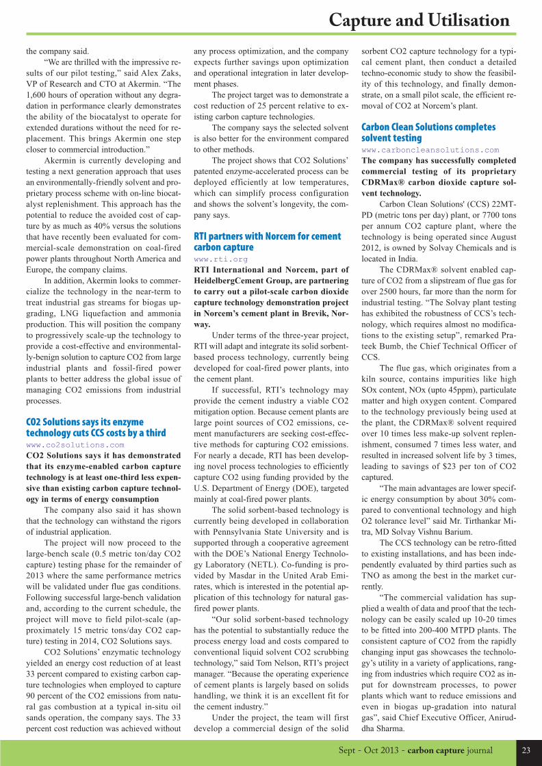
23Sept - Oct 2013 - carbon capture journal
Capture and Utilisation
the company said.
“We are thrilled with the impressive re-
sults of our pilot testing,” said Alex Zaks,
VP of Research and CTO at Akermin. “The
1,600 hours of operation without any degra-
dation in performance clearly demonstrates
the ability of the biocatalyst to operate for
extended durations without the need for re-
placement. This brings Akermin one step
closer to commercial introduction.”
Akermin is currently developing and
testing a next generation approach that uses
an environmentally-friendly solvent and pro-
prietary process scheme with on-line biocat-
alyst replenishment. This approach has the
potential to reduce the avoided cost of cap-
ture by as much as 40% versus the solutions
that have recently been evaluated for com-
mercial-scale demonstration on coal-fired
power plants throughout North America and
Europe, the company claims.
In addition, Akermin looks to commer-
cialize the technology in the near-term to
treat industrial gas streams for biogas up-
grading, LNG liquefaction and ammonia
production. This will position the company
to progressively scale-up the technology to
provide a cost-effective and environmental-
ly-benign solution to capture CO2 from large
industrial plants and fossil-fired power
plants to better address the global issue of
managing CO2 emissions from industrial
processes.
CO2 Solutions says its enzymetechnology cuts CCS costs by a thirdwww.co2solutions.comCO2 Solutions says it has demonstrated
that its enzyme-enabled carbon capture
technology is at least one-third less expen-
sive than existing carbon capture technol-
ogy in terms of energy consumption
The company also said it has shown
that the technology can withstand the rigors
of industrial application.
The project will now proceed to the
large-bench scale (0.5 metric ton/day CO2
capture) testing phase for the remainder of
2013 where the same performance metrics
will be validated under flue gas conditions.
Following successful large-bench validation
and, according to the current schedule, the
project will move to field pilot-scale (ap-
proximately 15 metric tons/day CO2 cap-
ture) testing in 2014, CO2 Solutions says.
CO2 Solutions’ enzymatic technology
yielded an energy cost reduction of at least
33 percent compared to existing carbon cap-
ture technologies when employed to capture
90 percent of the CO2 emissions from natu-
ral gas combustion at a typical in-situ oil
sands operation, the company says. The 33
percent cost reduction was achieved without
sorbent CO2 capture technology for a typi-
cal cement plant, then conduct a detailed
techno-economic study to show the feasibil-
ity of this technology, and finally demon-
strate, on a small pilot scale, the efficient re-
moval of CO2 at Norcem’s plant.
Carbon Clean Solutions completessolvent testing www.carboncleansolutions.comThe company has successfully completed
commercial testing of its proprietary
CDRMax® carbon dioxide capture sol-
vent technology.
Carbon Clean Solutions' (CCS) 22MT-
PD (metric tons per day) plant, or 7700 tons
per annum CO2 capture plant, where the
technology is being operated since August
2012, is owned by Solvay Chemicals and is
located in India.
The CDRMax® solvent enabled cap-
ture of CO2 from a slipstream of flue gas for
over 2500 hours, far more than the norm for
industrial testing. “The Solvay plant testing
has exhibited the robustness of CCS’s tech-
nology, which requires almost no modifica-
tions to the existing setup”, remarked Pra-
teek Bumb, the Chief Technical Officer of
CCS.
The flue gas, which originates from a
kiln source, contains impurities like high
SOx content, NOx (upto 45ppm), particulate
matter and high oxygen content. Compared
to the technology previously being used at
the plant, the CDRMax® solvent required
over 10 times less make-up solvent replen-
ishment, consumed 7 times less water, and
resulted in increased solvent life by 3 times,
leading to savings of $23 per ton of CO2
captured.
“The main advantages are lower specif-
ic energy consumption by about 30% com-
pared to conventional technology and high
O2 tolerance level” said Mr. Tirthankar Mi-
tra, MD Solvay Vishnu Barium.
The CCS technology can be retro-fitted
to existing installations, and has been inde-
pendently evaluated by third parties such as
TNO as among the best in the market cur-
rently.
“The commercial validation has sup-
plied a wealth of data and proof that the tech-
nology can be easily scaled up 10-20 times
to be fitted into 200-400 MTPD plants. The
consistent capture of CO2 from the rapidly
changing input gas showcases the technolo-
gy’s utility in a variety of applications, rang-
ing from industries which require CO2 as in-
put for downstream processes, to power
plants which want to reduce emissions and
even in biogas up-gradation into natural
gas”, said Chief Executive Officer, Anirud-
dha Sharma.
any process optimization, and the company
expects further savings upon optimization
and operational integration in later develop-
ment phases.
The project target was to demonstrate a
cost reduction of 25 percent relative to ex-
isting carbon capture technologies.
The company says the selected solvent
is also better for the environment compared
to other methods.
The project shows that CO2 Solutions’
patented enzyme-accelerated process can be
deployed efficiently at low temperatures,
which can simplify process configuration
and shows the solvent’s longevity, the com-
pany says.
RTI partners with Norcem for cementcarbon capture www.rti.orgRTI International and Norcem, part of
HeidelbergCement Group, are partnering
to carry out a pilot-scale carbon dioxide
capture technology demonstration project
in Norcem’s cement plant in Brevik, Nor-
way.
Under terms of the three-year project,
RTI will adapt and integrate its solid sorbent-
based process technology, currently being
developed for coal-fired power plants, into
the cement plant.
If successful, RTI’s technology may
provide the cement industry a viable CO2
mitigation option. Because cement plants are
large point sources of CO2 emissions, ce-
ment manufacturers are seeking cost-effec-
tive methods for capturing CO2 emissions.
For nearly a decade, RTI has been develop-
ing novel process technologies to efficiently
capture CO2 using funding provided by the
U.S. Department of Energy (DOE), targeted
mainly at coal-fired power plants.
The solid sorbent-based technology is
currently being developed in collaboration
with Pennsylvania State University and is
supported through a cooperative agreement
with the DOE’s National Energy Technolo-
gy Laboratory (NETL). Co-funding is pro-
vided by Masdar in the United Arab Emi-
rates, which is interested in the potential ap-
plication of this technology for natural gas-
fired power plants.
“Our solid sorbent-based technology
has the potential to substantially reduce the
process energy load and costs compared to
conventional liquid solvent CO2 scrubbing
technology,” said Tom Nelson, RTI’s project
manager. “Because the operating experience
of cement plants is largely based on solids
handling, we think it is an excellent fit for
the cement industry.”
Under the project, the team will first
develop a commercial design of the solid
CCJ35_Layout 1 06/09/2013 18:53 Page 23

24 carbon capture journal - Sept - Oct 2013
Transport and Storage
The study, “Net Greenhouse Gas Impact
of Storing CO2 through Enhanced Oil Re-
covery”, focuses on analysing the on-site
and downstream GHG emissions from
CO2-EOR crude oil production in West-
ern Canada and does not take upstream
emissions from the capture and transport
of CO2 into account.
Considering five different scenarios
representing differing viewpoints the
analysis attempts to quantify these vari-
ous perspectives. The scenarios are pre-
sented such that they build upon each oth-
er.
The first scenario starts when a tonne
of CO2 arrives on site and there is straight
geological storage.
As a second scenario there is an
analysis of the stored CO2 at an EOR site
as well as the onsite emissions.
As a third scenario the full lifetime
emissions for EOR are taken into account;
this refers to the downstream emissions
associated with the oil produced through
EOR.
And as fourth and fifth scenario the
oil produced through EOR is assumed to
displace other oil in the marketplace, this
is done for both a barrel of oilsands crude
and the average barrel in the North Amer-
ican market. In this step the full lifetime
emissions of EOR plus the GHG savings
of displacing oil in the market place are
accounted for.
“There are multiple perspectives on
how people view the GHG impact of CO2
-EOR,” notes Eric Beynon, Director of
Strategy and Policy at ICO2N. “This is a
unique study that aims to bring quantita-
tive analysis to these perspectives to help
support dialogue and stimulate discussion
around this topic.”
As the impact of storing CO2
through EOR varies greatly depending on
perspective and by project the analysis did
not attempt to arrive at an absolute con-
clusion however the following high level
conclusions were drawn out:
- When assuming oil produced
through the EOR process fully displaces
competing sources of crude oil, EOR has
a GHG benefit.
- The ratio of CO2 injected to barrels
of oil produced has a large impact on the
overall GHG benefit of CO2-EOR.
- On a lifecycle GHG intensity basis
and oil produced from EOR falls in be-
tween comparative North American
sources of oil.
More informationThe Integrated CO2 Network provides
technical, scientific and advocacy leader-
ship surrounding the deployment of CCS
worldwide and in Canada.
www.ico2n.com
SCENARIO DESCRIPTION QUESTION BEING ADDRESSED
S1: Geologic Storage (CCS) Net2 CO2 storage through geologic sequestration: On-site operations3 of permanent CO2 injection into a saline aquifer.
How much CO2 is stored in a scheme where CO2 is stored in deep geologic formations and not used for any other purpose?
S2: EOR On-Site Net CO2 storage through EOR: On-site operations4 of CO2 injection into a depleted oil reservoir.
What is the net CO2 stored in an EOR operation including the impact of recycling CO2 for EOR and other onsite activities?
S3: EOR system-wide emissions
Net CO2 emissions associated with EOR on-site activities5 (S2) as well as downstream emissions (production, transport, refinement, combustion) associated with the barrel of oil produced.
What are GHG emissions of an EOR project including the downstream impacts of the produced barrels of oil?
S4: EOR system-wide emissions with offsetting of barrel of oilsands
Assessing the lifetime emissions of EOR (S3) with the added assumption that oil produced from EOR will offset the production and use of a barrel of oil from the oilsands (50% mineable, 50% in-situ).
What is the net GHG impact of a barrel of oil produced through EOR in the context of global oil supply?
Specifically what is the net impact of a barrel of EOR oil replacing a barrel of oilsands in the North American market?
S5: EOR system-wide emissions with offsetting of average barrel
Assessing the lifetime emissions of EOR (S3) with the added assumption that oil produced from EOR will offset the production and use of an average barrel that is processed in the United States.
What is the net GHG impact of a barrel of oil produced through EOR in the context of global oil supply?
Specifically, what is the net impact of a barrel of EOR oil replacing another ‘average’ barrel in the North American market?6
Overview of scenario and question being addressed (perspective)2 “Net” refers to the total GHG impact to the atmosphere.3 On-site operations for geologic sequestration includes the small amount of energy use for monitoring,measurement, and verification (MMV) and fugitives at site.4 On-site operations for EOR includes injecting, producing, recycling, and processing the CO2 and emulsionalong with flaring, venting and other onsite emission sources associatewith oil production.5 “On-site activities” refers to field operations.6 “Development of Baseline Data and Analysis of Life Cycle Greenhouse Gas Emissions of Petroleum-BasedFuels”, National Energy Technology Laboratory, November 26 2008.
ICO2N report assesses climate impact ofusing CO2 for enhanced oil recovery (EOR)A new report, prepared exclusively for the integrated CO2 Network (ICO2N) by the Pembina Institute,analyzes the onsite and downstream GHG emissions from using CO2 for enhanced oil recovery.
CCJ35_Layout 1 06/09/2013 18:53 Page 24

Sept - Oct 2013 - carbon capture journal 25
Transport and Storage
Transport and storage news
National Grid completes test drillingfor North Sea CO2 storage site www.nationalgrid.comNational Grid has successfully completed
test drilling of a carbon dioxide storage
site in the North Sea – a major milestone
in delivering a storage solution for CCS.
Early indications are that the undersea
site 65 kilometres off the Yorkshire coast is
viable for carbon dioxide storage and will be
able to hold around 200 million tonnes per-
manently. This is equivalent to taking ten
million cars off the road for 10 years.
The drilling is a major milestone in its
Don Valley storage work programme funded
by an EU grant to advance CCS in Europe.
The findings are significant as this type of
storage site is common in Europe.
Peter Boreham, National Grid’s direc-
tor of European Business Development said:
“Global energy demand is likely to
double in the next twenty years and CCS is
the only technology that can turn high car-
bon fuels into genuinely low carbon electric-
ity and keep costs low for consumers”.
“Drilling is part of a programme which
confirms our confidence that CCS will be a
practical part of tomorrow’s energy mix”.
“Within Europe, the UK is in a good
position to lead on CCS with clusters of in-
dustry and power stations that are near to
large storage sites like this one in the North
Sea. Progress has been supported by an EU
grant and this will enable further analysis on
the samples we’ve collected.”
Power stations and industry in the
Humber region create about 10% of total UK
emissions. Captured carbon dioxide from
this cluster of emitters could be taken in
shared pipelines and stored in the North Sea
storage site. National Grid would use its ex-
pertise in developing, constructing and oper-
ating gas pipelines to create a network to
transport carbon dioxide.
The recent test drilling will provide ad-
ditional data to confirm the volume that the
site can hold and the rate that CO² can be in-
jected.
Finding “Goldilocks” sites for CO2storage www.pnas.orgTo implement carbon capture and storage
successfully, each underground reposito-
ry will need careful appraisal based on its
unique history and setting, according to a
new study co-authored by researchers
from the University of Bristol.
In 2000, one of the first commercial ap-
praisals of CO2 geological storage was be-
gun in Weyburn, Saskatchewan Province,
Canada where approximately 3 megatonnes
of CO2 are successfully sequestered every
year. Scientists at Bristol have played a key
research role in developing methods for
monitoring the CO2 migration and storage
in the reservoir.
In a paper published today in the Pro-
ceedings of the National Academy of Sci-
ences, Dr James Verdon and colleagues from
Bristol, the Geological Survey of Canada,
the British Geological Survey and BP Alter-
native Energy compare results from the
world’s three largest CCS projects. Their
study finds that not all sites are equal and
successful implementation of CCS requires
careful appraisal.
For the approach to work the gas must
remain trapped for thousands of years, but
some geoscientists have argued that the in-
jection process could increase the pressure
enough to open fractures that will allow the
CO2 to escape.
To address this concern, Dr Verdon and
colleagues examined the 'geomechanical de-
formation' at three commercial-scale CCS
sites that inject more than a megatonne of
CO2 underground per year: Sleipner Field in
the Norwegian North Sea; Weyburn Field in
Central Canada; and the In Salah Field in Al-
geria. The authors found that these three sites
have each exhibited very different respons-
es, highlighting the need for systematic geo-
mechanical appraisals prior to gas injection.
Whilst showing no signs of leakage, the
Weyburn site has shown a complicated re-
sponse, due to a history of 50 years of oil
production prior to CO2 injection. At the In
Salah site, slower fluid flow means that pres-
sures can build up, and there is evidence for
fracturing in and around the reservoir, and
uplift of several centimetres at the surface
has been seen from satellite monitoring. The
size of the Sleipner site, and the excellent
flow properties means that approximately 1
megatonne of CO2 can be stored every year
with little response from the subsurface.
This variability of response means that
future large-scale CCS operations will need
to conduct comprehensive and on-going
monitoring to ensure continued integrity of
underground storage sites, according to the
authors.
Dr Verdon said: “Existing commercial
CCS sites have shown that, from a technical
perspective, it is possible to sequester CO2
in underground rocks. However, to make a
dent in mankind’s total emissions, billions
of tons of CO2 must be stored every year.
The challenge is therefore to find 3,000 more
sites just like Sleipner.
“Every future CCS site will have a dif-
ferent geological setting, and our study has
shown that this can lead to very different re-
sponses to CO2 injection. There is not likely
to be a ‘one-size-fits-all’ approach to CCS.
Instead, each future site must be judged on
its merits: some may be very effective for
storing large volumes of CO2, but some may
be more limited in the amount of CO2 they
can take.”
Co-author Dr Mike Kendall added:
National Grid has completed test drilling to appraise a storage site off the East coast of the UK
CCJ35_Layout 1 06/09/2013 18:53 Page 25

26 carbon capture journal - Sept - Oct 2013
Transport and Storage
“This study underscores the importance of
long-term monitoring at any CCS storage
site. Regulators have yet to impose long-
term seismic monitoring guidelines that are
necessary to ensure secure storage.”
The research was supported by the Nat-
ural Environment Research Council (NERC
grants NE/I010904/1 and NE/I021497/1)
and the Petroleum Technology Research
Council of Canada.
ZEP report warns EU must invest €2.5Bin CO2 transport infrastructure www.zeroemissionsplatform.euA report published by the Zero Emissions
Platform (ZEP)warns that unless the EU
urgently invests in transport infrastruc-
ture for CCS technology, it will fail to
meet its climate change goals.
The European Commission’s recent
Communication on CCS stated that CCS is
“vital for meeting the Union’s greenhouse
gas reduction targets.” Large-scale CCS re-
quires an infrastructure capable of transport-
ing 100s of millions of tonnes of CO2 every
year – from power plants and heavy indus-
try to storage sites, across the whole of Eu-
rope. However, due to long lead times – 6 to
10 years to build facilities such as pipelines
and storage sites – development must start
now, ahead of wide-scale deployment of
CCS.
Commenting on the report’s findings,
ZEP Chairman, Dr. Graeme Sweeney, said:
“Without urgent investment in CO2 infra-
structure – at least €2.5 billion by 2020 – the
EU will fail to meet its own climate change
targets. The cost of delay will be massive. A
10 year delay in the deployment of CCS will
increase the global costs of decarbonising
the power sector alone by $1 trillion.”
The report makes it clear that it is vital
to exploit the enabling power of properly
planned CO2 infrastructure – with CO2
hubs, networks and emissions clusters pro-
viding the essential foundations for wide-
scale CCS deployment.
Urgent political action is needed to
overcome current barriers to investment. The
report recommends five key actions for gov-
ernments:
· Establish short-term incentives be-
yond the EU ETS to
de-risk investment
for early movers.
· Provide fund-
ing to aid the devel-
opment of CO2 infra-
structure in its own
right – not tied to a
specific capture
plant.
· Make funding
for CO2 infrastruc-
ture an integral part
of the EU Energy In-
frastructure Package
– especially for CCS
projects serving
emissions clusters.
These should be
termed projects of
‘Common Interest’ as
even those located
wholly in one Mem-
ber State will facili-
tate wider deploy-
ment.
· Waive third-
party access require-
ments for early
movers until clarity
on this issue is
achieved.
· Member States which have yet not
ratified OSPAR and London Protocol
amendments should do so urgently in order
to enable cross-border CO2 transport and
storage, where necessary.
GCCSI webinar on incentives for CO2-EOR www.globalccsinstitute.comOptions for incentivising large–scale CCS
projects in budget constrained times were
outlined in “Proposed incentives to pro-
mote capture and use of carbon dioxide
(CO2) for EOR”.
Held on 25 June 2013, the webinar cov-
ered the possible use of tax credits linked to
CO2–EOR/CCUS to incentivise
early–mover large–scale projects.
Large–scale projects are needed to ad-
vance CCS and reduce its cost through
‘learning by doing’, said the Institute. The
current lack of incentives, coupled with high
capture costs, discourage the entry of new
large–scale projects in the planning pipeline
and make it difficult for existing projects to
reach a financial investment decision.
Patrick Falwell, a Solutions Fellow for
the Center for Climate and Energy Solutions,
outlined the proposal put forth by the Na-
tional Enhanced Oil Recovery Initiative. Ben
Yamagata, Executive Director of the Coal
Utilization Research Council (CURC), dis-
cussed CURC’s concept.
Both organisations propose a tax credit
tied to the use of captured CO2 for EOR.
They estimate that the government invest-
ment would be recouped within 10 years
through tax and royalty revenue received on
additional oil production and that the scheme
would become revenue-positive to govern-
ment after this time.
9
ZEP report - Scenario identified by the EU’s Joint Research Centre forthe development of a trans-European CO2 transport network
Free London CCS eventKeeping the momentum with carbon capture and storage
London Geological Society, Nov 19, 2013
Places limited - register now to secure yours!
CCJ35_Layout 1 06/09/2013 18:53 Page 26
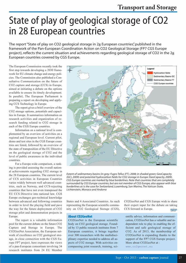
Sept - Oct 2013 - carbon capture journal 27
Transport and Storage
The European Commission recently took the
first step towards developing a 2030 frame-
work for EU climate change and energy poli-
cies. The Commission also published a Con-
sultative Communication on the future of
CO2 capture and storage (CCS) in Europe,
aimed at initiating a debate on the options
available to ensure its timely development.
In parallel, The European Parliament is
preparing a report on developing and apply-
ing CCS Technology in Europe.
The report gives a brief overview of the
CO2 storage options, potentials and capaci-
ties in Europe. It summarizes information on
research activities and organization of re-
search funding related to CO2 storage in
each of the CGS Europe countries.
Information on a national level is com-
plemented by an overview of activities on a
regional and European level. Current pilot,
demo and test sites in the CGS Europe coun-
tries are listed, followed by an overview of
the state of transposition of the EU Directive
on the geological storage of CO2 and the
level of public awareness in the individual
countries.
For a Europe-wide comparison, a rank-
ing is provided assessing the overall nation-
al achievements regarding CO2 storage in
the 28 European countries. The current level
of CCS activities in European Countries
varies widely between well advanced coun-
tries, such as Norway, and CCS-rejecting
countries that have not even transposed the
EU CCS Directive into national law. CGS
Europe exchanges geo-technical knowledge
between advanced and following countries
in order to level the playing field and pave
the way for the future deployment of CO2
storage pilot and demonstration projects in
Europe.
The report is a valuable information
pool for the current debate on the future CO2
Capture and Storage in Europe. The
CO2GeoNet Association, the European net-
work of excellence on CO2 geological stor-
age, in close connection with the CGS Eu-
rope FP7 project, here expresses the views
of a pan-European consortium involving 34
research institutes from 24 EU Member
CO2GeoNet and CGS Europe wish to share
their expert input for the debate on taking
CCS forward in Europe.
States and 4 Associated Countries. As such
representing the European scientific commu-
nity on CO2 Geological Storage (CGS),
State of play of geological storage of CO2in 28 European countriesThe report “State of play on CO2 geological storage in 28 European countries”, published in theframework of the Pan-European Coordination Action on CO2 Geological Storage (FP7 CGS Europeproject), reflects the current situation and achievements regarding geological storage of CO2 in the 28European countries covered by CGS Europe.
Extent of sedimentary basins (in grey: Fugro Tellus (FT), 2008; in shaded green: GeoCapacity(GC), 2009) and potential hydrocarbon fields for CO2 storage in Europe (GeoCapacity, 2009).CGS Europe countries are marked by blue borderlines. Note that countries that are completelysurrounded by CGS Europe countries, but are not member of CGS Europe, also appear with blueborderlines as is the case for Switzerland, Luxemburg, San Marino, The Vatican State,Lichtenstein, Monaco and Andorra
entific advice, information and communi-
cation, CO2GeoNet has a valuable and in-
dependent role to play in enabling the ef-
ficient and safe geological storage of
CO2. As of 2013, the membership of
CO2GeoNet is expanding thanks to the
support of the FP7 CGS Europe project.
More about CO2GeoNet at :
www.co2geonet.eu
About CO2GeoNet CO2GeoNet is the European scientific
body on CO2 geological storage. Found-
ed by 13 public research institutes from 7
European countries, it brings together
over 300 researchers with the multidisci-
plinary expertise needed to address all as-
pects of CO2 storage. With activities en-
compassing joint research, training, sci-
CCJ35_Layout 1 06/09/2013 18:53 Page 27
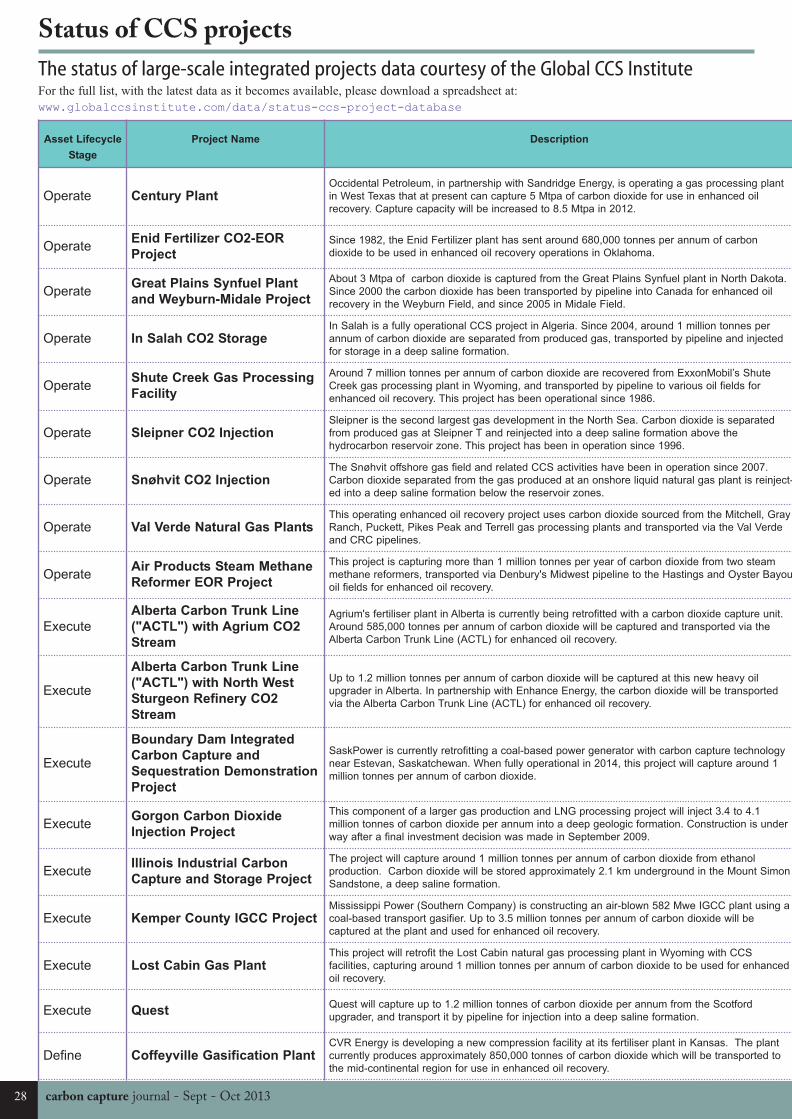
carbon capture journal - Sept - Oct 201328
Status of CCS projects
The status of large-scale integrated projects data courtesy of the Global CCS InstituteFor the full list, with the latest data as it becomes available, please download a spreadsheet at:
www.globalccsinstitute.com/data/status-ccs-project-database
Asset Lifecycle
Stage
Project Name Description State /
Operate Century PlantOccidental Petroleum, in partnership with Sandridge Energy, is operating a gas processing plant
in West Texas that at present can capture 5 Mtpa of carbon dioxide for use in enhanced oil
recovery. Capture capacity will be increased to 8.5 Mtpa in 2012.
Texas
OperateEnid Fertilizer CO2-EOR
ProjectSince 1982, the Enid Fertilizer plant has sent around 680,000 tonnes per annum of carbon
dioxide to be used in enhanced oil recovery operations in Oklahoma.Oklaho
OperateGreat Plains Synfuel Plant
and Weyburn-Midale Project
About 3 Mtpa of carbon dioxide is captured from the Great Plains Synfuel plant in North Dakota.
Since 2000 the carbon dioxide has been transported by pipeline into Canada for enhanced oil
recovery in the Weyburn Field, and since 2005 in Midale Field.
Saskat
Operate In Salah CO2 StorageIn Salah is a fully operational CCS project in Algeria. Since 2004, around 1 million tonnes per
annum of carbon dioxide are separated from produced gas, transported by pipeline and injected
for storage in a deep saline formation.
Wilaya
Ouargl
OperateShute Creek Gas Processing
Facility
Around 7 million tonnes per annum of carbon dioxide are recovered from ExxonMobil’s Shute
Creek gas processing plant in Wyoming, and transported by pipeline to various oil fields for
enhanced oil recovery. This project has been operational since 1986.
Wyomi
Operate Sleipner CO2 InjectionSleipner is the second largest gas development in the North Sea. Carbon dioxide is separated
from produced gas at Sleipner T and reinjected into a deep saline formation above the
hydrocarbon reservoir zone. This project has been in operation since 1996.
North S
Operate Snøhvit CO2 InjectionThe Snøhvit offshore gas field and related CCS activities have been in operation since 2007.
Carbon dioxide separated from the gas produced at an onshore liquid natural gas plant is reinject-
ed into a deep saline formation below the reservoir zones.
Barent
Operate Val Verde Natural Gas PlantsThis operating enhanced oil recovery project uses carbon dioxide sourced from the Mitchell, Gray
Ranch, Puckett, Pikes Peak and Terrell gas processing plants and transported via the Val Verde
and CRC pipelines.
Texas
OperateAir Products Steam Methane
Reformer EOR Project
This project is capturing more than 1 million tonnes per year of carbon dioxide from two steam
methane reformers, transported via Denbury's Midwest pipeline to the Hastings and Oyster Bayou
oil fields for enhanced oil recovery.
Texas
Execute
Alberta Carbon Trunk Line
("ACTL") with Agrium CO2
Stream
Agrium's fertiliser plant in Alberta is currently being retrofitted with a carbon dioxide capture unit.
Around 585,000 tonnes per annum of carbon dioxide will be captured and transported via the
Alberta Carbon Trunk Line (ACTL) for enhanced oil recovery.
Alberta
Execute
Alberta Carbon Trunk Line
("ACTL") with North West
Sturgeon Refinery CO2
Stream
Up to 1.2 million tonnes per annum of carbon dioxide will be captured at this new heavy oil
upgrader in Alberta. In partnership with Enhance Energy, the carbon dioxide will be transported
via the Alberta Carbon Trunk Line (ACTL) for enhanced oil recovery.
Alberta
Execute
Boundary Dam Integrated
Carbon Capture and
Sequestration Demonstration
Project
SaskPower is currently retrofitting a coal-based power generator with carbon capture technology
near Estevan, Saskatchewan. When fully operational in 2014, this project will capture around 1
million tonnes per annum of carbon dioxide.
Saskat
ExecuteGorgon Carbon Dioxide
Injection Project
This component of a larger gas production and LNG processing project will inject 3.4 to 4.1
million tonnes of carbon dioxide per annum into a deep geologic formation. Construction is under
way after a final investment decision was made in September 2009.
Wester
Austra
ExecuteIllinois Industrial Carbon
Capture and Storage Project
The project will capture around 1 million tonnes per annum of carbon dioxide from ethanol
production. Carbon dioxide will be stored approximately 2.1 km underground in the Mount Simon
Sandstone, a deep saline formation.
Illinois
Execute Kemper County IGCC ProjectMississippi Power (Southern Company) is constructing an air-blown 582 Mwe IGCC plant using a
coal-based transport gasifier. Up to 3.5 million tonnes per annum of carbon dioxide will be
captured at the plant and used for enhanced oil recovery.
Mississ
Execute Lost Cabin Gas PlantThis project will retrofit the Lost Cabin natural gas processing plant in Wyoming with CCS
facilities, capturing around 1 million tonnes per annum of carbon dioxide to be used for enhanced
oil recovery.
Wyomi
Execute QuestQuest will capture up to 1.2 million tonnes of carbon dioxide per annum from the Scotford
upgrader, and transport it by pipeline for injection into a deep saline formation.Alberta
Define Coffeyville Gasification PlantCVR Energy is developing a new compression facility at its fertiliser plant in Kansas. The plant
currently produces approximately 850,000 tonnes of carbon dioxide which will be transported to
the mid-continental region for use in enhanced oil recovery.
Kansas
CCJ35_Layout 1 06/09/2013 18:53 Page 28

Sept - Oct 2013 - carbon capture journal 29
Status of CCS projects
State / District Country Volume
CO2
Operation
Date
Facility
Details
Capture Type Transport
Length
Transport
Type
Storage Type Project URL
g plant
il TexasUNITED
STATES8.4 Mtpa 2010
Natural Gas
Processing
Pre-Combustion
(Gas Processing)256 km
Onshore to on-
shore pipeline
Enhanced Oil
Recoveryhttp://www.oxy.com/
nOklahoma
UNITED
STATES0.68 Mtpa 1982
Fertiliser
ProductionPre-Combustion 225 km
Onshore to on-
shore pipeline
Enhanced Oil
Recoveryhttp://www.kochfertilizer.com/
Dakota.
d oil Saskatchewan CANADA 3 Mtpa 2000Synthetic
Natural GasPre-Combustion 315 km
Onshore to on-
shore pipeline
Enhanced Oil
Recoveryhttp://www.cenovus.com/
per
jectedWilaya de
OuarglaALGERIA 1 Mtpa 2004
Natural Gas
Processing
Pre-Combustion
(Gas Processing)14 km
Onshore to on-
shore pipeline
Onshore Deep
Saline
Formations
http://www.insalahco2.com/
hute
or WyomingUNITED
STATES7 Mtpa 1986
Natural Gas
Processing
Pre-Combustion
(Gas Processing)190 km
Onshore to on-
shore pipeline
Enhanced Oil
Recoveryhttp://www.exxonmobil.com
ated
North Sea NORWAY 1 Mtpa 1996Natural Gas
Processing
Pre-Combustion
(Gas Processing)0 km Direct injection
Offshore Deep
Saline
Formations
http://www.statoil.com/en/
07.
reinject- Barents Sea NORWAY 0.7 Mtpa 2008Natural Gas
Processing
Pre-Combustion
(Gas Processing)152 km
Onshore to
offshore
pipeline
Offshore Deep
Saline
Formations
http://www.statoil.com/en/
ell, Gray
Verde TexasUNITED
STATES1.3 Mtpa 1972
Natural Gas
Processing
Pre-Combustion
(Gas Processing)132 km
Onshore to on-
shore pipeline
Enhanced Oil
Recoveryhttp://www.exxonmobil.com/
team
er Bayou TexasUNITED
STATES1 Mtpa 2013
Hydrogen
ProductionPost-Combustion
101 – 150
km
Onshore to on-
shore pipeline
Enhanced Oil
Recoveryhttp://www.airproducts.com/
e unit.
the Alberta CANADA
Up to 0.59
Mtpa
(initially 0.29
Mtpa)
2014Fertiliser
ProductionPre-Combustion 240 km
Onshore to on-
shore pipeline
Enhanced Oil
Recoveryhttp://www.agrium.com/
il
orted Alberta CANADA 1.2 Mtpa 2015 Oil Refining Pre-Combustion 240 kmOnshore to on-
shore pipeline
Enhanced Oil
Recovery
http://www.northwestupgradin
g.com/
nology
und 1 Saskatchewan CANADA 1 Mtpa 2014Power
GenerationPost-Combustion 100 km
Onshore to on-
shore pipeline
Enhanced Oil
Recoveryhttp://www.saskpower.com/
1
s underWestern
AustraliaAUSTRALIA
3.4 -
4.1Mtpa2015
Natural Gas
Processing
Pre-Combustion
(Gas Processing)7 km
Onshore to on-
shore pipeline
Onshore Deep
Saline
Formations
http://www.chevronaustralia.c
om/
l
t Simon IllinoisUNITED
STATES1 Mtpa 2013
Chemical
Production
Industrial
Separation1.6 km
Onshore to on-
shore pipeline
Onshore Deep
Saline
Formations
http://www.adm.com/
using a
MississippiUNITED
STATES3.5 Mtpa 2014
Power
GenerationPre-Combustion 75 km
Onshore to on-
shore pipeline
Enhanced Oil
Recovery
http://www.mississippipower.c
om/
hanced WyomingUNITED
STATES1 Mtpa 2013
Natural Gas
Processing
Pre-Combustion
(Gas Processing)
Not
specified
Onshore to on-
shore pipeline
Enhanced Oil
Recovery
http://www.conocophillips.com
/
Alberta CANADA 1.08 Mtpa 2015Hydrogen
ProductionPre-Combustion 84 km
Onshore to on-
shore pipeline
Onshore Deep
Saline
Formations
http://www.shell.ca/
plant
ted to KansasUNITED
STATES0.85 Mtpa 2013
Fertiliser
ProductionPre-Combustion 112 km
Onshore to on-
shore pipeline
Enhanced Oil
Recoveryhttp://www.cvrenergy.com/
CCJ35_Layout 1 06/09/2013 18:53 Page 29

TriGen produces clean energy, pure water and ‘reservoir ready’ CO2 by burning
natural gas with pure oxygen. �e oxygen is first obtained from an Air Separation Unit (ASU) that also produces significant quantities of nitrogen that can be used for fertilizer or reservoir pressure maintenance.
As all of the TriGen products are useful, it enables zero emission energy from fossil fuels. Maersk Oil is working with Siemens and Clean Energy Systems (CES) on commercial scale power plants. A single train TriGen plant can deliver:
180 MW clean electrici� net
500,000 gallons/day pure water
45 mmcfd ‘reservoir ready’ CO2 which can then produce ca. 7,000 bbls/d incremental oil via Enhanced Oil Recovery (EOR)
Explore more at maerskoil.com and maerskoiltrigen.com
�e TriGen™ Oxycombustion Process by Maersk OilClean power for over 100,000 homes while boosting oil recovery
Net electric power180 MWe
Pure water0.5 MGD
Enhanced OilProduction
~ 7,000 bpd
Separation
Gas reservoir Oil reservoir
Separation
CO
2 4
5 m
mcf
/d
45
mm
cf/d
Gas (+CO2)
Oil
Associated gas with CO2
Air SeparationUnit (ASU)
OxyFuel Gas Combustor Gas/Steam Turbine Generator
O2
N2
Nitrogen
TriGen delivers full carbon capture with commerciali�
Gas (+C
ogen
2
Nitr2
N
O
)2
OGas (+C
d
Gas r
/4
5m
mcff
/
as with C
oir
Associated g
eservGas r
2
ation
Oas with C
Separ
oir
Oil
d 4
5 m
mcf
ationSepar
eservOil r
d/4
5m
mcff
/2
CO
won paelC
ire T�
00,00r 1evr oor few
mocyx™ Onn™eGi
ooe blihs wemo0 h0
orn Poitsubm
yrevocel rig onitso
reay Ms bseco
Enhanced Oil
lik Osr
SU) that also prUnit (Aas with pural gnaturoduces clean enerriGen prTTr
e180 MWWeet electric powN
oduces significant quantities of nitrSU) that also prgen. �e oxye oas with pur
, purgyoduces clean ener
eret electric pow0.5 MGDPur
oduces significant quantities of nitrt obtained frgen is firsxygen. �e oeserve water and ‘r, pur
0.5 MGDtere waPur
ogen that can be usedoduces significant quantities of nitrom an Air Separt obtained fr
y burning b2
Oeady’ Coir reserv
~ 7,000 bpdProductionEnhanced Oil
ogen that can be usedationom an Air Separ
y burning
eserv45 mmcfd ‘r
allons/500,000 g
180 MW clean electrici� net
gy Sysand Clean EnerriGeAs all of the TTr
er or rertilizfor fSU) that also prUnit (A
which can then pr2
Oeady’ Coir reserv
e watery purdaallons/
180 MW clean electrici� net
cial scale poommerS) on ctems (CEgy Sysful, it enables ze useoducts arriGen pr
essuroir preserver or roduces significant quantities of nitrSU) that also pr
emental oil via Enhanced Oil Recd incroduce ca. 7,000 bbls/ which can then pr
ain TTer plants. A single trwcial scale poom fossil fuels. Maersk Oil is wgy fro emission enererful, it enables z
e maintenance.essuroduces significant quantities of nitr
ery (Evoemental oil via Enhanced Oil Rec
er:riGen plant can delivorking with Siemens om fossil fuels. Maersk Oil is w
ogen that can be usedoduces significant quantities of nitr
OR)ery (E
orking with Siemens
ogen that can be used
maerskoil.ce at e morplorEx
maerskoiltrigen.c and ommaerskoil.c
2
ommaerskoiltrigen.c
CCJ35_Layout 1 06/09/2013 18:53 Page 30