ccc1390h series camera - surveillance-video.com · the ccc1390h series camera has a standard...
TRANSCRIPT
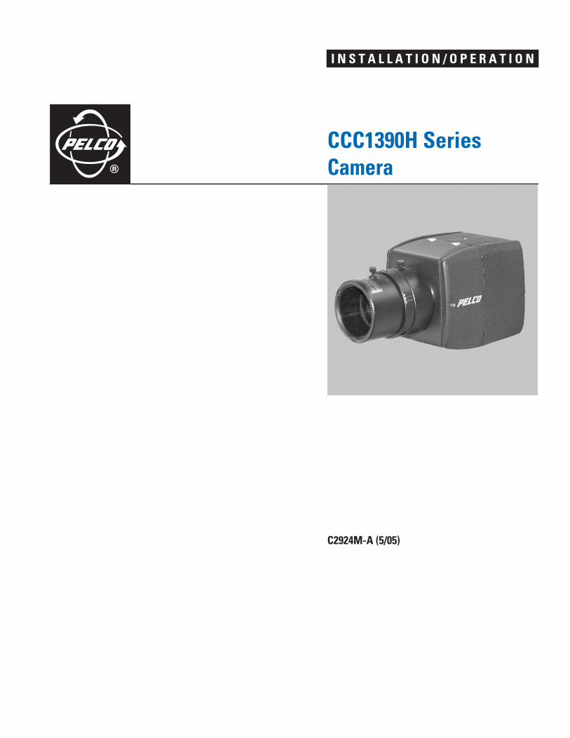
I N S T A L L A T I O N / O P E R A T I O N
CCC1390H Series
Camera
C2924M-A (5/05)


Contents
Regulatory Notices . . . . . . . . . . . . . . . . . . . . . . . . . . . . . . . . . . . . . . . . . . . . . . . . . . . . . . . . . . . . . . . . . . . . . . . . . . . . . . . . . . . . . . . . . . . . . . . . . . . .6
Warnings . . . . . . . . . . . . . . . . . . . . . . . . . . . . . . . . . . . . . . . . . . . . . . . . . . . . . . . . . . . . . . . . . . . . . . . . . . . . . . . . . . . . . . . . . . . . . . . . . . . . . . . . . . . 6
Description . . . . . . . . . . . . . . . . . . . . . . . . . . . . . . . . . . . . . . . . . . . . . . . . . . . . . . . . . . . . . . . . . . . . . . . . . . . . . . . . . . . . . . . . . . . . . . . . . . . . . . . . . .7Product Features . . . . . . . . . . . . . . . . . . . . . . . . . . . . . . . . . . . . . . . . . . . . . . . . . . . . . . . . . . . . . . . . . . . . . . . . . . . . . . . . . . . . . . . . . . . . . . . . .7Models . . . . . . . . . . . . . . . . . . . . . . . . . . . . . . . . . . . . . . . . . . . . . . . . . . . . . . . . . . . . . . . . . . . . . . . . . . . . . . . . . . . . . . . . . . . . . . . . . . . . . . . . .8Parts List . . . . . . . . . . . . . . . . . . . . . . . . . . . . . . . . . . . . . . . . . . . . . . . . . . . . . . . . . . . . . . . . . . . . . . . . . . . . . . . . . . . . . . . . . . . . . . . . . . . . . . .9Optional Accessories . . . . . . . . . . . . . . . . . . . . . . . . . . . . . . . . . . . . . . . . . . . . . . . . . . . . . . . . . . . . . . . . . . . . . . . . . . . . . . . . . . . . . . . . . . . . . .9Required Tools . . . . . . . . . . . . . . . . . . . . . . . . . . . . . . . . . . . . . . . . . . . . . . . . . . . . . . . . . . . . . . . . . . . . . . . . . . . . . . . . . . . . . . . . . . . . . . . . . . .9
Lens Mounting . . . . . . . . . . . . . . . . . . . . . . . . . . . . . . . . . . . . . . . . . . . . . . . . . . . . . . . . . . . . . . . . . . . . . . . . . . . . . . . . . . . . . . . . . . . . . . . . . . . . . .10Wiring an Auto Iris Lens . . . . . . . . . . . . . . . . . . . . . . . . . . . . . . . . . . . . . . . . . . . . . . . . . . . . . . . . . . . . . . . . . . . . . . . . . . . . . . . . . . . . . . . . . .10Mounting the Lens . . . . . . . . . . . . . . . . . . . . . . . . . . . . . . . . . . . . . . . . . . . . . . . . . . . . . . . . . . . . . . . . . . . . . . . . . . . . . . . . . . . . . . . . . . . . . . .11
Camera Mounting . . . . . . . . . . . . . . . . . . . . . . . . . . . . . . . . . . . . . . . . . . . . . . . . . . . . . . . . . . . . . . . . . . . . . . . . . . . . . . . . . . . . . . . . . . . . . . . . . . . .12
Connecting Power, Video, and Control . . . . . . . . . . . . . . . . . . . . . . . . . . . . . . . . . . . . . . . . . . . . . . . . . . . . . . . . . . . . . . . . . . . . . . . . . . . . . . . . . . . .13Connecting Power . . . . . . . . . . . . . . . . . . . . . . . . . . . . . . . . . . . . . . . . . . . . . . . . . . . . . . . . . . . . . . . . . . . . . . . . . . . . . . . . . . . . . . . . . . . . . . .13
Connecting AC Power . . . . . . . . . . . . . . . . . . . . . . . . . . . . . . . . . . . . . . . . . . . . . . . . . . . . . . . . . . . . . . . . . . . . . . . . . . . . . . . . . . . . . . . .14Connecting DC Power . . . . . . . . . . . . . . . . . . . . . . . . . . . . . . . . . . . . . . . . . . . . . . . . . . . . . . . . . . . . . . . . . . . . . . . . . . . . . . . . . . . . . . . .15
Connecting Video . . . . . . . . . . . . . . . . . . . . . . . . . . . . . . . . . . . . . . . . . . . . . . . . . . . . . . . . . . . . . . . . . . . . . . . . . . . . . . . . . . . . . . . . . . . . . . . .15Connecting External Control . . . . . . . . . . . . . . . . . . . . . . . . . . . . . . . . . . . . . . . . . . . . . . . . . . . . . . . . . . . . . . . . . . . . . . . . . . . . . . . . . . . . . . .16
Connecting Serial Control (Pelco D/Pelco P) . . . . . . . . . . . . . . . . . . . . . . . . . . . . . . . . . . . . . . . . . . . . . . . . . . . . . . . . . . . . . . . . . . . . . .17Connecting Day/Night Filter Control . . . . . . . . . . . . . . . . . . . . . . . . . . . . . . . . . . . . . . . . . . . . . . . . . . . . . . . . . . . . . . . . . . . . . . . . . . . .18
Quick Setup . . . . . . . . . . . . . . . . . . . . . . . . . . . . . . . . . . . . . . . . . . . . . . . . . . . . . . . . . . . . . . . . . . . . . . . . . . . . . . . . . . . . . . . . . . . . . . . . . . . . . . . . .20
Accessing Setup Menus . . . . . . . . . . . . . . . . . . . . . . . . . . . . . . . . . . . . . . . . . . . . . . . . . . . . . . . . . . . . . . . . . . . . . . . . . . . . . . . . . . . . . . . . . . . . . . .21Navigating Setup Menus from the Rear Panel . . . . . . . . . . . . . . . . . . . . . . . . . . . . . . . . . . . . . . . . . . . . . . . . . . . . . . . . . . . . . . . . . . . . . . . . .21Navigating Setup Menus from a Pelco Controller . . . . . . . . . . . . . . . . . . . . . . . . . . . . . . . . . . . . . . . . . . . . . . . . . . . . . . . . . . . . . . . . . . . . . . .22
Using Preset 95 to Access Setup Menus . . . . . . . . . . . . . . . . . . . . . . . . . . . . . . . . . . . . . . . . . . . . . . . . . . . . . . . . . . . . . . . . . . . . . . . . .22Navigating Setup Menus . . . . . . . . . . . . . . . . . . . . . . . . . . . . . . . . . . . . . . . . . . . . . . . . . . . . . . . . . . . . . . . . . . . . . . . . . . . . . . . . . . . . .23
Setup Menus . . . . . . . . . . . . . . . . . . . . . . . . . . . . . . . . . . . . . . . . . . . . . . . . . . . . . . . . . . . . . . . . . . . . . . . . . . . . . . . . . . . . . . . . . . . . . . . . . . . . . . . .24Main Menu . . . . . . . . . . . . . . . . . . . . . . . . . . . . . . . . . . . . . . . . . . . . . . . . . . . . . . . . . . . . . . . . . . . . . . . . . . . . . . . . . . . . . . . . . . . . . . . . . . . .26
C2924M-A (5/05) 3
Profiles . . . . . . . . . . . . . . . . . . . . . . . . . . . . . . . . . . . . . . . . . . . . . . . . . . . . . . . . . . . . . . . . . . . . . . . . . . . . . . . . . . . . . . . . . . . . . . . . . . . . . . . .26Active . . . . . . . . . . . . . . . . . . . . . . . . . . . . . . . . . . . . . . . . . . . . . . . . . . . . . . . . . . . . . . . . . . . . . . . . . . . . . . . . . . . . . . . . . . . . . . . . . . . .26Save As . . . . . . . . . . . . . . . . . . . . . . . . . . . . . . . . . . . . . . . . . . . . . . . . . . . . . . . . . . . . . . . . . . . . . . . . . . . . . . . . . . . . . . . . . . . . . . . . . . .27
Exposure Settings . . . . . . . . . . . . . . . . . . . . . . . . . . . . . . . . . . . . . . . . . . . . . . . . . . . . . . . . . . . . . . . . . . . . . . . . . . . . . . . . . . . . . . . . . . . . . . .28Auto Exposure . . . . . . . . . . . . . . . . . . . . . . . . . . . . . . . . . . . . . . . . . . . . . . . . . . . . . . . . . . . . . . . . . . . . . . . . . . . . . . . . . . . . . . . . . . . . . .28Video Level . . . . . . . . . . . . . . . . . . . . . . . . . . . . . . . . . . . . . . . . . . . . . . . . . . . . . . . . . . . . . . . . . . . . . . . . . . . . . . . . . . . . . . . . . . . . . . . .28Flickerless . . . . . . . . . . . . . . . . . . . . . . . . . . . . . . . . . . . . . . . . . . . . . . . . . . . . . . . . . . . . . . . . . . . . . . . . . . . . . . . . . . . . . . . . . . . . . . . . .28Shutter Speed . . . . . . . . . . . . . . . . . . . . . . . . . . . . . . . . . . . . . . . . . . . . . . . . . . . . . . . . . . . . . . . . . . . . . . . . . . . . . . . . . . . . . . . . . . . . . .29Automatic Gain Control (AGC) . . . . . . . . . . . . . . . . . . . . . . . . . . . . . . . . . . . . . . . . . . . . . . . . . . . . . . . . . . . . . . . . . . . . . . . . . . . . . . . . .29Digital Slow Shutter (DSS (SENS)) . . . . . . . . . . . . . . . . . . . . . . . . . . . . . . . . . . . . . . . . . . . . . . . . . . . . . . . . . . . . . . . . . . . . . . . . . . . . . .29Day and Night . . . . . . . . . . . . . . . . . . . . . . . . . . . . . . . . . . . . . . . . . . . . . . . . . . . . . . . . . . . . . . . . . . . . . . . . . . . . . . . . . . . . . . . . . . . . . .29Day and Night Detection . . . . . . . . . . . . . . . . . . . . . . . . . . . . . . . . . . . . . . . . . . . . . . . . . . . . . . . . . . . . . . . . . . . . . . . . . . . . . . . . . . . . .30Day and Night Filter Limit . . . . . . . . . . . . . . . . . . . . . . . . . . . . . . . . . . . . . . . . . . . . . . . . . . . . . . . . . . . . . . . . . . . . . . . . . . . . . . . . . . . . .30
Function Settings . . . . . . . . . . . . . . . . . . . . . . . . . . . . . . . . . . . . . . . . . . . . . . . . . . . . . . . . . . . . . . . . . . . . . . . . . . . . . . . . . . . . . . . . . . . . . . . .31Line Synchronization . . . . . . . . . . . . . . . . . . . . . . . . . . . . . . . . . . . . . . . . . . . . . . . . . . . . . . . . . . . . . . . . . . . . . . . . . . . . . . . . . . . . . . . . .31White Balance . . . . . . . . . . . . . . . . . . . . . . . . . . . . . . . . . . . . . . . . . . . . . . . . . . . . . . . . . . . . . . . . . . . . . . . . . . . . . . . . . . . . . . . . . . . . .31Manual Red/Blue . . . . . . . . . . . . . . . . . . . . . . . . . . . . . . . . . . . . . . . . . . . . . . . . . . . . . . . . . . . . . . . . . . . . . . . . . . . . . . . . . . . . . . . . . . .32Gamma . . . . . . . . . . . . . . . . . . . . . . . . . . . . . . . . . . . . . . . . . . . . . . . . . . . . . . . . . . . . . . . . . . . . . . . . . . . . . . . . . . . . . . . . . . . . . . . . . . .32Sharpness . . . . . . . . . . . . . . . . . . . . . . . . . . . . . . . . . . . . . . . . . . . . . . . . . . . . . . . . . . . . . . . . . . . . . . . . . . . . . . . . . . . . . . . . . . . . . . . . .32E-Zoom . . . . . . . . . . . . . . . . . . . . . . . . . . . . . . . . . . . . . . . . . . . . . . . . . . . . . . . . . . . . . . . . . . . . . . . . . . . . . . . . . . . . . . . . . . . . . . . . . . .32Masking . . . . . . . . . . . . . . . . . . . . . . . . . . . . . . . . . . . . . . . . . . . . . . . . . . . . . . . . . . . . . . . . . . . . . . . . . . . . . . . . . . . . . . . . . . . . . . . . . .33Title . . . . . . . . . . . . . . . . . . . . . . . . . . . . . . . . . . . . . . . . . . . . . . . . . . . . . . . . . . . . . . . . . . . . . . . . . . . . . . . . . . . . . . . . . . . . . . . . . . . . . .33
Camera Setup . . . . . . . . . . . . . . . . . . . . . . . . . . . . . . . . . . . . . . . . . . . . . . . . . . . . . . . . . . . . . . . . . . . . . . . . . . . . . . . . . . . . . . . . . . . . . . . . . .34Auto Iris Lens Adjustment . . . . . . . . . . . . . . . . . . . . . . . . . . . . . . . . . . . . . . . . . . . . . . . . . . . . . . . . . . . . . . . . . . . . . . . . . . . . . . . . . . . . . . . . .34

Pixel Correction . . . . . . . . . . . . . . . . . . . . . . . . . . . . . . . . . . . . . . . . . . . . . . . . . . . . . . . . . . . . . . . . . . . . . . . . . . . . . . . . . . . . . . . . . . . . . . . . .35System Information . . . . . . . . . . . . . . . . . . . . . . . . . . . . . . . . . . . . . . . . . . . . . . . . . . . . . . . . . . . . . . . . . . . . . . . . . . . . . . . . . . . . . . . . . . . . . .35
Lens Focusing . . . . . . . . . . . . . . . . . . . . . . . . . . . . . . . . . . . . . . . . . . . . . . . . . . . . . . . . . . . . . . . . . . . . . . . . . . . . . . . . . . . . . . . . . . . . . . . . . . . . . . .36
Camera Synchronization . . . . . . . . . . . . . . . . . . . . . . . . . . . . . . . . . . . . . . . . . . . . . . . . . . . . . . . . . . . . . . . . . . . . . . . . . . . . . . . . . . . . . . . . . . . . . . .38
Manual White Balance Calibration . . . . . . . . . . . . . . . . . . . . . . . . . . . . . . . . . . . . . . . . . . . . . . . . . . . . . . . . . . . . . . . . . . . . . . . . . . . . . . . . . . . . . .39
Specifications . . . . . . . . . . . . . . . . . . . . . . . . . . . . . . . . . . . . . . . . . . . . . . . . . . . . . . . . . . . . . . . . . . . . . . . . . . . . . . . . . . . . . . . . . . . . . . . . . . . . . . .40
4 C2924M-A (5/05)
C2924M-A (5/05) 5
List of Illustrations
1 CCC1390H Series Camera . . . . . . . . . . . . . . . . . . . . . . . . . . . . . . . . . . . . . . . . . . . . . . . . . . . . . . . . . . . . . . . . . . . . . . . . . . . . . . . . . . . . . . . .82 DC-Drive Auto Iris Lens Connector. . . . . . . . . . . . . . . . . . . . . . . . . . . . . . . . . . . . . . . . . . . . . . . . . . . . . . . . . . . . . . . . . . . . . . . . . . . . . . . . .103 Mounting Lens to Camera . . . . . . . . . . . . . . . . . . . . . . . . . . . . . . . . . . . . . . . . . . . . . . . . . . . . . . . . . . . . . . . . . . . . . . . . . . . . . . . . . . . . . . .114 Connecting AC Power. . . . . . . . . . . . . . . . . . . . . . . . . . . . . . . . . . . . . . . . . . . . . . . . . . . . . . . . . . . . . . . . . . . . . . . . . . . . . . . . . . . . . . . . . . .145 Connecting DC Power. . . . . . . . . . . . . . . . . . . . . . . . . . . . . . . . . . . . . . . . . . . . . . . . . . . . . . . . . . . . . . . . . . . . . . . . . . . . . . . . . . . . . . . . . . .156 Installing the External Control Connector . . . . . . . . . . . . . . . . . . . . . . . . . . . . . . . . . . . . . . . . . . . . . . . . . . . . . . . . . . . . . . . . . . . . . . . . . . .167 Configuring a Serial Chain . . . . . . . . . . . . . . . . . . . . . . . . . . . . . . . . . . . . . . . . . . . . . . . . . . . . . . . . . . . . . . . . . . . . . . . . . . . . . . . . . . . . . . .178 Day/Night Filter Control Configuration . . . . . . . . . . . . . . . . . . . . . . . . . . . . . . . . . . . . . . . . . . . . . . . . . . . . . . . . . . . . . . . . . . . . . . . . . . . . .199 Quick Setup Indicators and Presses. . . . . . . . . . . . . . . . . . . . . . . . . . . . . . . . . . . . . . . . . . . . . . . . . . . . . . . . . . . . . . . . . . . . . . . . . . . . . . . .20
10 Rear Panel Indicators and Presses. . . . . . . . . . . . . . . . . . . . . . . . . . . . . . . . . . . . . . . . . . . . . . . . . . . . . . . . . . . . . . . . . . . . . . . . . . . . . . . . .2111 Sample Profile Scenes . . . . . . . . . . . . . . . . . . . . . . . . . . . . . . . . . . . . . . . . . . . . . . . . . . . . . . . . . . . . . . . . . . . . . . . . . . . . . . . . . . . . . . . . . .2712 Lens Focus . . . . . . . . . . . . . . . . . . . . . . . . . . . . . . . . . . . . . . . . . . . . . . . . . . . . . . . . . . . . . . . . . . . . . . . . . . . . . . . . . . . . . . . . . . . . . . . . . . .36
List of Tables
A Recommended Wire Gauge and Maximum Wiring Distances . . . . . . . . . . . . . . . . . . . . . . . . . . . . . . . . . . . . . . . . . . . . . . . . . . . . . . . . . . .13B Video Coaxial Cable Requirements . . . . . . . . . . . . . . . . . . . . . . . . . . . . . . . . . . . . . . . . . . . . . . . . . . . . . . . . . . . . . . . . . . . . . . . . . . . . . . . .15C Camera/Controller Settings for KBD200A/KBD300A (Direct Mode) . . . . . . . . . . . . . . . . . . . . . . . . . . . . . . . . . . . . . . . . . . . . . . . . . . . . . . .18D Day/Night Control Signal . . . . . . . . . . . . . . . . . . . . . . . . . . . . . . . . . . . . . . . . . . . . . . . . . . . . . . . . . . . . . . . . . . . . . . . . . . . . . . . . . . . . . . . .18E Rear Panel Buttons and Actions. . . . . . . . . . . . . . . . . . . . . . . . . . . . . . . . . . . . . . . . . . . . . . . . . . . . . . . . . . . . . . . . . . . . . . . . . . . . . . . . . . .21F Pelco Controller Buttons and Actions . . . . . . . . . . . . . . . . . . . . . . . . . . . . . . . . . . . . . . . . . . . . . . . . . . . . . . . . . . . . . . . . . . . . . . . . . . . . . .23G Settings by Profile . . . . . . . . . . . . . . . . . . . . . . . . . . . . . . . . . . . . . . . . . . . . . . . . . . . . . . . . . . . . . . . . . . . . . . . . . . . . . . . . . . . . . . . . . . . . .27
Regulatory Notices
This device complies with Part 15 of the FCC Rules. Operation is subject to the following two conditions: (1) this device may not cause harmful interference, and (2) this device must accept any interference received, including interference that may cause undesired operation.
RADIO AND TELEVISION INTERFERENCE
This equipment has been tested and found to comply with the limits of a Class B digital device, pursuant to Part 15 of the FCC Rules. These limits are designed to provide reasonable protection against harmful interference in a residential installation. This equipment generates, uses, and can radiate radio frequency energy and, if not installed and used in accordance with the instructions, may cause harmful interference to radio communications. However there is no guarantee that the interference will not occur in a particular installation. If this equipment does cause harmful interference to radio or television reception, which can be determined by turning the equipment off and on, the user is encouraged to try to correct the interference by one or more of the following measures:
•
Reorient or relocate the receiving antenna.
•
Increase the separation between the equipment and the receiver.
•
Connect the equipment into an outlet on a circuit different from that to which the receiver is connected.
•
Consult the dealer or an experienced radio/TV technician for help.
You may also find helpful the following booklet, prepared by the FCC: “How to Identify and Resolve Radio-TV Interference Problems.” This booklet is available from the U.S. Government Printing Office, Washington D.C. 20402.
Changes and Modifications not expressly approved by the manufacturer or registrant of this equipment can void your authority to operate this equipment under Federal Communications Commission’s rules.
This Class B digital apparatus complies with Canadian ICES-003.
Cet appareil numérique de la classe B est conforme à la norme NMB-003 du Canada.
Warnings
To avoid damaging your camera, please note the following:
1. The camera has threaded mounting locations on the top and bottom of the case. Use only a standard photographic mounting bolt with a1/4-20 UNC thread.
2. Do not touch the surface of the optical filter. If the filter is dusty or is accidentally touched, use clean, compressed air or lens cleaning paper to clean it.
6 C2924M-A (5/05)
3. Do not expose the camera imager to direct sunlight as this may impair camera performance. Always keep the lens mount cap in place until you install the lens.
4. Do not use this camera outdoors without an appropriate enclosure. Do not install near flammable gas or corrosive chemical fumes.
5. Use a soft dry cloth to clean the camera case. If necessary, use a soft cloth moistened with a neutral detergent diluted with water; then dry with the dry cloth. Never use alcohol, benzene, or other volatile solutions.

Description
The CCC1390H Series camera is a compact, wide dynamic range (WDR), day/night camera. Its WDR technology provides up to 60 dB of dynamic range and produces superior images over a wide range of lighting conditions, including extreme backlight conditions. The camera also uses a removable infrared (IR) cut filter to switch between color and black-white (B-W) modes as environmental lighting conditions change. It also pro-vides a dual resolution of 530 TVL (B-W) and 480 TVL (color).
On-screen programmable menus can be accessed locally using the rear panel button or remotely using any Pelco controller with Pelco P or Pelco D protocol. Use these menus to select a specific profile or to customize and save camera settings for the specific application.
The CCC1390H Series camera has a standard CS-mount and can be used with fixed, manual, or DC-drive auto iris lenses. The auto iris is controlled through a standard four-pin square connector that is included with all Pelco auto iris lenses.
The CCC1390H Series camera is quick and easy to install and is ideal for Pelco’s DomePak
®
and ImagePak
®
fixed camera dome/enclosure packages.
PRODUCT FEATURES
•
Compact Body Style
•
Wide Dynamic Range (60 dB Maximum); Captures Both High-Luminance and Low-Luminance Objects
•
Day/Night with Automatic or Manual Control; Captures High-Quality Color During the Day and Clear B-W Images at Night
•
Electronic Zoom
•
1/3-Inch Format Sony
®
SS-2WD CCD Imager
•
Digital Signal Processing
•
530 TV Lines (B-W); 480 TV Lines (Color)
•
On-Screen Menu Configuration
•
Four Preset Application Profiles; One User-Definable Profile
•
Selectable Auto White Balance (AWB), Automatic Gain Control (AGC), and Backlight Compensation (BLC)
•
Electronic Shutter Control (ESC)
•
Digital Slow Shutter (DSS)
•
Flickerless Mode
•
CS Lens Mount (C-Mount Lens Requires Optional Adapter)
•
Autosensing DC-Drive Auto Iris
•
Autosensing 24 VAC/12 VDC with Line Lock or Internal Synchronization
C2924M-A (5/05) 7
• Internal Top/Bottom Mount

Figure 1.
CCC1390H Series Camera
� �
� ��
� ��
3 3a
� Lens Mount: Mount a standard CS-mount lens to the CCC1390H Series camera (refer to Lens Mounting). To use a C-mount lens, install a C/CS-mount adapter.
� Back Focus Locking Screw: Use a 1.5-mm Allen wrench to adjust the back focus (refer to Lens Focusing).
� Camera Mount and 3a Mount Adapter: Use the top or bottom mount hole. The maximum thread depth (top) is 0.188 inches (4.7 mm); the adapter extends the thread depth (top) to 0.25 inches (6.4 mm). The maximum thread depth (bottom) is 0.25 inches (6.4 mm). Refer to Camera Mounting.
� Serial Terminating Switch: Use this switch to terminate the serial signal at the last camera on the serial chain (refer to Connecting External Control).
� Auto Iris Lens Connector: Insert the four-pin connector from the DC-drive auto iris lens into this connector (refer to Lens Mounting).
� Video Output Connector: Connect a coaxial video cable to this BNC connector to output the video image (refer to Connecting Video).
Setup Button: Use this five-position button to configure the camera either directly (refer to Quick Setup) or through the setup menus (refer to Accessing Setup Menus).
8 C2924M-A (5/05)
MODELSCCC1390H-6 1/3-inch high resolution day/night, WDR, CCD camera, 24 VAC or 12 VDC, NTSC format
CCC1390H-6X 1/3-inch high resolution day/night, WDR, CCD camera, 24 VAC or 12 VDC, PAL format
� Power Terminal Strip: Use this three-pin, push-in type terminal strip to connect either 12 VDC or 24 VAC power (refer to Connecting Power).
Indicators: Use these indicators to quickly determine camera status (refer to Quick Setup).
�� External Control Connector: Use this seven-pin connector to connect the camera to one or more serial devices. Use it also to connect an external day/night filter switch. Refer to Connecting External Control for more information.
PARTS LIST
CCC1390H Series camera
Quick Start Guide
Safety Instructions
External control connector assembly: seven-pin micro (1.25 mm) connector with wires (26 AWG) and connector cover
Camera mount spacer
Four-pin auto iris connector (type DN-152N)
Lens mount cap
Resource CD:
•
Installation/Operation manual: INSTALL.PDF
•
Quick Start Guide: QSG.PDF
•
Important Safety Instructions: SAFETY.PDF
OPTIONAL ACCESSORIES
PCMA40 Lens adapter. Adapts standard C-mount lenses to CS-mount cameras.
REQUIRED TOOLS
Small Phillips screwdriver for connector cover
Small flat tip screwdriver for serial termination
Allen wrench (1.5 mm) for back focus adjustment
Neutral density filter (ND3) for auto iris adjustment
C2924M-A (5/05) 9
Lens Mounting
The CCC1390H Series camera supports both manual and DC-drive auto iris lenses, either fixed focal length or varifocal. It automatically senses an auto iris lens as soon as you plug in the connector. The camera has a standard CS-mount that can accept a C-mount lens with a PCMA40 lens adapter.
After mounting an auto iris lens, but before using the camera, perform the auto iris automatic adjustment procedure (refer to
Auto Iris Lens Adjustment)
. Also perform this procedure each time you change the lens.
NOTE:
The CCC1390H Series camera does not support video-drive auto iris lenses.
WIRING AN AUTO IRIS LENS
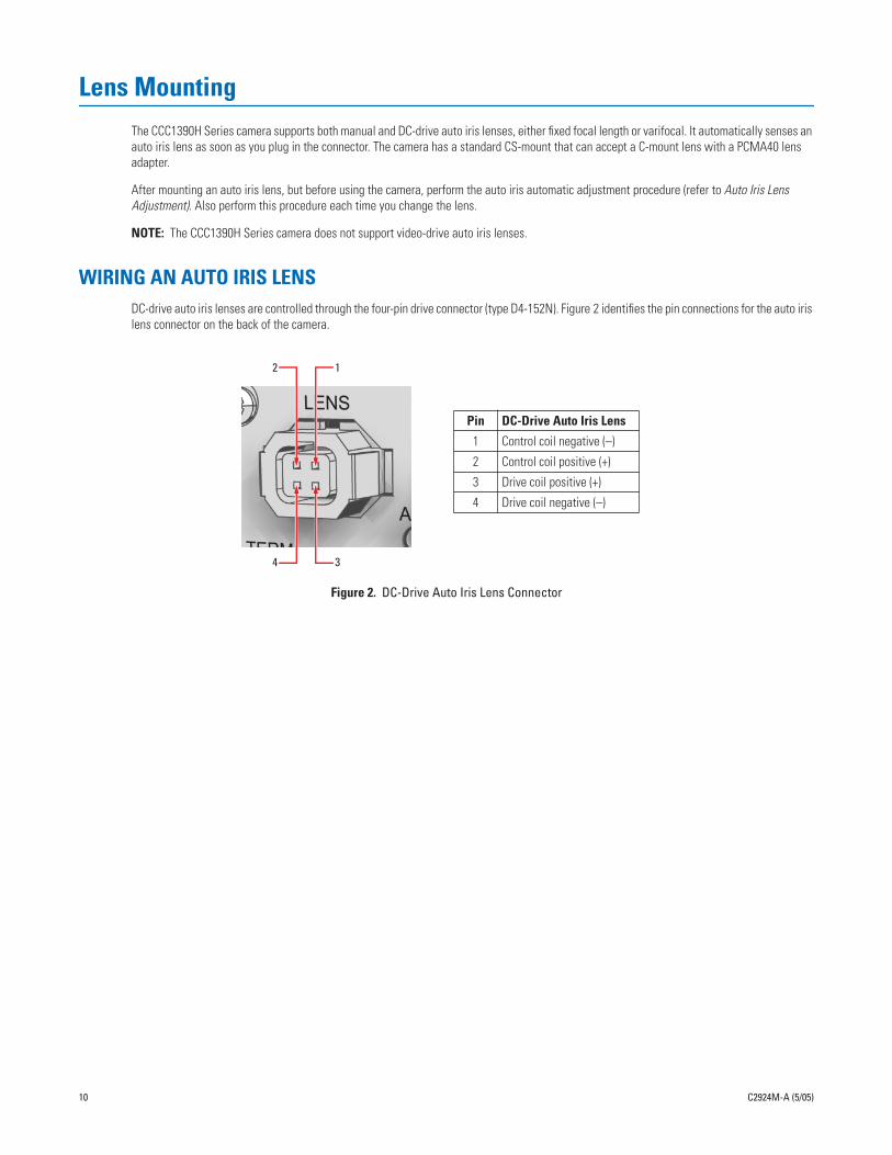
DC-drive auto iris lenses are controlled through the four-pin drive connector (type D4-152N). Figure 2 identifies the pin connections for the auto iris lens connector on the back of the camera.
Figure 2.
DC-Drive Auto Iris Lens Connector
12
34
Pin DC-Drive Auto Iris Lens
1 Control coil negative (–)
2 Control coil positive (+)
3 Drive coil positive (+)
4 Drive coil negative (–)
10 C2924M-A (5/05)
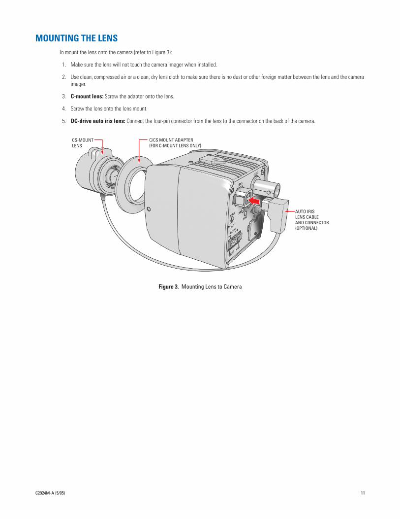
MOUNTING THE LENS
To mount the lens onto the camera (refer to Figure 3):
1. Make sure the lens will not touch the camera imager when installed.
2. Use clean, compressed air or a clean, dry lens cloth to make sure there is no dust or other foreign matter between the lens and the camera imager.
3.
C-mount lens:
Screw the adapter onto the lens.
4. Screw the lens onto the lens mount.
5.
DC-drive auto iris lens:
Connect the four-pin connector from the lens to the connector on the back of the camera.
Figure 3.
Mounting Lens to Camera
CS-MOUNTLENS
AUTO IRISLENS CABLEAND CONNECTOR(OPTIONAL)
C/CS MOUNT ADAPTER(FOR C-MOUNT LENS ONLY)
C2924M-A (5/05) 11
Camera Mounting
The CCC1390H Series camera can be mounted from either the top or bottom, depending on the type of camera mount used in your installation. Use a standard 1/4-20 screw. The maximum thread depth (top) is 0.188 inches (4.7 mm). To extend the thread depth (top) to 0.25 inches (6.4 mm), use the camera mount spacer (supplied). The maximum thread depth (bottom) is 0.25 inches (6.4 mm).
The CCC1390H Series camera can be fitted with most Pelco lenses and mounted into most Pelco domes and enclosures, resulting in the greatest possible number of combinations. This means you can find a solution for nearly any application.
When selecting a lens, dome, or enclosure for this camera, consider how the physical dimensions of each component may affect camera installation and operation. Specifically, you should address the following three issues.
•
Enclosure size:
The camera dimensions are 2.2 (D) x 2.09 (W) x 2.17 (H) inches (5.6 x 5.3 x 5.5 cm). Make sure the enclosure is large enough for both the camera and the lens.
•
Lens size:
Some lenses have minimum and maximum lengths. To focus the scene correctly, you may have to adjust the lens to its maximum length. This could affect how it fits within the enclosure.
•
Optical alignment:
The optical center of this camera may be too low for some enclosures. As a result, the lower portion of the scene may be obstructed by the enclosure itself. The camera sled in many Pelco enclosures has a low side and a high side. You may be able to raise the optical center by flipping the camera sled to the high side.
NOTE:
To simplify lens and enclosure selection, Pelco offers ImagePak options for the CCC1390H Series camera. Select the lens and the dome or enclosure. Pelco will build and test it for you. Contact Pelco or your dealer for more information.
12 C2924M-A (5/05)

Connecting Power, Video, and Control
The CCC1390H Series camera offers standard power and coax video connectors as well as an external control connector. Before installation, identify how you will connect each power, video, and control lead to the camera.
CONNECTING POWER
The CCC1390H Series camera is designed to operate from either a 12 VDC or a 24 VAC power source. The camera automatically senses power type. Use only a Class 2 isolated power source that can supply 12 VDC ±15% or 24 VAC ±15%, 50/60 Hz. Maximum power consumption is about 3.5 watts.
NOTES:
•
Be sure to use 60 Hz power for NTSC (CCC1390H-6) and 50 Hz power for PAL (CCC1390H-6X).
•
Install the camera near a socket or outlet that is easily accessible.
Use Table A to help you identify the necessary wire gauge and maximum cable distance. This table applies to two-conductor solid copper wire. (Reduce distance by 10% for stranded copper wire.) These maximum distances are based on a maximum allowable voltage drop of 10%.
WARNINGS:
•
Do not connect high voltage power to the camera because you may damage the camera.
•
Do not short circuit the power leads when connecting the power supply to the camera.
•
Do not remove the connector cover during camera operation.
Table A.
Recommended Wire Gauge and Maximum Wiring Distances
Wire GaugeMaximum Distance
12 VDC 24 VAC
24 AWG (0.25 mm
2
) 80 ft (24 m) 323 ft (98 m)
22 AWG (0.35 mm
2
) 128 ft (39 m) 513 ft (156 m)
20 AWG (0.5 mm
2
) 203 ft (61 m) 815 ft (248 m)
18 AWG (1.0 mm
2
) 323 ft (98 m) 1,295 ft (394 m)
16 AWG (1.5 mm
2
) 514 ft (156 m) 2,056 ft (626 m)
14 AWG (2.5 mm
2
) 816 ft (248 m) 3,264 ft (994 m)
C2924M-A (5/05) 13
12 AWG (4.0 mm2) 1,295 ft (394 m) 5,183 ft (1,579 m)
10 AWG (6.0 mm2) 2,057 ft (626 m) 8,228 ft (2,507 m)
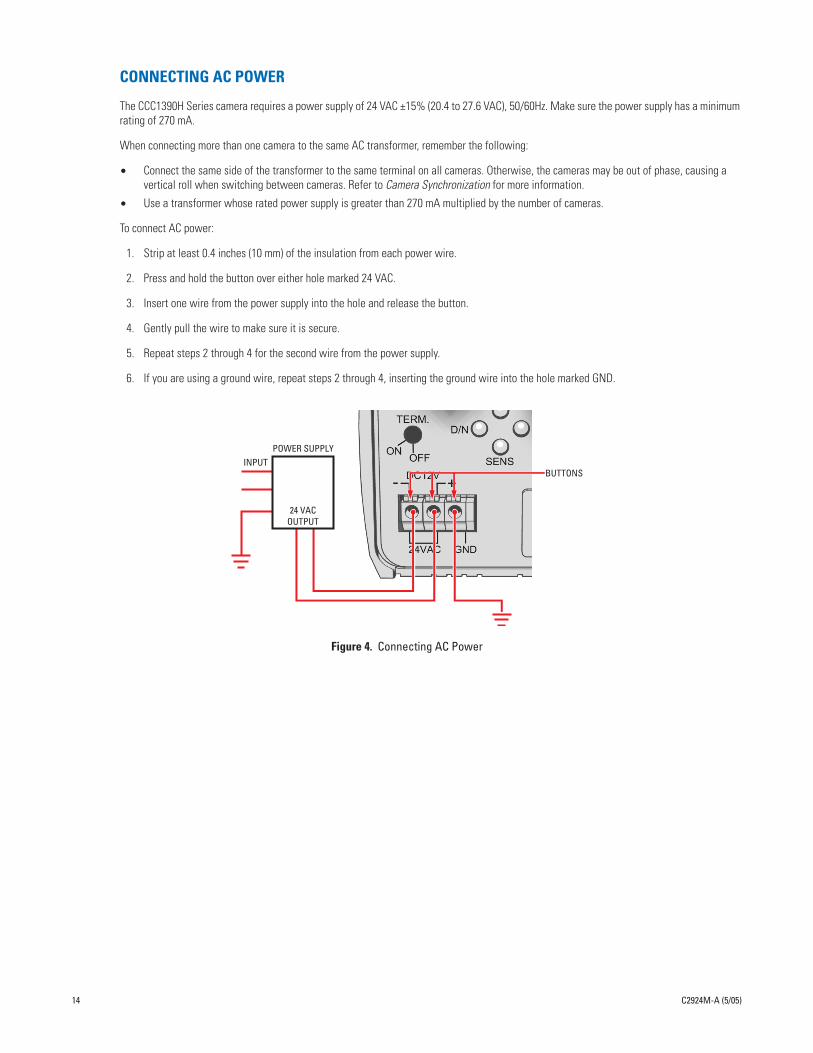
CONNECTING AC POWER
The CCC1390H Series camera requires a power supply of 24 VAC ±15% (20.4 to 27.6 VAC), 50/60Hz. Make sure the power supply has a minimum rating of 270 mA.
When connecting more than one camera to the same AC transformer, remember the following:
•
Connect the same side of the transformer to the same terminal on all cameras. Otherwise, the cameras may be out of phase, causing a vertical roll when switching between cameras. Refer to
Camera Synchronization
for more information.
•
Use a transformer whose rated power supply is greater than 270 mA multiplied by the number of cameras.
To connect AC power:
1. Strip at least 0.4 inches (10 mm) of the insulation from each power wire.
2. Press and hold the button over either hole marked 24 VAC.
3. Insert one wire from the power supply into the hole and release the button.
4. Gently pull the wire to make sure it is secure.
5. Repeat steps 2 through 4 for the second wire from the power supply.
6. If you are using a ground wire, repeat steps 2 through 4, inserting the ground wire into the hole marked GND.
POWER SUPPLYINPUT
24 VACOUTPUT
BUTTONS
14 C2924M-A (5/05)
Figure 4. Connecting AC Power

CONNECTING DC POWER
The CCC1390H Series camera requires a power supply of 12 VDC ±15% (10.2 to 13.8 VDC). Make sure the power supply has a minimum rating of 390 mA.
To connect DC power:
1. Strip at least 0.4 inches (10 mm) of the insulation from each power wire.
2. Press and hold the button over the hole marked (–).
3. Insert the negative wire from the power supply into the hole and release the button.
4. Gently pull the wire to make sure it is secure.
5. Repeat steps 2 through 4 for the positive wire from the power supply. Use the hole marked (+). For safety, add a 1.0 A slow blow fuse to the positive wire from the power supply. The fuse should be less than 4 inches (10 cm) from the positive terminal on the power supply.
WARNINGS:
• For safety, include a 1.0 A slow blow fuse when connecting DC power, as shown in Figure 5.
• The DC power supply must be UL- and CE-certified.
• Make sure you wire the power polarity correctly.
+12VDC
4 INCH (10 CM) MAX.
1.0 A FUSE(SLOW BLOW)
POWERSUPPLY
INPUT
BUTTONS
C2924M-A (5/05) 15
Figure 5. Connecting DC Power
CONNECTING VIDEOConnect a coaxial video cable to the BNC connector on the back of the camera. Refer to Table B for the type of video coaxial cable to use.
*Cable requirements:75 ohms impedanceAll-copper center conductor; steel-center conductor cable may result in poor performanceAll-copper braided shield with 95% braid coverage
If white spots appear in the video image, one or more pixels on the camera imager may be defective. This condition is common to CCD camera imagers. To correct this condition, refer to Pixel Correction.
Table B. Video Coaxial Cable Requirements
Cable Type* Maximum Distance
RG59/U 750 ft (229 m)
RG6/U 1,000 ft (305 m)
RG11/U 1,500 ft (457 m)
GND

CONNECTING EXTERNAL CONTROLThe external control connector on the rear panel lets you remotely access and control the CCC1390H Series camera. The external control connector assembly is a seven-pin micro (1.25 mm) connector with wires (26 AWG) and connector cover.
You can access and configure the menu settings from any Pelco keyboard, receiver, or other device that supports the Pelco D or Pelco P protocol. The camera supports the following settings:
• Baud rate: 2400, 4800, 9600, 19200
• Start bit: 1
• Data bits: 8
• Stop bit: 1
• Parity: None
You can also control day/night filter operation from an external switch.
When connecting external control, the wiring should meet the following requirements:
• 24 AWG (0.25 mm2) or 22 AWG (0.35 mm2)
• Shielded twisted pair
• Up to 4,000 ft (1,219 m) maximum
Figure 6 identifies the pin connections for the enclosed external control connector assembly. It also identifies pins 1 and 7.
REMOVECONNECTORCOVER
Pin Lead Color
1 Pelco Data RX+ Red
2 Pelco Data RX– White
3 Ground Black
4 Pelco Data TX+ Red
16 C2924M-A (5/05)
Figure 6. Installing the External Control Connector
TO CONTROLDEVICE
GND
RX+RX-
INSTALLCONNECTOR
COVER
PIN 7PIN 1
5 Pelco Data TX– White
6 Ground Black
7 Day/Night Control Signal Input Brown
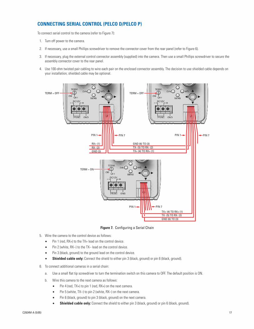
CONNECTING SERIAL CONTROL (PELCO D/PELCO P)
To connect serial control to the camera (refer to Figure 7):
1. Turn off power to the camera.
2. If necessary, use a small Phillips screwdriver to remove the connector cover from the rear panel (refer to Figure 6).
3. If necessary, plug the external control connector assembly (supplied) into the camera. Then use a small Phillips screwdriver to secure the assembly connector cover to the rear panel.
4. Use 100-ohm twisted pair cabling to wire each pair on the enclosed connector assembly. The decision to use shielded cable depends on your installation; shielded cable may be optional.
TERM = OFF TERM = OFF
TERM = ON
GND (6) TO (3)TX- (5) TO RX- (2)TX+ (4) TO RX+ (1)
PIN 7PIN 1
RX+ (1)RX- (2)GND (3)
PIN 7PIN 1
C2924M-A (5/05) 17
Figure 7. Configuring a Serial Chain
5. Wire the camera to the control device as follows:
• Pin 1 (red, RX+) to the TX+ lead on the control device.
• Pin 2 (white, RX–) to the TX– lead on the control device.
• Pin 3 (black, ground) to the ground lead on the control device.
• Shielded cable only: Connect the shield to either pin 3 (black, ground) or pin 6 (black, ground).
6. To connect additional cameras in a serial chain:
a. Use a small flat tip screwdriver to turn the termination switch on this camera to OFF. The default position is ON.
b. Wire this camera to the next camera as follows:
• Pin 4 (red, TX+) to pin 1 (red, RX+) on the next camera.
• Pin 5 (white, TX–) to pin 2 (white, RX–) on the next camera.
• Pin 6 (black, ground) to pin 3 (black, ground) on the next camera.
• Shielded cable only: Connect the shield to either pin 3 (black, ground) or pin 6 (black, ground).
GND (6) TO (3)TX- (5) TO RX- (2)TX+ (4) TO RX+ (1)
PIN 1 PIN 7

7. If you are not connecting additional cameras, or after adding all cameras to the chain, make sure you set the termination switch to ON for the last camera in the chain.
8. Access the CAMERA SETUP menu to set the following (refer to Camera Setup):
• Set a unique ADDRESS for each camera on the serial chain.
• Set the communication rate (COM SPEED) to match the rate of each camera on the serial chain.
Table C lists the ADDRESS and COM SPEED by Pelco protocol for accessing the camera from a Pelco KBD200A or KBD300A.
*To select the camera using the Pelco P protocol, add one to the camera number at the controller. For example, if the ADDRESS at the camera is set to 10, select camera 11 at the controller.
CONNECTING DAY/NIGHT FILTER CONTROL
In some installations, high infrared (IR) illumination or other light sources may interfere with the camera’s automatic day/night mode operation. Use an external day/night filter switch, such as a photosensor, to keep the camera from constantly switching filters.
The control signal input responds as shown in Table D:
NOTES:
• Do not exceed these values.
• The CCC1390H Series camera responds only to the input signal from the switch. It does not provide enough power to drive an external
Table C. Camera/Controller Settings for KBD200A/KBD300A (Direct Mode)
Equipment Parameter PELCO D PELCO P
Camera ADDRESS 1-30 1-30
COM SPEED 2400 4800
Keyboard ADDRESS 1-30 2-31*
DIP SWITCH ON: 5, 7OFF: all others
ON: 5OFF: all others
Table D. Day/Night Control Signal
Signal Voltage D/N Mode
Open or High 3.0V to 3.3V AUTO
Short or Low -0.3V to 0.3V BW
18 C2924M-A (5/05)
device.
To connect an external day/night filter switch to the camera (refer to Figure 8):
1. Turn off power to the camera.
2. If necessary, use a small Phillips screwdriver to remove the connector cover from the rear panel (refer to Figure 6).
3. If necessary, plug the external control connector assembly (supplied) into the camera. Then use a small Phillips screwdriver to secure the assembly cover to the rear panel.

4. Use 100-ohm twisted pair cabling to wire the device to the enclosed connector assembly. The decision to use shielded cable depends on your installation; shielded cable may be optional.
Figure 8. Day/Night Filter Control Configuration
5. Wire the camera to the external switch as follows:
• Pin 7 (brown, signal input) to the (+) lead on the external switch.
• Pin 6 (black, ground) to the (–) lead on the external switch.
• Shielded cable only: Connect the shield to either pin 3 (black, ground) or pin 6 (black, ground).
6. Change DAY & NIGHT to EXT. (external) on the EXPOSURE SETTINGS menu.
7. Configure the external switch as follows:
• Open or High: Camera operates in AUTO mode.
• Short or Low: Camera operates in BW mode.
INPUT (7)GND (6)
EXTERNAL SWITCH
PIN 7PIN 1
C2924M-A (5/05) 19

Quick SetupSeveral CCC1390H Series camera settings can be changed directly from the rear panel button. When a rear panel indicator is lit, the correspond-ing option is enabled. You can change the following options directly from the rear panel:
AGC Press the button up to enable or disable automatic gain control (AGC). Refer to Automatic Gain Control (AGC) for more information.
D/N Press the button left to enable or disable day and night mode. When enabled, the AUTO mode is selected. When disabled, the COLOR mode is selected. Refer to Day and Night for more information.
You cannot change day and night mode when AGC is disabled; the camera uses the COLOR mode.
SENS Press the button down to enable or disable DSS (SENS). Refer to Digital Slow Shutter (DSS (SENS)) for more information.
If you disable SENS on the rear panel, the camera saves the DSS (SENS) value on the EXPOSURE SETTING menu.
WD Press the button right to change the auto exposure mode. When this indicator is lit, WDR is selected. Otherwise, the NORMAL auto exposure mode is selected. Refer to Auto Exposure for more information.
NOTES:
• To enable the rear panel indicators, the LED setting on the CAMERA SETUP menu must be set to ON (the default).
• To enable the quick setup feature, the SWITCH setting on the CAMERA SETUP menu must be set to ON (the default).
Figure 9 shows the rear panel indicators and their corresponding button presses.
AGC
WD
20 C2924M-A (5/05)
Figure 9. Quick Setup Indicators and Presses
SENS
D/N

Accessing Setup Menus
NAVIGATING SETUP MENUS FROM THE REAR PANELYou can use the five-position button on the rear panel to access and navigate the setup menus (refer to Figure 10).
Figure 10. Rear Panel Indicators and Presses
Table E lists the button presses for each menu action.
Table E. Rear Panel Buttons and Actions
MENU ACTION BUTTON ACTION
Enter setup menus. Long center press
Move up or down in menu or item options. Up or down press
Move right or left in menu. Right or left press
Select menu or item. Short center press
Save setting and exit to menu. Short center press
UP
RIGHT
DOWN
LEFT
SELECT
C2924M-A (5/05) 21
To display a menu:
1. Press and hold the button for two seconds to open the MAIN MENU. The four indicators on the rear panel blink until you close the setup menu.
2. Press the button up or down to select a menu.
3. Press the center of the button to open the menu.
To change a setting:
1. Press the button up or down to select the item.
2. Press the center of the button to open the item.
3. Press the button up or down to move through the options.
4. Press the center of the button to save the setting and return to the menu.
To move to a previous menu, select BACK and press the center of the button.
To close the setup menus, select EXIT from any menu and press the center of the button.
NOTES:
• When you select BACK or EXIT on any menu, the camera saves the current settings into memory.
• The menu closes automatically after three minutes of inactivity.

NAVIGATING SETUP MENUS FROM A PELCO CONTROLLER
USING PRESET 95 TO ACCESS SETUP MENUS
You can use preset 95 to access and navigate the setup menus from various Pelco controllers. Use the instructions for your controller to access the main menu.
CM6700/CM6800
1. Enter the camera number and press the CAM key.
2. Enter 95 and hold the PRESET key for two seconds. A menu screen appears.
3. Move the joystick down to highlight SET.
4. Move the joystick right. The MAIN MENU appears.
KBD200A/KBD300A (Direct Mode)
1. Enter the camera number and press the CAM key.
2. Enter 95.
3. Press the PRESET key. The MAIN MENU appears.
CM9740/CM9760/CM9770/CM9780
1. Press the ESCAPE key to open the Main menu. Select DEF. The Define Submenu appears.
2. Enter your four-digit PIN if this is your first time entering this mode.
3. Enter 95 and select PRST. The MAIN MENU appears on the monitor.
4. Select the Quit icon to return to the default menu.
MPT9500 (RS-485 Mode)
1. Enter 95 and press the PRESET SET key.
2. Press the F2 key. The MAIN MENU appears.
PelcoNet™
22 C2924M-A (5/05)
1. Check the Set box.
2. Click the preset 95 button. The MAIN MENU appears.

NAVIGATING SETUP MENUS
As soon as you access the MAIN MENU, the four indicators on the rear panel blink until you close the setup menu. Table F lists the buttons and actions for menu navigation.
NOTE: If your Pelco controller does not have a joystick, use the up, down, right, and left buttons.
To display a menu:
1. Use the joystick to select a menu.
2. Press the iris open button to open the menu.
To change a setting:
1. Use the joystick to select the item.
2. Press the iris open button to open the item.
3. Move the joystick up or down to move through the options.
4. Press the iris open button to save the setting and return to the menu.
To move to a previous menu, select BACK and press the iris open button.
To close the setup menus, select EXIT from any menu and press the iris open button.
NOTES:
• When you select BACK or EXIT on any menu, the camera saves the current settings into memory.
• The menu closes automatically after three minutes of inactivity.
• The rest of this document describes navigating the menus from the rear panel button. Refer to Table F for the equivalent Pelco controller
Table F. Pelco Controller Buttons and Actions
MENU ACTION BUTTON ACTION
Move up or down in menu or item options. Move joystick up or down.
Move right or left in menu. Move joystick right or left.
Select menu or item. Press the iris open button.
Save setting and exit to menu. Press the iris open button.
C2924M-A (5/05) 23
commands.

Setup MenusThe CCC1390H Series camera uses setup menus instead of hardware switches for configuring the camera. As a result, you have more options for customizing the camera for its specific application.
NOTES:
• After you customize any aspect of the CCC1390H Series camera, be sure to save your custom settings. (Refer to Profiles for information about saving custom settings.)
• Menu items that cannot be changed are either disabled or marked with an asterisk (*).
• FLICKERLESS changes to SHUTTER SPEED when AUTO EXPOSURE mode is set to MANUAL.
The setup menu tree is represented on this and the next page:
MAIN MENU
PROFILES >EXPOSURE SETTINGS >FUNCTION SETTINGS >CAMERA SETUP >AI AUTO ADJUSTMENT >PIXEL CORRECTION >SYSTEM INFORMATION >
EXIT
PROFILES
ACTIVE > STANDARDSAVE AS > CUSTOM*DEFAULT STANDARD
BACK EXIT
EXPOSURE SETTINGS
AUTO EXPOSURE > NORMALVIDEO LEVEL > 0FLICKERLESS > OFFAGC > ONDSS(SENS) > 4DAY & NIGHT > COLORD&N DETECTION >D&N FILTER LIMIT >BACK EXIT
FUNCTION SETTINGS
LINE SYNC >WHITE BALANCE > AUTOMANUAL RED/BLUE >
AI AUTO ADJUSTMENT
OK CANCEL
PIXEL CORRECTION
COVER THE LENSAND SELECT OK
OK CANCEL
SYSTEM INFORMATION
FIRMWARE VERSION 1.0OSD VERSION 1.0
RESTORE FACTORY SETTINGS >
BACK EXIT
RESTORE FACTORY SETTINGS
OK CANCEL
24 C2924M-A (5/05)
GAMMA > 60%(NORM)SHARPNESS >E-ZOOM >MASKING >TITLE >BACK EXIT
CAMERA SETUP
ADDRESS > 1COM SPEED > 4800LED > ONSWITCH > ON
BACK EXIT

LINE SYNC
LINE SYNC > AUTOV-PHASE ADJ >
BACK EXIT
V-PHASE ADJ
PHASE VALUE = 45
MANUAL RED/BLUE
RED GAIN > -1BLUE GAIN > -2RED HUE > 1BLUE HUE > 1
BACK EXIT
SHARPNESS
APERTURE GAIN > -1
BACK EXIT
E-ZOOM
ZOOM > OFFPOSITION >
BACK EXIT
POSITION
MASKING MASK SETTING
C2924M-A (5/05) 25
MASK > OFFMASK EDIT >MASK ERASE
BACK EXIT
TITLE
TITLE > OFFEDIT TITLE >
BACK EXIT
EDIT TITLE
ABCDEFGHIJKLMNOPQRSTUVWXYZabcdefghijklmnopqrstuvwxyz 0123456789-/
BACK BS
_________________
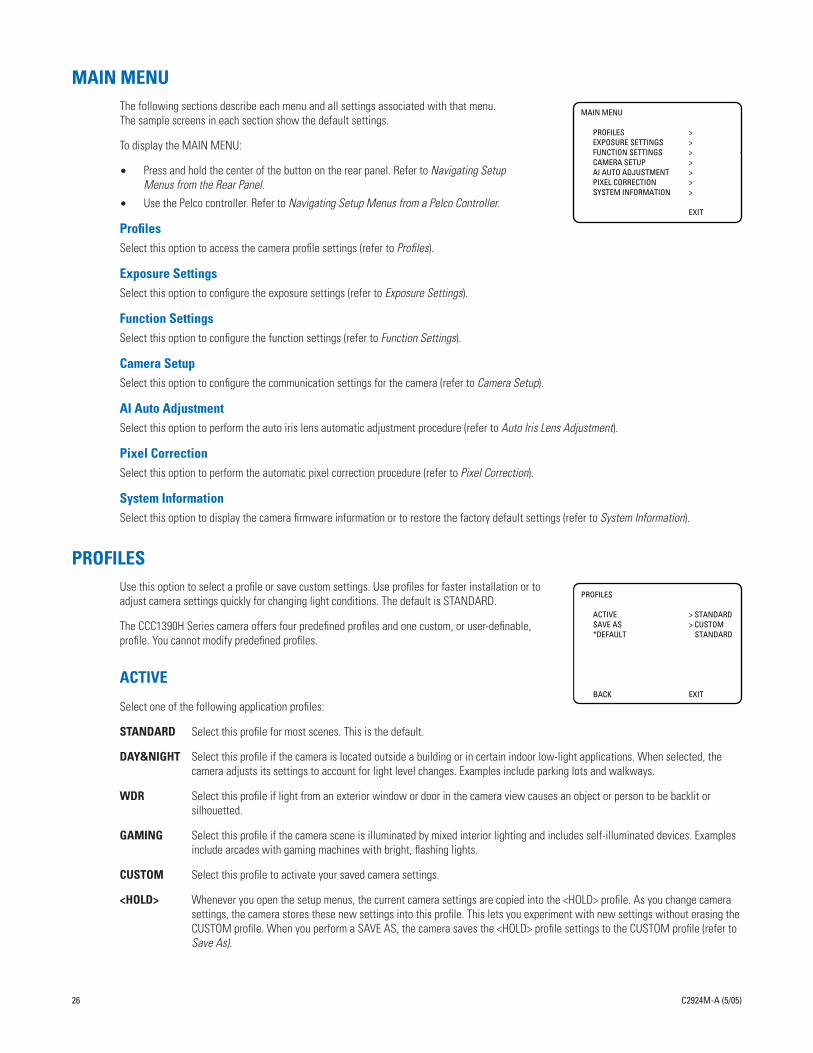
MAIN MENUThe following sections describe each menu and all settings associated with that menu. The sample screens in each section show the default settings.
To display the MAIN MENU:
• Press and hold the center of the button on the rear panel. Refer to Navigating Setup Menus from the Rear Panel.
• Use the Pelco controller. Refer to Navigating Setup Menus from a Pelco Controller.
ProfilesSelect this option to access the camera profile settings (refer to Profiles).
Exposure SettingsSelect this option to configure the exposure settings (refer to Exposure Settings).
Function SettingsSelect this option to configure the function settings (refer to Function Settings).
Camera SetupSelect this option to configure the communication settings for the camera (refer to Camera Setup).
AI Auto AdjustmentSelect this option to perform the auto iris lens automatic adjustment procedure (refer to Auto Iris Lens Adjustment).
Pixel CorrectionSelect this option to perform the automatic pixel correction procedure (refer to Pixel Correction).
System InformationSelect this option to display the camera firmware information or to restore the factory default settings (refer to System Information).
PROFILESUse this option to select a profile or save custom settings. Use profiles for faster installation or to adjust camera settings quickly for changing light conditions. The default is STANDARD.
The CCC1390H Series camera offers four predefined profiles and one custom, or user-definable,
MAIN MENU
PROFILES >EXPOSURE SETTINGS >FUNCTION SETTINGS >CAMERA SETUP >AI AUTO ADJUSTMENT >PIXEL CORRECTION >SYSTEM INFORMATION >
EXIT
PROFILES
ACTIVE > STANDARDSAVE AS > CUSTOM
26 C2924M-A (5/05)
profile. You cannot modify predefined profiles.
ACTIVE
Select one of the following application profiles:
STANDARD Select this profile for most scenes. This is the default.
DAY&NIGHT Select this profile if the camera is located outside a building or in certain indoor low-light applications. When selected, the camera adjusts its settings to account for light level changes. Examples include parking lots and walkways.
WDR Select this profile if light from an exterior window or door in the camera view causes an object or person to be backlit or silhouetted.
GAMING Select this profile if the camera scene is illuminated by mixed interior lighting and includes self-illuminated devices. Examples include arcades with gaming machines with bright, flashing lights.
CUSTOM Select this profile to activate your saved camera settings.
<HOLD> Whenever you open the setup menus, the current camera settings are copied into the <HOLD> profile. As you change camera settings, the camera stores these new settings into this profile. This lets you experiment with new settings without erasing the CUSTOM profile. When you perform a SAVE AS, the camera saves the <HOLD> profile settings to the CUSTOM profile (refer to Save As).
*DEFAULT STANDARD
BACK EXIT
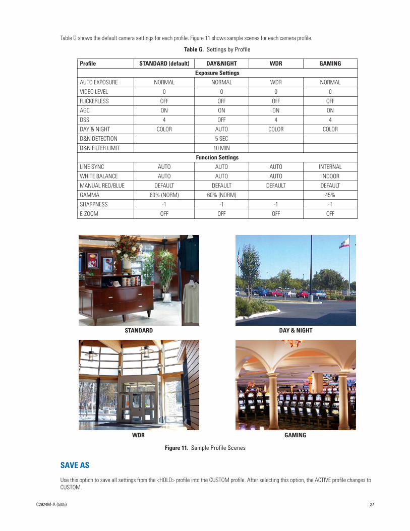
Table G shows the default camera settings for each profile. Figure 11 shows sample scenes for each camera profile.
Table G. Settings by Profile
Profile STANDARD (default) DAY&NIGHT WDR GAMING
Exposure Settings
AUTO EXPOSURE NORMAL NORMAL WDR NORMAL
VIDEO LEVEL 0 0 0 0
FLICKERLESS OFF OFF OFF OFF
AGC ON ON ON ON
DSS 4 OFF 4 4
DAY & NIGHT COLOR AUTO COLOR COLOR
D&N DETECTION 5 SEC
D&N FILTER LIMIT 10 MIN
Function Settings
LINE SYNC AUTO AUTO AUTO INTERNAL
WHITE BALANCE AUTO AUTO AUTO INDOOR
MANUAL RED/BLUE DEFAULT DEFAULT DEFAULT DEFAULT
GAMMA 60% (NORM) 60% (NORM) 45%
SHARPNESS -1 -1 -1 -1
E-ZOOM OFF OFF OFF OFF
C2924M-A (5/05) 27
Figure 11. Sample Profile Scenes
SAVE AS
Use this option to save all settings from the <HOLD> profile into the CUSTOM profile. After selecting this option, the ACTIVE profile changes to CUSTOM.
STANDARD DAY & NIGHT
WDR GAMING

EXPOSURE SETTINGSSelect this option to configure the exposure settings for the CCC1390H Series camera. The default EXPOSURE SETTINGS menu appears when AUTO EXPOSURE is set to NORMAL, BLC, or WDR. When AUTO EXPOSURE is set to MANUAL, the FLICKERLESS option is replaced with the SHUTTER SPEED option.
AUTO EXPOSURE
The automatic exposure feature automatically adjusts the electronic shutter and mechanical iris to set the correct exposure. Select one of the following automatic exposure modes:
NORMAL Select this mode to use the electronic shutter and mechanical iris to control exposure. As lighting conditions change, the camera adjusts exposure based on input from the electronic shutter.
BLC Select this mode for scenes that are strongly backlit. The camera corrects the image to bring out the detail of the subject, such as a person entering a building through a door.
MANUAL Select this mode to set the electronic shutter speed manually (refer to Shutter Speed for more information).
WDR Select this mode for scenes that include both high-light and low-light objects.
The default depends on the selected profile (refer to Table G.)
NOTES:
• You can also use the rear panel button to switch between NORMAL and WDR modes (refer to Quick Setup).
• When you select BLC, the VIDEO LEVEL option is disabled.
EXPOSURE SETTINGS
AUTO EXPOSURE > NORMALVIDEO LEVEL > 0FLICKERLESS > OFFAGC > ONDSS(SENS) > 4DAY & NIGHT > COLORD&N DETECTION >D&N FILTER LIMIT >BACK EXIT
EXPOSURE SETTINGS
AUTO EXPOSURE > MANUALVIDEO LEVEL > 0SHUTTER SPEED > 1/60AGC > ONDSS(SENS) > 4DAY & NIGHT > COLORD&N DETECTION >D&N FILTER LIMIT >BACK EXIT
NORMAL, BLC, or WDRAUTO EXPOSURE
MANUALAUTO EXPOSURE
28 C2924M-A (5/05)
• When you select MANUAL, the FLICKERLESS option changes to SHUTTER SPEED. Also, the DSS(SENS) option is disabled.
• When you select WDR, the GAMMA and E-ZOOM options are disabled.
VIDEO LEVEL
Use this option to set the video output voltage from 0.9 Vp-p to 1.1 Vp-p in increments of 0.02 Vp-p. Use it to compensate for signal loss due to long cable runs. You can also use it to boost the video output.
Select a value between -5 (0.9 Vp-p) and 5 (1.1 Vp-p). The default is 0 (1.0 Vp-p).
NOTE: When AUTO EXPOSURE is set to BLC, you cannot adjust the video level.
FLICKERLESS
In some installations, the cycle of the fluorescent lights may interfere with the electronic iris shutter speed. Use this option to override the shutter speed. When enabled, the shutter speed is set to 1/100 (NTSC) or 1/120 (PAL).
Select ON or OFF. The default is OFF.
NOTE: This option appears when AUTO EXPOSURE is set to NORMAL, BLC, or WDR.

SHUTTER SPEED
Use this option to set the shutter speed manually.
Select one of the following options: 1/60(NTSC), 1/50(PAL), 1/100(NTSC), 1/120(PAL), 1/250, 1/500, 1/1000, 1/2000, 1/4000, 1/10000, 1/20000, 1/50000. The default is 1/60(NTSC) or 1/50(PAL).
NOTE: This option appears when AUTO EXPOSURE is set to MANUAL.
AUTOMATIC GAIN CONTROL (AGC)
Automatic gain control (AGC) automatically adjusts the image when the light level changes. Most scenes benefit from AGC operation.
Select ON or OFF. The default is ON.
NOTE: You can also use the rear panel button to enable or disable AGC (refer to Quick Setup).
DIGITAL SLOW SHUTTER (DSS (SENS))
Digital slow shutter (DSS) slows the picture frame rate and increases the camera sensitivity under low-light conditions by increasing the number of fields of integration. Use this option to enable or disable this feature, and to set the number of integration fields.
Select one of the following options: OFF, 2, 4, 6, 8, 10, 20, 40. The default depends on the selected profile (refer to Table G.)
NOTES:
• If you disable SENS on the rear panel, the camera saves the DSS (SENS) value on the EXPOSURE SETTING menu (refer to Quick Setup).
• This option is automatically disabled when AUTO EXPOSURE is set to MANUAL.
• Depending on the number of fields of integration, the picture will develop a granular appearance and motion may lag, resulting in a stereo-scopic effect or streaking on fast-moving objects.
DAY AND NIGHT
Use this option to specify how the camera will switch between day (color) and night (black and white) operation.
Select one of the following options:
AUTO Select this option to switch the filter automatically as light conditions change. The D&N DETECTION and D&N FILTER LIMIT settings appear. EXPOSURE SETTINGS
C2924M-A (5/05) 29
The camera switches from day to night when the AGC gain level reaches 22 dB. It switches from night to day when the AGC gain level reaches 16 dB.
When AUTO is selected, both the angle of view and the lighting conditions may cause the camera filters to switch constantly. Use the D&N FILTER LIMIT to compensate for this (refer to Day and Night Filter Limit).
COLOR Select this option to operate the camera in day mode.
BW Select this option to operate the camera in night mode.
EXT. Select this option to use an external signal to switch between day and night modes (refer to Connecting External Control for more information). The D&N DETECTION and D&N FILTER LIMIT become enabled. In some installations, this option may be more reliable than AUTO mode.
The default is COLOR, except for the DAY&NIGHT profile, whose default is AUTO.
NOTES:
• You can also use the rear panel button to switch between AUTO and COLOR modes (refer to Quick Setup).
• When AGC is enabled, AUTO and EXT. modes are available. When AGC is disabled, AUTO and EXT. modes are not available; you can select only COLOR or BW mode.
AUTO EXPOSURE > NORMALVIDEO LEVEL > 0FLICKERLESS > OFFAGC > ONDSS(SENS) > 4DAY & NIGHT > COLORD&N DETECTION >D&N FILTER LIMIT >BACK EXIT

DAY AND NIGHT DETECTION
The camera regularly checks the brightness level. When the brightness level crosses the switch threshold and lasts longer than the D&N DETECTION setting, the camera switches the filter.
For example, the headlights of a passing car affect the brightness level in the camera, but not long enough for the filter to switch. The light of a cloudy day also affects the brightness level in the camera, long enough for the filter to switch.
Select one of the following options: 5 SEC, 30 SEC. The default is 5 SEC.
NOTE: This option is only enabled when the DAY & NIGHT option is set to AUTO or EXT.
DAY AND NIGHT FILTER LIMIT
In certain lighting conditions, the brightness level may cross the switch threshold quickly. As a result, the camera may constantly switch filters. Use this option to indicate how often to test the brightness level.
Select one of the following detection test intervals:
OFF Select this option to test the brightness level continuously, according to the D&N DETECTION setting (5 seconds or 30 seconds).
10 MIN Select this option to test the brightness level every 10 minutes.
30 MIN Select this option to test the brightness level every 30 minutes.
The default is 10 MIN when the DAY & NIGHT profile is selected. Otherwise, the default is OFF.
After the camera switches filters three times, and after the filter limit interval has passed, an asterisk (*) appears next to this setting. This indi-cates that the detection test has been performed.
NOTE: This option is only enabled when the DAY & NIGHT option is set to AUTO or EXT.
30 C2924M-A (5/05)
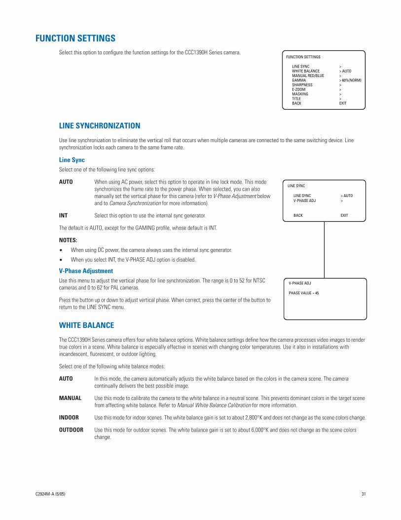
FUNCTION SETTINGSSelect this option to configure the function settings for the CCC1390H Series camera.
LINE SYNCHRONIZATION
Use line synchronization to eliminate the vertical roll that occurs when multiple cameras are connected to the same switching device. Line synchronization locks each camera to the same frame rate.
Line SyncSelect one of the following line sync options:
AUTO When using AC power, select this option to operate in line lock mode. This mode synchronizes the frame rate to the power phase. When selected, you can also manually set the vertical phase for this camera (refer to V-Phase Adjustment below and to Camera Synchronization for more information).
INT Select this option to use the internal sync generator.
The default is AUTO, except for the GAMING profile, whose default is INT.
NOTES:
• When using DC power, the camera always uses the internal sync generator.
• When you select INT, the V-PHASE ADJ option is disabled.
V-Phase AdjustmentUse this menu to adjust the vertical phase for line synchronization. The range is 0 to 52 for NTSC cameras and 0 to 62 for PAL cameras.
Press the button up or down to adjust vertical phase. When correct, press the center of the button to return to the LINE SYNC menu.
FUNCTION SETTINGS
LINE SYNC >WHITE BALANCE > AUTOMANUAL RED/BLUE >GAMMA > 60%(NORM)SHARPNESS >E-ZOOM >MASKING >TITLE >BACK EXIT
LINE SYNC
LINE SYNC > AUTOV-PHASE ADJ >
BACK EXIT
V-PHASE ADJ
PHASE VALUE = 45
C2924M-A (5/05) 31
WHITE BALANCE
The CCC1390H Series camera offers four white balance options. White balance settings define how the camera processes video images to render true colors in a scene. White balance is especially effective in scenes with changing color temperatures. Use it also in installations with incandescent, fluorescent, or outdoor lighting.
Select one of the following white balance modes:
AUTO In this mode, the camera automatically adjusts the white balance based on the colors in the camera scene. The camera continually delivers the best possible image.
MANUAL Use this mode to calibrate the camera to the white balance in a neutral scene. This prevents dominant colors in the target scene from affecting white balance. Refer to Manual White Balance Calibration for more information.
INDOOR Use this mode for indoor scenes. The white balance gain is set to about 2,800°K and does not change as the scene colors change.
OUTDOOR Use this mode for outdoor scenes. The white balance gain is set to about 6,000°K and does not change as the scene colors change.

MANUAL RED/BLUE
Select this option to display the MANUAL RED/BLUE menu.
Red GainUse this option to either increase or decrease the light level of the red elements in the camera image. Select a value between -5 and 5. The default is -1.
Blue GainUse this option to either increase or decrease the light level of the blue elements in the camera image. Select a value between -5 and 5. The default is -2.
Red HueUse this option to either increase or decrease the red hue in the camera image. Select a value between -5 and 5. The default is 1.
Blue HueUse this option to either increase or decrease the blue hue in the camera image. Select a value between -5 and 5. The default is 1.
GAMMA
Gamma correction adjusts the video signal to compensate for the nonlinear response of the monitor display.
Select one of the following options: 60%(NORM), 45%, or 100%. The default depends on the selected profile (refer to Table G).
NOTE: When AUTO EXPOSURE is set to WDR, you cannot change the gamma setting.
SHARPNESS
Select this option to display the SHARPNESS menu.
Aperture GainUse this option to increase or decrease the image sharpness, both vertically and horizontally. Select a value between -5 and 5. The default is -1.
E-ZOOM
Select this option to configure electronic zoom, including electronic panning.
MANUAL RED/BLUE
RED GAIN > -1BLUE GAIN > -2RED HUE > 1BLUE HUE > 1
BACK EXIT
SHARPNESS
APERTURE GAIN > -1
BACK EXIT
E-ZOOM
32 C2924M-A (5/05)
NOTE: When you enable electronic zoom, both the WDR auto exposure mode and masking are disabled. If either WDR or masking is active, electronic zoom is disabled.
ZoomSelect one of the following electronic zoom options: OFF, 1.5, 2.0, 2.5. The default is OFF.
PositionUse this option to pan and tilt the electronic zoom frame to a specific portion of the scene.
To position the electronic zoom frame:
1. Change the ZOOM setting on the E-ZOOM menu to 1.5. Positioning is possible only at 1.5 zoom.
2. Select the POSITION menu. The POSITION menu appears.
3. Press the button up, down, left, or right to position the frame. When correct, press the center of the button to return to the E-ZOOM menu.
4. To use 2.0 or 2.5 zoom, change the ZOOM setting to the desired value.
ZOOM > OFFPOSITION >
BACK EXIT
POSITION
MASKING
Masking lets you block out certain areas of a camera scene. Select this option to configure one to eight masks in the camera image.
NOTE: When you enable masking, electronic zoom is disabled. If electronic zoom is active, masking is disabled.
MaskUse this option to enable or disable masking. The default is OFF.
Mask EditUse this option to configure one or more masks. There is no default mask.
To edit a mask:
1. Change the MASK setting on the MASKING menu to ON.
2. Select the MASK EDIT menu. The MASK SETTING menu appears.
3. Use the pointer to configure the mask area.
a. Press the button up, down, left, or right to move the cursor to the upper left corner of the mask.
b. Press the center of the button to mark the upper left corner.
c. Press the button up, down, left, or right to move the cursor to the lower right corner of the mask.
NOTE: If you move the cursor either left or above the start point, the mask edit is cancelled.
d. Press the center of the button to mark the lower right corner. The mask area is blacked out. The MASKING menu appears with the new mask.
4. Repeat step 3 for each additional mask.
If you add a ninth mask, the camera erases the first mask. You cannot configure more than eight masks.
Mask EraseSelect this option to erase one or more masks. The camera erases masks from the last created to the first created.
MASKING
MASK > OFFMASK EDIT >MASK ERASE
BACK EXIT
MASK SETTING
C2924M-A (5/05) 33
To erase a mask, select MASK ERASE. The mask that was last created disappears. Repeat to erase additional masks.
TITLE
Select this option to configure the camera title.
TitleUse this option to enable or disable the title display. The default is OFF.
Title EditUse this option to enter or edit the camera title, up to 16 characters. The default is blank.
To enter a camera title:
1. Change the TITLE setting on the TITLE menu to ON.
2. Select the EDIT TITLE menu. The EDIT TITLE menu appears.
3. Press the button up, down, left, or right to move the cursor to the desired character.
The space character is located below the letter n.
4. Press the center of the button to select the character. The selected character appears in the blank area at the bottom of the screen.
TITLE
TITLE > OFFEDIT TITLE >
BACK EXIT
EDIT TITLE
ABCDEFGHIJKLMNOPQRSTUVWXYZabcdefghijklmnopqrstuvwxyz 0123456789-/
BACK BS
_________________

5. To clear a character, select BS (backspace). The camera deletes the last character entered.
6. Repeat steps 3 and 4 until you have entered the camera title.
7. When the title is correct, select BACK to return to the TITLE menu.
CAMERA SETUPSelect this option to configure the serial communication and rear panel function settings for the CCC1390H Series camera. Refer to Connecting External Control for information on wiring the serial interface.
AddressThe CCC1390H Series camera can be accessed remotely from selected Pelco controllers. Use this option to assign a receiver address to the camera. This address identifies the camera on the serial chain. Select a value from 1 to 30. The default is 1.
NOTES:
• Each camera must have a unique address.
• Be sure to assign the address before accessing the camera remotely.
COM SpeedUse this option to set the communication or baud rate for this camera. This must match the setting for the other cameras and controllers on the serial chain. Select one of the following: 2400, 4800, 9600, 19200. The default is 4800.
LEDSelect this option to enable or disable the rear panel indicators. The default is ON.
SwitchSelect this option to enable or disable quick setup on the rear panel (refer to Quick Setup). The default is ON.
AUTO IRIS LENS ADJUSTMENTSelect this option to adjust the electronic properties of the auto iris lens to the auto iris electronic properties of the camera. Perform this procedure before using the camera or each time you change the lens.
CAMERA SETUP
ADDRESS > 1COM SPEED > 4800LED > ONSWITCH > ON
BACK EXIT
AI AUTO ADJUSTMENT
OK CANCEL
34 C2924M-A (5/05)
To perform this procedure:
1. Mount the auto iris lens to the camera (refer to Lens Mounting).
2. Aim the camera at a bright, flickerless scene.
3. Select AI AUTO ADJUSTMENT. The AI AUTO ADJUSTMENT menu appears.
4. Select OK. The camera performs the procedure. Then the MAIN MENU appears.
PIXEL CORRECTIONIf white spots appear in the video image, one or more pixels on the camera imager may be defective. This condition is common to CCD camera imagers.
Select this option to automatically detect and correct these defects. This feature helps you maintain image quality.
To perform this procedure:
1. Use a lens cap to cover the lens. Make sure no light can enter the lens.
NOTE: The mechanical iris lens aperture does not completely block the light. Therefore, you should use a lens cap.
2. Select PIXEL CORRECTION. The PIXEL CORRECTION menu appears.
3. Select OK. The camera performs the procedure. Then the MAIN MENU appears.
NOTES:
• Any defective pixels that cannot be completely corrected may still appear.
• Defective pixels may reappear when DSS(SENS) is enabled.
SYSTEM INFORMATIONSelect this option to display the camera firmware information.
Restore Factory SettingsSelect this option to reset the camera to the factory default settings. This option clears all saved user-definable settings, except the following:
• CAMERA SETUP menu: ADDRESS, COM SPEED
• LINE SYNC menu: V-PHASE ADJ
• PIXEL CORRECTION
To restore factory default settings:
1. Select RESTORE FACTORY SETTINGS on the SYSTEM INFORMATION menu. The RESTORE FACTORY SETTINGS menu appears.
2. Select OK. The camera resets all parameters to the factory default settings, except those listed above. Then the MAIN MENU appears.
PIXEL CORRECTION
COVER THE LENSAND SELECT OK
OK CANCEL
SYSTEM INFORMATION
FIRMWARE VERSION 1.0OSD VERSION 1.0
RESTORE FACTORY SETTINGS >
BACK EXIT
RESTORE FACTORY SETTINGS
OK CANCEL
C2924M-A (5/05) 35
Lens FocusingAfter mounting the lens, you must focus your CCC1390H Series camera. You will adjust both the back focus (on the camera) and the fine focus (on the lens).
NOTE: The back focus has already been adjusted using a standard CS-mount lens. However, you might need to adjust it again to match the mounted lens.
1. Auto iris only: Cover the auto iris lens with a suitable neutral density (ND) filter. This opens the iris fully. For best results, use an ND3 filter.
2. Manual iris only: Open the iris completely. Refer to Figure 12, which shows the manual iris, varifocal, and lens focus locking screws for a sample lens. Refer to your lens documentation for more information.
Figure 12. Lens Focus
3. If necessary, enable Automatic Gain Control (AGC) on the EXPOSURE SETTINGS menu.
1.5 MMALLENWRENCH
VARIFOCALLOCKINGSCREW
LENS FOCUSLOCKING SCREW
MANUAL IRISLOCKING SCREW
MAIN MENU
36 C2924M-A (5/05)
AGC is enabled by default.
a. Display the EXPOSURE SETTINGS menu.
b. Change AGC to ON.
c. Select EXIT to save the AGC setting.
4. Aim the camera at the farthest object in the field of view. Make sure it is at least 6.5 ft (2 m) away.
5. Fixed focal length lens only:
a. Set the lens focal length to far (∞).
b. Adjust the back focus:
(1) Use a 1.5-mm Allen wrench to loosen the back focus locking screw.
(2) Turn the lens until the image is focused.
(3) Tighten the back focus locking screw clockwise.
Back focus is a coarse adjustment. You will make the fine focus adjustment in the next step.
c. Adjust the lens focus to achieve the best fine focus.
WARNING: Do not over-tighten the back focus locking screw because you may damage the camera.
PROFILES >EXPOSURE SETTINGS >FUNCTION SETTINGS >CAMERA SETUP >AI AUTO ADJUSTMENT >PIXEL CORRECTION >SYSTEM INFORMATION >
EXIT
EXPOSURE SETTINGS
AUTO EXPOSURE > NORMALVIDEO LEVEL > 0FLICKERLESS > OFFAGC > ONDSS(SENS) > 4DAY & NIGHT > COLORD&N DETECTION >D&N FILTER LIMIT >BACK EXIT
6. Varifocal lens only:
a. Set the varifocal to wide (W) and the lens focal length to far (∞).
b. Adjust the back focus:
(1) Use a 1.5-mm Allen wrench to loosen the back focus locking screw.
(2) Turn the lens until the image is focused.
(3) Tighten the back focus locking screw clockwise.
Back focus is a coarse adjustment. You will make the fine focus adjustment in steps c and d.
c. Move the varifocal locking screw up or down to set the field of view.
d. Adjust the lens focus to achieve the best fine focus.
e. Repeat steps c and d until the focus is correct.
7. Manual iris only: Adjust the iris for the best picture quality. The largest aperture gives the best light sensitivity; the smallest aperture gives the greatest depth of field.
8. Tighten all lens locking screws.
NOTE: When tightening the lens locking screws, do not over-turn or force any screw.
9. Auto iris only: Remove the ND filter.
10. If necessary, disable AGC.
a. Display the EXPOSURE SETTINGS menu.
b. Change AGC to OFF.
c. Select EXIT to save the AGC setting.
11. Auto iris only: Perform the auto iris lens adjustment procedure (refer to Auto Iris Lens Adjustment).
12. As soon as you finish customizing this and all other camera settings, save your custom settings into the CUSTOM profile. This protects them in case the camera loses power
WARNING: Do not over-tighten the back focus locking screw because you may damage the camera.
MAIN MENU
PROFILES >EXPOSURE SETTINGS >FUNCTION SETTINGS >CAMERA SETUP >AI AUTO ADJUSTMENT >PIXEL CORRECTION >SYSTEM INFORMATION >
EXIT
EXPOSURE SETTINGS
AUTO EXPOSURE > NORMALVIDEO LEVEL > 0FLICKERLESS > OFFAGC > OFFDSS(SENS) > 4DAY & NIGHT > COLORD&N DETECTION >D&N FILTER LIMIT >BACK EXIT
C2924M-A (5/05) 37
or must be restarted (refer to Profiles for more information).

Camera SynchronizationCamera synchronization may affect installations that use two or more AC power supplies for multiple cameras. Due to different power phases, a brief vertical roll may appear on the monitor when switching between cameras. To eliminate this vertical roll, adjust the phase control to synchronize the cameras to one another.
It may be necessary for two people to communicate when synchronizing cameras, one at the camera and the other at the monitor, to observe the vertical roll and the effect of any camera adjustments.
To synchronize cameras:
1. Choose a reference camera to which all other cameras will be phased.
2. Access V-PHASE ADJ menu for a camera. Press the button up and down to adjust the vertical phase until the camera is synchronized to the reference camera.
A dual trace oscilloscope is recommended, but not required, to adjust camera phase. Align the vertical sync pulses of the reference camera to the selected camera.
3. After each adjustment, switch back and forth between the adjusted camera and the reference camera. Repeat this process until the roll between the cameras disappears completely.
4. Adjust the phase of all other cameras by repeating steps 2 and 3. Always adjust to the reference camera selected in step 1.
5. As soon as you finish customizing this and all other camera settings, save your custom settings into the CUSTOM profile. This protects them in case the camera loses power or must be restarted (refer to Profiles for more information).
To adjust phase control:
1. Select LINE SYNC on the FUNCTION SETTINGS menu. The LINE SYNC menu appears.
2. Switch the LINE SYNC setting to AUTO.
3. Select V-PHASE ADJ. The V-PHASE ADJ menu appears.
4. Press the button up or down to change the PHASE VALUE. On the CCC1390H-6 (NTSC) camera, the range is 0 to 52. On the CCC1390H-6X (PAL) camera, the range is 0 to 62.
5. Press the center of the button to return to the LINE SYNC menu.
MAIN MENU
PROFILES >EXPOSURE SETTINGS >FUNCTION SETTINGS >CAMERA SETUP >AI AUTO ADJUSTMENT >PIXEL CORRECTION >SYSTEM INFORMATION >
EXIT
FUNCTION SETTINGS
LINE SYNC >WHITE BALANCE > AUTOMANUAL RED/BLUE >GAMMA > 60%(NORM)SHARPNESS >E-ZOOM >MASKING >TITLE >BACK EXIT
LINE SYNC
LINE SYNC > AUTOV-PHASE ADJ >
BACK EXIT
V-PHASE ADJ
PHASE VALUE = 45
38 C2924M-A (5/05)
6. Select EXIT to close the setup menus.
7. As soon as you finish customizing this and all other camera settings, save your custom settings into the CUSTOM profile. This protects them in case the camera loses power or must be restarted (refer to Profiles for more information).

Manual White Balance CalibrationIn some installations, use manual white balance to render the most accurate image color possible. Mixed color applications may affect the amount of color adjustment. For example, a small white object on a large blue surface may have a reddish tint. Manual white balance uses a calibration image to identify the correct white level. The camera then uses this white level when adjusting overall image color.
NOTE: Manual white balance is recommended only for indoor applications that have a single primary light source.
Example: A CCC1390H camera is installed in a pan/tilt enclosure in a clothing store in a shopping mall. Mixed colors are located throughout the store. Overhead lights provide the primary illumination, but some light also enters the store from the mall. As the camera pans a section filled with blue clothing, the camera may redden the image to compensate for the blue. When properly calibrated, the camera will not try to adjust scenes with predominant amounts of red or blue.
To calibrate the manual white balance:
1. Focus the camera on a neutral color scene. Select a neutral scene with the following characteristics:
• Little or no black
• Not predominantly red
• Not predominantly blue
• No direct light source, such as a lamp or a window
2. Select WHITE BALANCE on the FUNCTION SETTINGS menu.
3. Select AUTO. This calibrates the white balance gain to the neutral scene.
4. Change WHITE BALANCE from AUTO to MANUAL. This locks the white balance gain into camera memory.
NOTE: If you change WHITE BALANCE from MANUAL to a different mode, the stored manual white balance settings are erased. You will have to perform this procedure again.
5. Select EXIT to close the setup menus.
6. Focus the camera on the target scene.
7. As soon as you finish customizing this and all other camera settings, save your custom settings into the CUSTOM profile. This protects them in case the camera loses power or must be restarted (refer to Profiles for more information).
MAIN MENU
PROFILES >EXPOSURE SETTINGS >FUNCTION SETTINGS >CAMERA SETUP >AI AUTO ADJUSTMENT >PIXEL CORRECTION >SYSTEM INFORMATION >
EXIT
FUNCTION SETTINGS
LINE SYNC >WHITE BALANCE > AUTOMANUAL RED/BLUE >GAMMA > 60%(NORM)SHARPNESS >E-ZOOM >MASKING >TITLE >BACK EXIT
C2924M-A (5/05) 39

Specifications
GENERALDay/Night Operation
Day Infrared (IR) cut filterNight BK-7 glass, same optical displacement as day
Imaging Device 1/3-inch image format Sony SS-2WD CCD
Dynamic Range 60 dB maximum (WDR mode)
Picture ElementsNTSC 768 (H) x 494 (V) (approx. 380K)PAL 752 (H) x 582 (V) (approx. 440K)
Sensing Area 6 mm diagonal
Scanning System 525 (NTSC)/625 (PAL), 2:1 interlace
Synchronization AC line lock/internal
Horizontal Resolution 530 TV lines (B-W); 480 TV lines (color)
Electronic Shutter RangeNTSC 1/60-1/50,000 secondPAL 1/50-1/50,000 second
Auto Iris Lens Type DC-drive (autosensing)
Minimum IlluminationB-W (SENS 40x) 0.002 lux, F1.2, 40 IRE, AGC on, 75% scene reflectanceColor (SENS 40x) 0.02 lux, F1.2, 40 IRE, AGC on, 75% scene reflectanceB-W 0.08 lux, F1.2, 40 IRE, AGC on, 75% scene reflectanceColor 0.8 lux, F1.2, 40 IRE, AGC on, 75% scene reflectance
Filter Switching ThresholdDay to Night 1.6 lux, average scene illuminationNight to Day 1.9 lux, average scene illumination
B-W COLOR
DARK LIGHT
1.6 LUX22 DB
1.9 LUX16 DB
AVERAGE SCENE ILLUMINANCE
AVERAGE AGC GAIN
HYSTERESIS
40 C2924M-A (5/05)
Digital Slow Shutter (SENS) Selectable: on/off; 2x, 4x, 6x, 8x, 10x, 20x, 40x
Electronic PTZ Selectable: 1.5x, 2.0x, 2.5x
Signal-to-Noise Ratio >50 dB
Vertical Phase Adjustable ±90˚
Automatic Gain Control Selectable: on/off
Backlight Compensation Selectable: on/off
Flickerless Mode Selectable: on/off; 1/100 sec (NTSC), 1/120 sec (PAL)
Auto White Balance Selectable: on/off, 4 modes
Day/Night Selectable: on/off, 4 modes
Signal Processing Digital signal processing (DSP)
Video Output 1 Vp-p, 75 ohms
Gamma Correction Selectable: on/off, 0.45, 0.6, 1.0
White Balance Range 2,500° to 8,600°K

ELECTRICALPower Requirements
CCC1390H-6 24 VAC ±15%/12 VDC ±15%, 60 HzCCC1390H-6X 24 VAC ±15%/12 VDC ±15%, 50 Hz
Power Consumption 3.5 watts
Power Connector 3-pin terminal strip, push-in type
Video Connector BNC
Auto Iris Connector 4-pin connector (miniature square)
Mode Indicators 4 LED
Controls 5-position buttonSerial data termination switch
Control Connector 7-pin micro (1.25 mm) connectorData I/O (Pelco P or Pelco D protocol)External day/night filter control
MECHANICALLens Mount CS mount
Camera Mount 1/4-inch UNC-20 screw, top or bottom of camera housing
ENVIRONMENTALOperating Temperature 14° to 122°F (-10° to 50°C)
Storage Temperature -4° to 140°F (-20° to 60°C)
Operating Humidity 20% to 80% (noncondensing)
Storage Humidity 20% to 90% (noncondensing)
PHYSICALDimensions 2.69” D x 2.09” W x 2.19” H
(6.83 x 5.31 x 5.56 cm)
Weight (without lens) 0.44 lb (0.20 kg)
Shipping Weight 1 lb (0.45 kg)
C2924M-A (5/05) 41
(Design and product specifications subject to change without notice.)


PRODUCT WARRANTY AND RETURN INFORMATION
WARRANTYPelco will repair or replace, without charge, any merchandise proved defective in material orworkmanship for a period of one year after the date of shipment.
Exceptions to this warranty are as noted below:
• Five years on FT/FR8000 Series fiber optic products.
• Three years on Genex® Series products (multiplexers, server, and keyboard).
• Three years on Camclosure® and fixed camera models, except the CC3701H-2,CC3701H-2X, CC3751H-2, CC3651H-2X, MC3651H-2, and MC3651H-2X camera models,which have a five-year warranty.
• Two years on standard motorized or fixed focal length lenses.
• Two years on Legacy®, CM6700/CM6800/CM9700 Series matrix, and DF5/DF8 Seriesfixed dome products.
• Two years on Spectra®, Esprit®, ExSite™, and PS20 scanners, including when used incontinuous motion applications.
• Two years on Esprit® and WW5700 Series window wiper (excluding wiper blades).
• Eighteen months on DX Series digital video recorders, NVR300 Series network videorecorders, and Endura™ Series distributed network-based video products.
• One year (except video heads) on video cassette recorders (VCRs). Video heads will becovered for a period of six months.
• Six months on all pan and tilts, scanners or preset lenses used in continuous motionapplications (that is, preset scan, tour and auto scan modes).
Pelco will warrant all replacement parts and repairs for 90 days from the date of Pelcoshipment. All goods requiring warranty repair shall be sent freight prepaid to Pelco, Clovis,California. Repairs made necessary by reason of misuse, alteration, normal wear, or accidentare not covered under this warranty.
Pelco assumes no risk and shall be subject to no liability for damages or loss resulting fromthe specific use or application made of the Products. Pelco’s liability for any claim, whetherbased on breach of contract, negligence, infringement of any rights of any party or productliability, relating to the Products shall not exceed the price paid by the Dealer to Pelco forsuch Products. In no event will Pelco be liable for any special, incidental or consequentialdamages (including loss of use, loss of profit and claims of third parties) however caused,whether by the negligence of Pelco or otherwise.
The above warranty provides the Dealer with specific legal rights. The Dealer may also haveadditional rights, which are subject to variation from state to state.
If a warranty repair is required, the Dealer must contact Pelco at (800) 289-9100 or(559) 292-1981 to obtain a Repair Authorization number (RA), and provide the followinginformation:1. Model and serial number2. Date of shipment, P.O. number, Sales Order number, or Pelco invoice number3. Details of the defect or problem
If there is a dispute regarding the warranty of a product which does not fall under thewarranty conditions stated above, please include a written explanation with the productwhen returned.
Method of return shipment shall be the same or equal to the method by which the item wasreceived by Pelco.
RETURNSIn order to expedite parts returned to the factory for repair or credit, please call the factory at(800) 289-9100 or (559) 292-1981 to obtain an authorization number (CA number if returnedfor credit, and RA number if returned for repair).
All merchandise returned for credit may be subject to a 20% restocking and refurbishingcharge.
Goods returned for repair or credit should be clearly identified with the assigned CA or RAnumber and freight should be prepaid. Ship to the appropriate address below.
If you are located within the continental U.S., Alaska, Hawaii or Puerto Rico, send goods to:Service DepartmentPelco3500 Pelco WayClovis, CA 93612-5699
If you are located outside the continental U.S., Alaska, Hawaii or Puerto Rico and areinstructed to return goods to the USA, you may do one of the following:
If the goods are to be sent by a COURIER SERVICE, send the goods to:Pelco3500 Pelco WayClovis, CA 93612-5699 USA
If the goods are to be sent by a FREIGHT FORWARDER, send the goods to:Pelco c/o Expeditors473 Eccles AvenueSouth San Francisco, CA 94080 USAPhone: 650-737-1700Fax: 650-737-0933
REVISION HISTORY
Manual # Date CommentsC2924M 4/05 Original version.C2924M-A 5/05 Updated wiring distances table and specifications.
Pelco, the Pelco logo, Spectra, Genex, Legacy, Esprit, DomePak, ImagePak, and Camclosure are registered trademarks of Pelco. ©Copyright 2005, Pelco. All rights reserved.PelcoNet, Endura, and ExSite are trademarks of Pelco.

Worldwide Headquarters3500 Pelco Way
Clovis, California 93612 USA
USA & CanadaTel: 800/289-9100Fax: 800/289-9150
InternationalTel: 1-559/292-1981Fax: 1-559/348-1120
www.pelco.com
ISO9001
United States | Canada | United Kingdom | The Netherlands | Singapore | Spain | Scandinavia | France | Middle East