ccb network interface - caltech astronomymcs/gbt/ccb_network_interface.pdf · abstract this...
TRANSCRIPT

The network interfaces of the CCB server
[Document number: A48001N002, revision 13]
Martin ShepherdCalifornia Institute of Technology
December 29, 2005

This page intentionally left blank.

Abstract
This document describes the network interfaces that the CCB server presents to remote CCBclient programs, such as the CCB manager, dump-mode display programs, and standalonediagnostic programs. These interfaces are presented in the form of public APIs, by a suiteof shared libraries.

Contents
1 Introduction 10
1.1 Points of interest to writers of the CCB Manager program . . . . . . . . . . 11
1.2 Points of interest to writers of the CCB server program . . . . . . . . . . . . 12
1.3 The organization of this manual . . . . . . . . . . . . . . . . . . . . . . . . . 12
1.4 The three TCP/IP links opened by the CCB server . . . . . . . . . . . . . . 13
1.5 Connection establishment . . . . . . . . . . . . . . . . . . . . . . . . . . . . 13
1.6 Connection authentication . . . . . . . . . . . . . . . . . . . . . . . . . . . . 14
1.7 Initial configuration . . . . . . . . . . . . . . . . . . . . . . . . . . . . . . . . 14
1.8 Single threaded versus multi-threaded . . . . . . . . . . . . . . . . . . . . . . 14
1.9 Library usage caveats . . . . . . . . . . . . . . . . . . . . . . . . . . . . . . . 16
1.10 Shared libraries and their versioning . . . . . . . . . . . . . . . . . . . . . . . 17
2 Installation 18
2.1 Getting the source code . . . . . . . . . . . . . . . . . . . . . . . . . . . . . 18
2.2 The basics of installation . . . . . . . . . . . . . . . . . . . . . . . . . . . . . 18
2.3 Compiling in a different directory . . . . . . . . . . . . . . . . . . . . . . . . 19
2.4 Specifying where files are installed . . . . . . . . . . . . . . . . . . . . . . . . 20
2.5 Generating this manual and other CCB documentation . . . . . . . . . . . . 20
2.6 Testing the libraries using the demonstration programs . . . . . . . . . . . . 22
2.6.1 ccb dummy client . . . . . . . . . . . . . . . . . . . . . . . . . . . . . 24
2.7 Run-time configuration files . . . . . . . . . . . . . . . . . . . . . . . . . . . 24
2.8 The ccb authorized ips configuration file . . . . . . . . . . . . . . . . . . . . 24
2.9 The assignment of log IDs . . . . . . . . . . . . . . . . . . . . . . . . . . . . 25
3 The common parts of the CCB server and client APIs 27
3.1 The configuration of the CCB . . . . . . . . . . . . . . . . . . . . . . . . . . 27
2

3.1.1 The configuration of the phase switches . . . . . . . . . . . . . . . . . 29
3.1.2 The configuration of the calibration diodes . . . . . . . . . . . . . . . 32
3.1.3 The configuration of hardware timing parameters . . . . . . . . . . . 34
3.1.4 The configuration of sampler control parameters . . . . . . . . . . . . 38
3.2 Textual configuration . . . . . . . . . . . . . . . . . . . . . . . . . . . . . . . 39
3.2.1 ccb parse CCBConfig() . . . . . . . . . . . . . . . . . . . . . . . . . . 41
3.2.2 ccb read CCBConfig() . . . . . . . . . . . . . . . . . . . . . . . . . . 41
3.2.3 ccb print CCBConfig() . . . . . . . . . . . . . . . . . . . . . . . . . . 42
3.2.4 ccb write CCBConfig() . . . . . . . . . . . . . . . . . . . . . . . . . . 42
3.2.5 Parsing and displaying phase-switch specifications . . . . . . . . . . . 43
ccb parse CCBPhaseSwitches() . . . . . . . . . . . . . . . . . . . 43
ccb render CCBPhaseSwitches() . . . . . . . . . . . . . . . . . . 43
3.2.6 Parsing and displaying cal-diode specifications . . . . . . . . . . . . . 44
ccb parse CCBCalDiodes() . . . . . . . . . . . . . . . . . . . . . 44
ccb render CCBCalDiodes() . . . . . . . . . . . . . . . . . . . . 44
3.3 Integration and scan timing information . . . . . . . . . . . . . . . . . . . . 45
3.3.1 Interval computations . . . . . . . . . . . . . . . . . . . . . . . . . . 46
ccb scale interval() . . . . . . . . . . . . . . . . . . . . . . . . . 46
ccb add intervals() . . . . . . . . . . . . . . . . . . . . . . . . . 47
ccb subtract interval() . . . . . . . . . . . . . . . . . . . . . . . 47
ccb compare intervals() . . . . . . . . . . . . . . . . . . . . . . 47
ccb zero interval() . . . . . . . . . . . . . . . . . . . . . . . . . 48
ccb interval is zero() . . . . . . . . . . . . . . . . . . . . . . . . 48
ccb clock interval() . . . . . . . . . . . . . . . . . . . . . . . . . 48
3.3.2 Cal-diode and phase-switch settling times . . . . . . . . . . . . . . . 48
3.3.3 The number of phase-switch states per cycle . . . . . . . . . . . . . . 49
3.3.4 The physical duration of an integration period . . . . . . . . . . . . . 50
3.3.5 The effective integration time . . . . . . . . . . . . . . . . . . . . . . 50
3.3.6 The duration of a scan . . . . . . . . . . . . . . . . . . . . . . . . . . 50
3.3.7 The number of integrations that fit within a time interval . . . . . . . 51
3.3.8 The number of integrations in a calibration cycle . . . . . . . . . . . 51
3.4 Timestamps . . . . . . . . . . . . . . . . . . . . . . . . . . . . . . . . . . . . 52
3.4.1 Zero-initializing a timestamp . . . . . . . . . . . . . . . . . . . . . . . 53
3

3.4.2 Getting the current date and time . . . . . . . . . . . . . . . . . . . . 53
3.4.3 Comparing two timestamps . . . . . . . . . . . . . . . . . . . . . . . 53
3.4.4 Computing the amount of time remaining until a given time . . . . . 53
3.4.5 Adding a time-interval to a timestamp . . . . . . . . . . . . . . . . . 54
3.4.6 Converting a time t value to a CCBTimeStamp value . . . . . . . . . 54
3.4.7 Converting a CCBTimeStamp value to a time t value . . . . . . . . . 54
3.4.8 Getting the clock-time from a timestamp . . . . . . . . . . . . . . . . 55
3.5 Pseudo-random fake samples . . . . . . . . . . . . . . . . . . . . . . . . . . . 55
3.5.1 The values of integrated fake samples . . . . . . . . . . . . . . . . . . 55
3.5.2 The values of fake samples . . . . . . . . . . . . . . . . . . . . . . . . 56
3.6 Physical status-monitoring and the front-panel LEDs . . . . . . . . . . . . . 58
3.6.1 Monitor data calibration . . . . . . . . . . . . . . . . . . . . . . . . . 59
3.6.2 Computing the states of the front-panel status LEDs . . . . . . . . . 60
3.6.3 Computing the states of the front-panel mode LEDs . . . . . . . . . . 61
4 The CCB manager communications API 63
4.1 Include files . . . . . . . . . . . . . . . . . . . . . . . . . . . . . . . . . . . . 65
4.2 The CCB-client communications library . . . . . . . . . . . . . . . . . . . . 66
4.3 Creating the client resources needed to talk to a CCB server . . . . . . . . . 66
4.4 Connecting to a CCB server . . . . . . . . . . . . . . . . . . . . . . . . . . . 67
4.5 Disconnecting from a CCB server . . . . . . . . . . . . . . . . . . . . . . . . 68
4.6 Deleting a redundant CCBClientLink object . . . . . . . . . . . . . . . . . . 68
4.7 Requesting non-blocking I/O . . . . . . . . . . . . . . . . . . . . . . . . . . . 69
4.8 ccb client communicate() – Perform client socket I/O . . . . . . . . . . . . . 69
4.9 Client I/O multiplexing . . . . . . . . . . . . . . . . . . . . . . . . . . . . . . 70
4.9.1 Using the select() system call . . . . . . . . . . . . . . . . . . . . . . 70
4.9.2 Using the poll() system call . . . . . . . . . . . . . . . . . . . . . . . 71
4.9.3 Third party event handlers . . . . . . . . . . . . . . . . . . . . . . . . 72
4.9.4 Using threads to multiplex I/O . . . . . . . . . . . . . . . . . . . . . 73
4.10 Registering a command-error callback function . . . . . . . . . . . . . . . . . 73
4.11 Outgoing CCB commands . . . . . . . . . . . . . . . . . . . . . . . . . . . . 75
4.11.1 Outgoing CCB control commands . . . . . . . . . . . . . . . . . . . . 75
ccb queue start scan cmd() – Queuing a start-scan command . . . . 76
ccb queue stop scan cmd() – Queuing a stop-scan command . . . . 77
4

ccb queue dump scan cmd() – Queuing a dump-scan command . . . 78
ccb queue load driver cmd() – Queuing a load-driver command . . . 80
ccb queue monitor cmd() – Queuing a monitor command . . . . . . 80
ccb queue telemetry cmd() – Queuing a telemetry command . . . . 80
ccb queue logger cmd() – Queuing a logger command . . . . . . . . 81
ccb queue reset cmd() – Queuing a reset command . . . . . . . . . 81
ccb queue ping cmd() – Queuing a ping command . . . . . . . . . 82
ccb queue status request cmd() – Queuing a status-request command 83
ccb queue shutdown cmd() – Queuing a shutdown command . . . . 83
ccb queue reboot cmd() – Queuing a reboot command . . . . . . . 83
ccb queue set dacs cmd() – Queuing a set-dacs command . . . . . . 84
4.12 Incoming control-link replies . . . . . . . . . . . . . . . . . . . . . . . . . . . 86
ccb status reply callback() – Routing status-request replies . . . . . . . . . 86
4.13 Incoming telemetry messages . . . . . . . . . . . . . . . . . . . . . . . . . . . 87
ccb monitor msg callback() – Routing telemetry monitor-data messages . . 89
ccb integ msg callback() – Routing telemetry integ-data messages . . . . . 90
ccb log msg callback() – Routing telemetry log-message messages . . . . . 93
4.14 A TCL wrapper around the CCB client API . . . . . . . . . . . . . . . . . . 94
5 The CCB server communications API 103
5.1 Include files . . . . . . . . . . . . . . . . . . . . . . . . . . . . . . . . . . . . 103
5.2 The CCB-server communications library . . . . . . . . . . . . . . . . . . . . 104
5.3 Creating the resources used to communicate with CCB managers . . . . . . 104
5.3.1 The CCB server’s device-driver interface . . . . . . . . . . . . . . . . 105
5.4 Shutting down server communications . . . . . . . . . . . . . . . . . . . . . . 111
5.5 Server I/O multiplexing . . . . . . . . . . . . . . . . . . . . . . . . . . . . . 112
5.6 Queuing replies to control commands . . . . . . . . . . . . . . . . . . . . . . 112
5.7 Queuing outgoing telemetry messages . . . . . . . . . . . . . . . . . . . . . . 112
5.7.1 Queuing outgoing monitor-data messages . . . . . . . . . . . . . . . . 113
5.7.2 Queuing outgoing integ-data messages . . . . . . . . . . . . . . . . . 113
ccb zero integ frame() . . . . . . . . . . . . . . . . . . . . . . 114
5.7.3 Queuing outgoing dump-frame messages . . . . . . . . . . . . . . . . 114
ccb zero dump frame() . . . . . . . . . . . . . . . . . . . . . . 115
ccb phase switch sequence() . . . . . . . . . . . . . . . . . . . 115
5
5.7.4 Queuing outgoing log-message messages . . . . . . . . . . . . . . . . 116
6 Library internals 117
6.1 The message translation layer . . . . . . . . . . . . . . . . . . . . . . . . . . 119
6.1.1 Message structure specification . . . . . . . . . . . . . . . . . . . . . 119
6.1.2 Supported data-types within message structures . . . . . . . . . . . . 119
6.1.3 CCBNetMsg - The base-class of all messages . . . . . . . . . . . . . . 119
6.1.4 Some example message structures . . . . . . . . . . . . . . . . . . . . 120
6.1.5 CCBNetMsgMember – Message field descriptions . . . . . . . . . . . 120
6.1.6 CCBNetMsgInfo – Individual message descriptions . . . . . . . . . . 121
6.2 The CCB interface layer . . . . . . . . . . . . . . . . . . . . . . . . . . . . . 122
6.2.1 The message structures of outgoing control messages . . . . . . . . . 123
CCBPhaseSwitchCmd – The phase-switching configuration command 124
CCBCalDiodeCmd – The calibration diode configuration command 125
CCBTimingCmd – The acquisition-timing configuration command 125
CCBSamplerCmd – The sampler configuration command . . . . . 125
CCBStartScanCmd – The start-scan command . . . . . . . . . . 126
CCBStopScanCmd – The stop-scan command . . . . . . . . . . 126
CCBDumpScanCmd – The dump-scan command . . . . . . . . . 126
CCBMonitorCmd – The monitor command . . . . . . . . . . . . 127
CCBTelemetryCmd – The telemetry command . . . . . . . . . . 127
CCBLoggerCmd – The logger command . . . . . . . . . . . . . 127
CCBResetCmd – The reset command . . . . . . . . . . . . . . 127
CCBPingCmd – The ping command . . . . . . . . . . . . . . . 128
CCBStatusRequestCmd – The status-request command . . . . . 128
CCBShutdownCmd – The shutdown command . . . . . . . . . . 128
CCBRebootCmd – The reboot command . . . . . . . . . . . . . 128
CCBLoadDriverCmd – The load-driver command . . . . . . . . 129
CCBSetDacsCmd – The set-dacs command . . . . . . . . . . . . 129
6.2.2 The message structures of incoming control-link replies . . . . . . . . 129
CCBCntrlPingReply – A reply to a ping command . . . . . . . . 130
CCBStatusReply – A reply to a status-request command . . . . . 130
CCBCntrlCmdAck – An acknowledgment to a control command . 131
6.2.3 The message structures of incoming telemetry messages . . . . . . . . 131
6

CCBIntegMsg – Integration data messages . . . . . . . . . . . . 132
CCBMonitorMsg – Monitor data messages . . . . . . . . . . . . 132
CCBLogMsg – CCB log messages . . . . . . . . . . . . . . . . 133
CCBTelemPingReply – A reply to a ping command . . . . . . . 134
6.3 Sending network messages . . . . . . . . . . . . . . . . . . . . . . . . . . . . 134
6.4 Receiving network messages . . . . . . . . . . . . . . . . . . . . . . . . . . . 135
7 The CCB dump-data communications API 136
7.1 Functions in the libccbdump library . . . . . . . . . . . . . . . . . . . . . . . 138
7.1.1 new CCBDumpReader() . . . . . . . . . . . . . . . . . . . . . . . . . 138
7.1.2 get CCBDumpReader fd() . . . . . . . . . . . . . . . . . . . . . . . . 138
7.1.3 ccb read dump frame() . . . . . . . . . . . . . . . . . . . . . . . . . . 139
7.1.4 del CCBDumpReader() . . . . . . . . . . . . . . . . . . . . . . . . . 140
8 The CCB diagnostic communications API 141
8.1 Functions in the libccbtestclient library . . . . . . . . . . . . . . . . . . . . . 141
8.1.1 new CCBTestClient() . . . . . . . . . . . . . . . . . . . . . . . . . . . 141
8.1.2 ccb tst connect client() . . . . . . . . . . . . . . . . . . . . . . . . . . 142
8.1.3 ccb tst disconnect client() . . . . . . . . . . . . . . . . . . . . . . . . 142
8.1.4 del CCBTestClient() . . . . . . . . . . . . . . . . . . . . . . . . . . . 143
8.1.5 ccb tst update conf() . . . . . . . . . . . . . . . . . . . . . . . . . . . 143
8.1.6 ccb tst start scan() . . . . . . . . . . . . . . . . . . . . . . . . . . . . 144
8.1.7 ccb tst read integ frame() . . . . . . . . . . . . . . . . . . . . . . . . 144
8.1.8 ccb tst start dump() . . . . . . . . . . . . . . . . . . . . . . . . . . . 145
8.1.9 ccb tst read dump frame() . . . . . . . . . . . . . . . . . . . . . . . . 146
8.1.10 ccb tst mean of dump() . . . . . . . . . . . . . . . . . . . . . . . . . 146
8.1.11 ccb tst get config() . . . . . . . . . . . . . . . . . . . . . . . . . . . . 147
8.1.12 ccb tst set dacs() . . . . . . . . . . . . . . . . . . . . . . . . . . . . . 147
7

List of Figures
3.1 Example phase-switching cycles . . . . . . . . . . . . . . . . . . . . . . . . . 30
3.2 The anatomy of a data-scan or intra-scan . . . . . . . . . . . . . . . . . . . . 45
6.1 The CCB communications stack . . . . . . . . . . . . . . . . . . . . . . . . . 118
8

List of Tables
3.1 Textual configuration parameters and their values . . . . . . . . . . . . . . . 40
3.2 The numeric labeling of phase-switch bins . . . . . . . . . . . . . . . . . . . 56
3.3 The ID numbers of the CCB cables . . . . . . . . . . . . . . . . . . . . . . . 60
4.1 The ordering of the integrated data . . . . . . . . . . . . . . . . . . . . . . . 92
9

Chapter 1
Introduction
Data acquisition and control of the CCB hardware are performed by a CCB server process,which runs on the CCB embedded computer. This, in turn communicates with programs,such as the CCB manager, running on other computers, via TCP/IP network interfaces. Anumber of libraries are provided to facilitate this.
• libccbcommon
This library contains facilities that are called upon by all of the other libraries, as wellas being available for the use of CCB programs.
• libccbserverlink
This library is used by the CCB server process to implement all of its server interfaces.This includes a server-module that receives commands from CCB manager programs, aserver-module that sends integrated and monitoring data to CCB manager programs,and a server-module that sends dump samples to dump-mode clients.
• libccbclientlink
This library is used by CCB manager programs, both to send commands to the CCBserver, and to receive integrated and monitoring data from the CCB server.
• libccbdump
This library is used by passive monitoring programs that wish to receive dump-modedata from the CCB server, while the CCB is being controlled by another program.
• libccbtestclient
10

This library is used by self-contained diagnostic programs that wish to start scans withspecified configurations, and read back and examine the resulting frames of dump-modeor integrated data that these scans return.
This library is actually a simplifying layer that runs on top of the libccbdump, libccb-clientlink and libccbcommon libraries.
This manual is intended not only as a description of the public APIs available to the CCBmanager and server programs, but also as documentation of the behavior of some of thelibrary internals.
1.1 Points of interest to writers of the CCB Manager
program
Since the developers of the CCB manager program don’t need to know about the APIs usedby the CCB server, or about the internals of the CCB libraries, they can completely ignorechapters 5 and 6. They can also ignore chapters 7 and 8, which describe the communicationsAPIs used by passive dump-mode monitoring clients, and active diagnostic programs.
The remaining chapters are nonetheless very detailed, and without the benefit of top-downillustrations of how things go together, readers are at risk of not being able to see the woodfor the trees. For this reason, the following high-level code examples are provided.
• Using the C client API in a CCB manager program . . . . . . . . Page 63
This example illustrates the function calls that are required to implement a manager,and the order in which they are normally called. For the sake of example, it illustratesthe use of a select() based event loop in the manager. As documented later, this isonly one of many options that the manager has at its disposal. The reader can alsorefer to a fleshed-out version of this example, by looking at the C code of the includedccb dummy client program (see ccb demo client.c).
• Using the Tcl version of the client API . . . . . . . . . . . . . . . Page 101
This example provides a fully working illustration of using the Tcl wrapper libraryof the client C API. This wrapper was written to facilitate implementation of theGUI client demonstration program, ccb demo client, but because of its simplicity, it ispotentially also useful for prototyping, experimentation, and testing.
The first-time reader is recommended to glance over these examples before immersing them-selves in the documentation of the API.
11

1.2 Points of interest to writers of the CCB server pro-
gram
The CCB server is currently the responsibility of the writer of this manual, so althoughfull API documentation is provided for the benefit of a future maintainer, code examplesaren’t provided. To gain an understanding of the CCB server API, the reader can ignorechapters 4 and 6, which document the client communications API and the library internals,respectively.
1.3 The organization of this manual
The chapter following the one that you are currently reading, provides detailed instructionsfor downloading, installing, and testing the libraries and demonstration programs.
This is followed by a chapter which documents utility functions that are of use to all CCBprograms, such as functions for setting and querying configuration parameters within CCBconfiguration objects, functions for generating and manipulating timestamps, and functionsfor computing the timing of integrations and scans. Of particular importance in this chapterare the descriptions of the CCB configuration parameters, and their effects on the behaviorof the backend hardware.
The next chapter documents the public API provided by the library that implements themanager side of the communications interface. This is followed by a chapter that documentsthe public API provided by the library that implements the server side of the communicationsinterface. The latter chapter can be ignored by those writing the manager program.
The next chapter documents the internals of the above two libraries, including the com-munications protocols that the libraries use to exchange messages with each other. This isprobably only of interest to the maintainer of these libraries.
The next chapter describes a library that provides a passive interface for programs that wishto read dump-mode data, and the final chapter describes a library that is used to writeremote diagnostic programs for testing the CCB.
After the final chapter, a page-index is provided of all functions, datatypes and macros inthe public APIs of the two libraries. This is a very basic index, in that only the page numberof the most important reference to each of the specified items is given.
The remaining sections of the introductory chapter that you are now reading provide anoverview of various concepts that are needed to understand the remainder of the manual.
12

1.4 The three TCP/IP links opened by the CCB server
The CCB server process has three TCP/IP ports.
1. The control port
This port is used by the manager end of the communications link, to send commandsto the CCB server, and in some cases, receive replies to these commands from the CCBserver. The CCB server never sends any unsolicited messages to the manager over thislink, so it is effectively completely under the control of the manager.
The TCP/IP port number of this service is parameterized by the following macro fromccbconstants.h.
#define CCB_CONTROL_PORT 5323
2. The telemetry port
This port is used by the server to send data to the manager. This includes integratedradiometer data, monitoring data and log messages. The CCB manager never sendsmessages to the server over this link, so this link is essentially a one-way link, entirelyunder the control of the CCB server. The manager does, however, tell the server whatclasses of data it expects to receive over this link, and at what frequency.
The TCP/IP port number of this service is parameterized by the following macro fromccbconstants.h.
#define CCB_TELEMETRY_PORT 5324
3. The dump-mode port
This port is used by the server to send dump-mode data to remote diagnostic programs.The CCB manager does not currently connect to this port. When no client programis connected to this port, dump-mode data are simply discarded.
The TCP/IP port number of this service is parameterized by the following macro fromccbconstants.h.
#define CCB_DUMP_PORT 5322
1.5 Connection establishment
Connection establishment between the manager and the CCB server, is initiated by the ccb-client connect() function, described later. This initiates TCP/IP connections to the controland telemetry server ports on a specified computer.
13

Similarly, passive dump-mode clients connect to the dump port of the server by calling thenew CCBDumpReader() function.
Finally, active diagnostic programs connect to all of the above ports, by calling the ccb tst-connect client() function, which in turn calls the ccb client connect() and new CCBDumpReader()functions.
1.6 Connection authentication
For security reasons, the run-time configuration file of the CCB server includes a list of thenumeric IP addresses of the computers that are allowed to connect to the CCB server. Anasterisk in place of any of the numeric components of these addresses acts as a wild-card,so it is possible to configure access to all computers within a given sub-domain via a singleentry.
If the connecting manager isn’t connecting from one of these authorized IP addresses, or anew connection is attempted while a manager is already connected to the CCB server, thenew connection is rejected. In the case of a manager already being connected, the rejectedconnection request is reported to the existing manager as a log message.
In practice, although the above scheme is useful for testing the CCB server on a machineoutside of the observatory, both the observatory and the CCB embedded computer havetheir own firewalls, which are configured to reject all connections from machines outside theobservatory.
1.7 Initial configuration
Whenever a manager establishes a new connection to a CCB server, the CCB server reinitial-izes the CCB hardware, sets all CCB configuration parameters to their power-on-defaults,and disables all telemetry, except log messages. The manager then has the option of over-riding the server’s default configuration parameters with its own, before sending a CCBtelemetry command to enable the telemetry that it wants to receive.
1.8 Single threaded versus multi-threaded
Most of the discussions in this document assume that the client and server communicationslibraries are being used from a single thread in their host programs, and that I/O is multi-plexed using select() or poll(), combined with non-blocking I/O. This is how the CCB server
14
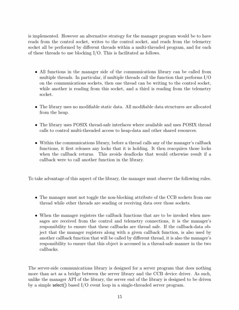
is implemented. However an alternative strategy for the manager program would be to havereads from the control socket, writes to the control socket, and reads from the telemetrysocket all be performed by different threads within a multi-threaded program, and for eachof these threads to use blocking I/O. This is facilitated as follows.
• All functions in the manager side of the communications library can be called frommultiple threads. In particular, if multiple threads call the function that performs I/Oon the communications sockets, then one thread can be writing to the control socket,while another is reading from this socket, and a third is reading from the telemetrysocket.
• The library uses no modifiable static data. All modifiable data structures are allocatedfrom the heap.
• The library uses POSIX thread-safe interfaces where available and uses POSIX threadcalls to control multi-threaded access to heap-data and other shared resources.
• Within the communications library, before a thread calls any of the manager’s callbackfunctions, it first releases any locks that it is holding. It then reacquires those lockswhen the callback returns. This avoids deadlocks that would otherwise result if acallback were to call another function in the library.
To take advantage of this aspect of the library, the manager must observe the following rules.
• The manager must not toggle the non-blocking attribute of the CCB sockets from onethread while other threads are sending or receiving data over those sockets.
• When the manager registers the callback functions that are to be invoked when mes-sages are received from the control and telemetry connections, it is the manager’sresponsibility to ensure that these callbacks are thread safe. If the callback-data ob-ject that the manager registers along with a given callback function, is also used byanother callback function that will be called by different thread, it is also the manager’sresponsibility to ensure that this object is accessed in a thread-safe manner in the twocallbacks.
The server-side communications library is designed for a server program that does nothingmore than act as a bridge between the server library and the CCB device driver. As such,unlike the manager API of the library, the server end of the library is designed to be drivenby a simple select() based I/O event loop in a single-threaded server program.
15

1.9 Library usage caveats
The following general rules must be observed by the manager when calling functions in thepublic API of the communications library.
• None of the library functions are async-signal-safe, and should thus not be called fromsignal handlers.
• Some callback functions are passed pointers to arrays as arguments. These functionsmust assume that these pointers, and the arrays to which they point, become invalid assoon as the callback function returns. If longer term access to their contents is needed,the callback must make its own copy.
For example, when log messages are sent to the manager by the log-message callback,the error message string is discarded and its array potentially reused for a differentmessage as soon as the callback function returns.
Incoming messages are delivered to the manager via callback functions that the manager pro-vides. The library header-files provide macros for declaring and prototyping these functions.For example, a typical callback definition macro might be the following,
#define CCB_EXAMPLE_CALLBACK_FN(fn) int (fn)(void *data, int x)
Now, say that the manager wanted to define a callback function of this type called my-callback(). Its function prototype would be written like:
static CCB_EXAMPLE_CALLBACK_FN(my_callback);
and its definition written like,
static CCB_EXAMPLE_CALLBACK_FN(my_callback)
{
...the body of the function...
}
It is recommended that these callback function macros be used, because if additions everneed to be made to the argument lists of any of the callback functions, a simple recompileof the manager will then automatically incorporate the new definitions.
16

1.10 Shared libraries and their versioning
The communications libraries are compiled as shared libraries under both Solaris and Linux.This brings the possibility of strict versioning support from the respective linkers, and theability to restrict which symbols are exported to application programs, thus preventing theunsupported use of internal library functions. The versioning scheme implemented by theLinux and Solaris run-time linkers is documented at
http://www.usenix.org/publications/library/proceedings/als2000/browndavid.html
The basic idea is that libraries have three version numbers, a major number, a minor numberand a micro number. These are used as follows:
• When a library update only involves modifications to the internal implementation ofthe library, without any changes being made to the public interface, the micro versionnumber is incremented by 1. In this case an application can safely run against the newshared library without needing to be recompiled.
• When the existing public interface is augmented with the addition of new functions,without any changes being made to the interfaces of the existing public functions, theminor version number is incremented by one, and the micro version number is reset tozero. In this case a previously compiled application can run against the updated sharedlibrary, without needing to be recompiled, but will obviously need to be recompiled ifit wishes to make use of any of the added features.
• When any aspect of the existing public interface is changed, the major version number isincremented by one, and the minor and micro version numbers are reset to zero. Sincethe new library isn’t backwardly compatible with the previous one, the applicationneeds to be recompiled before the run-time linker will allow it to use the new libraryversion. This kind of update should be avoided if at all possible.
To enhance the capabilities of the Solaris and Linux run-time linkers, a map file is usedwhen a shared library is created. This lists the symbols that were added in each new minorversion of the library. This allows the run-time linker to check that all of the functions thatthe application actually uses, are provided in the current version of the shared library, evenif the current shared library is older than the one that the application was originally linkedagainst.
Configuration of the communication library makefiles to support this scheme are performedby a standard autoconf configure script which, if need be, can later be tailored to futureoperating systems. Modifications are performed by editing the file configure.in, which isheavily commented, then running the autoconf program to generate a configure script fromthis.
17

Chapter 2
Installation
2.1 Getting the source code
The latest version of the library code, plus this documentation can be downloaded from,
http://www.astro.caltech.edu/~mcs/GBT/ccb.tar.gz
To extract the contents of this tar file, type,
gunzip -c ccb.tar.gz | tar xf -
This will create a directory called CCB/ in the current directory. Within this directory thesource code is collected under sub-directories of CCB/code, documentation is collected underthe CCB/doc directory, and the CCB firmware and modelsim simulation scripts are found inthe CCB/firmware directory. The remaining files in the CCB/ directory, are associated withthe build procedure of the code and documentation.
2.2 The basics of installation
Although the code and documentation can be compiled in-place, within the top-level CCBsub-directory, it is recommended that instead you create a separate build directory, andcompile from there. This keeps the source-code hierarchy clean of intermediate files andfinal binary files, and thus makes it easier to copy or mirror the code between differentcomputers. You can also then simply delete the build directory, to get rid of intermediate
18

files, without affecting the files in the source-code hierarchy, or delete the CCB/ directory,without also deleting the build directory.
So, for example, a complete installation from scratch would look as follows:
gunzip -c ccb.tar.gz | tar xf -
mkdir build
cd build
../CCB/configure
make
make install
You could then optionally either delete the build directory, or type:
make distclean
to remove any files that the makefile and configure script generated. To just remove filesthat were built by the makefile, without also removing those files that were created by theconfigure script, you would instead type:
make clean
After doing this, you could then re-run make from scratch, without having to run the config-ure script again. This is a good way to ensure that everything that needs to be recompiled,is recompiled, after a change to a source file.
The provided autoconf configuration script, CCB/configure, currently only knows about So-laris and Linux, but its template script, CCB/configure.in is heavily commented to facilitatethe addition of configurations for other operating systems. The only parameters of the con-figuration that need to be changed from one operating-system to the next, are those thatrefer to shared library creation and versioning.
2.3 Compiling in a different directory
As shown in the above example, compilation can be performed in a different directory fromthe one that contains the source code, simply by going to the chosen build-directory, andrunning the CCB/configure script from there, via a relative or absolute directory path to theconfigure script.
This works, because the makefile that the configure script generates, contains pathnames toeach component that it needs.
19
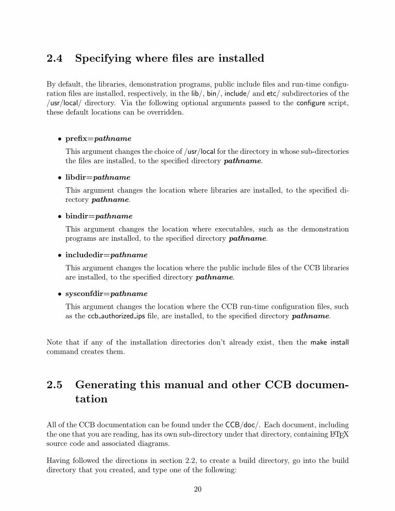
2.4 Specifying where files are installed
By default, the libraries, demonstration programs, public include files and run-time configu-ration files are installed, respectively, in the lib/, bin/, include/ and etc/ subdirectories of the/usr/local/ directory. Via the following optional arguments passed to the configure script,these default locations can be overridden.
• prefix=pathname
This argument changes the choice of /usr/local for the directory in whose sub-directoriesthe files are installed, to the specified directory pathname.
• libdir=pathname
This argument changes the location where libraries are installed, to the specified di-rectory pathname.
• bindir=pathname
This argument changes the location where executables, such as the demonstrationprograms are installed, to the specified directory pathname.
• includedir=pathname
This argument changes the location where the public include files of the CCB librariesare installed, to the specified directory pathname.
• sysconfdir=pathname
This argument changes the location where the CCB run-time configuration files, suchas the ccb authorized ips file, are installed, to the specified directory pathname.
Note that if any of the installation directories don’t already exist, then the make installcommand creates them.
2.5 Generating this manual and other CCB documen-
tation
All of the CCB documentation can be found under the CCB/doc/. Each document, includingthe one that you are reading, has its own sub-directory under that directory, containing LATEXsource code and associated diagrams.
Having followed the directions in section 2.2, to create a build directory, go into the builddirectory that you created, and type one of the following:
20

• make dvi
This builds dvi-format files of the documentation, which can then be read with thexdvi program.
• make ps
This builds postscript versions of the documentation, ready for printing on a postscriptprinter, or viewing with a program like ghostview. As a side-effect, dvi-format files arealso built.
• make pdf
This builds PDF files for each of the documents, ready to be viewed with programssuch as Adobe Acrobat. As a side-effect, dvi-format files are also built.
If the configure script found the optional LATEX hyperref package, the dvi and pdf versionsof the manual include hypertext links. Beware that these links all point to the startsof sections or sub-sections, so a reference in the index to a particular page, actuallylinks to the start of the section that contains that page.
To make just a particular document, simply run make with the name of the document thatyou want. For example, tpying:
make ccb_network_interface.pdf
would create a PDF file of the CCB Network Interface document, with the above name. Thenames of the PDF versions of all of the available documents are as follows:
• ccb network interface.pdfThe document that you are currently reading.
• ccb diagnostic programs.pdfDocumentation of a suite of CCB diagnostic programs.
• ccb fpga design.pdfDocumentation of the CCB firmware.
• ccb epp driver.pdfDocumentation of the EPP driver that controls the CCB firmware.
• ccb gpio driver.pdfDocumentation of the I/O card driver that monitors the general status of the CCB,and drives the front-panel LEDs.
• ccb external hardware interfaces.pdfDocumentation of the goals and rational behind the eventual design of the externalhardware interfaces of the CCB, intermixed with the description of an early potentialimplementation, of which only a few parts were actually used.
21

Note that there is no make install target for the documentation, because there isn’t anstandard for where such documentation should be installed, and autoconf doesn’t provide adirectory option for this, for use in configure scripts. Thus the PDF, DVI and PS files aresimply left in the build directory, and should be copied by hand to their final destinations.
2.6 Testing the libraries using the demonstration pro-
grams
In addition to building the CCB client and CCB server libraries, the makefile also compiles,links and installs a simple, GUI-based, demonstration client program, that can be used fortesting and controlling the CCB server program, in place of the CCB manager.
Since the installation paths of the shared libraries and the CCB configuration files are embed-ded within the executables, it is necessary to run the “make install” step before attemptingto run the demonstration programs. Thus if you wish to test out the demonstration pro-grams before performing the final installation, first perform the installation in a temporaryplace, then later recompile and reinstall in the final place. For example, to install under/home/mcs/tmp, one would do the following steps.
./configure --prefix=/home/mcs/tmp
make install
Later on, to perform the final installation in subdirectories of a different directory, onewould repeat this, but replacing the /home/mcs/tmp in the above, with the path of thedesired directory.
Having installed the CCB software, check that the ccb authorized ips file, which is by-defaultinstalled in the etc/ subdirectory of the chosen top-level installation directory, containsan entry that covers the IP address of the computer on which you will be running thedemonstration client (see page 24).
Now start two terminal windows, either on the same host, or on two different hosts. For thesake of example, assume that when you ran the configure script, you passed it the argumentsprefix=$HOME/tmp, to have the software installed under a temporary directory in your homedirectory, and that this home directory is visible from both of the hosts that are running thetwo terminals. Now in one terminal window type:
$HOME/tmp/bin/ccbserver
and in the other terminal window type:
22

$HOME/tmp/bin/ccb_demo_client
Provided that Tcl/Tk is installed on your system, and that the configure script found it, thedemonstration client program will now display a graphical user interface, giving you write-access to all CCB configuration parameters and CCB commands. To connect this programto the CCB server, type the name of the computer on which you are running ccbserver,into the entry area to the right of the Connect button, then press this button. The loggingarea should then display two messages from the CCB server, saying that it is acceptingnew control and telemetry connections. If this doesn’t happen, it probably means thatat the time when ccbserver was started, the ccb authorized ips file didn’t contain an entryauthorizing connections from the computer on which you are running the ccb demo clientprogram. If so, restart ccbserver after adding an appropriate entry to the latter file.
Assuming that this all worked, the CCB server will initially have all telemetry except log-messages turned off. As a reminder of this, the Off button is initially colored bright red.To enable all telemetry, press the “Ready” button. After doing this, you should see fakeintegrated data being displayed in the second-to-last beige area from the bottom of the GUI,roughly once per second. After every ten of these updates, the monitoring area below theintegrated data area will also display updated monitor data. The initial rates at which theintegrated and monitoring data are received and displayed are set by the default configurationparameters shown in the window. These can subsequently be changed. In particular, if youchange the number in the entry-area next to the “Configure Monitoring” button, and thenpress the latter button, the modified number will be used to determine how often fakemonitor-data updates are sent.
As described later, changes to the phase-switch, cal-diode, timing, and sampler configura-tion parameters, in the top three panes of the window, only take effect when a new scan,dump-scan, or intra-scan is started. Thus to change the integration period of the fake in-tegrations, you would change, say the “Integ period” configuration parameter in the “timingconfiguration” window-pane, then press either the “Start scan”, “Stop scan”, or “Dump scan”buttons, to start a new scan that operates according to these parameters.
By default, the demonstration client attempts to interact with the real CCB hardware, viathe ccbserver program. Alternatively, the CCB server can be instructed to substitute a built-in simulation of the CCB hardware. In the ccb demo client program, this is done by selectingthe Virtual entry of the Load Driver option-menu. This virtual-CCB simulation can be usedfor off-line testing of the manager program. It prints what it is doing, on the parent terminalof the CCB server program, indicating any effects that commands sent by the manager,would have on the real hardware. The simulated CCB also sends back faked integration andmonitoring data, timed and flagged according to the current CCB configuration parameters.Diagnostic programs also receive simulated dump-mode data from the dump-mode port ofthe CCB server, while the virtual CCB simulation is active.
23

2.6.1 ccb dummy client
In addition to the interactive demonstration client that was introduced above, a non-interactivedemonstration client called ccb dummy client is provided. This initiates a non-blocking con-nection to the demonstration server, queues a full set of configuration and operating com-mands to be sent to the server, once the connection has been established, then enters aselect() driven event loop. The event loop then informs the communications library when-ever it detects an I/O event on any of the sockets that the library tells it to watch. Oncethe library receives confirmation of the completion of the non-blocking control connection, itsends the previously queued commands using non-blocking I/O, and watches for replies fromthe server. The library then forwards replies from the server to the demonstration client,by calling the callback functions that the demonstration program provided it. For the sakeof demonstration, these callbacks display the contents of the replies on the terminal. Thisminimal program, which was written before the interactive demo program, is potentiallyuseful for speed tests, since the GUI display of 1ms integration updates would be too fastto follow by eye, even if one were confident that the X server could keep up with this rate.For example, using this program with the demo server, one can verify that the demo servercan’t generate integrations more frequently than 10ms. This is expected, because that is thegranularity of the Linux timers that govern the event loop of the virtual driver in the CCBserver program.
This program also provides a simple working example of how to use the C interface, andcan act as a basis for custom test programs, such as one that writes integrated data to diskfor later examination. Having said this, the Tcl interface described later is probably moreconvenient for quick throw-away test programs.
2.7 Run-time configuration files
Currently, the communications library that the CCB-server uses to talk to managers, requiresone configuration file, as described below. In future there could conceivably be more. Bydefault, the directory in which these files are installed is /usr/local/etc/, but this can bechanged during installation, as described earlier on page 19.
2.8 The ccb authorized ips configuration file
This configuration file lists the host computers that are authorized to connect to the CCBserver. It consists of one IP address per line. Within these addresses, each numeric fieldcan optionally be replaced with a * wild-card. For example, the following lines authorize allcomputers within the Green Bank subnets, plus the computer on which the CCB server isrunning.
24
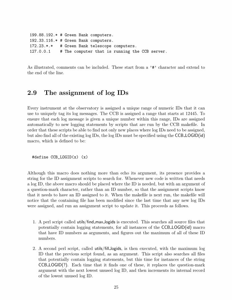
199.88.192.* # Green Bank computers.
192.33.116.* # Green Bank computers.
172.23.*.* # Green Bank telescope computers.
127.0.0.1 # The computer that is running the CCB server.
As illustrated, comments can be included. These start from a ’#’ character and extend tothe end of the line.
2.9 The assignment of log IDs
Every instrument at the observatory is assigned a unique range of numeric IDs that it canuse to uniquely tag its log messages. The CCB is assigned a range that starts at 12445. Toensure that each log message is given a unique number within this range, IDs are assignedautomatically to new logging statements by scripts that are run by the CCB makefile. Inorder that these scripts be able to find not only new places where log IDs need to be assigned,but also find all of the existing log IDs, the log IDs must be specified using the CCB LOGID(id)macro, which is defined to be:
#define CCB_LOGID(x) (x)
Although this macro does nothing more than echo its argument, its presence provides astring for the ID assignment scripts to search for. Whenever new code is written that needsa log ID, the above macro should be placed where the ID is needed, but with an argument ofa question-mark character, rather than an ID number, so that the assignment scripts knowthat it needs to have an ID assigned to it. When the makefile is next run, the makefile willnotice that the containing file has been modified since the last time that any new log IDswere assigned, and run an assignment script to update it. This proceeds as follows.
1. A perl script called utils/find max logids is executed. This searches all source files thatpotentially contain logging statements, for all instances of the CCB LOGID(id) macrothat have ID numbers as arguments, and figures out the maximum of all of these IDnumbers.
2. A second perl script, called utils/fill logids, is then executed, with the maximum logID that the previous script found, as an argument. This script also searches all filesthat potentially contain logging statements, but this time for instances of the stringCCB LOGID(?). Each time that it finds one of these, it replaces the question-markargument with the next lowest unused log ID, and then increments its internal recordof the lowest unused log ID.
25

3. Finally, after all log IDs have been assigned in the above manner, the find max logidsscript is run a second time, to determine the new maximum log ID. This numberis then passed to a bourne-shell script called utils/write logid header, which writes apublic header file called ccblogid.h. This header file defines the value of a macro calledCCB MAX LOGID to have the maximum log ID that is currently used by the CCBlibraries.
Given that the CCB installation procedure doesn’t know anything about the source files inthe CCB manager, if the manager needs to create its own log IDs, without having to worryabout clashing with numbers that the CCB libraries have assigned to themselves, then oneway to do this would be to include the ccblogid.h script, and specify new log-ids as offsetsfrom the value of the CCB MAX LOGID macro. Clearly the makefiles for these programswould need to specify the ccblogid.h header file as a dependency for any source files thatassigned log IDs in this way, and the manager would need to be recompiled every time thatthe CCB libraries were updated. A downside of this approach would be that the IDs ofstatements in the manager would change whenever this happened. It might thus be bettersimply to assign the manager a range of IDs significantly above the maximum number thatthe CCB libraries use, and simply check the ccblogid.h header file by eye, every so often, tomake sure that the two ranges aren’t getting close to overlapping.
To force the CCB makefile to reassign a contiguous range of log IDs, from scratch, to all ofthe source files of the CCB libraries, the makefile provides the reset logids target. This runsa script called utils/clear logids, which replaces all instances of the CCB LOGID() macro withthe string CCB LOGID(?), such that the next time that the makefile is executed, log IDs areassigned from scratch.
26

Chapter 3
The common parts of the CCB serverand client APIs
The libccbcommon library includes functions, datatypes and a few macros, that are usedby all of the Caltech parts of the CCB software, and the CCB manager. Since each of theother CCB shared libraries are linked with this library, when they are created by the CCBmakefile, there is no need to explicitly link with this library, when compiling a CCB programthat uses one or more of the other libraries.
3.1 The configuration of the CCB
CCB configuration parameters are exchanged with the client and server libraries using CCB-Config objects. Since these objects are opaque, external functions must be used both toallocate them, and to modify and query their contents. This section describes these func-tions.
The new CCBConfig() function allocates CCBConfig objects from the heap, and initializesthem with the default power-on configuration of the CCB. On error it returns NULL.
CCBConfig *new_CCBConfig(void);
To reclaim the resources of a redundant CCBConfig object, the del CCBConfig function mustbe called to return the object to the heap.
CCBConfig *del_CCBConfig(CCBConfig *cnf);
27

The ccb default config() function can be used to replace the current configuration in a CCB-Config object with the power-on-default configuration of the CCB. It returns non-zero andsets errno to EINVAL if its argument is NULL. Otherwise it returns 0.
int ccb_default_config(CCBConfig *cnf);
The ccb copy config() function copies the contents of the configuration object, orig, to theconfiguration object dest. It returns non-zero and sets errno to EINVAL if either of itsarguments is NULL. Otherwise it returns 0.
int ccb_copy_config(const CCBConfig *orig, CCBConfig *dest);
The ccb check config() function checks whether the configuration parameters installed withina given configuration object are valid, and returns 0 if they are. Otherwise, it returns non-zeroand places an error message in the buffer that the caller passes via the errmsg argument. Theallocated dimension of this buffer must be provided in the errdim argument. Error messageswhose length, including the standard ’\0’ terminator, exceed this size are truncated to fit.
int ccb_check_config(CCBConfig *cnf, size_t errdim, char *errmsg);
The CCB configuration parameters are partitioned into a number of groups. These groupsare enumerated by the CCBConfigType datatype. Note that the values are integer powers oftwo, such that their values correspond to single bits within an integer.
typedef enum {
CCB_CNF_PHASE_SWITCHES = 1, /* Phase-switch parameters */
CCB_CNF_CAL_DIODES = 2, /* The calibration-diode parameters */
CCB_CNF_TIMING = 4, /* The hardware timing parameters */
CCB_CNF_SAMPLER = 8, /* The sampler configuration parameters */
/*
* The union of all of the above.
*/
CCB_CNF_ALL = CCB_CNF_PHASE_SWITCHES | CCB_CNF_CAL_DIODES |
CCB_CNF_TIMING | CCB_CNF_SAMPLER
} CCBConfigType;
The ccb diff config() function compares two CCB configuration objects and returns the bit-wise union of the enumerators of the configuration groups whose parameters differ.
unsigned ccb_diff_config(CCBConfig *ca, CCBConfig *cb);
28

The following sub-sections describe the functions that are used to set and query the pa-rameters of each of the configuration groups within a CCB configuration object. Each ofthe querying functions returns the parameters as a group, encapsulated within a structure.The ccb set config() function provides a means to set the whole configuration using theseencapsulating arguments.
int ccb_set_config(CCBConfig *cnf,
const CCBPhaseSwitchCnf *phase,
const CCBCalDiodeCnf *cal,
const CCBTimingCnf *timing,
const CCBSamplerCnf *sampler);
Since any of the configuration arguments can be NULL, one can use this function to updateeither the whole configuration or just a subset of the configuration groups. The datatypesof the configuration arguments are described in detail in the following sections. On error,this function returns non-zero and sets errno accordingly. Otherwise it returns 0.
3.1.1 The configuration of the phase switches
The digital backend generates two phase-switch TTL control signals, both of which are usedby the 1cm receiver, and only one of which is used by the 3mm receiver. The CCB serversupports the 16 phase-switching modes illustrated in figure 3.1.
Each row of this diagram displays the 4 possible cycles of a particular combination of activeswitches, with each of these cycles corresponding to a different pair of initial phase-switchstates.
Note that whereas the number of A/D samples per phase-switch state in this diagram is justan example of what can be configured, the number of phase-switch states per cycle is fixedby the number of switches that are active, and is thus not otherwise configurable.
The configuration of the phase switches within a CCB configuration object can be changedby calling ccb set phase switch cnf().
int ccb_set_phase_switch_cnf(CCBConfig *cnf,
unsigned short active_switches,
unsigned short closed_switches,
unsigned short samp_per_state);
The arguments of this function are interpreted as follows.
29

Figure 3.1: Example phase-switching cycles
30
• Which switches are active? (active switches)
This specifies the set of phase switches that are to be switched during phase-switchingcycles, expressed as a bitwise union of CCBPhaseSwitches enumerators.
typedef enum {
CCB_NO_PHASE_SWITCHES = 0, /* Neither of the phase switches */
CCB_PHASE_SWITCH_A = 1, /* phase switch A */
CCB_PHASE_SWITCH_B = 2, /* phase switch B */
CCB_ALL_PHASE_SWITCHES = /* Both phase switches */
CCB_PHASE_SWITCH_A | CCB_PHASE_SWITCH_B
} CCBPhaseSwitches;
Any phase switches that aren’t specified to be switched, are held in the positionsindicated by the closed switches argument.
• Which switches start closed? (closed switches)
This argument specifies the set of phase switches that are to be on at the start of eachnew phase-switch cycle, expressed as a bitwise union of CCBPhaseSwitches enumerators.
• Samples per phase-switch state (samp per state)
This parameter configures the number of A/D samples that are integrated betweenchanges in the states of either phase-switch. The range of supported values are givenby the following macros from ccbconstants.h.
#define CCB_MIN_SAMP_PER_STATE 250U /* 25us */
#define CCB_MAX_SAMP_PER_STATE 65535U /* 6.5535ms */
The ccb set phase switch cnf() function normally returns zero, but returns non-zero and setserrno appropriately on error. Beware that a successful return doesn’t necessarily mean thatthe configuration is valid when combined with other configuration parameters. To verify this,the ccb check config() function should be called once all of the configuration parameters havebeen set to their desired values.
The configuration parameters of the phase switches within a CCB configuration object canbe queried using the ccb get phase switch cnf() function.
int ccb_get_phase_switch_cnf(const CCBConfig *cnf,
CCBPhaseSwitchCnf *pars);
This returns the phase-switch configuration parameters in the variable pointed at by the parsargument. This is a variable of type CCBPhaseSwitchCnf.
31
typedef struct {
unsigned short active_switches; /* Which switches are active? */
unsigned short closed_switches; /* Which switches start closed? */
unsigned short samp_per_state; /* ADC samples per phase-switch */
/* state. */
} CCBPhaseSwitchCnf;
The members of this datatype have the same meanings as the synonymous arguments of theccb set phase switch cnf() function.
The ccb get phase switch cnf() function normally returns zero, but if either cnf or pars areNULL, it returns non-zero and sets errno to EINVAL.
3.1.2 The configuration of the calibration diodes
The digital backend generates two noise-diode TTL control signals, both of which are usedby the 1cm receiver, and only one of which is used by the 3mm receiver. Since the devicedriver sets the on/off state of these diodes at the boundaries between integrations, eachcal-diode state lasts an integral number of integrations. For each scan it is thus necessaryto specify the sequence of states that the noise-diodes should go through, and how manyintegrations each state should last. This sequence starts with the first integration of thescan, and thereafter is repeated indefinitely until the next scan is started. Since it isn’t clearhow many calibration steps might be needed for future observations, the maximum numberof steps is parameterized as CCB MAX NCAL, which is defined in the public include file ofthe communications library.
#define CCB_MAX_NCAL 32
The configuration of the calibration diodes within a CCB configuration object is changed bycalling the ccb set cal diode cnf() function.
int ccb_set_cal_diode_cnf(CCBConfig *cnf,
unsigned short ncal,
const short *diode_states,
const unsigned long *diode_times);
The arguments of this function, are as follows.
• The number of calibration steps (ncal)
32

The number of steps in the calibration diode state machine. This must be less than orequal to CCB MAX NCAL.
Note that a value of zero can be used if the calibration diodes are to be left turned offthroughout the parent scan.
• The ncal calibration diode states (diode states)
The first ncal elements of this array specify the set of calibration diodes that are tobe turned on for the duration of the corresponding step of the calibration diode statemachine. Each element is a bitwise union of CCBCalDiodes enumerators.
typedef enum {
CCB_NO_CAL_DIODES = 0, /* Neither calibration diode */
CCB_CAL_DIODE_A = 1, /* Calibration diode A */
CCB_CAL_DIODE_B = 2, /* Calibration diode B */
CCB_ALL_CAL_DIODES = /* Both calibration diodes */
CCB_CAL_DIODE_A | CCB_CAL_DIODE_B
} CCBCalDiodes;
This argument can be NULL if ncal is 0.
• The durations of the ncal cal-diode states (diode times)
Each element of the first ncal elements of this parameter, specifies the duration ofthe state in the corresponding element of the diode states parameter. The duration isinterpreted as an integer number of integrations.
For the minimum integration time of 1ms, the use of a 32-bit value translates to amaximum duration of 48 days. This is clearly overkill, but a 16-bit value would onlysupport up to 65 seconds per state, which might not be enough.
This argument can be NULL if ncal is 0.
The ccb set cal diode cnf() function normally returns zero, but returns non-zero and setserrno appropriately on error. Beware that a successful return value doesn’t necessarily meanthat the configuration is valid when combined with other configuration parameters. To verifythis, the ccb check config() function should be called once all of the configuration parametershave been set to their desired values.
The calibration-diode configuration parameters, within a given CCB configuration object,can be queried by calling the ccb get cal diode cnf() function.
int ccb_get_cal_diode_cnf(const CCBConfig *cnf,
CCBCalDiodeCnf *pars);
This returns the cal-diode configuration parameters in the variable pointed at by the parsargument. This is a variable of type CCBCalDiodeCnf.
33

typedef struct {
unsigned short ncal; /* The number of steps per */
/* calibration cycle. */
unsigned short diode_states[CCB_MAX_NCAL]; /* The set of calibration */
/* diodes that are ON */
/* during each of the */
/* ’ncal’ steps. */
unsigned long diode_times[CCB_MAX_NCAL]; /* The number of */
/* integrations of each */
/* of the ’ncal’ steps. */
} CCBCalDiodeCnf;
The members of this datatype have the same meanings as the synonymous arguments of theccb set cal diode cnf() function.
The ccb get cal diode cnf() function normally returns zero, but if either cnf or pars are NULL,it returns non-zero and sets errno to EINVAL.
3.1.3 The configuration of hardware timing parameters
The hardware timing configuration parameters determine the durations of configurable timersin the CCB hardware. Within a CCB configuration object, these parameters are changedby calling ccb set timing cnf().
int ccb_set_timing_cnf(CCBConfig *cnf,
unsigned short phase_switch_dt,
unsigned long diode_rise_dt,
unsigned long diode_fall_dt,
unsigned long integ_period,
unsigned short roundtrip_dt,
unsigned short holdoff_dt,
unsighed short adc_delay_dt);
The arguments of this function are interpreted as follows.
• Phase-switch blanking interval (phase switch dt)
This specifies how much of the sample interval is blanked, while the phase switchessettle after phase-switch transitions. It is expressed as an integer multiplier of 100ns.It has a minimum of 0, and a maximum that is set by the following macro fromccbconstants.h.
34

#define CCB_MAX_PHASE_SWITCH_DT 255U /* 2^8 - 1 */
• Calibration diode rise time (diode rise dt)
This specifies the interval during which the calibration diode signals are unstable afterbeing newly switched on. It is expressed as an integer multiplier of 100ns, and hasa maximum value that is parameterized the the following macro definition in ccbcon-stants.h.
#define CCB_MAX_DIODE_RISE_DT 4294967295U /* 2^32 - 1 */
• Calibration diode fall time (diode fall dt)
This specifies the interval during which any residual calibration diode signals remainpresent after being newly switched off. It is expressed as an integer multiplier of 100ns,and has a maximum value that is parameterized the the following macro definition inccbconstants.h.
#define CCB_MAX_DIODE_FALL_DT 65535U /* 2^16 - 1 */
• The integration period (integ period)
This specifies the number of phase-switch cycles that are to be co-added to form theintegrations that are sent to the manager. The physical length of time that this cor-responds to depends on the number of samples per phase-switch cycle, and can becalculated by calling the ccb integration duration() function. It has a maximum valuethat is parameterized the the following macro definition in ccbconstants.h.
#define CCB_MAX_INTEG_PERIOD 65535U /* 2^16 - 1 */
• The round-trip propagation delay (roundtrip dt)
This specifies the expected delay between the CCB hardware toggling any of the switchcontrol-lines, and the first effects of this reaching the CCB digital integrators. Theroundtrip dt parameter specifies this in units of 100ns, and has a maximum value ofCCB MAX ROUNDTRIP DT, which is a macro which is defined in ccbconstants.h, asfollows.
#define CCB_MAX_ROUNDTRIP_DT 255U /* 2^8 - 1 */
The specified roundtrip delay should be a lower-limit to the expected delay, such thatthe CCB hardware can safely assume that all data that arrive at the integrators forthis long after a switch-change is commanded, can be assumed to be associated withthe previous states of the phase and cal-diode switches. The underestimate of thisparameter should be compensated by overestimating the cal-diode and phase-switchsettling times.
35

Note that the predictable contributions to this delay include the propagation delayof the opto-isolators at the ends of the receiver control-cables, the group-delay of the2MHz low-pass Bessel filters, and the pipeline delays of the ADCs and the input latchesof the CCB hardware. These add up to about 700ns. When the group-delays of theRFI filters, control-signal pulse shapers, and the rest of the electronics are taken intoaccount, the final round-trip delay will thus probably be over 1µs. The maximumsupported delay of 255× 100ns, is thus 25 times greater than the expected value.
The default value of roundtrip dt is 5, which corresponds to a physical delay of 500ns,which is probably overly-cautious.
• The interrupt-generation holdoff delay (holdoff dt)
This sets the minimum interval between the interrupts that the CCB hardware cangenerate, and has three goals.
1. To prevent the CPU from locking up if an interrupt source in the CCB hardware,for some unforeseen reason, attempts to generate interrupts at an extreme rate.
2. To reduce the number of interrupts that need to be sent, by allowing interruptsof multiple interrupt sources to be signaled by one hardware interrupt.
3. To set the repeat interval at which unacknowledged interrupts are to be signaledagain.
The actual holdoff interval that corresponds to a given value of the holdoff dt parameter,is given by.
dt = 25.6µs× (holdoff dt + 1) (3.1)
Thus, since the holdoff dt parameter is allowed to take any value in the range 0-CCB-MAX HOLDOFF DT, where CCB MAX HOLDOFF DT is a macro which is defined inccbconstants.h, as follows,
#define CCB_MAX_HOLDOFF_DT 31U /* 5 bits */
the supported range of holdoff intervals is 25.6µs – 0.8192ms. The lower-limit waschosen to be just over the claimed average interrupt latency of the Linux 2.6 kernel, inan attempt to ensure that regardless of the configuration parameters, the Linux kernelwill not be overwhelmed by CCB interrupts. The upper-limit is set to be less thanthe minimum, 1ms, integration time. This is necessary, since integration-configurationinterrupts must be generated and responded to, on average, within less than the in-tegration time. The default value of the holdoff dt parameter is 7, which translatesto a physical holdoff interval of 204.8µs. Note that this is larger than the reported181µs maximum interrupt latency of the Linux 2.6 kernel, and should thus reduce theprobability of interrupts having to be redundantly signaled when not acknowledgedquickly. At the same time, it is small enough to allow several integration-configurationinterrupts to be generated and responded to per integration period.
36

Note that the above-quoted characteristics of the Linux 2.6 kernel were obtained froman article at the following URL.
http://www.linuxdevices.com/articles/AT7751365763.html
• The ADC clock delay (adc delay dt)
The clock signal that is used to clock the ADCs is a phase-shifted copy of the globalFPGA clock. The phase shift is implemented by delaying a copy of the global FPGAclock by adc delay dt×10ns. The adc delay dt parameter has a maximum value that isparameterized by the following macro in ccbconstants.h.
#define CCB_MAX_ADC_DELAY 9U
The ccb set timing cnf() function normally returns zero, but returns non-zero and sets errnoappropriately on error. Beware that a successful return doesn’t necessarily mean that theconfiguration is valid when combined with other configuration parameters. To verify this,the ccb check config() function should be called once all of the configuration parameters havebeen set to their desired values.
Note that this function will complain, not only if the above parameters are outside the rangesmentioned above, but also if the resulting physical duration of each integration is less thanthe value of the following macro, which is defined in ccbconstants.h.
#define CCB_MIN_INTEG_DT 1000000 /* 1000000 x 1ns = 1ms */
The configuration parameters of the hardware timing within a CCB configuration object canbe queried using the ccb get timing cnf() function.
int ccb_get_timing_cnf(const CCBConfig *cnf, CCBTimingCnf *pars);
This returns the timing configuration parameters in the variable pointed at by the parsargument. This is a variable of type CCBTimingCnf.
typedef struct {
unsigned short phase_switch_dt; /* The settling time of the phase */
/* switches. */
unsigned long diode_rise_dt; /* The rise time of a cal diode */
unsigned long diode_fall_dt; /* The fall time of a cal diode */
unsigned long integ_period; /* The integration period */
unsigned short roundtrip_dt; /* The delay between toggling a */
37
/* receiver control line and */
/* the first effects reaching */
/* the CCB integrators. */
unsigned short holdoff_dt; /* The minimum time between */
/* generating CPU interrupts */
/* is 25.6us*(holdoff_dt+1) */
unsigned short adc_delay_dt; /* The offset of the ADC clock */
/* from the main FPGA clock, */
/* expressed as a multiple of */
/* 10ns. */
} CCBTimingCnf;
The members of this datatype have the same meanings as the synonymous arguments of theccb set timing cnf() function.
The ccb get timing cnf() function normally returns zero, but if either cnf or pars are NULL,it returns non-zero and sets errno to EINVAL.
3.1.4 The configuration of sampler control parameters
The sampler configuration parameters control the digitized samples that are integrated innormal integration mode, and collected verbatim, in dump mode. Within a CCB configura-tion object, these parameters are changed by calling ccb set sampler cnf().
int ccb_set_sampler_cnf(CCBConfig *cnf, CCBSampleType sample_type);
The arguments of this function are interpreted as follows.
• The digitized samples to integrate or dump (sample type)
This argument specifies what type of digitized samples are to be used by the hardware.These can be either the real ADC samples, or fake pseudo-random samples. The latterare used for testing the digital parts of the CCB hardware. The value of this argumentmust be one of the following enumerated values.
typedef enum {
CCB_ADC_SAMPLES, /* Use the real ADC samples */
CCB_FAKE_SAMPLES /* Use fake pseudo-random samples */
} CCBSampleType;
The default configuration sets this parameter to CCB ADC SAMPLES.
38

The ccb set sampler cnf() function normally returns zero, but returns non-zero and sets errnoappropriately on error. Beware that a successful return doesn’t necessarily mean that theconfiguration is valid when combined with other configuration parameters. To verify this,the ccb check config() function should be called once all of the configuration parameters havebeen set to their desired values.
The configuration parameters of the hardware sampler within a CCB configuration objectcan be queried using the ccb get sampler cnf() function.
int ccb_get_sampler_cnf(const CCBConfig *cnf, CCBSamplerCnf *pars);
This returns the sampler configuration parameters in the variable pointed at by the parsargument. This is a variable of type CCBSamplerCnf.
typedef struct {
unsigned short sample_type; /* The type of digitizer samples */
} CCBSamplerCnf;
The members of this datatype have the same meanings as the synonymous arguments of theccb set sampler cnf() function.
The ccb get sampler cnf() function normally returns zero, but if either cnf or pars are NULL,it returns non-zero and sets errno to EINVAL.
3.2 Textual configuration
The previously described functions manipulate a CCB configuration object using binaryrepresentations of parts of the configuration. This is efficient, but tedious for people wantingto write quick diagnostic programs. Thus, primarily for the use of diagnostic programs thatuse the libccbtestclient library, to be described later, a simpler method has been provided,that uses human-readable parameter assignments in text-strings.
The following is an example of a configuration string.
"integ_period=100 active_switches=AB"
This would change the integ period parameter, which sets the number of phase-switch cyclesper integration-period, to have the value 100, and would configure both phase-switches A andB to be active. It would leave all other configuration parameters within a given CCBConfigobject, unchanged.
39

All of the recognized parameter names, along with examples of corresponding legal assign-ment values are shown in table 3.1.
Parameter name Example value Legal values Descriptionactive switches AB AB or A or B or NONE Which phase switches
should be active?closed switches NONE AB or A or B or NONE Which phase switches
should start closed?samp per state 250 Integers 250 to 65535 The number of samples per
phase-switch statecal steps B*10,AB*5 (see below) The sequence of states of the
calibration diodesphase switch dt 1 Integers 0 to 255 The number of samples to
blank per phase-switch tran-sition
diode rise dt 10 Integers 0 to 4294967295 The cal-diode turn-on set-tling time (×100ns)
diode fall dt 5 Integers 0 to 65535 The cal-diode turn-off set-tling time (×100ns)
integ period 10 Integers 0 to 65535 The number of phase-switchcycles per integration period
roundtrip dt 7 Integers 0 to 255 The roundtrip control delay(×100ns)
holdoff dt 0 Integers 0 to 31 The interrupt holdoff delayis 25.6µs× (holdoff dt + 1)
adc delay dt 5 Integers 0 to 9 The ADC clock-delay(×10ns)
sample type ADC ADC or FAKE The source of ADC samples
Table 3.1: Textual configuration parameters and their values
The cal steps parameter needs further explanation. This sets the sequence of states thatthe calibration-diodes cycle through, and the number of integration periods that each stateshould last. For example, the assignment:
cal_steps=B*10,AB*5,NONE*100
Tells the CCB to turn on just cal-diode B, for 10 integration periods, then turn on both ofcal-diodes A and B for 5 integration periods, and then turn both diodes off for 100 integrationperiods. This cycle repeats indefinitely.
40

3.2.1 ccb parse CCBConfig()
The configuration parameters within a given CCBConfig object can be selectively modified bya configuration string, by calling the ccb parse CCBConfig() function. This has the followingprototype:
int ccb_parse_CCBConfig(const char *text, CCBConfig *cnf,
char *errmsg, size_t errdim);
The first argument is the configuration string, which should contain one or more assignmentsto configuration parameters, as described in section 3.2. The second argument is the config-uration object whose contents are to be modified. The values of any parameters that aren’tspecified in the configuration string, are left unchanged.
If the configuration string is valid, then the function returns 0. Otherwise it returns 1, andplaces an error message of up to errdim characters (including the ’\0’ terminator), in thecharacter array that is pointed to by the errmsg argument.
3.2.2 ccb read CCBConfig()
The configuration parameters within a given CCBConfig object can also be selectively mod-ified by the contents of a text file, by calling the ccb read CCBConfig() function. This hasthe following prototype:
int ccb_read_CCBConfig(const char *file, CCBConfig *cnf,
char *errmsg, size_t errdim);
The first argument is the name of the text file that contains the textual configuration as-signments. Each assignment, which should follow the format described in section 3.2, canoptionally be placed on a separate line, or simply be separated from its neighbors by spaces.Comments can be placed anywhere in the file. They start with the # character and extendto the end of the line.
The second argument of ccb read CCBConfig() is the configuration object whose contents areto be modified. The values of any parameters that aren’t specified in the configuration file,are left unchanged.
If the contents of the file are valid, then the function returns 0. Otherwise it returns 1, andplaces an error message of up to errdim characters (including the ’\0’ terminator), in thecharacter array that is pointed to by the errmsg argument.
41

3.2.3 ccb print CCBConfig()
The contents of a configuration object can be printed to a text stream, by calling the ccb-print CCBConfig() function. This has the following prototype:
int ccb_print_CCBConfig(FILE *fp, CCBConfig *cnf,
char *errmsg, size_t errdim);
The first argument is the stdio text stream that the configuration will be printed to. Eachparameter assignment is printed on a separate line, using the same format as was describedin section 3.2.
The second argument of ccb print CCBConfig(), is the configuration object whose contentsare to be printed. Assignments are printed for all of the parameters within this object.
If the arguments are valid, and the configuration is printed without any I/O errors, thenccb print CCBConfig() returns 0. Otherwise it returns 1, and places an error message of upto errdim characters (including the ’\0’ terminator), in the character array that is pointedto by the errmsg argument.
3.2.4 ccb write CCBConfig()
The contents of a configuration object can be written to a text file, by calling the ccb write-CCBConfig() function. This has the following prototype:
int ccb_write_CCBConfig(const char *file, CCBConfig *cnf, char *errmsg,
size_t errdim);
The first argument is the name to give the new text file. A file of this name will be created,and the configuration will then be written to it, with one parameter assignment per line, inthe form that was described in section 3.2.
The second argument of ccb write CCBConfig(), is the configuration object whose contentsare to be written to the file. Assignments are written for all of the parameters within thisobject.
If the arguments are valid, and the configuration is written without any I/O errors, thenccb write CCBConfig() returns 0. Otherwise it returns 1, and places an error message of upto errdim characters (including the ’\0’ terminator), in the character array that is pointedto by the errmsg argument.
42
3.2.5 Parsing and displaying phase-switch specifications
In order to encourage a common textual format for entering and displaying sets of phase-switches, a couple of functions are provided for decoding and encoding phase-switch specifi-cation strings. These are used by the above configuration parsing and displaying functions,but can also be used by other programs.
The recognized specification strings, and the corresponding bit-wise ORs of CCBPhaseSwitchesenumerators, are as follows:
Specification CCBPhaseSwitches equivalent Interpretation”All” CCB_ALL_PHASE_SWITCHES All phase-switches.”AB” CCB_PHASE_SWITCH_A | CCB_PHASE_SWITCH_B Phase-switches A and B.”BA” CCB_PHASE_SWITCH_A | CCB_PHASE_SWITCH_B Phase-switches A and B.”A” CCB_PHASE_SWITCH_A Just phase-switch A.”B” CCB_PHASE_SWITCH_B Just phase-switch B.”None” CCB_NO_PHASE_SWITCHES Neither phase-switch.
Comparisons to these strings are case-insensitive.
ccb parse CCBPhaseSwitches()
The ccb parse CCBPhaseSwitches() function can be called to decode specifications of theabove type.
int ccb_parse_CCBPhaseSwitches(const char *s, unsigned short *mask);
The first argument is the string that contains the phase-switch specification that is to bedecoded. On return, if the string contained a valid specification, then the function returnszero, and assigns the corresponding bit-wise OR of CCBPhaseSwitches enumerators to thevariable that is pointed to by the mask argument.
ccb render CCBPhaseSwitches()
The ccb render CCBPhaseSwitches() function can be called to return a constant string in theabove format, that describes a given set of phase-switches.
const char *ccb_render_CCBPhaseSwitches(unsigned short mask);
43

The mask argument should hold a bit-wise OR of one or more CCBPhaseSwitches enumera-tors, to specify which phase-switches have been selected. The return value is a pointer to animmutable string that contains the corresponding textual specification.
3.2.6 Parsing and displaying cal-diode specifications
Similarly, in order to encourage a common textual format for entering and displaying sets ofcal-diodes, a couple of functions are provided for decoding and encoding cal-diode specifica-tion strings.
The recognized specification strings, and the corresponding bit-wise ORs of CCBCalDiodesenumerators, are as follows:
Specification CCBCalDiodes equivalent Interpretation”All” CCB_ALL_CAL_DIODES All cal-diodes.”AB” CCB_CAL_DIODE_A | CCB_CAL_DIODE_B Cal-diodes A and B.”BA” CCB_CAL_DIODE_A | CCB_CAL_DIODE_B Cal-diodes A and B.”A” CCB_CAL_DIODE_A Just cal-diode A.”B” CCB_CAL_DIODE_B Just cal-diode B.”None” CCB_NO_CAL_DIODES Neither cal-diode.
Comparisons to these strings are case-insensitive.
ccb parse CCBCalDiodes()
The ccb parse CCBCalDiodes() function can be called to decode specifications of the abovetype.
int ccb_parse_CCBCalDiodes(const char *s, unsigned short *mask);
The first argument is the string that contains the cal-diode specification that is to be decoded.On return, if the string contained a valid specification, then the function returns zero, andassigns the corresponding bit-wise OR of CCBCalDiodes enumerators to the variable that ispointed to by the mask argument.
ccb render CCBCalDiodes()
The ccb render CCBCalDiodes() function can be called to return a constant string in theabove format, that describes a given set of cal-diodes.
44
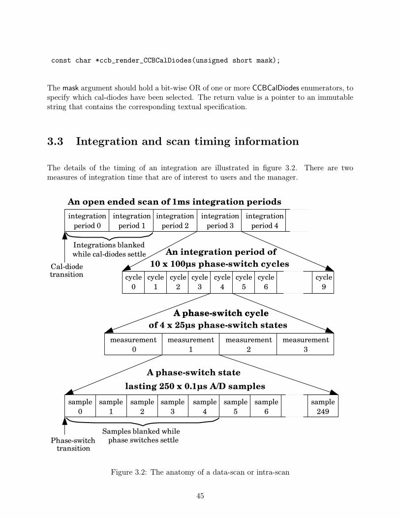
const char *ccb_render_CCBCalDiodes(unsigned short mask);
The mask argument should hold a bit-wise OR of one or more CCBCalDiodes enumerators, tospecify which cal-diodes have been selected. The return value is a pointer to an immutablestring that contains the corresponding textual specification.
3.3 Integration and scan timing information
The details of the timing of an integration are illustrated in figure 3.2. There are twomeasures of integration time that are of interest to users and the manager.
Figure 3.2: The anatomy of a data-scan or intra-scan
45

1. The integration-time, which is the total amount of time during which data are beingaccumulated in the integration-bin of a given phase switch state.
2. The integration-duration, which is the total amount of clock time that passes betweenthe start of one integration period and the start of the next.
The integration-time is shorter than the integration-duration, both because the latter has tobe split evenly between the separate integrations of different phase-switch bins, and becauseADC samples are blanked during phase-switch transitions.
3.3.1 Interval computations
Since the duration of a scan may exceed the number of 100ns clock ticks that will fit withinC’s unsigned long integer datatype, time intervals returned by functions in this section areexpressed using a pair of integers, one recording the number of full seconds in the interval,and the other containing the remaining nanoseconds. These integers are encapsulated withinthe CCBInterval datatype.
typedef struct { /* A time interval (t=sec+1.0e-9*ns) */
unsigned long sec; /* The number of complete seconds */
unsigned long ns; /* The remaining number of nano-seconds */
} CCBInterval;
On a computer that has 32-bit long integers, CCBInterval datatypes can hold time intervalsbetween 0ns and 136 years, with nano-second precision. Note however that the hardwareclock has a period of 100ns, so this sets the actual precision achievable.
The following functions are provided for manipulating intervals that are stored this way.
ccb scale interval()
The ccb scale interval() function returns the product of a time interval and an unsigned longinteger.
int ccb_scale_interval(CCBInterval *dt, unsigned long factor,
CCBInterval *ans);
A pointer to the time interval to be scaled is presented via the dt argument, the scale factoris specified via the factor argument, and the answer is recorded within the variable pointed
46

to by the ans argument. The ans argument and the dt argument can be pointers to the samevariable, in which case the answer will replace the original time interval within dt. Normallythe return value of the function is 0. If dt or ans are NULL, or the result overflows the hugebounds of the CCBInterval datatype, then errno is set accordingly, and the function returns1.
ccb add intervals()
The ccb add intervals() function computes the sum of two time intervals.
int ccb_add_intervals(CCBInterval *dt1, const CCBInterval *dt2,
CCBInterval *sum);
Pointers to the variables that contain the two intervals to be added, are passed via the dt1and dt2 arguments. The sum is assigned to the variable pointed to by the sum argument,which is allowed to be the same variable as that pointed to by dt1. Normally the returnvalue of the function is 0, but if any of the arguments are NULL, or the sum overflows thebounds of the CCBInterval datatype, then errno is set accordingly, and the function returns1.
ccb subtract interval()
The ccb subtract interval() function subtracts a small time interval from a larger time interval.
int ccb_subtract_interval(CCBInterval *dt1, CCBInterval *dt2,
CCBInterval *dif);
Normally ccb subtract interval() places the difference dt1 - dt2 in the dif argument and returnszero, but if the time interval being subtracted is greater than the interval that it is beingsubtracted from, or any of the arguments is NULL, dif is left unchanged, ccb subtract interval()returns 1 to indicate that an error occurred, and errno is set accordingly.
Note that dif and dt1 are allowed to point at the same variable, thus implementing theequivalent of dt1 -= dt2.
ccb compare intervals()
The ccb compare intervals() function compares two time intervals and returns an indicationof their ordering.
47
int ccb_compare_intervals(const CCBInterval *dt1,
const CCBInterval *dt2);
The return value is -1 if dt1 < dt2, 0 if dt1 == dt2, or 1 if dt1 > dt2.
ccb zero interval()
The ccb zero interval() function initializes a time interval to zero.
void ccb_zero_interval(CCBInterval *dt);
ccb interval is zero()
The ccb interval is zero() function returns non-zero if its argument denotes an interval of zeroseconds and zero nanoseconds.
int ccb_interval_is_zero(CCBInterval *dt);
ccb clock interval()
The ccb clock interval() function converts from a time expressed as a number of 100ns hard-ware clock ticks, to a time interval recorded in a CCBInterval datatype.
void ccb_clock_interval(unsigned long ticks, CCBInterval *dt);
The time interval that corresponds to the number of clock ticks in the ticks argument, isreturned in the variable pointed to by the dt argument.
3.3.2 Cal-diode and phase-switch settling times
At the start of some integrations, calibration-diodes and/or phase-switches change state, andthe effects on the detected signals take some time to settle. During this settling time, thehardware flags integrations that should be blanked by the off-line software. Similarly, duringeach phase-switch cycle, each change in the states of the phase switches, is followed by ADCsamples being discarded while the signals settle to their new values. The settling times of
48

the calibration-diodes potentially depends on whether they are being turned on or off, so inorder to compute the settling time, both before and after states of the diodes are needed.
The overall settling time of a given set of simultaneously commanded switch transitions, is themaximum of the settling times of the individual contributing transitions. This is calculatedby the ccb settling time() function, which takes the pre-transition and post-transition statesof the calibration diodes and phase-switches and returns the longest settling time of thesetransitions.
int ccb_settling_time(const CCBConfig *cnf,
unsigned prev_cal, unsigned next_cal,
unsigned prev_phs, unsigned next_phs,
CCBInterval *dt)
The cnf argument specifies the configuration of the CCB in the parent scan. The prev caland next cal arguments specify the pre-transition and post-transition states of the calibrationdiodes, expressed as bitwise unions of CCBCalDiodes enumerators, and the prev phs and next-phs arguments specify the pre-transition and post-transition states of the phase switches,expressed as bitwise unions of CCBPhaseSwitches enumerators. The dt argument should bea pointer to the CCBInterval variable in which to return the settling time.
The return value of ccb settling time() is normally 0, but if an error prevents the settlingtime from being computed, errno is set accordingly, and 1 is returned.
3.3.3 The number of phase-switch states per cycle
The total amount of time within an integration that is lost to phase-switch blanking, dependson the number of phase-switch states within a phase-switching cycle. This, as previouslyillustrated in figure 3.1, depends on how many phase-switches are configured to be switching,and can be calculated as:
measurements per cycle = 2nswitching (3.2)
Based on this equation, the ccb cycle length() function returns the number of phase-switchstates per cycle, corresponding to a particular value of the active switches argument of ccb-set phase switch cnf() (see page 29).
unsigned ccb_cycle_length(unsigned active_switches);
49

3.3.4 The physical duration of an integration period
The number of ADC samples per integration is the product of three terms; the numberof phase-switch cycles per integration (integ period), the number of phase-switch states perphase-switch cycle, as returned by ccb cycle length(), and the number of A/D samples perphase-switch state, given by the samp per state configuration parameter.
The ccb integration duration() function performs this calculation.
int ccb_integration_duration(const CCBConfig *cnf, CCBInterval *dt);
The cnf argument specifies the configuration of the CCB during the target scan, and theintegration period is returned in the variable pointed to by the dt argument.
The return value of ccb integration duration() is normally 0, but if an error prevents theintegration duration from being computed, errno is set accordingly, and 1 is returned.
3.3.5 The effective integration time
The actual amount of time per integration period that is spent integrating data, is less thanthe period between the start of one integration and the start of the next, due to the blankingof ADC samples during phase-switch transitions. The actual integration time per activephase-switch bin is calculated by the ccb integration time() function.
int ccb_integration_time(const CCBConfig *cnf, CCBInterval *dt);
The cnf argument specifies the configuration of the target scan, and the corresponding inte-gration time is returned in the variable pointed to by the dt argument.
The return value of ccb integration time() is normally 0, but if an error prevents the integra-tion time from being computed, errno is set accordingly, and 1 is returned.
3.3.6 The duration of a scan
The physical duration of a scan of a known number of integration periods is calculated bythe ccb scan duration() function. This function simply uses ccb scale interval() to multiplythe return value of ccb integration duration() by the specified number of integration periods.
int ccb_scan_duration(const CCBConfig *cnf,
50
unsigned long integrations,
CCBInterval *scan_dt);
The cnf argument specifies the configuration of the target scan. The integrations argumentspecifies the number of integrations within the scan, and the answer is returned in thevariable pointed to by the scan dt argument.
The return value of ccb scan duration() is normally 0, but if an error prevents the scanduration from being computed, 1 is returned, and the contents of scan dt are undefined.
3.3.7 The number of integrations that fit within a time interval
The number of complete integrations that will fit within a given time interval, along withthe remaining time of any final fractional integration, can be calculated with the ccb integ-per interval() function.
int ccb_integ_per_interval(const CCBConfig *cnf, CCBInterval *duration,
unsigned long *n, CCBInterval *rdt);
The cnf argument specifies the configuration of the target scan. The duration argumentspecifies the desired physical time-duration. The number of complete integrations that wouldfit into the specified time duration, is assigned to the variable pointed to by the n argument.The remaining time interval of any fractional final integration needed to reach the specifiedtime interval, is assigned to the rdt argument. Note that if the value returned in either ofthe n and rdt arguments is unneeded, the corresponding argument pointer can be passed asNULL.
The return value of ccb integ per interval() is normally 0, but if an error prevents the functionfrom completing successfully, 1 is returned, and the values of *n and *rdt become undefined.
3.3.8 The number of integrations in a calibration cycle
A single calibration cycle consists of up to CCB MAX NCAL calibration-diode states, witheach state being sustained for an integer number of integrations, as dictated by ccb set cal-diode cnf(). The ccb cal cycle length() function totals up the number of integrations spentin each of these states, and thus returns the number of integrations taken to perform a singlecalibration cycle.
int ccb_cal_cycle_length(const CCBConfig *cnf, unsigned long *ninteg);
51

The cnf argument specifies the configuration of the target scan, and the total number of inte-grations in a calibration-cycle is returned in the variable pointed to by the ninteg argument.
The return value of ccb cal cycle length() is normally 0, but if an error prevents the scanduration from being computed, 1 is returned, and the value of *ninteg is undefined.
3.4 Timestamps
There are various places where the date and time of an event need to be recorded andcommunicated with high accuracy. In particular every telemetry message includes a time-stamp which tells the manager when the corresponding event occurred. In both the serverand client libraries, these timestamps are exchanged in CCBTimeStamp structures.
typedef struct {
unsigned long mjd; /* The Modified Julian Day number */
unsigned long sec; /* The number of seconds into the day */
unsigned long ns; /* The number of nano-seconds into */
/* the specified second. */
} CCBTimeStamp;
The members of this structure are interpreted as follows.
• mjd
This is the date at which the telemetry message was assembled. The date is expressedin UTC, as a Modified Julian Day number. Specifically, this is the integer part of(Julian Date− 2400000.5).
• sec
This is the time of day at which the telemetry message was assembled, expressed asthe number of seconds that have passed since 0H UTC on the day indicated by themjd argument.
• ns
This is the number of nano-seconds that have elapsed since the start of the second thatis indicated by the sec parameter.
The following utility functions manipulate timestamps.
52
3.4.1 Zero-initializing a timestamp
The ccb zero timestamp() function sets all of the fields of a specified CCBTimeStamp variableto zero.
void ccb_zero_timestamp(CCBTimeStamp *ts);
3.4.2 Getting the current date and time
The ccb get timestamp() function returns the current date and time in a specified CCBTimeS-tamp structure.
int ccb_get_timestamp(CCBTimeStamp *t);
The current date and time are returned in the variable pointed to by the t argument. Thefunction normally returns 0, but on error returns 1 and sets errno accordingly.
3.4.3 Comparing two timestamps
The ccb compare timestamps() function compares the dates and times in two timestamps andreturns an indication of their ordering.
int ccb_compare_timestamps(CCBTimeStamp ta, CCBTimeStamp tb);
The return value of this function is -1, 0 or 1, depending on whether ta < tb, ta==tb, or ta> tb respectively.
3.4.4 Computing the amount of time remaining until a given time
The ccb time until() function returns the amount of time remaining until a specified time,returning a time-interval of zero if the time has already passed.
int ccb_time_until(CCBTimeStamp ts, CCBInterval *dt);
53

The time of the event of interest is passed in the ts argument, and the amount of timeremaining before that time is passed is returned in the variable pointed at by the dt argument.The returned interval is obviously out of date as soon as it is returned, and is thus of limiteduse. However it was written for the CCB simulator, in the ccbserver program, where theactual timing achieved isn’t critical.
3.4.5 Adding a time-interval to a timestamp
The ccb add to timestamp() function computes the timestamp of an event a given amountof time in the future of an existing timestamp.
int ccb_add_to_timestamp(const CCBTimeStamp *ta,
const CCBInterval *dt,
CCBTimeStamp *tb);
The existing timestamp should be in the value pointed at by the ta argument, and the time-interval to be added to this in the value pointed at by the dt argument. The addition ofthese two values is returned in the variable pointed at by the tb argument. Note that tb andta are allowed to point at the same variable.
3.4.6 Converting a time t value to a CCBTimeStamp value
The ccb time to timestamp() function takes a time t value returned by any of the functionsin the standard C library, plus a fraction of a second expressed in nanoseconds, and returnsthe CCBTimeStamp equivalent.
int ccb_time_to_timestamp(time_t t, unsigned long ns,
CCBTimeStamp *ts);
The result is returned in the variable pointed to by the ts argument. The return value ofccb time to timestamp() is normally 0, but if an error occurs, 1 is returned, and errno is setaccordingly.
3.4.7 Converting a CCBTimeStamp value to a time t value
The ccb timestamp to time() function takes a CCBTimeStamp value and converts it to astandard time t value, for use with functions in the standard C library, plus a remainder innanoseconds.
54

int ccb_timestamp_to_time(CCBTimeStamp ts, time_t *secs, unsigned long *ns);
The time t seconds part of the value is returned in the variable pointed to by the secsargument, and any remaining fractional part of the second, is assigned to the variable thatis pointed to by the ns argument, expressed as an integral number of nanoseconds.
The return value of ccb timestamp to time() is normally 0, but if an error occurs, 1 is returned,and errno is set accordingly.
3.4.8 Getting the clock-time from a timestamp
The ccb hms of timestamp() function, returns the clock-time of a timestamp in hours, min-utes and seconds.
void ccb_hms_of_timestamp(CCBTimeStamp ts, unsigned *hours,
unsigned *mins, unsigned *secs);
The clock-time is returned in the variables pointed to by the hours, minutes and secondsarguments.
3.5 Pseudo-random fake samples
In section 3.1.4 it was shown how the CCB can be configured to substitute fake, pseudo-random samples for real ADC samples. The pseudo-random sequence of fake samples isrestarted at the start of each integration period. This means that one can precisely predictwhat each sample of the integration period should be, and what the corresponding integrationsums should be. This section documents the functions and macros that are provided forcomputing what these values should be.
3.5.1 The values of integrated fake samples
In normal integration-mode, samples are directed alternately into one phase-switch bin ata time, according to the phase-switch configuration. Thus the sequence of fake samples issampled at different times by the different phase-switch bins, and the different bins thusend up with different values in them. The integrated values that should be found in eachof the phase-switch bins, at the end of every integration period, can be calculated by theccb fake integrations() function.
55

int ccb_fake_integrations(const CCBConfig *cnf,
unsigned long bins[CCB_NUM_PHASE_BINS]);
Since each CCB input port receives the same sequence of fake samples, this function reportsthe numbers that should be found in the integration bins of all of the input-ports.
The first argument must hold the configuration of the parent scan of the integrations. Ifsuccessful, the function returns 0, and places the predicted integrated values within the bins[]argument. This must be an array of one element per phase-switch bin, where the numberof phase-switch bins is parameterized by the constant, CCB NUM PHASE BINS, which isdefined as follows.
#define CCB_NUM_PHASE_BINS 4
The individual phase-switch bins are labeled by a 2-bit integer whose least-significant bit is1 if phase-switch A is closed, or 0 if phase-switch A is open, and whose most-significant bitis 1 if phase-switch B is closed, or 0 if phase-switch B is open. This integer is also used toindex the bins array. This is summarized in table 3.2.
Index Phase-switchesof bin B A0 open open1 open closed2 closed open3 closed closed
Table 3.2: The numeric labeling of phase-switch bins
3.5.2 The values of fake samples
The generation of fake samples relies on a 14-bit linear-feedback shift-register, which, at thestart of each clock-cycle, uses the current value of the register to compute its next value.The resulting sequence of numbers repeats every CCB FAKE CYCLE LENGTH samples, whereCCB FAKE CYCLE LENGTH is defined as:
#define CCB_FAKE_CYCLE_LENGTH ((1<<CCB_ADC_SAMPLE_SIZE)-1)
Given that CCB ADC SAMPLE SIZE is defined to be 14 (see section 5.7.3), CCB FAKE-CYCLE LENGTH has the value 16383. Each CCB FAKE CYCLE LENGTH samples are unique,and include every possible 14-bit number, except zero.
56

Since the sequence automatically repeats itself, the starting point of the sequence is arbitrary.The CCB chooses to start the sequence with all but the top-most of the 14 bits set to 1.The starting value of the sequence is thus parameterized as follows:
#define CCB_FIRST_FAKE_SAMPLE ((1<<(CCB_ADC_SAMPLE_SIZE-1))-1)
An implementation of the recurrence relation that computes the next sample in the sequencefrom its previous value, is provided in the form of a macro, in the CCB libraries, and is definedas follows:
#define CCB_NEXT_FAKE_SAMPLE(s) (CCB_ADC_SAMPLE_MASK & \
(((s)<<1) | (((((s)>>0)^((s)>>2)) ^ (((s)>>4)^((s)>>13))) & 1)))
The s argument of this macro must evaluate to an unsigned integral type of at least 2 bytes,and its evaluation must not have side-effects, since it is evaluated by the macro several times.Note that a macro was used, rather than a function, because the only uses of this featureto-date have used the macro in inner loops, where a function call would have added toomuch overhead. An example of using this is the following simple program that displays thesequence of fake values to the terminal.
#include <stdio.h>
#include <ccbcommon.h>
int main(int argc, char *argv[]) {
unsigned short s; /* The latest sample in the sequence */
int i;
/*
* Get the first sample of the sequence.
*/
s = CCB_FIRST_FAKE_SAMPLE;
/*
* Loop over and print the remaining samples of the sequence.
*/
for(i=0; i<CCB_FAKE_CYCLE_LENGTH; i++) {
/*
* Print the value of the current sample in the sequence.
*/
printf("Sample %5d: %hu\n", i, s);
/*
* Get the next sample in the sequence.
*/
s = CCB_NEXT_FAKE_SAMPLE(s);
57

}
return 0;
}
3.6 Physical status-monitoring and the front-panel LEDs
Parameters, such as power-supply voltages, that describe the physical state of the CCB, aremeasured and passed on to the CCB server by a general purpose I/O (GPIO) board. Thesame board is also used by the CCB server, and the ccb monitor status program, to controlmany of the front-panel LEDs. The CCB server acquires this monitoring information fromthe CCB GPIO device-driver as a CCBRawMonitorData structure.
typedef struct {
unsigned short fan12v; /* The voltage of the 12V fan */
/* power-supply */
unsigned short a8v; /* The voltage of the analog 8V supply */
unsigned short d5v; /* The voltage of the digital 5V supply */
unsigned short cnf_done; /* True if the FPGAs have all finished */
/* loading their firmware. */
unsigned short high_temp; /* True if there is a high-temperature */
/* condition. */
unsigned short ccb_id; /* The 2-bit ID of the CCB hardware */
CCBRawFpgaMonitorData fpga[CCB_NUM_FPGA];
/* Data of the master-FPGA CCB, */
/* followed by those of the 4 slave */
/* FPGAs. */
} CCBRawMonitorData;
In this structure, monitored analog values are represented by the integer counts that wereread from the corresponding analogue-to-digital converters of the GPIO card. These can beconverted to voltages using the CCB GPIO COUNTS TO VOLTS()macro (see section 4.11.1).
FPGA-specific monitoring information is recorded in the fpga[] member, wherein each CCBFPGA is represented by an element of the following type:
typedef struct {
unsigned short d1_2v; /* The voltage of the digital 1.2V PSU */
unsigned short d2_5v; /* The voltage of the digital 2.5V PSU */
unsigned short d3_3v; /* The voltage of the digital 3.3V PSU */
unsigned short a5v; /* The voltage of the analog 5V PSU */
unsigned short hb; /* The mean voltage of the heartbeat */
58

/* signal. */
unsigned short cnf_error; /* True if an error occurred while */
/* loading the FPGA firmware. */
unsigned short cnf_done; /* True if the FPGA firmware loading */
/* process has completed. */
} CCBRawFpgaMonitorData;
3.6.1 Monitor data calibration
The ccb calibrate monitor data() function can be used to convert all of the values in suchCCBRawMonitorData structures from ADC counts, to the corresponding floating-point mon-itor voltages. This function has the following prototype:
int ccb_calibrate_monitor_data(CCBRawMonitorData *raw,
CCBMonitorData *cal);
The first argument of this function is the object containing raw ADC counts. The secondargument is a pointer to where to place the corresponding values, after they have beenconverted to voltages. This has the CCBMonitorData data-type, which is described below.
If successful, this function returns 0. Otherwise it returns 1.
The CCBMonitorData data-type of the cal argument, is defined as follows.
typedef struct {
float fan12v; /* The 12V fan PSU voltage */
float a8v; /* The analog 8V PSU voltage */
float d5v; /* The digital 5V PSU voltage */
int cnf_done; /* True if all of the FPGAs have */
/* been programmed. */
int high_temp; /* True if the CCB enclosure is too hot */
int ccb_id; /* The 2-bit ID of the CCB */
CCBFpgaMonitorData fpga[CCB_NUM_FPGA]; /* Monitoring data for each */
/* FPGA, where index 0 refers to the */
/* master FPGA, and indexes 1-4 refer to */
/* the four slave FPGAs */
} CCBMonitorData;
Where CCB NUM FPGA is a macro that specifies the number of FPGAs in the CCB, includ-ing both the master and slave FPGAs. It is defined as:
59

#define CCB_NUM_SLAVE 4 /* The number of slave FPGAs */
#define CCB_NUM_FPGA (CCB_NUM_SLAVE+1) /* The total number of FPGAs */
The ccb id field reports the numeric ID that is associated with the cable-harness that isplugged into the front-panel of the CCB. Different cables are associated with the followingreceivers and locations, as shown in table 3.3. These associations are stored in the ccb ip-addresses file, which is installed in the CCB configuration directory.
Cable ID CCB computer Name IP address Association0 ccblab.gb.nrao.edu 192.33.116.144 The lab (or no cable)1 ccb1cm.gbt.nrao.edu 172.23.1.154 The 1cm receiver2 ccb3mm.gbt.nrao.edu 172.23.1.155 The 3mm receiver3 ccbspare.gb.nrao.edu 192.33.116.145 The spare lab cable
Table 3.3: The ID numbers of the CCB cables
The fpga array holds information that is specific to each FPGA in the, CCB, starting withthat of the master FPGA, followed by that of the CCB NUM SLAVE slave FPGAs. Eachelement provides monitoring information for one FPGA, and is defined as follows.
typedef struct {
float d1_2v; /* The digital 1.2V PSU voltage */
float d2_5v; /* The digital 2.5V PSU voltage */
float d3_3v; /* The digital 3.3V PSU voltage */
float a5v; /* The analog 5V PSU voltage */
float hb; /* The mean heartbeat voltage */
int cnf_error; /* True if the FPGA the firmware failed */
/* the checksum test. */
int cnf_done; /* True if the FPGA is programmed */
} CCBFpgaMonitorData;
Note that the contents of CCBMonitorData objects can be displayed on stdout by calling theccb display monitor data() function. This has the following prototype:
int ccb_display_monitor_data(CCBMonitorData *cal);
If successful, this function returns 0. Otherwise it returns 1.
3.6.2 Computing the states of the front-panel status LEDs
There are two groups of LEDs that can be controlled by software in the CCB. The firstgroup is meant to summarize important aspects of the monitoring values received from
60

the GPIO card. Thus, to facilitate programs that use the monitoring values received inCCBRawMonitorData objects, to set the states of these LEDs, the ccb compute led states()function can be called to determine which of these LEDs should be turned on, and whichshould be turned off.
int ccb_compute_led_states(CCBRawMonitorData *raw,
int *light, int *snuff);
If this function is successful, it returns 0, and assigns bit-mask of the LEDs that are tobe turned on, and turned off, respectively to the *light and *snuff arguments. Each of theLEDs is represented by a single bit, which has the value assigned to it by the CCBPanelLedenumeration.
typedef enum {
CCB_SAMPLE_MODE_LED = 1, /* CCB is in sample mode */
CCB_SLAVE4_READY_LED = 2, /* Slave-FPGA 4 firmware loaded */
CCB_SLAVE3_READY_LED = 4, /* Slave-FPGA 3 firmware loaded */
CCB_SLAVE2_READY_LED = 8, /* Slave-FPGA 2 firmware loaded */
CCB_SLAVE1_READY_LED = 16, /* Slave-FPGA 1 firmware loaded */
CCB_MASTER_READY_LED = 32, /* Master-FPGA firmware loaded */
CCB_HEARTBEATS_OK_LED = 64, /* All FPGAs have healthy heartbeats. */
CCB_POWER_OK_LED = 128, /* All power-supllies ok */
CCB_SLAVE4_ERROR_LED = 256, /* Slave-FPGA 4 firmware load-error */
CCB_SLAVE3_ERROR_LED = 512, /* Slave-FPGA 3 firmware load-error */
CCB_SLAVE2_ERROR_LED = 1024,/* Slave-FPGA 2 firmware load-error */
CCB_SLAVE1_ERROR_LED = 2048,/* Slave-FPGA 1 firmware load-error */
CCB_MASTER_ERROR_LED = 4096,/* Master-FPGA firmware load-error */
CCB_CAL_MODE_LED = 8192, /* Cal test-mode */
CCB_DUMP_MODE_LED = 16384, /* Dump mode */
CCB_TEST_MODE_LED = 32768 /* Test mode */
} CCBPanelLed;
The commands to turn on and turn off the specified sets of LEDs are sent to the GPIO card,as CCB GPIO IOCTL LIGHT LEDS and CCB GPIO IOCTL SNUFF LEDS ioctl() commands.This is documented, along with other details of the CCB GPIO-card device-driver in aseparate document, titled “The CCB gpio-104 device-driver”.
3.6.3 Computing the states of the front-panel mode LEDs
The other group of software-controllable front-panel LEDs is meant to indicate the currentobserving modes, such as the type of the current scan or intra-scan. The sets of LEDs tolight or extinguish can be computed by calling the ccb compute mode led states() function.
61

int ccb_compute_mode_led_states(const CCBConfig *cnf,
CCBScanType type,
int *light, int *snuff);
The first argument specifies the configuration of the current scan. The second, which specifiesthe type of the current scan, must be a CCBScanType enumerator, as defined below. Thelight and snuff arguments must be pointers to the integer variables, to which the sets of LEDsto light and extinguish should be assigned.
typedef enum {
CCB_NORMAL_SCAN, /* A normal observing scan */
CCB_INTRA_SCAN, /* An intra-scan */
CCB_DUMP_SCAN /* A dump-mode scan */
} CCBScanType;
As mentioned previously, the commands to turn on and turn off the specified sets of LEDs aresent to the GPIO card, as CCB GPIO IOCTL LIGHT LEDS and CCB GPIO IOCTL SNUFF-LEDS ioctl() commands, as documented in a separate document, titled “The CCB gpio-104device-driver”.
62
Chapter 4
The CCB manager communicationsAPI
The following sections describe the functions that the CCB communications library providesfor use by the manager. The following illustrates a typical time sequence of function callsfor a single-threaded manager.
1. Create the object needed to talk to a CCB server:
char errmsg[CCB_MAX_LOG];
CCBClientLink *cl = new_CCBClientLink(sizeof(errmsg), errmsg);
if(!cl) {
fprintf(stderr, "%s\n", errmsg);
exit(1);
}
2. Create a CCB configuration object:
CCBConfig *cnf = new_CCBConfig();
if(!cnf)
return ERROR;
3. Tell the CCBClientLink object how to deliver log messages:
if(ccb_log_msg_callback(cl, ...))
return ERROR;
4. Install message-received callback functions:
if(ccb_cmd_error_callback(cl, ...) ||
ccb_status_reply_callback(cl, ...) ||
ccb_integ_msg_callback(cl, ...) ||
ccb_monitor_msg_callback(cl, ...))
return ERROR;
63
5. Initiate a non-blocking connection to a CCB server:
if(ccb_client_connect(cl, host, 1))
return ERROR;
6. Load the CCB device driver
if(ccb_queue_load_driver_cmd(cl, id, CCB_NORMAL_DRIVER))
return ERROR;
7. Set up the initial CCB configuration:
if(ccb_set_phase_switch_cnf(cnf, ...) ||
ccb_set_cal_diode_cnf(cnf, ...) ||
ccb_set_timing_cnf(cnf, ...) ||
ccb_set_sampler_cnf(cnf, CCB_ADC_SAMPLES))
return ERROR;
8. Enable all telemetry streams
if(ccb_queue_telemetry(cl, id, CCB_ALL_STREAMS))
return ERROR;
9. Queue the first start-scan command:
if(ccb_queue_start_scan_cmd(cl, id, cnf, ...))
return ERROR;
10. Now invoke the manager’s event loop:
while(!shutdown_requested) {
fd_set rfds; /* The set of file-descriptors to watch */
/* for readability */
fd_set wfds; /* The set of file-descriptors to watch */
/* for writability */
int nready; /* The number of file descriptors ready */
/* for I/O. */
int maxfd; /* The maximum of the file descriptors in */
/* ’rfds’ and ’wfds’. */
/*
* Clear the file-descriptor sets.
*/
FD_ZERO(&rfds);
FD_ZERO(&wfds);
maxfd = 0;
/*
* Add the file-descriptors that the library wants us to watch,
* to rfds and wfds.
*/
if(ccb_client_select_args(cl, &rfds, &wfds, &maxfd))
return ERROR;
/*
64

* Wait indefinitely for the specified I/O events.
*/
nready = select(maxfd+1, &rfds, &wfds, NULL, NULL);
/*
* Error?
*/
if(nready < 1)
return ERROR;
/*
* Perform the types of I/O indicated by select().
*/
else if(ccb_client_communicate(cl,
ccb_client_selected_io(cl, &rfds, &wfds)))
return 1;
}
11. Disconnect from the current CCB server:
ccb_client_disconnect(cl);
12. Reclaim the CCB communication resources:
cl = del_CCBClientLink(cl);
As documented later, note that when ccb client communicate() receives messages, it calls theappropriate callback function from the callbacks that were registered in step 4, to deliverthese messages to the manager.
4.1 Include files
The datatype-declarations, function-prototypes and constants of the public API of the CCB-client communications-library are contained in the following include files.
• ccbclientlink.h
This header-file contains all of the public function-prototypes and datatype declarationsthat are specific to the client side of the communications link.
• ccbcommon.h
This header-file contains the public function-prototypes and datatype declarations thatare shared between the client and server communications libraries. It need not beincluded explicitly by the client code, since it is already included by ccbclientlink.h.
• ccbconstants.h
65

This header-file contains all of the constants that affect the operation of the commu-nications link. It need not be included explicitly by client code, since it is alreadyincluded by ccbcommon.h.
4.2 The CCB-client communications library
The library that implements the CCB client-communications API, is a shared library calledlibccbclientlink.so. Under Solaris and Linux, this filename is actually a symbolic link to themost recent version of the library.
Among other advantages, the use of a shared library rather than a static library has thebenefit, at least under Solaris and Linux, of allowing one to restrict which symbols areexported into the name-space of the application. This not only prevents programs fromusing unstable private interfaces, but also greatly reduces name-space pollution and thepossibility of symbol-name clashes.
Linking a C program with this library under either Linux or Solaris can be done as follows.
gcc -o foo *.o -lccbclientlink
Note that linkage instructions built into the shared library cause other required libraries,such as -lsocket under Solaris, to be linked automatically.
4.3 Creating the client resources needed to talk to a
CCB server
All of the resources that are needed to communicate with a remote CCB server are encap-sulated within an opaque CCBClientLink object. Each instance of a CCBClientLink objectis capable of communicating with a single CCB server at a time, so to simultaneously talkto multiple CCB servers, multiple CCBClientLink objects must be created, with one objectassigned to each server. Alternatively, if only one backend is to be controlled/monitoredat a time, a single CCBClientLink object can initially be connected to one CCB server, andthen later be connected to a different CCB server. To create a CCBClientLink object, it isnecessary to call new CCBClientLink().
CCBClientLink *new_CCBClientLink(size_t errdim, char *errmsg);
If successful, this function allocates and returns a pointer to an opaque CCBClientLink object.This object should thereafter be passed to all other CCB communications-library functions.
66
Note that this function does not itself initiate a connection to a CCB server. That is therole of the ccb client connect() function, which will be described below.
On error new CCBClientLink() returns NULL, and places an error message in the buffer thatis pointed to by the errmsg argument. The allocated size of this buffer must be specified inthe errdim argument, such that if the length of an error message exceeds errdim-1 characters,it can be truncated to fit. If truncation is necessary, and errdim is greater than 0, a ’\0’terminator is placed in errmsg[errdim-1].
If new CCBClientLink() returns successfully, subsequent errors detected by library functionsare reported as log messages. If this happens before the manager has got around to callingccb log msg callback() to tell the library how to deliver log messages, the error message isdisplayed to the local stderr. Thus, to ensure that all log messages get recorded for posterity,it is important that the manager call ccb log msg callback() as soon as possible after new-CCBClientLink() returns.
4.4 Connecting to a CCB server
The ccb client connect() function initiates a pair of connections to the control and telemetryports of the CCB server.
int ccb_client_connect(CCBClientLink *cl, const char *host,
int nonblocking);
The cl argument must be an object previously returned by new CCBClientLink(). If thisobject is already connected to a CCB server, the existing connection is terminated beforethe new one is initiated.
The value of the host argument should contain the numeric or textual IP address of thetarget CCB server.
The nonblocking argument specifies whether ccb client connect() should initially place thecontrol and telemetry sockets in non-blocking I/O mode. Note that after ccb client connect()returns, the manager can toggle the non-blocking behavior of the sockets by calling ccb client-non blocking io().
If the nonblocking argument is zero, blocking socket I/O is used, and ccb client connect()doesn’t return until it has either established both the control and telemetry connections, oran error occurs.
Alternatively, if the nonblocking argument is non-zero, ccb client connect() may not get anyfurther than initiating the connections before returning. Watching for the completion of
67

the connections is left to subsequent calls to ccb client communicate(), in response to I/Oactivity detected by the manager’s event loop.
Note that regardless of the value of the nonblocking argument, if the host argument containsa textual address, ccb client connect() blocks the caller while it queries a name server forthe corresponding IP address. This is due to the non-existence of a non-blocking interfaceto query name-servers. As such, if non-blocking behavior is required, it is best to supply anumeric IP address in the host argument.
If ccb client connect() detects an error, it returns non-zero. Otherwise it returns 0 to indicatesuccessful connection initiation. When using blocking I/O, a successful return-value indicatesthat both the telemetry and control connections have been completed successfully.
4.5 Disconnecting from a CCB server
The ccb client disconnect() function terminates the telemetry and control connections of aCCBClientLink object.
void ccb_client_disconnect(CCBClientLink *cl);
If no connection is currently established, ccb client disconnect() does nothing. This functionis called internally by ccb client connect() before initiating a new connection, and also bydel CCBClientLink() before deleting a CCBClientLink object, so the manager probably won’tneed to call it explicitly.
4.6 Deleting a redundant CCBClientLink object
Once a CCBClientLink object is no longer needed, its resources can be returned to the systemby calling the del CCBClientLink() function.
CCBClientLink *del_CCBClientLink(CCBClientLink *cl);
This function both shuts down any CCB server connection associated with the specifiedCCBClientLink object, and returns all dynamically allocated resources, associated with theobject, to the system. The function always returns NULL. This allows the caller to type:
CCBClientLink *cl;
...
cl = del_CCBClientLink(cl);
68

This sets the invalidated cl pointer variable to NULL, such that if any statement subse-quently tries to access the deleted object through this pointer, it is rewarded with a tell-talesegmentation fault, rather than producing unpredictable behavior.
4.7 Requesting non-blocking I/O
To prevent network congestion from blocking the manager process, when it could be doingother things, the ccb client non blocking io() function allows the manager to place the clientsockets into non-blocking I/O mode. Note that this is redundant if the nonblocking argumentof new CCBClientLink() was non-zero when the CCBClientLink object was created.
int ccb_client_non_blocking_io(CCBClientLink *cl, int on);
This turns on non-blocking I/O when the on argument is non-zero, or turns it off when theon argument is zero. On error, this function sets errno appropriately and returns non-zero.Otherwise it returns zero to indicate success.
Used in conjunction with select() or poll() to perform I/O multiplexing, non-blocking I/Oallows the manager to do other things during network congestion.
In a multi-threaded manager this function should not be called when any other threads mightbe reading from or writing messages to the CCB control and/or telemetry sockets.
4.8 ccb client communicate() – Perform client socket
I/O
The ccb client communicate() function is responsible for all socket-level I/O over the controland telemetry links. According to the contents of its io argument, it incrementally sendspreviously queued outgoing control messages, receives incoming control-link replies, and/orreceives incoming telemetry messages.
int ccb_client_communicate(CCBClientLink *cl, unsigned io);
When non-blocking I/O is selected, the io argument, which tells ccb client communicate()which forms of I/O to attempt, must contain a value returned by either ccb selected io()or ccb polled io(), which are documented below. Alternatively, when blocking I/O has beenselected, and ccb client communicate() is being called separately by different threads, the
69

value of the io argument within a given thread must be chosen according to the type of I/Othat that thread has been given responsibility for, as described shortly.
The return value of ccb client communicate() is normally 0, but if an error occurs, errno isset accordingly, and a non-zero value is returned.
4.9 Client I/O multiplexing
The client communications library expects to be told by the manager whenever I/O that itwants to perform can be done. It assumes that the manager is either using an event loopbased on functions like select() or poll() to watch for the readability or writability of thelibrary’s sockets, or that it is devoting multiple threads to perform blocking I/O on thesesockets. Since only the library knows which types of I/O it wants the manager to watch for,it provides facilities for keeping the manager informed of this.
The following subsections describe the facilities provided for different I/O multiplexing op-tions.
4.9.1 Using the select() system call
When using select() to watch for I/O, the manager should use the ccb client select args()function to augment the contents of the arguments that are to be passed to select(), accordingto the needs of the manager’s CCBClientLink object.
int ccb_client_select_args(CCBClientLink *cl, fd_set *rfds,
fd_set *wfds, int *maxfd);
On input, the rfds argument is a pointer to an existing set of the file descriptors that thecaller wants select() to watch for readability. Similarly the wfds argument is a pointer to anexisting set of the file descriptors that the caller wants to watch for writability. Finally themaxfd argument is a pointer to a variable that contains the maximum of all file descriptorsthat the caller has placed in rfds and wfds. On return, rfds and wfds are augmented with thefile descriptors that *cl wants to have watched, and if any of these descriptors exceeded theinput value of *maxfd, it is updated accordingly. Normally this function returns 0, but onerror it returns non-zero.
Note that when subsequently passing these arguments to select() the first argument of select()should be *maxfd + 1.
After select() returns, the sets of file descriptors that it found to be readable and/or writablecan be converted to the form required by the io argument of ccb client communicate() by
70

calling ccb client selected io().
unsigned ccb_client_selected_io(CCBClientLink *cl,
const fd_set *rfds,
const fd_set *wfds);
The rfds and wfds arguments are pointers to the sets of file descriptors that select() indicatedwere readable and writable, respectively. The return value is the value to pass to ccb client-communicate() to tell it what types of I/O to attempt.
4.9.2 Using the poll() system call
When using poll() to watch for I/O, the manager should use the ccb client poll args() functionto augment the contents of the arguments that poll() requires, according to the forms of I/Othat the manager’s CCBClientLink object is awaiting.
int ccb_client_poll_args(CCBClientLink *cl, int size,
struct pollfd *fds, int *nfds);
The fds argument is an array of dimension size, in which *nfds elements at the start of thearray are occupied. ccb client poll args() adds up-to two socket file descriptors to this array,and increments *nfds accordingly. Note that size - *nfds must be at least 2. Normally thisfunction returns 0, but on error it returns non-zero.
After poll() subsequently returns, the sets of file descriptors that it found to be readableand/or writable can be converted to the form required by the io argument of ccb client-communicate() by calling ccb client polled io().
unsigned ccb_client_polled_io(CCBClientLink *cl,
const struct pollfd *fds,
int nfds);
The fds argument is the array in which ccb client poll args() placed its file descriptors, andpoll() subsequently flagged I/O events, and the nfds argument is the number of occupiedelements within this array. The return value is the value to pass to ccb client communicate()to tell it what types of I/O to attempt.
71

4.9.3 Third party event handlers
When using an event handler which hides the call to select() or poll() behind a customAPI, the above functions clearly aren’t sufficient. To cope with this more general case, theCCB communications library allows the application to register an optional callback function,which the library calls whenever the library’s socket file descriptors change, and wheneverthe I/O events that the event handler should be watching these sockets for, change.
The CCB CLIENT SOCKETS FN macro should be used for the declarations and prototypesof suitable callback functions, and the CCBClientSocketsFn typedef can be used for recordingpointers to them.
#define CCB_CLIENT_SOCKETS_FN(fn) int (fn)(CCBClientLink *cl, \
void *data, int cntrl_sock, int telem_sock, unsigned io)
typedef CCB_CLIENT_SOCKETS_FN(CCBClientSocketsFn);
int ccb_client_sockets_callback(CCBClientLink *cl,
CCBClientSocketsFn *fn,
void *data);
The callback function is registered via the fn argument of ccb client sockets callback(), andany application-specific resources to be passed to the callback are specified via the dataargument.
The cntrl sock and telem sock arguments of the callback function report the socket file de-scriptors associated with the control and telemetry links, respectively. When one or both ofthese links is not connected, the corresponding file descriptor is reported as -1. The set of I/Oevents that the event handler should watch these sockets for, is specified in the io argumentof the callback function, expressed as a bitwise union of CCBClientIOStatus enumerators.
typedef enum {
CCB_CNTRL_READ = 1, /* Readability of the control socket */
CCB_CNTRL_WRITE = 2, /* Writability of the control socket */
CCB_TELEM_READ = 4, /* Readability of the telemetry socket */
CCB_TELEM_WRITE = 8 /* Writability of the telemetry socket */
} CCBClientIOStatus;
Subsequently, when the application’s event handler reports any of the specified events, themanager should call the ccb client communicate() function with an io argument that is thebitwise union of the CCBClientIOStatus enumerators that denote the events that were de-tected.
72
4.9.4 Using threads to multiplex I/O
In a threaded program, provided that blocking I/O is selected, one thread should be devotedto reading from the control socket, another to writing to the control socket, and a third toreading from the telemetry socket. First a connection must be established by calling ccb-client connect() with its nonblocking argument specified as 0. Then each of the three threadsmust call ccb client communicate() with a different one of the following 3 CCBClientIOStatusenumerators as the value of its io argument.
• CCB CNTRL READ
Read messages from the control link until either an error occurs, of the control link isterminated.
• CCB CNTRL WRITE
Repeatedly wait for and write queued messages to the control link until either an erroroccurs or the control link is terminated.
• CCB TELEM READ
Read messages from the control link until either an error occurs, of the telemetry linkis terminated.
Note that in each case, ccb client communicate() doesn’t return until either an error occurs,or the control link is terminated.
4.10 Registering a command-error callback function
Whenever the CCB server receives a command message from the manager, over the controllink, it examines the contents of the message, then sends back an acknowledgment reply toreport whether any problems were encountered. When the ccb client communicate() functionreceives one of these acknowledgments, if the message says that the command had a problem,ccb client communicate() calls an error-reporting callback function provided by the manager.To register this callback function, the manager calls ccb cmd error callback().
The CCB CMD ERROR FN macro should be used for the declarations and prototypes of suit-able callback functions, and the CCBCmdErrorFn typedef can be used for recording pointersto them.
#define CCB_CMD_ERROR_FN(fn) int (fn)(CCBClientLink *cl, \
void *data, long id, \
CCBCmdStatus status)
73
typedef CCB_CMD_ERROR_FN(CCBCmdErrorFn);
int ccb_cmd_error_callback(CCBClientLink *cl, CCBCmdErrorFn *fn,
void *data);
The callback function is registered via the fn argument of ccb cmd error callback(), and anyapplication-specific resources to be passed to the callback are specified via the data argument.The id argument of the callback function is passed the value of the message identifier that wasspecified when the problematic command was queued by the manager. The status argumentof the callback is used to report coarse information about the error.
typedef enum {
CCB_CMD_ACCEPTED, /* This enumerator isn’t forwarded to error */
/* callbacks */
CCB_CMD_GARBLED, /* The contents of the command message */
/* were invalid and couldn’t be fixed. */
CCB_CMD_IGNORED, /* The command didn’t make sense at this */
/* time, and was ignored. */
CCB_CMD_SYSERR /* An unexpected internal software or */
/* hardware error was encountered while */
/* attempting to execute the command. */
} CCBCmdStatus;
This enumeration is in the public header-file of the communication library, so to prevent ABIproblems if new error conditions are added, and somebody forgets to recompile either thelibrary, the CCB server, or the manager, new error enumerators should always be appendedto the end of the enumeration, rather than inserted, and old enumerators should not beremoved or re-ordered. With this caveat, if functions that use values from this enumerationare prepared to handle values that they don’t know about, at worst an unknown errorcondition will elicit a warning, rather than, say accessing a non-existent element in an arrayof error conditions, or associating the incorrect error condition with an enumerator.
Note that the reported error conditions aren’t meant to be very precise. For more detailedinformation, the maintainer should look at the corresponding log messages that the CCBserver sends to the manager via the telemetry connection. As such, it is hoped that few,if any, new enumerators will need to be added. In practice, after debugging the managerand the server, the only error that should be expected during normal operations should beCCB CMD SYSERR, which will be sent if a hardware failure is detected. As such, addingmore finely targeted error conditions seems pointless, especially given that there isn’t muchthat the manager can do in response, other than report which command evoked the errormessages that appear in the log, and perhaps attempt a CCB reset.
74

4.11 Outgoing CCB commands
The following two sections describe the control commands that are sent to the CCB serverover its control link. The functions that queue each of these commands, all take the sametwo initial arguments, which are interpreted as follows.
1. A pointer to the CCBClientLink object that identifies the remote backend that thecommand is to be sent to.
2. An arbitrary manager-chosen integer message-identifier to be passed to the applica-tion’s error callback in the event that the CCB server encounters problems with thiscommand. This could, for example, be a manager-defined message-type enumerator,or the value of a command sequence-counter.
4.11.1 Outgoing CCB control commands
This section describes the public functions that are used to queue CCB control commands,for subsequent dispatch to the CCB server when ccb client communicate() is called.
Each of these functions returns an integer, which is 0 on success and non-zero otherwise.On failure, which could, for example, be due to running out of memory to queue the newmessage, or due to the manager passing invalid arguments, errno is set accordingly.
A summary of the available commands is given in the following table, along with the namesby which they are referred to elsewhere in the text.
Name Descriptionstart-scan Start a new scan at the end of the current integrationstop-scan Start a new intra-scan ASAPdump-scan Start a new dump-mode scan ASAPload-driver Load either the real or the simulation device-driver.reset Re-initialize the hardware.ping Request a link-verification reply.status-request Request a CCB-status report.shutdown Shutdown the real-time CPU.reboot Reboot the real-time CPU.monitor Configure monitoring.telemetry Configure the telemetry streams.logger Configure the message logger.set-dacs Set the misc analog outputs of the GPIO card.
75

ccb queue start scan cmd() – Queuing a start-scan command
The start-scan command causes a new scan, with a specified configuration, to be started onthe 1-second boundary that is specified by the mjd and tod parameters. The accuracy withwhich the CCB can start the scan at the specified time, depends on how far in advance thestart-scan command is sent. There are three possibilities:
1. Ideally, the start-scan command should be timed to arrive more than one second beforethe requested time. If it does, then the device driver will tell the CCB hardware aboutthe command, from its 1PPS interrupt handler, precisely one second in advance of therequested start time, telling it to start the scan at the next 1 second tick. This willthen give the hardware one second to halt the previous scan, finish sending its data tothe CPU, reconfigure itself for the new scan, and finally be ready and waiting to startthe next scan, before the specified 1-second tick.
Note that in this case, the scan should start at the specified time, regardless of thestatus of any previously running scan.
2. Less ideally, if the start-scan command arrives less than or equal to one second beforethe requested start time, then the device-driver in the computer will wait for the next1-second interrupt, before telling the hardware about the command. It will then tellthe hardware to start the new scan as soon as possible, without synchronizing with a1-second tick.
In this case, the actual start time will be delayed slightly, with respect to specified 1-second boundary, both by software latencies, and by the time needed by the hardwareto halt the previous scan, finish sending any half sent data-frame to the computer, andreconfigure the hardware for the new scan.
If the previous scan was a normal observing scan, then at worst, the time needed bythe hardware to shutdown the previous scan and start the next will be much less than1µs, and the startup delay will thus be dominated by software latencies within thecomputer.
On the other hand, if the previous scan was a dump-mode scan, then the time neededby the hardware to shutdown the previous scan and start a new one could be as muchas 32ms, and this should dominate the startup delay.
3. Finally, if the start-scan command is received after the requested time, then the newscan will be started as soon as possible, just like a stop-scan command, without anyattempt to synchronize it to a 1 second boundary.
start-scan commands are sent by first calling ccb queue start scan cmd() to queue the com-mand for dispatch, then subsequently calling ccb client communicate() to send it to the CCBserver.
76
int ccb_queue_start_scan_cmd(CCBClientLink *cl, long id,
const CCBConfig *cnf,
unsigned long scan,
unsigned long mjd,
unsigned long tod);
The arguments of this function are interpreted as follows.
• The configuration of the CCB during the new scan
This argument specifies the behavior of the CCB during the requested scan. It musthave been previously allocated by calling new CCBConfig(), with any changes from thedefault configuration having been established by calling the ccb set * cnf() functionsdescribed earlier in this document.
• A numeric ID to give the scan
This is a manager-chosen numeric identifier, which is thereafter transmitted along withthe data of each integration of the new scan.
• The date at which to start the scan (mjd)
This is the date at which the scan should be started, expressed in UTC, as a ModifiedJulian Day number. To be precise, this is the integer part of (Julian Date−2400000.5).
• The time-of-day at which to start the scan (tod)
This is the time of day at which the scan should be started, specified as the integernumber of seconds after 0H UTC on the day indicated by mjd. The scan starts at thestart of the specified second, provided that the command is received at more than onesecond in advance of this time.
ccb queue stop scan cmd() – Queuing a stop-scan command
This operates like the start-scan command, except that on receipt by the server, a new scan isstarted as quickly as possible, rather than waiting for a specified 1-second tick. The resultingtruncated integration from the previous scan is discarded.
Note that although this command starts a new scan, it is called stop-scan because it stopsan observing scan. The scan that it then starts, which can usefully be referred to as anintra-scan, is basically a scan that is used only for monitoring purposes, and is not recordedin the observer’s FITS file.
A stop-scan command is sent by first calling ccb queue stop scan cmd() to queue the com-mand for dispatch, then subsequently calling ccb client communicate() to send it to the CCBserver.
77
int ccb_queue_stop_scan_cmd(CCBClientLink *cl, long id,
CCBConfig *cnf,
unsigned long scan);
The arguments of this function are interpreted as follows.
• The configuration of the CCB during the new intra-scan
This argument specifies the behavior of the CCB during the requested intra-scan thatfollows the stop command. It must have been previously allocated by calling new-CCBConfig(), with any changes from the default configuration having been establishedby calling the ccb set * cnf() functions described earlier in this document.
• A numeric ID to give the scan
This is a manager-chosen numeric identifier, which is thereafter transmitted along withthe data of each integration of the new intra-scan.
ccb queue dump scan cmd() – Queuing a dump-scan command
This operates like the stop-scan command, except that instead of the integrated data of theresulting intra-scan being sent back to the manager, the raw 100ns samples of a specifiedADC are sent to any client that is connected to the dump-mode port of the CCB server.
Since the bandwidth of the USB link between the master FPGA and the real-time computerisn’t high enough to sustain continuous readback of ADC samples, only a specified numberof samples are collected from the start of each integration.
A dump-scan command is sent by first calling ccb queue dump scan cmd() to queue the com-mand for dispatch, then subsequently calling ccb client communicate() to send it to the CCBserver.
int ccb_queue_dump_scan_cmd(CCBClientLink *cl, long id,
CCBConfig *cnf,
unsigned long scan,
unsigned short adc,
unsigned long samples,
unsigned long frames);
The arguments of this function are interpreted as follows.
• The configuration of the CCB during the dump-scan (cnf)
78
This argument specifies the behavior of the CCB during the requested intra-scan thatthe dump command starts. It must have been previously allocated by calling new-CCBConfig(), with any changes from the default configuration having been establishedby calling the ccb set * cnf() functions described earlier in this document.
• A numeric ID to give the scan
This is a manager-chosen numeric identifier, which is thereafter transmitted along withthe dumped data and the monitor data of each integration of the intra-scan.
• The digitizer whose samples are to be collected (adc)
This specifies which ADC channel is to have its raw samples siphoned off to be sentto the CCB computer. This must be a number between 0 and CCB NUM ADC−1,where CCB NUM ADC, which is defined as follows, in ccbconstants.h, parameterizesthe number of digitizers in the CCB.
#define CCB_NUM_ADC 16
• The maximum number of samples to collect per integration (samples)
The number of 100ns ADC samples that can be collected and dispatched to the CCBcomputer at the start of each integration, is limited by the size of the frame-buffer in theCCB’s master FPGA. If fewer samples than the hard-limit are desired per integration,then this argument can be used to specify a smaller number. Otherwise the argumentcan be specified as CCB DUMP MAX SAMPLES, which is a macro that parameterizesthe maximum number of samples that can be acquired per integration period. This isdefined as follows.
#define CCB_FPGA_FIFO_WORD_SIZE 16384 /* 16-bit words */
...
#define CCB_DUMP_MAX_SAMPLES (CCB_FPGA_FIFO_WORD_SIZE-1)
Where CCB FPGA FIFO WORD SIZE denotes the actual size of the FIFO that imple-ments the firmware frame-buffer.
Note that if the samples argument specifies more samples than can actually be accu-mulated, the result will be as though CCB DUMP MAX SAMPLES had been specified.
• The maximum number of integrations to dump (frames)
At the start of each new integration of a dump-scan, data are collected and sentto the CCB computer. This argument specifies how many of these per-integrationdata-frames are to be sent, per scan, to remote dump-mode clients. A value of zero,as parameterized by the macro CCB DUMP ALL FRAMES, specifies that data-framesshould be delivered indefinitely.
#define CCB_DUMP_ALL_FRAMES 0
79

ccb queue load driver cmd() – Queuing a load-driver command
Load either the real CCB device driver, or the CCB simulation device driver.
typedef enum {
CCB_NORMAL_DRIVER, /* The real CCB device-driver */
CCB_VIRTUAL_DRIVER /* The CCB simulation device-driver */
} CCBDriverType;
int ccb_queue_load_driver_cmd(CCBClientLink *cl, long id,
CCBDriverType type);
ccb queue monitor cmd() – Queuing a monitor command
monitor commands specify how frequently messages containing monitoring should be sent tothe manager over the telemetry stream.
int ccb_queue_monitor_cmd(CCBClientLink *cl, long id,
unsigned short period);
The arguments of this function are interpreted as follows.
• The monitoring period (period)
This argument specifies the interval between monitoring updates, expressed as an in-teger multiple of the integration period.
ccb queue telemetry cmd() – Queuing a telemetry command
telemetry commands specify which telemetry streams are to be sent to the manager. Atelemetry command is sent by first calling ccb queue telemetry cmd() to queue the commandfor dispatch, then subsequently calling ccb client communicate() to send it to the CCB server.
int ccb_queue_telemetry_cmd(CCBClientLink *cl, long id,
unsigned short streams);
The arguments of this function are interpreted as follows.
80

• The telemetry data-stream selection (streams)
This parameter contains a bit-wise union of CCBTelemetryStream enumerators, speci-fying which streams should be sent to the manager.
typedef enum {
CCB_INTEG_STREAM = 1, /* The stream of integrated data */
CCB_MONITOR_STREAM = 2, /* The stream of monitoring data */
CCB_LOG_STREAM = 4, /* The stream of log messages */
CCB_NO_STREAMS = 0, /* None of the above streams */
/* All of the above streams */
CCB_ALL_STREAMS = CCB_INTEG_STREAM | CCB_MONITOR_STREAM |
CCB_LOG_STREAM
} CCBTelemetryStream;
For example, if the manager is interested in receiving all types of telemetry, the argu-ment of this command should be CCB ALL STREAMS.
ccb queue logger cmd() – Queuing a logger command
logger commands configure the log-message dispatcher in the CCB telemetry server.
int ccb_queue_logger_cmd(CCBClientLink *cl, long id,
unsigned long period);
The arguments of this function are interpreted as follows.
• The log-history purging interval (period)
As discussed later (see page 88), a record of historically sent log messages is usedto prevent repeated messages from being sent to the manager. The period argumentspecifies how often this historical record should be purged, expressed as an integernumber of seconds, and thus the minimum time between repeated messages beingqueued to be sent to the manager.
ccb queue reset cmd() – Queuing a reset command
When a manager first connects to the CCB, the server resets both itself, the CCB device-drivers and the CCB hardware to a default state; such that the manager always sees thissame state when it first connects. Thereafter the CCB can be returned to this state eitherby disconnecting and reconnecting to the CCB server, or by sending a reset command.
81

On receiving a reset command, the CCB server first unloads, then reloads the CCB device-drivers. This not only resets the device drivers, but also resets the CCB hardware. The CCBserver then turns off all telemetry except log messages, and starts a dummy initial intra-scanwith a scan ID of 0.
A reset command is sent by first calling ccb queue reset cmd() to queue the command fordispatch, then by subsequently calling ccb client communicate() to send it to the CCB server.
int ccb_queue_reset_cmd(CCBClientLink *cl, long id);
ccb queue ping cmd() – Queuing a ping command
On receiving this command the CCB server replies to the manager with a cntrl-ping-replymessage over the control connection, and a telem-ping-reply message over the telemetry con-nection.
ping commands are sent by first calling ccb queue ping cmd() to queue the command fordispatch, then by subsequently calling ccb client communicate() to send it to the CCB server.
int ccb_queue_ping_cmd(CCBClientLink *cl, long id);
The manager can subsequently check whether replies to this ping were received by callingthe ccb ping echos() command.
unsigned ccb_ping_echos(CCBClientLink *cl);
This function returns a bitwise union of CCBLinkType enumerators, denoting the set of linksover which replies to the most recent ping command, have been received.
typedef enum {
CCB_CNTRL_LINK = 1, /* The link to the CCB telemetry server */
CCB_TELEM_LINK = 2, /* The link to the CCB control server */
CCB_ALL_LINKS = CCB_CNTRL_LINK | CCB_TELEM_LINK;
} CCBLinkType;
Provided that the manager waits for a reasonable amount of time between sending a pingcommand and checking for its echos, then the ccb ping echos() function should return CCB-ALL LINKS. If not, then one or both of the server connections are down for some reason.
82

Ping commands are designed to be used as follows. Every few minutes the manager shouldfirst call ccb ping echos() to see if replies were received from the last ping command, and thencall ccb queue ping cmd() to send a new ping command. If ccb ping echos() doesn’t returnCCB ALL LINKS, then the manager should advise the operator that something has gonewrong. To facilitate this usage, if ccb ping echos() is called before the first ping commandhas been sent over a newly established connection, CCB ALL LINKS is returned. Thus ccb-ping echos() can always be called just before ccb queue ping cmd(), without reporting abogus link problem at startup.
ccb queue status request cmd() – Queuing a status-request command
On receiving this command, the CCB server queues a status-reply message to be sent backto the manager over the control connection. This reply, which is documented later, reportson the health of the CCB.
status-request commands are sent by first calling ccb queue status request cmd() to queue thecommand for dispatch, then subsequently calling ccb client communicate() to send it to theCCB server.
int ccb_queue_status_request_cmd(CCBClientLink *cl, long id);
ccb queue shutdown cmd() – Queuing a shutdown command
On receiving this command, the CCB server attempts to unload the CCB device drivers,which has the side effect of stopping all CCB interrupts, then initiates a computer-shutdownprocess, with the intention of both shutting down the operating system and switching offthe real-time computer.
shutdown commands are sent by first calling ccb queue shutdown cmd() to queue the com-mand for dispatch, then by subsequently calling ccb client communicate() to send it to theCCB server.
int ccb_queue_shutdown_cmd(CCBClientLink *cl, long id);
ccb queue reboot cmd() – Queuing a reboot command
On receiving this command the CCB server attempts to unload the CCB device drivers,which has the side effect of stopping all CCB interrupts, then initiates a reboot of thereal-time computer.
83

reboot commands are sent by first calling ccb queue reboot cmd() to queue the command fordispatch, then subsequently calling ccb client communicate() to send it to the CCB server.
int ccb_queue_reboot_cmd(CCBClientLink *cl, long id);
ccb queue set dacs cmd() – Queuing a set-dacs command
This command changes one or more of the miscellaneous analog outputs of the GPIO board.These outputs aren’t used for anything by the CCB, but can be used to generate test voltagesthat can then be fed back into the CCB using custom cables.
To send a set dacs command, first call ccb queue set dacs cmd() to queue the command fordispatch, then subsequently call ccb client communicate() to send it to the CCB server.
int ccb_queue_set_dacs_cmd(CCBClientLink *cl, long id,
unsigned short counts[CCB_GPIO_NDAC]);
The counts[] argument is an array of the count inputs to the four digital-to-analog converterson the GPIO card. Since the GPIO card latches changes to all of the outputs simultaneously,it makes sense to allow all of the outputs to be changed in one function call. To leave a givenoutput voltage unchanged, its element in the counts[] argument should be set to the specialvalue, CCB GPIO LAST DAC COUNT, which is defined to hold a value that is outside theinput-count range of the digital-to-analog converter.
Note that since the current GPIO card has 4 analog outputs, the CCB GPIO NDAC macrois defined as follows:
#define CCB_GPIO_NDAC 4
The minimum and maximum count values that the digital-to-analog converters accept areparameterized as:
#define CCB_GPIO_MIN_DAC_COUNT 0
#define CCB_GPIO_MAX_DAC_COUNT 4095
The corresponding minimum and maximum output voltages are parameterized as:
#define CCB_GPIO_MIN_DAC_VOLTS 0.0
#define CCB_GPIO_MAX_DAC_VOLTS 5.0
84

Note that the validity of these numbers requires that the jumpers on the GPIO-board remainin their factory-default positions.
The following examples show how to use existing macros to convert between DAC input-counts and output voltages.
unsigned short count = 1200; /* A DAC input count */
float volts = 3.3; /* A DAC output voltage */
...
count = CCB_GPIO_VOLTS_TO_COUNTS(volts);
...
volts = CCB_GPIO_COUNTS_TO_VOLTS(count);
To feed the output voltage of the first DAC output channel into a CCB ADC-input, it isnecessary to swap the normal ribbon cable that connects the GPIO-card to the CPU board,with a test ribbon cable that breaks out the DAC’s output voltage to a coaxial cable, termi-nated with a BNC connector. This BNC connector is then plugged into the unterminatedinput of the test detector-module, and the differential output of the test detector moduleplugged into a CCB input port. The differential input voltage that arrives at the CCB inputport, for a given DAC output-voltage, can be calculated with the following macro:
differential_voltage = CCB_TEST_DETECTOR_S2D(single_ended_voltage);
where the S2D part of the macro-name stands for single-ended to differential.
Similarly the opposite conversion is performed as follows:
single_ended_voltage = CCB_TEST_DETECTOR_D2S(differential_voltage);
Beware that the test-detector input can’t tolerate DAC output-voltages outside of the range0-1V. The corresponding range of differential outputs matches the range that is supportedby the CCB inputs.
Thus to generate a differential input voltage of ccb volts at the chosen CCB input port,via the test detector-module, one would need to command a DAC input count that wascalculated as follows.
dac_count = CCB_GPIO_VOLTS_TO_COUNTS(CCB_TEST_DETECTOR_D2S(ccb_volts));
Note that the CCB inputs can only tolerate differential input voltages within the rangespecified by the following two macro definitions in ccbconstants.h.
85

#define CCB_MIN_DIFF_INPUT (-2.5) /* volts */
#define CCB_MAX_DIFF_INPUT (2.5) /* volts */
Thus the ccb volts argument in the preceding example should be kept between these twolimits.
4.12 Incoming control-link replies
This section describes the library functions that are used by the manager to register callbackfunctions for ccb client communicate() to subsequently use to deliver control-link ping andstatus-reply messages.
Each of the callback-registration functions returns an integer, which is 0 on success andnon-zero otherwise. On failure, errno is set according to the error. The manager’s callbackfunctions are also required to return an integer, which should be 0 on success and 1 onfailure. When a callback reports an error in this way, it should also set errno appropriately,so that when ccb client communicate() responds to this by returning non-zero, the managercan inspect errno to see what happened.
A summary of the possible control-link replies is given in the following table, along with thenames by which they are referred to elsewhere in the text.
Name Descriptioncntrl-ping-reply A reply to a ping command.status-reply A reply to a status-request command.
Along with each callback function, the manager can specify an arbitrary void * pointer tobe passed to the callback function whenever it is called. This should be used by the managerto pass the callback function any resources that it needs when handling the correspondingreply message. In addition to this pointer, each callback function is passed a pointer to theCCBClientLink object that received the message, plus any arguments corresponding to thecontents of the message.
ccb status reply callback() – Routing status-request replies
The public ccb status reply callback() function is used to register the callback function thatwill subsequently be called by ccb client communicate() whenever it receives a status-replymessage.
86
The CCB STATUS REPLY FN macro should be used for the declarations and prototypes ofsuitable callback functions, and the CCBStatusReplyFn typedef can be used for recordingpointers to them.
#define CCB_STATUS_REPLY_FN(fn) int (fn)(CCBClientLink *cl, \
void *data, \
unsigned long status)
typedef CCB_STATUS_REPLY_FN(CCBStatusReplyFn);
int ccb_status_reply_callback(CCBClientLink *cl,
CCBStatusReplyFn *fn, void *data);
The callback function is registered via the fn argument of ccb status reply callback(), and anyapplication-specific resources that should be passed to the callback are specified via the dataargument. The contents of the message are passed to the callback via the status argument,which reports the overall health of the CCB software and hardware. This is represented bya bit-wise union of CCBGeneralStatus enumerators, each of which represents the value of asingle bit within the status argument.
typedef enum {
CCB_LINK_DOWN = 1, /* The telemetry link is down */
CCB_BUFFER_FULL = 2, /* The telemetry output buffer filled */
/* up and hasn’t drained yet, so data */
/* are being discarded. */
CCB_HARD_FAULT = 4, /* A hardware fault has been detected */
CCB_SOFT_FAULT = 8 /* A software fault has been detected */
} CCBGeneralStatus;
Beware that unless care is taken to subsequently recompile every component of the system(and update this documentation), none of the existing values in this enumeration shouldeither be removed or have their values changed. If necessary, new enumerators can beappended with the next highest unused power-of-2 value, and to support this possibility allsoftware that uses these values should not assume anything about the values of currentlyundefined bits.
4.13 Incoming telemetry messages
As described above for incoming control-link ping and status reply messages, incomingtelemetry messages from the CCB server are delivered to the manager via callback func-tions. These are invoked by the ccb client communicate().
87

Each of the callback-registration functions returns an integer, which is 0 on success andnon-zero otherwise. On failure, errno is set according to the error. The manager’s callbackfunctions are also required to return an integer, which should be 0 on success and 1 onfailure. When a callback reports an error in this way, it should also set errno appropriately,so that when ccb client communicate() responds to this by returning non-zero, the managercan inspect errno to see what happened.
A summary of the possible telemetry messages is given in the following table, along with thenames by which they are referred to elsewhere in the text.
Name Descriptionmonitor-data Instrumental monitoring datainteg-data Integrated radiometer datalog-message CCB log messagestelem-ping-reply Telemetry-link replies to ping commands
The following table indicates the buffering and prioritization of these messages. Messageswith higher priority values are sent before lower priority messages.
Message type Priority Queue length Queue overflow dispositionmonitor-data 0 1 message Overwrite the previous unsent messageinteg-data 1 3MB (>= 10s) Allow the queue to drainlog-message 2 100 messages Overwrite the oldest unsent messagetelem-ping-reply 3 1 message Overwrite the previous unsent message
As can be seen, replies to ping commands are given the highest priority, since they are timesensitive. There is no need to queue these messages, since they contain no information,so the output queue only has a single entry, which is overwritten every time that a newtelem-ping-reply reply is requested.
log-message messages have the second highest priority, to prevent important messages frombeing held up indefinitely. The queuing strategy for log messages is complicated by theneed to prevent rapidly repeating messages from consuming too much memory and band-width. Detecting repeating messages is further complicated by the fact that a given message-reporting statement can include changeable content in its messages, such as IP addresses,errno information and problematic values. The logging strategy adopted by the CCB serveris thus as follows. In addition to a fixed size queue of outgoing log messages, the server main-tains a periodically purged table containing the checksums of recently generated log messages.The table of checksums records the checksums of up to CCB MAX LOG VARIANTS differentmessages for each logging statement. Before appending a message to the queue of outgoinglog messages, the CCB server first checks to see if, since the last time that this checksum-table was cleared, the originating statement has either already reported the same message,
88

or has generated an excessive number of varying messages. The message is not queued ifeither of these conditions are true.
By default, the table of historical checksums is cleared by the library every CCB LOG PURGE-DT seconds, such that a repeated message sent after this time interval again be reported.Thus within each period of CCB LOG PURGE DT seconds, up to CCB MAX LOG VARIANTSunique messages per logging statement are reported to the manager.
The interval at which the table of checksums is cleared can be changed from its default bysending a logger control command.
integ-data messages have the next highest priority. They are stored in a large, fixed sizedring buffer, with sufficient room to bridge reasonable periods of network congestion. If theobserver selects such a short integration period that the buffer becomes full; rather than newmessages overwriting old messages in the ring buffer, new messages are thrown away untilthe buffer has completely drained. This potentially supports short periods of contiguousdata-taking at high data rates, interleaved with gaps when no data are recorded.
Finally, monitor-data messages have the lowest priority, since they are only intended as avisual indication of the instantaneous health of the system. Old monitor values aren’t veryuseful, so the output buffer of unsent monitoring messages is only one message long, and if anew monitor message is generated before the old one has been queued for transmission, theold one is simply discarded and replaced with the new one.
The following sections describe the library functions used by the manager to register callbackfunctions for ccb client communicate() to subsequently use to deliver telemetry messages.
All telemetry message callback functions have 3 arguments in common, these being theCCBClientLink object that received the message, arbitrary application-supplied callback data,and a pointer to a CCBTimeStamp structure, which reports the date and time at which themessage was originally generated.
ccb monitor msg callback() – Routing telemetry monitor-data messages
Instrumental monitoring data are sent to the manager over the telemetry link, at the end ofevery monitor interval’th integration, in a monitor-data message.
The public ccb monitor msg callback() function is used to register the callback function thatwill subsequently be called by ccb client communicate() whenever it receives a monitor-datamessage.
The CCB MONITOR MSG FN macro should be used for the declarations and prototypes ofsuitable callback functions, and the CCBMonitorMsgFn typedef can be used for recordingpointers to them.
89

#define CCB_MONITOR_MSG_FN(fn) int (fn)(CCBClientLink *cl, void *data, \
const CCBTimeStamp *ts, \
unsigned long scan, \
unsigned long number, \
CCBMonitorData *md)
typedef CCB_MONITOR_MSG_FN(CCBMonitorMsgFn);
int ccb_monitor_msg_callback(CCBClientLink *cl, CCBMonitorMsgFn *fn,
void *data);
The callback function is registered via the fn argument of ccb monitor msg callback(), andany application-specific resources that should be passed to the callback are specified via thedata argument. The scan argument identifies the parent scan, and has the value that themanager specified in the stop-scan or start-scan command that initiated the originating scanor intra-scan. The number argument is the sequential number of the monitoring messagewithin the current scan, starting from 0. The manager can use this to check for discardedmonitor messages.
The md argument is a pointer to a CCBMonitorData object (see section 3.6.1). This containsthe latest monitoring information.
ccb integ msg callback() – Routing telemetry integ-data messages
Integrated data are sent to the manager in integ-datamessages, at the end of each integration.
The public ccb integ msg callback() function is used to register the callback function thatwill subsequently be called by ccb client communicate() whenever it receives an integ-datamessage. The
The CCB INTEG MSG FN macro should be used for the declarations and prototypes of suit-able callback functions, and the CCBIntegMsgFn typedef can be used for recording pointersto them.
#define CCB_INTEG_MSG_FN(fn) int (fn)(CCBClientLink *cl, \
void *data, \
const CCBTimeStamp *ts, \
unsigned long scan, \
unsigned long number, \
unsigned short flags, \
const unsigned long *values,\
unsigned nvalues)
90

typedef CCB_INTEG_MSG_FN(CCBIntegMsgFn);
int ccb_integ_msg_callback(CCBClientLink *cl, CCBIntegMsgFn *fn,
void *data);
The callback function is registered via the fn argument of ccb integ msg callback(), and anyapplication-specific resources that should be passed to the callback are specified via the dataargument. The arguments of this function contain the following information.
• The scan identification number (scan)
The scan argument identifies the parent scan, and has the value that the managerspecified in the stop-scan or start-scan command that initiated the originating scan orintra-scan.
• The integration identification number (number)
The number argument is the sequential number of the integration within that scan,starting from 0. The manager can use the integration number to check for missinginteg-data messages.
• Single-bit status flags (flags)
Individual bits within the flags argument describe pertinent information about thehardware-status during the integration. This is a bit-wise union of power-of-2 valuesfrom the CCBIntegFlags enumeration, which is defined (in ccbcommon.h) as follows.
typedef enum {
CCB_CAL_A_ON = 1, /* Included if cal-diode A was on */
CCB_CAL_B_ON = 2, /* Included if cal-diode B was on */
CCB_INTEG_OK = 4, /* Included if the integration is usable */
CCB_SLAVE0_OK = 8, /* Included if slave-FPGA 0 was present */
CCB_SLAVE1_OK = 16, /* Included if slave-FPGA 1 was present */
CCB_SLAVE2_OK = 32, /* Included if slave-FPGA 2 was present */
CCB_SLAVE3_OK = 64 /* Included if slave-FPGA 3 was present */
} CCBIntegFlags;
Note that during integrations where the calibration diodes are in the process of switch-ing to a new state, the cal-diode status bits denote the target states of the calibrationdiodes, but the CCB INTEG OK bit is omitted, to indicate that they aren’t stableenough for the integration to be used. The slave-present status bits reflect correspond-ing single-bit signals that the master FPGA receives from the individual slave-FPGAboards. If a slave board is unplugged, fails to load its firmware, or has a fault thatprevents it from driving this signal, then the corresponding slave-present status-bit isnot included in the flags argument.
91
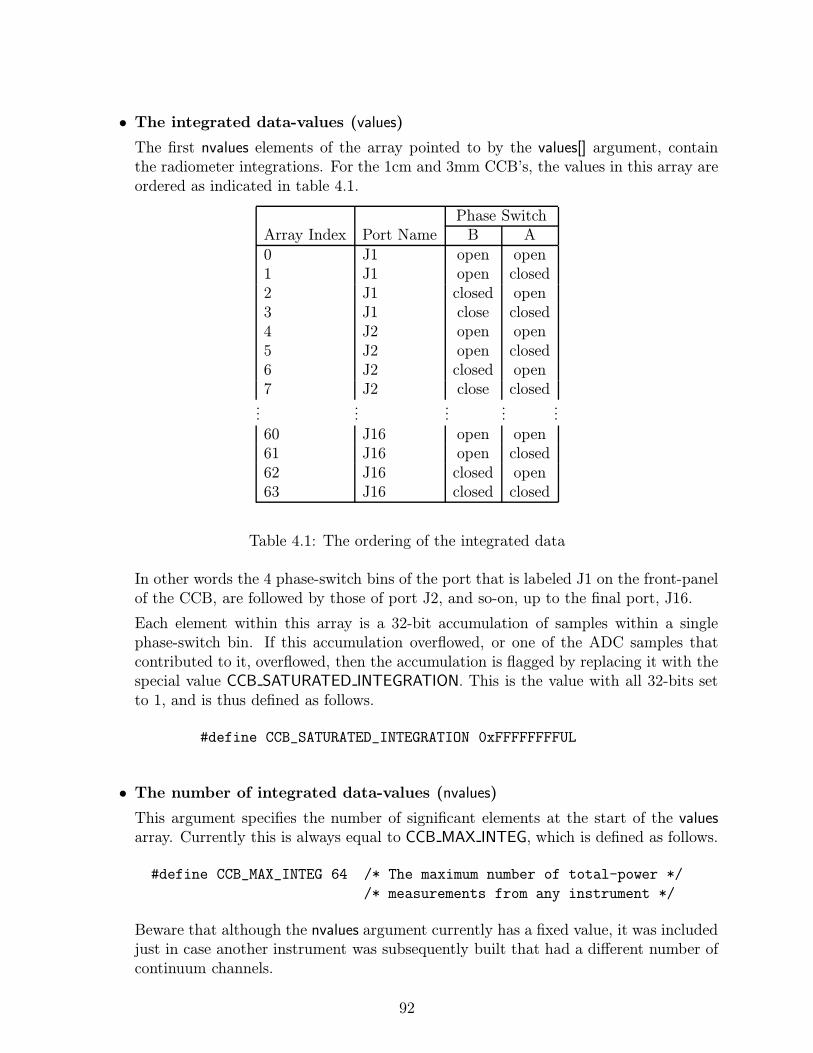
• The integrated data-values (values)
The first nvalues elements of the array pointed to by the values[] argument, containthe radiometer integrations. For the 1cm and 3mm CCB’s, the values in this array areordered as indicated in table 4.1.
Phase SwitchArray Index Port Name B A0 J1 open open1 J1 open closed2 J1 closed open3 J1 close closed4 J2 open open5 J2 open closed6 J2 closed open7 J2 close closed...
......
......
60 J16 open open61 J16 open closed62 J16 closed open63 J16 closed closed
Table 4.1: The ordering of the integrated data
In other words the 4 phase-switch bins of the port that is labeled J1 on the front-panelof the CCB, are followed by those of port J2, and so-on, up to the final port, J16.
Each element within this array is a 32-bit accumulation of samples within a singlephase-switch bin. If this accumulation overflowed, or one of the ADC samples thatcontributed to it, overflowed, then the accumulation is flagged by replacing it with thespecial value CCB SATURATED INTEGRATION. This is the value with all 32-bits setto 1, and is thus defined as follows.
#define CCB_SATURATED_INTEGRATION 0xFFFFFFFFUL
• The number of integrated data-values (nvalues)
This argument specifies the number of significant elements at the start of the valuesarray. Currently this is always equal to CCB MAX INTEG, which is defined as follows.
#define CCB_MAX_INTEG 64 /* The maximum number of total-power */
/* measurements from any instrument */
Beware that although the nvalues argument currently has a fixed value, it was includedjust in case another instrument was subsequently built that had a different number ofcontinuum channels.
92
ccb log msg callback() – Routing telemetry log-message messages
When the server sends error and informational messages to the manager, to be logged, theyare sent as log-message messages over the telemetry link.
The public ccb log msg callback() function is used to register the callback function that willsubsequently be called by ccb client communicate() whenever it receives a log-message mes-sage. Since the same callback function is invoked whenever the client end of the communica-tions library needs to report an internal error, it is recommended that ccb log msg callback()be the first CCB library function called after new CCBClientLink() returns. Otherwise someerror messages may end up being reported to the manager program’s stderr, which may notbe visible to the observer.
The CCB LOG MSG FN macro should be used for the declarations and prototypes of suitablecallback functions, and the CCBLogMsgFn typedef can be used for recording pointers to them.
#define CCB_LOG_MSG_FN(fn) int (fn)(CCBClientLink *cl, \
void *data, \
const CCBTimeStamp *ts, \
const char *msg, \
unsigned long id, \
CCBLogLevel level)
typedef CCB_LOG_MSG_FN(CCBLogMsgFn);
int ccb_log_msg_callback(CCBClientLink *cl, CCBLogMsgFn *fn, void *data);
The callback function is registered via the fn argument of ccb log msg callback(), and anyapplication-specific resources that should be passed to the callback are specified via the dataargument. The log message itself is passed as a normal ’\0’ terminated C string, via themsg argument, and the corresponding unique numeric identifier of the message is passed inthe id argument. The level argument reports the significance of the message, as enumeratedby the CCBLogLevel type.
typedef enum {
CCB_INFO, /* A purely informational message */
CCB_NOTICE, /* A note about a probably inconsequential event */
CCB_WARNING, /* A warning about a potentially problematic event */
CCB_ERROR, /* A report of an event requiring operator attention */
CCB_FAULT, /* A report of a condition that is corrupting data */
CCB_FATAL /* A report of a system-wide failure */
} CCBLogLevel;
93

Note that these enumerators simply provide symbolic names for the level values defined byYGOR.
4.14 A TCL wrapper around the CCB client API
Ostensibly for the purpose of facilitating a GUI demonstration CCB client using Tcl/Tk, butalso useful for quick test programs, a dynamically loadable Tcl wrapper interface is providedfor the CCB client communications library. This can either be linked with directly by anyprogram that embeds Tcl, or can be loaded into a running copy of the standard wish or tclshshell programs that come with the Tcl/Tk distribution. To load the library into an alreadyexecuting copy of wish, one types:
load ./libccbtclclient.so
Note that if the above library isn’t in the current directory, the ./ component in the aboveshould be replaced by the path of the directory where it is located. Alternatively, if thelibrary is installed in one of the directories that are searched automatically by the run-timelinker, then there is no need to specify a directory at all. The Tcl wrapper defines a singleTcl command called ccb. The first argument of this command is a sub-command, and mustbe one of the following.
• ccb connect host
This command initiates a non-blocking connection to the specified host. The hostargument can either be a numeric IP address or a textual IP address. Before returning,this command registers the sockets that it opens with the Tcl event loop.
• ccb disconnect
This terminates any existing connection to a CCB server, and withdraws the defunctsockets from the Tcl event loop.
• ccb send ...
This command is the command responsible for queuing all commands destined for theremote CCB server. Its first argument identifies the type of control-command to besent, and is followed by any arguments that the command requires. The followingcommands are defined.
– ccb send start scan mjd seconds
This starts a new scan on the day specified by the Modified Julian Day numbermjd, at the time of day specified by the seconds argument.
94

– ccb send stop scan
This starts an intra-scan ASAP.
– ccb send dump scan adc samples frames
Start a dump-mode intra-scan ASAP. The adc argument should be a numberbetween 0 and 15, specifying the ADC whose samples are to be collected. Thesamples argument should be a positive integer specifying the maximum numberof samples that should be collected per integration, or the word max to specifythat the maximum number possible be collected. The frames argument shouldbe a positive integer specifying how many per-integration data-frames should bedelivered to the remote dump-mode clients, or the word all to specify that framesshould be delivered indefinitely.
– ccb send load driver type
Load either the real CCB device driver, or a driver that emulates the real devicedevice driver and its hardware. The type argument can take any of the followingvalues.
normal virtual
These names have the same meanings as the similarly named members of theCCBDriverType datatype.
– ccb send reset
This resets the CCB.
– ccb send ping
If any previously sent ping has not been responded to, this function throws anerror (use the Tcl catch command to see this). Otherwise it sends a ping commandto the CCB server.
– ccb send status request
This asks the CCB server to send us a message reporting the status of the CCBbackend. How the subsequent response is caught and responded to is documentedbelow.
– ccb send shutdown
This tells the remote CCB server to place the CCB electronics in a safe state,then shutdown the backend computer.
– ccb send reboot
This tells the remote CCB server to place the CCB electronics in a safe state,then reboot the backend computer.
– ccb send monitor period
This command configures the frequency of monitoring updates. The period argu-ment must be an integer specifying the monitoring period as a number of inte-gration periods.
95

– ccb send telemetry streams
This command tells the CCB server which telemetry streams it should send to us.Specifically, the streams argument specifies the set of telemetry streams that theCCB server should continue to send, expressed as a space separated list of zeroor more of the following names.
integ_stream monitor_stream log_stream
no_streams all_streams
These correspond to the similarly named CCBTelemetryStream enumerators (seepage 81).
– ccb send logger period
This command tells the CCB server how often to discard the history of sent logmessages, thus specifying the maximum rate at which repeated log messages willbe sent to us.
– ccb send set dacs counts0 counts1 counts2 counts3
This command tells the CCB server to set the miscellaneous analog outputs ofthe GPIO card to specified values, where the values are interpreted as the integercount inputs of the corresponding digital-to-analog converters. There are 4 analogoutputs, so up to 4 arguments are required. Each argument should either be aninteger DAC count between 0 and 4095, or the word last, to request that thespecified DAC input not be changed. More details about the analog outputs canbe found in section 4.11.1.
• ccb configure ...
This command configures specified parameters of the next scan or intra-scan. Its firstargument identifies the group of configuration parameters to be modified, and thisis followed by the corresponding configuration values. The following configurationcommands are defined.
– ccb configure phase switches active switches closed switchessamp per state
This configures the phase-switches in the receiver front-end. The arguments havethe same meanings as the synonymous arguments of the ccb set phase switch cnf()function. The first 2 arguments, which both refer to sets of phase-switches, areexpressed as space-separated lists of zero or more of the following names.
switch_a switch_b no_switches all_switches
These have the same meanings as the similarly named CCBPhaseSwitches enu-merators.
The final, samp per state argument is expressed as an integer.
96

– ccb configure cal diode ncal diode states diode times
This configures the calibration-diodes in the receiver front-end. The argumentshave the same meanings as the synonymous arguments of the ccb set cal diode-cnf() function.
The diode states argument is represented as a Tcl list of calibration-diode sets,each of which is expressed as a Tcl list of zero or more of the following names.
diode_a diode_b no_diodes all_diodes
These have the same meanings as the similarly named CCBCalDiodes enumerators.
The diode times argument is represented as a Tcl list of integers.
Note that the number of elements in the diode states and diode times argumentsmust both be at least equal to the value of the integer ncal argument.
– ccb configure timing phase switch dt diode rise dt diode fall dtinteg period roundtrip dt holdoff dt adc delay dt
This configures the parameters which affect the timing of integrations. The ar-guments are all integers and have the same interpretations as the synonymousarguments of the ccb set timing cnf() function.
– ccb configure sampler sample type
This configures the parameters which affect the digitized samples that are inputto the integrators and collected verbatim during dump-mode. The sample typeargument determines where the hardware gets the samples that it collects andintegrates. It should be one of the following names.
adc_samples fake_samples
which have the same meanings as their similarly named CCBSampleType enumer-ator counterparts.
• ccb attach ...
This command specifies a Tcl command that should be invoked when a given eventoccurs, such as the reception of a particular type of message from the CCB server.When the event next occurs, the specified Tcl command is invoked verbatim, withoutany arguments being appended. Where information is associated with the event, thespecified Tcl command can use the ccb get ... commands, documented shortly, to getthat information.
The type of event to attach the Tcl command to is specified via the fist argument ofthe ccb attach command, and the Tcl command that is to subsequently be invoked bythe event, is specified as the second argument. The possible events are as follows.
– ccb attach status command
Whenever a reply to a ccb send status request command is received the specifiedTcl command is executed. This Tcl command can use the ccb get status commandto retrieve the corresponding status information.
97

– ccb attach monitor command
Whenever a new packet of monitoring data is received, the specified Tcl commandis invoked. This Tcl command can use the ccb get monitor command to retrievethe received monitoring data.
– ccb attach integ command
Whenever data are received from a newly completed integration, the specified Tclcommand is invoked. This Tcl command can use the ccb get integ command toretrieve the integrated data.
– ccb attach log command
Whenever a log message is received from the CCB server or the CCB client library,the specified Tcl command is invoked. This Tcl command can use the ccb get logcommand to retrieve the log message.
– ccb attach error command
If a command that was sent to the CCB fails for any reason, the the specified Tclcommand is invoked. This Tcl command can use the ccb get error command toretrieve the problematic completion status of the original command.
• ccb get ...
This command provides a means of querying information from the Tcl wrapper. No-tably it allows one to get the contents of the last of each of a number of types ofmessage received from the CCB server.
The single argument of the ccb get command specifies what type of information is tobe retrieved. The retrieved data is passed back as the result string of the command.For those not familiar with Tcl, the result string is written to stdout if the commandis typed in at the command-line of wish or tclsh, or it can be interpolated into anargument of another Tcl command by invoking it between square brackets.
The available information requests are as follows.
– ccb get status
This retrieves the most recent CCB status that has been received in response to apreceding ccb send status request command. The result string is a space separatedlist of zero or more of the following status indicators.
link_down buffer_full hard_fault soft_fault
These correspond to the similarly named CCBGeneralStatus enumerators (seepage 87).
– ccb get monitor
This returns the most recently received batch of periodically sampled monitoringdata. The result string contains a space-separated list of the following items:
98

1. mjd - The date at which the message was generated, expressed as a ModifiedJulian day number
2. sec - The time at which the message was generated, expressed as the numberof complete seconds that had elapsed since the start of the above day.
3. ns - The fractional-seconds part of the time, expressed as an integer numberof nanoseconds.
4. scan - The scan-identification number that was sent with the start-scan orstop-scan command that initiated the originating scan.
5. number - The sequential number of the integration within the originatingscan.
6. fan12v - The actual voltage of the 12V fan PSU.
7. a8v - The actual voltage of the analog 8V PSU.
8. d5v - The actual voltage of the digital 5V PSU.
9. cnf done - A boolean value specifying whether all of the FPGAs have hadfirmware downloaded into them. It has one of the values true or false.
10. high temp - A boolean value specifying whether the temperature inside theCCB is too high. It has one of the values true or false.
11. ccb id - The ID of the cable-harness that is plugged into the front-panel ofthe CCB. See table 3.3, for details.
12. master info - A brace-enclosed array of monitoring information that pertainsto the master FPGA board (see below).
13. slave1 info - A brace-enclosed array of monitoring information that pertainsto the first slave FPGA board (see below).
14. slave2 info - A brace-enclosed array of monitoring information that pertainsto the second slave FPGA board (see below).
15. slave3 info - A brace-enclosed array of monitoring information that pertainsto the third slave FPGA board (see below).
16. slave4 info - A brace-enclosed array of monitoring information that pertainsto the fourth slave FPGA board (see below).
The master info, slave1 info, slave2 info, slave3 info and slave4 info fields, are eachbrace-enclosed lists of the following items:
1. d1 2v - The actual voltage of the digital 1.2V PSU.
2. d2 5v - The actual voltage of the digital 2.5V PSU.
3. d3 3v - The actual voltage of the digital 3.3V PSU.
4. d3 3v - The actual voltage of the analog 5V PSU.
5. hb - The mean voltage of the heartbeat signal.
6. cnf done - A boolean value specifying whether firmware has been loaded intothe FPGA. It has one of the values true or false.
7. cnf error - A boolean value specifying whether the firmware that was down-loaded into the FPGA is corrupt. It has one of the values, true or false.
99

– ccb get integ
This returns the integrated data from the most recently completed integrationperiod. The result string contains a space-separated list of the following integers:
1. mjd - The date at which the message was generated, expressed as a ModifiedJulian day number
2. sec - The time at which the message was generated, expressed as the numberof complete seconds that had elapsed since the start of the above day.
3. ns - The fractional-seconds part of the time, expressed as an integer numberof nanoseconds.
4. scan - The scan-identification number that was sent with the start-scan orstop-scan command that initiated the originating scan.
5. number - The sequential number of the integration within the originatingscan.
6. flags - This is a Tcl list of zero or more of the following integration status-flags:
cal_a_on, cal_b_on, integ_ok, slave0_ok,
slave1_ok, slave2_ok, slave3_ok
These flag-names have the same meanings as their similarly named CCBIn-tegFlags enumerator counterparts.
7. nvalues - The number of integrated values.
8. values... - The nvalues integrated values.
– ccb get log
This returns the most recently received log message. The result string is a spaceseparated list of the following items.
1. mjd - The date at which the message was generated, expressed as a ModifiedJulian day number
2. sec - The time at which the message was generated, expressed as the numberof complete seconds that had elapsed since the start of the above day.
3. ns - The fractional-seconds part of the time, expressed as an integer numberof nanoseconds.
4. id - The identifier of the error-reporting statement that generated the message.
5. level - One of the following words, indicating the significance of the message.
info notice warning error fault fatal
These correspond to the similarly named CCBLogLevel enumerators (see page 93).
6. text - The log-message itself, rendered as a properly formed Tcl list element.
– ccb get error
This retrieves the error completion status of the last control command that suf-fered an error. The result string contains one of the following values.
accepted garbled ignored syserr
100

These correspond to the similarly named CCBCmdStatus enumerators (see page 74).Note that since the CCB library only tells us the completion statuses of commandsthat fail, when this command returns the word accepted, this means that no com-mand has failed yet.
– ccb get time
Return the current date and time as two integers, the first being the date as aModified Julian Day number, and the second being the time of day, expressed asthe number of seconds elapsed since the start of the day.
The following is a short example Tcl script, giving an overview of how to use the interface.To try this script, cut and paste it into a file called tcl demo, then type:
tclsh tcl_demo
# Load the CCB Tcl interface.
load libccbtclclient.so
# Arrange for messages that are received from the CCB server to to be
# displayed to stdout. Note that the Tcl puts command is like C’s
# puts() function, and that in Tcl, sub-strings consisting of square
# brackets surrounding Tcl commands are replaced by the output that
# is generated by executing those commands.
ccb attach integ {puts "Integration: [ccb get integ]"}
ccb attach monitor {puts "Monitor: [ccb get monitor]"}
ccb attach log {puts "Log: [ccb get log]"}
ccb attach error {puts "Error: [ccb get error]"}
ccb attach status {puts "Status: [ccb get status]"}
# Turn on both phase switches, and configure 250 samples per
# phase-switch state (ie. 25us).
ccb configure phase_switches all_switches all_switches 250
# Change the default timing, to slow down integration periods from
# the default of 1ms to 1s (ie. 40000 * 25us = 1s).
ccb configure timing 10 1000 1000 40000 10 7 0
# Queue a stop-scan command to be sent, along with the above changed
# configuration, once a connection is established to the CCB server.
101
ccb send stop_scan
# Connect to the CCB server on the local machine.
ccb connect localhost
# Load the hardware-simulating device driver.
ccb send load_driver virtual
# The CCB starts out with all telemetry disabled, so send the
# to enable all telemetry.
ccb send telemetry all_streams
# Start the Tcl event loop.
set ::guard 0
vwait ::guard
Before running this, make sure that libccbtclclient.so is in the normal run-time shared-librarypath, or add that directory to your LD LIBRARY PATH variable. Also, of course, first runthe ccbserver program, so that the script has something to talk to, after making sure thatthe IP address of the host that you run the script on is in the ccb authorized ips file.
102

Chapter 5
The CCB server communications API
The CCB server-communications library performs most of the work needed to implement theCCB server. It basically acts as a gateway between the manager and both the CCB devicedriver and the operating system. Writing a complete server involves providing callbackfunctions that load and unload the device driver, send commands to the device driver, andreboot and shutdown the real-time CPU, along with a select() based event loop, controlledby the library.
5.1 Include files
The datatype-declarations, function-prototypes and constants of the public API of the CCB-server communications-library are contained in the following include files.
• ccbserverlink.h
This header-file contains all of the public function-prototypes and datatype declarationsthat are specific to to the server side of the communications link.
• ccbcommon.h
This header-file contains the public function-prototypes and datatype declarations thatare shared between both the client and the server communications libraries. Since thisfunction is included by ccbserverlink.h, it isn’t usually necessary for the application toexplicitly include it.
• ccbconstants.h
This header-file contains all of the constants that affect the operation of the communi-cations link. Since this function is included by ccbcommon.h, it isn’t usually necessaryfor the application to explicitly include it.
103
5.2 The CCB-server communications library
The library that implements the CCB-server communications API, is a shared library calledlibccbserverlink.so. Under Solaris and Linux, this filename is actually a symbolic link to themost recent version of the library.
Among other advantages, the use of a shared library rather than a static library has thebenefit, at least under Solaris and Linux, of allowing one to restrict which symbols areexported into the namespace of the application. This not only prevents programs from usingunstable private interfaces, but also greatly reduces namespace pollution and the possibilityof symbol-name clashes.
Linking a C program with this library under either Linux or Solaris can be done as follows.
gcc -o foo *.o -lccbserverlink
Note that linkage instructions built into the shared library cause other unspecified libraries,such as -lsocket under Solaris, to be linked automatically.
5.3 Creating the resources used to communicate with
CCB managers
The CCB server creates the resources that are needed for communications with the managerby calling new CCBServerLink().
CCBServerLink *new_CCBServerLink(CCBServerDriver *normal,
CCBServerDriver *virtual);
In addition to allocating resources, this binds the server to the CCB control and teleme-try TCP/IP ports, whose numbers are parameterized, as mentioned earlier, by the CCB-CONTROL PORT and CCB TELEMETRY PORT macros in ccbconstants.h. It doesn’t waitfor a manager to connect, but it does make the control and telemetry ports receptive toincoming connections, specifying a queue length of 1. Both ports are configured to be non-blocking, such that if a connection request is dropped between select() reporting activity, andaccept() being called, the process doesn’t block forever in accept(). The returned CCBServer-Link object pointer is opaque, meaning that the definition of the structure that it points tois not exported to applications in the public header-file.
The arguments of this function are interpreted as follows.
104
• The normal CCB device driver (normal)
The interface object of the real CCB device driver is passed in this argument. It musthave been allocated by calling new CCBServerDriver(). To facilitate development, thisargument can be NULL, provided that the virtual argument isn’t also NULL.
• The simulated CCB device driver (virtual)
The interface object of a CCB device-driver emulator is passed in this argument. Itmust have been allocated by calling new CCBServerDriver(). The emulator should sim-ulate both the CCB device driver, and the CCB hardware. It is used for off-line testingof both the server and client software.
5.3.1 The CCB server’s device-driver interface
The CCB server talks to a given CCB device driver via a set of method functions encapsulatedin a corresponding CCBServerDriver object. Objects of this type are allocated by calling new-CCBServerDriver().
CCBServerDriver *new_CCBServerDriver(void *data,
CCBDriverLoadFn *load_driver,
CCBDriverUnloadFn *unload_driver,
CCBDriverTellFn *tell_driver,
CCBDriverSelectEventsFn *select_events,
CCBDriverCheckEventsFn *check_events,
CCBRebootRTCFn *reboot_rtc,
CCBShutdownRTCFn *shutdown_rtc,
CCBSetDacsFn *set_dacs);
The arguments of new CCBServerDriver() are interpreted as follows.
• Application specific callback data (data)
This argument is a pointer to any resources that the calling application needs to havepassed to its callback functions.
• The callback which loads the device driver (load driver)
This argument specifies the function that the CCBServerLink object should call whenit needs to load the CCB device driver. It is guaranteed that before the first call tothis function, and thereafter between calls to this function, the driver will have beenunloaded by calling the unload driver callback function.
Suitable functions to pass in the load driver argument should be declared and proto-typed using the CCB DRIVER LOAD FN() macro. Pointers to them can be recorded invariables of type CCBDriverLoadFn.
105

#define CCB_DRIVER_LOAD_FN(fn) int (fn)(CCBServerLink *sl, \
void *data)
typedef CCB_DRIVER_LOAD_FN(CCBDriverLoadFn);
When this function is called, it is passed the value of the data argument of new-CCBServerLink(). If successful, load driver callbacks should return 0. Otherwise theyshould return 1, and set errno accordingly.
• The callback which unloads the device driver (unload driver)
This argument specifies the function that the CCBServerLink object should call whenit needs to unload the CCB device driver. Beware that this function may be calledwhen no driver is currently loaded, and that this shouldn’t be interpreted as an error.
Suitable functions to pass in the unload driver argument should be declared and proto-typed using the CCB DRIVER UNLOAD FN() macro. Pointers to them can be recordedin variables of type CCBDriverUnloadFn.
#define CCB_DRIVER_UNLOAD_FN(fn) int (fn)(CCBServerLink *sl, \
void *data)
typedef CCB_DRIVER_UNLOAD_FN(CCBDriverUnloadFn);
When this function is called, it is passed the value of the data argument of new-CCBServerLink(). If successful, unload driver callbacks should return 0. Otherwisethey should return 1, and set errno accordingly.
• The callback that controls the device driver (tell driver)
This argument specifies the function that the CCBServerLink object should call whenit needs to send a command to the CCB device driver. This function isn’t called whenthe device driver isn’t loaded.
Suitable functions to pass in the tell driver argument should be declared and proto-typed using the CCB DRIVER TELL FN() macro. Pointers to them can be recorded invariables of type CCBDriverTellFn.
#define CCB_DRIVER_TELL_FN(fn) int (fn)(CCBServerLink *sl, \
void *data, const CCBDriverCmd *cmd)
typedef CCB_DRIVER_TELL_FN(CCBDriverTellFn);
When this function is called, it is passed the value of the data argument of new-CCBServerLink(), plus a command argument, as described below. If successful, tell-driver callbacks should return 0. Otherwise they should return 1, and set errno accord-ingly.
The CCBDriverCmdID enumeration lists the types of commands that can be sent to theCCB device driver.
106

typedef enum {
CCB_DRV_CONF_SCAN, /* Install a new scan */
/* configuration. */
CCB_DRV_STAGE_SCAN, /* Start a new scan at a */
/* specified time */
CCB_DRV_INTRA_SCAN, /* Start an intra-scan ASAP */
CCB_DRV_DUMP_SCAN /* Start a dump-mode intra-scan ASAP */
} CCBDriverCmdID;
The CCBDriverCmd datatype contains a union of all driver commands, prefixed with aCCBDriverCmdID member identifying which member of the union is to be used.
struct CCBDriverCmd {
CCBDriverCmdID type; /* The type of command */
union {
CCBDrvConfScan conf; /* type==CCB_DRV_CONF_SCAN */
CCBDrvStageScan stage; /* type==CCB_DRV_STAGE_SCAN */
CCBDrvIntraScan intra; /* type==CCB_DRV_INTRA_SCAN */
CCBDrvDumpScan dump; /* type==CCB_DRV_DUMP_SCAN */
} pars;
};
The individual commands communicated by this structure are defined as follows.
– Configure the next scan
Before starting a new scan with the stage-scan, intra-scan or dump-scan commands,CCBServerLink objects invoke this driver command to configure the hardware forthe new scan. The parameters of the scan are encapsulated in the conf memberof the pars union in a structure of the following type.
typedef struct {
CCBPhaseSwitchCnf phase; /* The phase-switch */
/* configuration. */
CCBCalDiodeCnf cal; /* The calibration diode */
/* configuration. */
CCBTimingCnf timing; /* The hardware timing */
/* configuration. */
CCBSamplerCnf sampler; /* The sampler */
/* configuration */
} CCBDrvConfScan;
The members of this structure are encapsulated configuration groupings of thetypes that are returned by the ccb get * cnf() configuration lookup functions.
107
– Stage a new observing scan
When the server library receives a start-scan command, it uses the configure-scandriver-command to pass the configuration parameters of the requested scan tothe firmware, then invokes the stage-scan driver-command to initiate the scan ata specified time. The parameters of this command are encapsulated within astructure of the following type.
typedef struct {
unsigned long scan; /* The numeric scan identifier */
time_t start_time; /* The date and time of the second */
/* at which to start the scan, */
/* expressed as a UNIX time. */
} CCBDrvStageScan;
The scan member forwards the numeric scan identifier that the manager sentin the start-scan command, so that the driver can use it to tag integration andmonitoring data from the new scan. After receiving this command, the devicedriver waits until the rising edge of the 1-PPS signal that matches the specifiedstart time and date, before starting the new scan.
– Start an intra-scan
When the server library receives a stop-scan command from the manager, it usesthe configure-scan driver-command to pass the configuration parameters of therequested scan to the firmware, then invokes the intra-scan driver-command toimmediately initiate an intra-scan. The parameters of this command are encap-sulated within a structure of the following type.
typedef struct {
unsigned long scan; /* The numeric scan identifier */
} CCBDrvIntraScan;
The scan member forwards the numeric scan identifier that the manager sentin the stop-scan command, so that the driver can use it to tag integration andmonitoring data from the new intra-scan.
– Start a dump-mode intra-scan
When the server library receives a dump-scan command from the manager, ituses the configure-scan driver-command to pass the configuration parameters ofthe requested scan to the firmware, then finally invokes the dump-scan driver-command to immediately initiate a dump-mode intra-scan. The parameters ofthis command are encapsulated within a structure of the following type.
typedef struct {
unsigned long scan; /* The numeric scan identifier */
unsigned short adc; /* The ADC to dump */
unsigned long samples; /* The max number of samples to */
/* collect per integration. */
} CCBDrvDumpScan;
108
The adc member should be an integer between 0 and CCB NUM ADC−1, speci-fying the ADC whose samples are to be collected. The samples member, shouldeither be CCB DUMP MAX SAMPLES, to specify that the maximum number ofsamples/integration be collected, or a positive integer specifying the desired num-ber.
• The callback that indicates events to watch (select events)
This argument specifies a function which is called each time just before the CCBserver’s event loop invokes select() to wait for I/O. The driver is expected to add anyfile-descriptors that it wants to have watched for activity, and/or register an inactivity-timeout.
Suitable functions to pass in the select events argument should be declared and proto-typed using the CCB DRIVER SELECT EVENTS FN() macro. Pointers to them can berecorded in variables of type CCBDriverSelectEventsFn.
#define CCB_DRIVER_SELECT_EVENTS_FN(fn) int (fn)( \
CCBServerLink *sl, void *data, \
fd_set *rfds, fd_set *wfds, int *maxfd, \
struct timeval *timeout)
typedef CCB_DRIVER_SELECT_EVENTS_FN(CCBDriverSelectEventsFn);
When this function is called, it is passed the value of the data argument of new-CCBServerLink(). The callback should use the standard FD SET() macro to installfile-descriptors of interest in *rfds and *wfds, where the former is for descriptors to bewatched for readability, and the latter is for those to be watched for writability. If thevalue of *maxfd is less than the maximum value of any descriptor that the callback hasadded to rfds or wfds, then it should be set to the latter maximum. If the driver wantsto be called on inactivity-timeouts, then it should register the timeout that it wants inthe timeout argument.
Normally the callback should return 0 to indicate success. If an unrecoverable erroroccurs, it should return 1, and set errno accordingly.
• The callback that checks for driver events (check events)
This argument specifies a function which is called each time when the CCB server’scall to select() returns. The driver is expected to handle any indicated file-descriptoractivity, or inactivity-timeout.
Suitable functions to pass in the check events argument should be declared and proto-typed using the CCB DRIVER CHECK EVENTS FN() macro. Pointers to them can berecorded in variables of type CCBDriverCheckEventsFn.
#define CCB_DRIVER_CHECK_EVENTS_FN(fn) int (fn)( \
CCBServerLink *sl, void *data, \
fd_set *rfds, fd_set *wfds)
typedef CCB_DRIVER_CHECK_EVENTS_FN(CCBDriverCheckEventsFn);
109

When this function is called, it is passed the value of the data argument of new-CCBServerLink(). If the select() inactivity timeout was triggered, the rfds and wfdsarguments are both NULL. Otherwise they contain the sets of file-descriptors that arenow ready for reading and writing, respectively.
Normally the callback should return 0 to indicate success. If an unrecoverable erroroccurs, it should return 1, and set errno accordingly.
• The callback that reboots the computer (reboot rtc)
This argument specifies the function that the CCBServerLink object should call toreboot the CCB computer.
Suitable functions to pass in the reboot rtc argument should be declared and proto-typed using the CCB REBOOT RTC FN() macro. Pointers to them can be recorded invariables of type CCBRebootRTCFn.
#define CCB_REBOOT_RTC_FN(fn) int (fn)(CCBServerLink *sl, \
void *data)
typedef CCB_REBOOT_RTC_FN(CCBRebootRTCFn);
When this function is called, it is passed the value of the data argument of new-CCBServerLink(). When a reboot is successfully initiated, reboot rtc callbacks shouldreturn 0. Otherwise they should return 1, and set errno accordingly.
• The callback that shuts-down the computer (shutdown rtc)
This argument specifies the function that the CCBServerLink object should call toshutdown both the CCB computer and the CCB hardware.
Suitable functions to pass in the shutdown rtc argument should be declared and proto-typed using the CCB SHUTDOWN RTC FN() macro. Pointers to them can be recordedin variables of type CCBShutdownRTCFn.
#define CCB_SHUTDOWN_RTC_FN(fn) int (fn)(CCBServerLink *sl, \
void *data)
typedef CCB_SHUTDOWN_RTC_FN(CCBShutdownRTCFn);
When this function is called, it is passed the value of the data argument of new-CCBServerLink(). When a shutdown is successfully initiated, shutdown rtc callbacksshould return 0. Otherwise they should return 1, and set errno accordingly.
• The callback that sets the misc analog outputs (set dacs)
This argument specifies the function that the CCBServerLink object should call to sendnew values to the digital-to-analog converters of the GPIO-card’s miscellaneous analogoutputs.
110

Suitable functions to pass in the set dacs argument should be declared and prototypedusing the CCB SET DACS FN() macro. Pointers to them can be recorded in variablesof type CCBSetDacsFn.
#define CCB_SET_DACS_FN(fn) int (fn)(CCBServerLink *sl, void *data, \
unsigned short counts[CCB_GPIO_NDAC])
typedef CCB_SET_DACS_FN(CCBSetDacsFn);
When this function is called, it is passed the value of the data argument of new-CCBServerLink(). Its counts[] argument is interpreted as documented in section 4.11.1,for the ccb queue set dacs cmd() function.
Callbacks of this type should return 0 if successful. Otherwise they should return 1,and set errno accordingly.
The return value of new CCBServerDriver() is a pointer to an opaque CCBServerDriver objectthat can be passed to new CCBServerLink(), or NULL if an error occurred.
Once a CCBServerDriver object has been passed to new CCBServerLink(), it shouldn’t bedeleted until after del CCBServerLink() is called to delete the corresponding server object.Objects returned by new CCBServerDriver() are deleted by calling del CCBServerDriver().
CCBServerDriver *del_CCBServerDriver(CCBServerDriver *drv);
The argument of this function is the object to be deleted (which can be NULL. The returnvalue of the function is always NULL, so that one can type:
drv = del_CCBServerDriver(drv);
This both deletes the object pointed to by drv, and then sets this pointer to NULL, toensure that subsequent illegal attempts to access the object through this pointer produce asegmentation-fault, rather than appearing to work, while actually doing something bad.
5.4 Shutting down server communications
When the CCB server shuts down, it releases the resources that were allocated by new-CCBServerLink() and closes all of its sockets, by calling del CCBServerLink().
CCBServerLink *del_CCBServerLink(CCBServerLink *sl);
111

This function always returns NULL to allow the caller to type:
CCBServerLink *sl;
...
sl = del_CCBServerLink(sl);
This sets the invalidated sl pointer variable to NULL, such that if any statement subsequentlytries to access the deleted object through this pointer, it is rewarded with a segmentationfault, rather than producing unpredictable behavior.
5.5 Server I/O multiplexing
To enable the CCB server to handle the telemetry and control links at the same time asinteracting with the CCB device driver, the server library uses non-blocking socket I/O whenreading and writing messages. The driver is expected to do the same. The select()-basedevent-loop is invoked by the server by calling the ccb server event loop() function.
int ccb_server_event_loop(CCBServerLink *ccb);
The rfds and wfds arguments are the file descriptor sets that select() returned. Normally ccb-server select args() returns 0, but if an error occurs, it returns 1 and sets errno accordingly.
5.6 Queuing replies to control commands
All replies to control commands are queued internally by the library, so there are no publicAPI functions related to this.
5.7 Queuing outgoing telemetry messages
Messages to be sent to the manager over the telemetry link are placed in message-specificqueues within the corresponding CCBServerLink object, as described in section 4.13. The ccb-server event loop() dispatches such messages to the manager. Whenever it finishes sendinga message, it chooses a new message from the highest priority queue that contains at leastone message, encodes this and starts to send the result to the manager.
The functions that the CCB server uses to queue messages in the appropriate queues, aredocumented in the following subsections.
112

5.7.1 Queuing outgoing monitor-data messages
The CCB server uses the ccb queue monitor msg() function to queue monitor-data messagesfor later transmission.
int ccb_queue_monitor_msg(CCBServerLink *sl,
const CCBTimeStamp *t,
unsigned long scan,
unsigned long number,
const CCBRawMonitorData *rmd);
Apart from the initial sl argument, the arguments of this function are as described in sec-tion 4.13, except for the rmd argument, which is a pointer to a CCBRawMonitorData data-type(see section 3.6).
5.7.2 Queuing outgoing integ-data messages
The CCB server uses the ccb queue integ msg() function to queue integ-data messages forlater transmission.
int ccb_queue_integ_msg(CCBServerLink *sl,
const CCBIntegFrame *integ);
The integ argument must be a pointer to the variable that contains the header informationand integrated data of the originating integration period. This variable has the followingdata-type.
typedef struct {
CCBTimeStamp ts; /* The start-time of the */
/* integration-period. */
unsigned long scan; /* The unique ID of the parent scan */
unsigned long integ; /* The sequential ID of the */
/* integration period within the */
/* parent scan. */
unsigned short flags; /* A bitwise union of CCBIntegFlags */
/* enumerators. */
unsigned long values[CCB_MAX_INTEG]; /* The integrated data. */
} CCBIntegFrame;
The ordering and properties of integrated values within the values member of the CCBIn-tegFrame structure are discussed in section 4.13.
113

ccb zero integ frame()
CCBIntegFrame objects can be zero-initialized by calling the function, ccb zero integ frame(),which has the prototype:
void ccb_zero_integ_frame(CCBIntegFrame *f);
5.7.3 Queuing outgoing dump-frame messages
The CCB server uses the ccb queue dump msg() function to queue dump-frame messages forlater transmission to remote dump-mode client programs.
int ccb_queue_dump_frame_msg(CCBServerLink *sl,
const CCBDumpFrame *df);
The df argument must be a pointer to the variable that contains the header information anddump-mode samples of the originating integration period. This variable has the followingdata-type.
typedef struct {
CCBTimeStamp ts; /* The start-time of the integration period */
unsigned long scan; /* The unique ID of the parent scan */
unsigned long integ; /* The sequential ID of the integration */
/* period within the parent scan. */
unsigned short flags; /* A bitwise union of CCBIntegFlags */
/* enumerators. */
unsigned short pswlen; /* The number of samples per phase-switch */
/* state. */
unsigned char phase_a; /* One bit denoting each of the 4 repeated */
/* states of the switching pattern of */
/* phase-switch A, where the least */
/* significant bit denotes the state */
/* of the switch at the start of each */
/* phase-switch cycle. */
unsigned char phase_b; /* One bit denoting each of the 4 repeated */
/* states of the switching pattern of */
/* phase-switch B, where the least */
/* significant bit denotes the state */
/* of the switch at the start of each */
/* phase-switch cycle. */
114

unsigned short nsample; /* The number of samples in samples[] */
unsigned short samples[CCB_DUMP_MAX_SAMPLES]; /* The ADC samples */
} CCBDumpFrame;
The samples member should be an array of nsample samples, where nsample should be thesmaller of, the number of samples that the manager originally requested, or CCB DUMP-MAX SAMPLES (see section 4.11.1).
The i’th element of the samples array should contain the ADC sample that started to beacquired i × 100ns from the start of the integration period. This must be a 14-bit ADCsample, plus a 15th bit that should be 1 if the ADC reported an overflow, or zero otherwise.The remaining bits should be zero. The number of bits per ADC sample, is parameterizedby the CCB ADC SAMPLE SIZE macro, as follows:
#define CCB_ADC_SAMPLE_SIZE 14
A bit-mask that can be used to select these bits, is parameterized by the CCB ADC SAMPLE-MASK macro, as follows.
#define CCB_ADC_SAMPLE_MASK ((1<<CCB_ADC_SAMPLE_SIZE)-1)
Similarly, a bit-mask that can be used to select the overflow bit, is parameterized by theCCB ADC OVERFLOW MASK macro, as follows.
#define CCB_ADC_OVERFLOW_MASK (1<<14)
ccb zero dump frame()
CCBDumpFrame objects can be zero-initialized by calling the function, ccb zero dump frame(),which has the prototype:
void ccb_zero_dump_frame(CCBDumpFrame *f);
ccb phase switch sequence()
The appropriate values to assign to the phase a and phase b fields of a CCBDumpFramevariable, can be computed by calling the ccb phase switch sequence() function. This has thefollowing prototype:
115

int ccb_phase_switch_sequence(const CCBConfig *cnf,
unsigned char *phase_a,
unsigned char *phase_b);
The first argument must be the configuration of the originating scan of the dump-mode data,and pointers to the phase a and phase b fields of a CCBDumpFrame object, should be passeddirectly to this function, via the correspondingly named function-arguments.
5.7.4 Queuing outgoing log-message messages
The CCB server uses the ccb log server msg() function to queue formatted log messages forlater transmission.
int ccb_log_server_msg(CCBServerLink *sl, CCBLogLevel level,
unsigned long id, const char *fmt, ...);
The level argument indicates the significance of the message, as described in section 4.13.
The id argument should be specified as CCB LOGID(?). As documented in section 2.9, thistells scripts that the makefile runs before compilation, to replace the ? character with aunique log ID.
The fmt argument is a standard printf-style format string, and is followed by the argumentsthat its format-specifiers refer to. Note that if gcc’s -Wformat warning option is used whencompiling code that calls this function, both the contents of the format string and the typesof the corresponding arguments are checked by the compiler.
Where necessary, the formatted log message is silently truncated to fit within the CCB-MAX LOG byte maximum that is imposed by the CCBLogMsg message structure describedin section 6.2.3.
Normally ccb log server msg() returns 0, but if a serious error occurs, non-zero is returned,and errno is set accordingly. Truncation is not considered to constitute a serious error.
116

Chapter 6
Library internals
The client and server communications libraries are comprised of three logical layers. Goingfrom the highest level to the lowest level layer, the layers are as follows.
• The CCB interface layer. This is the only part of the library that is specific to theCCB. In addition to providing the public-interface functions described above, it definesall of the CCB message types and aggregates the resources of the control and telemetryconnections.
• The message translation layer. This layer interprets the message definitions specifiedby the CCB interface layer.
• The packet buffer layer. For output messages, this layer converts host-specific datatypesto corresponding portable byte streams, and aggregates the results within the internalpacket buffer of the output stream, starting with a byte count, ready for transmission.For input messages this layer, which is passed a completely read message within theinternal packet buffer of the input stream, decodes the contents of the message, andpasses the result to the message translation layer using native datatypes.
• The I/O layer. This layer handles non-blocking reading and writing of the raw bytestreams, of which each message is composed, using the initial 4-byte integer of eachmessage to determine how much to read and write.
This is illustrated in the communication stack shown in figure 6.1.
117
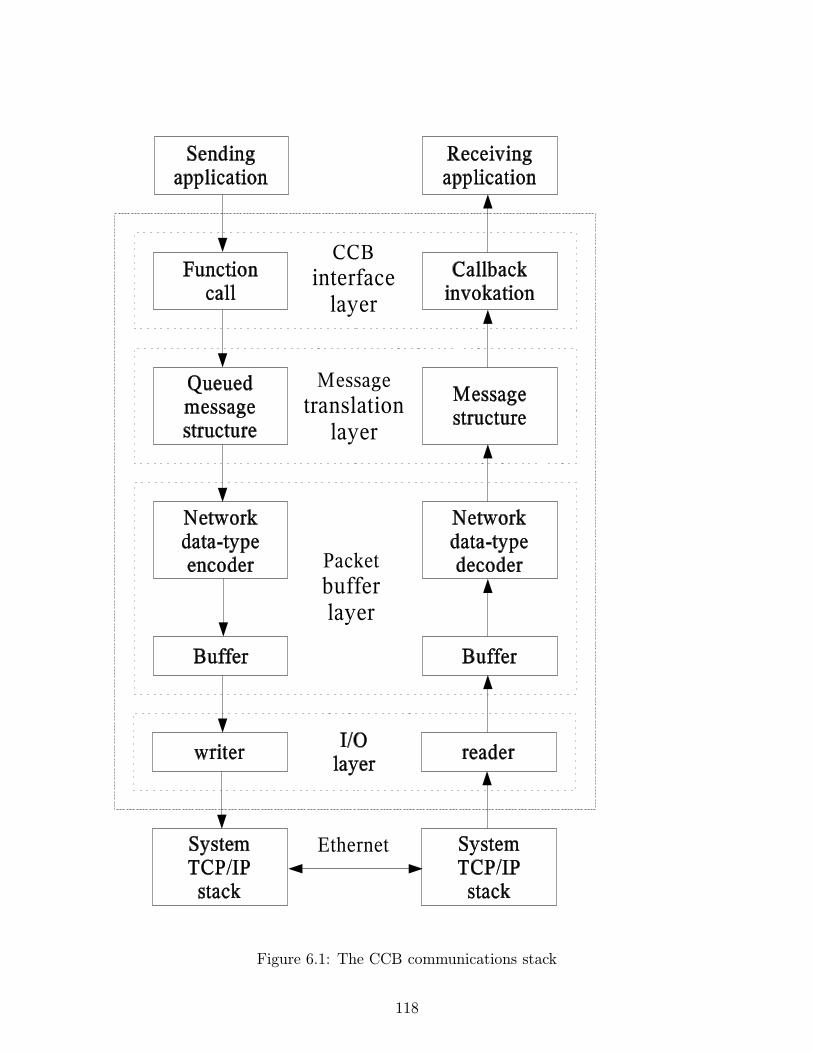
Figure 6.1: The CCB communications stack
118

6.1 The message translation layer
6.1.1 Message structure specification
In order to convert the contents of the previously described message structures to and fromportable network byte streams, the message-translation layer of the library needs to knowexactly what these structures contain, and how to access each of their members. This sectionexplains how this information is provided.
6.1.2 Supported data-types within message structures
Since the communications library can only encode and decode data-types that it knowsabout, all message structures are required to have members that are declared using thetypes described in the following table.
Enumerator Host data-type Network data-typeCCB NET ASCII char 8-bit unsigned charCCB NET BYTE signed char 8-bit signed integerCCB NET UBYTE unsigned char 8-bit unsigned integerCCB NET SHORT short 16-bit signed integerCCB NET USHORT unsigned short 16-bit unsigned integerCCB NET LONG long 32-bit signed integerCCB NET ULONG unsigned long 32-bit unsigned integerCCB NET FLOAT float 32-bit floating pointCCB NET DOUBLE double 64-bit floating point
Note that all integer types are transfered over the network in big-endian, 2’s-complementformat, and that the two floating point data-types are transfered in big-endian IEEE-754format.
Also note that the CCB NET ASCII enumerators tells the message translation layer that theassociated arrays of characters should be interpreted as ’\0’ terminated C strings. These areactually transfered over the network as variable length arrays of bytes, preceded by lengthcounts.
6.1.3 CCBNetMsg - The base-class of all messages
The communications library requires that the first member of all message structures be aCCBNetMsg member.
119

typedef struct {
long type; /* The type of the parent message-structure */
} CCBNetMsg;
This allows message structures to be passed to the message translation layer of the libraryusing pointers to their initial CCBNetMsg structure. As will be described shortly, the valueof the type member of this structure refers the library to a description of the actual messagestructure that has been passed.
6.1.4 Some example message structures
To see how the contents of message structures are described to the translation-layer ofthe communications library, consider the following two example message structures, calledCCBExampleMsg1, and CCBExampleMsg2:
#define SDIM 20; /* The size of the example string member */
/* in the following message structure. */
typedef struct { /* Example message structure 1 */
CCNNetMsg base; /* The message identification header */
char string[SDIM]; /* A string to be transmitted */
unsigned short slen; /* strlen(string) */
} CCBExampleMsg1;
typedef struct { /* Example message structure 2 */
CCNNetMsg base; /* The message identification header */
unsigned long foo; /* A <= 32-bit unsigned number */
} CCBExampleMsg2;
6.1.5 CCBNetMsgMember – Message field descriptions
With the exception of the obligatory initial CCBNetMsg member, each member of eachmessage structure is described to the library using a CCBNetMsgMember structure.
typedef struct {
const char *name; /* The textual name of the member */
size_t offset; /* The byte-offset of the member in the */
/* local message structure */
CCBNetDataType type; /* The enumerated data-type of the member */
int ntype; /* The number of elements in the member */
} CCBNetMsgMember;
120

The following example code shows how arrays of these CCBNetMsgMember structures areused to describe the elements of the two example message structures.
#include <stddef.h>
#include "ccbnetobj.h"
/* The description of the members of CCBExampleMsg1 */
static const CCBNetMsgMember ccb_example_msg1_members[] = {
{"string", offsetof(CCBExampleMsg1, string), CCB_NET_ASCII, SDIM},
{"slen", offsetof(CCBExampleMsg1, slen), CCB_NET_USHORT, 1},
};
/* The description of the members of CCBExampleMsg2 */
static const CCBNetMsgMember ccb_example_msg2_members[] = {
{"foo", offsetof(CCBExampleMsg2, foo), CCB_NET_ULONG, 1},
};
6.1.6 CCBNetMsgInfo – Individual message descriptions
In addition to descriptions of the contents of each message type, the communications libraryneeds to know both the host-dependent size of the message data-structures, and a convenientway for the various parts of the library to refer each other to a given type of message. Eachmessage is thus further described using a CCBNetMsgInfo structures.
typedef struct {
int type; /* The message-type enumerator */
const char *name; /* The name of this message-type */
const CCBNetMsgMember *member; /* Descriptions of each member */
int nmember; /* The number of elements in member[] */
size_t native_size; /* The host-dependent size of the */
/* the corresponding message structure */
} CCBNetMsgInfo;
The name field, which isn’t currently used by the library, may in future be used when printingout the contents of messages for debugging purposes.
For a given network connection, the communications library needs separate descriptionsof the messages that it is expected to transmit, and those that it is expected to receive.To do this the CCB interface layer registers two arrays of CCBNetMsgInfo structures per
121

connection, one describing outgoing messages, while the other describes incoming messages.The indexes of elements in these arrays are the means by which the various parts of thelibrary, at both ends of the communications link, refer each other to a given message type.Since the index associated with a given message type will change if somebody inserts anew message type in the middle of a message-description array, the CCB interface layerassigns a copy of the enumerator that it uses to refer to each message type, to the type fieldof the corresponding CCBNetMsgInfo message-definition element. This allows the message-translation layer to verify that these enumerators match the array indexes of the messages towhich they refer. Thereafter, whenever the CCB interface layer passes a message structureto the message-translation layer for transmission over the network, it sets the type memberof the CCBNetMsg structure accordingly, to tell the message-translation layer what type ofmessage structure it is being passed. Similarly, when the message-translation layer receivesa message from the network, it records the type of message that it received, in the typemember of the CCBNetMsg structure that it returns.
Returning to the example, the types of the example messages would be enumerated, anddescribed in a message-definition array, as follows:
typedef enum {
CCB_EXAMPLE_MSG1, /* The index of the first example message */
CCB_EXAMPLE_MSG2 /* The index of the second example message */
} CCBExampleMsgTypes;
static const CCBNetMsgInfo ccb_example_messages[] = {
{CCB_EXAMPLE_MSG1, "example1", ccb_example_msg1_members,
NET_ARRAY_DIM(ccb_example_msg1_members), sizeof(CCBExampleMsg1)},
{CCB_EXAMPLE_MSG2, "example2", ccb_example_msg2_members,
NET_ARRAY_DIM(ccb_example_msg2_members), sizeof(CCBExampleMsg2)},
};
In this example CCBExampleMsgTypes associates symbolic names with the indexes of thecorrespondingly messages in the ccb example messages[] array, while the latter array providesthe description of all messages for one direction of a communications link.
6.2 The CCB interface layer
For each of the message queuing and received-message callback functions in the public API,the CCB interface layer defines a message structure for passing the corresponding messageto and from the message-translation layer of the library. The following sub-sections brieflydescribe these structures. Note that since these structures are hidden within the communi-cations library, provided that the library is compiled as a shared library, the contents of the
122

message structures can be rearranged without requiring a recompilation of the manager orthe CCB server.
6.2.1 The message structures of outgoing control messages
As previously mentioned, the message-translation layer requires that all messages beingtransmitted over a particular network connection be internally enumerated by the CCB-interface layer. This enumeration is used to communicate message types both betweenthe CCB-interface and message-translation layers of the library, and between the separatemessage-translation layers at the two ends of the communications link. The CCBControl-CommandType enumeration serves this role for outgoing messages on the control link.
typedef enum {
CCB_PHASE_SWITCH_CMD, /* A phase-switch config command */
CCB_CAL_DIODE_CMD, /* A cal-diode config command */
CCB_TIMING_CMD, /* An timing config command */
CCB_SAMPLER_CMD, /* An sampler config command */
CCB_START_SCAN_CMD, /* A start-scan command */
CCB_STOP_SCAN_CMD, /* A stop-scan command */
CCB_DUMP_SCAN_CMD, /* A dump-scan command */
CCB_MONITOR_CMD, /* A monitoring control command */
CCB_TELEMETRY_CMD, /* A telemetry stream control command */
CCB_LOGGER_CMD /* A log control command */
CCB_RESET_CMD, /* A reset command */
CCB_PING_CMD, /* a ping command */
CCB_STATUS_REQUEST_CMD, /* a status-request command */
CCB_SHUTDOWN_CMD, /* A computer shutdown command */
CCB_REBOOT_CMD, /* A computer reboot command */
CCB_LOAD_DRIVER_CMD, /* A device-driver loading command */
CCB_SET_DACS_CMD /* Set the count inputs of external */
/* digital-to-analog converters, to generate */
/* diagnostic calibration voltages. */
} CCBControlCommandType;
As documented on page 73, all control command messages include a manager-provided in-teger identifier, which is used by the CCB server to associate acknowledgment replies withthe messages that they refer to. Beware that this is unrelated to the internal enumeratedcommand-type IDs used by the library. All outgoing control messages thus have two membersin common, the mandatory CCBNetMsg initial member of all CCB network messages, whichcontains the internal message-type identifier of the library, and a manager-provided messageidentifier. To allow generic access to these two common members by the CCB interface layer,regardless of control-message type, they are aggregated into a CCBControlCommandHeaderstructure, which is the first member of all outgoing control-message structures.
123
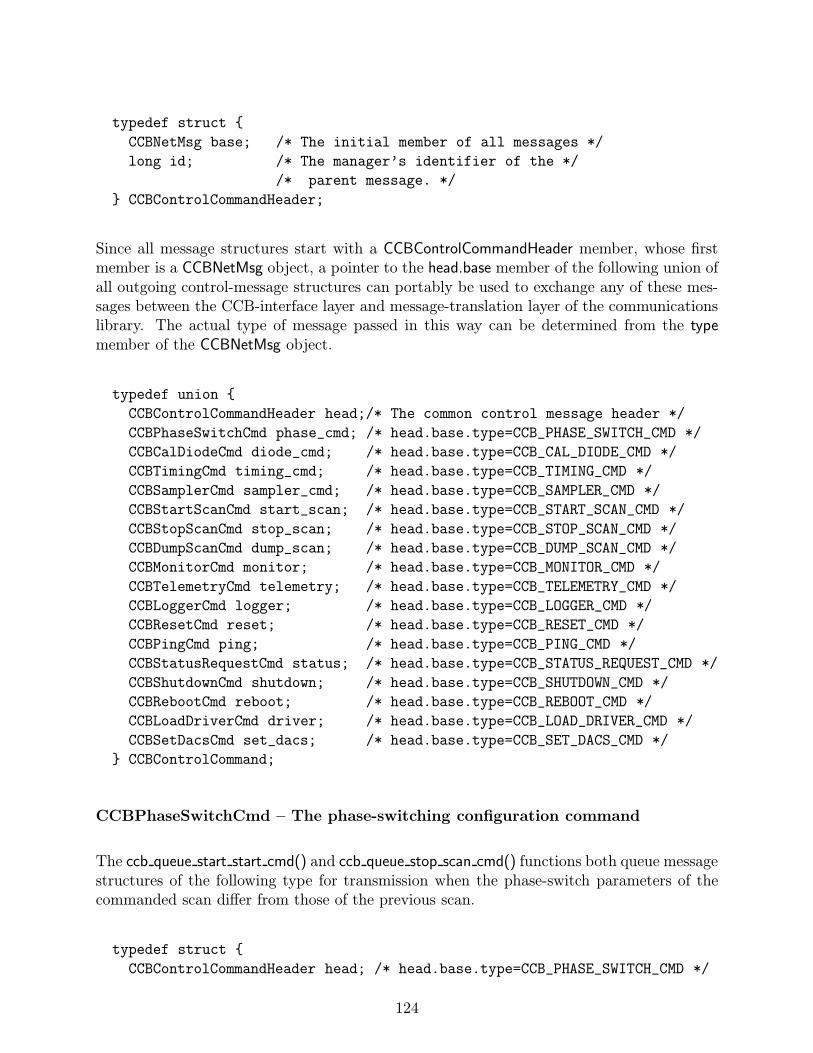
typedef struct {
CCBNetMsg base; /* The initial member of all messages */
long id; /* The manager’s identifier of the */
/* parent message. */
} CCBControlCommandHeader;
Since all message structures start with a CCBControlCommandHeader member, whose firstmember is a CCBNetMsg object, a pointer to the head.base member of the following union ofall outgoing control-message structures can portably be used to exchange any of these mes-sages between the CCB-interface layer and message-translation layer of the communicationslibrary. The actual type of message passed in this way can be determined from the typemember of the CCBNetMsg object.
typedef union {
CCBControlCommandHeader head;/* The common control message header */
CCBPhaseSwitchCmd phase_cmd; /* head.base.type=CCB_PHASE_SWITCH_CMD */
CCBCalDiodeCmd diode_cmd; /* head.base.type=CCB_CAL_DIODE_CMD */
CCBTimingCmd timing_cmd; /* head.base.type=CCB_TIMING_CMD */
CCBSamplerCmd sampler_cmd; /* head.base.type=CCB_SAMPLER_CMD */
CCBStartScanCmd start_scan; /* head.base.type=CCB_START_SCAN_CMD */
CCBStopScanCmd stop_scan; /* head.base.type=CCB_STOP_SCAN_CMD */
CCBDumpScanCmd dump_scan; /* head.base.type=CCB_DUMP_SCAN_CMD */
CCBMonitorCmd monitor; /* head.base.type=CCB_MONITOR_CMD */
CCBTelemetryCmd telemetry; /* head.base.type=CCB_TELEMETRY_CMD */
CCBLoggerCmd logger; /* head.base.type=CCB_LOGGER_CMD */
CCBResetCmd reset; /* head.base.type=CCB_RESET_CMD */
CCBPingCmd ping; /* head.base.type=CCB_PING_CMD */
CCBStatusRequestCmd status; /* head.base.type=CCB_STATUS_REQUEST_CMD */
CCBShutdownCmd shutdown; /* head.base.type=CCB_SHUTDOWN_CMD */
CCBRebootCmd reboot; /* head.base.type=CCB_REBOOT_CMD */
CCBLoadDriverCmd driver; /* head.base.type=CCB_LOAD_DRIVER_CMD */
CCBSetDacsCmd set_dacs; /* head.base.type=CCB_SET_DACS_CMD */
} CCBControlCommand;
CCBPhaseSwitchCmd – The phase-switching configuration command
The ccb queue start start cmd() and ccb queue stop scan cmd() functions both queue messagestructures of the following type for transmission when the phase-switch parameters of thecommanded scan differ from those of the previous scan.
typedef struct {
CCBControlCommandHeader head; /* head.base.type=CCB_PHASE_SWITCH_CMD */
124
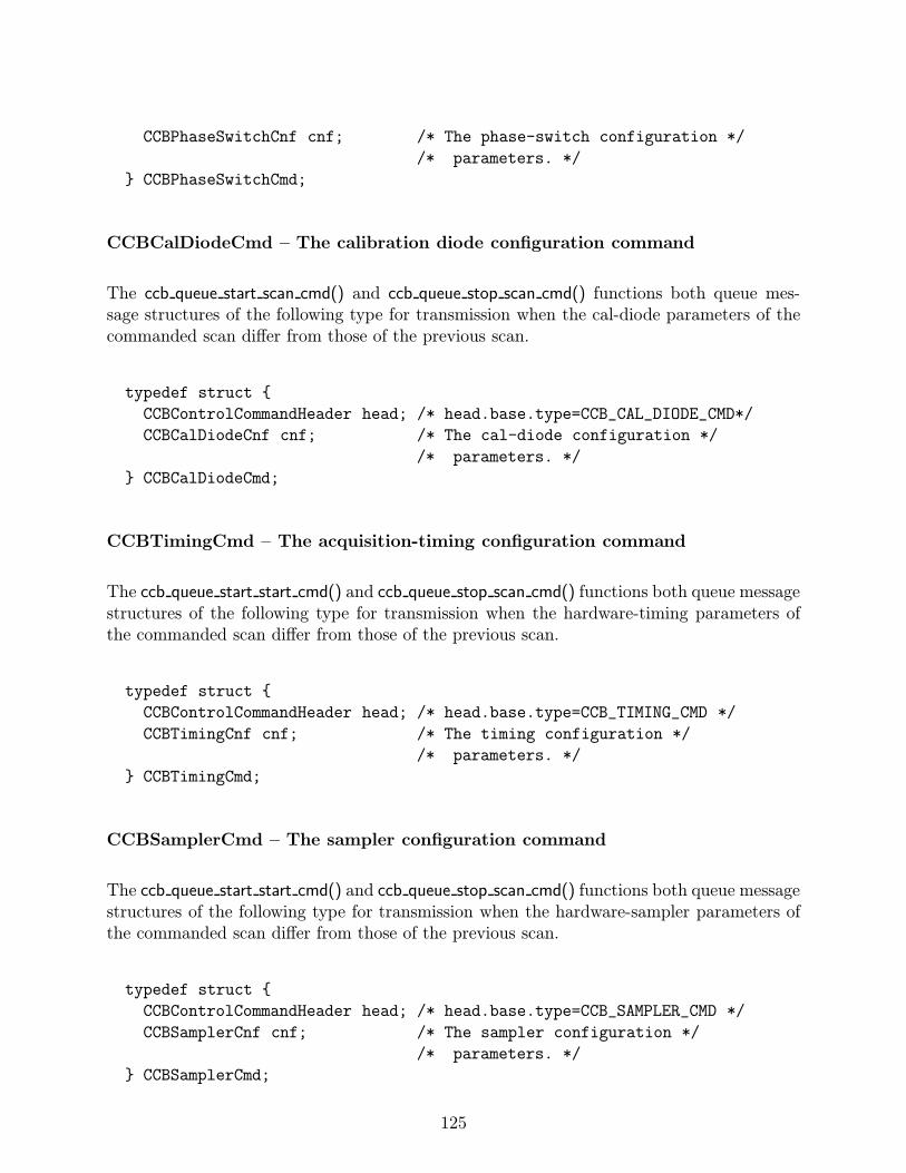
CCBPhaseSwitchCnf cnf; /* The phase-switch configuration */
/* parameters. */
} CCBPhaseSwitchCmd;
CCBCalDiodeCmd – The calibration diode configuration command
The ccb queue start scan cmd() and ccb queue stop scan cmd() functions both queue mes-sage structures of the following type for transmission when the cal-diode parameters of thecommanded scan differ from those of the previous scan.
typedef struct {
CCBControlCommandHeader head; /* head.base.type=CCB_CAL_DIODE_CMD*/
CCBCalDiodeCnf cnf; /* The cal-diode configuration */
/* parameters. */
} CCBCalDiodeCmd;
CCBTimingCmd – The acquisition-timing configuration command
The ccb queue start start cmd() and ccb queue stop scan cmd() functions both queue messagestructures of the following type for transmission when the hardware-timing parameters ofthe commanded scan differ from those of the previous scan.
typedef struct {
CCBControlCommandHeader head; /* head.base.type=CCB_TIMING_CMD */
CCBTimingCnf cnf; /* The timing configuration */
/* parameters. */
} CCBTimingCmd;
CCBSamplerCmd – The sampler configuration command
The ccb queue start start cmd() and ccb queue stop scan cmd() functions both queue messagestructures of the following type for transmission when the hardware-sampler parameters ofthe commanded scan differ from those of the previous scan.
typedef struct {
CCBControlCommandHeader head; /* head.base.type=CCB_SAMPLER_CMD */
CCBSamplerCnf cnf; /* The sampler configuration */
/* parameters. */
} CCBSamplerCmd;
125

CCBStartScanCmd – The start-scan command
The ccb queue start scan cmd() function queues message structures of the following type,ready for later exchange with the message translation layer.
typedef struct {
CCBControlCommandHeader head; /* head.base.type=CCB_START_SCAN_CMD */
unsigned long scan; /* The numeric ID to give the new */
/* scan. */
unsigned long mjd; /* The MJD UTC day number */
unsigned long tod; /* The time of day (seconds since */
/* 0H UTC). */
} CCBStartScanCmd;
CCBStopScanCmd – The stop-scan command
The ccb queue stop scan cmd() function queues message structures of the following type,ready for later exchange with the message translation layer.
typedef struct {
CCBControlCommandHeader head; /* head.base.type=CCB_STOP_SCAN_CMD */
unsigned long scan; /* The numeric ID to give the new */
/* intra-scan. */
} CCBStopScanCmd;
CCBDumpScanCmd – The dump-scan command
The ccb queue dump scan cmd() function queues message structures of the following type,ready for later exchange with the message translation layer.
typedef struct {
CCBControlCommandHeader head; /* head.base.type=CCB_DUMP_SCAN_CMD */
unsigned long scan; /* The numeric ID to give the new */
/* intra-scan. */
unsigned short adc; /* The ADC to dump */
unsigned long samples; /* The max number of samples to */
/* collect per integration. */
unsigned long frames; /* The number of per-integration */
/* data-frames to deliver. */
} CCBDumpScanCmd;
126

CCBMonitorCmd – The monitor command
The ccb queue monitor cmd() function queues message structures of the following type, readyfor later exchange with the message translation layer.
typedef struct {
CCBControlCommandHeader head; /* head.base.type=CCB_MONITOR_CMD */
unsigned short period; /* The interval between monitoring */
/* updates. */
} CCBMonitorCmd;
CCBTelemetryCmd – The telemetry command
The ccb queue telemetry cmd() function queues message structures of the following type,ready for later exchange with the message translation layer.
typedef struct {
CCBControlCommandHeader head; /* head.base.type=CCB_TELEMETRY_CMD */
unsigned short streams; /* The telemetry-streams to report */
} CCBTelemetryCmd;
CCBLoggerCmd – The logger command
The ccb queue logger cmd() function queues message structures of the following type, readyfor later exchange with the message translation layer.
typedef struct {
CCBControlCommandHeader head; /* head.base.type=CCB_LOGGER_CMD */
unsigned long period; /* The interval at which */
/* historical log messages are */
/* forgotten (seconds). */
} CCBLoggerCmd;
CCBResetCmd – The reset command
The ccb queue reset cmd() function queues message structures of the following type, readyfor later exchange with the message translation layer.
127

typedef struct {
CCBControlCommandHeader head; /* head.base.type=CCB_RESET_CMD */
} CCBResetCmd;
CCBPingCmd – The ping command
The ccb queue ping cmd() function queues message structures of the following type, readyfor later exchange with the message translation layer.
typedef struct {
CCBControlCommandHeader head; /* head.base.type=CCB_PING_CMD */
} CCBPingCmd;
CCBStatusRequestCmd – The status-request command
The ccb queue status request cmd() function queues message structures of the following type,ready for later exchange with the message translation layer.
typedef struct {
CCBControlCommandHeader head; /* head.base.type = */
/* CCB_STATUS_REQUEST_CMD */
} CCBStatusRequestCmd;
CCBShutdownCmd – The shutdown command
The ccb queue shutdown cmd() function queues message structures of the following type,ready for later exchange with the message translation layer.
typedef struct {
CCBControlCommandHeader head; /* head.base.type=CCB_SHUTDOWN_CMD */
} CCBShutdownCmd;
CCBRebootCmd – The reboot command
The ccb queue reboot cmd() function queues message structures of the following type, readyfor later exchange with the message translation layer.
128

typedef struct {
CCBControlCommandHeader head; /* head.base.type=CCB_REBOOT_CMD */
} CCBRebootCmd;
CCBLoadDriverCmd – The load-driver command
The ccb queue load driver cmd() function queues message structures of the following type,ready for later exchange with the message translation layer.
typedef struct {
CCBControlCommandHeader head; /* head.base.type=CCB_LOAD_DRIVER_CMD */
unsigned short type; /* A CCBDriverType enumerator */
} CCBLoadDriverCmd;
CCBSetDacsCmd – The set-dacs command
The ccb queue set dacs cmd() function queues message structures of the following type, readyfor later exchange with the message translation layer.
typedef struct {
CCBControlCommandHeader head; /* head.base.type=CCB_SET_DACS_CMD */
unsigned short counts[CCB_GPIO_NDAC]; /* The count inputs of the */
/* digital-to-analog */
/* converters. */
} CCBSetDacsCmd;
6.2.2 The message structures of incoming control-link replies
For incoming messages sent by the CCB server to the manager over the control-link, theCCB-interface layer enumerates the known types of reply message as follows.
typedef enum {
CCB_CNTRL_PING_REPLY, /* A ping reply */
CCB_STATUS_REPLY, /* A status-request reply */
CCB_CNTRL_CMD_ACK /* A control command-acknowledgement reply */
} CCBControlReplyType;
The first member of all control-reply message structures is a CCBControlReplyHeader struc-ture.
129
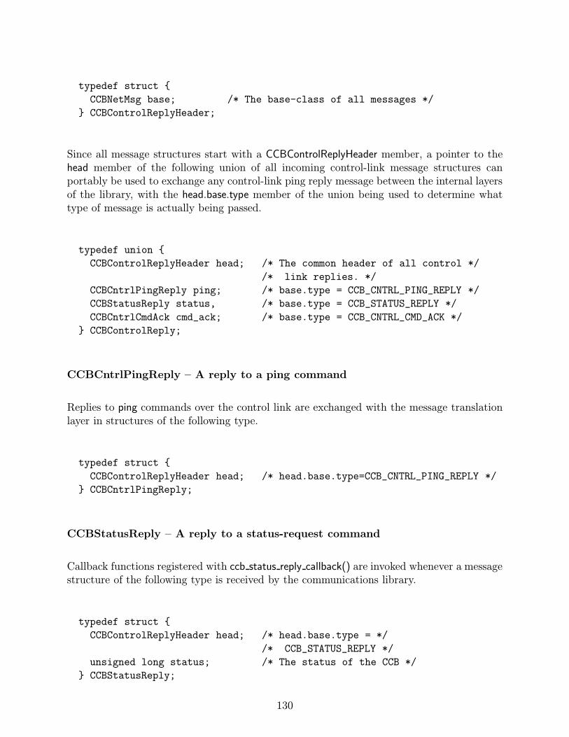
typedef struct {
CCBNetMsg base; /* The base-class of all messages */
} CCBControlReplyHeader;
Since all message structures start with a CCBControlReplyHeader member, a pointer to thehead member of the following union of all incoming control-link message structures canportably be used to exchange any control-link ping reply message between the internal layersof the library, with the head.base.type member of the union being used to determine whattype of message is actually being passed.
typedef union {
CCBControlReplyHeader head; /* The common header of all control */
/* link replies. */
CCBCntrlPingReply ping; /* base.type = CCB_CNTRL_PING_REPLY */
CCBStatusReply status, /* base.type = CCB_STATUS_REPLY */
CCBCntrlCmdAck cmd_ack; /* base.type = CCB_CNTRL_CMD_ACK */
} CCBControlReply;
CCBCntrlPingReply – A reply to a ping command
Replies to ping commands over the control link are exchanged with the message translationlayer in structures of the following type.
typedef struct {
CCBControlReplyHeader head; /* head.base.type=CCB_CNTRL_PING_REPLY */
} CCBCntrlPingReply;
CCBStatusReply – A reply to a status-request command
Callback functions registered with ccb status reply callback() are invoked whenever a messagestructure of the following type is received by the communications library.
typedef struct {
CCBControlReplyHeader head; /* head.base.type = */
/* CCB_STATUS_REPLY */
unsigned long status; /* The status of the CCB */
} CCBStatusReply;
130

CCBCntrlCmdAck – An acknowledgment to a control command
Whenever a message structure of the following type is received by the communications library,if the status member is anything other than CCB CMD ACCEPTED, then the library invokesthe callback that the manager previously provided when it called ccb cmd error callback().
typedef struct {
CCBControlReplyHeader head; /* head.base.type=CCB_CNTRL_CMD_ACK */
unsigned long id; /* The manager-specified ID of */
/* the command that is being */
/* acknowledged. */
unsigned long status; /* A CCBCmdStatus enumerator */
} CCBCntrlCmdAck;
6.2.3 The message structures of incoming telemetry messages
This section documents the data structures that are exchanged between the CCB interfacelayer and the message translation layer at both ends of the telemetry link. The CCB interfacelayer defines the following enumeration to distinguish between the various message typesencoded in these message structures.
typedef enum {
CCB_INTEG_MSG, /* An integration data message */
CCB_MONITOR_MSG, /* A monitoring data message */
CCB_LOG_MSG, /* A log message */
CCB_TELEM_PING_REPLY /* A reply to a ping command */
} CCBTelemetryType;
The first member of all telemetry message structures is a CCBTelemetryHeader structure,which is defined as follows.
typedef struct {
CCBNetMsg base; /* The base-class of all messages */
unsigned long mjd; /* The MJD UTC day number */
unsigned long sec; /* The time of day (seconds since 0H UTC) */
unsigned long ns; /* The number of nanoseconds from */
/* the start of the specified second. */
} CCBTelemetryHeader;
131

Note that the obligatory CCBNetMsg member of all network messages is the first member ofthis structure. The remaining members report the date and time at which the message wasgenerated.
Since all telemetry message structures start with a CCBTelemetryHeader member, a pointerto the head member of the following union can be used as a pointer to any type of telemetrymessage. The base.type member of this header can then be used to determine which type oftelemetry message the pointer actually refers to.
typedef union {
CCBTelemetryHeader head; /* The common telemetry header */
CCBIntegMsg integ; /* An integration data message */
CCBMonitorMsg monitor; /* A monitor data message */
CCBLogMsg log; /* A log message */
CCBTelemPingReply ping; /* A reply to a ping command */
} CCBTelemetryMessage;
The data-structures within this union, are declared as follows.
CCBIntegMsg – Integration data messages
Callback functions registered with ccb integ msg callback() are invoked whenever a messagestructure of the following type is received by the communications library over the telemetrylink.
typedef struct {
CCBTelemetryHeader head; /* head.base.type=CCB_INTEG_MSG */
unsigned long scan; /* The number of the parent scan */
unsigned long id; /* The integration ID */
unsigned short flags; /* Single-bit status flags */
unsigned long data[CCB_MAX_INTEG]; /* The integrated data */
} CCBIntegMsg;
CCBMonitorMsg – Monitor data messages
Callback functions registered with ccb monitor msg callback() are invoked whenever a mes-sage structure of the following type is received by the communications library over thetelemetry link.
typedef struct {
132

CCBTelemetryHeader head; /* head.base.type=CCB_MONITOR_MSG */
unsigned long scan; /* The scan number */
unsigned long id; /* The monitor ID */
unsigned short fan12v; /* The voltage of the 12V fan PSU */
unsigned short a8v; /* The voltage of the analog 8V PSU */
unsigned short d5v; /* The voltage of the digital 5V PSU */
unsigned short cnf_done; /* True if the FPGAs have been programmed */
unsigned short high_temp; /* True if the CCB enclosure is too hot */
unsigned short ccb_id; /* The 2-bit ID of the CCB hardware */
/*
* The following members are specific to each FPGA, and are thus arrays
* of one value per FPGA.
*/
unsigned short fpga_d1_2v[CCB_NUM_FPGA]; /* The digital 1.2V PSU */
/* voltage. */
unsigned short fpga_d2_5v[CCB_NUM_FPGA]; /* The digital 2.5V PSU */
/* voltage. */
unsigned short fpga_d3_3v[CCB_NUM_FPGA]; /* The digital 3.3V PSU */
/* voltage. */
unsigned short fpga_a5v[CCB_NUM_FPGA]; /* The analog 5V PSU */
/* voltage. */
unsigned short fpga_hb[CCB_NUM_FPGA]; /* The mean heartbeat */
/* voltage. */
unsigned short fpga_cnf_error[CCB_NUM_FPGA];/* Firmware checksum */
/* error. */
unsigned short fpga_cnf_done[CCB_NUM_FPGA]; /* FPGA programmed */
} CCBMonitorMsg;
CCBLogMsg – CCB log messages
Callback functions registered with ccb log msg callback() are invoked whenever a messagestructure of the following type is received by the communications library over the telemetrylink.
#define CCB_MAX_LOG 128 /* The maximum length of a log */
/* message. */
typedef struct {
CCBTelemetryHeader head; /* head.base.type=CCB_LOG_MSG */
char msg[CCB_MAX_LOG]; /* The message to be logged */
unsigned long id; /* A unique message identifier */
unsigned short level; /* The severity level of the message */
} CCBLogMsg;
133
CCBTelemPingReply – A reply to a ping command
Replies to ping commands over the telemetry link are exchanged with the message translationlayer in structures of the following type.
typedef struct {
CCBTelemetryHeader head; /* head.base.type=CCB_TELEM_PING_REPLY */
} CCBTelemPingReply;
6.3 Sending network messages
As mentioned earlier, output control messages are queued for transmission in a queueof message structures, then dispatched to the server by one or more calls to ccb client-communicate(). While ccb client communicate() is running, if the I/O layer finishes trans-mitting a message, the message-translation layer does the following.
1. It removes the message structure of the next oldest message from the queue.
2. It then calls a function in the packet-buffer layer which:
(a) Clears the output buffer and resets its read and write pointers to point to thestart of the buffer.
(b) Writes a zero-valued big-endian byte-count in the first 4 bytes of the buffer.
(c) Writes the enumerated type of the message, as passed to it by the message-translation layer, expressed as an unsigned 2-byte big-endian integer.
(d) Increments the buffer write-pointer to point to the byte following the above twoitems.
3. For each member within the message structure, the message-translation layer then callsa function in the API of the packet-buffer layer, chosen according to the type of thestructure member, to have the value of the member appended to the current messagewithin the buffer. These functions all increment the buffer write-pointer to point tothe byte in the buffer which follows the data that they appended.
4. Once all structure members have been packed into the buffer, the message-translationlayer then calls a function of the packet-buffer API to terminate the message in thebuffer. This function replaces the zero-valued byte-count at the start of the buffer withthe count of the actual number of bytes used by the message in the buffer.
5. Finally, the message-translation layer calls a function in the I/O layer to start writingthe contents of the buffer to the control socket. As the I/O layer does this, it increments
134

the read-pointer of the packet-buffer, so that it knows from where to resume if the socketblocks when non-blocking I/O is in use. If it completes writing the latest message, itgoes back to step one, to get the next unsent message. Otherwise, it returns control tothe manager, and tells the manager to call ccb client communicate() again when outputagain becomes possible, so that it can resume sending the current message.
6.4 Receiving network messages
As already documented, messages are read from the telemetry port of the server by callingccb client communicate(). At the start of reading each new message, this function does thefollowing:
1. It tells the packet-buffer layer of the telemetry connection to clear its input buffer.This also resets the read and write pointers of the buffer to point to its first byte.
2. It instructs the I/O layer to attempt to read the initial 4 byte, byte count into themessage buffer.
3. In practice, if non-blocking I/O is in effect, a few calls may be needed to ccb client-communicate() before the byte count is completely read.
4. Once the I/O layer has the byte count, it knows how many more bytes it will need toread to acquire the new message.
5. The I/O layer then attempts to read the rest of the message. Again, this may requiremultiple calls to ccb client communicate() when non-blocking I/O is being used.
6. Once the message has been completely read into the input packet-buffer, the messagetranslation layer then decodes the message-type enumeration that follows the bytecount, and uses this to identify the type of the message within its table of messagedefinitions.
7. According to the member descriptions in the definition of the message, the message-translation layer now calls the appropriate datatype-specific functions in the packet-buffer layer to decode the values of each member of the message, and records the resultsin an internal message structure.
8. The completed message structure is then passed up to ccb client communicate(), whichinvokes the corresponding callback function to deliver the contents of the message tothe manager.
The equivalent procedure is of course performed for the replies received over the control link,and this uses all of the same functions, except that different callback functions are called todeliver messages to the manager.
135

Chapter 7
The CCB dump-data communicationsAPI
Programs which read dump-mode data from the CCB server while the CCB server is underthe control of the CCB manager or the ccb demo client program, can be written by usingfunctions that are provided by the libccbdump library.
This provides a very simple interface to the dump-mode TCP/IP port of the CCB server.The following is a simple example of a program that uses this interface.
#include <stdlib.h>
#include <stdio.h>
#include "ccbdump.h"
int main(int argc, char *argv[])
{
CCBDumpReader *dr; /* The object which manages the network connection */
CCBDumpFrame f; /* A dump-mode frame of data */
const char *host; /* The CCB host-computer to contact */
int i;
/*
* Get the name of the computer on which the CCB server is running,
* from the command line.
*/
if(argc == 2) {
host = argv[1];
} else {
fprintf(stderr, "Usage: %s <hostname>\n", argv[0], host);
return 1;
136

};
/*
* Connect to the CCB server that is running on the specified
* computer. This function call returns an opaque object, which
* manages the open connection to the CCB server’s dump-mode port.
*/
dr = new_CCBDumpReader(host);
if(!dr)
return 1;
/*
* Read one dump-mode frame of data at a time, and display its
* contents to standard output.
*/
while(ccb_read_dump_frame(dr, &f)==0) {
/*
* Display items from the header.
*/
printf("Scan=%lu Integ=%lu flags=%hu pswlen=%hu nsample=%hu\n",
f.scan, f.integ, f.flags, f.pswlen, f.nsample);
/*
* Display the individual dump-mode samples of the frame.
*/
for(i=0; i<f.nsample; i++) {
unsigned long sample = f.samples[i];
/*
* Print the sample number, within the frame.
*/
printf("%2d: ", i);
/*
* Is the overflow bit set?
*/
if((sample & CCB_ADC_OVERFLOW_MASK) != 0)
printf("(overflowed)\n");
else
printf("%05ld\n", sample);
};
};
/*
* Disconnect from the dump-mode server.
*/
dr = del_CCBDumpReader(dr);
return 0;
}
137

Assuming that the CCB include files are installed in /usr/local/include/ and the CCB librariesare installed in /usr/local/lib, and that the above code is placed in a file called test demo.cthis program could be compiled and linked by typing:
gcc -o test_demo test_demo.c -I/usr/local/include -L/usr/local/lib \
-Xlinker -R/usr/local/lib -lccbdump
The program would then be run like:
./test_demo ccblab.gb.nrao.edu
7.1 Functions in the libccbdump library
The functions in the library are defined as follows.
7.1.1 new CCBDumpReader()
This function opens a connection to the dump-mode port of the CCB server process, ona specified computer, and returns an opaque object that should be used for subsequentcommunication with that server.
It’s function-prototype is as follows:
CCBDumpReader *new_CCBDumpReader(const char *host);
It’s sole argument is a string containing the name or IP-address of the computer where theCCB server is running. If it succeeds in opening a connection to the server, then it returnsa non-NULL pointer, which should subsequently be passed to other functions in the library,to communicate with the server.
On error, this function returns NULL, after writing an error message to the standard-erroroutput-stream.
7.1.2 get CCBDumpReader fd()
Once a connection to a CCB server has been opened by a call to new CCBDumpReader() theget CCBDumpReader fd() function can optionally be used to find out which file descriptor
138

dump-mode data will be arriving on. This is only intended to be used by programs thatuse the select() system call to watch for the arrival of data. It should not be used by theprogram to read or write data, other than through the ccb read dump frame() function.
It’s function-prototype is as follows:
int ccb_get_CCBDumpReader_fd(CCBDumpReader *dr);
The sole argument of this function is the pointer that was returned by the preceding callto new CCBDumpReader(). If the argument is NULL, then the returned value will be -1.Otherwise it will be the file descriptor of the TCP/IP connection to the server.
7.1.3 ccb read dump frame()
Once a connection to a CCB server has been opened by a call to new CCBDumpReader() theccb read dump frame() function can be called to read data from the server. Each call to thisfunction returns one frame of data from a single integration period.
It’s function-prototype is as follows:
int ccb_read_dump_frame(CCBDumpReader *dr, CCBDumpFrame *f);
Its first argument is the pointer that was returned by the preceding call to new CCBDumpReader().Its second argument is a pointer to the variable in which to store the received frame of data.Its return value is 0 if new data were read, or 1 if an unrecoverable error occurred, such asthe loss of the connection to the server.
The contents of CCBDumpFrame variables have already been described in section 5.7.3.
Macros are provided for deducing the states of the phase-switches in each sample. Forexample, if the CCBDumpFrame variable, whose pointer was passed to ccb read dump frame(),were called df, and one wanted to know what the states of phase switches A and B were,when element i of df.samples[] was acquired, then one would type:
int state_of_switch_a, state_of_switch_b;
...
state_of_switch_a = CCB_DUMP_PHASE_A(df, i);
state_of_switch_b = CCB_DUMP_PHASE_B(df, i);
When these macros return 0, this means that the phase-switch was open. When they return1, this means that the phase-switch was closed.
139

7.1.4 del CCBDumpReader()
This function closes a previously opened connection to the dump-mode port of the CCBserver process, relinquishes the resources that were used to communicate with it, and returnsNULL.
It’s function-prototype is as follows:
CCBDumpReader *del_CCBDumpReader(CCBDumpReader *dr);
It’s sole argument is the pointer that was returned by a previous call to new CCBDumpReader().Note that it is legal for this to be NULL.
This function always returns NULL and is designed to be used in the following manner.
dr = del_CCBDumpReader(dr);
where dr is a CCBDumpReader pointer that was previously returned by new CCBDumpReader().By assigning the NULL return value of the function, to the pointer whose object has justbeen deleted, one will see a segmentation fault if the program subsequently incorrectly triesto continue to use the deleted object.
140
Chapter 8
The CCB diagnostic communicationsAPI
In order to facilitate the writing of new diagnostic programs, a library, libccbtestclient, hasbeen provided that can be used to configure and start scans, and read back either integratedor dump-mode data. It constitutes a simplifying layer on top of the libccbcommon, libccbclientand libccbdump libraries.
Unlike the lower level libraries, which report the arrival of data from the CCB server, bycalling asynchronous callback functions, the libccbtestclient library hides the asynchronous,non-blocking aspects of the lower-level libraries behind a simpler, synchronous, blocking API.One can thus send a command to the CCB server, to start a scan, by calling one function,and then call another function to await and acquire a frame of data from the new scan.
8.1 Functions in the libccbtestclient library
The functions in the library are defined as follows.
8.1.1 new CCBTestClient()
This function creates the resources that it needs to configure and subsequently get datafrom a CCB server, and returns a pointer to the opaque, dynamically allocated object thatcontains these resources. It’s function-prototype is:
CCBTestClient *new_CCBTestClient(const char *config);
141
It’s sole argument is a string whose contents can be used to override the values of specifiedconfiguration parameters. This can thus be used to set the initial configuration, beforeconnecting to the CCB server. See section 3.2 for a description of the format of this string.
If successful, the function returns a pointer to an opaque CCBTestClient, which containsthe resources that are needed to talk to the CCB server. This pointer should be passed tosubsequent calls to functions in the library. Note that this function doesn’t actually opena connection to a CCB server. That must be done by subsequently calling ccb tst connect-client(). On error, the function reports an error to stderr and returns NULL.
8.1.2 ccb tst connect client()
Once a CCBTestClient object has been created by a call to new CCBTestClient(), a connectionto a CCB server should be opened by calling the ccb tst connect client() function. This hasthe following function prototype:
int ccb_tst_connect_client(CCBTestClient *ctc, const char *host);
The first argument is the pointer that was returned by the preceding call to new CCBTestClient(),and the second argument is the name or IP address of the computer on which the CCB serveris running. If successful, this function returns 0. Otherwise it reports an error to stderr andreturns 1.
If this function is called when the specified CCBTestClient object is already connected toa server, then the former connection is quietly terminated via an internal call to ccb tst-disconnect client().
8.1.3 ccb tst disconnect client()
The connection of a CCBTestClient object to a CCB server can be terminated either by delet-ing the CCBTestClient object, or by calling ccb tst disconnect client(). The latter functionhas the following prototype:
void ccb_tst_disconnect_client(CCBTestClient *ctc);
Its sole argument is the pointer that was returned by the preceding call to new CCBTestClient().
Note that it is also legal to call this function when there is no connection to be terminated.
142
8.1.4 del CCBTestClient()
This function closes a previously opened connection to the CCB server, relinquishes theresources that were used to communicate with it, and returns NULL.
It’s function-prototype is as follows:
CCBTestClient *del_CCBTestClient(CCBTestClient *ctc);
It’s sole argument is the pointer that was returned by a previous call to new CCBTestClient().Note that it is legal for this to be NULL.
This function always returns NULL and is designed to be used in the following manner.
ctc = del_CCBTestClient(ctc);
where ctc is a CCBTestClient pointer that was previously returned by new CCBTestClient().By assigning the NULL return value of the function, to the pointer whose object has just beendeleted, one can expect to see a segmentation fault if the program subsequently incorrectlytries to continue to use the deleted object.
8.1.5 ccb tst update conf()
The configuration of subsequent scans can either be modified via an argument to the functionthat starts the scan, or can be modified by the ccb tst update conf() function. The twomethods can be used in conjunction, with ccb tst update conf() being used to set up theparameters that remain constant during subsequent scans, and the scan-specific parametersbeing set up when each individual scan is started. The prototype of the ccb tst update conf()function is as follows:
int ccb_tst_update_conf(CCBTestClient *ctc, const char *conf);
The first argument is the pointer that was returned by a preceding call to new CCBTestClient().The second argument is a string containing assignment specifications to any subset of thescan configuration parameters. The form of the contents of this string is described in sec-tion 3.2.
Take the following example.
ccb_tst_update_conf("integ_period=100 cal_steps=AB*5,NONE*10", cnf);
143

This would change the integ period parameter, which sets the number of phase-switch cyclesper integration-period, to have the value 100, and would configure the cal-diodes to repeat-edly cycle through a sequence of being switched on for 5 integration periods then switchedoff for 10 integration periods.
8.1.6 ccb tst start scan()
The ccb tst start scan() function tells the CCB to start an integration-mode scan. Its proto-type is as follows:
int ccb_tst_start_scan(CCBTestClient *ctc, const char *conf);
The first argument is the pointer that was returned by a preceding call to new CCBTestClient().The second argument is an optional string, containing assignment specifications to any sub-set of the scan configuration parameters. These configuration changes will take affect whenthe new scan starts. Unspecified parameters retain the values that they had in the previousscan, except where modified by an intervening call to ccb tst update conf().
If the arguments are valid, and a connection exists to the CCB server, then the function willqueue the request to start the scan, to be sent to the server, and return 0. Otherwise it willreport an error to stderr and return 1.
Once this function has been called, integrated data from the scan can be received by callingthe ccb tst read integ frame() function. Beware that the queued request to start the scandoesn’t actually get sent until ccb tst read integ frame() is called, since the underlying event-loop only runs when waiting for data to arrive.
8.1.7 ccb tst read integ frame()
Once ccb tst start integ() has been called, to tell the CCB to start a integration-mode scan,the ccb tst read integ frame() function can be called to read back one frame of integrateddata at a time. Its prototype is as follows:
int ccb_tst_read_integ_frame(CCBTestClient *ctc, CCBIntegFrame *integ);
The first argument is the pointer that was returned by a preceding call to new CCBTestClient().The second argument must be a pointer to the variable into which the received data shouldbe copied. The data-type of this variable is described in section 5.7.2.
144
If the connection to the CCB server is lost, or one of the arguments is NULL, or no integration-mode scan has been started, then ccb tst read integ frame() reports an error to stderr, andreturns 1. Otherwise, once an integration-mode frame of data from the most recently re-quested scan, arrives from the CCB server, the function returns the received data in thevariable pointed to by the integ argument, and returns 0, to indicate success.
Beware that the CCB server discards any integration-mode frames that arrive while a previ-ous frame is still being dispatched to the CCB manager. Thus when the integration-periodis short, then the manager may not receive every integration-mode frame that is acquiredby the CCB.
8.1.8 ccb tst start dump()
The ccb tst start dump() function tells the CCB to start a dump-mode scan. Its prototypeis as follows:
int ccb_tst_start_dump(CCBTestClient *ctc, const char *conf,
unsigned short adc, unsigned long samples,
unsigned long frames);
The first argument is the pointer that was returned by a preceding call to new CCBTestClient().The second argument is an optional string, containing assignment specifications to any sub-set of the scan configuration parameters. These configuration changes will take affect whenthe dump-scan starts. Unspecified parameters retain the values that they had in the previousscan, except where modified by an intervening call to ccb tst update conf().
The third argument specifies from which of the CCB ADC-inputs, the samples should beacquired, and must be a number between 0 and CCB NUM ADC-1. An ADC designation of0 corresponds to the input whose label on the front panel is J1.
The fourth argument specifies how many samples to acquire per integration period. If therequested number exceeds the maximum of CCB DUMP MAX SAMPLES (currently 16383),then the number returned will be equal to this maximum.
Finally, the fifth argument specifies for how many integration periods of dump-mode framesshould be sent to the program. Beware that the CCB server discards dump-mode framesthat are generated while a previous dump-mode frame is still being dispatched to a clientprogram. Thus if you ask for a particular number of frames, although you will receive thespecified number of frames, they may not be from contiguous integration periods. To tell theCCB server to keep sending dump-mode frames indefinitely, specify the value CCB DUMP-ALL FRAMES.
145

If the arguments are valid, and a connection exists to the CCB server, then the function willqueue the request to start the scan, to be sent to the server, and return 0. Otherwise it willreport an error to stderr and return 1.
Once this function has been called, dump-mode data from the scan can be received bycalling the ccb tst read dump frame() function. Beware that the queued request to start thescan doesn’t actually get sent until ccb tst read dump frame() is called, since the underlyingevent-loop only runs when waiting for data to arrive.
8.1.9 ccb tst read dump frame()
Once ccb tst start dump() has been called, to tell the CCB to start a dump-mode scan, theccb tst read dump frame() function can be called to read back one dump-mode frame of dataat a time. Its prototype is as follows:
int ccb_tst_read_dump_frame(CCBTestClient *ctc, CCBDumpFrame *dump);
The first argument is the pointer that was returned by a preceding call to new CCBTestClient().The second argument must be a pointer to the variable into which the received data shouldbe copied. Note that the CCBDumpFrame datatype is described in section 7.1.3.
If the connection to the CCB server is lost, or one of the arguments is NULL, or no dump-mode scan has been started, then ccb tst read dump frame() reports an error to stderr, andreturns 1. Otherwise, once a dump-mode frame of data, from the most recently requestedscan, arrives from the CCB server, the function returns the received data in the variablepointed to by the dump argument, and returns 0, to indicate success.
Beware that the CCB server discards any dump-mode frames that arrive while a previousframe is still be dispatched to a dump-mode client. Thus when the integration-period is short,a dump-mode client program may not receive every dump-mode frame that is acquired bythe CCB.
8.1.10 ccb tst mean of dump()
This function can be used to compute the mean and RMS of the samples within a dump framethat has previously been read from the CCB by the ccb tst read dump frame() function. Itsprototype is as follows:
int ccb_tst_mean_of_dump(CCBDumpFrame *dump, double *mean,
double *rms, unsigned *n);
146

The first argument is a pointer to a dump-frame object that was filled in by a previous callto ccb tst read dump frame(). The remaining arguments should be pointers to the variableswhere the results should be returned. The function assigns the arithmetic mean of thesamples in the dump-mode frame, to *mean, the root-mean-square deviation of the samplesfrom this mean level, to *rms, and the number of unsaturated samples that contributed tothe mean and RMS, to *n.
Note that only samples that don’t have their overflow bits set, are included in the mean.Thus if all of the samples are saturated, then ccb tst mean of dump() returns non-zero, toindicate that it wasn’t able to compute the mean. Otherwise it returns 0, to indicate success.
8.1.11 ccb tst get config()
For cases where the use of a string to specify changes to the configuration, is inefficientor awkward, the ccb tst get config() function can be used to get a pointer to the objectthat contains the binary configuration. This pointer can then be used with functions fromlibccbcommon, such as ccb get timing cnf() and ccb set config() to modify the configurationthat will be used by subsequently started scans. The prototype of ccb tst get config() is asfollows:
CCBConfig *ccb_tst_get_config(CCBTestClient *ctc);
The only argument is the pointer that was returned by a preceding call to new CCBTestClient().
8.1.12 ccb tst set dacs()
This function can be used to set the voltages of the analog outputs of the GPIO card.Although these outputs aren’t currently used for anything by the CCB, they can be usedto generate known voltages for DC input tests, as in the ccb test dc response program. Thefunction prototype of ccb tst set dacs() is as follows:
int ccb_tst_set_dacs(CCBTestClient *ctc,
unsigned short counts[CCB_GPIO_NDAC]);
The first argument is the pointer that was returned by a preceding call to new CCBTestClient().For an explanation of the second argument please see the documentation of the ccb queue-set dacs cmd() function, in section 4.11.1.
147

Index
Function indexccb add intervals() . . . . . . . . . . 47ccb add to timestamp() . . . . . . . 54ccb cal cycle length() . . . . . . . . 51ccb calibrate monitor data() . . . . . 59ccb check config . . . . . . . . . . . 28ccb client communicate() . . . . . . 69ccb client connect() . . . . . . . . . 67ccb client disconnect() . . . . . . . . 68ccb client poll args() . . . . . . . . . 71ccb client select args() . . . . . . . . 70ccb client non blocking io() . . . . . 69ccb client selected io() . . . . . . . . 71ccb client sockets callback() . . . . . 72ccb clock interval() . . . . . . . . . 48ccb cmd error callback() . . . . . . . 73ccb compare intervals() . . . . . . . 47ccb compare timestamps() . . . . . . 53ccb compute led states() . . . . . . . 61ccb compute mode led states() . . . . 61ccb copy config() . . . . . . . . . . 28ccb cycle length() . . . . . . . . . . 49ccb default config() . . . . . . . . . 28ccb diff config() . . . . . . . . . . . 28ccb fake integrations() . . . . . . . . 55ccb get cal diode cnf() . . . . . . . . 33ccb get CCBDumpReader fd . . . . . 139ccb get phase switch cnf() . . . . . . 31ccb get sampler cnf() . . . . . . . . 39ccb get timestamp() . . . . . . . . . 53ccb get timing cnf() . . . . . . . . . 37ccb hms of timestamp() . . . . . . . 55ccb integ msg callback() . . . . . . . 90ccb integ per interval() . . . . . . . 51ccb integration duration() . . . . . . 50ccb integration time() . . . . . . . . 50ccb interval is zero() . . . . . . . . . 48
ccb log msg callback() . . . . . . . . 93ccb log server msg() . . . . . . . . . 116ccb monitor msg callback() . . . . . 89ccb parse CCBCalDiodes . . . . . . . 44ccb parse CCBConfig() . . . . . . . . 41ccb parse CCBPhaseSwitches . . . . . 43ccb phase switch sequence . . . . . . 115ccb ping echos() . . . . . . . . . . . 82ccb print CCBConfig() . . . . . . . . 42ccb queue dump frame msg() . . . . 114ccb queue dump scan cmd() . . . . . 78ccb queue integ msg() . . . . . . . . 113ccb queue load driver cmd() . . . . . 80ccb queue logger cmd() . . . . . . . 81ccb queue monitor cmd() . . . . . . 80ccb queue monitor msg() . . . . . . 113ccb queue ping cmd() . . . . . . . . 82ccb queue reboot cmd() . . . . . . . 83ccb queue reset cmd() . . . . . . . . 81ccb queue set dacs cmd() . . . . . . 84ccb queue shutdown cmd() . . . . . . 83ccb queue start scan cmd() . . . . . 76ccb queue status request cmd() . . . 83ccb queue stop scan cmd() . . . . . . 77ccb queue telemetry cmd() . . . . . . 80ccb read CCBConfig() . . . . . . . . 41ccb read dump frame() . . . . . . . 139ccb render CCBCalDiodes . . . . . . 44ccb render CCBPhaseSwitches . . . . 43ccb scale interval() . . . . . . . . . 46ccb scan duration() . . . . . . . . . 50ccb server event loop() . . . . . . . . 112ccb set cal diode cnf() . . . . . . . . 32ccb set config() . . . . . . . . . . . 29ccb set phase switch cnf() . . . . . . 29ccb set sampler cnf() . . . . . . . . 38ccb set timing cnf() . . . . . . . . . 34
148

ccb settling time() . . . . . . . . . . 49ccb status reply callback() . . . . . . 86ccb subtract intervals() . . . . . . . 47ccb time to timestamp() . . . . . . . 54ccb time until() . . . . . . . . . . . 53ccb tst connect client() . . . . . . . 142ccb tst disconnect client() . . . . . . 142ccb tst get config() . . . . . . . . . 147ccb tst mean of dump() . . . . . . . 146ccb tst read dump frame() . . . . . . 146ccb tst read integ frame() . . . . . . 144ccb tst set dacs() . . . . . . . . . . 147ccb tst start dump() . . . . . . . . . 145ccb tst start scan() . . . . . . . . . 144ccb tst update conf() . . . . . . . . 143ccb write CCBConfig() . . . . . . . . 42ccb zero dump frame() . . . . . . . . 115ccb zero integ frame() . . . . . . . . 114ccb zero interval() . . . . . . . . . . 48ccb zero timestamp() . . . . . . . . 53del CCBClientLink() . . . . . . . . . 68del CCBConfig() . . . . . . . . . . . 27del CCBDumpReader() . . . . . . . . 140del CCBServerDriver() . . . . . . . . 111del CCBServerLink() . . . . . . . . . 111del CCBTestClient() . . . . . . . . . 143new CCBClientLink() . . . . . . . . 66new CCBConfig() . . . . . . . . . . 27new CCBDumpReader() . . . . . . . 138new CCBServerDriver() . . . . . . . 105new CCBServerLink() . . . . . . . . 104new CCBTestClient() . . . . . . . . 141
Datatype indexCCBCalDiodeCmd . . . . . . . . . . 125CCBCalDiodeCnf . . . . . . . . . . 33CCBCalDiodes . . . . . . . . . . . . 33CCBClientIOStatus . . . . . . . . . 72CCBClientLink . . . . . . . . . . . . 66CCBClientSocketsFn . . . . . . . . . 72CCBCmdErrorFn . . . . . . . . . . 73CCBCmdStatus . . . . . . . . . . . 74CCBCntrlCmdAck . . . . . . . . . . 131CCBCntrlPingReply . . . . . . . . . 130
CCBConfig . . . . . . . . . . . . . 27CCBConfigType . . . . . . . . . . . 28CCBControlCommand . . . . . . . . 124CCBControlCommandHeader . . . . . 123CCBControlCommandType . . . . . . 123CCBControlReply . . . . . . . . . . 130CCBControlReplyType . . . . . . . . 129CCBDriverCheckEventsFn . . . . . . 109CCBDriverCmd . . . . . . . . . . . 107CCBDriverCmdID . . . . . . . . . . 106CCBDriverLoadFn . . . . . . . . . . 105CCBDriverSelectEventsFn . . . . . . 109CCBDriverTellFn . . . . . . . . . . 106CCBDriverType . . . . . . . . . . . 80CCBDriverUnloadFn . . . . . . . . . 106CCBDrvConfScan . . . . . . . . . . 107CCBDrvIntraScan . . . . . . . . . . 108CCBDrvStageScan . . . . . . . . . . 108CCBDumpFrame . . . . . . . . . . 114CCBDumpReader . . . . . . . . . . 138CCBDumpScanCmd . . . . . . . . . 126CCBFpgaMonitorData . . . . . . . . 60CCBGeneralStatus . . . . . . . . . . 87CCBIntegFlags . . . . . . . . . . . 91CCBIntegFrame . . . . . . . . . . . 113CCBIntegMsg . . . . . . . . . . . . 132CCBIntegMsgFn . . . . . . . . . . . 90CCBInterval . . . . . . . . . . . . . 46CCBLinkType . . . . . . . . . . . . 82CCBLoadDriverCmd . . . . . . . . . 129CCBLoggerCmd . . . . . . . . . . . 127CCBLogLevel . . . . . . . . . . . . 93CCBLogMsg . . . . . . . . . . . . . 133CCBLogMsgFn . . . . . . . . . . . 93CCBMonitorCmd . . . . . . . . . . 127CCBMonitorData . . . . . . . . . . 59CCBMonitorMsg . . . . . . . . . . . 132CCBMonitorMsgFn . . . . . . . . . 89CCBNetMsg . . . . . . . . . . . . . 119CCBNetMsgInfo . . . . . . . . . . . 121CCBNetMsgMember . . . . . . . . . 120CCBPanelLed . . . . . . . . . . . . 61CCBPhaseSwitchCmd . . . . . . . . 124CCBPhaseSwitchCnf . . . . . . . . . 31CCBPingCmd . . . . . . . . . . . . 128
149

CCBRawFpgaMonitorData . . . . . . 58CCBRawMonitorData . . . . . . . . 58CCBRebootCmd . . . . . . . . . . . 128CCBRebootRTCFn . . . . . . . . . 110CCBResetCmd . . . . . . . . . . . 127CCBSampleType . . . . . . . . . . . 38CCBSamplerCmd . . . . . . . . . . 125CCBScanType . . . . . . . . . . . . 62CCBServerDriver . . . . . . . . . . 105CCBServerLink . . . . . . . . . . . 104CCBSetDacsCmd . . . . . . . . . . 129CCBSetDacsFn . . . . . . . . . . . 111CCBShutdownCmd . . . . . . . . . 128CCBShutdownRTCFn . . . . . . . . 110CCBStartScanCmd . . . . . . . . . 126CCBStatusReply . . . . . . . . . . . 130CCBStatusReplyFn . . . . . . . . . 87CCBStatusRequestCmd . . . . . . . 128CCBStopScanCmd . . . . . . . . . . 126CCBTelemetryCmd . . . . . . . . . 127CCBTelemetryHeader . . . . . . . . 131CCBTelemetryStream . . . . . . . . 81CCBTelemetryType . . . . . . . . . 131CCBTelemPingReply . . . . . . . . . 134CCBTestClient . . . . . . . . . . . 141CCBTimeStamp . . . . . . . . . . . 52CCBTimingCmd . . . . . . . . . . . 125CCBTimingCnf . . . . . . . . . . . 37
Macro indexCCB ADC OVERFLOW MASK . . . . 115CCB ADC SAMPLE SIZE . . . . . . 115CCB CLIENT SOCKETS FN . . . . . 72CCB CMD ERROR FN . . . . . . . 73CCB CONTROL PORT . . . . . . . 13CCB DRIVER CHECK EVENTS FN . 109CCB DRIVER LOAD FN . . . . . . . 105CCB DRIVER SELECT EVENTS FN . 109CCB DRIVER TELL FN . . . . . . . 106CCB DRIVER UNLOAD FN . . . . . 106CCB DUMP ALL FRAMES . . . . . 79CCB DUMP MAX SAMPLES . . . . 79CCB DUMP PHASE A . . . . . . . 139CCB DUMP PHASE B . . . . . . . 139
CCB DUMP PORT . . . . . . . . . 13CCB FAKE CYCLE LENGTH . . . . 56CCB FIRST FAKE SAMPLE . . . . . 57CCB NUM PHASE BINS . . . . . . 56CCB GPIO COUNTS TO VOLTS . . 85CCB GPIO LAST DAC COUNT . . . 84CCB GPIO MAX DAC COUNT . . . 84CCB GPIO MAX DAC VOLTS . . . . 84CCB GPIO MIN DAC COUNT . . . . 84CCB GPIO MIN DAC VOLTS . . . . 84CCB GPIO NDAC . . . . . . . . . . 84CCB GPIO VOLTS TO COUNTS . . 85CCB INTEG MSG FN . . . . . . . . 90CCB LOG MSG FN . . . . . . . . . 93CCB LOG PURGE DT . . . . . . . . 89CCB LOGID . . . . . . . . . . . . . 25CCB MAX ADC DELAY . . . . . . . 37CCB MAX DIODE FALL DT . . . . . 35CCB MAX DIODE RISE DT . . . . . 35CCB MAX HOLDOFF DT . . . . . . 36CCB MAX INTEG . . . . . . . . . . 92CCB MAX INTEG PERIOD . . . . . 35CCB MAX LOG . . . . . . . . . . . 133CCB MAX LOGID . . . . . . . . . . 25CCB MAX LOG VARIANTS . . . . . 88CCB MAX NCAL . . . . . . . . . . 32CCB MAX PHASE SWITCH DT . . . 34CCB MAX ROUNDTRIP DT . . . . 35CCB MAX SAMP PER STATE . . . . 31CCB MIN INTEG DT . . . . . . . . 37CCB MIN SAMP PER STATE . . . . 31CCB MONITOR MSG FN . . . . . . 89CCB NEXT FAKE SAMPLE . . . . . 57CCB NUM ADC . . . . . . . . . . . 79CCB NUM FPGA . . . . . . . . . . 59CCB NUM SLAVE . . . . . . . . . . 59CCB REBOOT RTC FN . . . . . . . 110CCB ADC SAMPLE MASK . . . . . 115CCB SATURATED INTEGRATION . . 92CCB SET DACS FN . . . . . . . . . 111CCB SHUTDOWN RTC FN . . . . . 110CCB STATUS REPLY FN . . . . . . 87CCB TELEMETRY PORT . . . . . . 13CCB TEST DETECTOR D2S . . . . 85CCB TEST DETECTOR S2D . . . . 85
150