cc1806 cf3000-df6000-fx6000 application guide … 2 cf3000 / df6000 / fx6000 application guide...
TRANSCRIPT

CF3000 / DF6000 FX6000Application Guide
Fire
The large capacity, ability to support complex cause andeffect programming and wide range of user-controllablefunctions make these panels suitable for a wide range ofprojects from sheltered housing to large officedevelopments as well as many industrial applications.
This range of panels provide a large (120mm x 90mm) touchscreen display as the main user element, eliminating the needfor dedicated system push buttons. The user interface ismenu-driven, automatically reconfiguring to suit the chosenmenu option. To enable text updates directly at the panel, thedisplay converts to a full QWERTY keyboard, enablingcomprehensive text insertion.
The panels also have 96 zone fire LEDs providing additionalinformation about the extent of any fire activation as well as acomprehensive set of system status LEDs providingadditional visual information for the end user.
The panels use ‘spur tolerant’ soft addressing to minimiseinstallation time and remove the potential for error normallyassociated with manual addressing.
Benefits and Features
> LPCB 3rd party approved to latest: EN54-2 1997, A1: 2006 EN54-4 1997, A1: 2002 and A2: 2006
> VdS, BOSEC, CNBOP Certified
> Choice of 1, 2 and 4-loop panel options
> Large multi functional touch screen
> Spur tolerant soft addressing
> Short circuit isolators incorporated into each loop device
> Up to 200 addresses per loop
> Fully monitored network capable up to 127 panels
> Optional integral printer

CONTENTS
2 CF3000 / DF6000 / FX6000 Application Guide
Recent Amendments 3
Menu Structure 4
Zones 5
Access Codes 5
Enable/Disable 5
Replace Device 6
Check Auto Config 6
Delays 6
Double Knock 7
Coincidence 7
Weekly Test 7
Sounder Level Test 7
One Man Walk Test 8
Test Device 8
Disable all Outputs 8
Auto Learn 8
Analogue Level 9
Printer Settings 9
Programming I/O and Sounders & Sub Menus 9
Change Text 12
Input programming 13
Output programming 14
Add/Delete 16
Configure Heat Detectors 16
Network programming 16
Day/Night Setting 17
High level Menu 18
Networking 20
Ancillary Devices 22
Getting Started & Fault Diagnosis 26
Commissioning 38
Other Faults 33
Programming Issues 35
Program Updates 36
Panel Comm 38
Download Analogue values and Log to PC 39
Expected voltage readings 40

3
RECENT AMENDMENTS
CF3000 / DF6000 / FX6000 Application Guide
Date Brief Details30 Oct. 08 Mcom-s programming
05 Jan. 09 MIO324 T disable/enable
09 Jan. 09 Prog updates/Panel comm.
15 Jan. 09 Repeater Panels
17 Mar. 09 Output programming
20 Mar. 09 Double Knock
27 Apr. 09 Download analogue level + Log to PC
20 Aug. 09 Pre-Addressed Autolearn
20 Aug. 09 Programming I/O & Sounders, & Sub Menus
06 Oct. 09 Boot up error codes
16 Jul. 10 Input/Output devices, FC6 Fan Controller
27 Jul. 10 Output programming
27 Jul. 10 UL 864 9th Edition
16 Aug. 10 T1/T2, Input programming, output prog, network prog, Day/Night, High level menu,
Networking, Fan controller and ancillary devices.

APPLICATION GUIDE
4
Menu Structure
User Access Code
Figure 1
Engineers Menu
Figure 2
CF3000 / DF6000 / FX6000 Application Guide

APPLICATION GUIDE
5
Zones
Assigning devices to the relevant zones can be done either at the panel direct or by using site installer. The contractorshould always provide the zone information, as this is part of the system design process and takes into account the firecompartment boundaries, which you may not be aware of.
The panel has 96 zonal LED’s, if ringing patterns are required across a network then all zones must exist on all panelswithin the network.
Example:
Panel 1 has zones 1 –10 in use, Panel 2 zones 11 – 20 in use, Panel 3 zones 21 – 30 in use. In this case ALL panels would have zones 1 – 30 programmed onto Loop 1.Panel 1 would have devices in zones 1 – 10 but none in zones 11 – 30. Panel 2 would have devices in zones 11 – 20 but none in zones 1 – 10 & 21 – 30. Panel 3 would have devices in zones 21 – 30 but none in zones 1 – 20
Access Codes
There are 4 access codes for the CF3000 / DF6000 / FX6000.
• User Code: This allows control of the silence, evacuate and reset functions and also enable/disable; replace device and check auto config functions. This code can be changed to a site-specific code.
• Engineer Code: This gives access to the engineer parts of the menu, which are used, for learning and programming the system.
• High Level Codes: These 2 codes give access to menu’s which:
1. Can be used to return the system to its factory settings, and to change the logo’s on the display.2. Disable ALL Outputs.3. View all access codes and reset to default codes.
Disable/Enable Devices
This menu allows the customer to disable and enable selected detectors, zones or I/O’s. Detectors and zones are self-explanatory, simply touch the Enabled/Disabled box against each zone or device. The disable I/O menu however,allows the user to disable FRE, FPE, AUX relay, Fault output and panel Sounders 1 & 2.
When the panel is in Auto learn individual sounders CANNOT be disabled, the only method of disabling sounders is byusing the ‘Disable all outputs’ function, or, download text into the panel, which will then allow the sounders to bedisabled by zone or individually.
If a device is already ‘in fire’ the system will not allow the user to disable it. The zone that the device belongs in must bedisabled; this function is still available if the panel is in fire.
If a complete zone is disabled, individual devices within that zone cannot be selected for re-enabling.
If the panel is part of a network then devices can be disabled across the network by using the ‘Network disable/enablefunction’.
CF3000 / DF6000 / FX6000 Application Guide

APPLICATION GUIDE
6
Replace Device
The replace device function is used to change faulty equipment without the need to change text or zone allocation.
The faulty component is changed and then the replace device function selected, the loop and address of the faultydevice are inputted and the panel then scans the loop for address 254, when it receives a reply the previously inputtedaddress information is programmed on to the new device.
This function cannot be used if a different type of device is replacing the component. ‘Add/Delete’ device functionmust then be used.
Check Auto Config
This function has two purposes, the first is to check that when a database has been downloaded the transmitted datamatches the device data on the loop and then it highlights any anomalies as device unknown or device typemismatches.
The second is to pinpoint any o/c or s/c faults on the loop. The panel achieves this by electronically disconnecting thereturn legs and interrogates the devices on the loop. If there is a break the panel will go to fault stating the first device itcannot see beyond the break. This same function also pinpoints short circuits in the same way, creating a fault beyondthe point where an isolator has opened.
Delays
A sounder delay is set up using site installer and is must be programmed on stage 1 of ‘Device Outputs’. Themaximum time is ten minutes and it can only be programmed in whole minutes.
When programming a delay on the panel sounder circuits the zones selected in the allocate devices box trigger thedelay. Whereas on the loop powered sounders and the sounder controller unit the zones not selected will trigger thedelay and the zones selected will operate the sounders immediately.
The above has been changed in V1.81.01 Display/V1.83.3 Loop so that the devices selected in the list will trigger thedelay and the devices not selected will have no effect.
The delay trigger can be by address, zone, panel or globally.
When selecting the trigger to be by address all the addresses have to be on the same loop and the limit is sixteen.
When selecting the trigger to be by zone then the limit is sixteen zones, which must be on the same panel.
When triggering a delay on the panel sounders by zone the limit is reduced to 8 zones. If no zones are selected thenthe delay will be global.
When a delay has been set up the sounder fault and general disable led’s will be illuminated permanently.
A delay can be set up on the Sounder control unit in the same way as a loop powered sounder, however, only stage 1of sounder circuit 1 will accept the delay. The other 3 sounder circuits WILL NOT accept a delay.
CF3000 / DF6000 / FX6000 Application Guide

APPLICATION GUIDE
7
Double Knock
Double knock operation is programmed on site installer and is used to prevent unnecessary evacuation of the site. 2fires are needed from the selected list before the output condition is satisfied and the output can operate
The operation can be done by address, zone, panel or global.
When selecting the trigger to be by address all the addresses have to be on the same loop and the limit is sixteen.
When selecting the trigger to be by zone then the limit is sixteen zones, which must be on the same panel. Selectingby zone means that two different zones will have to be in fire before the output condition is satisfied.
When selecting the trigger to be global then any two fires on that panel will satisfy the output condition.If double knock is required to operate across the network then selecting by panel will allow any two fires on theselected panels to satisfy the output condition.
NOTE: If Double knock is set by zone – any 2 devices within the same zone will NOT satisfy the condition.
Coincidence (Dependency type C)
Coincidence is different from double knock in that two fires from the allocate device list are required to satisfy theoutput condition but one fire from outside the list will also satisfy the output condition.
This function is similar to double knock in the way that it is set up i.e. by address, by zone and has the samerestrictions on the number of trigger devices.
NOTE: If Coincidence is set by zone – any 2 devices within the same zone will NOT satisfy the condition.
Weekly Test
This function allows the user to perform a weekly test single-handed.
Once this function has been selected the panel starts a four-minute timer, when a call point is activated within thesefour minutes the panel will operate the sounders and then silence and reset the system.Once this has been done the weekly test mode will be cancelled. If no call point is activated within the four minutes theweekly test mode will be cancelled.
During this test mode the interface outputs will not operate neither will the FRE and FPE outputs
FRE: Fire Routing Equipment typically used to operate a remote centre communicator.FPE: Fire protecting Equipment typically used to control fire doors.
NOTE: If ‘disable all outputs’ is selected, weekly test or walk test will still make the sounders operate
Sounder Level Test
This option allows for Db readings to be taken without causing too much disruption to the site occupants.
Selection of the sounder level test mode turn the sounders on for 15 seconds enabling a reading to be taken and thenturn them off for 30 seconds allowing the engineer to move on to the next area.
CF3000 / DF6000 / FX6000 Application Guide

APPLICATION GUIDE
8
One Man Walk Test
This function is similar to the weekly test feature, this allows the engineer to test the complete system without having tocontinually return to the panel and reset it. Once all devices have been tested the ‘Stop’ button can then be operated.
Test Device
This is not a true test of the device. Individual devices can be identified using this menu. When a device is put into testthe fire Led will illuminate or if the device is a sounder then this will sound.
Following an Autolearn test device can be used to indicate cable routes and in what sequence the panel hasnumbered the devices etc. On v3.0 software Next/Previous has been added to enable the user to navigate thisfunction more easily also the relay of an I/O device will change state.
Disable All Outputs
This function is held within one of the high-level access menus, available from display software version 1.81.01. It isdesigned to enable the engineer to carry out a test on the system without activating any sounders or input /outputunits.
The function does NOT work when weekly test or walk test is used as well. (The sounders still operate for ashort period).
When all devices are disabled the ‘Sounder Fault / General Disable / Delayed Output’ Led’s will be illuminated withbuzzer on. To exit this function, go to user menu (2214) and ‘Enable All’. To ensure that all devices have been re-enabled a live test should be carried out.
Auto Learn
This is the process of addressing the devices on the loop. It should be carried out with only the start of the loopconnected to ensure that the loop is addressed in the correct sequence. Once the loop has been addressed then thereturn leg can be connected into the panel.
On version software (v 3.0 introduced August 07), Autolearn by loop has been introduced. This allows a second loopto be learned without having to relearn Loop 1. If a second loop controller is installed then the option to learn loops 3 &4 individually is displayed.
When the loops are complete then the test menu can be used to verify the status and location of each device againstthe ‘as fitted drawings.’
On later releases Pre-Addressed Autolearn has been added. This allows the engineer to Pre-Address the loop devicesin any sequence using a hand held programmer.
Once the system is installed, pre-addressed autolearn only interrogates the devices without renumbering and savesthe device list in memory. If however Autolearn is initiated the devices will be re-numbered and placed into sequence.
This method is particular to a DF 4000 to DF 6000 replacement where MAB 728 adaptor plates are used on theexisting MAB 700 bases. (The adaptor plate does NOT support Autolearn).
CF3000 / DF6000 / FX6000 Application Guide

APPLICATION GUIDE
9
Analogue Level
The analogue level reading is used to display the analogue value being sensed by the detector, this value is displayedin a numeric format and also in a graphical form. This reading is displayed in real time.
On v3.0 software Next/Previous buttons have been added to enable the user to scroll through the addresses moreeasily. The min/max values are erased on exiting the menu and resetting the panel.
Printer Settings
When the printer is fitted then there are two options for its operation: Auto and On Request.When changing between the two, the panel needs to have a hard reset or power down/power up to see the change inthe settings.
If the printer is replaced then a hard reset or power down should also be carried out to recognise the printer.
Programming I/O and Sounders & Sub-Menus
There is a number of sub – menus within this screen.
1. Panel Outputs
The only sounder programming which can be changed on the panel is the sounder tone and the volume, if these settings are changed then the changes are applied to all the sounders on the system whereas if the settings are done on the site installer software then it is possible to individually configure the sounder tone and volume for each sounder.
These controls only apply to loop powered sounders.
There are 3 volume settings: Low, Medium, High; and 4 tones: Pulsing, Continuous, Two Tone, Slow Whoop
The panel sounder circuits are limited in the way they can be programmed, the three stages available to the loop sounders are not available for the panel sounders. They should really only be used when the system is a one out all out configuration, if anything more complex is required then loop sounders are the best option. If conventional sounders are required they need to be controlled by a sounder control unit.
The zone monitor unit is not included in the quantity of interface units allowed per loop.
The shop unit interface is not included in the quantity of interface units allowed per loop and always requires a power supply unit. If no power supply is connected then the shop unit interface will show a fault, as it is unable to monitor the sounder circuits.
CF3000 / DF6000 / FX6000 Application Guide

APPLICATION GUIDE
10
2. T1 & T2
Also contained within the above menu are T1 & T2, this feature to enables the user to acknowledge an alarm and investigate the cause before the building is evacuated. (see figure 3)
T1 time delay is between 10secs and 3 min.T2 time delay is between 1 – 10 mins.
If T1 is set to a delay this will delay the operation of ALL outputs or FRE only (selected in this menu) until T1 time expires.
The sounder programming will then revert to the site installer program minus any programmed delays. When T2 is set and silence alarms are operated before T1 expires, the delay set on T2 will start. When this time expires theoutputs will revert back to the site installer program plus any programmed delays. Both must be set if either is requried.
Both of these delays can be overridden by the operation of a Callpoint or the input of an I/O. (this is also selectable within the T1/T2 menu)
if Day/Night mode is selected, the first fire during night mode overrides T1 such that the outputs will revert to site installer program minus any programmed delays.
When the delays are running during an alarm condition, a countdown timer is displayed on the screen to indicate time remaining before operation of the outputs.
T1/T2 can also be switched on and off/on using the input side of an I/O or Callpoint programmed to disable devics within the Site Installer input programming. (see page 13).
If T1/T2 is required on a site where these delays need to be active during certain times and turned off at all other times, generally a member of staff would need to operate the callpoint or I/O. However, within the T1/T2 menu is a feature called ‘Auto enable delays’. This feature enables the user to automatically set T1/T2 at the required times as a backup if the input is missed. (see figure 4)
Figure 3 Figure 4
CF3000 / DF6000 / FX6000 Application Guide

APPLICATION GUIDE
11
3. Alarm Verification Feature
When this is set any detector that enters a fire condition will show on the panel but no sounder program will be activated, a 30 sec timer will start. At the end of the 30 sec, if the detector is still at alarm level the sounders will activate. If during this time the detector has dropped below the alarm level then the panel will not go to alarm. This is particularly useful to prevent false alarms from detectors where the smoke is from other sources other than a fire i.e. smoking in bedrooms.
On later version software the AVF length can be timed from standard or long delay (45 secs) and when in UL 864 9th edition mode a shorter time (15 secs) has also been added. (see page 19) A further option includes the addition of AVF on specific zones.
4. Auxiliary Board
Extra boards or additional features for other markets can be installed within the CF3000 / DF6000 / FX6000. Theseinclude Extinguisher and Fire brigade boards to enable the control of other services within buildings in Germany.
Australian Mode creates a re-configured display screen when class change is shorted. In this mode a key-switch device is installed on the front door of the CF3000 / DF6000 / FX6000 panel which can only be operated by theAustralian fire brigade (this key-switch shorts the class change). Address or zone text for the alarm can be viewed onthe screen depending on how the screen is configured. (See page 19)
The re-configured screen gives the Fireman controls to; silence the alarms, mute buzzer and reset the panel without having access to the pass-code. Swedish mode is very similar except that the panel must be in Swedish language forthis feature to be operational.
5. HMO Mode
This feature has been added to accommodate BS 5839 Part 6 – Fire Alarm Installations in Dwellings. BS 5839 part 1 does not cover private dwellings, however, a landlord is required under this to protect all common areas within his building, and generally this would be designed as L3 coverage with a detector and sounder in the lobby area of the flat. Mains smoke detection would then be installed within the living accommodation to provide protection, but preventing a false alarm in a flat evacuating the whole building.
There are 3 settings within the HMO menu:
• Class Change:this is the controller of HMO mode, when class change is set to ‘global alarm’ the mode is on. In this instance, if there are any pulsing sounders adjacent to the zone in fire, then operation of class change will change them to continuous. Setting class change back to ‘normal operation’ on the screen HMO will be turned off.
• HMO Zones: This button allows the operator to select the zones required to be in HMO mode.
• Reset Timeout:Detectors within the HMO zone can be set on a delay from 1 to 5 minutes. Essentially this is an extended version of Alarm Verification (section 3 above), if smoke or heat puts a detector in fire, the panel and detector will indicate this, but will not activate any outputs unless specifically programmed to do so. If the smoke or heat clears within the timeout period then the panel will reset. If smoke or heat remains until the timeout period has elapsed, then the programmed cause and effect will commence.
NOTE: Only Photoelectric Detectors and Heat detectors can be used with this mode Opto/Thermals will notoperate.
CF3000 / DF6000 / FX6000 Application Guide

APPLICATION GUIDE
12
6. Sounder Tone
Recent product introductions include an Australian Bell Tone electronic sounder for school applications. These operate as normal electronic sounders during an alarm situation but go to bell tone when class change is operated.This feature is at odds with the HMO settings above so the panel must be informed if these sounders are installed. Once installed within this menu HMO cannot be set.
7. Double Knock Override
If double knock is required in the panel programming, certain devices can be chosen to automatically override this setting if triggered.
Options within this menu includes, Optical, Opto/thermal, Heat detector, Callpoint and I/O unit
Change Text
Zone/device text can be modified directly at the panel, once the change text option has been selected and eitheraddress, zone or panel text has been selected a list of the available zones/devices is displayed on the panel. A qwertykeyboard is the displayed on the screen and with the existing text above, typing on the keyboard then changes thetext.
The address text is limited to 24 characters and the zone text should be no more than 32 characters, if the zone textexceeds this then it may over run the display and lose some of the address text
CF3000 / DF6000 / FX6000 Application Guide
APPLICATION GUIDE
13
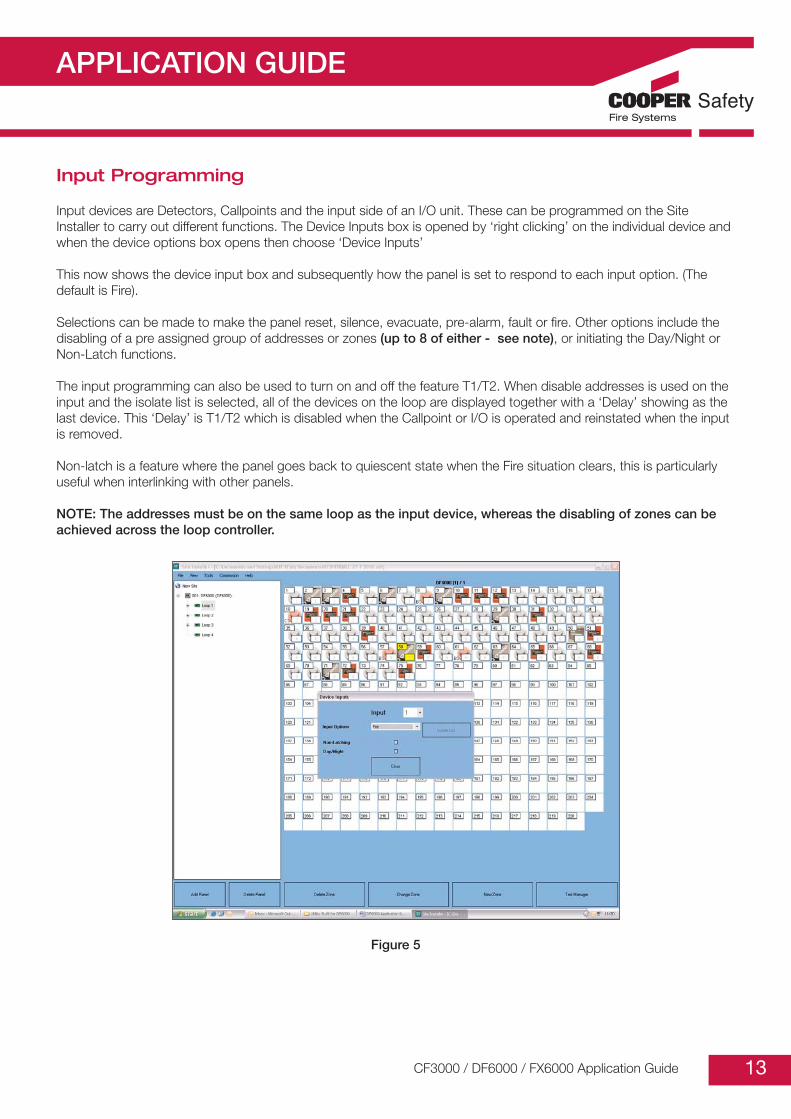
Input Programming
Input devices are Detectors, Callpoints and the input side of an I/O unit. These can be programmed on the SiteInstaller to carry out different functions. The Device Inputs box is opened by ‘right clicking’ on the individual device andwhen the device options box opens then choose ‘Device Inputs’
This now shows the device input box and subsequently how the panel is set to respond to each input option. (Thedefault is Fire).
Selections can be made to make the panel reset, silence, evacuate, pre-alarm, fault or fire. Other options include thedisabling of a pre assigned group of addresses or zones (up to 8 of either - see note), or initiating the Day/Night orNon-Latch functions.
The input programming can also be used to turn on and off the feature T1/T2. When disable addresses is used on theinput and the isolate list is selected, all of the devices on the loop are displayed together with a ‘Delay’ showing as thelast device. This ‘Delay’ is T1/T2 which is disabled when the Callpoint or I/O is operated and reinstated when the inputis removed.
Non-latch is a feature where the panel goes back to quiescent state when the Fire situation clears, this is particularlyuseful when interlinking with other panels.
NOTE: The addresses must be on the same loop as the input device, whereas the disabling of zones can beachieved across the loop controller.
Figure 5
CF3000 / DF6000 / FX6000 Application Guide

APPLICATION GUIDE
14
Output Programming
Outputs are classed as Sounders/Beacons, I/O units, Sounder Control units and Shop Unit Monitors. The panel iscapable of accepting 120 outputs per loop, (60 Sounders set low) and 20 I/O units (each I/O automatically takes threechannels). Sounder Control and Shop units use sounder channels.
To set the device outputs right click the device, when the device options box appears choose ‘Device Outputs’.The output device can now be programmed to respond to a specific trigger – globally, by zone by address or by panel.
Each output can have three stages programmed – whatever is set in each stage that matches the input trigger theoutput will follow (there is no designated hierarchy). However, if the trigger is ‘Global’ in any stage this will always take precedence unless double knock is also set.
If the sounder programming is to be the same for every device then hit ‘apply these settings to other devices’ all of thesounders on the panel will be listed and ‘apply to all’ or apply to selected’ can be hit.
If the sounder trigger is by address, zone or panel then ‘allocate devices box can be used, the allocate devices boxappears and the trigger source can then be selected.
For example if this sounder is to operate only on a specific zone then that zone can be highlighted and moved to theright hand box (up to a max of 16 per stage) and hit ‘ok’.
If there are more than 16 zones that need to be programmed to control an output, then the other 2 stages can beused to increase the allocated zones.
For example: Stage 1 can have zone 1-16, stage 2 can have zones 17-32 and stage 3 can have zones 33-48.
The sounder will now only operate when a device in the selected zone goes into fire
Another feature within the output programming is ‘Any zone 2 devices’ when this is selected and the allocate devicestab hit any zone can be placed in the right hand section. This will effectively double knock the selected zone whereasthat zone must have 2 devices in fire to initiate outputs.
NOTE: Only 1 zone can be placed in the allocation list.
CF3000 / DF6000 / FX6000 Application Guide

APPLICATION GUIDE
15CF3000 / DF6000 / FX6000 Application Guide
Figure 6
Figure 7

APPLICATION GUIDE
16
Add/Delete
This function allows new devices/zones to be added to the system.
When a zone is added then the panel uses the next zone number and adds it to the zone list.
When a new device is added then the panel asks which loop the device is connected to and the scans the looplooking for a reply of 254, once this reply is received that device is allocated the next available address location, thisprocess is then repeated for the next device to be added. It is not possible to add more than one device at a time asmultiple replies of 254 would be received at the same time and the panel would try to address them all with the samelocation number.
Once a device has been added then it will be placed in zone 1, it then needs to be assigned to the correct zone andhave text inserted. Sounders and I/O units can be added but on the older software will not operate so these needed tobe programmed by site installer. Version 2.4.25 addresses the sounder issue but I/O’s are yet to be resolved. (Thepanel must receive a Watchdog reset for this to work)
When zones/devices are deleted then a list of available zones/devices is displayed and the one to be deleted isselected and then the panel removes that zone/device.
When a Zone is deleted all devices in that zone are also deleted (a warning is displayed on the panel to this effect). If adevice is deleted the panel returns the address number back to 254 enabling the device to be re-used
Delete/Add Device cannot be used on address 1 of loop 1, the panel must ALWAYS have a device at this point.
Configure Heat Detectors
When a heat detector has been auto learnt on to a loop the default setting is rate of rise.
If a fixed temperature setting is required then the detector must be changed via the panel menu before the database isdownloaded from the laptop computer otherwise when a check config is carried out the there will be conflicts on allthe heats that are set to fixed temperature on the laptop. If this occurs and is left unmodified then the heat detectorswill operate as rate of rise and may produce unwanted alarms
Network programming
When panels are networked together they each take a network address, this address is set up in the engineering partof the menu along with the total number of panels that are connected on the network. Panel 1 is automaticallyconfigured as the master such that if a network fault occurs the master and faulty panel only will display the ‘LonNetwork Error’.
When setting up a network for the first time after the network card is connected, the panel must have a hard reset orpower cycle to enable the panel to search for and recognise that a card is present. For connection details see the‘Networking section on page 20.
On the network all fires, faults pre-alarms etc. are transmitted to all panels. All user actions such as silence, reset andmute buzzer are also transmitted, so panel 1 could silence the alarms on all other connected panels.
CF3000 / DF6000 / FX6000 Application Guide

APPLICATION GUIDE
17
It is possible to individually configure the panels not to receive silence, evacuate and reset operations from the network;this is particularly useful where the panels are installed in separate buildings such as Student accommodation.
If the network is such that all messaging needs to be turned off but certain panels need to communicate directly witheach other then this can be controlled using the network filtering system where individual panel messaging can beenabled/disabled across the network.
These features are found in ‘Network’ in the configuration menu.
Figure 8 Figure 9
Day / Night Settings
This is a function in the panel programming that allows certain devices to change their characteristics dependant onthe time of day. The devices that respond to this programming are the Heat detectors and Photo thermal.
To program day night mode on the panel you add an input device and then on the input programming menu you tickthe day night box.Then you go to either thermal or photo thermal detectors and on the input programming menu, you tick day nightmode.When you tick day / night on an input unit you are controlling when the panel goes into and out of day / night mode.When you tick day / night on a detector you are instructing that specific detector to respond to day / nightprogramming.
NOTES
1. The input unit in question must be either an I/O unit or a Callpoint.
2. If a 3 Chan I/O unit is used only channel 1 can be used for this function (the other channels will put the panel to full fire.
3. The input unit must be on the same Loop Controller as the devices it is setting to Day/Night
4. As soon as a Photo thermal has a tick against Day/Night the detector becomes pure heat. Hence the Callpoint or I/O must be operated to return this device to dual mode.
5. A half moon indication now appears on the screen between the supervisor button an the clock when day night is in operation.
CF3000 / DF6000 / FX6000 Application Guide

APPLICATION GUIDE
18
High Level Menu
1. Disable all Outputs
This menu enables the engineer to carry out a full test without any outputs operating. This function can not be used with Weekly or Walk test features.
The outputs can be switched on and off from this menu, if however the outputs are inadvertently left disabled when the engineer leaves site, the user can re-enable the outputs from the enable/disable menu in 2214.
2. Buzzer Disabled/Enabled
The Buzzer can permanently disabled using this feature, a disabled led will be displayed on the panel and when interrogating the disable devices in the user menu, this will be shown as 1 I/O disabled.
3. Intermittent Fault Search
When a device goes into fault the panel has polled the detector a number of times to confirm the fault (this is called integration), this can take up to 90 secs dependant on the length of the loop and number of devices installed.
This feature forces the panel to indicate a fault on the first poll, which means the fault will appear almost immediately.
This is particularly useful if a detector has an intermittent fault that would normally not be seen during the standard polling sequence.
Generally this setting should be initiated at the commissioning stage.
4. Logos
This menu allows the engineer to change the Logo shown on the front screen of the panel
5. Reset to Factory Settings
This feature will restore the panel to it’s factory settings, which on a programmed system is catastrophic and not to be used lightly.
The panel will go into Autolearn – losing all programming. It will also re-calibrate the screen and put the default logo onto the screen.
6. Fire Routing & Protection Equip’t
This menu enables delays to be set on these two outputs.
7. Sounder 1 & Sounder 2
This menu allows the conventional sounder circuits to be set to continuous or pulsing, delayed or double knock
CF3000 / DF6000 / FX6000 Application Guide

APPLICATION GUIDE
19
8. Terminology
When the panel goes into Fire the word FIRE or ALARM can be selected to display this as part of the indication on the screen.
9. Autolearn Locking
This fearure has been added to prevent malicious or untrained personnel initiating an Autolearn once the system has been commissioned.
10. Evacuate Locking
Evacuate, once initiated from the panel menu or a programmed input, will operate ALL internal and external outputs connected to the loop. If the panel is controlling critical systems requiring a double knock scenario such as a Gas release system this will be immediately overridden by the evacuate command.
In these instances evacuate would be considered inappropriate, therefore, evacuate can now be locked to prevent it overriding critical programming.
11. Australian FB Screen
This enables the screen to show Zone or Address text when in Australian mode (see page 11)
12. UL 864 9th Edition
This is an additional feature to enable the panel to be operated in areas where UL is specified.Essentially the panel remains the same; however, there are a number of differences in terminology and minor changes to internal software.
Disablements are now displayed as Supervisory warnings, Faults become Troubles.Sounder circuits become Notification appliance circuits (NACS) and the Loops, Signal line circuits (SLC)
The Mute buzzer is acknowledge alarm and as a UL requirement, the buzzer also re-starts after 8 hours if the panel is not reset.
The Callpoint is now a Pull Station.
Earth trouble (fault) now has a separate led indication as well as information on the touch screen and buzzer sounding.
T1/T2 remains the same feature but is now called ‘Positive alarm sequence’.
Alarm Verification has been slightly enhanced to provide 3 time scales 15, 30 and 60 secs
CF3000 / DF6000 / FX6000 Application Guide

APPLICATION GUIDE
20
Networking
1. Introduction
• Up to 64 Easicheck and 127 CF3000 / DF6000 / FX6000 panels can be networked together.• Each panel must have a Self Addressing Network Card fitted to the main PCB. • Network Technology used is “LonWorks” (Protocol).
Figure 10
The network can be wired as either a Loop or a Radial. If Booster devices are used the system must be run as a Radial The maximum cable length before Boosters are used is 1000m. The Terminator resistors are fitted across the network to smooth out the signal. The network requires 51ohms across pos & neg, this can be achieved by cutting off or soldering on resistors as required. (See Figures 10,11,12 & 13)
NOTE: Connection details on the terminal block are not polarity sensitive.
2. Cable Types
The recommended cable for the network connection between panels is an enhanced Firetuf cable manufactured by Draka Cables (Pt No 910234). Screen continuity must be maintained throughout the entire network circuit including each junction point.
The screen should only be earthed at the connection point at the first panel and not at any other point. The screen or drain wire of the network cable should not be considered as a safety earth and therefore should not be connected to the terminals marked with the earth symbol, except at the panel, and should not be insulated with green/yellow sleeving.
Where the network passes between buildings, screen continuity should not be maintained from building to building. A Booster device must however be used irrespective of cable length and should be fitted at a suitable point in the link between buildings. The screen should be connected to the earth of one panel in each building.
The L-Switch Booster is made by a firm called Loytec, and works on a supply voltage of 9-35 v DC. This means that the Easicheck or CF3000 / DF6000 / FX6000 panel external 24v output can power this device. The Booster has twomodes of operation ‘Smart Switch mode’ and ‘Configured Router’, for all applications we use the former mode. In thismode the device automatically detects the bit-rates of the connected channel, copies the information detected on the network and forwards it to the next network card.
CF3000 / DF6000 / FX6000 Application Guide
+ - + -
Terminator resistors = 2 x51 ohms connected in series
Easicheck - E
C 151 B
Network Card

APPLICATION GUIDE
21
3. Configurations
Network configuration without Boosters - Radial
Figure 11
Lonworks Network Configuration – With Boosters
Figure 12
Network configuration without Boosters - With out Boosters
Figure 13
In certain European countries the network needs to have a back-up system should the network fail, in this instance a Dual redundant network card is provided. Essentially this device enables the connection of a second network on a card running in parallel with the existing network. This system is configured in the same way as the normal network.
CF3000 / DF6000 / FX6000 Application Guide
Max. 1000m
Network cardNetwork cardNetwork cardNetwork card
102Ω Terminator
102Ω Terminator
Terminator fittedon network loop
Terminator fittedon network loop
Remove terminatornetwor card
Network card
Booster
Network cardNetwork cardNetwork cardNetwork card
Max. 1,000m102Ω Terminator
Max. 1,000m102Ω Terminator
102Ω Terminator
102Ω Terminator
Terminator fittedon network loop
Terminator fittedon network loop
Remove terminatornetwor card
Network card
Network card
Network card
Network card
Network card
Remove terminatornetwork card
51Ω
Max. 500mTerminator fittedon network card

APPLICATION GUIDE
22
Ancillary Devices
1. Detection
Standard devices include Photoelectric, Ionisation (which will be obsolete by Dec 2007), Multimode heat and the replacement for the Ion, the OptoThermal.
The heat detector defaults to RoR when the panel is in Auto learn, these must be set to the required value RoR, BS (fixed 60 deg) or CS (fixed 78 deg) before upload or download to the laptop.
The OptoThermal has both an optical smoke chamber and a heat element that work in tandem such that the smoke half becomes more sensitive when heat is also present.
Each element will also work independently such that the heat is fixed temp 60 deg and the optical has slightly reduced sensitivity (but remains within the tolerances laid down by EN54).
The OptoThermal and heat detectors are capable of responding to Day/Night programming described on page 16
2. Callpoints
Callpoints are supplied as Surface, Flush mounted and IP 67 Weatherproof. Various accessories can be fitted such as the hinged protective cover, recessing bezel and resettable plastic element.
Generally the inputs of this device are used primarily for Fire, but the Input programming in Site Installer gives the options of setting them to fire, fault, reset, silence, pre-alarm and evacuate.
A call point can also be used to initiate day night mode, isolate addresses or zones or be set to non-latching.
3. Sounders
Sounders, beacons, sounder beacons all appear on the CF3000 / DF6000 / FX6000 device list as alarm/beacons anda maximum of 60 are allowed per loop, the panel and site installer treats them all the same for programming purposes.
The site installer allows 3 stages for the device outputs and various options can be chosen at each stage. Delays can ONLY be used on stage 1. (There is NO hierarchy on the stages whichever setting fulfils the requirement the sounder/beacon will comply with that setting) The settings i.e. sound or volume for the sounders can be done globally at the panel or individually on site installer.
CF3000 / DF6000 / FX6000 Application Guide

APPLICATION GUIDE
23
4. Input/Output Devices
MIO1240is a single input single output device. The output takes the form of a mains rated relay capable of switching up to 8A. The Input spur is used to monitor a set of volt free contacts the end of line being 22k and a firing resistance of 5k6. Programming of the output has the same features as the sounder outputs. The Input programming is the same as programming for the call point.
MIO324is a 3 channel I/O (3 separate inputs & 3 separate outputs) that only takes 1 address. The outputs are three relays capable of switching 1A at 30v. The 3 input spurs have the same function as the MIO1240, 22k end of line, 5k6 firing resistor. Each channel is individually programmable both for inputs and outputs in the same way as the MIO1240. Because this device only holds 1 address there is no way to apply text to the individual channels. This unit contains the same restrictions concerning delays – which can ONLY be programmed on stage 1 of output 1
MIO324TThis unit is identical in build to the MIO 324 but this has been designed to take 3 addresses (this can be expensive in terms of outputs because it replies as 3 x 3Chan I/O’s), this means that text information can be allocated to each channel. It also allows each individual input and output to be disabled (by address).
MIO324SOnce again this unit is identical with the MIO 324 only taking 1 address. The programming is the same as the MIO 324. This unit was designed so that the relay outputs reset on silence rather than full reset, thus enabling the user to interface this device with other fire panels and hence prevents locking up.
MCOMThis unit is a Mini output unit providing switch contacts only, rated at 1A 30v. There is no input on this unit. This item replies as an I/O unit so takes 1 of the 20 I/O’s allowed per loop.
MCOM/SIdentical to the above but this unit is programmed to reply as a sounder, the relay contacts, however, change state on reset not silence. This is done to enable more than the 20 relay outputs per loop by sacrificing the total amount of sounders allowed. NOTE: This unit must be programmed using site installer - the contacts DO NOT change state in Autolearn
MCIMThis unit is a Mini input unit capable of monitoring volt-free contacts in other fire panels, sprinkler flow switches etc. It replies as a I/O unit and therefore will take 1 of the 20 allowed per loop. End of line resistance is 22K the firing resistor being 5K6.
MCIM/CIdentical to the above this unit replies as a Callpoint so therefore the panel can, theoretically, accommodate 150 per loop. The response time of operation has also been modified to operate in the same way as a Callpoint, so this item will put a fire on the panel much faster than a standard input generated from other I/O units.
MCIM/NFThis device is a Non-Fire input and is identical to the MCIM and MCIM/C. This has been programmed not to indicate aFIRE condition on the panel when in alarm. This allows certain outputs to be programmed to respond to this device without the need to create a fire condition on the panel
CF3000 / DF6000 / FX6000 Application Guide

APPLICATION GUIDE
24
5. Zone Monitoring Units
MIU 871This is a true Zone monitor with 2 inputs, one for a zone of conventional call points the second for a zone of conventional detectors (max 20). End of line for the call point zone is 6K8, end of line for the detection zone is the EOLM 1 (the JSB FXN 520 series can only be used on this zone).
MIU 871/ISSimilar to the above but the detection zone has been programmed to accept a Zener barrier and zone of intrinsically safe detectors. End of line for this zone now becomes 6K8 and the diode in the detector base must be removed.
MIU 871CUKThis device has been programmed as a Technical input similar in effect to the Non fire input. This device can be used in conjunction with a Fan controller, and can be used to provide confirmation of operation (feedback) from an extract fan or smoke vent.
MSU 840Another zone monitor similar to the MIU 871, this unit also has a fire relay rated at 30v 1A and 2 conventional sounder circuits fully monitored. The power supply, which is also monitored, is the FX1A and must be fitted even if the sounders are not used.
MSU 840CThis device provides the output to control an extract fan or smoke vent in conjunction with a Fan control unit.
6. Fan Controller FC6
The FC6 Fan Controller is designed to satisfy the requirements of Australian standard AS1668 & can be connected to a Cooper analogue addressable fire alarm control panel by means of the comms Loop utilizing only one address.
There are 6 channels per Fan Controller capable of controlling & indicating 6 individual Fans.
Each channel is programmed to an output device and feedback input device in the loop (for example, MSU 840-C, MIU871cUK modules) to control & monitor the status of the Fan. A new module has been created which provides 2 addresses the first to control the feedback the second to provide output and reset controls for the fan
In Automatic mode the Fan is controlled by the CF3000 / DF6000 / FX6000 in the normal way through the site installerprogram. Feedback must be detected from the Technical input within 25 secs or a fault will appear on the FC6
In manual mode the Fan can be started and stopped using the Start/Stop buttons on the FC6, again once the start button has been operated then feedback must be received within 25 secs.
7. 4 Way Sounder Control Unit (MPU 424)
The MPU 424 is designed to accept 4 conventional sounder circuits with a total rating of 3.2A spread equally over the 4 outputs. This unit takes 1 address on the DF6 system and has its own power supply and battery backup. Each individual circuit can have the same programming as a single loop sounder output.
The only criteria being that a delay can ONLY be put on stage 1 of channel 1.
CF3000 / DF6000 / FX6000 Application Guide

APPLICATION GUIDE
25
8. MARDF6
Because the loop output devices cannot be programmed for fault, the MARDF6 was designed to provide a fault relay with dry contacts for use with an Autodialler or Redcare that requires a fire and fault signal. This unit connects across the FRE or FPE outputs and the Fault output. The internal 24v supply in the panel powers the unit.
9. Spur Isolator- MSI850
This unit is designed to accommodate a Spur of addressable devices but does not take an address itself. If the unit is installed at the outset the panel autolearns up to this device autolearns the spur and then carries on with the remainder of the loop. The spur isolator can also be added after the panel has been autolearned but any devices on the spur MUST be added ONE AT A TIME.
If all devices are run off a number of Spur isolators, then one single device MUST be fitted on the loop between the last isolator and the return run to the panel. (If this is not done then ‘Short circuit far’ will be displayed on the panel)
10. Beam Detector MAB50/100R
The reflective beam detector uses one address on the system. Initially the unit is autolearned and then aligned using the Dill switches on the rear of the unit. The 3-position switch is set to position 1 ‘Prism target Mode’ align to the prism using the thumbscrews. Once the prism has been correctly targeted the prism MUST be covered to ensure the device is not receiving reflections from other sources. Set the switch to position 2 ‘Alignment Mode’ and fine-tune the alignment using the thumbscrews. Finally, once fully aligned, set the switch to position 3 ‘Run Mode’.
11. Repeaters
Repeater panels can either be Loop connected taking one address in the number sequence, or connected via the network, in which case the repeater will be fitted with a Network card.
The loop repeater has functionality limited to sound/silence alarms or reset the system. The internal buzzer can now be muted from the main or a networked panel (added Aug 2010)
The supervisor access code (2214) can be disabled or changed using the engineer menu (2132).
The Loop repeater must have the same text downloaded into it as the main panel it is connected to. This is achieved by connecting the laptop to the repeater using the same download cable as the main panel, using the engineer code to ‘Download CF3000 / DF6000 / FX6000 text’.
This text information is stored in the Display pcb, whereas the device address is stored in the Psu board.The Touch screen repeater is ONLY networkable but allows the user much more control such as disabling devices across the network. This panel also has a programmable input and Fire and Fault relays.
CF3000 / DF6000 / FX6000 Application Guide

APPLICATION GUIDE
26
Getting Started & Fault Diagnosis
Powering the panel
When the panel is powered up it will go through a boot up sequence and will test all the display LEDs. The touchscreen should be illuminated and show the normal front screen. If that does not happen this section details commonproblems and methods of fixing the problem.
Panel takes a long time to start the boot up sequence after a watchdog reset (or power up).
On 4 loop panels (with 2 loop driver cards) there may sometimes be a long delay in watchdog. The following steps willspeed up a reset:1. Place a jumper link on a loop driver (2 pins near crystal).2. The panel will reset and the relay click will be heard 4-6 seconds later.3. Remove the jumper link from the loop driver card.
IMPORTANT the jumper link must not be left on a panel once it is booted up.
Power LED not illuminated
If this happens, the display PCB is not getting power. The following steps should help identify where the fault is. Always power down the panel before disconnecting and connecting any PCB wires or cables.
Refer to CF3000 / DF6000 / FX6000 Motherboard drawing
First confirm the PSU PCB is working correctly. Disconnect the red multiway connector from the PSU and motherboard, check it’s continuity. Check the voltage on the battery connectors, this should be around 26V. If this is lowercheck the battery fuse – replace as necessary. If the fuse is OK, then the PSU PCB needs replacing. Power up the PSU and carefully check the +26V and +26Vraw connectors are at around 26V, if they are power downthe PSU and reconnect the PSU to the motherboard by the red connector.
Next confirm the motherboard is working. Disconnect the ribbon cable, loops etc. only leave the connection to thePSU. Find the test points on the Loop motherboard PCB check +26V, +26Vraw and also Vcc (should be 5V). If any arelow check the PCB for any contamination shorting on the board. If this doesn't clear the problem replace themotherboard. Next connect the display ribbon cable only. Check the Vcc on the motherboard and the display board. Ifit is 5V on the motherboard only replace the ribbon cable. If both are low check the display for shorts. Replace themicro board and display board separately to locate which is faulty.
Power LED on but touch screen is not illuminated
Connect a PC using panel comm. When the panel is reset debug code should be shown on panel comm, if it is thefollowing should fix the problem:1. Ensure the connector on the inverter is securely in position.2. Ensure the micro board is securely connected to the display board.3. There are two 5V regulators on the motherboard, check both Vcc and 5V backlight are at 5V, if not replace the
motherboard, if they are replace the display board. 4. If the panel does not respond on panel comm, ensure the micro board is connected to the display PCB securely.
Otherwise replace the micro and display PCBs.
CF3000 / DF6000 / FX6000 Application Guide

APPLICATION GUIDE
27
Power LED and touch screen illuminated but no text visible
When the panel is powered down the touch screen needs a minute to reset. Power the panel down and disconnectthe batteries for 90 seconds, then re power the panel. If this does not work connect panel comm and press the resetbutton. After a few seconds the PC should show debug code scrolling on the panel comm application. If it does notshow debug text, ensure the micro board is securely in place.
If there is still no debug text the micro board or display PCB may need replacing. If debug text is shown on the PC thecontrast may need adjusting on the micro board or either the micro board or the touch screen may need replacing.
Screen is visible but touch screen does not respond to touch
1. Ensure the touch screen connector is in correctly.2. Ensure the micro board is securely attached to the display board.3. Send '7' from a PC to the panel to start the screen calibration routine.
The touch screen works and is correctly calibrated but I cannot get to the supervisor entry screen.
The panel may be in Swedish mode. If this is the case then to get access to the menu system the class change inputneeds to be momentarily shorted.
The access code entry screen will now be accessible.
To disable Swedish mode on the panel, use the engineer level access code, select configure > program I/O’s andsounders > Auxiliary board. Swedish mode will be selected, press not required then exit. The panel will now behavecorrectly.
The general disabled LED is illuminated
If this occurs something is disabled on the panel or a time delay has been programmed on the panel. To clear this usethe 'enable all' button from the enable/disable menu in the supervisor access level.
An alternative method, provided a delay has NOT been programmed then go to the enable disable menu and insteadof enabling all devices, go to enable disable I/O, and then disable the delays.
CF3000 / DF6000 / FX6000 Application Guide

APPLICATION GUIDE
28
Commissioning
Check the loops with a multimeter
Auto-learn the panel
Upload to a PC (Optional)
Download from a PC
Check auto-config
Run Intermittent Fault search
Test the devices
1. Loop Checking with a multimeter
The first quick test that should be done on all the loops is to check the continuity of the loops using a multimeter.
The resistance should be measured start positive to end positive, start negative to end negative, and positive tonegative at the start and end of each loop.
The resistance along the positive line should be less than 50 ohms. The resistance across the negative line should be2k5 ohms for each device on the loop, e.g. 20 devices should measure 50k ohms.
The resistance across the loop positive to negative will be in the Mohm region.
Ensure the screen is continuous around the loop, this reading should be approx 10 ohms. The screen should not be bonded to building earth.
Test the loops with the multimeter set to AC volts – this is to check that there is no induced voltage which could becaused by the cables being run too closely to a high voltage source.
This will show if anything drastic is wrong with the loop devices wired in backwards breaks etc. If there is a short at theend or start of the loop this will need to be fixed before powering the panel.
2. Auto-Learn Function
This is accessed through the engineer level access code. When the panel is auto-learned all the devices addressinformation is set up from address 1 upwards from the start of each loop, previous addressing is lost. Once the panelhas finished the auto-learn it will reset itself. After this is done reset the panel using the touch screen.
CF3000 / DF6000 / FX6000 Application Guide

APPLICATION GUIDE
29
Faults and Solutions
The panel should now display system healthy, the following are common faults and solutions:-
1. Dual address
The panel shows this fault if two or more addresses are responding at the same time. The most likely causes wouldbe:-
Device wired incorrectly. See wiring diagram for the device
Base switch not opening. The switch on the base can occasionally be pushed above the metal tab preventing theswitch from opening. See diagrams below.
Correct Incorrect
Figure 14
If this is the case the switch may need to be clicked under the tab, if this fails the base may need replacing.
Detector not correctly inserted on base. If a detector is not fully inserted onto a base it is possible that the base switchwill not be opened. The newer detectors and bases have a tab to show when the detector is fully inserted. Seediagram below.
Figure 15
CF3000 / DF6000 / FX6000 Application Guide

APPLICATION GUIDE
30
Base sounder device not wired correctly. When a detector is inserted onto a base sounder there is not much roombehind the detector. If the cabling is not cleared from the base, see images below.
Incorrect Correct
Figure 16
The detector may be pushed away from the base preventing the switch opening, or crushing a contact and thus notreceiving power. Spur isolator wired incorrectly. See wiring diagram for spur isolator.
2. Open circuit” Positive/Negative
This means after the auto-learn the panel has detected a break in the positive or negative line. The most likely causeswould be:-
Device wired incorrectly. See wiring diagram.
Base switch opening but the detector not making contact. Ensure the base contacts are correctly screwed down, andnone are damaged. Then ensure the detector is replacedcorrectly.
A negative break may also be caused by a short at a device inthe middle of the loop that the loop device isolators havedetected and dealt with. See short circuit middle below.
If the loop voltage drops (below 18 vDC) the devices may resetcausing an open circuit negative. (There must not be more than2Km of appropriate properly earthed cable used per loop.) If afaulty device is suspected it can be seen by linking the loop in thepanel and disconnecting the far end of the loop, see diagram.
Measuring the voltage across the end of the loop for correctfunction this should be over 15V (usually over 18V). If the panel isleft in this state the end devices will go into fault. The faultydevice should be one of the active devices.
Figure 17CF3000 / DF6000 / FX6000 Application Guide

APPLICATION GUIDE
31
3. Short Circuit” start or end of a loop
There is a short at the start or end of the mentioned loop. The fault can only be on the panel. The first/last device orthe wiring in between the panel and the device. This prevents the loop driver from functioning and must be fixed inorder to auto-learn the panel. Common causes would be:-
Either the first or last device is wired incorrectly.
The loop connections into the panel are wrong.
Something is shorting on the PCB.
No device between the last Spur Isolator and the panel
If the initial loop test didn't show a short across the loop power down the panel and remove the loop driver. Measurethe resistance across the loop using the appropriate terminals, If this is still in the Mohm region change the loop drivercard. If this is short circuit recheck the loop by disconnecting the loop and measuring. If this is Mohms change the motherboard.
4. Short circuit middle
Device wired incorrectly. See wiring diagram. Device is drawing too much current. A faulty device may draw too muchcurrent and be detected as a short. Replace the device.
5. Fault at address
There are several possible causes of faults at individual addresses, the panel may show more information (e.g. whichchannel for 3 channel IO) or may show analogue value for the fault:-
Device is missing, unlikely after an auto-learn as a missing device wouldn't have addressed. Incorrect earthing maycause this. This fault would have an analogue value of 0.
A repeater, sounder control unit have their own power supply if the PSU is not on and there is no battery, the devicewill show a fault, analogue value 0.
Detector low analogue value fault. If the detector shows analogue value of 1 the detector may need replacing orcleaning.
End of line resistors not correct. IO units, ZMUs etc. have end of line resistors. If they are not wired correctly the panelwill show a fault at this address but will give specific information (ZMU detector zone etc.) about the fault.
6. Earth Fault
An earth fault may be associated with other faults or random fires. This should be cleared before trying to cure theother faults as it may be the root cause.
Power down the panel, disconnect all loops, sounders and relay connections. Ensure the panel is correctly earthed.
Check the +ve & -ve cables to screen/earth, ensure greater than 1 Mohm. Check that the screen is not tied to buildingearth. Repower the panel if the fault remains with the cables disconnected, examine the Pcb’s for contaminants orshorts.
CF3000 / DF6000 / FX6000 Application Guide

APPLICATION GUIDE
32
7. Sounder 1 or 2 Fault
This is a fault on one of the two conventional sounder channels. Common causes would be:-
One of the fuses has blown.
End of line resistor not fitted.
Sounder wired incorrectly. See wiring diagram.
Sounder circuit is shorted.
8. FRE, FPE, Fault relay Fault
These are the other panel outputs, faults on these could be:-
End of line resistor not fitted.
Output line is shorted.
9. The panel goes into fire straight after auto-learn
This can be caused by the following:-
Dual addressing, causing the panel to interpret a signal as fire. This will show itself if there is a dual address fault at the same address as the fire (it will take longer for the fault to showthan the fire).
Device triggered into fire, detector reading high analogue value, call point with glass broken or not correctly fitted. Thepanel should show a fire at an address and the LED should be on at that address. Silence the panel, check theaddress that is in fire. When the problem is fixed check the analogue value using the commission screen on theengineer level access.
10. The panel constantly resets after auto-learn
This is a specific dual-addressing fault. Certain combination of devices dual addressing may cause the panel to thinkthey are a repeater and respond to the responses by constantly resetting. The following steps should be done toremove this problem. Remove the loops from the panel, the panel will stop resetting. Go to the delete device menu inthe engineer menu and delete all the repeaters from the panel.Reconnect the loops, the panel will not reset.
Locate the dual addressing devices (see opposite to locate a fault) and fix the problem.
Auto-learn the panel, it should no longer reset, if it does repeat the above and locate any further dual addressingproblem.
CF3000 / DF6000 / FX6000 Application Guide

APPLICATION GUIDE
33
11. The panel fails to auto-learn past a device
This may be seen with short or open circuit on the loop, the problem will probably be located at the last devicedetected or the next one along. See the above on open circuit positive/negative. If there is no associated open circuitthe device may be faulty, link out the device after the last one auto-learned and try again. If this fails link out the lastdevice detected and auto learn again. If either device is causing the problem replace it. Once the faults have beenremoved from the panel and it shows system healthy after a reset go to the system details screen and check thenumbers of devices on each loop is the same as what has been installed on each loop (spur isolators do not show onsystem details). If this number is less than expected the following may be the cause:-
If spur isolators are fitted the spurs may not be correctly installed. To check this do test device on what should be thelast device on each spur (see locating a fault below), if the incorrect device LED is on work back along the spur withtest device until a device is correctly identified. The problem may be that device or the next one along the spur, seeopen circuit negative/positive above.
If no spur isolators are present or the spurs are all working ensure the site devices have all been connected to the loop.
12. Locating a fault on a loop
If the fault is a short circuit middle or a open circuit on the loop the check auto-config function can be used. This is inthe supervisor level on the others section of the display. When this function is used the panel will go round the loopfrom the start until it cannot communicate with a device it will then show an open circuit at an address, this will helplocate a short/open circuit in the middle of a loop. If check auto-config shows a fault at the end of the loop but noshort or open can be found, the problem may be a resetting detector, see 'loop voltage drop' above in “Open circuit”Positive/Negative section above. Alternatively run the Intermittent fault search in the high level menu.
If an address is suspected as been faulty or dual addressed the test device function can be used to locate the device.Test device is in the engineer level under testing. When a device is put into test its LED should light up, two will light upif both devices have the same address. If the tested device is a sounder it will sound continuous. Sometimes the faultydevice will not respond if this is the case test the device before the faulty one and the one after the faulty one to helplocate the exact device.
Other Faults
1. Charger Fault
This will show if the charge current is too low. Possible causes for this are:-The charger fuse has ruptured.The batteries are disconnected.The batteries are damaged.
2. Battery Fault
This will show if the charge voltage is too low. Measure the float voltage at the battery terminals, it should be around26V depending on how charged the batteries are. This could be low if the batteries are damaged, replacing thebatteries should clear the fault.
3. Mains Fault
If this is the only fault on the panel the LCD back light will be off. Touch the top left of the screen to light the screen.The panel will only run on batteries for one or three days depending on it's configuration. When the mains returns thepanel will need resetting to clear this fault. If the fault returns after a reset check the mains input.
CF3000 / DF6000 / FX6000 Application Guide

APPLICATION GUIDE
34
4. Error Codes
The following are a list of error codes that may appear during the boot sequence of the panel.
#define ERR_TEXT_LARGE 0#define ERR_TEXT_SMALL 1#define ERR_LINE_LARGE 2#define ERR_LINE_SMALL 3#define ERR_PIXEL_LARGE 4#define ERR_PIXEL_SMALL 5#define ERR_RECT_LARGE 6#define ERR_RECT_SMALL 7#define ERR_ARROW_SMALL 8#define ERR_ARROW_LARGE 9#define ERR_ARROW_CODE 10#define ERR_TEXT_BUFFER_OVERFLOW 11#define ERR_BITBLT_LARGE 12#define ERR_BITBLT_SMALL 13#define ERR_TEXTOUT_LENGTH 14#define ERR_TEXTOUT_LARGE 15#define ERR_TEXTOUT_SMALL 16#define ERR_LINE_DOT_LARGE 17#define ERR_LINE_DOT_SMALL 18#define ERR_LOG_ADD_FAILED 19#define ERR_SEARCH_NO_HI 20#define ERR_SEARCH_NO_LO 21#define ERR_SEARCH_FIRST_LAST 22#define ERR_SEARCH_0 23#define ERR_SEARCH_COL 24#define ERR_SEARCH_UNKNOWN_DB 25#define ERR_SEARCH_UNKNOWN_CONDITION 26#define ERR_SCREEN_SMALL 27#define ERR_SCREEN_LARGE 28#define ERR_PRESET_LOAD 29#define ERR_PRESET_SAVE 30#define ERR_PANEL_LOW 31#define ERR_PANEL_HIGH 32#define ERR_LOOP_LOW 33#define ERR_LOOP_HIGH 34#define ERR_ADDR_HIGH 35#define ERR_ZONE_HIGH 36#define ERR_LOG_HIGH 37#define ERR_ZONE_LED_SMALL 38#define ERR_ZONE_LED_LARGE 39#define ERR_LOOP_COMMAND 40#define ERR_ADDR_LOW 41#define ERR_UNK_LATCH 42#define ERR_UNK_DEVICE_TYPE 43#define ERR_DEV_ZONE 44#define ERR_DEV_TYPE 45#define ERR_LOOP_DRIVER_HIGH 46#define ERR_NO_LOOPS 47#define MAX_ERROR 48
CF3000 / DF6000 / FX6000 Application Guide

APPLICATION GUIDE
35
Programming Issues
Once Autolearned, the panel will work as a basic fire alarm provided there is no cause and effect required on the site.The panel, however, can transfer this learned information to the Site Installer program on a laptop, where full zone andaddress text can be programmed together with different relay outputs, sounder settings etc. and any Inputprogramming to fulfil any customer requirements.
NOTE: Programming, when completed must be in conjunction with total numbers and settings laid down in theprevious sections of this guide.
Once programmed, this information can then be returned to the panel.
A number of issues have been identified:
1. If the program will not go back into the panel, this is likely to be corrupted or incorrectly set up or the display micro (CDR) is corrupt. Power down the panel and remove the loop driver cards. Power the panel again and carry out an Autolearn (this effectively clears the CDR). Power down again and install the loop driver(s), re-power and try to reload the program. If this will still not download then check the program or replace the micro.
2. If after successful download the panel goes into random fires – this is almost always due to an incorrect program. (or the wrong program for the site).
3. If after successful download, and during testing various sounders do not operate. This could be due to too many zones being programmed for each sounder stage (max allowed is 16).
4. If after successful download, and during testing sounder begin to stop operating. This could be due to the sounders being set to too high a volume and hence taking too much load. Check sounder settings and turn down the volume if necessary. If this is not the case check the hardware Revision number on the reverse of theLoop driver, ECN818 is the latest version that delivers better load performance than the previous(ECN651).
5. If after successful download the panel display no faults, but the front screen says ‘System Healthy 0 Zones Active’, this is associated with a networked system. Following a download the panel address and number of panels in the network can sometimes be returned to 1. Go into the commissioning menu and set up the network address and total number of panels in the network.
CF3000 / DF6000 / FX6000 Application Guide

APPLICATION GUIDE
36
Program Updates
1. Loop Driver
Loop Driver software can be updated using a Cyclone Pro programming device; alternatively to update the softwarethe loop driver will need replacing.
2. Display
The display program can be updated using a utility program called Panel Prog. This can only be carried out in thismanner on the latest software releases (Aug 08).
Alternatively to update earlier versions of software the display micro will need replacing.
The display program can be updated using the Panel Prog program and Hyperlink as follows;
The number one rule is: Never, NEVER, program the wrong code into your panel. If you do, you will probably have tofind some other way to re-program your panel.
1. Connect Laptop to the panel via the serial port.
2. Open HyperTerminal program and apply a name in the new connection box. Click OK
3. Select Com 1 in the ‘connect to’ box. Click OK
4. In the Comm 1 properties box set - 38400 baud, data bits 8, parity none, stop bits 1 and no flow control.
5. Data will now start scrolling down the screen area.
Figure 18
CF3000 / DF6000 / FX6000 Application Guide

APPLICATION GUIDE
37
6. In HyperTerminal, press ctrl-x, and then 'y' immediately. This will erase the current program in the display micro.
7. Wait until the text "WAITING FOR PROGRAM" appears in HyperTerminal window.
8. Close HyperTerminal.
9. Run PanelProg.exe, and ensure the correct serial port is selected. (It normally defaults to comm. 3)
Figure 19
10. Load your .s32 file with the relevant program into PanelProg.exe. by clicking on the ‘open’ tab.
11. Click "update the panel".
12. It may initially give you a timeout error, if so, just click "update the panel" again. The whole process should take about 5 mins, it is important not to interrupt it.
CF3000 / DF6000 / FX6000 Application Guide

APPLICATION GUIDE
38
Panel Comm
Panel Comm is a useful little program that allows engineers to connect directly to the panel via the upload/downloadport.
This program is capable of communicating with the panel by way of sending commands to perform certain functionsor receiving information also on command.
Once opened the program needs no configuration and information will be seen to be scrolling in the main displaywindow, such as ‘Updating time on screen’ or ‘Lon data request’ if the panel is networked.
Figure 20
Commands can be sent to the panel by putting a code into the line adjacent to the ‘Send’ button and hitting ‘Send’.
The list of commands are:
Code Function Code Function1 English CF3000 / DF6000 / FX6000 2 Test Screen3 Touch Screen Test 4 LED Test5 (Spare) 6 List CDR7 Calibrate Screen 8 Screen Dump9 Watchdog Reset A Reverse videoB French C Font testD Animation E Simulate FireF Backlight on/off G Printer TestH Printer Status I LON TestJ Debug mode on/off K Full ChecksumL Shutdown/Activate M Erase CDRN Simulate Fault O Simulate Pre-alarmQ FRE Test R Rabbit TestS Sounder 1 T (Spare)
CF3000 / DF6000 / FX6000 Application Guide

APPLICATION GUIDE
39
Download Analogue levels and Log to PC
A recent update to the display software (v 3.3.1 or later - Jan 2009) allows the engineer to download the Analoguelevels and history log to a PC using the HyperTerminal program.
This new feature is housed in the user menu. Proceed as follows to download the information to the Laptop:
1. Connect Laptop to the panel via the serial port.
2. Open HyperTerminal program and apply a name in the new connection box. Click OK
3. Select Com 1 in the ‘connect to’ box. Click OK
4. In the Comm 1 properties box set - 38400 baud, data bits 8, parity none, stop bits 1 and no flow control. Data will now start scrolling down the screen area.
5. Select ‘Transfer’ and from the drop down box choose ‘Receive file’
6. In the ‘Receive file’ box use the ‘Browse’ button to select where the file is to be saved
7. In ‘Use receiving protocol’ choose ‘Xmodem’ then hit ‘receive’.
8. When the ‘receive filename’ box appears give the file a name and click ‘OK’
9. Go to the panel and select ‘Send analogue value or Log to PC, choose a loop to be transmitted hit ‘OK’
10. Another box will appear showing the status of the download.
11. Once the file has been downloaded then this can be accessed for reading or printing by ‘right click’ on the file and ‘Open with’ Microsoft Word.
CF3000 / DF6000 / FX6000 Application Guide
Figure 21 Figure 22

CF3000 / DF6000 / FX6000 MOTHERBOARD
40 CF3000 / DF6000 / FX6000 Application Guide
Test
Test
CF3
000
/ D
F600
0 /
FX60
00 M
othe
rboa
rd (.
ypcb
2153
)+ ++ ++
+++
++
++++
++
++
++
++
++
++
++
+++
++
++
++++
+++
Au
x
Rel
ay
Fau
lt
Rel
ay
24
v
0/p
Fire
P/E
Fire
R/E
Loo
p 1
Loo
p 2
L
oo
p 3
Lo
op
4C
lass
CX
So
un
der
1&
2
S
ou
nd
er 3
& 4
Co
nn
ecto
r to
PS
U
.
.
Test
Test
Test
Test
Test
Volta
ges
mea
sure
d at
mai
n co
ntac
ts w
ith m
ains
and
bat
tery
con
nect
ed.
>
Aux
Rel
ay :
Dry
con
tact
s N
O/C
/NC
>
Faul
t Rel
ay O
utpu
t : 1
3.6v
no
faul
t 0v
whe
n in
faul
t>
28
v O
utpu
t : 2
8.5v
app
rox
with
no
load
>
Fire
P/E
& R
/E :
-0.6
v no
fire
+28
v w
hen
in fi
re>
Lo
ops
1-4
: 0v
unus
ed, +
22v
norm
al, +
24v
in fi
re>
S
ound
er 1
-4 :
-0.6
v m
onito
r, +
28v
whe
n in
fire
.
Volta
ges
mea
sure
d at
ver
tical
red
conn
ecto
r w
ith m
ains
and
bat
tery
con
nect
ed.
>
+26
v to
0v
: rea
ds a
ppro
x +
27.8
v>
+
26v
Raw
to 0
v : r
eads
app
rox
+28
.15v
>
+5v
Prin
ter
to 0
v : r
eads
app
rox
+5.
5v
Volta
ges
mea
sure
d ac
ross
bat
tery
lead
s us
ing
6K re
sist
or a
s lo
ad, m
ains
con
nect
ed.
>
Fact
ory
set t
o gi
ve +
27.5
v
+ 2
6v
0v
+ 2
6v R
aw
0v
+ 5
v
Prin
ter

NOTES
41CF3000 / DF6000 / FX6000 Application Guide

CC1806
Head Office
SalesTel: 01302 303999Fax: 01302 303333Email: [email protected]
TechnicalTel: 01302 303350Fax: 01302 303332Email: [email protected]
ExportTel: 01302 303334Fax: 01302 303345Email: [email protected]
SreviceTel: 01302 303352Fax: 01302 303332Email: [email protected]
Web: www.cooperfire.com
Head Office
Cooper Lighting and Safety LtdWheatley Hall RoadDoncasterSouth YorkshireDN2 4NB
Cooper Industries Plc600 Travis, Suite. 5800Houston, TX 77002-1001P: 713-209-8400www.cooperindustries.com