cc1310 skyworks 433mhz pa reference design - ti.com · important notice for ti design information...
TRANSCRIPT
1SWRA528–May 2017Submit Documentation Feedback
Copyright © 2017, Texas Instruments Incorporated
CC1310 Skyworks 433MHz PA Reference Design
Application ReportSWRA528–May 2017
CC1310 Skyworks 433MHz PA Reference Design
Albin Zhang and Richard Wallace
ABSTRACTThe frequency range 426 MHz - 435 MHz is designated for ISM applications in several countries. Thisfrequency range is commonly known as the 433 MHz band. Each country has their specific frequencyband range and the China ISM band defined by SRRC is 430 MHz - 432 MHz and 433.00 MHz - 434.79MHz.
CC1310 reference design [8] operates from 420 MHz to 510 MHz with 15 dBm output power. If higheroutput power is required in the 433 MHz band, TI provides a reference design [3] with Skyworks Solutions.The combination of CC1310 wireless MCU [2] and SKY66115-11 FEM [4], addresses customers’ needsfor easy-to-use, long-range, low-power and low-cost solutions serving applications across the Internet ofThings (IoT). The reference design covered in this application report can support up to +20 dBm TX powerwith high power efficiency at 433 MHz.
Contents1 Introduction ................................................................................................................... 22 Design ......................................................................................................................... 23 Measurement Results ....................................................................................................... 84 Summary .................................................................................................................... 115 References .................................................................................................................. 11
List of Figures
1 CC1310EM-SKY66115-4051 Board....................................................................................... 22 CC1310 Block Diagram ..................................................................................................... 33 Schematic - CC1310EM-SKY66115-4051 Rev2_0_x .................................................................. 44 CC1310EM-SKY66115-4051 Layout...................................................................................... 55 DIO Configuration in SmartRF Studio 7 .................................................................................. 66 Tx Mode Configuration...................................................................................................... 77 Rx mode configuration ...................................................................................................... 88 Matching of the Antenna With ANT1 and ANT2 Components ....................................................... 109 Antenna Bandwidth at VSWR: 2 ......................................................................................... 10
List of Tables
1 SKY66115-11 Truth Table.................................................................................................. 62 Conducted Output Power and Harmonics, 3.3 V ........................................................................ 83 TX Output Power, Current Consumption vs. Power Table, 3.3 V ..................................................... 9
TrademarksSmartRF is a trademark of Texas Instruments.Cortex is a registered trademark of ARM Limited.
Introduction www.ti.com
2 SWRA528–May 2017Submit Documentation Feedback
Copyright © 2017, Texas Instruments Incorporated
CC1310 Skyworks 433MHz PA Reference Design
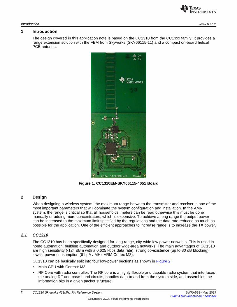
1 IntroductionThe design covered in this application note is based on the CC1310 from the CC13xx family. It provides arange extension solution with the FEM from Skyworks (SKY66115-11) and a compact on-board helicalPCB antenna.
Figure 1. CC1310EM-SKY66115-4051 Board
2 DesignWhen designing a wireless system, the maximum range between the transmitter and receiver is one of themost important parameters that will dominate the system configuration and installation. In the AMRsystem, the range is critical so that all households’ meters can be read otherwise this must be donemanually or adding more concentrators, which is expensive. To achieve a long range the output powercan be increased to the maximum limit specified by the regulations and the data rate reduced as much aspossible for the application. One of the efficient approaches to increase range is to increase the TX power.
2.1 CC1310The CC1310 has been specifically designed for long range, city-wide low power networks. This is used inhome automation, building automation and outdoor wide-area networks. The main advantages of CC1310are high sensitivity (-124 dBm with a 0.625 kbps data rate), strong co-existence (up to 80 dB blocking),lowest power consumption (61 µA / MHz ARM Cortex M3).
CC1310 can be basically split into four low-power sections as shown in Figure 2:• Main CPU with Cortex®-M3• RF Core with radio controller. The RF core is a highly flexible and capable radio system that interfaces
the analog RF and base-band circuits, handles data to and from the system side, and assembles theinformation bits in a given packet structure.

www.ti.com Design
3SWRA528–May 2017Submit Documentation Feedback
Copyright © 2017, Texas Instruments Incorporated
CC1310 Skyworks 433MHz PA Reference Design
• General Peripherals• Sensor Controller
For more in-depth information on the CC1310, see the CC1310 SimpleLink™ Ultra-Low-Power Sub-1 GHzWireless MCU Data Sheet (SWRS181).
Figure 2. CC1310 Block Diagram
2.2 SchematicThe RF core of CC1310 is highly configurable and the radio front-end can be set to differential or singleended. With a differential output configuration, the maximum output is 14 dBm. With a single endedoutput, the maximum output is 11 dBm. Several customers have requested an output power up to 20dBm,the CC1310 transmitter was configured as a single ended port (RF_P set to Tx) connected to an externalFEM with an integrated amplifier, see Figure 3. If an output power of 14 dBm is sufficient then thestandard reference design for 420 MHz to 510 MHz can be used [8].
The schematic shown in Figure 3 is a general schematic (Rev 2.0.x) to cover the ISM frequency bandsfrom 400 MHz to 510 MHz; the BOM is specified for three different ISM frequency bands:• 470 MHz – 510 MHz: BOM - CC1310EM-SKY66115-4051 Rev 2.0.1• 420 MHz – 440 MHz: BOM - CC1310EM-SKY66115-4051 Rev 2.0.2• 400 MHz – 420 MHz: BOM - CC1310EM-SKY66115-4051 Rev 2.0.3
Design www.ti.com
4 SWRA528–May 2017Submit Documentation Feedback
Copyright © 2017, Texas Instruments Incorporated
CC1310 Skyworks 433MHz PA Reference Design
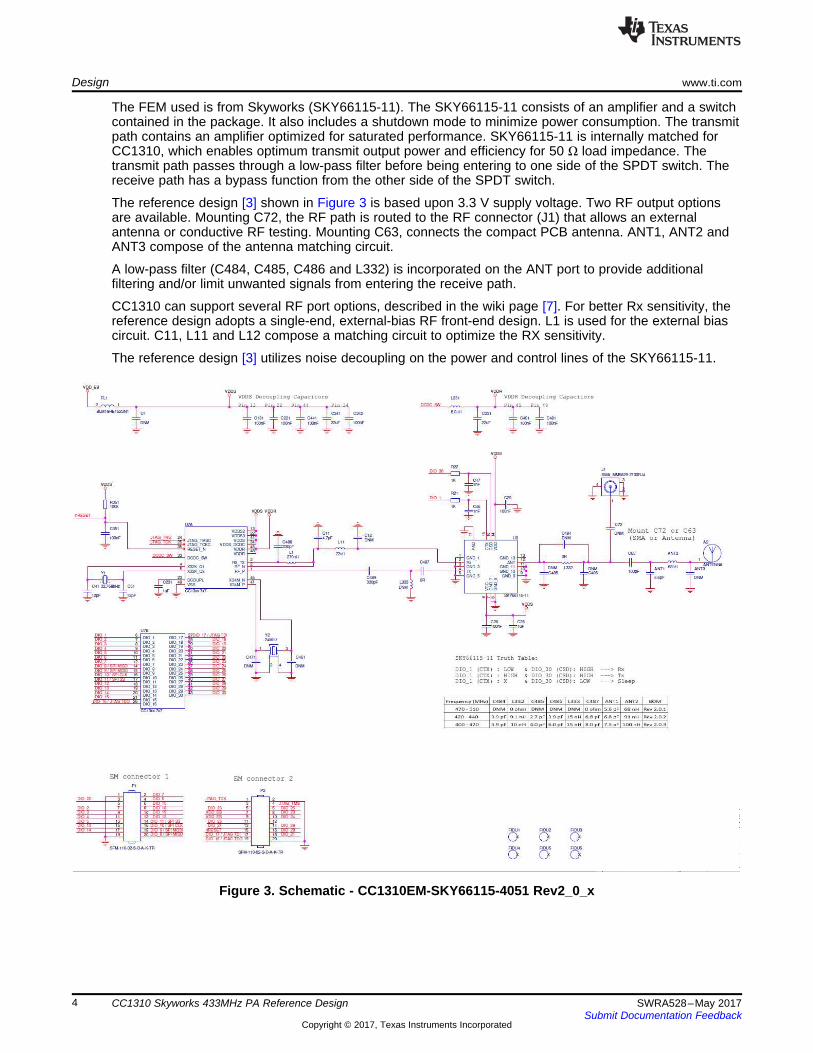
The FEM used is from Skyworks (SKY66115-11). The SKY66115-11 consists of an amplifier and a switchcontained in the package. It also includes a shutdown mode to minimize power consumption. The transmitpath contains an amplifier optimized for saturated performance. SKY66115-11 is internally matched forCC1310, which enables optimum transmit output power and efficiency for 50 Ω load impedance. Thetransmit path passes through a low-pass filter before being entering to one side of the SPDT switch. Thereceive path has a bypass function from the other side of the SPDT switch.
The reference design [3] shown in Figure 3 is based upon 3.3 V supply voltage. Two RF output optionsare available. Mounting C72, the RF path is routed to the RF connector (J1) that allows an externalantenna or conductive RF testing. Mounting C63, connects the compact PCB antenna. ANT1, ANT2 andANT3 compose of the antenna matching circuit.
A low-pass filter (C484, C485, C486 and L332) is incorporated on the ANT port to provide additionalfiltering and/or limit unwanted signals from entering the receive path.
CC1310 can support several RF port options, described in the wiki page [7]. For better Rx sensitivity, thereference design adopts a single-end, external-bias RF front-end design. L1 is used for the external biascircuit. C11, L11 and L12 compose a matching circuit to optimize the RX sensitivity.
The reference design [3] utilizes noise decoupling on the power and control lines of the SKY66115-11.
Figure 3. Schematic - CC1310EM-SKY66115-4051 Rev2_0_x
www.ti.com Design
5SWRA528–May 2017Submit Documentation Feedback
Copyright © 2017, Texas Instruments Incorporated
CC1310 Skyworks 433MHz PA Reference Design
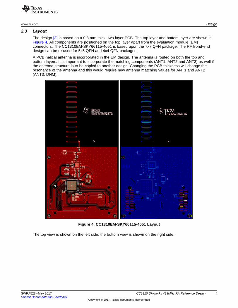
2.3 LayoutThe design [3] is based on a 0.8 mm thick, two-layer PCB. The top layer and bottom layer are shown inFigure 4. All components are positioned on the top layer apart from the evaluation module (EM)connectors. The CC1310EM-SKY66115-4051 is based upon the 7x7 QFN package. The RF frond-enddesign can be re-used for 5x5 QFN and 4x4 QFN packages.
A PCB helical antenna is incorporated in the EM design. The antenna is routed on both the top andbottom layers. It is important to incorporate the matching components (ANT1, ANT2 and ANT3) as well ifthe antenna structure is to be copied to another design. Changing the PCB thickness will change theresonance of the antenna and this would require new antenna matching values for ANT1 and ANT2(ANT3: DNM).
Figure 4. CC1310EM-SKY66115-4051 Layout
The top view is shown on the left side; the bottom view is shown on the right side.
Design www.ti.com
6 SWRA528–May 2017Submit Documentation Feedback
Copyright © 2017, Texas Instruments Incorporated
CC1310 Skyworks 433MHz PA Reference Design
2.4 SmartRF™ StudioTo evaluate the reference design it is recommended to use the EM on the SmartRF06EB with SmartRFStudio software. The supported functions are continuously being updated and the software can bedownloaded [6].
With SmartRF studio 7 (version 2.4.3), new features have been added to support 433 MHz – 510 MHzreference designs.• Default recommended setting on 430-510MHz band.• DIOs configuration based on the truth table of the FEM.• RF front-end mode configuration.
For more information on SmartRF Studio7, see http://www.ti.com/tool/smartrftm-studio. Figure 5, Figure 6and Figure 7 illustrate how to configure the CC1310EM-SKY66115-4051 board.
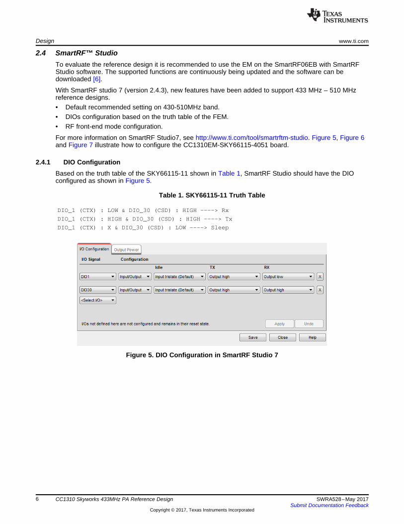
2.4.1 DIO ConfigurationBased on the truth table of the SKY66115-11 shown in Table 1, SmartRF Studio should have the DIOconfigured as shown in Figure 5.
Table 1. SKY66115-11 Truth Table
DIO_1 (CTX) : LOW & DIO_30 (CSD) : HIGH ----> Rx
DIO_1 (CTX) : HIGH & DIO_30 (CSD) : HIGH ----> Tx
DIO_1 (CTX) : X & DIO_30 (CSD) : LOW ----> Sleep
Figure 5. DIO Configuration in SmartRF Studio 7
www.ti.com Design
7SWRA528–May 2017Submit Documentation Feedback
Copyright © 2017, Texas Instruments Incorporated
CC1310 Skyworks 433MHz PA Reference Design
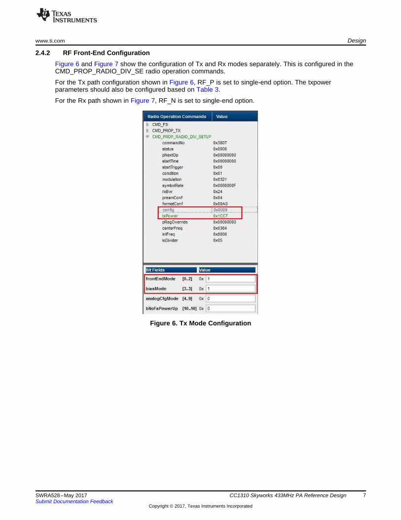
2.4.2 RF Front-End ConfigurationFigure 6 and Figure 7 show the configuration of Tx and Rx modes separately. This is configured in theCMD_PROP_RADIO_DIV_SE radio operation commands.
For the Tx path configuration shown in Figure 6, RF_P is set to single-end option. The txpowerparameters should also be configured based on Table 3.
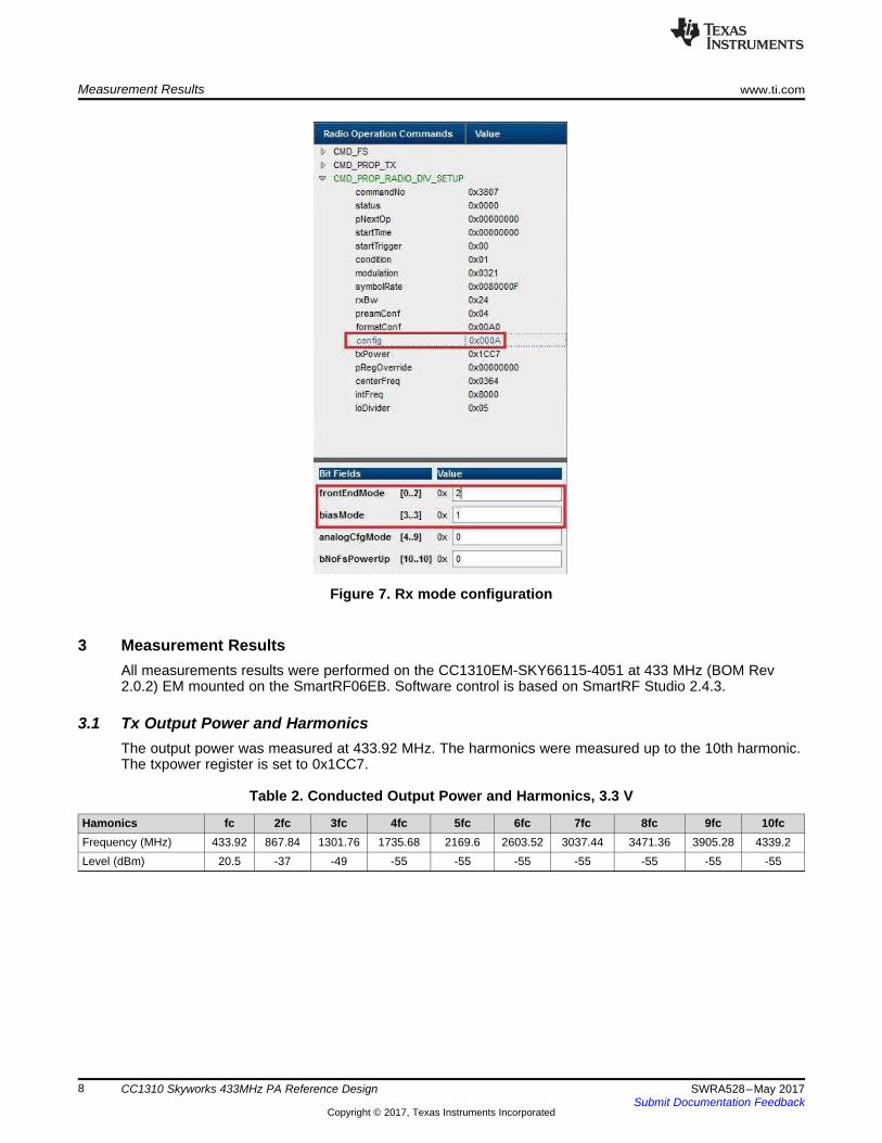
For the Rx path shown in Figure 7, RF_N is set to single-end option.
Figure 6. Tx Mode Configuration
Measurement Results www.ti.com
8 SWRA528–May 2017Submit Documentation Feedback
Copyright © 2017, Texas Instruments Incorporated
CC1310 Skyworks 433MHz PA Reference Design
Figure 7. Rx mode configuration
3 Measurement ResultsAll measurements results were performed on the CC1310EM-SKY66115-4051 at 433 MHz (BOM Rev2.0.2) EM mounted on the SmartRF06EB. Software control is based on SmartRF Studio 2.4.3.
3.1 Tx Output Power and HarmonicsThe output power was measured at 433.92 MHz. The harmonics were measured up to the 10th harmonic.The txpower register is set to 0x1CC7.
Table 2. Conducted Output Power and Harmonics, 3.3 V
Hamonics fc 2fc 3fc 4fc 5fc 6fc 7fc 8fc 9fc 10fcFrequency (MHz) 433.92 867.84 1301.76 1735.68 2169.6 2603.52 3037.44 3471.36 3905.28 4339.2Level (dBm) 20.5 -37 -49 -55 -55 -55 -55 -55 -55 -55
www.ti.com Measurement Results
9SWRA528–May 2017Submit Documentation Feedback
Copyright © 2017, Texas Instruments Incorporated
CC1310 Skyworks 433MHz PA Reference Design
3.2 Tx Output Power Dynamic Range and Current ConsumptionOutput power and current consumption were measured across the power table at 433.92 MHz. Theaverage results are shown in Table 3.
In the CMD_PROP_RADIO_DIV_SETUP, the power can be configured in the txpower register, which isshown in Figure 6.
Table 3. TX Output Power, Current Consumption vs. Power Table, 3.3 V
Power Table 0x08C0 0x0041 0x10C3 0x1043 0x14C4 0x18C5 0x18C6 0x1CC7Output power 12.3 16.3 18 18.9 19.3 19.6 19.8 20 dBmCurrentconsumption
52 62.8 71.4 75.9 78.1 79.7 81.6 82.4 mA
The SKY66115-11 maximum input power rating on the PIN_TX is limited to 10dBm. CC1310 should limitthe TX Power control IB bit of txpower register below 0x07.
3.3 Rx Current ConsumptionThe static Rx current consumption was measured at 6.3 mA with 3.3 V power supply.
3.4 SensitivityThe sensitivity was measured with 50 kbps datarate setting on CC1310EM-SKY66115-4051 at 433 MHz(BOM Rev 2.0.2) to -106.4 dBm during normal temperature and 3.3 V power supply.
If the data rate is reduced from 50 kbps and Long Range Mode utilized, then the following sensitivitylevels can be achieved on the on CC1310EM-SKY66115-4051 at 433 MHz (BOM Rev 2.0.2) Ref Design:
● 5 kbps sensitivity: -117 dBm● 2.5 kbps sensitivity: -119 dBm● 1.25 kbps sensitivity: -120 dBm● 0.625 kbps sensitivity: -121 dBm
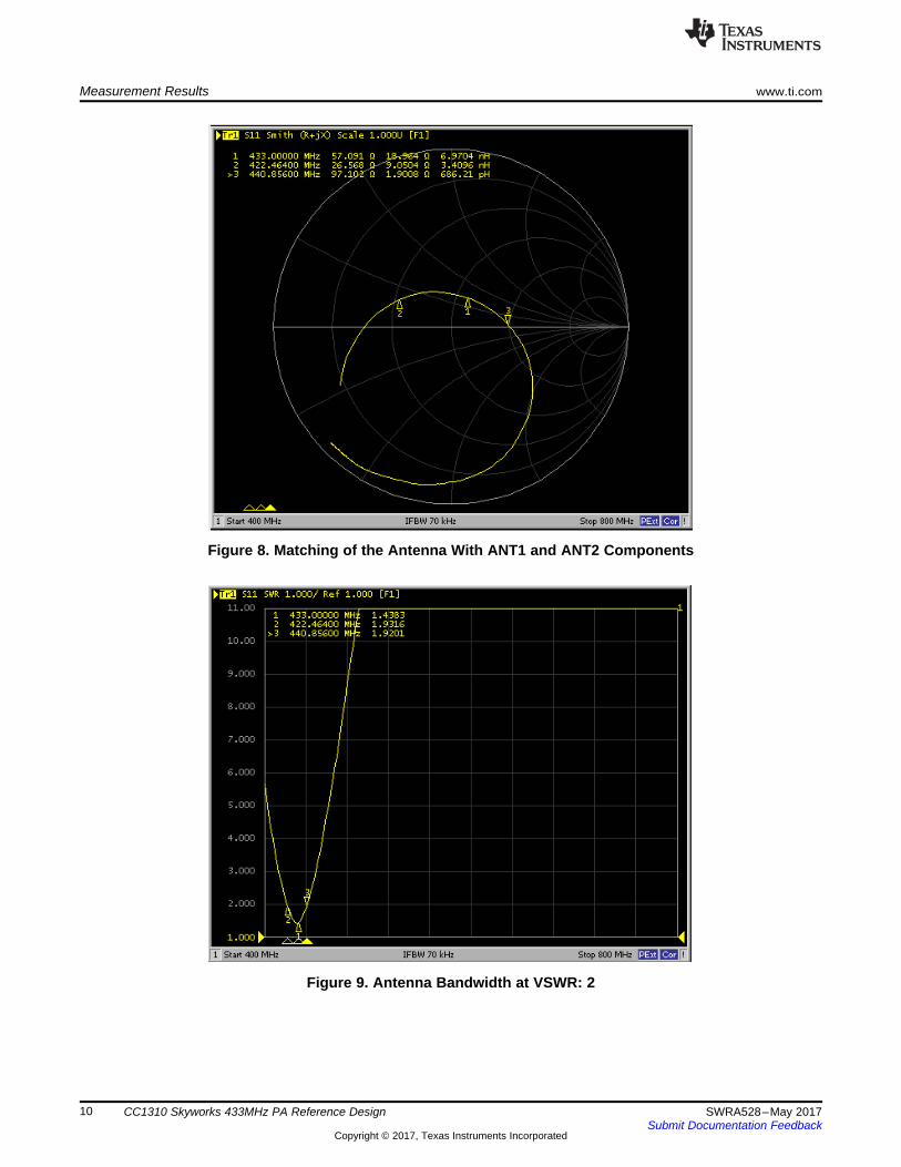
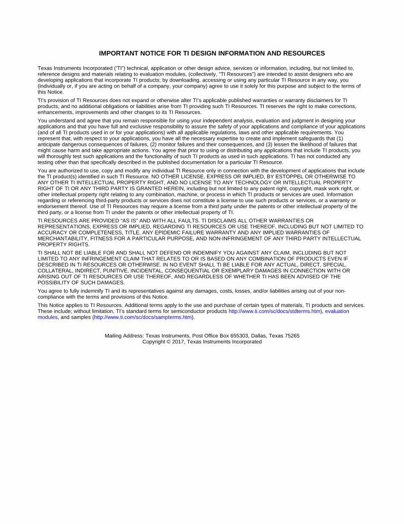
3.5 Antenna DesignThe PCB helical antenna shown in Figure 4 has been matched to 433.92 MHz with ANT 1: 6.8 pF andANT2: 91 nH. For more information, see Figure 8. The antenna is matched for the complete band of 470MHz – 510 MHz. For more information, see Figure 8 and Figure 9.
This antenna design, matching tuning and testing results are based on the CC1310EM-SKY66115-4051board at 433 MHz (BOM Rev 2.0.2) plugging on the SmartRF06EB board with the free spaceenvironment. In antenna design theory, some of the nearby materials will impact the antennaperformances, for example, grounded conductor, plastic/rubber cases, and so forth. For a realistic productantenna design, it is necessary to consider the mechanical case impacts and do proper tuning.
Measurement Results www.ti.com
10 SWRA528–May 2017Submit Documentation Feedback
Copyright © 2017, Texas Instruments Incorporated
CC1310 Skyworks 433MHz PA Reference Design
Figure 8. Matching of the Antenna With ANT1 and ANT2 Components
Figure 9. Antenna Bandwidth at VSWR: 2

www.ti.com Summary
11SWRA528–May 2017Submit Documentation Feedback
Copyright © 2017, Texas Instruments Incorporated
CC1310 Skyworks 433MHz PA Reference Design
4 SummaryThe CC1310EM-SKY66115-4051 reference design at 433 MHz (BOM Rev 2.0.2) is a low cost, easy-to-use, high efficiency solution with 20 dBm output power for 3.3 V supply. Tx current consumption at 20dBm is approximately 82 mA. The antenna is also integrated into the PCB that provides a compact,costless antenna solution.
5 References1. Achieving Optimum Radio Range (SWRA479)2. CC1310 SimpleLink™ Ultra-Low-Power Sub-1 GHz Wireless MCU Data Sheet (SWRS181)3. CC1310EM-SKY66115-4051 Reference Design (Rev: 2.0.x) (SWRC334)4. SKY66115 -11 Data Sheet5. Antenna Quick Guide (SWRA351)6. SmartRF Studio Download7. CC1310 Front-end Configurations Wiki page8. CC13xxEM-7XD-4251 Rev1_1_1
IMPORTANT NOTICE FOR TI DESIGN INFORMATION AND RESOURCES
Texas Instruments Incorporated (‘TI”) technical, application or other design advice, services or information, including, but not limited to,reference designs and materials relating to evaluation modules, (collectively, “TI Resources”) are intended to assist designers who aredeveloping applications that incorporate TI products; by downloading, accessing or using any particular TI Resource in any way, you(individually or, if you are acting on behalf of a company, your company) agree to use it solely for this purpose and subject to the terms ofthis Notice.TI’s provision of TI Resources does not expand or otherwise alter TI’s applicable published warranties or warranty disclaimers for TIproducts, and no additional obligations or liabilities arise from TI providing such TI Resources. TI reserves the right to make corrections,enhancements, improvements and other changes to its TI Resources.You understand and agree that you remain responsible for using your independent analysis, evaluation and judgment in designing yourapplications and that you have full and exclusive responsibility to assure the safety of your applications and compliance of your applications(and of all TI products used in or for your applications) with all applicable regulations, laws and other applicable requirements. Yourepresent that, with respect to your applications, you have all the necessary expertise to create and implement safeguards that (1)anticipate dangerous consequences of failures, (2) monitor failures and their consequences, and (3) lessen the likelihood of failures thatmight cause harm and take appropriate actions. You agree that prior to using or distributing any applications that include TI products, youwill thoroughly test such applications and the functionality of such TI products as used in such applications. TI has not conducted anytesting other than that specifically described in the published documentation for a particular TI Resource.You are authorized to use, copy and modify any individual TI Resource only in connection with the development of applications that includethe TI product(s) identified in such TI Resource. NO OTHER LICENSE, EXPRESS OR IMPLIED, BY ESTOPPEL OR OTHERWISE TOANY OTHER TI INTELLECTUAL PROPERTY RIGHT, AND NO LICENSE TO ANY TECHNOLOGY OR INTELLECTUAL PROPERTYRIGHT OF TI OR ANY THIRD PARTY IS GRANTED HEREIN, including but not limited to any patent right, copyright, mask work right, orother intellectual property right relating to any combination, machine, or process in which TI products or services are used. Informationregarding or referencing third-party products or services does not constitute a license to use such products or services, or a warranty orendorsement thereof. Use of TI Resources may require a license from a third party under the patents or other intellectual property of thethird party, or a license from TI under the patents or other intellectual property of TI.TI RESOURCES ARE PROVIDED “AS IS” AND WITH ALL FAULTS. TI DISCLAIMS ALL OTHER WARRANTIES ORREPRESENTATIONS, EXPRESS OR IMPLIED, REGARDING TI RESOURCES OR USE THEREOF, INCLUDING BUT NOT LIMITED TOACCURACY OR COMPLETENESS, TITLE, ANY EPIDEMIC FAILURE WARRANTY AND ANY IMPLIED WARRANTIES OFMERCHANTABILITY, FITNESS FOR A PARTICULAR PURPOSE, AND NON-INFRINGEMENT OF ANY THIRD PARTY INTELLECTUALPROPERTY RIGHTS.TI SHALL NOT BE LIABLE FOR AND SHALL NOT DEFEND OR INDEMNIFY YOU AGAINST ANY CLAIM, INCLUDING BUT NOTLIMITED TO ANY INFRINGEMENT CLAIM THAT RELATES TO OR IS BASED ON ANY COMBINATION OF PRODUCTS EVEN IFDESCRIBED IN TI RESOURCES OR OTHERWISE. IN NO EVENT SHALL TI BE LIABLE FOR ANY ACTUAL, DIRECT, SPECIAL,COLLATERAL, INDIRECT, PUNITIVE, INCIDENTAL, CONSEQUENTIAL OR EXEMPLARY DAMAGES IN CONNECTION WITH ORARISING OUT OF TI RESOURCES OR USE THEREOF, AND REGARDLESS OF WHETHER TI HAS BEEN ADVISED OF THEPOSSIBILITY OF SUCH DAMAGES.You agree to fully indemnify TI and its representatives against any damages, costs, losses, and/or liabilities arising out of your non-compliance with the terms and provisions of this Notice.This Notice applies to TI Resources. Additional terms apply to the use and purchase of certain types of materials, TI products and services.These include; without limitation, TI’s standard terms for semiconductor products http://www.ti.com/sc/docs/stdterms.htm), evaluationmodules, and samples (http://www.ti.com/sc/docs/sampterms.htm).
Mailing Address: Texas Instruments, Post Office Box 655303, Dallas, Texas 75265Copyright © 2017, Texas Instruments Incorporated