cc-link master module (yokogawa electric plc … · m-system famclcfg is used to program parameters...
TRANSCRIPT

1FAMCLCFG USERS MANUAL EM-9032
CC-LINK MASTER MODULE(YOKOGAWA ELECTRIC PLC USE)PC CONFIGURATOR SOFTWARE
Model: FAMCLCFG
USERS MANUAL

2FAMCLCFG USERS MANUAL EM-9032
Contents
1. INTRODUCTION .....................................................................................4
1.1 GENERAL DESCRIPTION ...................................................................................................4
1.2 CORRESPONDING VERSION .............................................................................................4
1.3 PC REQUIREMENTS ...........................................................................................................4
1.4 NUMBER OF CONNECTABLE MODULES ..........................................................................4
1.5 DRIVER SOFTWARE ...........................................................................................................4
1.6 INSTALLING & DELETING THE PROGRAM ........................................................................4
2. GETTING STARTED ..............................................................................5
2.1 FILE (F) MENU .....................................................................................................................5
2.1.1 FILE (F) > OPEN (O) ................................................................................................5
2.1.2 FILE (F) > SAVE (S) ..................................................................................................5
2.1.3 FILE (F) > SAVE AS (A) ............................................................................................5
2.1.4 FILE (F) > OPEN CSV FILE (C) ................................................................................5
2.1.5 FILE (F) > SAVE CSV FILE (V) .................................................................................5
2.2 EDIT (E) MENU ....................................................................................................................6
2.2.1 EDIT (E) > MASTER STATION (M) > SETTING (S) .................................................6
2.2.2 EDIT (E) > SLAVE STATION (S) > ADD BY CSP (V) ...............................................6
2.2.3 EDIT (E) > SLAVE STATION (S) > ADD BY CSP+ (P) .............................................8
2.2.4 EDIT (E) > SLAVE STATION (S) > ADD GENERIC DEVICE (N) .............................9
2.2.5 EDIT (E) > SLAVE STATION (S) > DELETE (D) .......................................................9
2.3 ONLINE (T) MENU ............................................................................................................. 10
2.3.1 ONLINE (T) > COM SETTING (S) .......................................................................... 10
2.3.2 ONLINE (T) > CONNECT (C) .................................................................................13
2.3.3 ONLINE (T) > DISCONNECT (D) ...........................................................................13
2.3.4 ONLINE (T) > MONITOR SLAVE STATION (M) .....................................................14
2.4 LANGUAGE (L) MENU .......................................................................................................16
2.5 BASIC VIEW (MASTER STATION) .....................................................................................17
2.5.1 UNIT NO., SLOT NO ..............................................................................................17
2.5.2 NUMBER OF CONNECTED STATIONS ................................................................17
2.5.3 RETRY COUNT ......................................................................................................18
2.5.4 AUTOMATIC RECONNECTION STATION COUNT ................................................18
2.5.5 TRANSMISSION SPEED .......................................................................................18
2.5.6 OPERATION MODE WHEN CPU IS DOWN ..........................................................18
2.5.7 INPUT FROM DATA LINK ERROR STATION .........................................................18
2.5.8 AUTO STATION NO. ASSIGNMENT .......................................................................19
2.5.9 UPLOAD, DOWNLOAD ..........................................................................................19
2.6 BASIC VIEW (SLAVE STATION).........................................................................................20
2.6.1 STATION NO. ..........................................................................................................20
2.6.2 DEVICE MODEL NUMBER ....................................................................................20
2.6.3 DEVICE TYPE ........................................................................................................20
2.6.4 STATION TYPE .......................................................................................................20
2.6.5 DEVICE COMMENT ...............................................................................................20
2.6.6 VENDOR ................................................................................................................21

3FAMCLCFG USERS MANUAL EM-9032
2.6.7 RESERVED/ERROR INVALID STATION ................................................................21
2.6.8 CC-LINK VERSION ................................................................................................21
2.6.9 NUMBER OF OCCUPIED STATIONS ....................................................................21
2.6.10 EXPANDED CYCLIC SETTING ............................................................................21
2.6.11 REMOTE STATION POINTS RX/RY .....................................................................21
2.6.12 REMOTE STATION POINTS RWw/RWr ...............................................................21
3. FAMCLCFG FILES ...............................................................................22
3.1 FAMCLCFG FOLDERS ......................................................................................................22
3.2 CSP FILES .........................................................................................................................22
3.3 CSP+ FILES .......................................................................................................................22
3.4 CONFIGURATION FILES ...................................................................................................22
4. REMAKRS ............................................................................................23
4.1 SLAVE SETTINGS TO BE SAVED AND DISPLAY ITEMS .................................................23
4.2 VERSION HISTORY ...........................................................................................................23
5. APPENDIX ..........................................................................................24
5.1 APPENDIX 1 GENERIC TERMS AND ABBREVIATIONS .................................................24
5.2 APPENDIX 2 TROUBLESHOOTING .................................................................................25
5.3 APPENDIX 3 CSV FILE FORMAT .....................................................................................26

4FAMCLCFG USERS MANUAL EM-9032
1. INTRODUCTION
1.1 GENERAL DESCRIPTION
M-System FAMCLCFG is used to program parameters for the model FAMCL CC-Link Master Module (Yokogawa Electric PLC FA-M3 use). The following major functions are available:1) Edit parameters2) Download parameters to the device, upload parameters from the device3) Save parameters as files, read parameters from files
1.2 CORRESPONDING VERSION
This users manual supports the FAMCLCFG Ver. 1.01.XX.
1.3 PC REQUIREMENTS
The following PC performance is required for adequate operation of the software program.
PC IBM PC compatible
OS
Windows 7 (SP1) (32-bit, 64-bit)
Windows 8.1 (32-bit, 64-bit) *Windows RT is not included.
The software may not operate adequately in certain conditions.
CPU Must meet the relevant Windows’ requirements.
Memory
Communication port COM port (COM1 through COM32)
Programming tool PC with the FA-M3 Programming Tool WideField3 (R.3.02 or later)
1.4 NUMBER OF CONNECTABLE MODULES
The FAMCLCFG recognizes maximum 2 units of FAMCL on a FA-M3 main unit, and does not recognize the FAMCL on a sub unit.
1.5 DRIVER SOFTWARE
The FAMCLCFG runs on the PC where the FA-M3 Programming Tool WideField3*1 (R.3.02 or later) is installed. *1. FA-M3 Programming Tool provided by Yokogawa Electric Corporation
1.6 INSTALLING & DELETING THE PROGRAM
INSTALLThe program is provided as compressed archive. Decompress the archive and execute ‘setup.exe’ to start up the FAM-CLCFG installer program. Follow instructions on the Windows.Log on as administrator to start installation.
DELETEFor Windows 7 and 8.1, open Control Panel > Uninstall a program, or Uninstall or change a program. Select the FAMCLcfg from the program list and click Uninstall button.

5FAMCLCFG USERS MANUAL EM-9032
2. GETTING STARTEDOpen the FAMCLCFG on the Windows PC.
2.1 FILE (F) MENU
2.1.1 FILE (F) > OPEN (O)Open an existing configuration file.Not usable in selecting a slave station.
2.1.2 FILE (F) > SAVE (S)Overwrite and save current master station settings.Usable after Open or Save As.
2.1.3 FILE (F) > SAVE AS (A)Name and save current master station settings.
2.1.4 FILE (F) > OPEN CSV FILE (C)Open a configuration file in a CSV text format.Not usable in selecting a slave station.
2.1.5 FILE (F) > SAVE CSV FILE (V)Save current master station settings to a CSV text format file.
CAUTION
A CSV text format file can be read and edited on other application software. Note the followings:
1. The character code in CSV files is Unicode (UTF-8).
Application software needs to conform to Unicode (UTF-8) to edit the files.
2. When increasing or decreasing the number of connected slave stations in editing, also modify
the item ‘number of connected stations’ .

6FAMCLCFG USERS MANUAL EM-9032
2.2 EDIT (E) MENU
2.2.1 EDIT (E) > MASTER STATION (M) > SETTING (S)Select the above menu, and the master station view will appear.
2.2.2 EDIT (E) > SLAVE STATION (S) > ADD BY CSP (V)Set a slave station using a CSP file.Select the above menu, and the following window will appear.Select a device and click [OK] button.
CSP �les (device models) are listed.
Click to select.
Information of the selected CSP �le is shown.

7FAMCLCFG USERS MANUAL EM-9032
2.2.2.1 VENDOR
Select a Vendor and their CSP files will be listed.
2.2.2.2 DEVICE TYPE
Select a device type and its CSP files will be listed.
2.2.2.3 UPDATING CSP FILE INFORMATION
When new CSP files are saved in the CSP folder, click [Update] button to update the vendor information files.

8FAMCLCFG USERS MANUAL EM-9032
2.2.3 EDIT (E) > SLAVE STATION (S) > ADD BY CSP+ (P)Set a slave station using a CSP+ file.Select the above menu, and the following window will appear.Select a device and setting, and click [OK] button.
When a CSP + �le has plural settings, select one.
2.2.3.1 UPDATING CSP+ FILE INFORMATION
When new CSP+ files are saved in the CSPP folder, click [Update] button to update the vendor information files.

9FAMCLCFG USERS MANUAL EM-9032
2.2.4 EDIT (E) > SLAVE STATION (S) > ADD GENERIC DEVICE (N)Use when CSP and CSP+ files do not exist.
2.2.4.1 STATION TYPE
Select one among following 3 station types: (1) Remote I/O station (2) Remote device station (CC-Link Ver.1.XX) (3) Remote device station (CC-Link Ver.2.XX)After selecting a station type, set ‘number of occupied stations’ and ‘expanded cyclic setting’ (with Ver. 2 only) in the slave station view.
Example: To connect M-System’ s Remote I/O model R3-NC3,
- Select ‘remote device station (CC-Link Ver. 2)’ in the dialog box ‘Add Generic Device’ .
- Set ‘number of occupied stations’ to 4 in the slave station view.
- Set ‘station No.’ and ‘expanded cyclic setting’ in the slave station view to those set with the
switches on the R3-NC3.
2.2.5 EDIT (E) > SLAVE STATION (S) > DELETE (D)Delete a selected slave station. The slave station numbers will be closed up to reassign.Deleting the master station is not available.
10FAMCLCFG USERS MANUAL EM-9032
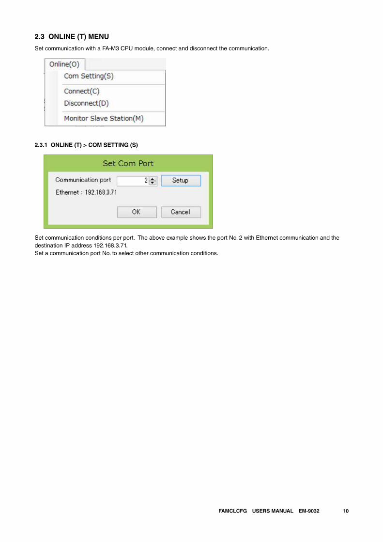
2.3 ONLINE (T) MENU
Set communication with a FA-M3 CPU module, connect and disconnect the communication.
2.3.1 ONLINE (T) > COM SETTING (S)
Set communication conditions per port. The above example shows the port No. 2 with Ethernet communication and the destination IP address 192.168.3.71. Set a communication port No. to select other communication conditions.

11FAMCLCFG USERS MANUAL EM-9032
2.3.1.1 ONLINE (T) > COM SETTING (S) > [SETUP] BUTTONSet communication conditions of the selected port No.
2.3.1.2 MEDIASelect a medium.- USB- RS-232C (when using KM13)- Ethernet
2.3.1.3 USB COMMUNICATION - CONNECTION TIMEOUTTimeout (second) in connecting communication. 10 seconds fixed.
2.3.1.4 USB COMMUNICATION - CPU MODULESet the destination CPU module No.Set to 0, and the CPU module to which the USB cable is connected will be connected.(Setting range: 0 to 4)

12FAMCLCFG USERS MANUAL EM-9032
2.3.1.5 RS-232C COMMUNICATION - COMMUNICATION METHODSelect ‘automatic recognition’ or ‘fixed’.With ‘automatic recognition’, the settings including baud rate are configured automatically.With ‘fixed’, select communication conditions from the drop-down list.
2.3.1.6 RS-232C COMMUNICATION - COMMUNICATION TIMEOUTSet timeout for the RS-232C communication.(Setting range: 1 to 100 seconds)
2.3.1.7 RS-232C COMMUNICATION - COM PORTSet COM port No. of the PC for the RS-232C communication.(COM1 to COM32)
2.3.1.8 RS-232C COMMUNICATION - NUMBER OF RETRIESSet number of times to retry the RS-232C communication.(Setting range: 0 to 100)
2.3.1.9 ETHERNET COMMUNICATION - DESTINATION IP ADDRESSSet IP address of a destination CPU module.
2.3.1.10 ETHERNET COMMUNICATION - CPU MODULESet destination CPU module No.(Setting range: 1 to 4)
2.3.1.11 ETHERNET COMMUNICATION - CONNECTION TIMEOUTSet timeout in connecting.(Setting range: 1 to 120 seconds)
13FAMCLCFG USERS MANUAL EM-9032
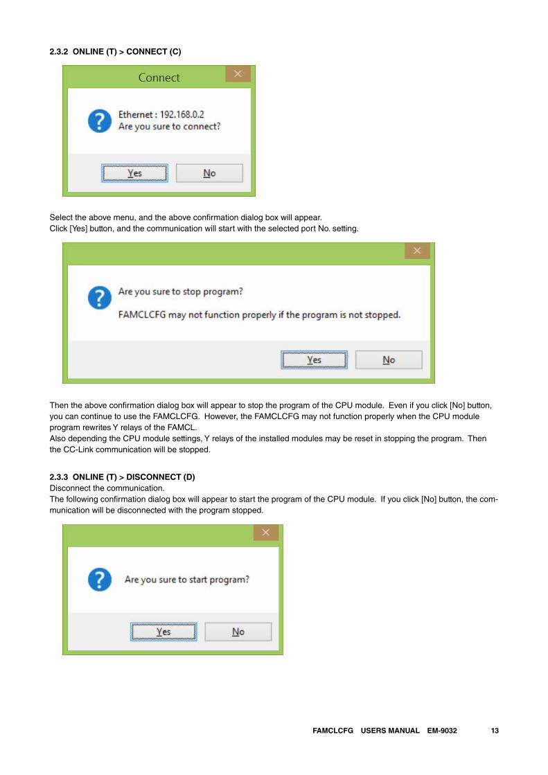
2.3.2 ONLINE (T) > CONNECT (C)
Select the above menu, and the above confirmation dialog box will appear.Click [Yes] button, and the communication will start with the selected port No. setting.
Then the above confirmation dialog box will appear to stop the program of the CPU module. Even if you click [No] button, you can continue to use the FAMCLCFG. However, the FAMCLCFG may not function properly when the CPU module program rewrites Y relays of the FAMCL.Also depending the CPU module settings, Y relays of the installed modules may be reset in stopping the program. Then the CC-Link communication will be stopped.
2.3.3 ONLINE (T) > DISCONNECT (D)Disconnect the communication.The following confirmation dialog box will appear to start the program of the CPU module. If you click [No] button, the com-munication will be disconnected with the program stopped.

14FAMCLCFG USERS MANUAL EM-9032
2.3.4 ONLINE (T) > MONITOR SLAVE STATION (M)When the CC-Link communication is disconnected, the following confirmation dialog box will appear to connect the com-munication.If you click [No] button, monitoring will not be available.
The selected slave station information will appear (and be updated approximately every second).
Master station to monitor Slave station to monitor
Select data to monitor
Monitor view

15FAMCLCFG USERS MANUAL EM-9032
- Rx monitor
- RWr monitor
Click [OK] button to quit the monitor. The confirmation dialog box will appear to disconnect the CC-Link communication.

16FAMCLCFG USERS MANUAL EM-9032
If you click [No] button, the CC-Link communication will not be disconnected and continue.* When an error occurs in starting the CC-Link communication and the ERR LED turns on, it will not turn off even when the communica-
tion is disconnected. It turns on until the CC-Link is normally communicated.
2.4 LANGUAGE (L) MENU
Set a language, and the setting will be enabled at the next startup.

17FAMCLCFG USERS MANUAL EM-9032
2.5 BASIC VIEW (MASTER STATION)
The following view appears after startup, where the master station is selected.
Application and version No.
Communication status,
CPU module model
CC-Link con�guration of the master station
(FAMCL) and slave stations.
Select a station.
Settings of master station (FAMCL) or
Slave stations.
Con�gure the settings.
Menu bar
2.5.1 UNIT NO., SLOT NO
The unit No. and slot No. of the selected master station are indicated.Unit No. 0 to 7Slot No. 1 to 16The information is taken from the CPU module in connecting communication.
2.5.2 NUMBER OF CONNECTED STATIONS
Total number of the slave stations set in the selected master station is indicated.Not modifiable.

18FAMCLCFG USERS MANUAL EM-9032
2.5.3 RETRY COUNT
Set number of times to retry polling a slave station when it does not reply.(Setting range: 1 to 7)
2.5.4 AUTOMATIC RECONNECTION STATION COUNT
Set number of slave stations to reconnect by a single link scan when data link error stations are reconnected.(Setting range: 1 to 10)
2.5.5 TRANSMISSION SPEED
The transmission speed of the CC-Link system set in the master station is indicated.The transmission speed of the FAMCL is set with the rotary switch on the device and is not configurable with the FAM-CLCFG.
2.5.6 OPERATION MODE WHEN CPU IS DOWN
Set the CC-Link communication when a CPU error of the FAMCL occurs.Stop .............. The CC-Link data link communication is stopped when a CPU error occurs.Continue ....... The CC-Link data link communication continues when a CPU error occurs.
2.5.7 INPUT FROM DATA LINK ERROR STATION
Set input data processing from a data link error station.Clear input data ........ The input from the data link error station is cleared. (RX area cleared, RWr area not cleared)Hold input data ......... The input from the data link error station is held.
19FAMCLCFG USERS MANUAL EM-9032
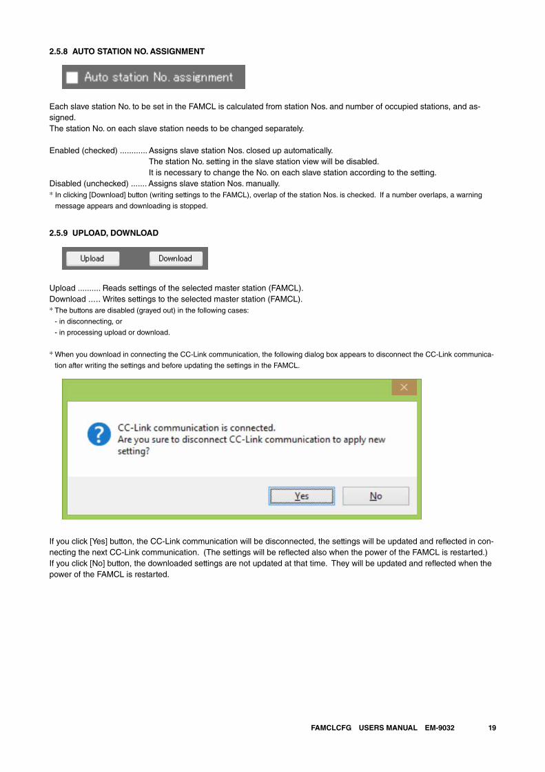
2.5.8 AUTO STATION NO. ASSIGNMENT
Each slave station No. to be set in the FAMCL is calculated from station Nos. and number of occupied stations, and as-signed.The station No. on each slave station needs to be changed separately.
Enabled (checked) ............ Assigns slave station Nos. closed up automatically. The station No. setting in the slave station view will be disabled. It is necessary to change the No. on each slave station according to the setting.
Disabled (unchecked) ....... Assigns slave station Nos. manually.* In clicking [Download] button (writing settings to the FAMCL), overlap of the station Nos. is checked. If a number overlaps, a warning
message appears and downloading is stopped.
2.5.9 UPLOAD, DOWNLOAD
Upload .......... Reads settings of the selected master station (FAMCL).Download ..... Writes settings to the selected master station (FAMCL).* The buttons are disabled (grayed out) in the following cases:
- in disconnecting, or
- in processing upload or download.
* When you download in connecting the CC-Link communication, the following dialog box appears to disconnect the CC-Link communica-
tion after writing the settings and before updating the settings in the FAMCL.
If you click [Yes] button, the CC-Link communication will be disconnected, the settings will be updated and reflected in con-necting the next CC-Link communication. (The settings will be reflected also when the power of the FAMCL is restarted.)If you click [No] button, the downloaded settings are not updated at that time. They will be updated and reflected when the power of the FAMCL is restarted.
20FAMCLCFG USERS MANUAL EM-9032
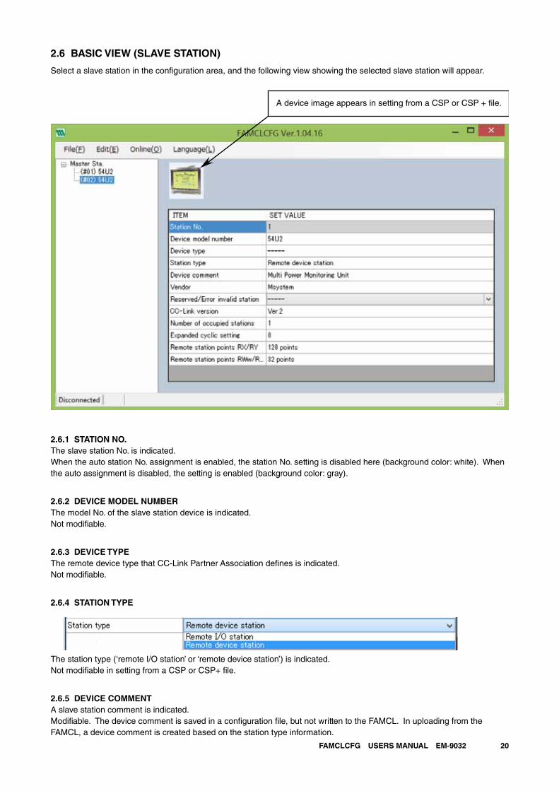
2.6 BASIC VIEW (SLAVE STATION)
Select a slave station in the configuration area, and the following view showing the selected slave station will appear.
A device image appears in setting from a CSP or CSP + le.
2.6.1 STATION NO.The slave station No. is indicated.When the auto station No. assignment is enabled, the station No. setting is disabled here (background color: white). When the auto assignment is disabled, the setting is enabled (background color: gray).
2.6.2 DEVICE MODEL NUMBERThe model No. of the slave station device is indicated.Not modifiable.
2.6.3 DEVICE TYPEThe remote device type that CC-Link Partner Association defines is indicated.Not modifiable.
2.6.4 STATION TYPE
The station type (‘remote I/O station’ or ‘remote device station’) is indicated.Not modifiable in setting from a CSP or CSP+ file.
2.6.5 DEVICE COMMENTA slave station comment is indicated.Modifiable. The device comment is saved in a configuration file, but not written to the FAMCL. In uploading from the FAMCL, a device comment is created based on the station type information.

21FAMCLCFG USERS MANUAL EM-9032
2.6.6 VENDORA vendor of the slave station is indicated. Without vendor information, ‘-----‘ is indicated.Not modifiable.
2.6.7 RESERVED/ERROR INVALID STATION
Set the slave station as a reserved or error invalid station. Otherwise set ‘-----‘.Modifiable.
2.6.8 CC-LINK VERSION
Set the CC-Link version No.Not modifiable in setting from a CSP or CSP+ file.
2.6.9 NUMBER OF OCCUPIED STATIONS
Set number of occupied stations.Not modifiable in setting from a CSP or CSP+ file.
2.6.10 EXPANDED CYCLIC SETTING
Set expanded cyclic.Configurable only with the CC-Link Ver. 2.Not modifiable in setting from a CSP or CSP+ file.
2.6.11 REMOTE STATION POINTS RX/RYMaximum number of points by the number of occupied stations and expanded cyclic is indicated.Not modifiable.
2.6.12 REMOTE STATION POINTS RWw/RWrMaximum number of points by the number of occupied stations and expanded cyclic is indicated.Not modifiable.
CAUTION
In adding a slave station from a CSP or CSP+ file, the items other than ‘station No.’ and
‘reserved/error invalid station’ are not modiable.
Besides them, ‘CC-Link version’ , ‘number of occupied stations’ and ‘expanded cyclic setting’
are also modifiable for an uploaded slave station.

22FAMCLCFG USERS MANUAL EM-9032
3. FAMCLCFG FILES
3.1 FAMCLCFG FOLDERS
The FAMCLCFG creates folders in the Documents folder in the PC in starting up, unless the FAMCLCFG folder already exists.
Folder configuration
FAMCLCFG CSP
CSPP
Image
SYS
3.2 CSP FILES
CSP files are definition files for the CC-Link devices.Save CSP files in the CSP folder.Save image (bmp) files in the Image folder.* Do not change the CSP and image file names.
3.3 CSP+ FILES
CSP+ files are definition files for the CC-Link devices.Save CSP+ files in the CSPP folder.Save image (bmp) files in the Image folder.* Do not change the CSP+ and image file names.
3.4 CONFIGURATION FILES
The extension of the configuration files the FAMCLCFG creates is cfg.
23FAMCLCFG USERS MANUAL EM-9032
4. REMAKRS
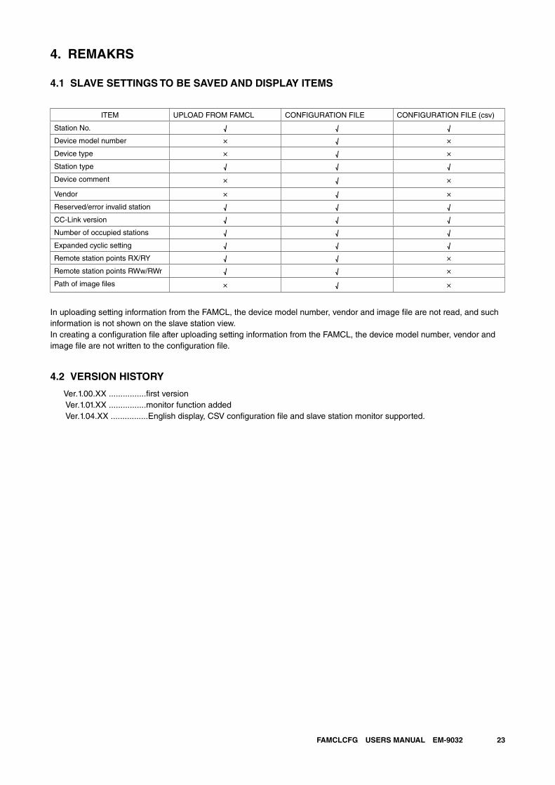
4.1 SLAVE SETTINGS TO BE SAVED AND DISPLAY ITEMS
ITEM UPLOAD FROM FAMCL CONFIGURATION FILE CONFIGURATION FILE (csv)
Station No. √ √ √
Device model number × √ ×
Device type × √ ×
Station type √ √ √
Device comment × √ ×
Vendor × √ ×
Reserved/error invalid station √ √ √
CC-Link version √ √ √
Number of occupied stations √ √ √
Expanded cyclic setting √ √ √
Remote station points RX/RY √ √ ×
Remote station points RWw/RWr √ √ ×
Path of image files × √ ×
In uploading setting information from the FAMCL, the device model number, vendor and image file are not read, and such information is not shown on the slave station view.In creating a configuration file after uploading setting information from the FAMCL, the device model number, vendor and image file are not written to the configuration file.
4.2 VERSION HISTORY
Ver.1.00.XX ................first version Ver.1.01.XX ................monitor function added Ver.1.04.XX ................English display, CSV configuration file and slave station monitor supported.

24FAMCLCFG USERS MANUAL EM-9032
5. APPENDIX
5.1 APPENDIX 1 GENERIC TERMS AND ABBREVIATIONS
This manual uses following abbreviations and terms.
GENERIC
TERM / ABBRIVIATION
DESCRIPTION
Master station The station that controls the entire CC-Link system. One master station is required per system and
the FAMCL is the master station. The station number for this station is fixed to 0.
Remote station A generic station name for remote I/O stations and remote device stations
Remote I/O station A remote station that handles bit unit data only
Remote device station A remote station that handles both bit unit and word unit data
Slave station Remote I/O station, remote device station and local station
Reserved station Slave stations that exist on the CC-Link network parameters set in the master station but are not ac-
tually connected. In setting reserved stations, the data link can be performed without error. (Data link
to the reserved stations is not performed.) Such a slave station, if not specified as a reserved station,
is treated as data link error station.
Error invalid station setting With this setting, a slave station that is powered off is not treated as data link error station.
Station A device that exists on the CC-Link system, where the station number assignment can be from 0 to
64.
Number of stations The total station numbers occupied by all slave stations connected in the CC-Link system
Station number The number assigned to each station connected to the CC-Link system
0: master station No.
1 to 64: slave station No.
Number of occupied stations The CC-Link system allows 32 points of bit data I/O respectively and 4 points of word data I/O
respectively per station. Each slave station needs to occupy a certain number of stations correspond-
ing to the information sent to or received from other stations, which is called number of occupied
stations.
Automatic reconnection A function that a unit not joining the data link due to power off recovers the normal status and auto-
matically joins the data link
RX Information entered in bit units from the remote station to the master station
RY Information output in bit units from the master station to the remote station
RWr Remote register (read area for CC-Link)
Information entered in 16-bit units from the remote device station to the master station
RWw Remote register (write area for CC-Link)
Information output in 16-bit units from the master station to the remote device station

25FAMCLCFG USERS MANUAL EM-9032
5.2 APPENDIX 2 TROUBLESHOOTING
PROBLEM CHECK ITEM REMEDY
Unable to perform data link for the
entire system.
Aren’t there any disconnected cables? Check the cable connection visually or with
continuity test.
Are the terminating resistors connected to
the terminal stations located at each end of
the CC-Link system?
Connect the supplied terminating resistors to
the terminal stations at each end of the CC-Link
system.
Are appropriate terminating resistors con-
nected?
Connect terminating resistors that match the
cable type to the terminal stations at each end of
the CC-Link system.
Doesn’t an error occur at the master sta-
tion?
Check the status indicator LEDs of the FAMCL.
Unable to receive input from a remote
I/O station.
Does the remote I/O station perform data
link?
Check the LED of the remote I/O station.
Is the slave station information set with the
FAMCLCFG correct?
Confirm that the following parameter conforms to
that of the station:
- Station type: remote I/O station
Does the transmission speed coincide with
that set with the FAMCL?
Check the transmission speed.
Does the master station recognize the
remote I/O station?
Select Online > Monitor slave station from the
menu of the FAMCLCFG to confirm.
Isn’t the station set as a reserved station? Check the settings of the slave station with the
FAMCLCFG.
Aren’t there any overlapped station num-
bers?
Check the station No. setting.
Unable to output data from a remote
I/O station.
Is data written to the correct address of
remote output RY (buffer memory)?
Check the sequence program.
Unable to receive data to the remote
register RWr in a remote
Does the remote device station perform
data link?
Check the LED of the remote device station.
Device station. Does the remote I/O station perform data
link?
Check the LED of the remote I/O station.
Is the slave station information set with the
FAMCLCFG correct?
Confirm that the following parameters conform to
those of the station:
- Station type: remote device station
- CC-Link version
- Number of occupied stations
- Expanded cyclic setting (in case of Ver. 2)
Does the transmission speed coincide with
that set with the FAMCL?
Check the transmission speed.
Does the master station recognize the
remote device station?
Select Online > Monitor slave station from the
menu of the FAMCLCFG to confirm.
Isn’t the station set as a reserved station? Check the settings of the slave station with the
FAMCLCFG.
Aren’t there any overlapped station num-
bers?
Check the station No. setting.
Unable to write data to the remote
register RWw in a remote device
station.
Is data written to the correct address of
remote register RWw (buffer memory)?
Check the sequence program.

26FAMCLCFG USERS MANUAL EM-9032
5.3 APPENDIX 3 CSV FILE FORMAT
This section describes the file format in saving settings as a CSV text format file.The character code is Unicode (UTF-8). In order to edit a file, use the software that can read and write the Unicode files.
1. application (FAMCLCFG), FAMCLCFG 2. file version (1), 1 3. Number of connected stations (1 - 64), 3 4. Retry count (1 - 7), 3 5. Automatic reconnection station count (1 - 10), 1 6. Operation mode when CPU is down (0:Stop / 1:Continue), 1 7. Input from data link error station (0:Clear / 1:Hold), 0 8. Station No. (1 - 64), Station type (0:Remote I/O / 1:Remote device), Reserved/Error invalid station (0:----- / 1:Re-
served / 2:Invalid), CC-Link version (1:Ver.1 / 2:Ver.2), Number of occupied station (1 - 4), Expanded cyclic setting (1/2/4/8)
9. 1,0,0,1,1,1 10. 2,1,0,1,1,1 11. 3,1,0,2,1,1
1 to 2: CSV file information. Do not modify. 3 to 7: Master (FAMCL) settings. Editable within the setting ranges.
8: Setting items of slave station9: Settings of the slave station No. 1. Editable within the setting ranges.
10 -: Settings of the slave station No. 2 and following stations. Editable within the setting ranges.* In increasing or decreasing the slave stations, also modify the item ‘number of connected stations’.