cb gf web in aug 2016, controls r2 8.23.16 final
TRANSCRIPT

BOILER FEED
WATER CONTROL
Presented by Cleaver Brooks’ Steve Connor
and Grundfos’ Jim Swetye

TODAY’S AGENDA
• Again address high pressure boilers (FT & IWT) in the 100 – 1200 HP range
• Where the water level is measured in these boilers
• The ways in which the pressure in the boiler and system is controlled
• Maintaining a reliable and safe level of water in the boiler is critical
• Ways in which the boiler water level is controlled
• Matching this control with (4) distinct pumping strategies
• A couple pump selection exercises
• Summary
• Q&A
2
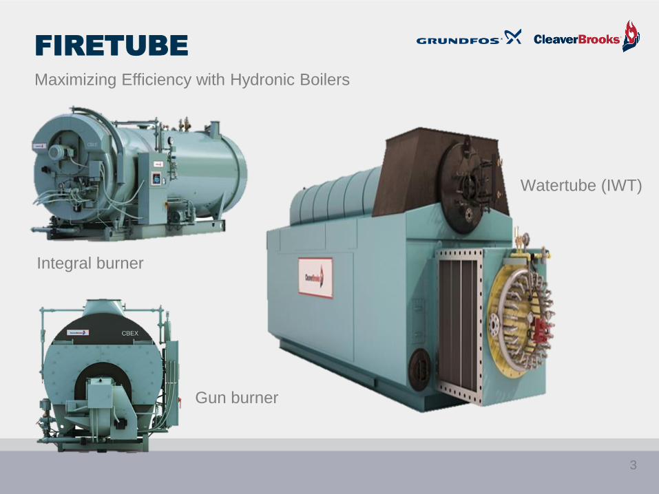
FIRETUBE
Watertube (IWT)
Integral burner
Gun burner
Maximizing Efficiency with Hydronic Boilers
3

BOILER SIZES AND
FEED PUMP SIZES
Boiler HP
Range
Boiler
Pressure
Range
Typical Feed
Pump Type
Typical
Max. Feed
Pump
Flow
Range
Typical
Max. Feed
Pump
Head
Where
Used?
100 to
1200
150 to 500
psi
Vertical
inline
multistage;
regenerative
turbines
10 to 125
gpm1250 feet
General
industry;
institutional;
universities;
some
commercial
buildings
4

WATERTUBE OR IWT
Maximizing Efficiency with Hydronic Boilers
5
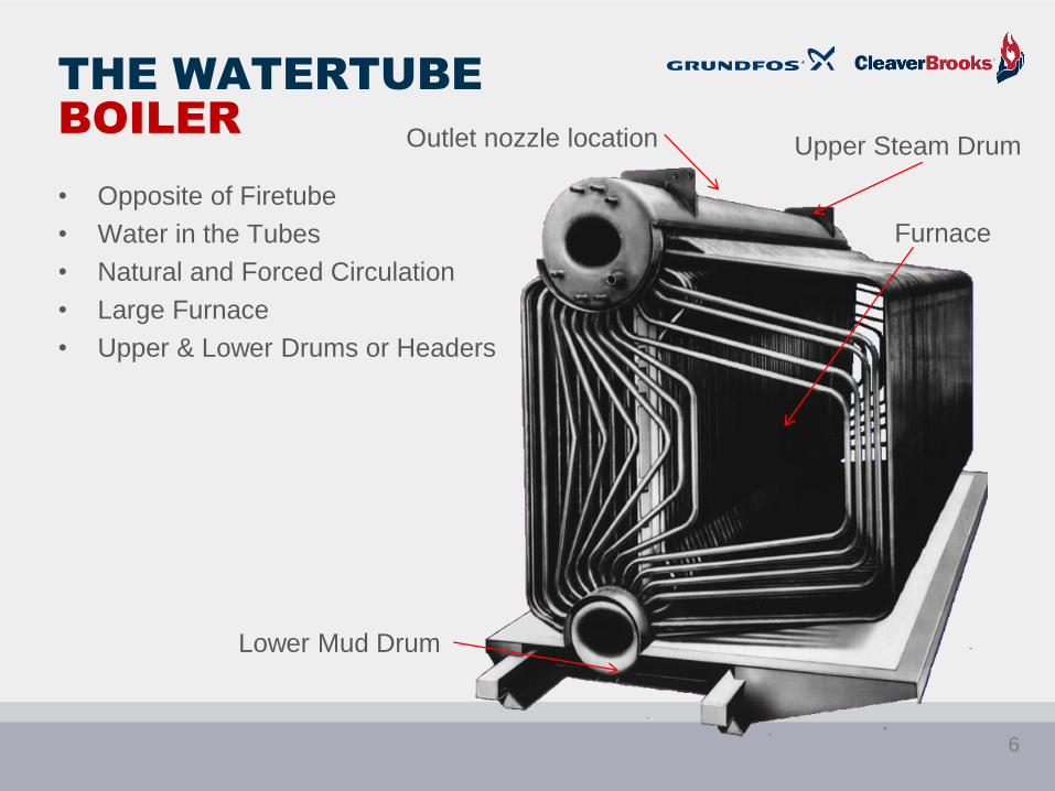
THE WATERTUBE
BOILER
• Opposite of Firetube
• Water in the Tubes
• Natural and Forced Circulation
• Large Furnace
• Upper & Lower Drums or Headers
Upper Steam Drum
Lower Mud Drum
Furnace
Outlet nozzle location
6

STEAM QUALITY
Steam disengaging area
Water level
IWT Upper Steam drum
Steam outlet
7
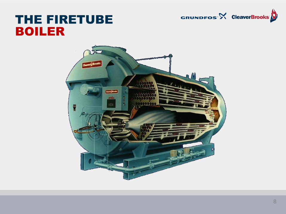
THE FIRETUBE
BOILER
8
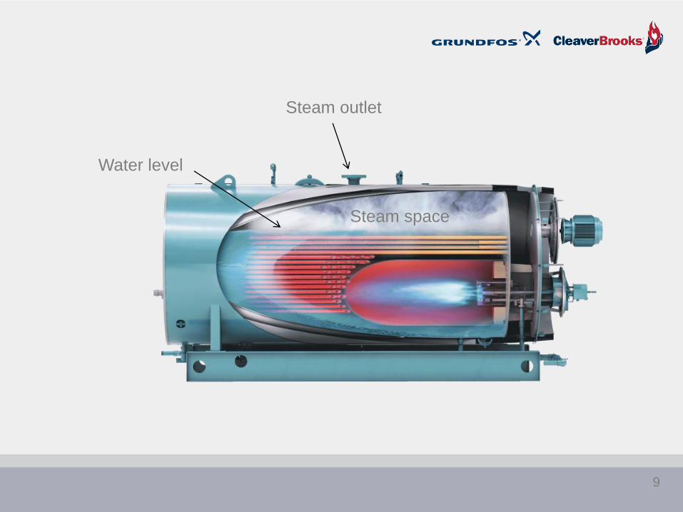
Steam space
Water level
Steam outlet
9
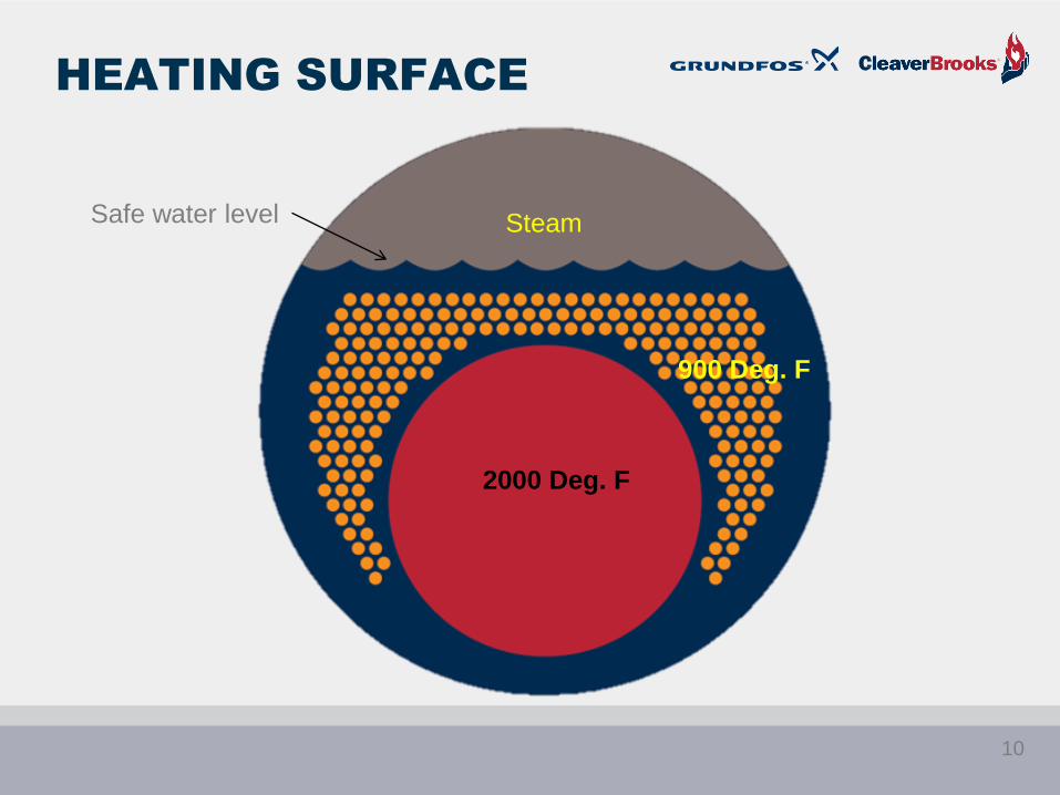
HEATING SURFACE
Safe water level
2000 Deg. F
900 Deg. F
Steam
10


Operating High Limit Modulating
16

TYPICAL
STEAM SYSTEM
T
T
T
T
T
LegendSteamCond
Vapor
H P Cond Return
D A TankD A Tank
Feed PumpBoiler
Strainer
Trap Trap
TrapTT
TT
DA Tank
TT
TT
TTT
Legend
Trap
HP SteamPRV
LP Steam
Trap
LP Condensate Return
Motive
Force
Flash
Modulating Control or Transducer
17
18
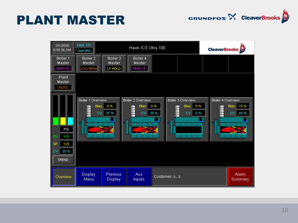
PLANT MASTER
18
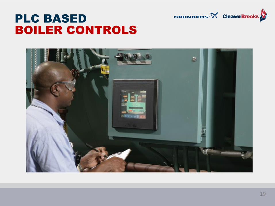
PLC BASED
BOILER CONTROLS
19
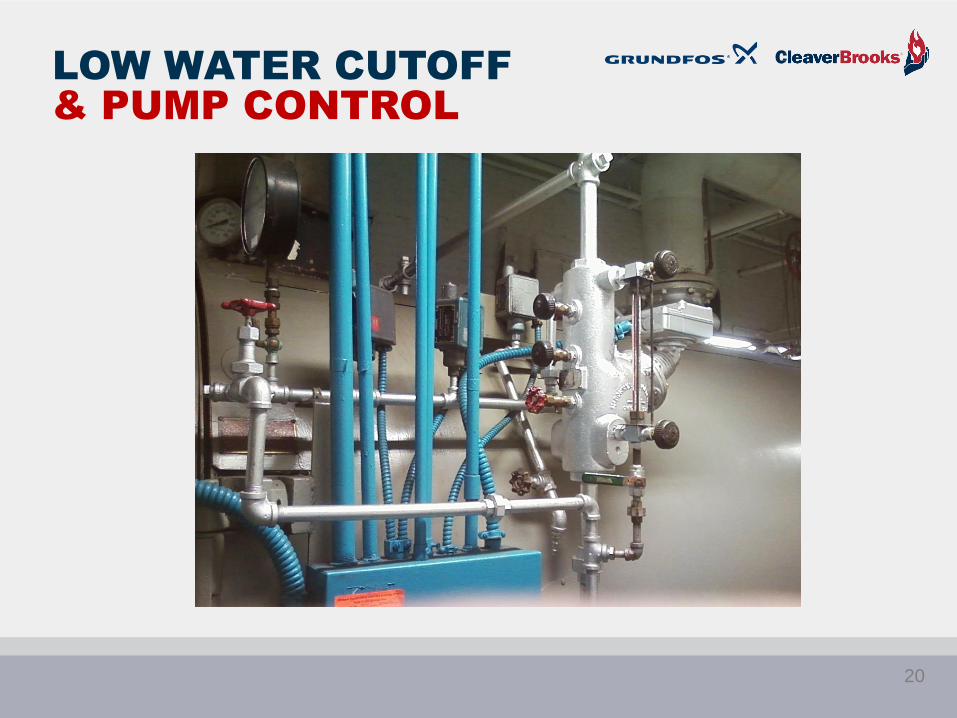
LOW WATER CUTOFF
& PUMP CONTROL
20

Bowl
Float
Armature
Switching head
LOW WATER CUTOFF
& PUMP CONTROL
21

Pump switch
LWCO Switch
22

At 0”= 2”
Section I, High pressure boilers
is first visible point in GG = 2”
above tubes…
23
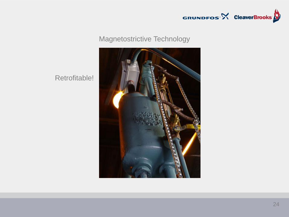
Magnetostrictive Technology
Retrofitable!
24
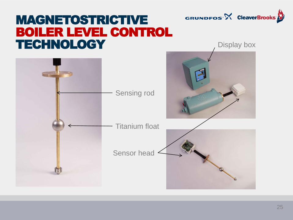
MAGNETOSTRICTIVE
BOILER LEVEL CONTROL
TECHNOLOGY
Sensing rod
Titanium float
Sensor head
Display box
25
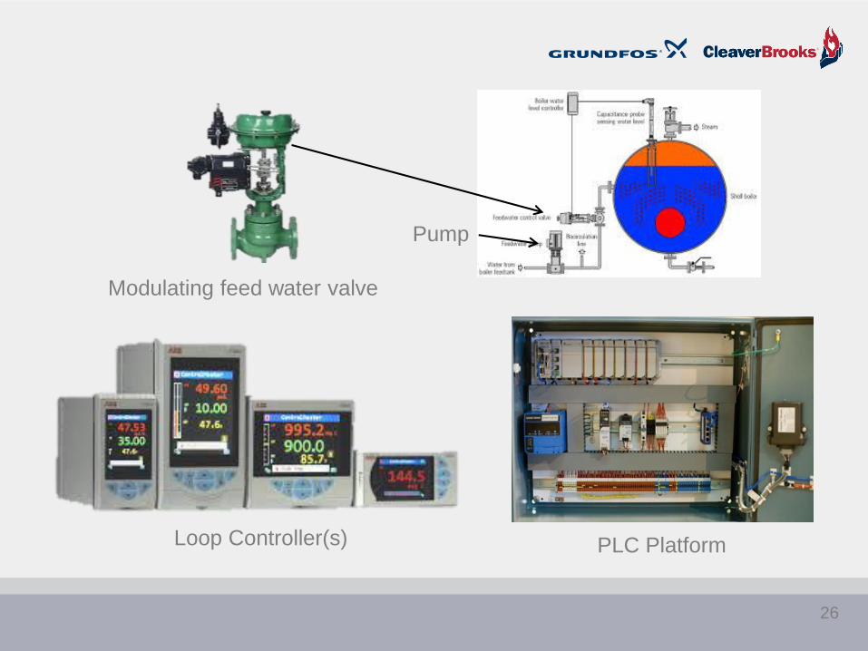
PLC Platform
Modulating feed water valve
Pump
Loop Controller(s)
26

VFD Controller
Magnetostrictive level control
27
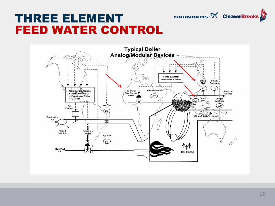
THREE ELEMENT
FEED WATER CONTROL
28
29
BOILER FEED PUMP
CONTROL METHODS
1. On/Off control and fixed speed pumps
2. Feed control valve and fixed speed pumps
3. Feed control valve and variable speed pumps
4. Variable speed pumps only (no control valve)
Method# Name
30
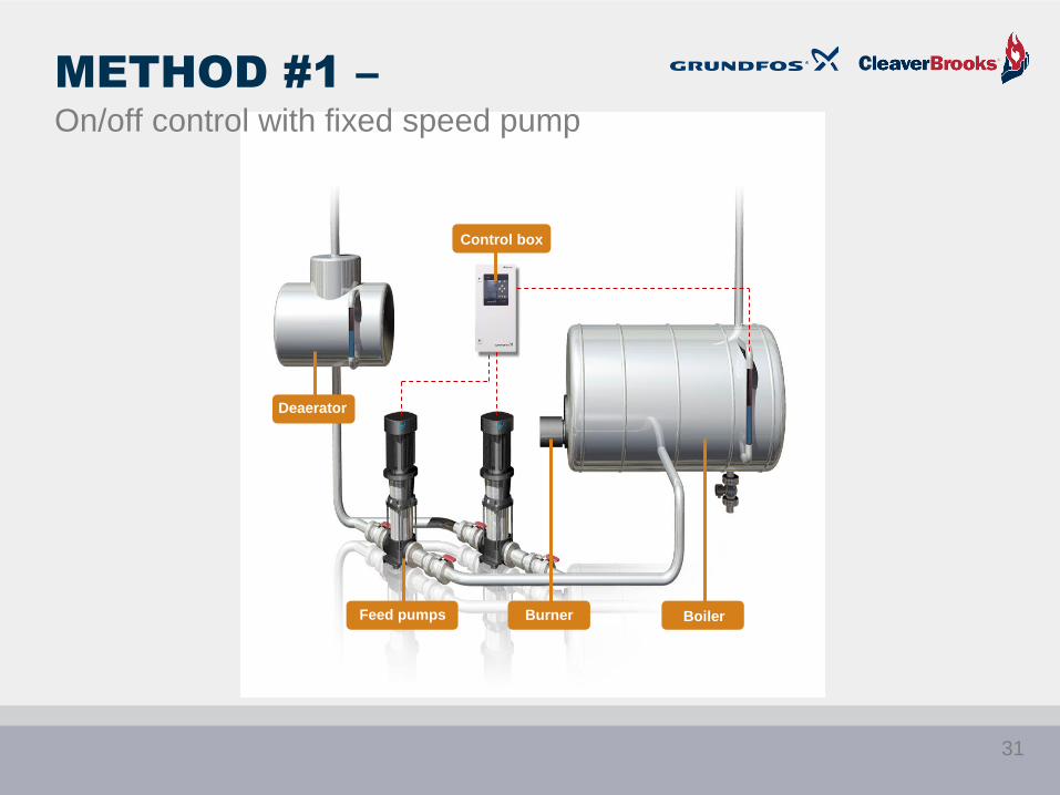
Deaerator
Feed pumps Burner Boiler
Control box
METHOD #1 –
On/off control with fixed speed pump
31
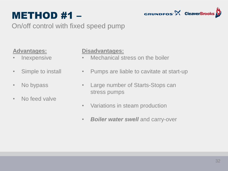
Advantages:
• Inexpensive
• Simple to install
• No bypass
• No feed valve
Disadvantages:
• Mechanical stress on the boiler
• Pumps are liable to cavitate at start-up
• Large number of Starts-Stops can
stress pumps
• Variations in steam production
• Boiler water swell and carry-over
METHOD #1 –
On/off control with fixed speed pump
32

Deaerator
Feed pumps Burner
Boiler
Bypass
Feed valve
METHOD #2 –
Feed valve with fixed speed pumps
33
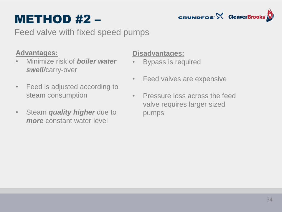
Advantages:
• Minimize risk of boiler water
swell/carry-over
• Feed is adjusted according to
steam consumption
• Steam quality higher due to
more constant water level
Disadvantages:
• Bypass is required
• Feed valves are expensive
• Pressure loss across the feed
valve requires larger sized
pumps
METHOD #2 –
Feed valve with fixed speed pumps
34

Deaerator
Feed pumps
Boiler
Recirculation line
Feed valve
Transducer
METHOD #3 –
Feed valve with variable speed pumps with recirculation line
Level Sensor
35
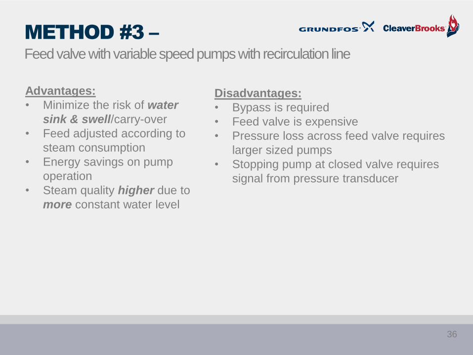
Advantages:
• Minimize the risk of water
sink & swell/carry-over
• Feed adjusted according to
steam consumption
• Energy savings on pump
operation
• Steam quality higher due to
more constant water level
Disadvantages:
• Bypass is required
• Feed valve is expensive
• Pressure loss across feed valve requires
larger sized pumps
• Stopping pump at closed valve requires
signal from pressure transducer
METHOD #3 –
Feed valve with variable speed pumps with recirculation line
36
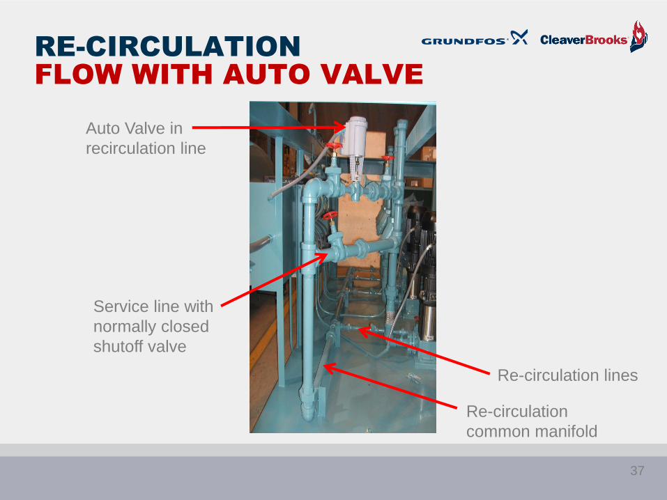
RE-CIRCULATION
FLOW WITH AUTO VALVE
Re-circulation
common manifold
Re-circulation lines
Auto Valve in
recirculation line
Service line with
normally closed
shutoff valve
37

Deaerator
Feed pumps
Boiler
Sensor
METHOD #4 –
Variable speed pumps less feed valve
38
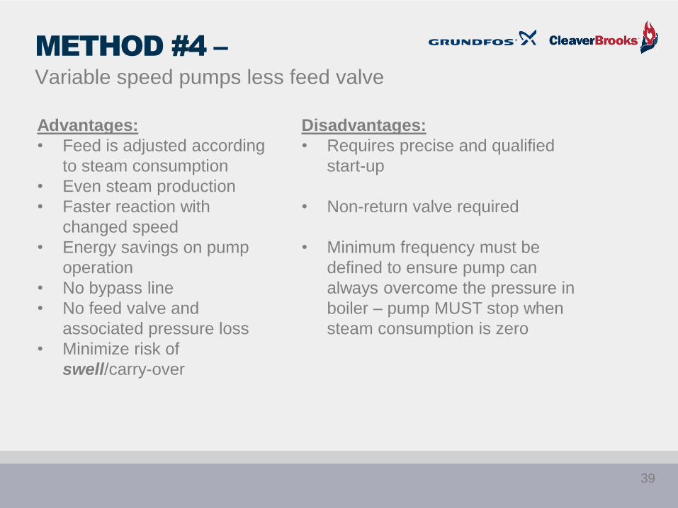
Advantages:
• Feed is adjusted according
to steam consumption
• Even steam production
• Faster reaction with
changed speed
• Energy savings on pump
operation
• No bypass line
• No feed valve and
associated pressure loss
• Minimize risk of
swell/carry-over
Disadvantages:
• Requires precise and qualified
start-up
• Non-return valve required
• Minimum frequency must be
defined to ensure pump can
always overcome the pressure in
boiler – pump MUST stop when
steam consumption is zero
METHOD #4 –
Variable speed pumps less feed valve
39
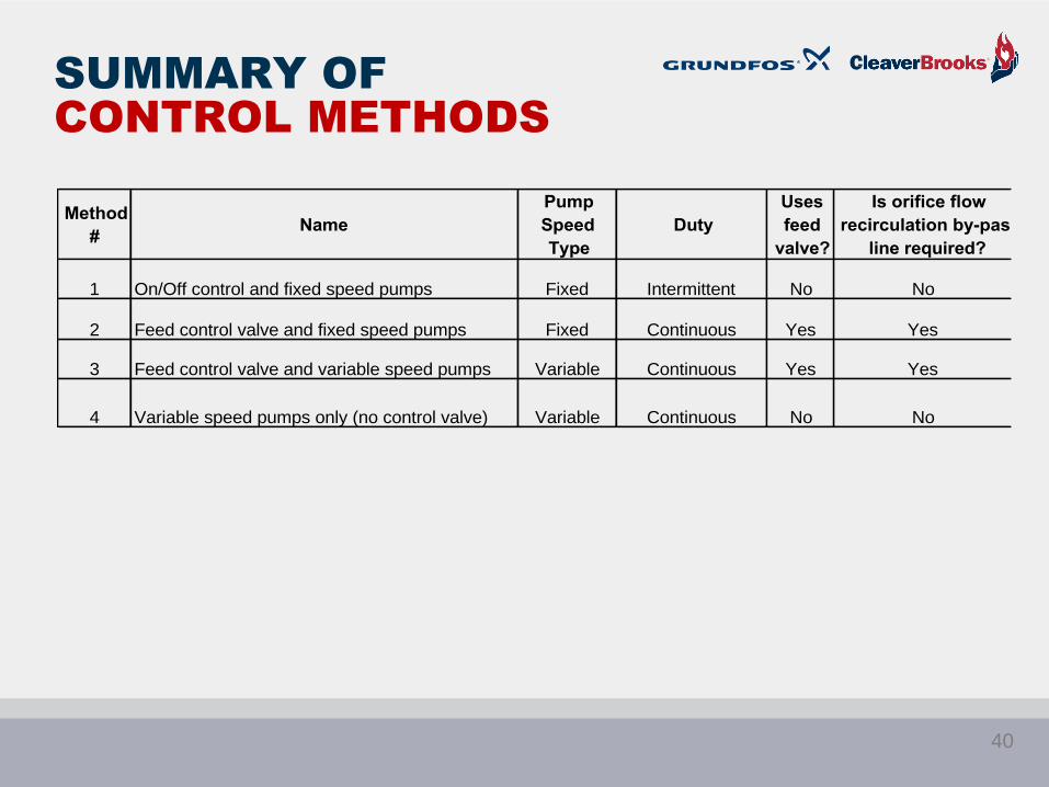
SUMMARY OF
CONTROL METHODS
Method
#Name
Pump
Speed
Type
Duty
Uses
feed
valve?
Is orifice flow
recirculation by-pass
line required?
1 On/Off control and fixed speed pumps Fixed Intermittent No No
2 Feed control valve and fixed speed pumps Fixed Continuous Yes Yes
3 Feed control valve and variable speed pumps Variable Continuous Yes Yes
4 Variable speed pumps only (no control valve) Variable Continuous No No
40
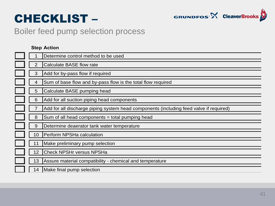
CHECKLIST –
Boiler feed pump selection process
Step Action
1 Determine control method to be used
2 Calculate BASE flow rate
3 Add for by-pass flow if required
4 Sum of base flow and by-pass flow is the total flow required
5 Calculate BASE pumping head
6 Add for all suction piping head components
7 Add for all discharge piping system head components (including feed valve if required)
8 Sum of all head components = total pumping head
9 Determine deaerator tank water temperature
10 Perform NPSHa calculation
11 Make preliminary pump selection
12 Check NPSHr versus NPSHa
13 Assure material compatibility - chemical and temperature
14 Make final pump selection
41

BOILER FEED PUMPS:
USEFUL FORMULAS
1. Base flow calculation equation
Boiler maximum capacity horsepower X 0.069 X C = Base flow rate
C = 1.50 for On/Off intermittent operation
C = 1.15 for continuous feed operation
2. Determine BASE head for feed pump
Formula based on Safety Valve setting:
Pump head in feet = Maximum pressure X 2.31 X 1.03 ÷ Liquid Specific Gravity
3. Head components on suction side of piping system
Pressure above atmospheric on deaerator converted to feet of head = feet
Elevation difference between minimum deaerator water level and pump inlet = feet
Suction pipe friction loss = feet
Suction fitting friction loss = feet
Suction line valves and strainer friction loss = feet
Total = feet
4. Head components on discharge side of piping system
Friction loss through discharge piping = feet
Friction loss through discharge fittings = feet
Friction loss through feed valve = feet
Elevation of boiler maximum water level above pump = feet
Total = feet
5. NPSHa equation
± Elevation** + Absolute pressure – Vapor Pressure – Suction Line Friction = NPSHa
(Feet) (psi X 2.31 = Feet) (psi X 2.31 = Feet) (Feet) (Feet)
** Elevation of deaerator tank minimum water level above pump’s first impeller
42
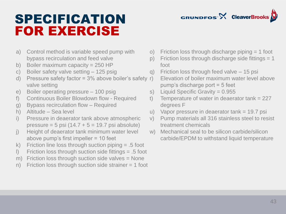
SPECIFICATION
FOR EXERCISE
a) Control method is variable speed pump with
bypass recirculation and feed valve
b) Boiler maximum capacity = 250 HP
c) Boiler safety valve setting – 125 psig
d) Pressure safety factor = 3% above boiler’s safety
valve setting
e) Boiler operating pressure – 100 psig
f) Continuous Boiler Blowdown flow - Required
g) Bypass recirculation flow – Required
h) Altitude – Sea level
i) Pressure in deaerator tank above atmospheric
pressure = 5 psi (14.7 + 5 = 19.7 psi absolute)
j) Height of deaerator tank minimum water level
above pump’s first impeller = 10 feet
k) Friction line loss through suction piping = .5 foot
l) Friction loss through suction side fittings = .5 foot
m) Friction loss through suction side valves = None
n) Friction loss through suction side strainer = 1 foot
o) Friction loss through discharge piping = 1 foot
p) Friction loss through discharge side fittings = 1
foot
q) Friction loss through feed valve – 15 psi
r) Elevation of boiler maximum water level above
pump’s discharge port = 5 feet
s) Liquid Specific Gravity = 0.955
t) Temperature of water in deaerator tank = 227
degrees F
u) Vapor pressure in deaerator tank = 19.7 psi
v) Pump materials all 316 stainless steel to resist
treatment chemicals
w) Mechanical seal to be silicon carbide/silicon
carbide/EPDM to withstand liquid temperature
43
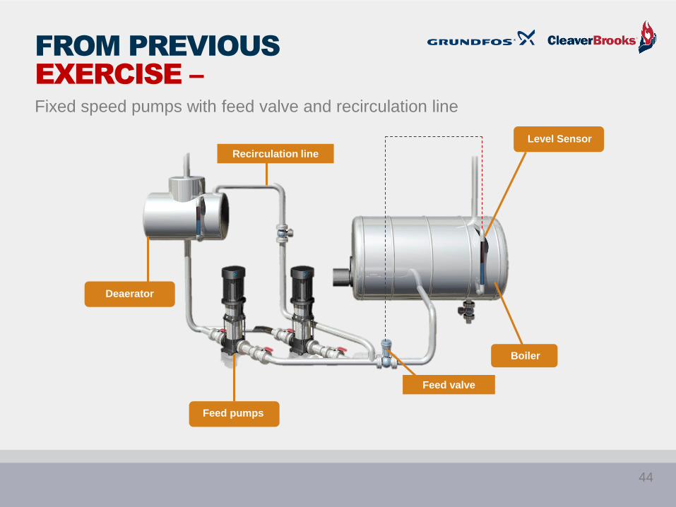
FROM PREVIOUS
EXERCISE –
Fixed speed pumps with feed valve and recirculation line
Recirculation line
Feed valve
Boiler
Level Sensor
Feed pumps
Deaerator
44
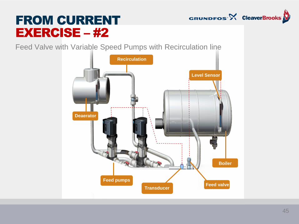
Deaerator
Boiler
Recirculation
line
Feed valveFeed pumps
Transducer
Level Sensor
FROM CURRENT
EXERCISE – #2
Feed Valve with Variable Speed Pumps with Recirculation line
45

STEP 13 –
Preliminary pump selection
• Conditions of
Service:
• Flow = 28 gpm
• Head = 272 feet
Does this 11
stage pump
pump meet the
required flow
and head
conditions of
service?
YES
46
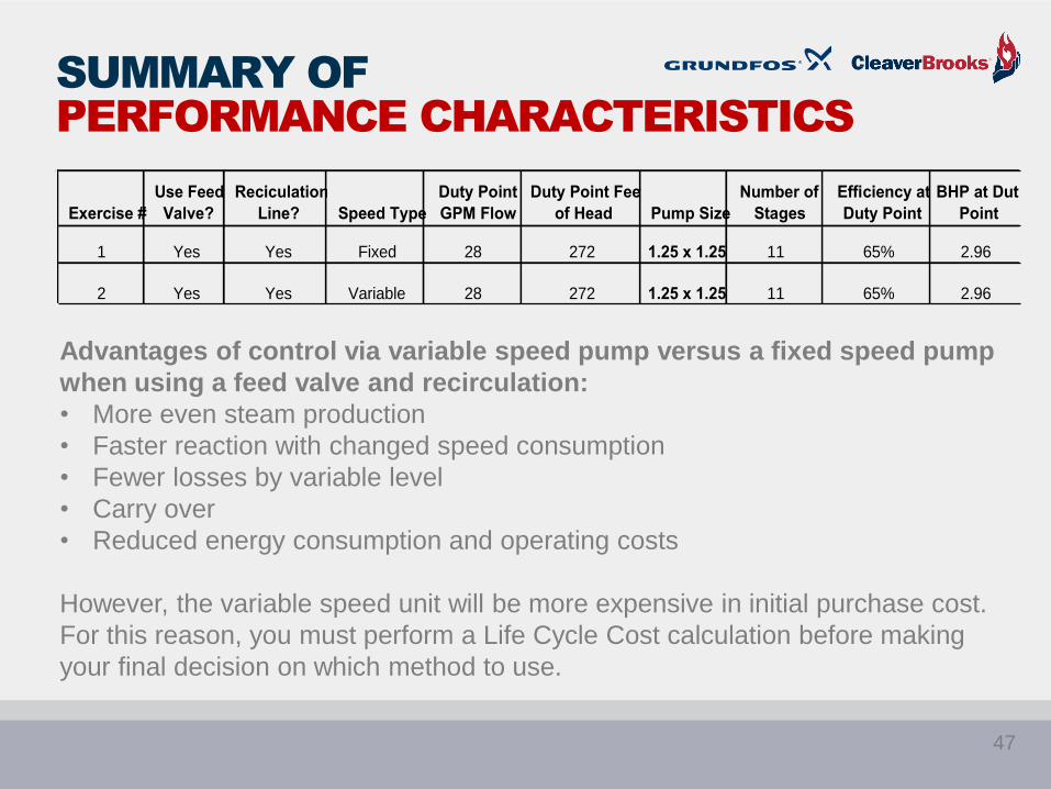
SUMMARY OF
PERFORMANCE CHARACTERISTICS
Advantages of control via variable speed pump versus a fixed speed pump
when using a feed valve and recirculation:
• More even steam production
• Faster reaction with changed speed consumption
• Fewer losses by variable level
• Carry over
• Reduced energy consumption and operating costs
However, the variable speed unit will be more expensive in initial purchase cost.
For this reason, you must perform a Life Cycle Cost calculation before making
your final decision on which method to use.
Exercise #
Use Feed
Valve?
Reciculation
Line? Speed Type
Duty Point
GPM Flow
Duty Point Feet
of Head Pump Size
Number of
Stages
Efficiency at
Duty Point
BHP at Duty
Point
1 Yes Yes Fixed 28 272 1.25 x 1.25 11 65% 2.96
2 Yes Yes Variable 28 272 1.25 x 1.25 11 65% 2.96
47

CURVE COMPARISON –
FIXED SPEED VS VARIABLE
SPEED
Duty point
operation at
3550 rpm
48
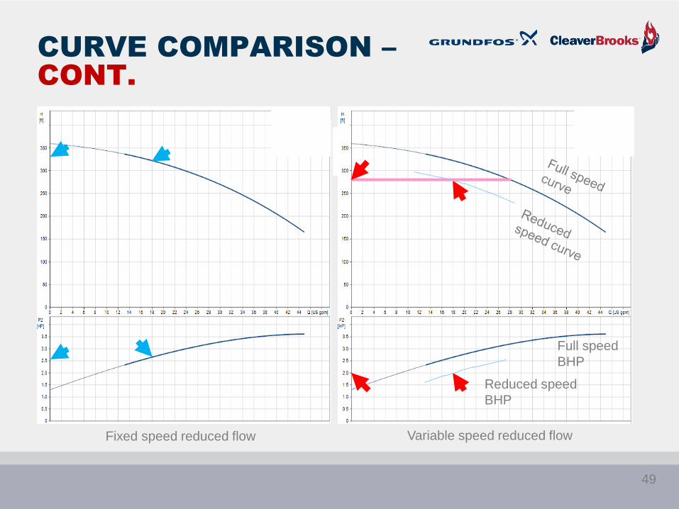
CURVE COMPARISON –
CONT.
Fixed speed reduced flow Variable speed reduced flow
Full speed
BHP
Reduced speed
BHP
49
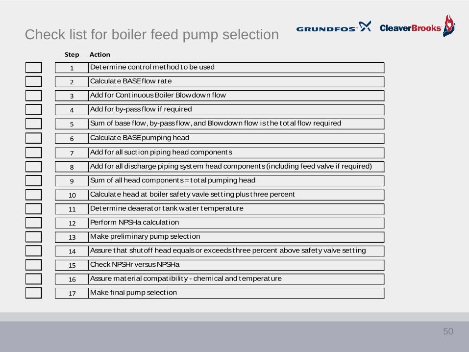
Check list for boiler feed pump selection
Step Action
1 Determine cont rol method to be used
2 Calculate BASE flow rate
3 Add for Cont inuous Boiler Blowdown flow
4 Add for by-pass flow if required
5 Sum of base flow, by-pass flow, and Blowdown flow is the total flow required
6 Calculate BASE pumping head
7 Add for all suct ion piping head components
8 Add for all discharge piping system head components (including feed valve if required)
9 Sum of all head components = total pumping head
10 Calculate head at boiler safety vavle set t ing plus three percent
11 Determine deaerator tank water temperature
12 Perform NPSHa calculat ion
13 Make preliminary pump select ion
14 Assure that shutoff head equals or exceeds three percent above safety valve set t ing
15 Check NPSHr versus NPSHa
16 Assure material compat ibilit y - chemical and temperature
17 Make final pump select ion
50

BOILER FEED PUMPS:
USEFUL FORMULAS
1.Baseflowcalculationequation
BoilermaximumcapacityhorsepowerX0.069XC=Baseflowrate
C=1.50forOn/Offintermittentoperation
C=1.15forcontinuousfeedoperation
2.DetermineBASEheadforfeedpump
FormulabasedonSafetyValvesetting:
Pumpheadinfeet=MaximumpressureX2.31X1.03÷LiquidSpecificGravity
3.Headcomponentsonsuctionsideofpipingsystem
Pressureaboveatmosphericondeaeratorconvertedtofeetofhead= feet
Elevationdifferencebetweenminimumdeaeratorwaterlevelandpumpinlet= feet
Suctionpipefrictionloss= feet
Suctionfittingfrictionloss= feet
Suctionlinevalvesandstrainerfrictionloss= feet
Total= feet
4.Headcomponentsondischargesideofpipingsystem
Frictionlossthroughdischargepiping= feet
Frictionlossthroughdischargefittings= feet
Frictionlossthroughfeedvalve= feet
Elevationofboilermaximumwaterlevelabovepump= feet
Total= feet
5.NPSHaequation
±Elevation**+Absolutepressure–VaporPressure–SuctionLineFriction=NPSHa
(Feet)(psiX2.31=Feet)(psiX2.31=Feet)(Feet)(Feet)
**Elevationofdeaeratortankminimumwaterlevelabovepump’sfirstimpeller
51

SPECIFICATION
FOR EXERCISE
a) Control Method: Continuous duty variable speed pump (feed valve and recirculation line are not required)
b) Boiler maximum capacity = 250 HP
c) Boiler safety valve setting = 115 psig
d) Pressure safety factor = 3% above boiler’s safety valve setting
e) Boiler operating pressure = 100 psig
f) Continuous Boiler Blowdown flow - Required
g) Bypass recirculation flow – Not required
h) Altitude – Sea level
i) Pressure in deaerator tank above atmospheric pressure = 5 psi (14.7 + 5 = 19.7 psi absolute)
j) Height of deaerator tank minimum water level above pump’s first impeller = 10 feet
k) Friction line loss through suction piping = .5 foot
l) Friction loss through suction side fittings = .5 foot
m) Friction loss through suction side valves = None
n) Friction loss through suction side strainer = 1 feet
o) Friction loss through discharge piping = 1 foot
p) Friction loss through discharge side fittings = 1 foot
q) Pressure drop across feed valve – None – Feed valve is not required
r) Elevation of boiler maximum water level above pump’s discharge port = 5 feet
s) Liquid Specific Gravity = 0.953
t) Temperature of water in deaerator tank = 227 degrees F
u) Vapor pressure in deaerator tank = 19.7 psi
v) Pump materials all 316 stainless steel to resist treatment chemicals
w) Mechanical seal to be silicon carbide/silicon carbide/EPDM to withstand liquid temperature
52
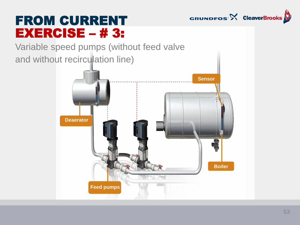
Deaerator
Feed pumps
Boiler
Sensor
FROM CURRENT
EXERCISE – # 3:
Variable speed pumps (without feed valve
and without recirculation line)
53

STEP 1 –
• Determine control method
• A variable speed pump has been specified. Specification excludes feed
valve and recirculation line
X
Step Action
1 Determine cont rol method to be used
2 Calculate BASE flow rate
3 Add for Cont inuous Boiler Blowdown flow
4 Add for by-pass flow if required
5 Sum of base flow, by-pass flow, and Blowdown flow is the total flow required
6 Calculate BASE pumping head
7 Add for all suct ion piping head components
8 Add for all discharge piping system head components (including feed valve if required)
9 Sum of all head components = total pumping head
10 Calculate head at boiler safety vavle set t ing plus three percent
11 Determine deaerator tank water temperature
12 Perform NPSHa calculat ion
13 Make preliminary pump select ion
14 Assure that shutoff head equals or exceeds three percent above safety valve set t ing
15 Check NPSHr versus NPSHa
16 Assure material compat ibilit y - chemical and temperature
17 Make final pump select ion
54
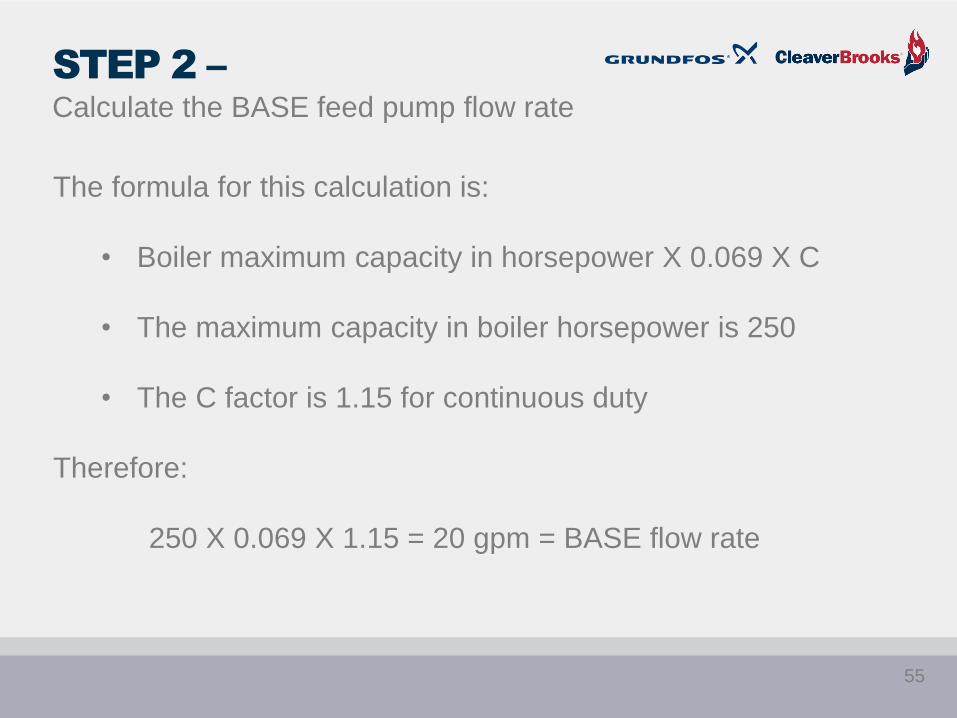
STEP 2 –
Calculate the BASE feed pump flow rate
The formula for this calculation is:
• Boiler maximum capacity in horsepower X 0.069 X C
• The maximum capacity in boiler horsepower is 250
• The C factor is 1.15 for continuous duty
Therefore:
250 X 0.069 X 1.15 = 20 gpm = BASE flow rate
55
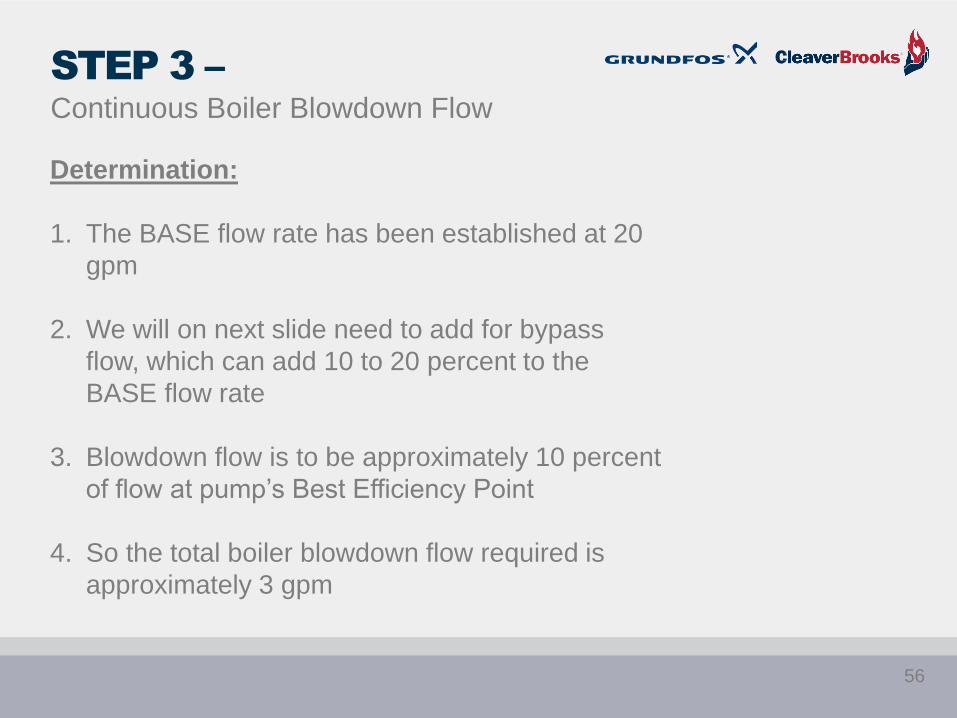
STEP 3 –
Continuous Boiler Blowdown Flow
Determination:
1. The BASE flow rate has been established at 20
gpm
2. We will on next slide need to add for bypass
flow, which can add 10 to 20 percent to the
BASE flow rate
3. Blowdown flow is to be approximately 10 percent
of flow at pump’s Best Efficiency Point
4. So the total boiler blowdown flow required is
approximately 3 gpm
56

STEP 4 –
Recirculation by-pass flow
Not required per the specification
57
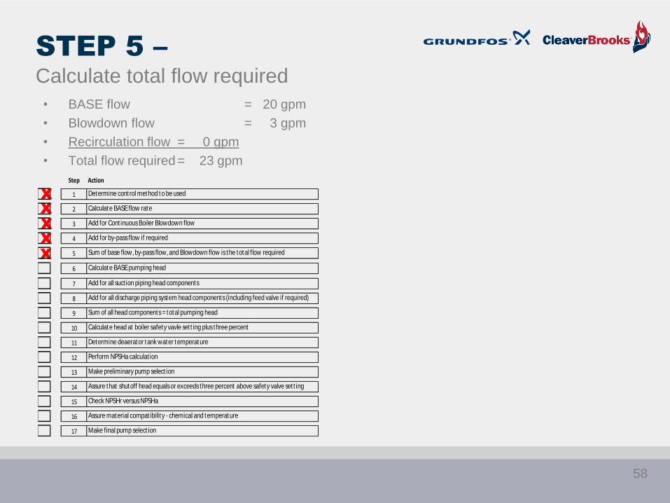
STEP 5 –
Calculate total flow required
• BASE flow = 20 gpm
• Blowdown flow = 3 gpm
• Recirculation flow = 0 gpm
• Total flow required= 23 gpm
X
X
X
X
X
Step Action
1 Determine cont rol method to be used
2 Calculate BASE flow rate
3 Add for Cont inuous Boiler Blowdown flow
4 Add for by-pass flow if required
5 Sum of base flow, by-pass flow, and Blowdown flow is the total flow required
6 Calculate BASE pumping head
7 Add for all suct ion piping head components
8 Add for all discharge piping system head components (including feed valve if required)
9 Sum of all head components = total pumping head
10 Calculate head at boiler safety vavle set t ing plus three percent
11 Determine deaerator tank water temperature
12 Perform NPSHa calculat ion
13 Make preliminary pump select ion
14 Assure that shutoff head equals or exceeds three percent above safety valve set t ing
15 Check NPSHr versus NPSHa
16 Assure material compat ibilit y - chemical and temperature
17 Make final pump select ion
58
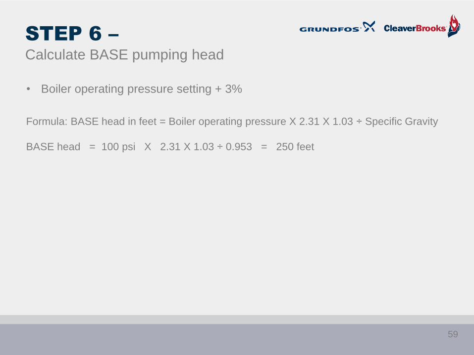
STEP 6 –
Calculate BASE pumping head
• Boiler operating pressure setting + 3%
Formula: BASE head in feet = Boiler operating pressure X 2.31 X 1.03 ÷ Specific Gravity
BASE head = 100 psi X 2.31 X 1.03 ÷ 0.953 = 250 feet
59
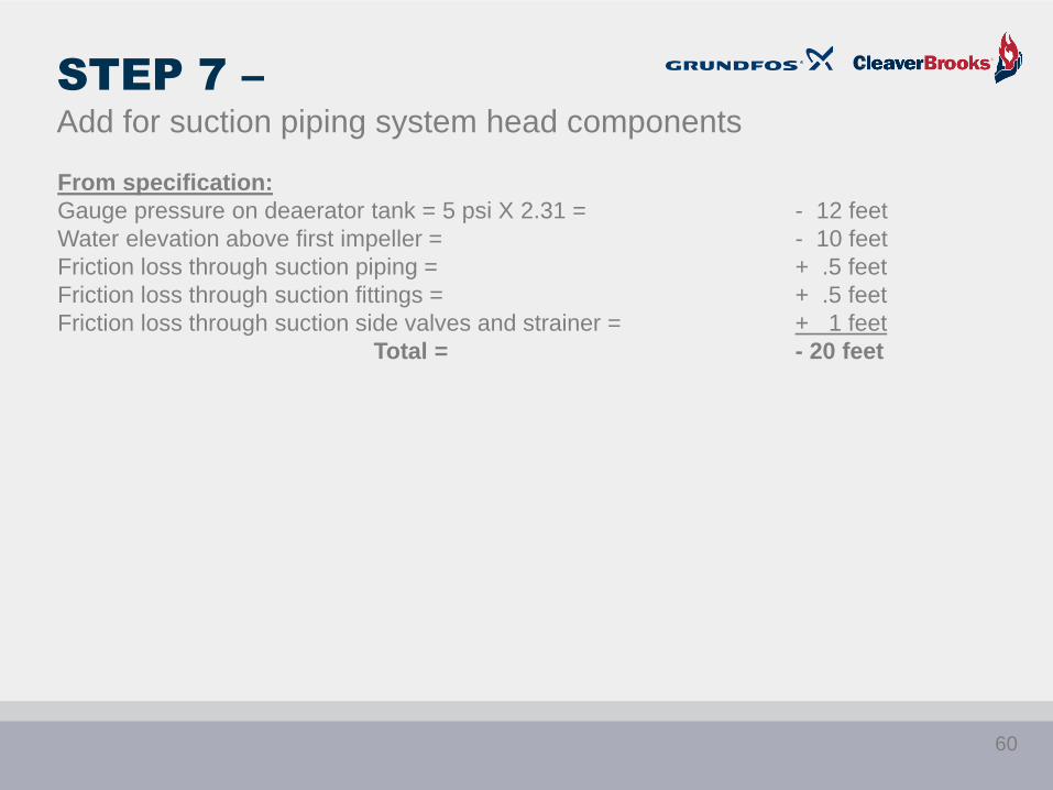
STEP 7 –
Add for suction piping system head components
From specification:
Gauge pressure on deaerator tank = 5 psi X 2.31 = - 12 feet
Water elevation above first impeller = - 10 feet
Friction loss through suction piping = + .5 feet
Friction loss through suction fittings = + .5 feet
Friction loss through suction side valves and strainer = + 1 feet
Total = - 20 feet
60

STEP 8 –
Add for discharge piping system head components
From specification:
Friction loss through discharge piping = + 1 foot
Friction loss through discharge fittings = + 1 foot
Friction loss through feed valve = + 0 feet
Elevation of boiler maximum water level above pump = + 5 feet
Total = + 7 feet
61
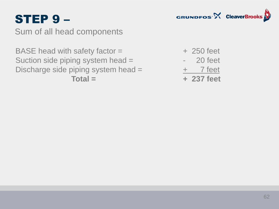
STEP 9 –
Sum of all head components
BASE head with safety factor = + 250 feet
Suction side piping system head = - 20 feet
Discharge side piping system head = + 7 feet
Total = + 237 feet
62

STEP 10 –
Pressure safety valve considerations
At shutoff head (dead head):
Head in feet = Pressure relief valve setting X 2.31 X 1.03 ÷ Liquid Specific Gravity
Example: Head = 115 psi X 2.31 X 1.03 ÷ 0.953 = 287 feet
X
X
X
X
X
X
X
X
X
X
Step Action
1 Determine cont rol method to be used
2 Calculate BASE flow rate
3 Add for Cont inuous Boiler Blowdown flow
4 Add for by-pass flow if required
5 Sum of base flow, by-pass flow, and Blowdown flow is the total flow required
6 Calculate BASE pumping head
7 Add for all suct ion piping head components
8 Add for all discharge piping system head components (including feed valve if required)
9 Sum of all head components = total pumping head
10 Calculate head at boiler safety vavle set t ing plus three percent
11 Determine deaerator tank water temperature
12 Perform NPSHa calculat ion
13 Make preliminary pump select ion
14 Assure that shutoff head equals or exceeds three percent above safety valve set t ing
15 Check NPSHr versus NPSHa
16 Assure material compat ibilit y - chemical and temperature
17 Make final pump select ion
63

STEP 11 –
Determine deaerator tank water temperature
From specification: 227°F
64
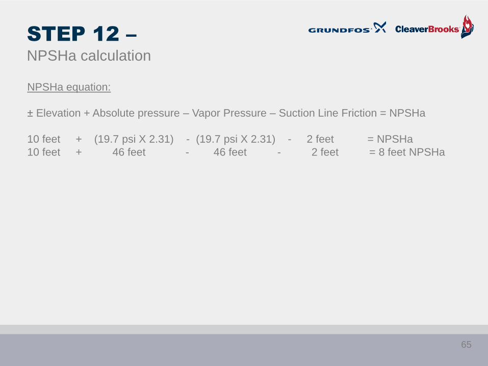
STEP 12 –
NPSHa calculation
NPSHa equation:
± Elevation + Absolute pressure – Vapor Pressure – Suction Line Friction = NPSHa
10 feet + (19.7 psi X 2.31) - (19.7 psi X 2.31) - 2 feet = NPSHa
10 feet + 46 feet - 46 feet - 2 feet = 8 feet NPSHa
65
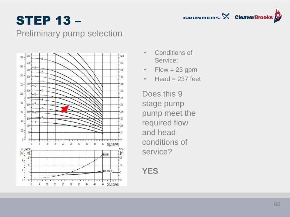
STEP 13 –
Preliminary pump selection
• Conditions of
Service:
• Flow = 23 gpm
• Head = 237 feet
Does this 9
stage pump
pump meet the
required flow
and head
conditions of
service?
YES
66
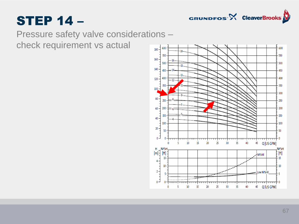
STEP 14 –
Pressure safety valve considerations –
check requirement vs actual
67

STEP 15 –
Check NPSHa vs NPSHr
• Conditions of Service:
• Flow = 23 gpm
• Head = 237 Feet
• NPSHa = 8 Feet
• Pump meets or exceeds
flow/head requirement
• Low-NPSHr first stage = 3.5 feet
required
• NPSHr safety factor = 2 to 4 feet
• Target NPSHr = 7.5 feet
• NPSHa = 8 feet
Does NPSHa equal or exceed NPSHr?
YES
68

STEP 15 –
NPSH - Continued
• Conditions of Service: Flow = 23 gpm Head = 237 feet NPSHa = 8 Feet
• The NPSHa of 8 feet exceeds the NPSHr of 7.5 feet
X
X
X
X
X
X
X
X
X
X
X
X
X
X
X
Step Action
1 Determine cont rol method to be used
2 Calculate BASE flow rate
3 Add for Cont inuous Boiler Blowdown flow
4 Add for by-pass flow if required
5 Sum of base flow, by-pass flow, and Blowdown flow is the total flow required
6 Calculate BASE pumping head
7 Add for all suct ion piping head components
8 Add for all discharge piping system head components (including feed valve if required)
9 Sum of all head components = total pumping head
10 Calculate head at boiler safety vavle set t ing plus three percent
11 Determine deaerator tank water temperature
12 Perform NPSHa calculat ion
13 Make preliminary pump select ion
14 Assure that shutoff head equals or exceeds three percent above safety valve set t ing
15 Check NPSHr versus NPSHa
16 Assure material compat ibilit y - chemical and temperature
17 Make final pump select ion
69
STEP 16 –
Check material compatibility
• Pump materials: 316 stainless steel
• Mechanical seal materials: Silicon carbide/silicon carbide/EPDM
70

STEP 17 –
Final pump selection
• Pump meets all specification requirements
X
X
X
X
X
X
X
X
X
X
X
X
X
X
X
X
X
Step Action
1 Determine cont rol method to be used
2 Calculate BASE flow rate
3 Add for Cont inuous Boiler Blowdown flow
4 Add for by-pass flow if required
5 Sum of base flow, by-pass flow, and Blowdown flow is the total flow required
6 Calculate BASE pumping head
7 Add for all suct ion piping head components
8 Add for all discharge piping system head components (including feed valve if required)
9 Sum of all head components = total pumping head
10 Calculate head at boiler safety vavle set t ing plus three percent
11 Determine deaerator tank water temperature
12 Perform NPSHa calculat ion
13 Make preliminary pump select ion
14 Assure that shutoff head equals or exceeds three percent above safety valve set t ing
15 Check NPSHr versus NPSHa
16 Assure material compat ibilit y - chemical and temperature
17 Make final pump select ion
71

SUMMARY OF
PERFORMANCE CHARACTERISTICS
Exercise
#
Speed
Type
Use
Feed
Valve?
Reciculatio
n Line?
Duty Point
GPM Flow
Duty Point
Feet of
Head
Pump
Size
Number
of Stages
Efficiency at
Duty Point
BHP at
Duty
Point
1 Fixed Yes Yes 28 272 1.25 x 1.25 11 65% 2.96
2 Variable Yes Yes 28 272 1.25 x 1.25 11 65% 2.96
3 Variable No No 23 237 1.25 x 1.25 9 63% 2.18
Advantages of control via variable speed pump without feed valve and without bypass:
• Even steam production
• Faster reaction with changed speed consumption
• Fewer losses by variable level
• Carryover
• Few stages – lower initial cost
• Eliminate feed valve expense, maintenance, and head loss
• Eliminate bypass line expense and wasted flow recirculation
• Reduced energy consumption and costs
• Particularly at reduced speeds, flows, and heads
• Disadvantage: More complex to commission and start up.
72

6
1
GRUNDFOS TECHNICAL
INSTITUTE
www.grundfos.us/training
• Virtual Classroom
- Self-Paced
- Over 40 courses
- Certificates of Completion
• Webinars
- Live and Recorded
• Face-to-Face Training
73
SUMMARY
• The low water cutoff and pump control is the most important safety device on the boiler.
• It controls the safe level of water in the boiler and shuts it down when the level drops to an unsafe
level
• The level control may include a float with switches or other electronic devices providing safe
monitoring and pump, and/or MFWV energizing.
• These electronic level controls can work in conjunction with VFD’s
• Three element feedwater control involves the interrelationship of level, steam flow, and feedwater flow
• With on/off pump control the signal comes from the LWCO and there is no MFWV or by-pass line.
• Continuous running pump strategy with MFWV includes a by-pass to assure proper operation, and it
may add to the size of the pump.
• A continuous running pump with VFD & MFWV also requires a by-pass line to compensate for no or
low flow conditions.
• With this strategy, the signal for the MFWV normally comes from the level control and a separate loop
controller is used for the VFD.
• With the Auto valve in the by-pass line, the re-circ stops when full flow conditions exist, saving pump
energy, and possibly resulting in a smaller pump size..
• .With VFD and no MFWV, the re-circ line is eliminated resulting in a smaller pump selection
• This strategy requires an expert technician for commissioning.
74

Gregg Achtenhagen
Jim Swetye
QUESTIONS?