cb-dsa control board cobra - futureelectronics.com touch screens/cb-dsafs.pdftouch screen control...
TRANSCRIPT
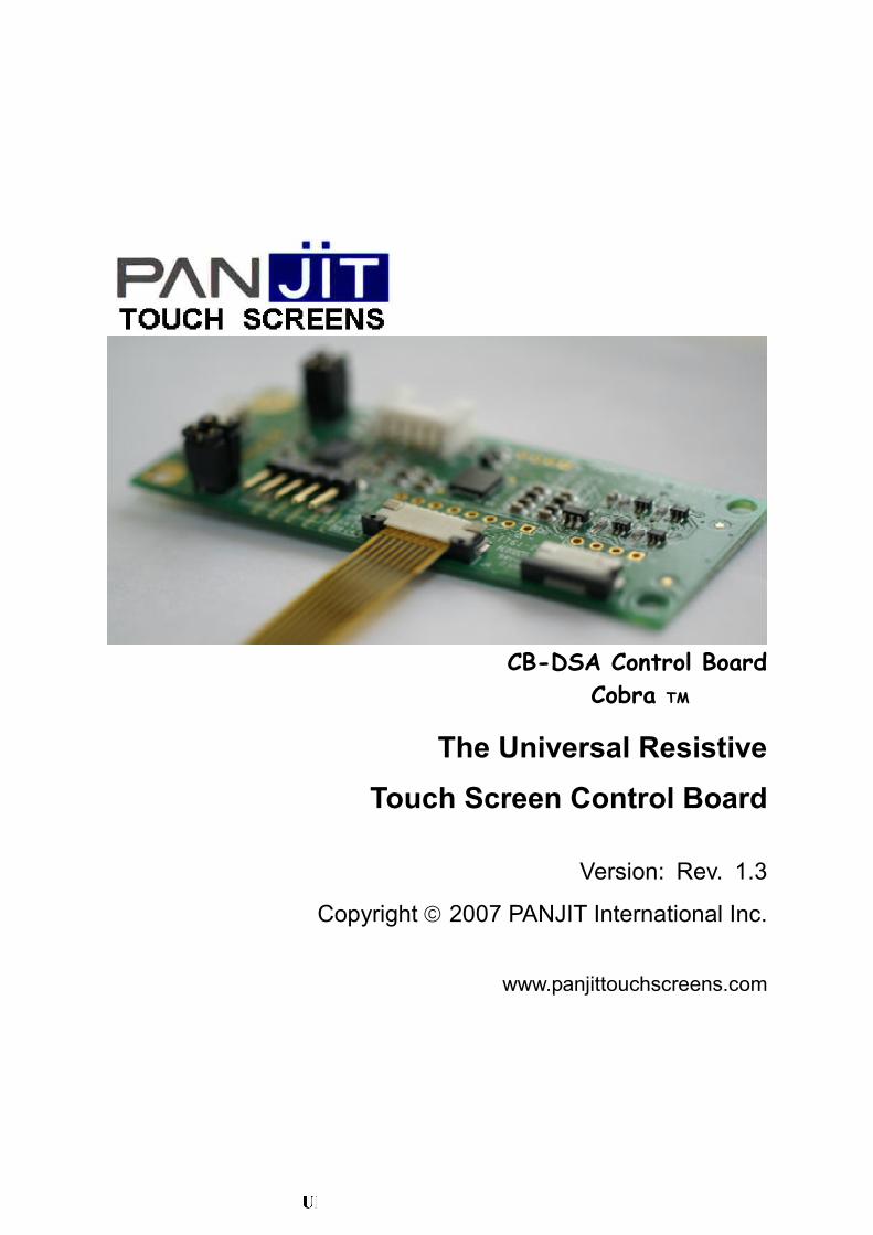
CB-DSA Control Board
Cobra TM
The Universal Resistive
Touch Screen Control Board
Version: Rev. 1.3
Copyright 2007 PANJIT International Inc.
www.panjittouchscreens.com

CB-DSA Touch Screen Control Board
1
Features
Auto detect USB and RS232 interface
Auto detect 4, 5 and 8-wires resistive touch screen
Support Plug an Play (PnP) or non-PnP mode of RS232 interface by firmware options
Support industry highest 4096x4096 resolution
Low power consumption
RoHS-Lead free compliant
Windows OS and Linux customized design
Support 3, 4, 9 and 25 points of calibration and save parameters on board memory
Right click function definition
Double click support
Multi-monitor supported in Windows OS
Support drawing test utility
Auto-detect screen rotation for Intel VGA standard
WHQL approval
Specifications
Touch Screen 4, 5, 8-wires touch screen
Communications Protocol USB / RS232
Resolution 4096 x 4096
Resistance Range Pin to pin above 50 Ω
Operation Voltage +5Vdc ±5% (inner regulator on chip to 3.3V)
Power Consumption
Standby current : 3.5mA
Operating current : typical 10 ~ 16mA depending on touch screen resistance
Operating Temperature -40 ~ 85
Storage Temperature -40 ~ 85
Electro-Static Discharge(ESD) Air : 20kV
Contact : 8kV
Dimensions 75mm x 30mm
Portrait Support 0°, 90°, 180° and 270° screen rotations
Operating Systems DOS (only RS-232)
Windows Series:
Windows VISTA Windows XP/XP Embedded, Windows 2000, Windows 98/ME, Windows CE.net 4.2(X86/ARM)
Linux Series:
Fedora Core I/II, Mandrake 10.0/10.1 RedHat 9.0, SUSE 10.1, …
*See the website for the update information
http://www.panjittouchscreens.com/
Warranty 1 Year

CB-DSA Touch Screen Control Board
2
1. General Description
CB-DSA control board is an all-in-one combo resistive touch screen control board designed for USB/RS232 interfaces, and especially for 4, 5, 8-wires resistive touch screens. Due to the fully auto-detect functions, the touch screen applications could have dual interfaces (USB and RS232) at the same time without any jumper setup. Furthermore, it also automatically detects 4, 5, 8-wires touch screens. It brings flexibility and selective functionality to supply the application varieties of resistive touch screens.
This high performance electronics platform provides 12-bits high resolution, on-chip non-volatile memory to store calibration data and application parameters, and wide operating temperature range. Combined with high performance controller and enhanced software supports, friendly user interfaces and robust calibration algorithm, CB-DSA control board is the most advanced cost-effective touch screen controller available in the market.
CB-DSA Control Board
USB Engine
Flash RS-232 Transceiver
Filter
ADC
4, 5 or 8-Wires Touch Screen
RS232
Interface
USB
Interface
System of CB-DSA Control Board
Voltage Regulator +5V
+3.3V
+3.3V
MCU

CB-DSA Touch Screen Control Board
3
2. Block Diagram
P/N: CBDSAF
4-Wires Pad
8-Wires Pad
4-Wires FPC Connector
5-Wires Connector 8-Wires FPC Connector
5-Wires Jumper
RS232 Connector
Reserve Jumper for Customization USB Connector

CB-DSA Touch Screen Control Board
4
P/N: CBDSAH
8-Wires Connector
4-Wires Connector

CB-DSA Touch Screen Control Board
5
P/N: CBDSAE
4-Wires FPC Connector

CB-DSA Touch Screen Control Board
6
3. Setting up CB-DSA
The CB-DSA control board could fully auto-detect USB or RS-232 interface and 4, 5, or 8-wires touch screen. Thus before powering the system, only one of RS-232 or USB cable and only one of 4, 5 or 8-wires touch screen must be connected to the control board.
NOTE: If plugging RS-232 and USB interface at the same time before powering up, since the priority of RS-232 is higher then USB, only RS-232 interface will work as a result.
The on board reserve jumper is used to switch customize data protocol or PANJIT default data protocol such like data package, communication protocol, commends, …, etc. Those extra function or data protocol could be added in a different firmware. The default firmware neglects the reserve jumper.
3.1 Serial Interface
CB-DSA control board can be connected to personal computer or other serial type device. One RS232 transceiver is used to converter the voltage level between the micro controller and COM port, shown in Figure (1). The logical level
is inversed between J9 and MCU. Figure (2) shows the connection between COM port and CB-DSA.
Figure (1) RS232 transceiver
Figure (2) J9 and COM port connection
J9 pin assignment
PIN 1 VCC 5V Power Supply Voltage Input.
PIN 2 TxD Transmit Data
PIN 3 RxD Received Data
PIN 4 RTS Request To Send
PIN 5 GND Ground.

CB-DSA Touch Screen Control Board
7
The connection of using RS232 interface is shown in Figure (3). The PS/2 plug and jack are used to connect the PS/2 port on motherboard for power supply and to mouse or keyboard for spare use, respectively. If in PnP mode, the DTR pin should be echoed to DSR pin in the D-sub connecter. If in non-PnP mode, the DTR pin and DSR pin are neglected.
In PnP mode, before booting up the operation system, the touch screen controller should be connected to PC and powered up. Because during the boot up procedure, the operation system will conduct hardware scan to check which peripheral devices are workable. After enumeration procedure, the touch driver will be loaded and start running. This should be noted especially in applications, which the power source is from monitor or other source different with the system. If the touch controller is powered up after the operation system booting procedure, hardware re-scan should be executed to load the touch driver. The touch screen driver is shown as a serial mouse class device. The advantage of PnP mode is if the touch controller is not used, the COM port resource will be released without uninstalling the touch driver.
In non-PnP mode, after installing the non-PnP touch driver, the driver will always be loaded after the driver enumeration of the operation system. Thus, if powering up the touch controller after booting up the operation system, the touch screen still works. The disadvantage is if the touch controller is not used, the COM port resource will
not be released unless uninstalling the touch driver. It is possible to use non-PnP driver with PnP controller by installing non-PnP driver first. The result is in non-PnP mode.
The serial communication protocol is shown as following:
(1) Transfer rate: 9600bps
(2) Data transmission mode: Asynchronous
(3) Bit format: 1 start bit, 8 data bits, 1 stop bit, No parity bit, LSB first
_____ __________________________________________ IDLE | START | D0 | D1 | D2 | D3 | D4 | D5 | D6 | D7 | STOP IDLE
3.2 USB Interface
Users can use J3 of DSA control board to connect USB host (PC) as shown in Figure (4). The USB cable has five lines, which are VBUS, GND, D+, D- and drain wire. The VBUS accommodate DC 5V voltage and less then 100mA current. The D+ and D- signal lines control the data between DSA control board and the host. The drain wire connects to ground in DSA control board.
The default firmware of CB-DSA for USB interface is of HID mouse class. The touch driver must be installed to replace the HID mouse driver to conduct the calibration and other parameters setting. In Windows XP tablet edition and Windows Vista operation system, it is possible to
J3 pin assignment
PIN 1 GND Drain wire
PIN 2 VBUS 5V Power Supply From Host
PIN 3 GND Ground
PIN 4 D+ D+ Signal
PIN 5 D- D- Signal

CB-DSA Touch Screen Control Board
8
use the inbox driver for touch device. The firmware would be changed to HID digitizer. Thus the touch device can use the standard driver and functions of these two operation systems.
4. Touch Screens
Normally, the resistive touch screen consists of two conductive layers. The top layer is ITO film while the bottom layer can be either ITO film or ITO glass. One of these two layers is suspended by very small spacer dots to separate these two layers. When the operator touches the touch screen, the conductive inner surface of the ITO film makes contact with the conductive coating on the top surface of the ITO film or ITO glass. Then, the controller senses the touch and passes the information to the corresponded system.
CB-DSA supports three major types of resistive touch screens, including 4-wires, 5-wires and 8-wires touch screens. Each type has different considerations. 4-wires touch screen is the preferred solution for low cost applications. 5-wires is for applications requiring durability and reliability over time. And 8-wires is the preferred solution for applications requiring accuracy and no re-calibration over time.
4.1 4-Wires Touch Screen
About 4-wires touch screen interface, J2 (FPC connector) and J1 (Housing connector) have the same pinout definition as shown in Table (1). However, due to the powerful calibration algorithm of PANJIT, the X and Y directions could be exchanged. And in each direction, the direction can also be inversed, i.e. X+ pin and X- pin can be exchanged and the same as Y+ and Y-. Thus, as only as XYXY type pinout of 4-wires touch screens can be directly connected to CB-DSA. Figure (5) shows some examples of XYXY type layouts of 4-wires touch screens. If the pinout is XXYY type as shown in Figure (6), one intermediate cable is necessary to crossover the pin2 and pin3.
Table (1) The pinout of 4-wires touch screen
Pin1 Y-
Pin2 X-
Pin3 Y+
Pin4 X+
Figure (5) Some layout examples of XYXY type 4-wires touch screens
Figure (6) Some layout examples of XXYY type 4-wires touch screens
CB-DSA Touch Screen Control Board
9
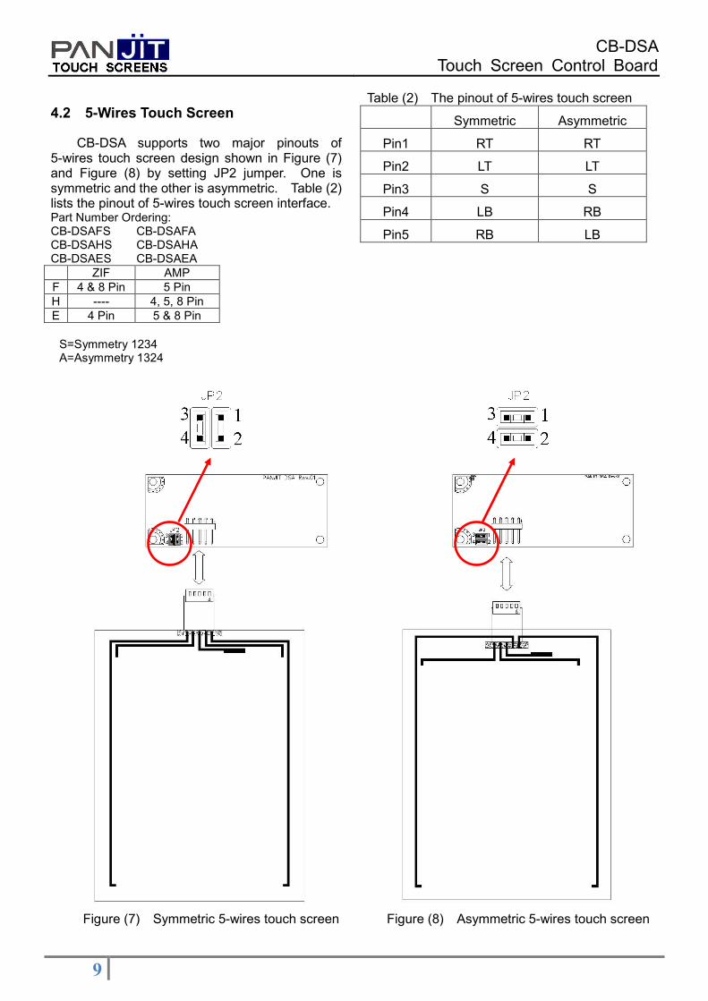
4.2 5-Wires Touch Screen
CB-DSA supports two major pinouts of 5-wires touch screen design shown in Figure (7) and Figure (8) by setting JP2 jumper. One is symmetric and the other is asymmetric. Table (2) lists the pinout of 5-wires touch screen interface. Part Number Ordering: CB-DSAFS CB-DSAFA CB-DSAHS CB-DSAHA CB-DSAES CB-DSAEA
ZIF AMP
F 4 & 8 Pin 5 Pin
H ---- 4, 5, 8 Pin
E 4 Pin 5 & 8 Pin
Table (2) The pinout of 5-wires touch screen
Symmetric Asymmetric
Pin1 RT RT
Pin2 LT LT
Pin3 S S
Pin4 LB RB
Pin5 RB LB
S=Symmetry 1234 A=Asymmetry 1324
Figure (7) Symmetric 5-wires touch screen Figure (8) Asymmetric 5-wires touch screen

CB-DSA Touch Screen Control Board
10
4.3 8-Wires Touch Screen
The 8-wires touch screen interfaces of CB-DSA are designed by the most popular pin assignments. FPC connector and Housing connector are different as listed in Table (3). Figure (9) shows how the FPC type 8-wires touch screen connects to CB-DSA control board. The FPC connector is upside contact. The tail of the touch screen can not be reversed. But in housing type as shown in Figure (10), the tail can be reversed to connect to CB-DSA because the robust calibration algorithm of PANJIT can calibrate this Y-direction reverse or X-direction reverse.
Table (3) The pinout of 8-wires touch screen
FPC type Housing type
Pin1 SX+ (Sense) Y- (Excite)
Pin2 SX- (Sense) SY- (Sense)
Pin3 X- (Excite) SY+ (Sense)
Pin4 X+ (Excite) Y+ (Excite)
Pin5 Y- (Excite) X+ (Excite)
Pin6 SY- (Sense) SX+ (Sense)
Pin7 SY+ (Sense) SX- (Sense)
Pin8 Y+ (Excite) X- (Excite)
Figure (9) Asymmetric 8-wires touch screen Figure (10) Symmetric 8-wires touch screen

CB-DSA Touch Screen Control Board
11
Microcontroller Chip:
PANJIT offers the microcontroller chip for Original Equipment Manufacturer (OEM) applications. For higher volume applications, a microcontroller chip is less expensive and provides you with more flexibility to custom design your product.

CB-DSA Touch Screen Control Board
12
Notes: