cavitation phenomena within regions of flow...
TRANSCRIPT
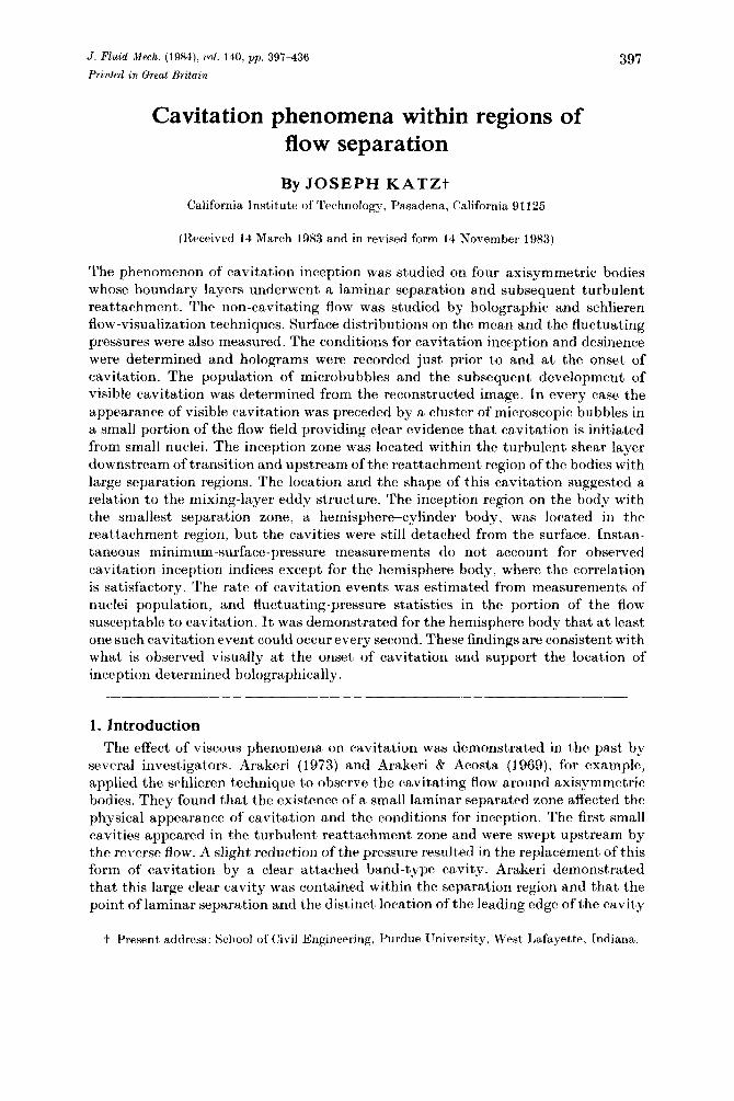
J. Fluid M.ech. (1984), t•ol. 140, pp. 397-436
Printed in Great Britain
Cavitation phenomena within regions of flow separation
By JOSEPH KA TZt California Institute of Technology, Pasadena, California 91125
(Received 14 March 1983 and in revised form 14 November 1983)
397
The phenomenon of cavitation inception was studied on four axisymmetric bodies whose boundary layers underwent a laminar separation and subsequent turbulent reattachment. The non-cavitating flow was studied by holographic and schlieren flow-visualization techniques. Surface distributions on the mean and the fluctuating pressures were also measured. The conditions for cavitation inception and desinence were determined and holograms were recorded just prior to and at the onset of cavitation. The population of microbubbles and the subsequent development of visible cavitation was determined from the reconstructed image. In every case the appearance of visible cavitation was preceded by a cluster of microscopic bubbles in a small portion of the flow field providing clear evidence that cavitation is initiated from small nuclei. The inception zone was located within the turbulent shear layer downstream of transition and upstream of the reattachment region of the bodies with large separation regions. The location and the shape of this cavitation suggested a relation to the mixing-layer eddy structure. The inception region on the body with the smallest separation zone, a hemisphere-cylinder body, was located in the reattachment region, but the cavities were still detached from the surface. Instantaneous minimum-surface-pressure measurements do not account for observed cavitation-inception indices except for the hemisphere body, where the correlation is satisfactory. The rate of cavitation events was estimated from measurements of nuclei population, and fluctuating-pressure statistics in the portion of the flow susceptable to cavitation. It was demonstrated for the hemisphere body that at least one such cavitation event could occur every second. These findings are consistent with what is observed visually at the onset of cavitation and support the location of inception determined holographically.
1. Introduction The effect of viscous phenomena on cavitation was demonstrated in the past by
several investigators. Arakeri (1973) and Arakeri & Acosta (1969), for example, applied the schlieren technique to observe the cavitating flow around axisymmetric bodies. They found that the existence of a small laminar separated zone affected the physical appearance of cavitation and the conditions for inception. The first small cavities appeared in the turbulent reattachment zone and were swept upstream by the reverse flow. A slight reduction of the pressure resulted in the replacement of this form of cavitation by a clear attached band-type cavity. Arakeri demonstrated that this large clear cavity was contained within the separation region and that the point oflaminar separation and the distinct location of the leading edge of the cavity
t Present address: School of Civil Engineering, Purdue University, West Lafayette, Indiana.

398 J. Katz
were closely related. This form of cavitation was altered when the separation zone was removed either by tripping the boundary layer or by increasing the freestream velocity. The cavity became unstable and intermittent until finally no form of attached cavitation could be maintained. Of the many other works, we may mention those ofV an der Meulen ( 197 6) and Gates ( 197 7), who confirmed Arakeri' so bservations on bodies having a laminar separation, and Kermeen & Parkin (1957), for example, who studied the cavitating flow behind sharp-edged disks.
These previous results led Arakeri & Acosta (1979) to classify the various axisymmetric test bodies according to their viscous flow characteristics and resulting cavitation scaling trends. The first group includes the bodies with a large separation region, such as the sharp-edged disks tested by Kermeen & Parkin. They observed that the first visible cavities appeared within the shear layer and suggested that cavitation inception occurred in the area of the large vortices in the mixing zone, to paraphrase their words. The inception index of this group was characterized by a strong dependence on the Reynolds number.
The second group included the bodies with smaller separated zones such as the hemispherical headform body, where the neighbouring surface affected the development of the mixing layer. Cavitation inception occurred near the reattachment zone owing to the large pressure fluctuations there. This observation was made earlier by Arakeri (1975) and supported later by Huang (1979), who respectively measured pressure peaks of 25 and 45% of the dynamic head. The cavitation-inception index showed a weak dependence on the Reynolds number, and its value was close to, but still larger than, the absolute value of the pressure coefficient in the separation zone. The third group of bodies had a very small separation zone, such as the ITTC headform (Arakeri 1973). The cavitation-inception index was independent of the Reynolds number, and his upper bound was the absolute value of the pressure coefficient in the separation zone. The fourth group included the cases where the laminar boundary layer underwent natural transition to turbulence without separation. This group was characterized by travelling bubbles or attached patchy cavitation downstream of the minimum pressure point. The Schiebe body (see Gates 1977; VanderMeulen 1976) was a typical example of this group.
Motivated by the suspicion that the height of the separation zone played a dominant role in cavitation phenomena, Arakeri (1979) proceeded to change this height by means of a small downstream-facing step at the tangency point of the hemispherical body. He showed that even for a step height less than 1% of the body diameter there was a remarkable increase in the inception index, and that beyond 1% the cavitation number approached an asymptotic value that depended only on the Reynolds number.
The preceding investigations of cavitation and its relation to flow separation form the background to the present work. Related material can be found in the recent state-of-the-art review of cavitation by Arndt (1981) and of bubble dynamics by Plesset & Prosperetti (1977).
2. Scope of the present work The present work was focused on cavitation that occurs near the surface of a body
subjected to a laminar separation, followed by free-shear-layer transition and turbulent reattachment. The fully wetted and the cavitating flows past the test bodies (shortly to be described) were visualized by means of holography and the schlieren technique. These observations assisted in relating the location and the physical appearance of cavitation to different flow phenomena such as the location and the

Cavitation phenomena within regions of flow separation 399
dimensions of the separated region and the eddy structure in the shear layer. An attempt was made to follow the development of cavitation from micro to macro (visible} scale in order to study the role of the 'nuclei', or the sources of cavitation. Surface distribution of the mean and the fluctuating pressure were also measured. These pressure studies are described in detail by Katz (1981} and are discussed only briefly here.
Following the presentation of these experiments an attempt is made to estimate the rate of cavitation events by combining some of the major contributing factors. These factors include the nuclei population and size distribution, the pressurefluctuation peaks' frequency and probability of occurrence, and the location of the observed cavitation-inception region. These estimates confirm some of the holographic observations by demonstrating that the pressure peaks and the flux of freestream bubbles through the inception region are sufficient to initiate cavitation.
3. Experimental apparatus and procedures 3.1. Water tunnel and test bodies
The experiments were carried out in the Low Turbulence Water Tunnel (LTWT} at the California Institute of Technology. The rectangular test section is 2.50 m long and its cross-section expands from 0.3 x 0.3 m at the entrance to 0.36 x 0.3 m at the exit. The settling (stagnation) chamber provides a contraction ratio of 16: 1. Two honeycombs and three damping screens assist in reducing the test-section turbulence level to about 0.04% (for details see Gates 1977}. The tunnel maximum speed is 7.3 mjs, and the pressure can be lowered from atmospheric conditions by a vacuum pump.
The results of Arakeri (1979} on the hemispherical bodies with downstream-facing steps are the starting point of the present investigation. Based on this work, we chose four bodies varying in the size of their laminar separation region. These bodies are the hemispherical headform with a smooth tangency, and the hemispherical headform with a 1 mm downstream-facing step at the tangency point, both 2 in. in diameter. In addition, we chose two bodies with the maximum possible separation region; namely flat-faced cylinders of two different sizes, 2 in. and 0.5 in. diameter. The bodies were mounted on a two-bladed sting support and were 0.33 m long. Each headform was built several times for the different experiments. The cavitation tests and observations were made with a smooth body; the mean-pressure measurements were made on a body with a series of surface-pressure taps, and the pressure-fluctuation studies were made on a body with a special drive mechanism that supported and translated a flush-mounted transducer (for details see Katz 1981}.
3.2. The holography system
Holography is the only existing technique that allows direct observation of microparticles and bubbles in the flow, thus providing information on their location, shape and size. This method involves the reconstruction of a three-dimensional image of a sample volume and carrying out all the observations and measurements in the image field at any desired magnification. The hologram itself is a record of the interference between two coherent light waves, the first one a reference beam and the second one the light diffracted from objects in the illuminated sample volume. Illumination of the hologram with another coherent light source results in the formation of a three-dimensional image of the original objects (for further information see Collier, Burkhardt & Lin 1971 ).
The technique chosen for the present work is the lensless Fraunhofer holography,

400
CD @ Q) ® CD ® G)
® ® @) Q}) @ @
He-Ne laser
Autocollimator
Back mirror
Spatial filter
Cooling-water inlet and outlet
Flashlamp reflector
Helical flashlamp
R11by rod
Tngger transformer
Flash lamp power source
Polarizer
Pockel's cell
Spatial filter
Alignment system
J. Katz
@ Front mirror
QY Beam splitter
@ Pin diode
Q]l Oscilloscope
@ Microscope objective
@ Spatial filter (pinhole)
® Collimating lens
@ Pockel's-cell power source
@ Autocollimator light source
@ Recording film
Pulsed-laser generator
~
Collimating and beam-expanding components
11 FIGURE 1. A schematic description of the holocamera.
@ Recording film
which is suitable only for the far field of small objects. A schematic description of the holocamera is presented in figure 1. As shown there, the light source is a pulsed ruby laser whose high intensity is essential for the required short exposure time (around 20 ns). The wavelength of the generated light is 0.6943 Jlm, and the beam is expanded and collimated before illuminating the sample volume. Part of this light is diffracted by the objects in this volume and interferes with the undisturbed remainder of the beam. The resulting pattern is then recorded on a high-resolution film located on the other side of the sample volume.
The reconstruction system, presented schematically in figure 2, consists of a 5 mW He-Ne laser, a beam expander and a spatial filter, a vernier carriage, a magnifying lens, a knife edge, vidicon and a TV monitor. The illumination of the hologram with the expanded, filtered and collimated beam results in the formation of two threedimensional images, a real image and a virtual one (the observations were made in the real-image field). The conventional reconstruction technique is slightly modified by the addition of the knife edge to the focal plane of the magnifying lens. The illuminating collimated beam is focused to a point by the lens on the knife edge, and thereby is partially cut off. The diffracted light, however, can propagate downstream to be recorded by the vidicon and displayed on the television screen. This modification eliminates a major part of the noise and laser speckle. The lens is replaced by a microscope objective and the knife edge is removed when a high magnification (from 100 to 220) is needed. The system was calibrated with a microscope reticle and with samples of water that cont,aincd 10,20 and 50 Jlm particles. The 10 11m particles could be clearly detected on the television screen.

TV camera
CaV?:tation phenomena within regions of flow separation
TV monitor
D Spatial filter-10 pro pinhole
Collimating lens
SmW
expander
FIGURJ<; 2. A schematic description of the reconstruction system.
3.3. Flow visualization and cavitation tests
401
The flow was visualized by heating the body surface with an inserted heater. The heater was adjusted to create a 3 °F difference between the body surface and the freestream water. This temperature difference was sufficient for the observations on the hemispherical and step bodies. Whenever separation occurred, the boundary-layer fluid departed from the body surface and created a hotter layer in the flow above. This hot layer caused the refraction of the illuminating laser light and the resulting image was recorded on the holographic film. The dimensions of the separated zone on the blunt body was quite large and surface heating was satisfactory only for low velocities. These flows were made observable by injecting salt water (1% by weight of MgS04 ) from the hody surface.
The cavitation-inception index O'i (0' is given by (P00 -Pv)flpu~, where P00 is the freestream tunnel pressure, Pv is the vapour pressure at the room temperature, pis the water density and U
00 is the freestream velocity) was determined by observations
under stroboscopic light. The tunnel velocity was kept constant and the pressure was gradually reduced from ambient conditions until the desired form of cavitation appeared. At that moment the output of the tunnel-pressure transducer was frozen and recorded together with the test-section velocity. The water in the tunnel was recirculated for at least 10 min at atmospheric pressure before repeating the experiment. This length of time was required to reduce the amount of freestream bubbles. The measurements of the desinence indices 0' d were carried out by reducing the pressure until cavitation appeared and then slowly increasing the pressure until the last traces of cavitation disappeared.
4. Experimental results 4.1. Blunt bodies
The mean-pressure coefficient CP (given by (P-P00 )/lpU~, P being the loeal pressure), on the surface of the 2 in. blunt body is found to be about -0.5 at xj D = 0.05 (x being the axial location and D being the body diameter), it reaches a minimum of -0.6 at xjD = 0.75, and then recovers back to the freestream value at xj D = 1.75. The results display a weak trend with the Reynolds number. For example, at xjD = 0.75CP varies from -0.55 to -0.65 when the Reynolds number is increased from 7 x 10⁴ to 3.5 x 10⁵ respectively. These results arPin good agreement

402
c::, ----"' ... 2 " s " ~
:;::; Oil ·;; :I::
J. Katz
FIGURE 3. Laser shadow graph of the flow around the 2 in. blunt body; U x = 0.15 m/s.
0.5 Free shear layer\ //'--,,
/ ' ~/ ,-...... ~ ---0.25
' ' I I 1/ I ' ,.
FIGURE 4. A schematic illustration of the injection points and the separation zone on the 2 in. blunt body; Rev= 3.4 x 10⁵ •
with those of Ota (1975), who, in addition to his own measurements, provides the results of other studies on sharp-edged bodies. The value of CP on the 0.5 in. body were measured at xj D = 0.5, and the results, being -0.5, are also in good agreement with the measurements at the same location on the larger body.
The holograms of the flow around the slightly heated blunt body (figure 3) provide a clear evidence of laminar separation, followed by transition and the formation of a large eddy structure in the shear layer. As noted before, the flow at a higher velocity

Cavitation phenomena within regions of flow separation
FIGURE 5. The flow field around the 0.5 in . blunt body at U00
= 5.64 mjs: (a) a laser shadowgraph; (b) a sketch of the image.
403
is visualized by injecting salt water from the body surface. A schematic description of the resulting schlieren photograph is displayed in figure 4. As is evident from this sketch, the jets located between xj D = 0.05 and 1.25 are directed upstream owing to the reverse flow in the recirculation zone. Between x/ D = 1.5 and 1.75 the jets change their direction towards the freestream flow, suggesting that reattachment occurred somewhere between these points. Traces of the salt water can be seen up to yj D = 0.43 (y being the radial distance from the surface) , defining the upper boundary of the turbulent mixing layer. The length ofthe separation region and the maximum height of mixing zone were determined from a series of such schlieren photographs. The height, being y j D = 0.4, and the reattachment length , being around xj D = 1.6, did not display a significant dependence on the freestream velocity. These observations are in good agreement with the location of the pressure recovery region and with those of Ota (1975) that were determined by velocity fluctuation measurements.
The results of flow visualization on the surface of the 0.5 in. blunt body are displayed in figures 5 and 6. A laser shadowgraph and a sketch of the flow at U 00 = 5.6 mjs are presented in figure 5, and the dimensions of the separated region

404 J. Katz
2.5 ~ • -8_ • • , ;;., • ... • • • 0 • • • • 8_ • 2.0 - • • • • ->-: • • ... • ~ "' • E "' • ~ 1.5 - • -"' <.)
<::: • reattachment x/D ~
:; + maximum height of shear layer yjD
'" 1.0 1- -<.)
,·~ ... "' > ... 0
it ++t ++ + it ++ +_
'" 0.5 1- + + + + + + + ·x + <t:
I I I 2 4 6 8
Reynolds number U~D x 10-4 v
FIGURE 6. The dimensions of the separation region on the 0.5 in. blunt body.
plotted against the body Reynolds number are displayed in figure 6. The mixing-layer maximum height, being yjD = 0.5, and the reattachment length, being scattered between x/ D = 1.6 and 2.5, are slightly higher than those of the 2 in. blunt body.
Several phenomena can be readily observed when the photographs and holograms of cavitation inception on the blunt bodies are studied. First, as demonstrated in figure 8 (a), the appearance of visible cavitation is preceded by the appearance of a cluster of microscopic bubbles in the separation region. Secondly, when the inception of visible cavitation does occur, as shown in figs 7(a) and 8(b), the phenomenon is explosive, the bubbles are non-spherical, and some of them have an axial 'stringlike' shape.t Thirdly, in a more-developed state, as demonstrated in fig. 7 (b), the cavitation tends to form a series of transverse rings that surround the body. These rings suggest that the cavitation is related to the large-scale eddy structures of the shear layer.
The population of bubbles in the neighbourhood of the shear layer when the body is cavitating downstream is demonstrated in fig. 9. As is evident from this hologram, the larger and non-spherical bubbles appear along a clearly defined line located between xjD = 0.23 and 0.45 and y/D = 0.11 and 0.27 respectively. This line is in good agreement with the location of the separating streamline according to Ota (1975). There are no bubbles above this line and the bubbles below are much smaller and maintain their spherical shape. This hologram is a clear demonstration of the close relation between cavitation and the mixing layer around the blunt body.
The most-probable location of cavitation inception, such as the cluster of small bubbles shown in figure 8, was determined by analysing 25 holograms of the flow around the 0.15 in. blunt body. The results are presented in figure 10 (a, b) as two
t This stringlike cavitation appeared to be the main form of inception behind sharp-edged plates. These findings are discussed at the end of the present paper.

(411)
(b)
Cavitcttion phenomena within regions of flow separation
I
FIGURE 7. Cavitation inception on the 2 in. blunt body: Re0 = 3.6x 10⁵ .
(a) a-= 1.7; (b) a-= 1·6.
405

406 J. Katz
(a)
(b)
FIGURE 8. Holographic images of cavitation on the blunt bodies: (a) Rev= 2.3 x HJ5,tT = 1.21 (2 in. body), the large cavity is located at xjD = 0.89 and yjD = 0.13; (b) Rev= 8.24x 10⁴
, tT = 1.41 (0.5 in. body). The width of each photograph is 6.9 mm.

FIGURE 9. The population of cavities in the separation zone of the blunt body during cavitation inception; Rev = 2.3 x 10⁵, a- = 1.5.
The hologram covers the region from x/D = 0.23-0.45 and from y/D = 0.11-0.27.
~ ~ .. a ""· 0 ;::;:
~ :;::,.. ~
5 ~ ~ s ~ ""· s. ""· ;::;:
"" <8 ""· 0 ;::;:
"' <2.,
~ ~
"' ,g l;l
~ ""· 0 ;::;:
>+--0 -:J
408 J. Katz
0.12 (a)
0.10
0.08
0.06
O.o4
0.02
1.5
Axial distance x/D
0.5
Radial distance y I D
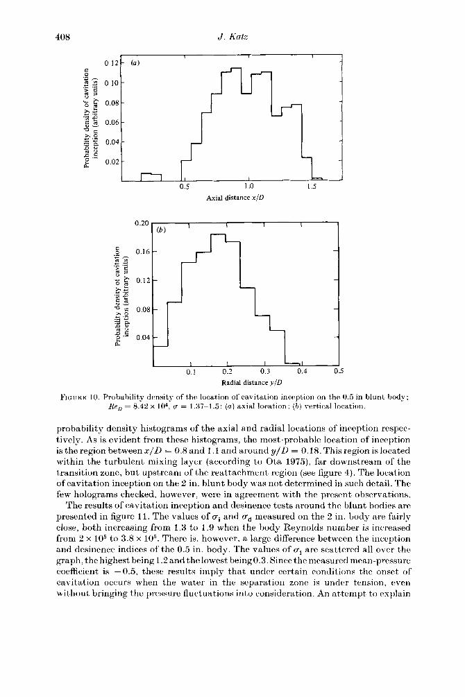
FIGURE 10. Probability density of the location of cavitation inception on the 0.5 in blunt body; Ren = 8.42 x 10⁴ , u = 1.37-1.5: (a) axial location; (b) vertical location.
probability density histograms of the axial and radial locations of inception respectively. As is evident from these histograms, the most-probable location of inception is the region between x/ D = 0.8 and 1.1 and around y/ D = 0.18. This region is located within the turbulent mixing layer (according to Ota 1975), far downstream of the transition zone, but upstream of the reattachment region (see figure 4). The location of cavitation inception on the 2 in. blunt body was not determined in such detail. The few holograms checked, however, were in agreement with the present observations.
The results of cavitation inception and desinence tests around the blunt bodies are presented in figure 11. The values of rri and rT ct measured on the 2 in. Lody are fairly close, both increasing from 1.3 to 1.9 when the body Reynolds number is increased from 2 x 10⁵ to 3.8 x 10⁵ . There is, however, a large difference between the inception and desinence indices of the 0.5 in. body. The values of rri are scattered all over the graph, the highest being 1.2 and the lowest being 0.3. Since the measured mean-pressure coefficient is - 0.5, these results imply that under certain conditions the onset of cavitation occurs when the water in the separation zone is under tension, even without bringing the prm;sure fluctuations into eonsideration. An attempt to explain

Cavitation phenomena within regions of flow separation
2.0 1.4----~--------,.-----"""!KI---...., (a)
1.8 1.2
1.6 1.0 0; ai+CpB
1.4 0.8 0 6
0 0
0 61!1 1.2 0.6
0 cP 6 6 o 6
6 1.0 0.4 6
2.0
1.6
1.0
1.4
0.8
1.2 .. a u""0.6
1.0 t, 0.4
0.8
0.2
0.6
0
0
2.5
6 desinence o inception
0 oo
0
3.0
Reynolds number U~D x 10-s v
• •• • '
•• • • •••
• • • •
3.5
• • •
-. •• • • ' f I • •
' • I •
•
•. e • -CpB o -----------r------------------
0.4
-0.2
0.2
6 cavitation desinence • cavitation inception
6 7
•
8
Reynolds number U~D X 10-4 v
• • 9
FIGURE 11. Cavitation-inception and desinence indices on the blunt bodies. (a) 2 in. body; (b) 0.5 in. body.
409
these results will be made in the discussion that follows. The desinence indices arc more organized, increasing from 1.25 to 1.45 when the Reynolds number is increased from 5.7 x 10⁴ to 9.4 x 10⁴ . The present values of O"ct are in good agreement with the measurements ofKermeen & Parkin ( 1957) behind sharp-edged disks. Their cavitation indices increase from about 1.3 to 1.5 when the Reynolds number is increased from 6 x 10⁴ to 9 x 10⁴, and from 1.5 to 2.0 when Rev is increased from 1 x 10⁵ to 3.5 x 10⁵ •
They also observed a large scatter of the cavitation-inception indices that were measured around the smaller bodies.
As noted before, the surface-pressure fluctuations were measured on the 2 in. body with a flush-mounted piezoelectric transducer. The results were analysed by a digital signal processor that computed the probability density and distribution histograms of the fluctuation levels. An example of these histograms is inserted in figure 12; and further details are discussed by Katz (1981). The pressure levels whose probability

410
!.0
p' 0.8
!PIP.,
0.6
0.4
0.2
12 s average no filter ~
0.1% 2.5% • + negative peaks o positive peaks
0.5 1.0
.J. Katz
100
"" 80 x/D" 0.33 c
0 Filtered signal (> 1 Hz)
" 60 Re0 = 3.0 x 10⁵ ~ ·c <;; 'ii c 40
t 20 .t
1.5
Axial distance/diameter x/D
2.0
FIGURE 12. Axial distribution of the pressure fluctuation peaks on the 2 in. blunt body; Re0 = 3.4 x 10⁵ . The results are taken from a series of probability histograms shown in the insert.
p'
!pU;
12 s average no filter ~ 0.1% 2.5%
• 0
+ X
•
I 02 s average 0.1 Hz filter ~
0.1% 2.5%
• •
0
0
v
negative peaks positive peaks
• 0
• • • • • • 0
• 0 0 0 ~~
~--- 0 0 0 0 J;V"" _+ _____ +l ___ + +_ ..... --'\/
i v l! v\ v /v X \ )( / X X
\ / \ /
v
2
Reynolds number U~ D X !0 -s v
3
X
FIGURE 13. Peak values of pressure fluctuations at x/ D = 1.08 on the surface of the blunt body; xj D = 1.07'1.

Ca1'itation phenomena within regions of flow separation 411
of occurrence exceeded 0.1 and 2.5% were chosen to represent the peaks, and a representative axial distribution of these chosen levels is presented in figure 12. As is evident from this graph, the 0.1 % negative peaks reach a maximum of 80% of the dynamic head at xj D = 1.0, drop to 60% at xj D = 1.5 (near reattachment), and then increase again downstream. The peak value at the point of maximum fluctuations, that is at xj D = 1.08, are plotted against the Reynolds number in figure 13. Unlike the cavitation-inception data, these peaks (being between 60 and 80 %) do not display a clear dependence on Ren. These results imply that the scaled surface minimum pressure (the sum of the negative peaks and the mean-pressure coefficient) at xj D = 1.08 is around -1.4. This value may explain the presently measured inception ipndices at low Reynolds number, but it cannot explain either the value of U'; (or U' ctl at high velocities or their dependence on Ren. Thus the observation that cavitation inception occurs far from the blunt-body surface is supported also by the pressure measurements.
To recapitulate, the first traces of cavitation on the blunt bodies appear as a cluster of microscopic bubbles located in the turbulent shear layer, far downstream of transition but upstream of reattachment. The inception of visible cavitation is explosive and some of the first visible bubbles have a 'stringlike' shape. In a more developed state, the cavitation appears as a series of transverse rings, suggesting a relation to the shear-layer eddy structures. The surface mean and fluctuating pressures explain neither the strong Reynolds-number dependence, nor the high values of the cavitation-inception indices.
4.2. Hemispherical and step bodies
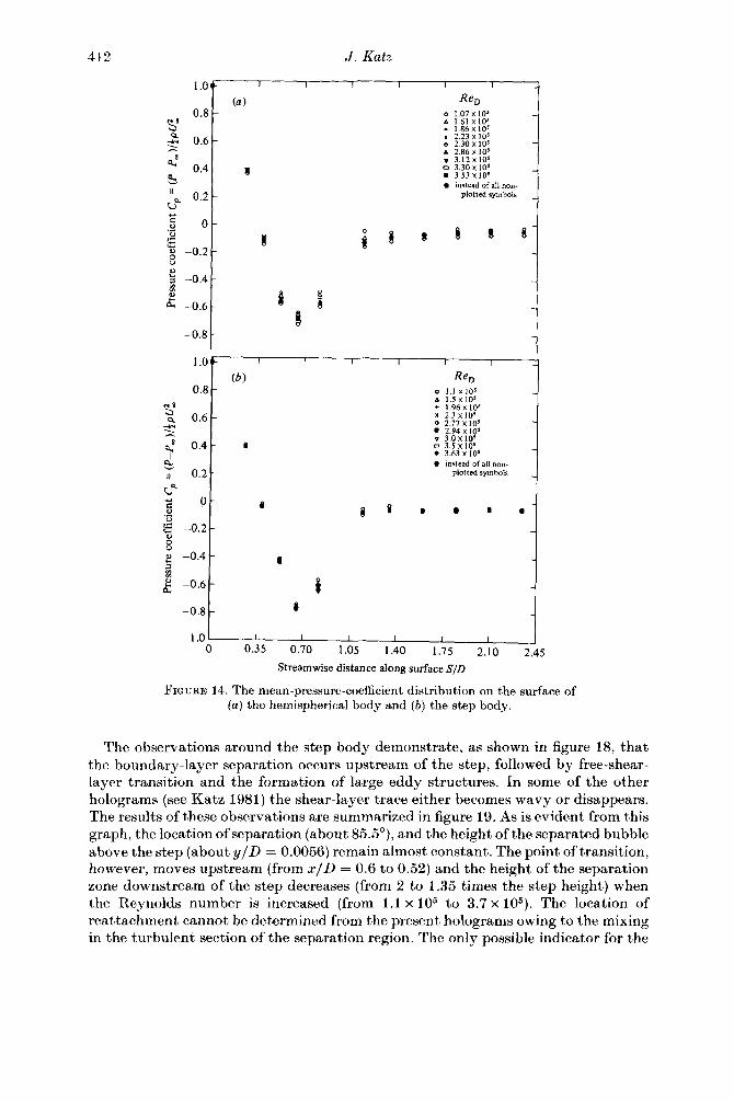
As is evident from figure 14, the mean-pressure coefficient on the surface of the hemispherical and step bodies reaches a minima of -0.7 and -0.76 respectively. Both minima are located at SjD = 0~65 (S being the stramwise distance along the surface), and their values display very little dependence on the Reynolds number. Just downstream of the tangent point on the hemispherical body (at Sf D = 0.82), the value of C Pis about - 0.56, and the results behind the step scatter between -0.59 and -0.65.
Several phenomena are demonstrated by the holograms of the flow around the hemispherical body. First, as shown in figure 15, they confirm the existence of a laminar separation zone, and point at the exact location of separation and free-shearlayer transition to turbulence (assumed to be the point where the separation line becomes wavy). Secondly, as shown in figure 16, the dimensions of the separation region display a strong dependence on the Reynolds number. The point of laminar separation moves downstream (from 84 to 87°), the transition point moves upstream (from xj D = 0.55 to 0.52), and the height of the stable part of the separated region decreases (from yj D = 0.0095to0.0025) when the Reynoldsnumberisincreased (from about 1 x 10⁵ to 3.5 x 10⁵ ). Also shown are the points where the traces of the free shear layer disappear, and the location of maximum surface-pressure fluctuations. The latter is suggested as an indicator for the reattachment zone, and the results follow the general trend with the velocity. A representative distribution of these surfacepressure fluctuations at xj D = 0.681 is presented in figure 17. At this location the presssure peaks reach a maximum of 18% when the Reynolds number is 1.1 x 10⁵
,
and at higher velocities this maximum moves upstream. Unfortunately, since the frequencies of fluctuations on the hemispherical body are fairly high (up to 3500Hz), the 0.1 in. diameter transducer cannot resolve the full extent of the spectrum. Thus the real fluctuations are probably much higher. According to Huang (1979), who used a pinhole microphone on a larger body, these peaks reach a maximum of 45%.
14 FLM 14(}
412 J. Katz
1.0 (a) Re0
0.8 o 1.07 X !05
'Sa .o 1.61 X 10⁵
+ 1.86X10⁵
Q. 0.6 X 2.23 X 105
~ o 2.30X10⁵
• 2.86x10' 8 • 3.12xto' <l., 0.4 c 3.30x10' I
& a 3.53 X 10⁵
• instead of all non-II
0.2 plotted symbols
u"" ;:: 0 " § 8 ·a 0
* s !
~ ~ '- -0.2 " 0 u
" ... -0.4 ;::!
"' "' i I " ... p... -0.6
~ -0.8
1.0 (b) Re0
0.8 o 1.1 X10'
'Si .o l.SX105
+ 1.96 X 10⁵
0.6 K 2.3 X 10⁵ Q. o 2.77XIO' ~ • 2.94 X 10⁵
8 0.4 v 3.0Xl05
<l., • o 3.Sx tos I a 3.63 X 10⁵
& e instead of all non-
II 0.2 plotted symbols
u"" ;:: 0
i -~ 8 • • • • ~ ..... -0.2 " 0 u
" -0.4 I ... ;::!
"' "' i e -0.6 p...
-0.8 • -1.0
0 0.35 0.70 1.05 1.40 1.75 2.10 2.45 Stream wise distance along surface SID
FIGURE 14. The mean-pressure-coefficient distribution on the surface of (a) the hemispherical body and (b) the step body.
The observations around the step body demonstrate, as shown in figure 18, that the boundary-layer separation occurs upstream of the step, followed by free-shearlayer transition and the formation of large eddy structures. In some of the other holograms (see Katz 1981) the shear-layer trace either becomes wavy or disappears. The results of these observations are summarized in figure 19. As is evident from this graph, the location of separation (about 85.5°), and the height of the separated bubble above the step (about yj D = 0.0056) remain almost constant. The point of transition, however, moves upstream (from xj D = 0.6 to 0.52) and the height of the separation zone downstream of the step decreases (from 2 to 1.35 times the step height) when the Reynolds number is increased (from 1.1 x 10⁵ to 3.7 x 10⁵ ). The location of reattachment cannot be determined from the present holograms owing to the mixing in the turbulent section of the separation region. The only possible indicator for the

'!" FIGURE 15. A holographic image of the separation region on the hemispherical body·
Rev = 2.5 x 10⁵ . The width of the screen is 6.9 mm.
C'::l !;)
~. ~ .,, 0 ;::5
~ ;::,-"' ~ "' s ~ .,, ;;::. ~· .... "' ~ "'· 0
~ ~ '";:t, 0 ~
"' ~ !;)
a "'· 0 ;::5
*"' -w

414
0.70
0.65
0.55
0.50
0.45
J. Katz
.-----------~----------,-----------~10
•
•
0
0
6
6
0 0
•
0
/ Height of separation • zone (laminar)
•
0
• • • • • • •
o separation
•
6 transition in free shear layer
D trace disappears \l reattachment
•
0 (pressure fluctuations)
6 6 6o
6
0 o Oo o o o
0 0 0 0
2 3
Reynolds number U_D X w-s v
4
8
6
4
2
0 X
Cl ......_ ;., ... .';: "' a "' ~ :a ·;:; :I:
FIGURE 16. The location of separation, transition, reattachment and the height of the laminar part of the shear layer on the hemispherical body.
reattachment zone is the location of maximum surface-pressure fluctuations behind the step. A representative axial distribution of these fluctuations is presented in figure 20. As is evident from the results, the 0.1 % negative peaks reach a maximum of 22% at xjD = 0.71. As discussed by Katz (1981), the location of this maximum moves upstream (from xf D = 0.72 to 0.68) when the Reynolds number is increased (from 1.4 x 10⁵ to 3.6 x 10⁵ ). The value of this maximum, however, remains almost constant.
Three distinct forms of cavitation can be observed on the surface of the hemispherical body. The first form, not necessarily associated with separated flows (see Gates 1977), is the travelling-bubble cavitation. The second type, whose connection to separated flows was first established by Arakeri (1973) and later verified by Gates (1977) and Vander Muelen (1976), is the band type of cavitation. When the water tunnel is filled with a large number offreestrcam bubbles, the band-type cavity partially disappears, to be replaced by what seems to be a mixture of band and travelling-bubble cavitation. Another form, the bubble-ring cavitation, observed by Parkin & Kermeen (1953) was not detected on the hemispherical body during the present observations. All the sources mentioned above confirm that several bubbles whose dimensions are comparable to the separated zone height can be observed prior to the formation of the band, first near the reattachment point, and then within the recirculation zone. These bubbles exist either in a 'steady' form (bubble-ring cavitation) or as an

Cavitation phenomena within regions of flow separation 415
0
0.1% 2.5%
• + negative peak
o " positive peak
p'
!pU:,
2 3
Reynolds number U~D X w-s
FIGURE 17. Pressure fluctuation peaks at xj D = 0.681 on the surface of the hemispherical body.
intermediate stage that transforms very fast to a large cavity that occupies most of the separated region. The hologram presented in figure 21 and the detailed bubble distribution map in figure 22 verify this observation and provide us with clear evidence of the origin of cavitation on the hemispherical body. The displayed cluster of microscopic bubbles seems to be concentrated in a narrow region, near xj D = 0.6, close to the previously predicted location of the reattachment zone (see figure 16). These bubbles are detached from the surface, and their diameters vary from 10 to 300 11m (actually only one bubble is larger than 200 !liD). Some appear as far as 1.5 mm from the surface, an order of magnitude larger than the size of the laminar part of the separated zone. Since the transition region at these flow conditions is located near xj D = 0.52 (figure 16) all the cluster of bubble is confined to the turbulent section of the separated region. Some bubble no doubt are swept by the reverse flow to the stable part of the separation zone and others may be entrained by the mean flow. Thus the separation region may subsequently appear full of bubbles. However, the present results point clearly at the origin of cavitation on the hemispherical body; namely within the turbulent portion of the flow-separation region. The transition from this microcavitation to a fully developed band occurs very rapidly. The process starts usually at some point (but at the same axial location) and expands all around the body. As noted before, Arakeri (1973) demonstrated that the cavity is contained within the separated zone and that the point of laminar separation and the location of the cavity's leading edge are closely related. The present observations confirm these findings (at least qualitatively), as demonstrated in figure 23.
The conditions for the onset of the various types of cavitation on the hemispherical body are presented in figure 24. As is evident from the results, the inception indices of travelling bubble cavitation, being scattered between 0.6 and 0.82, are fairly close to the lowest surface mean-pressure coefficient, Cpmin· The inception indices of

*'" ..... Ol
~
~ N
FrOl:RE 18. A schlieren hologram of t he separation region on the step body; Rev = 1.7 x 10⁵. The height of t he step is 1 mm.

0.3
P'
!PU:. 0.2
0.1
Cavitation phenomena within regions of flow separation
0.60 0 0
Q !:; --..._
"' ..... !:; 0
~ !:; !:; Q)
0.55 a .~
!:;
::2_ Q) u c: ~ 0.50 :.a
'" ·;; < • • •
0.45 .. .. ..
e e e
• separation
!:; transition in free
'21 shear layer 0 o trace disappears
t;lfp. !:; 6
!:; !:;
!:; ~ !:; !:; ~:;6 !Y&
,& !:; "" !:;
I • • • • • ••• •• • • • ••• •
2 3
Reynolds number U~D x 10-s v
4
O.Q3
8. 0.02 2
~ Q)
E "' :§_
0.01 ~ ·o:; ::r::
0
FIGURE 19. The location of separation, transition and the height of the separated zone on the step body.
0.1% 2.5%
• + negative peak 0 0
0 0 0 X positive peak
0.6 0.7 0.8 0.9
Axial distance/diameter x/D
FIGURE 20. Axial distribution of thP surface-pressure-fluctuation peaks on the step body; Rev= 2.89 x 10⁵ .
417

""" ....... 00
~
~ N"
FIGURE 21. A hologram of cavitation inception on the hemispherical body; Rev= 3 x 10⁵, cr = 0.607. The screen covers the region between xj D = 0.53 and 0.67.

Cavitation phenomena within regions of flow separation 419
Bubble diameter (I'm) 0-20 20-50 50-75 75--100 100-150 150--250 250-350
a 30 13 2
Number of bubbles with diameter s:: ,b , 29 , 5 , 2 , 3 , , , , be tween (I'm) 0-20 :8 27 9 3 l l 20-50 u c
"' "' d 12 2 l
e 30 4 2 2 l
riD 0.1
r-- 9 8 9 I 13 7 II 16 9 10 8 II
'13 9 0 0 l I 0 0 0 0 0 0 0 0
l ~r--8 9 12 I 8 II 19 12 13 14 7 7
~ 14 0 0 0 I 0 0 0 0 0 0 0 0 I r----:-- 13 10 I 8 8 16 8 @ 22 9 12
,__Q_~ ll 0 o I 0 0 4 0 2 0 0
7 0 0 9 14 I 17 9 0 ® 0 0 34 8 r---:2:---r--u 7 0 0 I 0 I 5 0
10 0 0 ~~ 0.5 0.6 0.7 x/D
FIGURE 22. A map of bubble population on the hemispherical body during cavitation inception; Ren = 3x 10⁵ , u = 0.607.
band-type cavitation scatter between 0.35 and 0.6, and the desinence indices vary between 0.46 and 0.56. These results are in good agreement with other studies of cavitation around hemispherical bodies. Gates (1977), for example, found 0'1 to be between 0.55 and 0.65, Arakeri's (1979) results are Elcattered between 0.57 and 0.59, Holl & Carroll (1979) measured 0.56 for the present range of Reynolds numbers, Huang's (1979) indices are around 0.61 for a higher Ren, and Arakeri's (1973) results vary between 0.75 and 0.85. A comparison between the inception indices of band cavitation and the minimum pressure in the separation zone (the sum of the mean, CpB• and the negative peaks of fluctuations) demonstrates that the onset of cavitation in the reattachment region occurs when the fluid is under tension. We return to this interesting point subsequently.
As demonstrated in figure 25, the first form of visible cavitation around the step body is the bubble-ring cavitation. The bubbles appear in one or two distinct axial locations behind the step and create a ring that surrounds the body. At a lower pressure these cavities climb over the step and form a band similar to the hemispherical headform. Several phenomena are demonstrated by the holograms recorded before and at the onset of cavitation. First, as shown in figure 26, the earliest detectable traces of cavitation appear as a cluster of microscopic bubbles (only one of them is larger than 50 ).liD), located behind the step and detached from the surface. Secondly, when the cavities become visible, as shown in figure 27, they appear in two distinct sections, the first one being the location of free-shear-layer transition, and the second and bigger 'cavitation centre' appears at the same height but further downstream. Thirdly, figure 28 provides a clear evidence that the bubbles either upstream of the transition region or below the shear layer remain very small and maintain their spherical shape. The zone above the step remained very quiet during these early stages of cavitation, and only a few microscopic bubbles could be seen attached to the surface downstream of the separation point. These small nuclei

FIGURE 23. A hologram of band-type cavitation on a heated hemispherical body; ReD = 3.3 x 10⁵, u = 0.46. The width of the
screen is 6.9 mm and the cavity leading edge is at x/ D = 0.42.
~ ~ 0
~
~ N

a
Cavitation phenomena within regions of flow separation
0.9r---------------~---------------,-l------------~
o travelling bubble inception 0 8 f- • band-cavitation inception
· 6 band-cavitation desinence
© 0
0 0 -
~0 0
~ 0
o o o 8l f8 CO -C . 0.7 ,.._o--------- 0--- --- --=---@ ---- ·pmm . -
0 0 ° 0 0
0 0 © § © 0
~ 0 ° 13 0 • 0.6
~ e -~B ----- t:.- -- ----.-..!Crr.-i -~------ -v---- --
6 6 6 6 • .t_~ O.Sf- ~ YA/d6 666/iA 6 ~ •• ~ !· -
66 ~ ·~ • • • • • ., • 1
0.4
2.5 3.0
• • ••
_j_
3.5
Reynolds number U~ D X 10-s v
-
4.0
FIGURE 24. Cavitation-inception and desinence indices on the hemisphere body.
421
FIGVRE 25. Bubble-ring cavitation on the hemisphere-step body; ReD= 3.6 x 10⁵ , O" = 1.10.
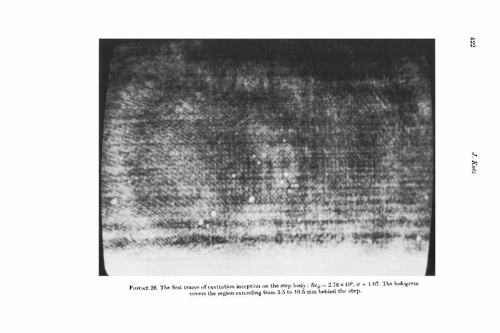
FIGURE 26. The first traces of cavitation inception on the step body; ReD = 2. 78 x 105
, 0' = 1.07. The hologram covers the region extending from 3.5 to 10.5 mm behind the step.
*'" t-:;1 t-:;1
~
~ ~

Cavitation phenomena within regions of flow separation 423
may have been swept upstream by the recirculating flow and settled on the body. The population of bubbles anywhere else in the flow field remained fairly uniform, apnd these results are summarized in the discussion that follows. Finally, the shape and the distinct location of the cavities in figure 27 suggest that cavitation is closely related to the coherent structures in the shear layer (figure 18).
Two probability density histograms that display the location of cavitation inception at two different velocities, 17.5 and 22.2 ftls, are presented in figures 29a, b). These histograms were computed by accumulating data from a series of holograms such as figures 26-28. At 17.3 ftls there are two detectable cavitation centres located around x' I H = 3.25 and 5.75 (x' is the axial distance from the step and His the step height), whereas at 22.2 ftls inception occurs around x' I H = 2.5 and 3.75. Thus the cavitation centres move upstream, and the distance between them decreases as the velocity is increased. A comparison with the results of flow-visualization experiments (figure 19), and to the suggested location of the reattachment zone (found to be at x' I H = 6.9 and 6.0 at U 00 = 17.9 and 21.0 ftls respectively), demonstrates that the onset of cavitation always occurs in the turbulent shear layer, downstream of transition and upstream of reattachment. These results are consistent with the observations on the blunt body (see figure 10). The inception and desinence indices are plotted in figure 30. They vary from around 0.95 to 1.25 when the Reynolds number is increased from 2.4 x 10⁵ to 3.8 x 10⁵ . These results are in good agreement with those of Arakeri (1979), who measured inception indices of 1.3 and 1.35 at higher Reynolds numbers, 4.5 x 10⁵ and 5.7 x 10⁵ respectively. The surface minimum pressure, that is, the sum of GpB ( -0.65) and the negative fluctuation peaks ( -0.22) cannot account either for the present values of si or for their increase with the Reynolds number. Thus the holographic observations are confirmed; namely that the onset of cavitation does not occur near the step-body surface.
To recapitulate, the first traces of cavitation on the two hemispherical bodies appear as a cluster of microscopic bubbles located in the turbulent section of the separated zone and detached from the surface. On the step body the visible cavities emerge in two distinct sections of the turbulent shear layer upstream of the reattachment zone and downstream of the transition region. On the hemispherical body the cavitation starts closer to the body near the reattachment region where the surface minimum pressure is found to agree with the measured inception indices.
5. Discussion 5.1. Conditions for cavitation inception
The present experiments demonstrate that cavitation inception occurs when the microscopic freestream nuclei are exposed to the low-pressure peaks in the turbulent section of the separation region. These observations suggest that both the characteristics of the flow field around the test body and the 'water quality' ;t that is, the amount, the nature and the size distribution of the freestream microbubbles play an important role in the onset of cavitation. A detailed study of these nuclei has been carried out in the present work, which will be described shortly. It has been widely argued that inception of cavitation consists of the growth of these nuclei by the well-known laws of bubble mechanics given e.g. in Knapp, Daily & Hammitt (1970):
.. . 1 [ 2T 4p1l] RR+iR2 =-p Pv+~-P-R-R, (1)
t A term coined by Daniel Oldenziel of the Delft Hydraulic Laboratory.

FIGURE 27. A hologram of bubble-ring cavitation on a heated step body; Ren = 2.78 x 10⁵ , 0' = 1.11.
~ t-:1 ~
~
~ N

Cavitation phenomena within regions of flow separation 425

426 J. Katz
3 (a) ~
"' ·2 ::s
'-C 0 "' c.!.;
2 -~~ "~ ""c:: C.9 ~P. ~" "' (J ~c:: o·-... c:: Q..o
~ "> "' (J
0.55 0.6 x/D
0.65
2 4 6 8 10
x'/H
2 4 6 8 10
x'/H
FIGURE 29. Probability density histograms of the axial location of cavitation inception on the step body: (a) Ren = 2.77 x 10⁵ ; (b) Ren = 3.55x 10⁵.
where R is the bubble radius, T is the surface tension, # and p are respectively the liquid viscosity and density, Pv and ~ are the partial pressures of the vapour and the undissolved gas inside the bubble, and Pis the liquid pressure at infinity. There it is shown that micro bubbles becomes unstable or grow exponentially if the condition
4T P-Pv:::; -3R (2)
is satisfied. Here P can be expressed as the sum of the mean and the fluctuating pressure p = P' + PB, (3)
and by normalizing by the dynamic head we obtain
P' PB -P00 P 00 -Pv 4T 1 ITT2+ 1 U2 + l_ TT2 ----2Pu-oo 2P oo 2Pu-oo 3RlpU~·
(4)

Cavitation phenomena within regions of flow separation 427
0.8 1.4
6 6 6
0.6 6 6~ ~ 0
1.2 6 0 6 6 0
o +CpB 6 ~6 6 'S t 0 c§ 0 is 6 £t
0.4 "i 1.0 ~ ~0 'l
& ~ ~
0.2
0.8 o cavitation inception
6 cavitation desinence
0
0.6 0
~~ ~ ~, ~ 0 %~ 0 1i!
-0.2 Band cavitation_/
0
0.4
-0.4 2 3 4
Reynolds number U~D x 10-s v
FIGURE 30. Cavitation-inception and desinence indices on the hemisphere-step body.
The first term is the fluctuating-pressure coefficient C~, the second is C PB and the third term is the cavitation index. Thus the condition for bubble instability or growth can be expressed as
I 4T 1 Cp+CPB+O"i =- 3R1. U2 = !10".
2P oo (5)
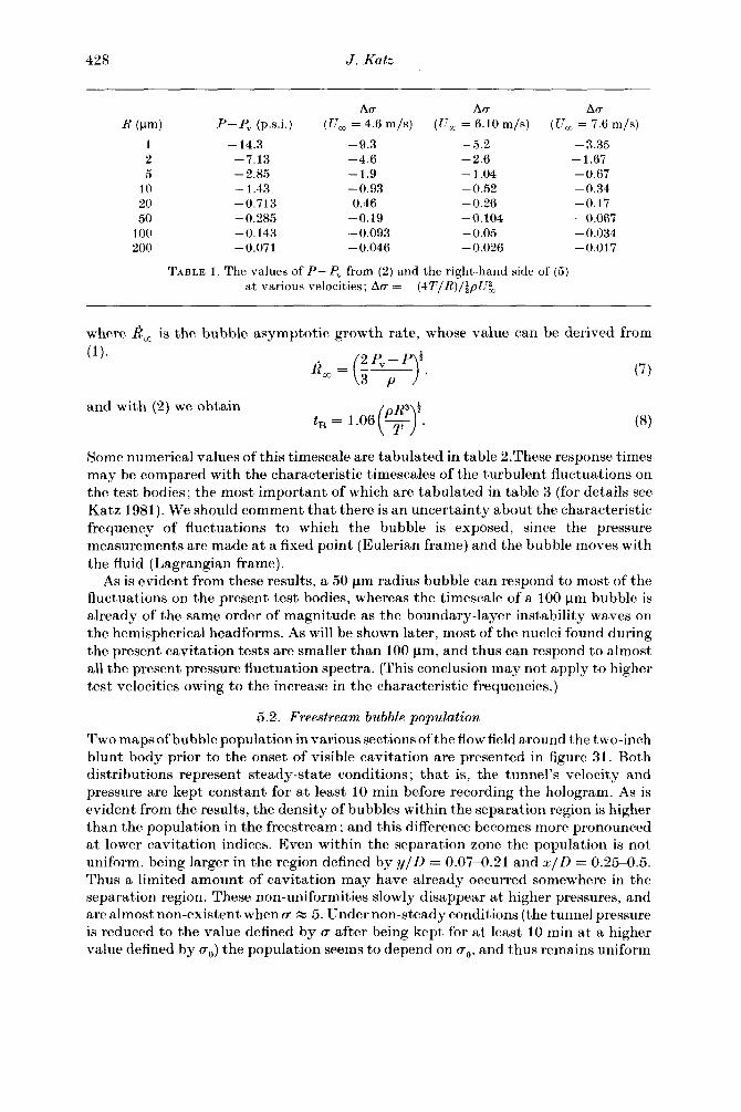
The left-hand side of this equation contains the terms that depend only on the characteristics ofthe flow field, whereas the 'water quality' is expressed by the bubble radius in the denominator of the right-hand side. The importance of this term may be seen by the numerical values in table 1.
As is evident from these results, a larger tension (almost one atmosphere) is required to bring a 1 11m bubble to an unstable state. However, the effect of the right-hand side of (5) becomes negligible either when the bubble radius exceeds 100 11m or when the freestream velocity is sufficiently large. We should keep in mind that the cavitation nucleus has to be exposed to the low-pressure region for a sufficiently long time, and that when pressure fluctuations are considered their period must be long enough for the bubble to respond. As suggested by Arndt & George (1978), the characteristic response time tB of a vapour bubble can be estimated as
(6)
428
R(J.!m)
1 2 5
10 20 50
100 200
J. Katz
t'l.rr t'l.rr t'l.rr P-Pv (p.s.i.) (Uro = 4.6 m/s) (U00 = 6.10 m/s) (U00 = 7.6 m/s)
-14.3 -9.3 -5.2 -7.13 -4.6 -2.6 -2.85 -1.9 -1.04 -1.43 -0.93 -0.52 -0.713 0.46 -0.26 -0.285 -0.19 -0.104 -0.143 -0.093 -0.05 -0.071 -0.046 -0.026
TABLE 1. The values of P-Pv from (2) and the right-hand side of (5) at various velocities; t'l.rr = -(4T/R)dpU~
-3.35 -1.67 -0.67 -0.34 -0.17 -0.067 -0.034 -0.017
where 1(_0
is the bubble asymptotic growth rate, whose value can be derived from (1 ).
R = ('!:_Pv-P)l 00 3 p , (7)
and with (2) we obtain (8)
Some numerical values of this timescale are tabulated in table 2.Thesc response times may be compared with the characteristic timescales of the turbulent fluctuations on the test bodies; the most important of which are tabulated in table 3 (for details see Katz 1981). We should comment that there is an uncertainty about the characteristic frequency of fluctuations to which the bubble is exposed, since the pressure measurements are made at a fixed point (Eulerian frame) and the bubble moves with the fluid (Lagrangian frame).
As is evident from these results, a 50 fJm radius bubble can respond to most of the fluctuations on the present test bodies, whereas the timescale of a 100 fJm bubble is already of the same order of magnitude as the boundary-layer instability waves on the hemispherical headforms. As will be shown later, most of the nuclei found during the present cavitation tests are smaller than 100 fJm, and thus can respond to almost all the present pressure fluctuation spectra. (This conclusion may not apply to higher test velocities owing to the increase in the characteristic frequencies.)
5.2. Freestream bubble population
Two maps of bubble population in various sections of the flow field around the two-inch blunt body prior to the onset of visible cavitation are presented in figure 31. Both distributions represent steady-state conditions; that is, the tunnel's velocity and pressure are kept constant for at least 10 min before recording the hologram. As is evident from the results, the density of bubbles within the separation region is higher than the population in the freestream; and this difference becomes more pronounced at lower cavitation indices. Even within the separation zone the population is not uniform, being larger in the region defined by yjD = 0.07--0.21 and xjD = 0.25--0.5. Thus a limited amount of cavitation may have already occurred somewhere in the separation region. These non-uniformities slowly disappear at higher pressures, and are almost non-existent when a- ::::::: 5. Under non-steady conditions (the tunnel pressure is reduced to the value defined by a- after being kept for at least 10 min at a higher value defined by a-0 ) the population seems to depend on a-0 , and thus remains uniform

Cavitation phenomena within regions of flow separation 429
R (j.!m) tB (s)
1.2 x 10⁻⁷
5 1.4 x 10-• 10 3.9 x 10-• 20 1.1 X 10⁻⁵
50 4.3 x to-s 100 1.2 x 10-•
TABLE 2. Estimated characteriRtic bubble-response t'ime according to (8)
Boundary-layer waves- Turbulent- Step body Blunt body
ucn (m/s) Ren hemisphere (s) hemisphere (s) (s) (s)
3.1 1.6 X 10⁵ 1.25 x 10⁻³ 3.8 x 10⁻³ 7.4 X 10⁻³ 6.1 X 10⁻²
4.6 2.3 X 10⁵ 5.7 x to-• 2.1 x 10⁻³ 4.4 x to-a 4.0 x 10⁻²
6.1 3.1 X 10⁵ 3.7 x to-• 1.4 X 10-a 3.1 X 10⁻³ 3.0 X 10⁻²
7.3 3.8 X 10⁵ 3.03 X 10⁻⁴ 1.0 X 10⁻³ 2.0 X 10⁻³ 2 . .5 x w- 2
TABLE 3. Characteristic period of pressure fluctuations on the present test bodies
as long as the initial pressure is sufficiently high. The freestream bubble population depends both on the test conditions and on the experimental procedures, as demonstrated in figure 32. Here the number-density distribution N(R), defined by
N(R) = N(~(R 1 + R 2 ))
number of nuclei per unit volume with radii between R 1 and R2
R2-Rl (9)
is plotted against the bubble radius. These results are averaged from more than 30 holograms and show the bubble population outside of the separation region. The amount of air dissolved in the water was kept at about 10 p.p.m. and was measured by a Van Slyke device. Several trends can be readily observed; the most visible is the strong dependence of the nuclei population on the steady-state test conditions and the weak dependence on the instantaneous pressure at the time that the hologram is actually recorded. Thus, for example, when a-0 is changed from about 2.5-4 to about 1.5-1.8 the population of bubbles with radii between 10 and 25 Jlm is doubled and the density of larger nuclei is increased by more than an order of magnitude. The differences are much smaller when we compare the distributions obtained at various values of a- (0.5-0.7. 1.5-1.7 and 2.5-4) but all at the same value of a-0 of about 3. There is also a similarity in the result for which a-0 > 5 and a- is either 1.1 or between 0.5 and 0. 7. The distributions in these conditions are of especial interest since they represent the experimental procedure of the present cavitation-inception tests.
5.3. Rate of cavitation events
Some of the factors that affect the conditions for cavitation inception have already been discussed in the previous sections. Among these arc the population of freestrcam bubbles, the tension required to bring these bubbles to an unstable state, the timescales involved, and the location of the first traces of cavitation.

430
8. "' " u c::
0.4
0.3
~ 0.2 ii
'" u '€ " > 0. I
0
27 5 I
I2 4
..-If, 28 7 VI
_L_
12/ 4
I
0.1 ..__Body front
8. "' " u
0.4
0.3
~ 0.2
ii
'" u '€ > 0. I
0
surface
* 8 I I
I I
* 14
* 9 v 2 /
y 7 3
/2 2 2 2
0.1
30
38
I7
L
36
23
* I
*
* .1:-:::
r"'
• 5
* I
...__Body front surface •
4
5
J. Katz
urn ero u es 1 0-20 1 2 -SO 1 50-75 J with diameter j75-IOOjlOO-ISOj!S0-20o_j
~ 12oo-2sopso-Joo13oo- I
N b fb bbl
...-K~::erboun ....... -I 48 3 lr"' 65 4 of mixing la
~ ~
dary yer
5-1 22 I5 37 6 I
6 l I5 8 33 IO
10 23 7 23 6
0.2 lE 0.3 0.4 0.5 Body surface Axial distance xI D
urn ero u N b fb bbl es 0 -20 0-50 0 75 5 -with diameter 75-100 100-150 IS0-200 between (Jlm) 200-250 250-300 300-
13 __.. K~::erboun _..... f-'W'
9 * II v * 5 I of mixing Ia 1•...-P"' I I
L 8-1 2 * II I * 13 2 I 3 2 2 2 I I
I 8 2 • I2 2 * 12 3 2 1 2 4 3 3 4
I
II 2 * 14 3 • 16 I I 2 I 3 I 2 I
0.2 lE 0.3 0.4 0.5 Body surface Axial distance xI D
Not counted
dary yer
FIGURE 31. Maps of the bubble population near the surface of the 2 in. blunt body: (a) Rev= 2.83 x 10⁵
, rT = 3.55; (b) Rev= 3.06 x 10⁵ , rT = 2.56.
We now make an estimate of the rate at which all of these requirements can be satisfied simultaneously as follows: let Q(R) be the rate at which nuclei or micro bubbles of radius Rare swept into the region where cavitation is observed. These micro bubbles are subject to the pressure fluctuations in the region, and of these fluctuations we take the' significant' ones to be those which occur for at least 0.1% of the time. Thus only 1 o-3 of Q(R) will receive a 'significant' fluctuation, the amplitude of which is

Cavitation phenomena within regions of flow separation
Steady state
• a= a0 = 2.5-4 • a= a0 = 1.5-1.8
Non-l>teady state v a0 "" 3, a= 0.5-0.7 o a0 ""3,a=l.5-1.7 o a0 > 5, a= 0.5-0.7 o a0 >5,a=I.I
Bubble radius (!lm)
431
FIGURE 32. The number-density distribution function of the bubble population in various steady and unsteady water-tunnel pressures.
given m figures 12, 17 and 20. The rate of all such 'likely' cavitation events IS
then Qc(R) = 10-3 Q(R), and to estimate Q(R) we have
Q(R) = N(R)IlR UCA, (10)
where N(R) llR is the concentration of microbubbles in the radius range llR, and Uc is the velocity with which these are convected into the region of cavitation. The cross-sectional area A is taken to be reDo, where a is the observed inception region thickness and D is the local diameter. For the hemisphere bodies we use the estimates of Brown & Roshko (1974) for plane mixing layers:
(11)
xi denoting the point of inception and xtr the location of transition in the shear layers. For the blunt bodies a is estimated from figure 15 as 0.1D (inception occurs between yjD = 0.15 and 0.25). The convection velocity is assumed to be one-half the freestream value U
00• We thus obtain
(12)
as the 'rate' of cavitation events for the hemispherical bodies, and a similar expression
(13)
for the blunt bodies. The locations of xi and xtr for the various test bodies have already been described. Sample calculations of Qc(R) at several speeds and microbubble size

432 J. Katz
uoo R 0.5 in. blunt 2 in. blunt Step Hemispherical 4T 1 (m/s) (~-tm) body body body body -3R 1 pU2 =!!O"
2 00
4.57 (}-10 22 356 83 53 -0.93 1(}-25 0.4 6.5 1.5 0.96 -0.46 > 25 0.02 0.36 0.08 0.05 -0.19
6.1 (}-10 30 474 85 63 -0.52 1(}-25 0.54 8.6 1.6 1.2 -0.26 > 25 0.03 0.47 0.09 0.06 -0.10
7.62 (}-10 37 593 96 79 -0.:34 1(}-25 0.67 10.8 1.7 1.4 -0.17 > 25 0.04 0.59 0.10 0.08 -0.07
TABLE 4. Estimated rate of cavitation events and the corresponding local tension required to bring a bubble to an unstable state. The values in the right-hand column are for 10, 20 and 50 ~-tm radius bubbles.
ranges (for o-0 > 5) are tabulated in table 4 together with the values of !!o- (from (5)) required for cavitation.
These numerical tabulations become meaningful when all the components of the instantaneous minimum pressure coefficient of (5) are known (corresponding to the amplitude of the 0.1% level of the negative pressure fluctuations) and when a sufficient rate of these events occur to justify asserting that cavitation inception indeed occurs. t Sufficient data for this purpose are now available only for the hemisphere body as has been shown. For this case we find from figure 23 that o-i = 0.4~.56 and from figure 17 that 0~ = -0.18 at the 0.1% fluctuation level, and finallythatOpB = -0.56. Thustheavailableamplitudeoftheinstantaneouscavitation index ranges from -0.18 to -0.29. These values should exceed !!o- tabulated in the last column of table 4. From these we may conclude (for the hemisphere body) that 20 J.lm bubbles may be readily cavitated at rates exceeding 1 s-1 for speeds of 6.1 and 7.6 m/s, but not at 4.6 mjs, and that 50 J.lm bubbles cavitate too infrequently to be significant.
These estimates of cavitation events, although summary, are consistent with the location of observed cavitation, the surface-pressure fluctuations and freestream nuclei concentrations. These rates of events change with the freestream population, which, as described, is dependent upon experimental technique. Thus, for example, when these estimates are made for the populations obtained for o-0 = 3, the 10--25 J.lm event rates are multiplied by about 4, which would then tend to raise the observed level of inception index by about 0.05.
Fluctuating-pressure measurements within cavitating regions of the other test bodies are not available for instantaneous cavitation-index estimations. But the' rate' calculations of table 4 are still useful, for they do offer guidelines for interpreting experimental results. Thus, for example, a low event rate, say, of less than l s-1
has a timescale comparable to experimental changes in test parameters, and thus would lead to a large experimental scatter. Inception measurements are therefore more consistent, as shown herein for large bodies and for greater nuclei concentrationssay those occurring for desinence tests.
t The concept of cavitation-event rate and the connection to N(R) is due to Professor E. Silberman and coworkers at the St Anthony Falls Hydraulic Laboratory in a long sPries of reports.

Cavitation phenomena within regions of flow separation 433
Beyond that, the present results on the step and bluff bodies show a consistent Reynolds-number dependence much as the collection of inception data reported by Arndt ( 1981) on sharp-edged disks. In fact these show values of ui up to 3 or even 4 at values of Ren = 1.6 x 10⁶
• From these and our own data it must be concluded that mixing-layer pressure fluctuations greatly in excess ofthe surface ones must exist for these bluff-body flows (i.e. an excess of0.25-0.65 for the 2 in. bluff body and about 0.5 for the step body). In addition, none of these surface-pressure fluctuations reveal an important Reynolds-number dependence, whereas the inception indices do. Thus this aspect of cavitation-inception scaling phenomena remains unexplained.
5.4. Modelling of the pressure field around blunt bodies
The Reynolds-number trend of the cavitation index has been a source of puzzlement for some time. Kermeen & Parkin (1957) tried to explain it with a model consisting of a series of discrete Rankine vortices to represent the flow field behind a sharp-edged disk, but this model did not include the Reynolds-number dependence. Arndt (1976) modified this model by suggesting that the core of the vortex should contain only liquid from the separating boundary layer. A semi-empirical formula was then found in which the cavitation inception index was proportional to the square root of the Reynolds number. However, there is a basic difficulty with a simplified model of this type. As explained by Moore & Saffman (1975) the circulation r of a shear-layer eddy can be estimated to be r = LluA, (14)
where Llu is the velocity difference across the shear layer and A is the distance between neighbouring eddies. Then the pressure Pc in the core of a vortex is
P = P _e(....!._)2 c oo 2 21tr c ,
(15)
where rc is the radius of the core. Thus the pressure coefficient
Pc-Poo ( A )2
l/J(Llu)2 = - 21trc (16)
depends only on the ratio A/rc. This ratio does not depend on the freestream velocity, as demonstrated experimentally by Brown & Roshko (1974) and explained by Moore & Saffman (1975). Thus any simplified model of a train of Rankine vortices evidently cannot explain the presently observed scaling trends of the cavitation index.
5.5. Comment Added in Revision
Recent studies of cavitation behind a two-dimensional sharp-edged plate (Katz & O'Hern 1983) revealed that inception occurred in the secondary streamwise vortices of the shear layer. These three-dimensional turbulent structures were reported first by Konrad (1976) and subsequently by Briedenthal (1978) and Bernal (1981). The strength of these vortices and dependence on flow conditions is not yet known. However, according to Bernal, their position in the flow field can be shifted either upstream or downstream by respectively raising or lowering the Reynolds number. The source of the scaling trends ofthe cavitation-inception indices may well be related to the characteristics of these axial secondary structures. Recall that 'stringlike' cavities were also visible during inception on the blunt bodies (see figure 7), but not on the step body. Possibly the dimensions of the separation region on this latter body are too small for the full development of the three-dimensional structures, leaving the transverse eddies to play the more-dominant role. This speculation suggests that

434 J. Katz
the onset of cavitation on the blunt body occurs where the axial structures are most developed, i.e. as far downstream as possible but upstream of reattachment. As for the step body, inception occurs close to the core of the transverse eddies, and thus appears where these eddies are most likely to form in the shear layer.
6. Summary and conclusions Cavitation phenomena are studied within regions of separated flows adjacent to
axisymmetric bodies. In all of these flows the separation is laminar, followed by a free-shear-layer transition and turbulent reattachment. The test bodies and the dimensions of the associated separated regions differ widely from each other. They are a hemispherical body, a hemispherical headform with a downstream-facing step at the tangency point, and two flat blunt circular cylinders. The non-cavitating flow and the features of the separated regions around each of the test bodies were studied by two optical techniques, holography and schlieren photography. Surface distributions of the mean and the fluctuating pressures were measured over the range of Reynolds numbers available in the test facility. The occurrence of several forms of cavitation was noted, and the conditions for inception and desinence were measured for each of the test bodies. Holograms of the water within and outside of the separated regions were recorded just prior to and at the onset of cavitation. Reconstruction of these holograms then made possible the quantitative evaluation of the population of micro bubbles in various sections of the flow field. The location and the nature of the subsequent visible cavitation originating from these bubbles was also determined from these holograms.
A number of trends and conclusions can be drawn from the present measurements. First, the dimensions of the separation region and the mean-pressure coefficient on the surface of the blunt bodies display little dependence on the Reynolds number. The sizes of the separation zone on the hemispherical and step bodies, however, become smaller as the velocity is increased, but the values of the base-pressure coefficients there remain almost unchanged. The surface-pressure fluctuation peaks, determined from probability distribution histograms, reach 85, 18 and 23% of the dynamic head on the blunt, hemispherical and step bodies respectively. The location of maximum surface-pressure fluctuations on the hemispherical and step headform was assumed to be the reattachment zone.
Secondly, the appearance of visible cavitation on all of the present test bodies is preceded by the appearance of a cluster of microscopic bubbles in a small region of the flow field, namely the cavitation-inception zone. This zone is in the turbulent shear layer, downstream of transition and upstream ofthe reattachment region of the step and the blunt bodies. Both the holograms of these headforms and the tendency of the cavities to form a series of rings reveal that cavitation is related to the mixing-layer main and secondary eddy structures. Unlike the blunt bodies, the inception region of the hemispherical body is located within the reattachment zone; again the onset of cavitation is within the fluid and not attached to the surface.
The direct holographic evidence of the development of cavitation from microscopic nuclei confirm the oft-mentioned claim that inception occurs when a freestream bubble is brought to instability by the pressure-fluctuation peaks. The measured instantaneous minimum static pressure on the surface of the blunt and the step bodies is always larger than the vapour pressure, thus excluding the possibility of inception close to the body. The minimum pressure on the hemispherical headform, however, is negative (under a state of instantaneous tension), indicating that cavitation may occur close to the surflj,ce. The rate of cavitation events, that is, the rate at which

Cavitation phenomena within regions of flow separation 43.5
the freestream bubbles are brought into the inception zone and are exposed to the pressure peaks, is estimated from the experimental results. The contributing factors include the bubble population and size distribution, the dimension of the separation region, the location of cavitation inception, the size of the body, and the freestream velocity. These estimates demonstrate that the tension in the reattachment zone of the hemispherical body and the population of nuclei are sufficient to initiate cavitation.
Surface-pressure fluctuations on the blunt bodies are relatively independent of Reynolds number, whereas the observed inception indices are not. This important cavitation scaling effect remains to be fully explained.
This work was supported by the Naval Sea System Command General Hydrodynamic Research Program, administered by David W. Taylor Naval Ship Research and Development Center, under Contract N00014-80-C-0064. This support is gratefully acknowledged. The author would like to thank Dr A. J. Acosta for his advice and guidance during the course of the present work.
REFERENCES
ARAKERI, V. H. 1973 Viscous effects in inception and development of cavitation on axi-symmetric bodies. Ph.D. dissertation, California Institute of Technology.
ARAKERI, V. H. 1975 A note on the transition observations on an axisymmetric body and some related fluctuating wall pressure measurements. Trans. ASME I: J. Fluids Engng 91, 82-87.
ARAKERI, V. H. 1979 Inception of cavitation from a backward facing step. Intl Symp. on Cavitation Inception. ASME Winter Annual Meeting. N.Y., 2-7 December.
ARAKERI, V. H. & AcosTA, A. J. 1979 Viscous effectR in the inception of cavitation. Int. Symp. on Cavitation Inception, ASME Winter Annual Meeting,.N. Y., 2-7 December.
ARNDT, R. E. A. 1976 Semi-empirical analysis of cavitation in the wake of a sharp-edged disk. Trans. ASME I: J. Fluids Engng 98, 56()--562.
ARNDT, R. E. A. 1981 Cavitation in fluid machinery and hydraulic structures. Ann. Rev. Fluid Mech. 13, 273-328.
ARNDT, R. E. A. & GEORGE, W. K. 1978 Pressure fields and cavitation in turbulent shear flows. In Proc. 12th Symp. Naval Hydrodyn. Washington, D.C., pp. 327-339.
BERNAL, L. P. 1981 The coherent structure of turbulent mixing layers. Ph.D. dissertation, Graduate Aeronautical Laboratories, California Institute of Technology.
BREIDENTHAL, R. E. 1978 A chemically reacting turbulent shear layer. Ph.D. dissertation, California Institute of Technology.
BROWN, G. L. & RoSHKO, A. 1974 On density effects and large structure in turbulent mixing layers. J. Fluid Mech. 64, 775-816.
COLLIER, R. J., BURKHARDT, C. B. & LIN, L. H. 1971 Optical Holography. Academic. GATES, E. M. 1977 The influence of freestream turbulence, freestream nuclei populations and a
drag-reducing polymer on cavitation inception on two axisymmetric bodies. California Inst. Tech. Rep. 183-2 (April).
HoLL, W. J. & CARROLL, J. A. 1979 Observation of the various types of limited cavitation on axisymmetric bodies. Int. Symp. on Cavitation Inception, ASME Winter Annual Meeting, N.Y., 2-7 December.
HUANG, T. T. 1979 Cavitation inception observations on six axisymmetric bodies. Intl Symp. on Cavitation Inception, ASME Winter Annual Meeting, N.Y., 2-7 December.
KATZ, J. 1981 Cavitation inception in separated flows. Ph.D. dissertation, California Institute of Technology.
KATZ, J. & O'HERN, T. J. 1983 Cavitation in large scale shear flows: ASME Pub. 83-FE-33. KERMEEN, R. W. & PARKIN, B. R. 1957 Incipient cavitation and wake flow behind sharp edge
disks. California Inst. Tech. Hydrodyn. Lab. Rep. 85--4 (August).
KNAPP, R. T., DAILY, J. W. & HAMMITT, F. G. 1970 Cavitation. McGraw-Hill.

436 J. Katz
KoNRAD, J. H. 1976 An experimental investigation of mixing in two dimensional turbulent shear flows with applications to diffusion-limited chemical reactions. Ph.D. thesis, California Institute of Technology; Project SQUID Tech. Rep. CIT-8-PU.
MooRE, B. W. & SAFFMAN, P. G. 1975 The density of organized vortices in a turbulent mixing layer. J. Fluid Meek. 69, 465-473.
0TA, T. 1975 An axisymmetric separated and reattached flow on a longitudinal blunt circular cylinder. Trans. ASME E: J. Appl. Meek. 42, 311-315.
PARKIN, B. R. & KERMEEN, R. W. 1953 Incipient cavitation and boundary layer interaction on a streamlined body. California lnst. Tech., Hydrodyn. Lab. Rep. E-35.2 (December).
PLESSET, M.S. & PROSPERETTI, A. 1977 Bubble dynamics and cavitation. Ann. Rev. Fluid Mech. 9, 145-185.
VAN DER MEULEN, J. H. J. 1976 A holographic study of cavitation on axisymmetric bodies and the influence on polymer additives. Netherlands Ship Model Basin, Pub. 509, Wageningen, The Netherlands.