cautions for using aluminum electrolytic capacitors
TRANSCRIPT

8/3/2019 Cautions for Using Aluminum Electrolytic Capacitors
http://slidepdf.com/reader/full/cautions-for-using-aluminum-electrolytic-capacitors 1/410
NOTEDesign, Specifications are subject to change without notice.Ask factory for technical specifications before purchase and/or use.
ALUMINUM ELECTROLYTIC CAPACITORS
CAT.No.2004/2005E(2004.10.1)
1. DC electrolytic capacitors are polarized.
If used with a wrong polarity, it creates an abnormalcurrent resulting in a short circuit or damage to itself.Use DC bipolar electrolytic capacitors for use withuncertain or unknown polarity. DC capacitors cannotbe used in AC circuits.
2. Use within the rated voltage.
If a voltage exceeding the rated voltage is applied, it
may cause characteristic deterioration or damage dueto the increased leakage current.When ripple current is loaded, make sure that thepeak value of the ripple voltage does not exceed therated voltage.
3. Do not use in a circuit which requires rapid
charging or discharging.
If used in a circuit requiring rapid charging or dis-charging, it may cause characteristic deterioration ordamage to itself due to the heat generated inside thecapacitor. In such cases, contact us for our rapid
charging/discharging capacitors.
4. Use within the rated ripple current.
If applied ripple current exceeds rated ripple current,the life of the capacitor may be shortened, or in anextreme case it gets destroyed due to its internal heat.Use high-ripple type capacitors for such circuits.
5. Changes in characteristics due to operating
temperature.
The characteristics of an electrolytic capacitor willchange with a change in the temperature. Such
changes are temporary and the original characteris-tics will be restored at the original temperature (if thecharacteristics are not deteriorated by remaining at ahigh temperature for a long time). If used at a temper-ature exceeding the guaranteed temperature range,the capacitor may be damaged due to the increasedleakage current. Pay attention to the capacitor tem-perature being affected by the ambient temperatureof the unit, the temperature inside the appliance, theheat radiated by another hot component in the unitand the heat inside the capacitor itself due to theripple current.• The electrostatic capacitance is normally shown as
the value at 20˚C-120Hz. It increases as the tem-perature raises and decreases as it lowers.
• The tangent of loss angle (tanδ ) is normally shown
as the value at 20˚C-120Hz. It decreases as the
Please read product specifications before using ELNA products.
The following cautions should be observed when using our aluminum electrolytic capacitors to assure their maximum
stability and performance. When your application design conditions or operating conditions exceed the limit of the
product specification, please contact us. If used under conditions beyond the limit of our specifications, it may cause
defects such as short circuit, open circuit, leakage, explosion or combustion.
Cautions for usage
ambient temperature gets high and increases as it
gets low.
• The leakage current increases as the temperature
gets high and decreases as it gets low.
6. Changes in the characteristics due to frequency.
The characteristics of an electrolytic capacitor will
change according to the change in the operating fre-
quency.
• The electrostatic capacity is normally shown as thevalue at 20˚C-120Hz. It decreases as the frequency
increases.
• The tangent of loss angle (tanδ ) is normally shown
as the value at 20˚C-120Hz. It increases as the
frequency gets high.
• The impedance is normally shown as the value at
100kHz 20˚C. It increases as the frequency lowers.
7. Aluminum electrolytic capacitor life.
The life of an aluminum electrolytic capacitor termi-
nates when it fails due to the deterioration in its elec-
tronic characteristics. Temperature and the ripplecurrent since they especially affect the life. See chart
on page.
8. Changes in aluminum electrolytic capacitors
during storage.
After storage for a long period, whether unused of
mounted on the appliance, the leakage current of an
aluminum electrolytic capacitor will increase. This
tendency is more prominent when the ambient tem-
perature is high. If a capacitor has been stored for
more than 2 years under normal temperature (shorter
if high temperature) and it shows increased leakagecurrent, a treatment by voltage application is recom-
mended. Addition of a protective circuit in the design
of the appliance is also recommended, considering
the effect of the initial increased current.
9. Insulation between the capacitor case and the
cathode terminal.
The capacitor case and the cathode terminal are con-
nected through the electrolyte which has uncertain
resistance. If a complete insulation of the case is
necessary, add an insulator at assembly.
10 . External sleeve.
During a preheating or a hardening of mounting
adhensive may cause a sleeve cracked.
The capacitors are usually sleeved with poly vinyl-
Cautions for Using Aluminum Electrolytic Capacitors

8/3/2019 Cautions for Using Aluminum Electrolytic Capacitors
http://slidepdf.com/reader/full/cautions-for-using-aluminum-electrolytic-capacitors 2/411
NOTEDesign, Specifications are subject to change without notice.Ask factory for technical specifications before purchase and/or use.
ALUMINUM ELECTROLYTIC CAPACITORS
CAT.No.2004/2005E(2004.10.1)
chroraide or poly ethylene terephtharate for the
indication purpose only. Please do not consider it as
an insulation.
11. Fumigation ProcessWhen exporting electronic equipment abroad,
fumigation process may be performed on wooden
packaging material with a halogen (compound) gas
such as methyl bromide. Exercise care as this
halogen gas may corrode capacitors. Also, use
caution to epidemic preventive agent as corrosive
component such as halogen may be contained.
12. Specific Operating Environments
Capacitors may corrode when stored or used in a
place filled with acidic toxic gases (such as hydrogen
sulfide, sulfurous acid, nitrous acid, chlorine, bromine,
methyl bromide, etc.)
If capacitors are used or stored in such environments,
please let us know.
13. Use at a high altitude
The use of capacitors at high altitudes such as on an
airplane causes a large difference between the
internal pressure of the capacitors and the atmos-
pheric pressure. However, there is no problem in use
under atmospheric pressure up to about an altitude
of 10,000 meters. Please check the operation of
electronic equipment at the operating environmental
temperature because the temperature lowers withincreased altitude.
14. Hole pitch adjustment of the PCB to the
capacitors.
Set the hole pitch of the PCB to the lead pitch (the “F”distance in the catalog) of the capacitor. Be careful
since a short circuit, a cut or an increase in the leak-
age current etc. may be caused by the stress given
to the lead wire terminals due to the difference be-
tween the hole pitch and the lead pitch.
15. Capacitors with pressure valves.(1) A part of the capacitor case is made thin to have
the function as the pressure valve in order to pre-
vent explosion due to the rise of inside pressure
when a reverse or excessive voltage is applied to
the capacitor. Once it has worked as a valve, the
whole capacitor needs to be replaced since the
valve will not restore.
(2) When you use a capacitor with pressure valve,
provide certain space above the pressure valve as
below to prevent an interference when it works as
a valve.
16. Double-sided PCB's
When you use electrolytic capacitors on a double-
sided PCB, be careful not to have the circuit pattern
run under where the capacitor is mounted. Otherwise
it may cause a short circuit on the PCB dependingon the condition of mounting.
17. Regarding Connection of capacitors.
• When connecting more than one capacitor in parallel,
over-ripple current may develop in some capacitors
with the current balance lost if resistance values of
the wires to be connected to each capacitor are
different because the resistive component of the
capacitors is close to the circuit resistance value.
Careful consideration shall therefore be given in
designing the circuits to prevent over-ripple current
from flowing.
• When two or more capacitors are arranged in series,
the voltage given to each capacitors shall be kept
below the rated voltage level, by also giving
consideration to the balance of the voltage
impressed on the capacitors. Further, partial
pressure resistor which considers leakage current
shall be provided parallel to each condenser not to
have over-voltage impressed on.
Barance resistance are explained on p.88 of our
Catalog.
1. Cautions for mounting.
(1)Check the ratings (electrostatic capacitance and
rated voltage) of the capacitor before mounting.
(2)Check the polarity of the capacitor to the chassis.
(3)Do not drop the capacitor to the floor. Do not use
the dropped capacitor.
(4)Do not deform the capacitor for mounting.
2. Do not apply excessive pressure to the capaci-
tor, its terminals or lead wires.
(1)Make sure that the contact path of the capacitor
meets the hole pitch of the PCB before mounting.(2)Transient recovery voltage may be generated in the
capacitor due to dielectric absorption. If required,
this voltage can be discharged with a resistor with
a value of about 1 kΩ.
(3)A PCB self-standing (snap-in) type capacitor
should be pushed to the end (till there is no space)
to the PCB for mounting.
(4)Do not set the automatic insertion machine to
clinch the capacitor lead wires too strong.
(5)Pay attention to the impact given by the compo-
nent receptacles of the automatic insertion/mount-
ing machines and the product checker, and fromthe centering operation.
Cautions for Mounting
Diameter of the capacitor(mm)
Required spaceabove the valve(mm)
20 to 35
3.0
18 to less
2.0

8/3/2019 Cautions for Using Aluminum Electrolytic Capacitors
http://slidepdf.com/reader/full/cautions-for-using-aluminum-electrolytic-capacitors 3/412
NOTEDesign, Specifications are subject to change without notice.Ask factory for technical specifications before purchase and/or use.
ALUMINUM ELECTROLYTIC CAPACITORS
CAT.No.2004/2005E(2004.10.1)
3. Soldering.
(1)Do not dip the capacitor into melted solder.
(2)The soldering conditions
Chip type: Please refer to 14 page.
small and large type: 260˚C, 10 s (max.)The preliminary heating and other conditions
described in the catalog or product specifications.
(3)Do not flux other part than the terminals.
(4)If there is a direct contact between the sleeve of
the capacitor and the printed circuit pattern or a
metal part of another component such as a lead
wire, it may cause shrinkage of crack.
(5)When you use the capacitor with its sleeve touch-
ing directly to the PCB, excessive solder tempera-
ture or excessive soldering time may cause the
sleeve to shrink or crack during the heat.
(6)If the application is for extended use, understand
and manage the soldering characteristics to avoid
abnormal current caused by a contact failure
between the capacitor and the PCB.
4. Handling after soldering.
(1)After soldering, do not tilt, push down or twist the
capacitor.
(2)After soldering, do not hold the capacitor as a
handle to carry the PCB.
(3)After soldering, do not hit the capacitor with any
obstacle. If PCB's are piled up for storage, the ca-
pacitor should not touch another PCB or compo-
nent.
5. Cleaning after soldering.
(1)Capacitors must not be clean with halogen based
solvents. If cleaning is required, clean-insured
capacitors should be used within the scope of the
delivery specifications. Clean-insured capacitors
are explained on p.6 of our Catalog.
(2)Recommended cleaning method
Cleaning Solvent : Clean Through 710M, 750H
and 750L;
Pine ALpha ST-100S;
Technocare FRW-14~17;Isopropyl alcohol
Cleaning conditions: The cleaner temperature shall
be 60˚C or less with the
cleaning periods within 5
minutes. After cleaning,
thoroughly rinse the capacitor
with water and dry it together
with the printed circuit board
using hot air for more than 10
minutes.
The hot air shall not exceed the
maximum operating tempera-ture.
Insufficient drying can damage
appearance such as second-
ary contraction of sleeve and
swelling of the base plastic
holder.
(3)Other cleaning liquids:
Cleaning Solvent : AK225AES
Cleaning conditions: Any of immersion, ultrasonicimmersion and steam within 5
minutes, with the exception of
the surface-mount chip ca-
pacitors within 2 minutes.
• CFC substitute (AK225AES) is use prohibition will
be carried out in the future, please avoid use.
• Please consult us regarding other cleaning agents
or cleaning methods.
6. Fixing adhesives and coating materials.
(1)Do not use fixing adhesive or coating material
containing halogen-based solvent.
(2)Before applying the fixing adhesive or the coating
material, make sure that there is no remaining flux
or stains between the PCB and the sealed part of
the capacitor.
(3)Before applying the fixing adhesive or the coating
material, make sure that the detergent etc. has
dried up.
(4)Do not cover the whole surface of the sealed part
(terminal side) of the capacitor with the fixing ad-
hesive or the coating material.
(5)Observe the description in the catalog or the prod-
uct specifications concerning the thermal stiffening
conditions of the fixing adhesive or the coatingmaterial. (If there is no such description, contact
us.) When both discrete and SMT components are
on the same PCB, the fixing material for the SMT
components may cause crack, tear or shrinkage on
the external sleeve depending on the thermal
stiffening condition.
(6)Recommended fixing adhesives and coating
materials
Fixing adhesives: Cemedine 210,501,540,545N,Diabond
DN83K,DA3288,Bond G103
Coating materials: Taffy TF1159,HumiSeal 1B66,1A27NS
1. Do not touch capacitor terminals with bare hands.
You may get electric shock or your hand may be
burnt. Discharge it with a 1 KΩ resistance before use
if necessary.
2. Do not short the capacitor terminals with a con-
ductor.
Do not spill conductive solution including acid or alka-
line solution on the capacitor.
3. Periodical inspections should be established
for the capacitors used in industrial appliances.
The following items should be checked:
(1)Appearance: Check if there is any open valve or
Other Cautions
8/3/2019 Cautions for Using Aluminum Electrolytic Capacitors
http://slidepdf.com/reader/full/cautions-for-using-aluminum-electrolytic-capacitors 4/413
NOTEDesign, Specifications are subject to change without notice.Ask factory for technical specifications before purchase and/or use.
ALUMINUM ELECTROLYTIC CAPACITORS
CAT.No.2004/2005E(2004.10.1)
leakage.
(2)Electronic performance: Check the leakage cur-
rent, the electrostatic capacitance, the tangent of
loss angle and other items described in the catalog
or the product specifications.
4. Take the following measures in case of emergency.
(1)If you see gas coming out of the capacitor valve
when the set is in operation, turn off the power
switch of the unit or unplug the power cord from
the outlet.
(2)Keep your face away from the capacitor pressure
valve, since the high temperature gas at over
100˚C bursts out when the valve works. If the gas
gets into your eyes or your mouth, wash your eyes
or your mouth. Do not ingest the capacitor electro-
lyte. If the electrolyte gets on your skin, wash it out
with soap.
5. Storing conditions.
(1)Avoid high temperature or high humidity when
storing capacitors. Keep the storing temperature at
5˚C to 35˚C and the relative humidity not more than
75%.
(2)The leakage current of an aluminum electrolytic
capacitor tends to increase when stored for a long
time. This tendency becomes more prominent if the
ambient temperature is high. The leakage current
will be decreased by voltage application. If
necessary, treatment by voltage application should
be made on the capacitors which have been stored
for a long period (more than 2 years after
production).
(3)Do not store capacitors at a place where there is
a possibility that they may get water, salt or oil spill.(4)Do not store capacitors at a place where the air
contains dense hazardous gas (hydrogen sulfide,
sulfurous acid, nitrous acid, chlorine, ammonia,
etc.).
(5)Fumigation treatment with toxic gas covering the
whole wooden container frames as moth proofing
during shipment may leave residual toxic gas.
(6)Do not store capacitors at a place where it gets
ultraviolet or radioactive rays.
6. Disposing of capacitors.
(1)Punch a hole or crush the capacitors (to prevent
explosion) before incineration at approved facility.
(2)If they are not to be incinerated, bring them to a
professional industrial waste disposal company.
7. Other notes.
Please refer to the following literature for anything not
described in the product specifications or the catalog.
(Technical report of Japan Electronics and Information
Technology Industries Association, EIAJ RCR-2367B
“Guideline of notabilia for fixed aluminum electrolytic
capacitors for use in electronic equipment”)
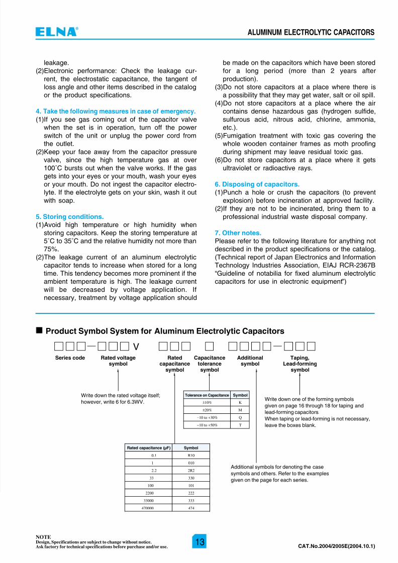
Product Symbol System for Aluminum Electrolytic Capacitors
Series code Taping,Lead-forming
symbol
Rated voltagesymbol
Ratedcapacitance
symbol
Capacitancetolerancesymbol
Additionalsymbol
Write down the rated voltage itself;however, write 6 for 6.3WV.
V
Additional symbols for denoting the case
symbols and others. Refer to the examples
given on the page for each series.
Write down one of the forming symbols
given on page 16 through 18 for taping and
lead-forming capacitors.
When taping or lead-forming is not necessary,
leave the boxes blank.
±10% K
±20% M
−10 to +30% Q
−10 to +50% T
Tolerance on Capacitance Symbol
0.1 R10
1 010
2.2 2R2
33 330
100 101
2200 222
33000 333
470000 474
Rated capacitance (µF) Symbol