cause analysis and control measures of cracks in filling ... · convenient design and construction,...
TRANSCRIPT
CHEMICAL ENGINEERING TRANSACTIONS
VOL. 59, 2017
A publication of
The Italian Association of Chemical Engineering Online at www.aidic.it/cet
Guest Editors: Zhuo Yang, Junjie Ba, Jing Pan Copyright © 2017, AIDIC Servizi S.r.l. ISBN 978-88-95608- 49-5; ISSN 2283-9216
Cause Analysis and Control Measures of Cracks in Filling
Wall of Reinforced Concrete Structure
Huiyan Luana, Qiuyan Kanga, Teng Liub
aEngineering Management, Yantai Nanshan University, Yantai 265713, China bCivil Engineering, Southeast University, Nanjing, China
The crack problem of the filler wall in reinforced concrete structure appears more and more frequently with its
wide application. This paper analyzes the causes of the cracks in the block filler wall in the frame of the
reinforced concrete structure from the aspects of external environmental factors and intrinsic material factors,
and puts forward the corresponding prevention and control measures. The control measures can improve the
safety, comfort and quality of housing construction to avoid the trouble to the daily life of the residents
because of cracks.
1. Introduction
Filler wall in reinforced concrete structure, with strong integrity, strong corrosion resistance, strong durability,
convenient design and construction, can be used to larger and more flexible space partition room in column
bearing system, and has been applied more widely in the field of construction. But there is a common quality
of engineering defects - cracks. Cracks have a number of negative effects on the building. For example, it will
cause the heat bridge effect even weaken the wall insulation and thermal insulation properties. The existence
of cracks reduces the durability, applicability, bearing capacity and seismic performance of buildings. Also, it
can greatly reduce the beauty of the building appearance. When the cracks are serious to a certain extent, it
will affect the structural safety of buildings and affect people's normal life (Khankhaje et al., 2017).
2. Definition of related concepts
2.1 Meaning of reinforced concrete structure
The reinforced concrete structure is made of concrete reinforced with steel-reinforced bars, which are formed
by linear rods such as beams and columns to support the horizontal and vertical loads and are divided into
small spaces by filling walls to meet the functional requirements.
2.2 Meaning of filler wall
The filler wall is the most basic building element in the building structure and the solid structure between the
frame and the column. In the field of architecture, most of the filling wall plays the role of cutting off,
connecting and enveloping space. The entity frame is the main component of the building unit, it can be I-
beam, column and so on. The filler wall is divided into load-bearing wall and non-load bearing wall according
to the stress form. The filler wall in this paper is mainly self-bearing wall.
2.3 Basic theory of crack
2.3.1. Meaning of crack
Cracks are the presence of faults or breakage of building materials. In the field of architecture, the wall crack
is mainly caused by the internal stress uneven or the stress concentration. The wall in the external
environment (temperature and humidity) under different influences under different stress, demonstrates the
ability of anti-stress is not the same, and it will, with the passage of time, have a different change. In the
course of time, the pressure will be accumulated to a part of the wall increased rapidly, the site became the
DOI: 10.3303/CET1759089
Please cite this article as: Huiyan Luan, Qiuyan Kang, Teng Liu, 2017, Cause analysis and control measures of cracks in filling wall of reinforced concrete structure, Chemical Engineering Transactions, 59, 529-534 DOI:10.3303/CET1759089
529

stress concentration area, when the wall structure cannot bear the stress, there will be cracks and wall
discontinuity. At this point, the wall structure alleviates the internal pressure through the fracture, deformation.
2.3.2 Type of crack
Wall cracks are divided into different types according to different methods, the specific classification is shown
in table 1.
Table 1: Types of wall cracks
Partitioning method Type Partitioning method Type
Cracking depth Surface cracks
cause Load crack
Transverse crack Deformation crack
Manifestation
Horizontal cracks
Influencing factors
Temperature cracks
Longitudinal cracks Shrinkage crack
45 ° miter crack Settlement crack
3. Cause and analysis of cracks in filling wall of steel - concrete structure
3.1 External environmental factors
3.1.1 Temperature
The outer surface of the wall or the top of the wall is prone to irregular cracks. As a common material blocks
are often used for the outer surface of the wall, and the top is mostly poured from the concrete.
The linear expansion of the two significant differences between the characteristics of the wall and the top of
the junction, and the floor plate position in the internal and external temperature control Prone to pressure
difference, with the constant increase of internal and external pressure difference, the building will be a fault or
cracks. The linear expansion of the two properties are significantly different, so the cracks are often appeared
at the junction of the wall and the top or the floor plate position because of increasing internal and external
pressure difference. Especially in the summer, large indoor and outdoor temperature difference produce a
larger outward expansion of the deformation to the floor, which makes the wall to produce lateral pressure, the
wall was cut so that the wall from both ends of the central inclined oblique cracks. The walls are cut so that the
wall appears from the ends of the tilt to the central slanting cracks (as shown in figure 1), especially at the top
level on the gable ends.
Figure 1: Slanting cracks
Figure 2: Horizontal cracks
530

As shown in Figure 2, cracks appear in the lower part of the gable, above the window, and extend from the
roof to the sides. External wall produces shear stress due to increasing temperature. Because of the shear
resistance of the wall itself, it is prone to appeared horizontal cracks in the window near the components,
slanting cracks at the corner.
3.1.2 Uneven settlement of foundation
The causes of uneven settlement are as follows:
(1) The characteristics of the soil itself.
The foundation of the lower part of the building is composed of solid particles, water and air. The foundation in
the upper load, will compress the soil between the pores, resulting in soil deformation and settlement. Under
normal circumstances the soil pressure does not exceed 600 KN/m2, the gap between the solid particles is
small, in this case the deformation of the solid particles is small, almost negligible. So under the normal load,
the reason of most foundation soil deformation is that solid particles in the pores of the air and water are
squeezed out. Saturated soil and clay soil foundation cannot be compressed easily because of its lower
porosity. The sand and gravel nature of the foundation, different from saturated soil, is not easy to be
compressed but more prone to infiltration. Uneven soil foundation soil will cause the mixed compression of the
soil, resulting in uneven settlement.
(2) Influence of adjacent foundation or load.
For example, the close distance between the adjacent buildings will cause the buildings’ embedded depth
difference and result in uneven settlement. In addition, when the prefabricated reinforced concrete piles are
driven into piles in the soft soil foundation, the impact on the adjacent buildings will also be affected. In general,
the effect will be greater with the distance from the piling site.
3.1.3 Humidity
Block in the transport process by the erosion of wind and rain, or in the construction site storage methods are
not allowed, will make the block moisture content change. Especially in summer, material moisture content of
the wall has risen because of rainfall and air humidity. Aerated concrete block is the most obvious wall
material with humidity changes in the material. Once the block of water swelling, it will have its corresponding
internal anti-expansion capacity. Block internal anti-expansion capacity is gradually weakened with the
addition of external humidity. In this way, the block will produce uneven stress, making the tensile stress within
the block increased, and then easily lead to wall cracks.
3.2 Internal factors
3.2.1 Block, mortar strength
Cracks will develop quickly when the strength of mortar and block does not meet the requirements or the
mortar in the seam is not plump enough. But the shear strength of the wall material is inversely proportional to
the bond strength. The higher the vertical bond of the wall material, the smaller the bond strength of the wall
material is parallel to the wall material. The changes of the both are very difficult to be consistent and
controlled.
3.2.2 The effect of shrinkage of materials
There are obvious differences in the basic properties of brick and mortar in building materials during the
processing process, the solidification cycle, dehydration rate and post curing shrinkage. So the cracks in the
construction are shown in different forms. And the wall body surface humidity change degree is small, the
outside surface humidity change degree is bigger, so the dry shrinkage deformation by pulling force, leading to
the surface crack. Because of different degree of humidity change between the outer and inner surface, the
wall appears shrinkage deformation by tension, resulting in surface cracks.
3.2.3 The quality of the ash seam
The quality of the slit directly affects the wall quality. In the construction process, because the plaster mortar
laying plumpness does not meet the specification requirements strictly, making the masonry tensile, shear
capacity greatly reduced, and even lead to wall cracking. The quality of gray seam depends on whether the
fullness and thickness of the slit meet the requirements. Factors affecting the degree of fullness are: block
moisture content, mortar workability, operating methods.
4. Control measures of cracks in filling wall of steel - concrete structure
4.1 External environmental factors
4.1.1 Temperature crack control measures
Setting the insulating layer and the insulating layer in the roof and exterior wall and the separating seam in the
mortar layer cracks can control the temperature cracks effectively. Avoiding the high temperature season
during the roof construction, choosing better thermal insulation materials, appropriately increasing the
thickness of the insulation layer, light treatment for the outer surface of the roof will reduce the impact of
531
temperature. If necessary, the temperature difference should be simulated, and the thermal insulation layer
should be arranged reasonably to reduce the temperature difference. The wall cracks can be prevented by
setting the expansion joint owing to temperature difference between inside and outside. Generally expansion
joints are located at the junction of the wall, the stress concentration area and so on. The spacing of
expansion joints are as table 2 shown.
Table 2: The maximum spacing of expansion joint of masonry building
Category Spacing /m
Assembled reinforced concrete structure covering with insulation or insulation 50
nothing 40
Reinforced concrete structure without purlins covering with insulation or insulation 60
nothing 50
Reinforced concrete structure with purlins covering with insulation or insulation 75
nothing 60
Tile roof, wooden roof or floor, light steel roof 100
4.1.2 Uneven settlement control measures
In order to prevent cracks caused by uneven settlement of foundation, special attention should be paid to the
following points:
(1) Make geological survey well before architectural design.
In the geological exploration stage, we must take full account of the geological exploration of the many
influencing factors. The samples must be able to reflect the authenticity of the sample. Especially in the
selection of soil samples the characteristics of soil structure should be noted. If the soil is relatively uniform
and stable, you can appropriately relax the sampling distance.
(2) Set settlement joint reasonably.
Settlement joints are generally located in the corner of the transfer of the building, the load or a large
difference in height, structure or foundation of the Department, the settlement of soil and other parts of the
foundation. Foundation conditions and building height determine the width of settlement. Settlement joint width
requirements are as shown in the table 3.
Table 3: Width of settlement joint
Foundation properties House height Seam width (mm)
General foundation
<5m
5~10m
10~15m
30
50
70
Soft foundation
2~3 floors
4~5floors
>5 floors
50~80
80~120
>120
Collapsible loess foundation ≧30~70
(3) Control the spacing of adjacent buildings strictly.
When the adjacent building structure is not in the same depth, the construction of deep buried foundation
should be done after the shallow. In case of special circumstances, there must be a corresponding support
program and effective technical measures. In order to avoid the mutual influence of adjacent buildings and the
generation of stress superimposed area, the distance between adjacent buildings should meet the standard,
which is shown in table 4.
Table 4: Distance between the adjacent buildings
Length to height ratio The estimated
average settlements (mm) 2.0≤L/Hf<3.0 3.0≤L/Hf<5.0
70~150 2~3 3~6
160~250 3~6 6~9
260~400 6~9 9~12
>400 9~12 ≥12
532
4.1.3 Humidity control measures
Controlling the moisture content of the block reasonably, can improve the mortar or block of compression,
tensile, shear strength and bond strength. Besides, high water retention mortar can enhance the bond
strength, reduce the probability of cracks. For building materials purchased in the market, the moisture content
should be checked before use, and the curing period and the age of the materials should be clearly defined.
The water content of the blocks should meet the specifications in table 5.
Table 5: Relative moisture content of small concrete hollow block
Area Wet Moderate Dry
Maximum relative water content (%) 45 40 35
4.2 Control measures of internal factors of the wall
4.2.1 Control block, mortar quality
Block is an important part of frame shear wall. Masonry materials must meet the various indicators, such as
water content, softening coefficient, etc.. The quality certificate must be complete, and the factory age is not
less than 28 days.
The quality of mortar is directly related to the strength of cement, and the cement of different standards should
be chosen according to the application of the cement mortar. The configuration process should follow the
principle of saving energy and reducing consumption, scientific allocation, as far as possible the use of low
grade cement. The fluidity of mortar can also affect the quality of masonry, the fluidity of mortar is too large,
and the mortar layer is easy to separate. On the contrary, if the flow is too small, and is not easy to operate,
the mortar joints are hard to fill, so the new mixed mortar should have the appropriate consistency. Mortar
consistency can refer to table 6.
Table 6: Mortar consistency selection
Species Mortar consistency /mm Species Mortar consistency /mm
Sintering ordinary brick masonry 70~90 Stone
masonry 30~50
Small hollow block masonry 60~90
Sintered porous brick 60~80
4.2.2 Add detail structure to reduce shrinkage cracks
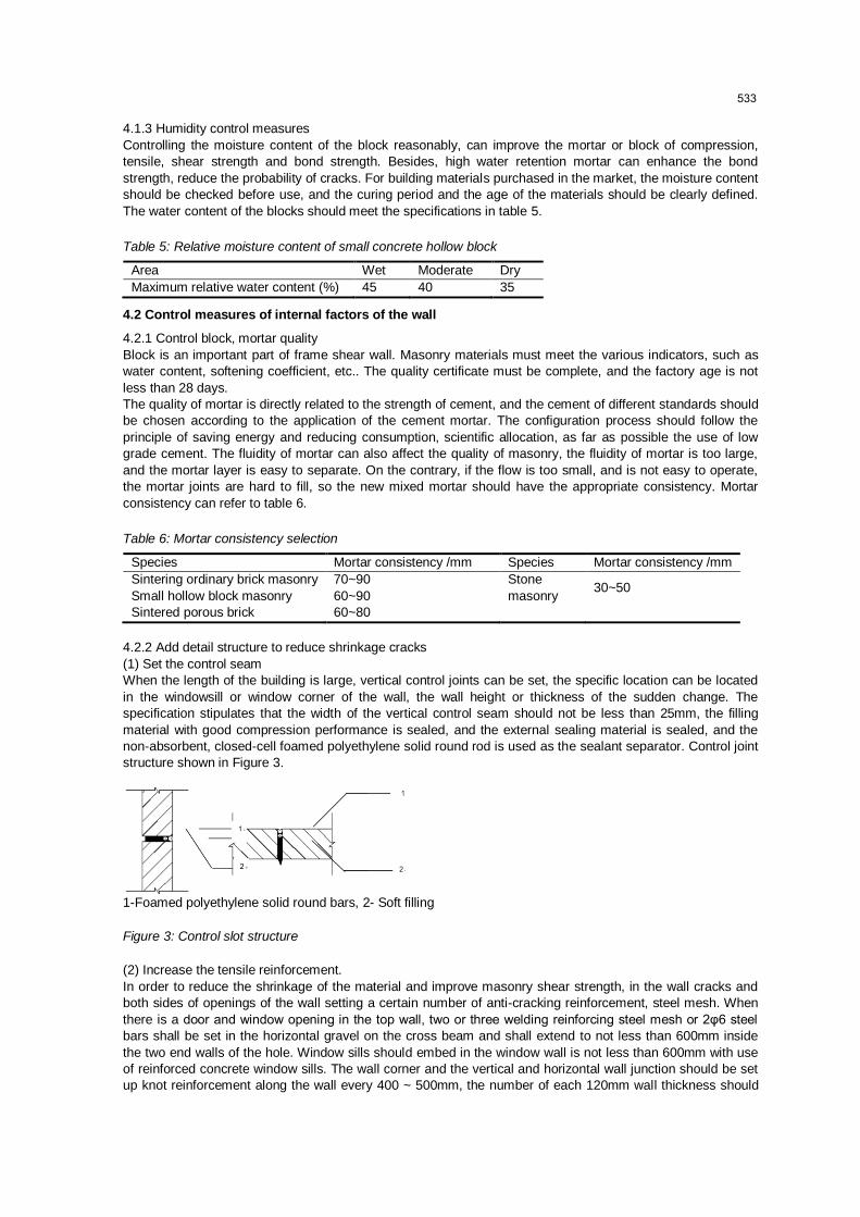
(1) Set the control seam
When the length of the building is large, vertical control joints can be set, the specific location can be located
in the windowsill or window corner of the wall, the wall height or thickness of the sudden change. The
specification stipulates that the width of the vertical control seam should not be less than 25mm, the filling
material with good compression performance is sealed, and the external sealing material is sealed, and the
non-absorbent, closed-cell foamed polyethylene solid round rod is used as the sealant separator. Control joint
structure shown in Figure 3.
1-Foamed polyethylene solid round bars, 2- Soft filling
Figure 3: Control slot structure
(2) Increase the tensile reinforcement.
In order to reduce the shrinkage of the material and improve masonry shear strength, in the wall cracks and
both sides of openings of the wall setting a certain number of anti-cracking reinforcement, steel mesh. When
there is a door and window opening in the top wall, two or three welding reinforcing steel mesh or 2φ6 steel
bars shall be set in the horizontal gravel on the cross beam and shall extend to not less than 600mm inside
the two end walls of the hole. Window sills should embed in the window wall is not less than 600mm with use
of reinforced concrete window sills. The wall corner and the vertical and horizontal wall junction should be set
up knot reinforcement along the wall every 400 ~ 500mm, the number of each 120mm wall thickness should
533

not be less than 1φ6 or welded steel mesh, embedded in the length of the corner from the wall or junction ,
Not less than 600mm on each side. From the corner of the wall from the buried length or the intersection of
counting, each side of must not be less than 600mm.
4.2.3 Improve the quality of gray seam
The quality of masonry wall is directly affected by the quality of gray joint, which is controlled by the fullness
and thickness of mortar. Masonry mortar wall must ensure full, horizontal and vertical. Thickness of the gray
seam should be controlled between 8 and 12 mm and fullness of not less than 80%.
5. Conclusion
This paper analyzes the concrete causes of cracks in the frame filled walls of steel reinforced concrete
structures caused by the temperature variation, uneven settlement of foundation, the influence of humidity and
the strength of mortar, putting forward the concrete control measures, such as building insulation layer and
setting expansion joints, to prevent the occurrence of cracks. The conclusion can provide a reference for the
construction of steel - reinforced concrete infill wall.
Reference
Bo M., 2009, Analysis and prevention of common cracks in masonry structure, Inner Mongolia Water
Resources, 1, 30-31.
Cao C., 2012, Study of brick concrete structure wall crack prevention, China Science and Technology Review,
36, 264-264.
Chen Z., 2010, Anti - cracking measures of autoclaved aerated concrete masonry wall and stucco layer,
Comprehensive utilization of fly ash, 3, 33-37, DOI: 10.3969/j.issn.1005-8249.2010.03.013.
Gao L., 2011, Technical specification for building structure of steam and aerated concrete block masonry, Wall
Materials Innovation & Energy Saving in Buildings, 10, 26-30, DOI: 10.3969/j.issn.1006-9135.2011.10.038.
He S., 2010, Cause and prevention of the cracks in frame filling wall of aerated concrete block, Brick & Tile
World, 4, 47-49, Doi: 10.3969/j.issn.1002-9885.2010.04.017.
Khankhaje E., Salim M.R., Mirza J., Hussin M.W., Ho C.S., Rafieizonooz M., 2017, Sustainable pervious
concrete incorporating palm oil fuel ash as cement replacement, Chemical Engineering Transactions, 56,
445-450, DOI: 10.3303/CET1756075.
Wu X., 2012, Ground treatment method for uneven settlement of building, Journal of Langfang Teachers
College, 12(2), 67-69.
Yan M., 2011, Causes and prevention of cracks in frame shear wall structure, Zhongzhou Construction, 19,
68-69.
534