cathy and phil cobbin's rv7a project 3q2004 photo...
TRANSCRIPT

Cathy and Phil Cobbin's RV7A Project
3Q2004Photo Log
1 of 62
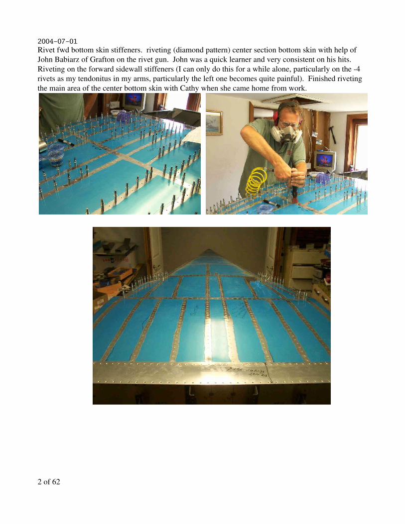
2004-07-01Rivet fwd bottom skin stiffeners. riveting (diamond pattern) center section bottom skin with help of John Babiarz of Grafton on the rivet gun. John was a quick learner and very consistent on his hits. Riveting on the forward sidewall stiffeners (I can only do this for a while alone, particularly on the 4 rivets as my tendonitus in my arms, particularly the left one becomes quite painful). Finished riveting the main area of the center bottom skin with Cathy when she came home from work.
2 of 62

2004-07-02Primed center side skin to rear tail section interface on the tail skin which I overlooked doing when the tail assembly parts were primed. Riveted the forward bulkheads between the main spar bulkhead and the firewall and the F719B stiffeners. Deburred, filed and primed the interior cabin sheet metal.
3 of 62

2004-07-03Primed bottom skin surface which I fill fit the flap from the side skins (the rolled skin). This area is fitted opposite the plans with the side skin exposed. This will increase drag but I figured if the plane cannot be hangerd the other way of fitting the sheets leaves you with water coming down the side skin and getting inside the fusalage at the side skin/bottom skin joint. Took check ride for private pilot's license in winds 9 knots gusting to 21...piece of cake. Examiner was Jack Fern the head of the State of NH Aeronautical Dept. Riveted the forward skin bottom stiffeners. Alligator squezzed the rivets ont he forward edge the firewall on the bottom skin. ROLLED OVER THE CANOE! which turned out to be a one person easy job if you think it through and do it in two stages. Roll onto the side...then roll upright.
4 of 62
5 of 62

2004-07-04Clecoed top skins in place to preview future workand located and various parts to scope out fit. Sure glad I waited to drill F721B rails to the main longeron as they would have lived a hard life on the wood during assembly and fitting of the canoe and I doubt I would have had them dead nuts on location fore/aft on the main longerons. I also did not fully bend the longerons on this area as I elected to hold off to see how things finally fitted up. Needed and 1/8 to 3/16 max adjustment in bend of the main longeron.
6 of 62

2004-07-05Fabricated tooling to adjust final bend in main longeron to fit with the F721B rails, got fit to within 1/64 max runout will try to get rid of that when I do the drilling.
7 of 62

2004-07-07Drilled F721B's to main longeron.
8 of 62

2004-07-09Milled square hole in F757's and cleco'd back on fusalage. Fabricated 1/4 to 3/8 drill adapter so I can use the air drill with unibits...particularly since I forget some 5/8 holes in the aft bulkheads for the rudder cables... Decleco'd the top skins in the rear. Layout of location for shoulder harness mounts. Programmed and drilled holes for F695 gussets, probably the flimsiest set up of my life but it worked. Drilled the F695 gussets into place on the fusalage. Dimpled and started riveting on F728A upright which supports the bellcrank. Cleco's F787 in place for later drilling with skin on. Drilled F656 Gussets (4). Scoped out setting the rear deck in place will double check leveling tomorrow before drilling it in place.
9 of 62

2004-07-10Reviewed Brian Mayette's email pointing out problems in drilling and riveting the F721C and F721D attach angles for the instrument panel. He noticed I had the F721A fwd canopy decks cleco'd on in a photo I emailed out to freinds. Apparently the parts are a nightmare on quickbuilds for drilling and riveting. Validates why I "preview" future assembly and fab work to try to avoid problems. Checked remaining sheetmetal part inventory for where on the fusalage they go, what drawing numbers reference/show the part...and most importantly, which ones have to have modifications machined/sheared into them. Made up some shims and leveled the fusalage fore and aft. I cannot detect any twist using a carpenters level between the F705 (measured with level accross top of bulkhead) and the rear deck, nor the firewall and the rear deck (placing the level under the bottom of the firewall lower edge for a reference). Drilled aft deck to main longerons. Caught a major alignment bobo due to not having riveted the top most rivets yet in the bulkheads/skins. Riveted the skin up to and including the main longeron in the rear and refitted aft deck. The hole on the left side just in front of the F711C bar on the F711 bulkhead was misdrilled the first time too close to the edge and after riveting the side skins to tightnen the fit against the bulkhead the actual hole location on the deck if drilled would produce a oval hole one diameter by two diameters in cross section. Am electing to skip any hole work on this hole and leave it alone. The manual is a tad vague as to when to fabricate, locate and drill the spacers that go under the deck: i.e. The F710C and F711E spacers. Accordingly, I only drilled the main longerons/deck for now and have to fab the spacers before drilling the their respective holes. Drilled the F709 the F714 aft deck. Filed rear top skin edges and stripped insulation and cleco'd them onto fusalage for drilling.
10 of 62

11 of 62

2004-07-11Drilled F774 and F775 top skins to bulkheads and J stringers. Riveted sides of front edge of firewall.
12 of 62

2004-07-12Riveted misc. rivets on side skins after double checking which ones can be done now for a tip up fusalage. Did final drilling for F757T mods for tip up at F705 rear spar bulkhead. I may actually wait until the roll bar is fully fabricated and fitted before doing any further riveting in this area. Deburred parts to get ready to dimple/prime; primarily the current batch of drilled gussets.Drilled rudder pedal parts. Scrapped two F6117C angles and had to make a two more. Very tedious day.
13 of 62

2004-07-13Deburing rudder and varios gussets. Primer'd the parts after a white gas wipe and schotchbriting of surfaces. Visit in the afternoon from EAA technical councilor to look over work. We discussed et al engines and were both in agreement airplains should have airplane engines...ala Lycoming or Superior Air Parts!. Discussed rivet hole issue for one hole on rear deck. Sounds like my idea of just leaving the one hole blank is probably the way to go (misdrilled hole one full diameter out of alignment because I forget to rivet the sides fully and lock the longeron position...dodo). Riveted rudder pedal assemblies together alligator squezzer. You can do the pedals with the squezzer if you pay attention to the order of riveting and put the brake side plates on last.
14 of 62

2004-07-14Riveted stiffeners onto F706 and F707 Bulkheads. Deburred and rivetted the F695 gussets at the firewall. Made another anvil for the alligator squezzer to rivet the AN4704 rivets to the F601J angles. Went up one rivet length from 7 to 8 in light of the spacer I added to the assembly rather than notch the two floor central floor stiffeners. Didn't use anvil (1/16) to big at 5/16 but spacers on existing tooling worked well and an alligator squezzer is ideal for setting these rivets as a gun/barr is problematic and would require a double offset tool and a squezzer doesn't work. Collected materials for fabrication of spacers etc for rear deck and checked other prints for types of materials needed to fabricate final set of parts for front fusalage etc. to make sure I had materials and didn't inadvertantly saw my self into a problem. Assembled Rudder pedals and brake cylinders.
15 of 62

2004-07-15Machined & drilled in assembly F711E down elevator stop, and F0710C spacer for empenage attach. Machined F712D up elevator stop. Made and drilled the F653B spacer and drilled the F635 bellcrank assembly. Machined the F703B angle, the small cnc program to do the 15 degree slots worked great with a 1/8 inch end mill. Cut material for F721C's, F743B, F703C, F768D, and F768C, F721D, and F793 angles/brackets. Primarily worked with little cnc programs to do drilling location, milling notches etc. Layout of hole locations for VA107 on firewall.
16 of 62

2004-07-16Trimmeed F644 into L&R varients. Trimmed F643. Wild goose chase for F697 to do trim work shown on Dwg 24A...based on parts index looks to be supplied as part of finishing kit. Set up and used brake to bend F768B's and F768A.
17 of 62

2004-07-17Woody visits the fusalage.Fabricate milling jig for F-768C Seal Support Angle(s) and fabricate same. This jig works with two cleco's to hold the piece and you then drill/mill the spacing as you go.
18 of 62

2004-07-18Fabricate mill jig and mill F-793 Vent Brackets. This is a good example of where the CNC system shines, this would be very tricky to do by hand.
19 of 62

2004-07-21Fabricated first of series of drill jigs for drilling the hinge material for use in attachment of the hinge material to the seat back and seat mounts. This jigging allowed for drilling the hinge then taking the jig and placing it against the floor and drilling the floor holes etc.
20 of 62

2004-07-22Test fitup/clecoing of seat back after drilling with locating jig.
21 of 62

2004-08-01-oshkosh
22 of 62

2004-08-04Brought a deep throat yoke back from Oshkosh so I could finally do some hard to reach rivets like these here on the nose of the horizontal stabilizer.
23 of 62

2004-08-05 Deburing and fitting upper fuselage parts. Drilling and fitting the F-771 Forward Skin gets a bit tricky as you have to make sure you have all the springback out of the firewall etc. This is a major torsional strength adder to the overall fuselage.
24 of 62

2004-08-06 riveting the F-709 bulkhead in place. Also rivetted the F-635 Bellcrank Assembly with the alligator squezzer.
25 of 62
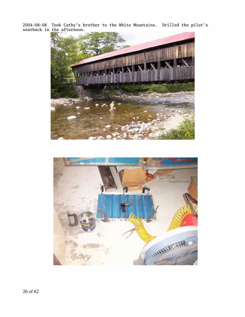
2004-08-08 Took Cathy's brother to the White Mountains. Drilled the pilot's seatback in the afternoon.
26 of 62
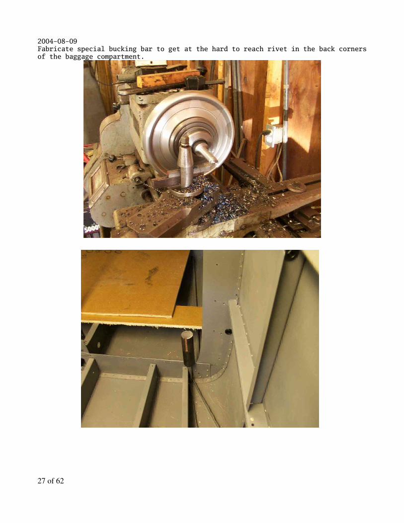
2004-08-09 Fabricate special bucking bar to get at the hard to reach rivet in the back corners of the baggage compartment.
27 of 62

2004-08-101. Begin riveting the aft top skin F-774
28 of 62

2004-08-11Drilling the hinge to the back of the pilot's seatback. Squeezing rivets on the baggage compartment ribs to the F-708A bulkhead.
29 of 62

2004-08-12 Using one of our drill jigs to drill the holes for the seat back attachment points into the F-742's. Finishing up some hard to get at rivets on the bottom of the canoe...Cathy the happy rivet gun driver on the floor.
30 of 62

2004-08-13 rivetting the hinges in place for the floor.
31 of 62
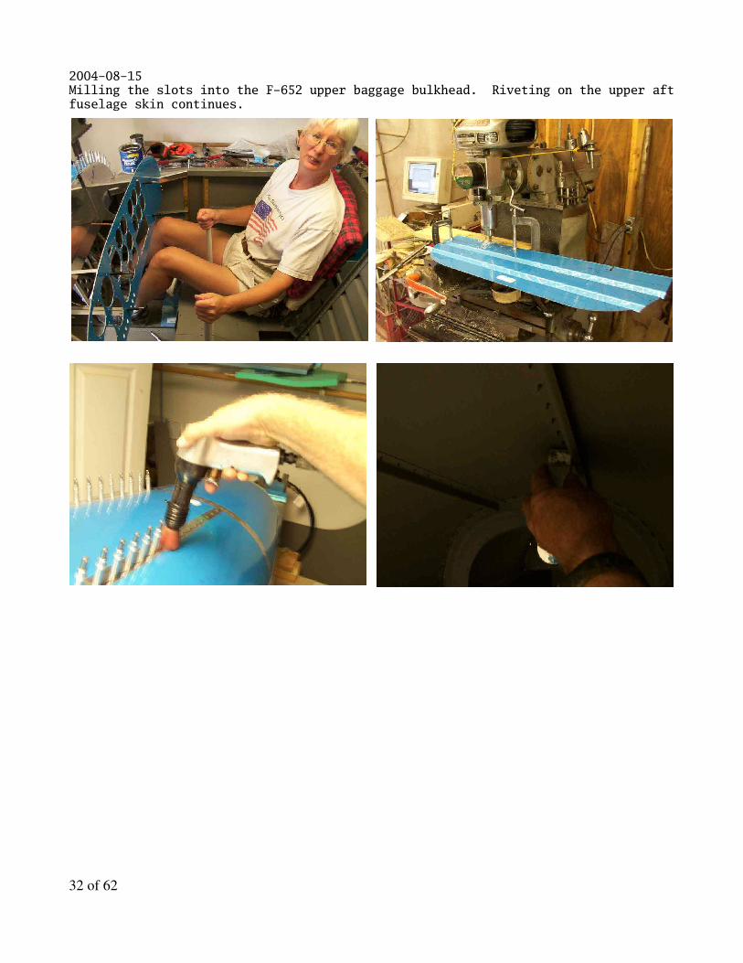
2004-08-15Milling the slots into the F-652 upper baggage bulkhead. Riveting on the upper aft fuselage skin continues.
32 of 62
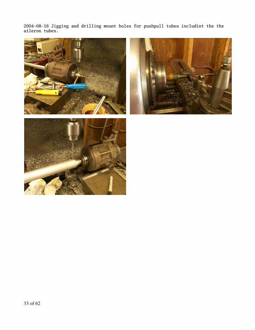
2004-08-16 Jigging and drilling mount holes for pushpull tubes includint the the aileron tubes.
33 of 62

2004-08-17 Fabricate flap hardware and ream out the flap attachment hole in the weldment to size. In addition to machining the Z Brackets for the tunnerl cover F-766B, F-785B, F-766C, F-767, F-741A's tunnel support brackets.
34 of 62
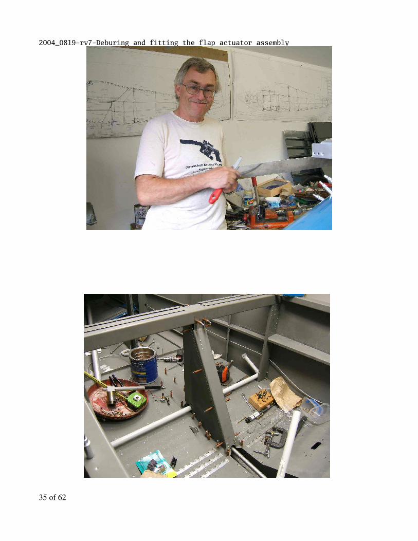
2004_0819-rv7-Deburing and fitting the flap actuator assembly
35 of 62

2004_0820-rv7-Fabricate the optional tie down bolt holder from scrap and drilled the F-749 forward baggage compartment side cover.
36 of 62

2004_0821-rv7-Checking fit up of instrument panel.
37 of 62

2004_0826-rv7-Drilling the flap motor assembly. Begin demolition recon on west wall to scope out putting an 8' window there...disaster...hillbilly construction. Note how there is only one vertical member in the wall...it's holding up the roof beam at the top of the roof.
38 of 62
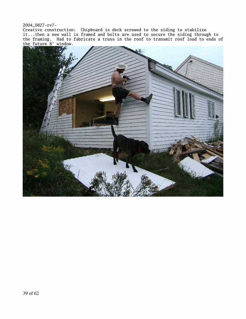
2004_0827-rv7-Creative construction: Chipboard is deck screwed to the siding to stabilize it...then a new wall is framed and bolts are used to secure the siding through to the framing. Had to fabricate a truss in the roof to transmit roof load to ends of the future 8' window.
39 of 62

2004_0828-rv7-Sawing our way out of the house for a 6' sliding glass door so we can get the fuselage out of the house.
40 of 62

2004_0829-rv7- Getting ready to move the fuselage, good time to start on the landing gear work.
Okay, no more goofin' off.
Now that we cleared some of the rubble out of the room it doesn't look like we got hit by a mortar, so I started fitting the the landing gear to the fusalage so I can make up a set of temporary wheels to move it to the garage.
Here I'm running a 5/16" ream to match drill/ream the hole for the left main gear to the weldment which is bolted to the fusalage.
41 of 62

2004_0830-rv7- Die ground the hole for the landing gear mount as it exits the fuselage. This takes a lot of patience to open up so as not to over do it.
42 of 62

2004_0831-rv7- Drilling for mounting the landing gear.
43 of 62

2004_0901-rv7- Ready to roll...out of the house.. This double truck using a 2x4 worked great the double wheels make it easier to move over run-uneven terrain...noticed a picture a while back of an army observation plane from WWII fitted with wheels like that...
The chick gets out of it's egg... Sort of. Took a little jockeying around, but I finally got the fusalage with it's 7' 6" main gear leg stance though a 6' opening.
The fusalage is now in the garage and after we clean up the disaster in there we'll start scoping out rigging for wings and empenage, then take it all apart and put the fusalage back in the house for the winter.
44 of 62

2004_0903-rv7- Bird in a new nest: Set up fuselage on saw horses and start leveling and fitting the horizontal stabilizer.
Let the rigging begin!
Now all I have to do is clean the garage a little... That swamp should keep the alligators fed for while!
45 of 62

2004_0904-rv7- Bought some hardware store bolts and bullet nosed the ends to fit the wings. I am only going to use the high strength bolts once: on final assembly.
The chick sprouts wings for the first time!
The big question comes down to wether or not the spars will fit in there respective sockets! The right wing was done first and it was the hardest.
I'm probably going to rent a surveying transit to go over the leveling one more time before I comit to drilling the rear spar which sets the wings critical angle of incidence.
Now for lots of fiddling around and checking and rechecking the alignments... Building an airplane... What a hoot!
46 of 62

2004_0905-rv7-foxOkay so some days I don't take any plane work pictures... This young fox is a really cute... Of course when it gets bigger and takes a hankerin' for chicken, it's going to be a less freindly encounter.
She's standing in the gap in the stone wall on the north boundary of the property. I've seen her before with another sibling.
47 of 62
2004_0906-rv7- Just getting started on the metrology work-out to make sure the wings are not swept (forward or aft) and to set the wing incidence. I've got to get some string and make up another plumb bob to check the leading edge of the wing for sweep. The left wing looks to be set to the required incidence measurement (3 inches) between the front and rear spars to within a 1/64 of an inch i.e. about 0.015 inch.
I'm planning on making a drill jig to clamp the rear spar and associated bulkhead together and make up a series of drill bushings so I can get the hole (a) straight, (b) the right diameter, and (c) with the correct and critical minum edge clearances...
48 of 62

2004_0909-rv7- Van's specs using a level to set the wing incidence with a gauge measurement off the rear spar. A square can also be used to double check and Found it's hard to discern a 1/32" of travel on the level but's a snap to resolve down to 1/64 inch with the square.
Here are two shots showing a method for setting the specified angle of incidence for the wings.
The plans call for using a level, but I found this method of using a square allowed one to dial in the specified parallellism between the level with a 3" gauge block and the main longeron by using a 2x4 and a truck jack to dial in the incidence position to within less than 1/64" inch total deviation between both wings...
Trust me... I ain't that good using spirit levels even if I take my glasses off and eye ball the level glass up close and personal.
There is so far only one little sticking point... The wings are swept forward by about 1/8 inch. I've sent an email to customer support at Van's to check the acceptance of this before I commit to drilling the attach hole in the rear spars.
Meanwhile, as I await information from Van's, I'll work on a drill jig and drill bushings to assure the hole is set safely within edge clearance requirements and is square to the spars.
Man, is the humidity high... The garage floor looks like I took a hose to it!
49 of 62
2004_0910-rv7-Van's customer support got back to me by this morning... Those guys have excellent support... They said up to an inch of sweep would probably not be a big deal... If I want the 1/8 off I have to pull the wings off and file the end of the spar back... Which I am not going to do.
Instead, made up drill jig and bushings to drill and ream the rear spar hole. Here are some photos of the jig/bushing/ream clamped into position, an indication of where the center of the hole will be, and an overall collection of the jig and tooling parts and my chicken scratch sketch which started things off.
I'll think about it and double check things probably tomorrow before I commit to drilling and reaming the hole in the rear spar/fusalage attachment.
50 of 62

2004_0911-rv7-Drilled and reamed the rear spar to fusalage attachment hole with my drill jig and bushings. Very nice surface finish on the hole. Also worked out the fitting-up of the right flap.
I used the first of two methods suggested by Van's to secure the flap hinge rod: Drill a hole slightly off center through the aeleron bracket, and then when you finish pushing the long pin in, place it so it pops through the hole, and the off center location keeps the pin from coming back out on the outboard side... And the fusalage is in the way on the inboard side.
Working out the clearance on the actuator pushrod for the flap took a while, the plans are... Sort of... Vague... On the details.
51 of 62
2004_0912-rv7-Some days you just have to work with whatever space you can scrounge up.
Finished the left flap attachment details and preliminary hook up of the push tubes for the ailerons. I waited to finish fitting up the elevator to the horizontal stabilizer until I had the fusalage and wings pretty much set.
It works out better to wait and do the final drilling of the bellcrank weldment on the elevators... Then, trim the area where the counter weights swing to make sure both elevators stay in trail together with no screw-ups on hinge hole drillings, etc.
52 of 62

2004_0922-rv7-
53 of 62

2004_0922-rv7-After a trip to Oklahoma and Texas, and cleaning up some of the rubble in the garage, I've finally had a chance to start machining details and laying out the holes to mount the horizontal stabilizer to the airframe. You don't want to mis-drill these key holes that have to tie into the main longerons.
54 of 62

2004_09_23-rv7Using my CNC mill for some extra details.
Rather than chance clamping the plate that attaches the vertical stabilizer at the front with c-clamps, and inviting the obvious mis-alignment problems, it works out better to scale the pilot hole (1/8) pattern on the horizontal stabilizer (2-3/8 x 3) and use the mill to drill pilot holes in the attachment plate.
Then it's a snap to just cleco the plate in place and run a drill through the holes, one at a time, to size them for the bolt.
The first shot is the best screen shot I've been able to get of the software I started to write as curiosity project when I was recuperating from a little cardiac adventure back in 98. I've used the software quite a bit on this project and actually dusted off the wormy source code to straighten out some bugs with milling circles.
55 of 62

2004_0924-rv7-Boy, these windows are heavy! Installed the sliding doors myself, but had to wait for Cathy to come home to put the 4x8 window in.
Didn't get any pictures of the plane today, but I moused around for over an hour getting the vertical stabilizer... err... vertical... and clamped into position. Now to work out how to drill the bolt holes, etc.
Based on the effects I saw today, the slider and 4x8 window should be a sunroom hit in the winter, so the fusalage and I expect to have to share some space with my motherinlaw's knitting, sewing, and the occasional bread rising, this winter.
Now all I have to do is get the wiring, drywalling, and miscellaneous finishing done before the snow flies. That includes getting the plumbing for the fuel lines done before I take everything back apart and reload the fusalage into the "room with a view" for winter.
Need to saw up a couple cords of wood yet, too!
56 of 62

2004_0925-rv7-We're getting the windows and doors buttoned up... and meanwhile back at the ranch...
Have the rear spar of the vertical stabilizer drilled in place. Tomorrow I'll drill the holes for the mount on the forward spar of the vertical stabilizer, then it's time to debur, prime, and rivet some of the parts.
I thought Cathy's technique for hammering nails was quite interesting...
Haven't a clue how I would have drilled the holes in the vertical stabilizer rear spar without a right angle attachment (in this case to my dremel tool). There isn't a lot of room to move your paw around in.
57 of 62

58 of 62

2004_0926-rv7-Have the tail feathers mounted. Still have mounting details to work out and drill.
59 of 62

2004_0928-rv7-Interesting start to the day... I went to start the computer - which runs a real time linux kernal - to do some milling/drilling or the rudder stop brackets. Sure was a nasty surprise to see it wanting to boot into Windows 95!
After tearing the machine apart, I found it was booting off an old slave drive which had Windows 95. Sounds like the master drive is spinning up a little slow these days, so I backed up all the numerical control programs to my main machine in the house.
Whew! Sure killed half the day.
Got the rudder stops milled and drilled and all the control surfaces have been test fitted. I only have the aeleron motion stops to set on the wings. It took me about an hour to figure out how to drill the inboard pair of holes on the horizontal stabilizer.
I finally resolved to run a 3/32 aircraft drill as a pilot hole and then run the 3/16 drill using an airdrill from inside the fusalage, and drill back out once I had a pilot hole for location. Sure was a bit tight getting both paws, an air drill, and the air hose in the tail cone!
60 of 62

61 of 62

2004_0929-rv7-I forgot to grind off the center hinge eyes for mounting the seats when it was easy to do... So now I get to do it the hard way. Also, I finally broke down and abandoned the taped shut chopstick method for holding washers and ground up a special pair of plyers.
To take up the slack in the control column you have to slide thin washers into place, which becomes a real wrestling match! Van's says you have to put in a 5 degree bend on the fuel tank attachment bracket. How you would do this without an arbor press is a mystery to me... I really really really don't like using a setting block and the hammer and vise method, whenever I can avoid it.
Now for some of the finer points on running fuel and brake lines...
62 of 62