catalyst manufacturing science and engineering …cbe.rutgers.edu/pdf/brochure.pdfcatalyst...
TRANSCRIPT
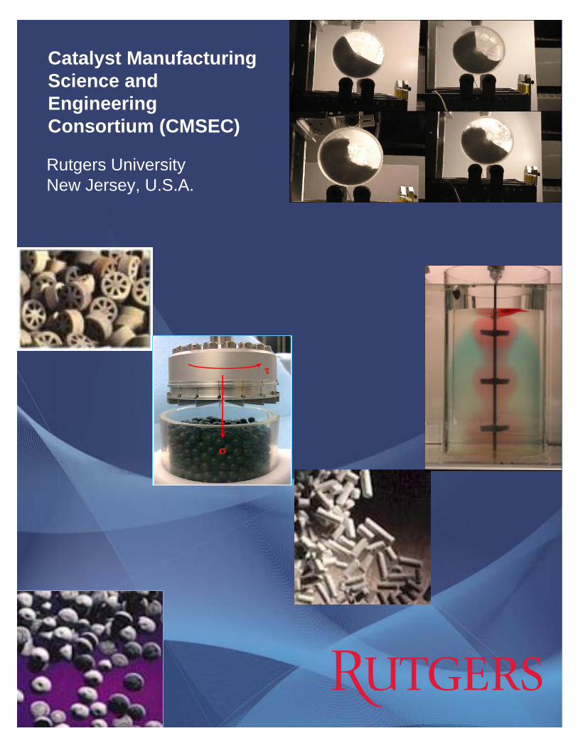
Catalyst Manufacturing Science and Engineering Consortium (CMSEC)
Rutgers UniversityNew Jersey, U.S.A.

While a large segment of the US industry, including the petroleum, chemical, pharmaceutical, automotive, and energy industries makes and/or uses catalysts, there has been no academic program focusing on the operations required to make catalytic materials. Thus, catalyst manufacturing processes are often designed relying on empiricism, leading to uncertain/sub-optimal processes, decreased quality, and increased cost. By combining the substantial level of expertise in particle technology, optimization, multi-scale simulation, catalysis and molecular modeling available at Rutgers, we are developing and promoting science-based methods for designing and optimizing catalyst manufacturing methods and processes such as impregnation, drying, slurry mixing, extrusion, calcination, etc. This is integrated with a number of educational activities including research training of undergraduate students, graduate students and postdoctoral fellows in the area of Catalyst Manufacturing. A combination of experiments and computer models has been used to improve the understanding and performance of the unit operations used to make catalysts. This knowledge, and the resulting methods and practices, have been transferred to Industrial partners to help transform this important segment of the global economy into a science-driven enterprise. The specific goals of the consortium are: • To create a world-wide prime Center of
Excellence in catalyst manufacturing research.
• To enhance fundamental understanding of catalyst manufacturing operations.
• To develop new technology for efficient catalyst manufacturing.
• To provide a research, development, and education resource for industry.
The consortium was founded on October 1, 2003. The Rutgers faculty that are currently participating in the consortium and their expertise areas are: Benjamin J. Glasser (drying, fluidized beds), Johannes G. Khinast (drying, catalysis), Fernando J. Muzzio (particle technology, mixing), Arthur Chester (industrial liaison, catalyst preparation), William Borghard (calcination, catalyst preparation), Silvina Tomassone (impregnation, interfaces), Alberto Cuitino (particle technology,
compaction), and Rohit Ramachandran (particle technology, agglomeration). The annual fee for membership in the consortium is $35,000. These are unrestricted funds for research. The consortium members (companies and faculty) meet every 6 months (October and March) for project reviews. In the October meeting, the consortium decides on continuing with current projects or starting new projects. Where consensus is not possible, a vote is taken, with each company getting one vote. Copies of the slides from the talks at the consortium meeting are made available to the consortium members. In addition, each project provides a written report on progress every six months. A list of possible manufacturing operations of interest to the consortium is given below: Powder blending, Powder sampling, Calcination, Slurry Mixing, Pellet compaction, Roller Compaction, Powder segregation, Catalyst drying, Non-Newtonian Liquid Mixing, Powder Flow/Handling, Multiphase Flow/CFD, Dispersion of solids, Impregnation, Mulling, Extrusion , Nano-templating, Fluidized bed coating, Granulation, Catalysis, Spray Drying, Atomization, Flash/Rotary Drying/Calcination, Plow-shear mixing, Liquid-Solid Separation (Filtration/Flocculation), Precipitation Catalysts. Projects that are currently funded by CMSEC are: • Impregnation of Catalysts • Drying of Supported Catalysts • Calcination • Powder Flow, Handling and
Characterization • Sensing of Mulling Operations Projects that have been funded by CMSEC in the past include: • Powder Segregation • Mulling/Extrusion of Catalyst Supports • Slurry Mixing • Continuous Powder Blending A description of projects that have been funded by CMSEC follows.
Rutgers Catalyst Consortium since 2003
Current and Past Industrial Members: Albemarle Chevron Haldor Topsoe Exxon-Mobil BASF Grace Evonik UOP Johnson Matthey CRI/Criterion Inc.
Projects: • Impregnation of
Catalysts • Drying of
Supported Catalysts
• Powder Segregation
• Powder Flow, Handling and Characterization
• Calcination • Mulling and
Extrusion • Slurry Mixing • Continuous
Powder Blending
Rutgers Catalyst Manufacturing Science and Engineering Consortium (CMSEC)
Contact: Prof. Ben Glasser Tel: 848-445-4243 [email protected]

Impregnation of Catalysts
Catalyst impregnation is a crucial process in the preparation of industrial catalysts. In this process, metal salts or complexes are dissolved in a typically aqueous solution and contacted with a porous oxide catalyst support such as alumina (Al2O3) or silica (SiO2). During a contact time of typically 30-60 minutes the metal is adsorbed from the solution onto the high surface area support. The catalyst is dried and further pretreated to transform the metal from its precursor state into its active form. Generally, the process of impregnation is performed in rotating vessels with one or more nozzles that distribute the solution with the metal precursor into the catalyst support. The process is typically referred to as dry impregnation as the amount of liquid sprayed onto the catalyst bed is kept at a minimum, and thus, the bed continues to operate as a granular bed. The ability to control dry impregnations and establish effective models for large batches can significantly reduce the amount of time required per batch while simultaneously achieving a more homogeneous distribution of solution.
In this work, a combination study incorporating a series of experiments as well as particle dynamic simulations are performed using a double cone impregnator in order to obtain a deeper understanding of the mixing and impregnation mechanisms. A computational study is performed using the discrete element method (DEM). Commercial software (EDEM, DEMSolutions Inc.) is used to facilitate technology transfer. Algorithms are being used to allow for the
spraying of water droplets on a flowing powder bed and the allowance of catalyst support particles to absorb the water, thus increasing weight and density; Figure 1 shows an example of fluid spraying onto a powder bed. Furthermore, cohesive properties have been taken into account and allow for a linear increase as a function of maximum support capacity. Experimental techniques are used to validate computational models by measuring
water content as a function of time in specific spray zones. In addition, mixing experiments are performed to better understand the relationship between spray flow rate and its effect on the catalysts bed distribution; an example is shown in Figure 2. The main goals of this project are to establish 1) how mixing and flow are affected when the particles have a certain degree of moisture or are saturated with liquid, 2) whether the liquid is homogeneously distributed into the powder bed and 3) the extent and distribution of dead zones for a given impregnator configuration and 4) to establish a scalable model that can be quickly applied to impregnation processes for optimal mixing and liquid distribution.
Drying of Supported Catalysts
Supported catalysts are essential components in a variety of industrial processes, ranging from catalytic converters to production of new drugs. The performance of a catalytic process is intimately related to the catalyst design - uniform, egg-yolk, egg-shell and egg-white metal profiles. It is generally believed that the metal profile is controlled by the
Figure 1: Particle dynamic simulation of double cone impregnator. A fan shaped spray pattern is shown.
Figure 2: Experimental impregnation study using 3 x 6 mm alumina pellets dyed for a concurrent mixing/impregnation study.

conditions that are applied during impregnation where the metal contacts the solid support for the first time. However, experiments have shown that drying may also significantly impact the metal distribution within the support. Therefore, to achieve a desired metal profile we need to understand both impregnation and drying. Controlling the drying conditions can enhance catalyst performance.
The goal of this project is to develop a fundamental understanding of unit operations during catalyst preparation, and predict, control and optimize metal distribution and dispersion of supported catalysts. Therefore, we can provide our partners with efficient tools to monitor and control the final quality of supported catalysts. In this work we have developed a theoretical model for drying which we have validated experimentally. In this model, we have taken into account heat transfer from the hot air to the wet support, solvent evaporation in the support, convective flow towards the support external surface due to the capillary force, and metal diffusion and metal deposition due to adsorption and crystallization (see Figure 3a). In general, the convective flow is the main driving force to transport the metal component and the solvent towards the support external surface (t=500s in Figure 3b), while the back-diffusion causes metal to transport towards the support center (t=1000s in Figure 3b). Experiments have been carried out to measure the distribution and dispersion of metal in catalyst supports in order to validate our modeling work. In Figure 3c, the metal profiles after drying are plotted from the support center to the surface for Ni/Alumina catalysts, where symbols represent experimental data and solid lines represent simulation results. It is clear that a nearly uniform distribution is observed for low drying temperature while egg-shell profiles can be greatly enhanced with increasing the drying rate. In this project, we have examined the distribution and dispersion of Nickel, Copper, Barium, and/or Palladium on Alumina and Silica. We are interested in investigating the importance of the physical properties of the solid support (porosity, pore size distribution, particle size) and liquid solution (pH, ionic strength, initial metal precursor
concentration), and the nature of interactions that exist between the dissolved metal and the solid support (physical adsorption, crystallization, ion exchange, film-breakage, pore-blockage) on the distribution and dispersion of the active metal.
dispersed gas (hot gas + vapor solvent)
precipitatedor adsorbed
solute
solidsupport
convectiveflow
(capillary flow)dissolved solute
(salt or metal)
back-diffusion
solventevaporation
heatsupplied by the hot gas
liquid phase(solvent +metal)
dispersed gas (hot gas + vapor solvent)
precipitatedor adsorbed
solute
solidsupport
convectiveflow
(capillary flow)dissolved solute
(salt or metal)
back-diffusion
solventevaporation
heatsupplied by the hot gas
liquid phase(solvent +metal)
(a)
t=100s
Metal Profile after impregnation
t=0st=100s
Metal Profile after impregnation
t=0st=500s
End of dryingt=1000st=500s
End of dryingt=1000s
(b)
(c)
Figure 3: (a) drying mechanism, (b) simulation of the evolution of the metal distribution during drying, (c) comparison of simulation and experiments for drying of Ni/Alumina catalysts.
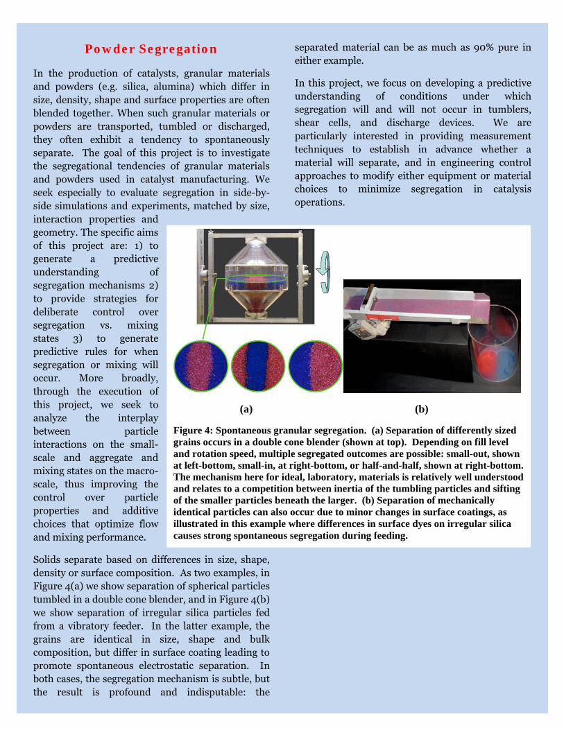
Powder Segregation
In the production of catalysts, granular materials and powders (e.g. silica, alumina) which differ in size, density, shape and surface properties are often blended together. When such granular materials or powders are transported, tumbled or discharged, they often exhibit a tendency to spontaneously separate. The goal of this project is to investigate the segregational tendencies of granular materials and powders used in catalyst manufacturing. We seek especially to evaluate segregation in side-by-side simulations and experiments, matched by size, interaction properties and geometry. The specific aims of this project are: 1) to generate a predictive understanding of segregation mechanisms 2) to provide strategies for deliberate control over segregation vs. mixing states 3) to generate predictive rules for when segregation or mixing will occur. More broadly, through the execution of this project, we seek to analyze the interplay between particle interactions on the small-scale and aggregate and mixing states on the macro-scale, thus improving the control over particle properties and additive choices that optimize flow and mixing performance.
Solids separate based on differences in size, shape, density or surface composition. As two examples, in Figure 4(a) we show separation of spherical particles tumbled in a double cone blender, and in Figure 4(b) we show separation of irregular silica particles fed from a vibratory feeder. In the latter example, the grains are identical in size, shape and bulk composition, but differ in surface coating leading to promote spontaneous electrostatic separation. In both cases, the segregation mechanism is subtle, but the result is profound and indisputable: the
separated material can be as much as 90% pure in either example.
In this project, we focus on developing a predictive understanding of conditions under which segregation will and will not occur in tumblers, shear cells, and discharge devices. We are particularly interested in providing measurement techniques to establish in advance whether a material will separate, and in engineering control approaches to modify either equipment or material choices to minimize segregation in catalysis operations.
(a) (b)
Figure 4: Spontaneous granular segregation. (a) Separation of differently sized grains occurs in a double cone blender (shown at top). Depending on fill level and rotation speed, multiple segregated outcomes are possible: small-out, shown at left-bottom, small-in, at right-bottom, or half-and-half, shown at right-bottom. The mechanism here for ideal, laboratory, materials is relatively well understood and relates to a competition between inertia of the tumbling particles and sifting of the smaller particles beneath the larger. (b) Separation of mechanically identical particles can also occur due to minor changes in surface coatings, as illustrated in this example where differences in surface dyes on irregular silica causes strong spontaneous segregation during feeding.

Powder Flow, Handling and Characterization
The goal of this project is to develop a fundamental understanding of granular and powder flow and shear properties, so that the behavior of intermediate and final catalyst products during manufacturing and processing can be predicted and controlled. The techniques and methods investigated in this project could provide our partners with valuable tools and ideas to efficiently design and scale catalyst manufacturing processes.
Powders and granular materials can be found in many processing steps in catalyst manufacturing; they exhibit a variety of flow patterns, and their state and behavior differs from application to application. Since there is a lack of fundamental understanding of powder behavior, multiple problems can be encountered during production, such as jamming of hoppers, sub-standard blending performance, and weight variability of final products due to segregation and/or agglomeration. Scale-up can also be a challenge, since the lack of constitutive equations for granular materials forces most scale-up efforts to follow the trial-and-error route. There are numerous methods to characterize the flow properties of granular materials, such as avalanching testers, fluidizers, shear cells, indicizers, density methods, angle of repose, etc.; however, most of them are application-specific, and it is not clear, how they correlate with each other or with process performance. For this reason, the use of most of these testers is restricted to a specific application, for which they were designed, and any attempts to apply the results of such experiments to a different application frequently result in process problems.
In this work, we have created a family of standard catalyst materials, spanning a wide range of flow properties from very cohesive to free-flowing. We then used the characterization equipment to investigate the flow properties of these materials and to determine the correlations between the
techniques. This project is also set to investigate the ability of the characterization methods to predict the powders’ process behavior by examining the flow from bench scale hoppers. The study has found that there is a discernible correlation between the measurement techniques (shown in Figure 5) in characterization of catalyst blends. We also confirmed that the generally accepted
characterization methods, such as shear cell, have range limitations, when evaluating extremely cohesive or very free-flowing powders and such methods are not always applicable in the case of unconfined flow conditions. It is also of interest to investigate how various material factors change the flow properties of the catalytic powders, such as presence of moisture or flow-modifying agents.
Calcination
Calcination is a thermal treatment process applied to ores and other solid materials in order to bring about a thermal decomposition, phase transition, or removal of a volatile fraction. Calciners can be of batch type as well as continuous type. Calcination is a crucial operation in catalyst manufacturing. Developing better process level understanding of this operation can significantly improve the quality of the end product as well as save energy and material costs. However due to the nature of the
(a) (b)
Figure 5: Images of (a) Gravitational Displacement Rheometer (GDR) and (b) shear cell module.
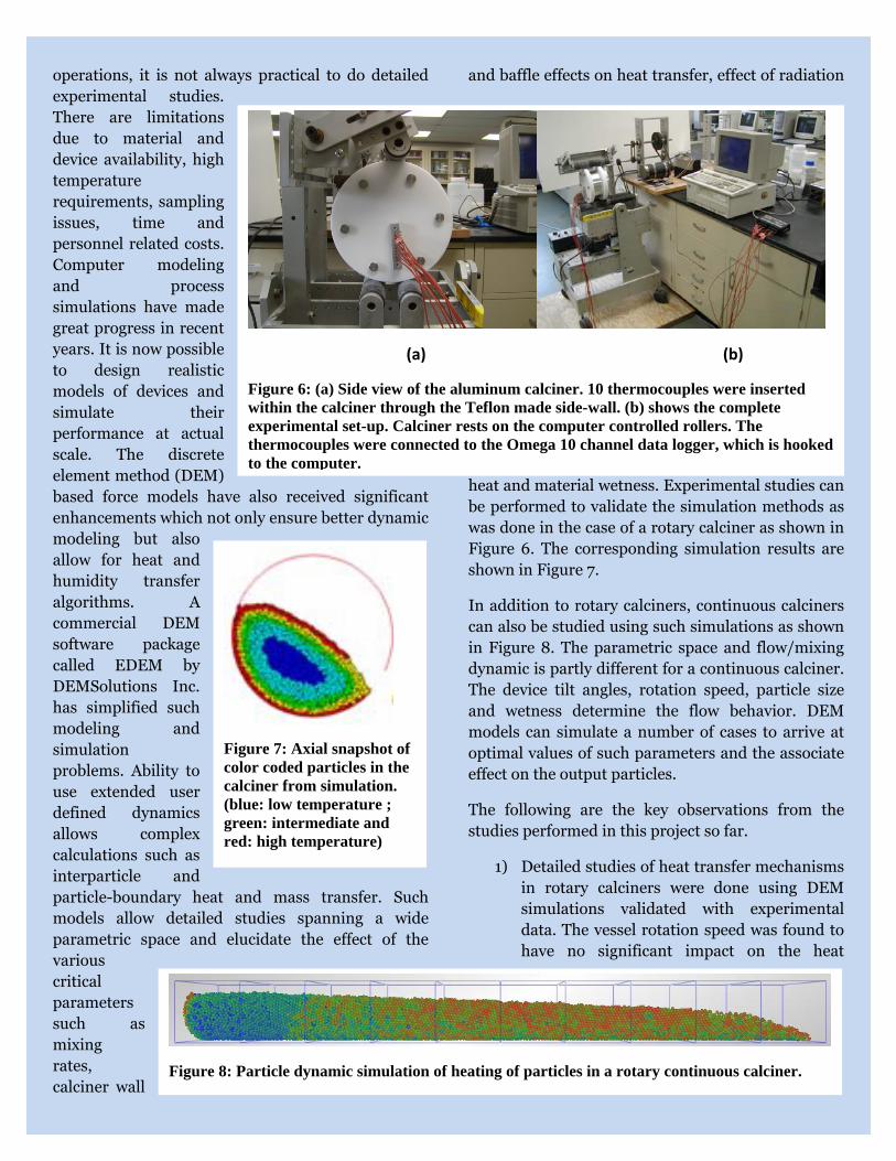
operations, it is not always practical to do detailed experimental studies. There are limitations due to material and device availability, high temperature requirements, sampling issues, time and personnel related costs. Computer modeling and process simulations have made great progress in recent years. It is now possible to design realistic models of devices and simulate their performance at actual scale. The discrete element method (DEM) based force models have also received significant enhancements which not only ensure better dynamic modeling but also allow for heat and humidity transfer algorithms. A commercial DEM software package called EDEM by DEMSolutions Inc. has simplified such modeling and simulation problems. Ability to use extended user defined dynamics allows complex calculations such as interparticle and particle-boundary heat and mass transfer. Such models allow detailed studies spanning a wide parametric space and elucidate the effect of the various critical parameters such as mixing rates, calciner wall
and baffle effects on heat transfer, effect of radiation
heat and material wetness. Experimental studies can be performed to validate the simulation methods as was done in the case of a rotary calciner as shown in Figure 6. The corresponding simulation results are shown in Figure 7.
In addition to rotary calciners, continuous calciners can also be studied using such simulations as shown in Figure 8. The parametric space and flow/mixing dynamic is partly different for a continuous calciner. The device tilt angles, rotation speed, particle size and wetness determine the flow behavior. DEM models can simulate a number of cases to arrive at optimal values of such parameters and the associate effect on the output particles.
The following are the key observations from the studies performed in this project so far.
1) Detailed studies of heat transfer mechanisms in rotary calciners were done using DEM simulations validated with experimental data. The vessel rotation speed was found to have no significant impact on the heat
Figure 7: Axial snapshot of color coded particles in the calciner from simulation. (blue: low temperature ; green: intermediate and red: high temperature)
(a) (b)
Figure 6: (a) Side view of the aluminum calciner. 10 thermocouples were inserted within the calciner through the Teflon made side-wall. (b) shows the complete experimental set-up. Calciner rests on the computer controlled rollers. The thermocouples were connected to the Omega 10 channel data logger, which is hooked to the computer.
Figure 8: Particle dynamic simulation of heating of particles in a rotary continuous calciner.

transfer at both low and high Froude number regimes. The fill level had a moderate effect on heat transfer, suggesting that higher fill levels might be effective in practice.
2) Average wall-to-solid heat transfer coefficient was estimated based on experimental observations for use in simulations.
3) The addition of baffles in the rotary calciner was found to have a significant effect on the heat transfer due to improvement in the mixing. Furthermore, heated baffles enhanced the calcination significantly as compared to adiabatic baffles.
4) Radiation from the calciner walls was found to have a significant effect on calcination. Walls with higher emissivity affected the average bed temperature as well as the distribution of temperature in the particle bed. Cohesion in the particle also had a significant effect on the temperature uniformity of the bed. In highly cohesive cases, the particle drying happened in two distinct time-separated regimes as opposed to linear drying in free flowing materials.
A short study on continuous calciners was performed. The effect of speed was found to be significant.
Mulling/Extrusion of Catalyst Supports
Mulling/Extrusion is one of the most efficient techniques for producing objects with constant cross section and with high symmetry such as rods, tubes, honeycomb structures and channels. The extruded products find applications in catalyst supports, heat exchanger tubes etc. Most catalysts used in the petrochemical and petroleum industries consist of metals supported on γ-alumina pellets or spheres. The γ-alumina is formed by calcination of boehmite (α-alumina monohydrate, AlOOH) at 500-550°C. Boehmite is one of the most widely used precursors
in the preparation of catalytic supports, high temperature ceramics and composites.
In this project, a laboratory high shear mixer was used to prepare the pre-extrusion samples, which were then extruded with a simple Carver press; powders and extrudates were characterized both prior to and after calcination as a function of mixing time by a variety of techniques, including FTIR, Powder XRD, high resolution porosimetry and paricle size analysis, among others. Not much literature is available with regards to the fundamental chemistry occurring during alumina mulling prior to extrusion using a high shear mixer. The purpose of the high speed granulation is to improve the properties of the feed powder. It can improve handling properties of a powder, reduce dust formation, eliminate segregation of two powders, improve powder solubility, and improve the extruded product properties-porosity and strength. Powder XRD line widths suggested that crystallite size was increasing during the high shear mixing operation, even though average particle sizes were significantly decreasing. Of particular interest, porosimetry indicated that the very high shear (Fukae) mixer used in the lab produced a bimodal pore distribution, whereas a larger scale industrial mixer (Eirich) did not, as shown in Figure 9.
Figure 9: Porosity analysis obtained from Non-Local Density Function Theory (NLDFT).

Slurry Mixing
The goal of this project is to study the mixing dynamics of slurries used to make catalyst supports. It is important to have homogeneity throughout the mixing domain so that all the catalyst supports have the same properties. To this end, it is necessary to characterize exactly what is going on inside these high solids loading, low moisture fluids. This will help optimize available systems as well as potentially help toward designing new ones.
In this project, we have produced experiments and simulations to assess rates, optimal conditions, and
scaling relations for the mixing of slurries of materials relevant to catalysis manufacture. Research focused on mixing in tanks stirred with pitched blade impellers, and materials studied include zeolite, kaolin, and power-law non-
Newtonian fluid formulations. Figure 10 shows typical results from numerous simulations and experiments performed through the Rutgers-Industry collaboration.
Findings of this research include the following.
- Experiments reveal that zeolite and kaolin powders do not mix well in suspension, and appear to exhibit tendencies to separate under vigorous agitation.
- A transparent surrogate material was developed with similar rheological characteristics to those seen in slurries of interest.
- Computational Fluid Dynamic simulations were performed to analyze mixing rates, dependencies on injection location (for example of binders or other additives), and scale-up behaviors of slurry mixing.
(a) (b) (c) (d)
Figure 10: Typical experiments and simulations of catalysis mixing. (a) Stirred tank geometry using pitched blade impellers. Both experiments and simulations share the same geometry, and both use non-Newtonian fluids exhibiting the same power law stress-strain rate dependence. (b) Computational Fluid Dynamic (CFD) simulation of dye mixing in “Poincare section”: i.e. intersections of fluid trajectories striking a plane through the center of the tank (hatched plane in panel (a)). Notice that a compartment of flow is present near the central axis of the tank, within which mixing is slow and contained. (c) 3D CFD of flow following injection of a bolus of material near bottom of tank. The bolus (red) is transported around the tank as the impellers turn, but vertical transport is considerably slower. (d) Multiple dye injection experiment performed to validate simulations confirms that there is a central compartment (red dye) that is separated from a second outer compartment (green dye). Mixing within either compartment is comparatively fast, however mixing between compartments is considerably slower. This compartmentalization persists across scales in both simulations and experiments.
- Experiments and simulations both produce similar compartmentalized flow with strongly separated internal and external mixing regions. Although mixing within each compartment is comparatively efficient, a bottleneck between the compartments renders mixing between compartments nearly nonexistent.
- Empirical scaling relations were produced to permit relating bench-scale experiments to pilot-scale and larger mixing. It was determined that by by varying impeller speed as well as mixing time, one can achieve dynamical similarity in large as well as small mixing tanks of similar geometric ratios.
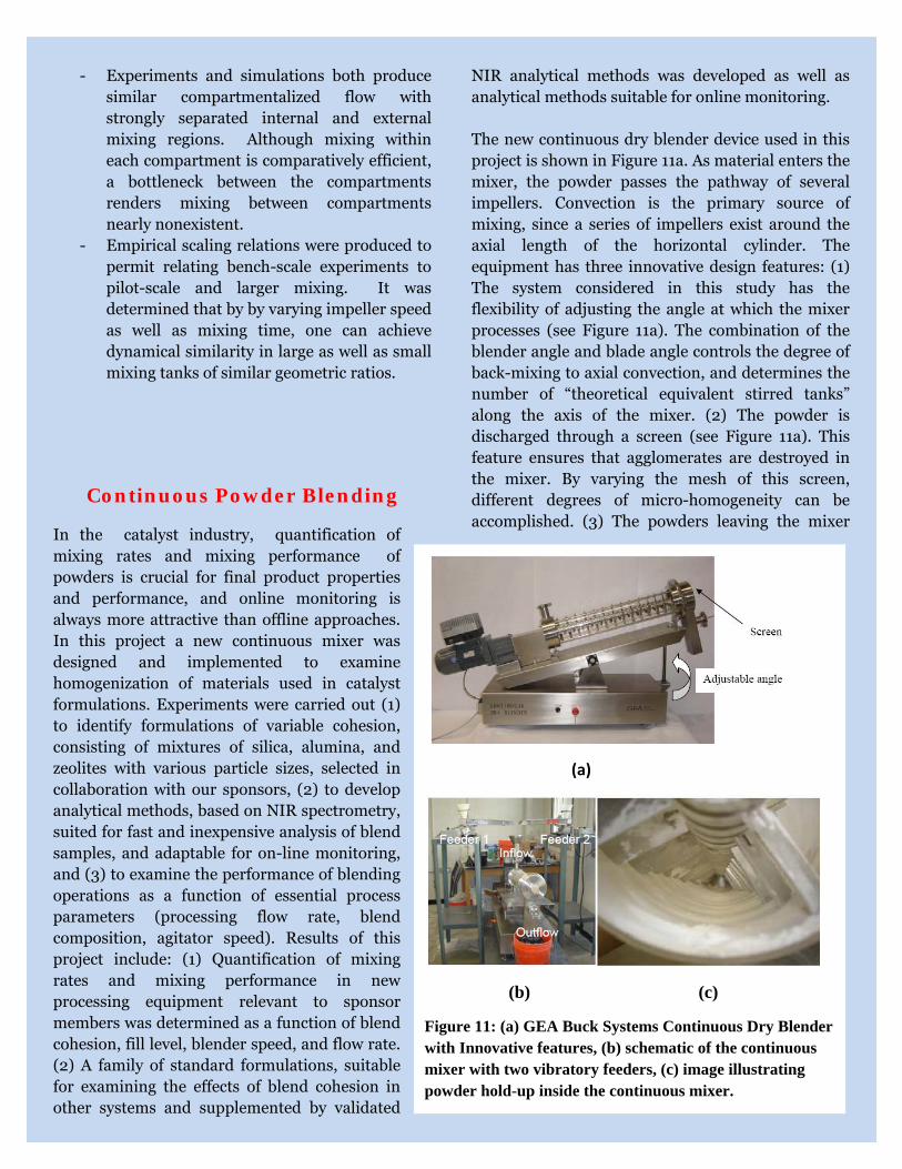
Continuous Powder Blending
In the catalyst industry, quantification of mixing rates and mixing performance of powders is crucial for final product properties and performance, and online monitoring is always more attractive than offline approaches. In this project a new continuous mixer was designed and implemented to examine homogenization of materials used in catalyst formulations. Experiments were carried out (1) to identify formulations of variable cohesion, consisting of mixtures of silica, alumina, and zeolites with various particle sizes, selected in collaboration with our sponsors, (2) to develop analytical methods, based on NIR spectrometry, suited for fast and inexpensive analysis of blend samples, and adaptable for on-line monitoring, and (3) to examine the performance of blending operations as a function of essential process parameters (processing flow rate, blend composition, agitator speed). Results of this project include: (1) Quantification of mixing rates and mixing performance in new processing equipment relevant to sponsor members was determined as a function of blend cohesion, fill level, blender speed, and flow rate. (2) A family of standard formulations, suitable for examining the effects of blend cohesion in other systems and supplemented by validated
NIR analytical methods was developed as well as analytical methods suitable for online monitoring. The new continuous dry blender device used in this project is shown in Figure 11a. As material enters the mixer, the powder passes the pathway of several impellers. Convection is the primary source of mixing, since a series of impellers exist around the axial length of the horizontal cylinder. The equipment has three innovative design features: (1) The system considered in this study has the flexibility of adjusting the angle at which the mixer processes (see Figure 11a). The combination of the blender angle and blade angle controls the degree of back-mixing to axial convection, and determines the number of “theoretical equivalent stirred tanks” along the axis of the mixer. (2) The powder is discharged through a screen (see Figure 11a). This feature ensures that agglomerates are destroyed in the mixer. By varying the mesh of this screen, different degrees of micro-homogeneity can be accomplished. (3) The powders leaving the mixer
(a)
(b) (c)
Figure 11: (a) GEA Buck Systems Continuous Dry Blender with Innovative features, (b) schematic of the continuous mixer with two vibratory feeders, (c) image illustrating powder hold-up inside the continuous mixer.

may also re-enter as a recycle stream. Standard catalytic materials of varying cohesion were tested in this work. The main observations are as follows: (1) Mixing performance is largely limited by the quality of the feeders. As shown in Figure 11(b), two Eriez vibratory feeders were used to feed the powder into the mixer. (2) Mixing quality improves with residence time. (3) The number and spacing of blades plays a critical role in minimizing stagnant regions in the blender. (4) Mixing is better at higher speeds. (5) Incline angle has an effect on performance, but results at this point do not display a simple trend. (6) Electrostatic agglomeration of cohesive powders on the surface of blades was observed. the cohesive powders then accumulated in stagnant regions, strongly affecting the concentration of the discharge stream (see Figure 11c).
Contact Information:
Professor Benjamin Glasser, Director CMSEC, [email protected]
Dr. Arthur Chester, Industrial Liaison CMSEC, [email protected]
Department of Chemical and Biochemical Engineering
Rutgers University
98 Brett Road
Piscataway, NJ 08854‐8058, USA
Phone: (848) 445‐4243; Fax: (732) 445‐2581
Website: http://sol.rutgers.edu/catalyst