catalogue hy11-3500/uk chapter 6: contents...
TRANSCRIPT
6-1
Catalogue HY11-3500/UK
Parker Hannifin GmbH & Co. KGHydraulic Controls DivisionKaarst, Germany
content06.INDD RH
6
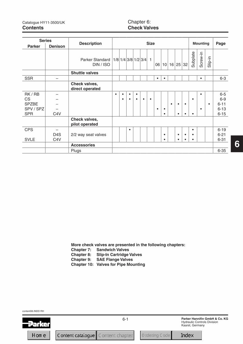
ContentsChapter 6:Check Valves
More check valves are presented in the following chapters:Chapter 7: Sandwich ValvesChapter 8: Slip-In Cartridge ValvesChapter 9: SAE Flange ValvesChapter 10: Valves for Pipe Mounting
SeriesDescription Size Mounting Page
Parker Denison
Parker StandardDIN / ISO
1/8 1/4 3/8 1/2 3/4 106 10 16 25 32 S
ubpl
ate
Scr
ew-in
Slip
-in
Shuttle valvesSSR – • • • 6-3
Check valves,direct operated
RK / RBCSSPZBESPV / SPZSPR
––––
C4V
• ••
••
•• • •
• ••
• •
•
•
•
•
•
•
••
6-56-9
6-116-136-15
Check valves,pilot operated
CPS
SVLE
–D4SC4V
2/2 way seat valves•
••
••
••
•••
6-196-216-31
AccessoriesPlugs 6-35

6-2
content06.INDD RH
Catalogue HY11-3500/UK
Parker Hannifin GmbH & Co. KGHydraulic Controls DivisionKaarst, Germany
6
Notes

6-3
Shuttle ValveSeries SSR
Catalogue HY11-3500/UK
Parker Hannifin GmbH & Co. KGHydraulic Controls DivisionKaarst, Germany
SSR_UK.INDD RH
6
Seal Factorynorm,direct
operated
Ordering code
Designseries
Shuttlevalve
The shuttle valve series SSR is designed as a threadedcartridge valve. All parts are assembled in one unit andeasy to mount.
Valvesize
Threadedcartridge
Features
• Little space required
• Leak-free
• Easy assembly
Design Threaded cartridge valveMounting position UnrestrictedAmbient temperature [°C] -40 ... +60Nominal size NG06 NG10Weight [kg] 0.5 0.8HydraulicFlow direction See symbolsFluid Hydraulic oil as per DIN 51 524 ... 525Viscosity recommended [cSt] [mm²/s] 30 ... 80
permitted [cSt] [mm²/s] 20 ... 380Fluid temperature [°C] -20 ... +60Filtration ISO 4406 (1999); 18/16/13Nominal pressure [bar] 350Flow [l/min] 40 60
Technical data
Characteristics / Ordering Code
Code Sealomit NBR
V FPM
Code Size06 NG0610 NG10
BSSR E080

6-4
SSR_UK.INDD RH
Shuttle ValveSeries SSR
Catalogue HY11-3500/UK
Parker Hannifin GmbH & Co. KGHydraulic Controls DivisionKaarst, Germany
6
Mounting cavity
Dimensions
Dimensions NG06 NG10d1 25 35d2 M18 x 1.5 M24 x 1.5
d3H7 16 22d4H7 14 20d5max. 6 9d6max. 6 9
t1 45 68t2 32 51t3 16 20t4 10 15t5 27.5 40t6 12 13.5
Dimensions NG06 NG10D 24 34L 50 74d M18x1.5 M24x1.5l 45 66
SW 8 12
NG NBR seals FPM seals06 SK-SSRB0E06 SK-SSRB0E06V10 SK-SSRB0E10 SK-SSRB0E10V
Seal kits

6-5
Catalogue HY11-3500/UK
Parker Hannifin GmbH & Co. KGHydraulic Controls DivisionKaarst, Germany
Threaded Check ValvesSeries RK, RB
6
RK-RB_UK.INDD RH
Characteristics / Ordering Code
Technical dataSeries design with pipe thread
The check valves are designed to go into simple, threadedcavities. The connection is O-ring sealed on the 118°shoulder in the mounting cavity.
Code RK0 RK1 RK2 RK3 RB1 RB2 RB3Flow [l/min] 10 20 50 80 20 50 80Operating pressure [bar] 700 700 700 500 700 700 500Opening pressure [bar] 0.15 0.18 0.2 0.25 0.15 0.07 0.17Thread (DIN ISO 228/1) G1/8A G1/4A G3/8A G1/2A G1/4A G3/8A G1/2ATightening torque* ±20% [Nm] 10 15 20 40 15 20 40Weigh [g] 5 5 15 15 5 15 20Mounting position unrestrictedFluid Hydraulic oil in accordance with DIN 51524/51525Viscosity permitted [cSt]/[mm²/s] 4...1500 ; opt. 10...500 viscosity recommendedTemperatures [°C] Ambient and oil -40...+80, observe viscosity range.
* In case of strong vibration, it is recommended to secure the mounting threads.
Type RK
Type RB
Checkvalve,
screwable
Mountingdirection
Size
* only series RK available
Ordering code
Code Mountingdirection
Kin the blocked
direction
Bin open flow
direction
Code Flow [l/min] Thread0* 10 G1/8A1 20 G1/4A2 50 G3/8A3 80 G1/2A
R

6-6
RK-RB_UK.INDD RH
Catalogue HY11-3500/UK
Parker Hannifin GmbH & Co. KGHydraulic Controls DivisionKaarst, Germany
Threaded Check ValvesSeries RK, RB
6
Characteristics
Mounting direction
Type RK
Screwed in,in the blocked direction
Screwed in,in the open flow direction
Type D2 a d3
RK0 8.6 2 1.5RK1 11.5 2.5 2RK2 15 2 2.5RK3 18.8 4 3.5
Mounting toolType RK
∆p/Q perfomance curvesOil viscosity during measurement 50mm²/s
Type RB

6-7
Catalogue HY11-3500/UK
Parker Hannifin GmbH & Co. KGHydraulic Controls DivisionKaarst, Germany
Threaded Check ValvesSeries RK, RB
6
RK-RB_UK.INDD RH
1) Thread runout x must be maintained. It may be smaller, butnot larger (requirement for a perfect seal using the O-ring).
2) Fully cut-out thread
Mounting cavity
• for connecting in combination with tube fitting • for internal line channels
Type Thread L l1 d d1 d2 h d.c. O-ringRK0 G1/8A 7.2 4 8.6 1.8 1.6 1.3 6.8 6x1RK1 G1/4A 9 4.5 11.5 2.4 2.2 1.5 8.8-0.1 9x1RK2 G3/8A 11 6 15 3.2 3 2.5 11 11x1.5RK3 G1/2A 13 7.5 18.5 4 3.8 3 14.2-0.1 14x1.5
Type Thread L l1 d d1 h ww O-ringRB1 G1/4A 9.8 5 11.6 2 1.3 5 9x1RB2 G3/8A 11.5 7.0 15 2.8 2 6 11x1.5RB3 G1/2A 13.15 7.5 18.5 3.2 2.5 8 14x1.5
Type Thread D D1 t t12) x1) a1 d2
RK0 G1/8 8.7 5 12.3 10 2.3 9.5 5RK1 and RB1 G1/4 11.8 8 14 11 3 11 6RK2 and RB2 G3/8 15.25 9 17 14 3 13 8RK3 and RB3 G1/2 19 12 22 18.5 3.5 16 12
Type Thread D D1 t t12) x1)
RK0 G1/8 8.7 5 16 13.7 2.3RK1 and RB1 G1/4 11.8 8 22 19 3RK2 and RB2 G3/8 15.25 9 24.5 21.5 3RK3 and RB3 G1/2 19 12 29 25.5 3.5
Dimensions
Type RK Type RB
* Required depth depending on type of screw plug, connecting plate,etc. used.
6-8
RK-RB_UK.INDD RH
Catalogue HY11-3500/UK
Parker Hannifin GmbH & Co. KGHydraulic Controls DivisionKaarst, Germany
Threaded Check ValvesSeries RK, RB
6
Notes
6-9
Catalogue HY11-3500/UK
Parker Hannifin GmbH & Co. KGHydraulic Controls DivisionKaarst, Germany
Check ValveSeries CS
6
CS_UK.INDD RH
Code Size400 400 (1/4)600 600 (3/8)800 800 (1/2)1200 1200 (3/4)1600 1600 (1)
SCS
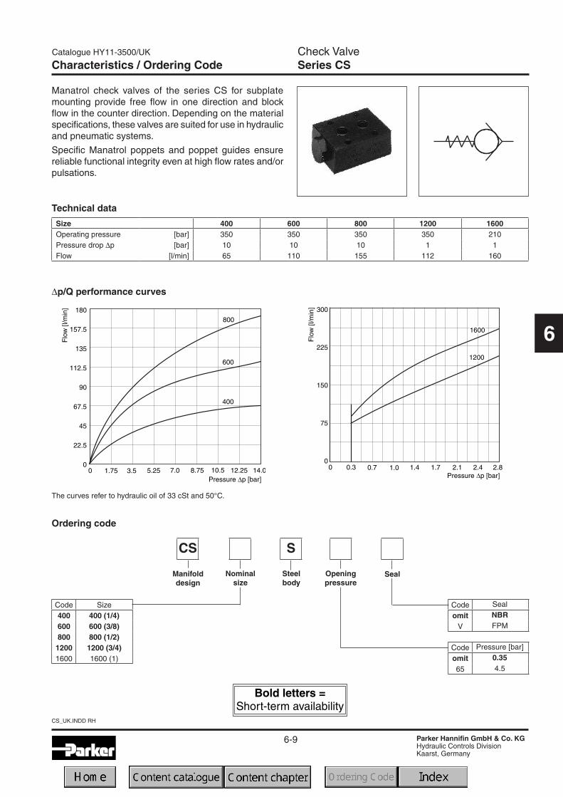
Size 400 600 800 1200 1600Operating pressure [bar] 350 350 350 350 210Pressure drop ∆p [bar] 10 10 10 1 1Flow [l/min] 65 110 155 112 160
Characteristics / Ordering Code
Manatrol check valves of the series CS for subplatemounting provide free flow in one direction and blockflow in the counter direction. Depending on the materialspecifications, these valves are suited for use in hydraulicand pneumatic systems.
Specific Manatrol poppets and poppet guides ensurereliable functional integrity even at high flow rates and/orpulsations.
Technical data
∆p/Q performance curves
The curves refer to hydraulic oil of 33 cSt and 50°C.
SealOpeningpressure
Manifolddesign
Nominalsize
Steelbody
Code Seal
omit NBR
V FPM
Code Pressure [bar]
omit 0.35
65 4.5
Ordering code
6-10
CS_UK.INDD RH
Catalogue HY11-3500/UK
Parker Hannifin GmbH & Co. KGHydraulic Controls DivisionKaarst, Germany
Check ValveSeries CS
6
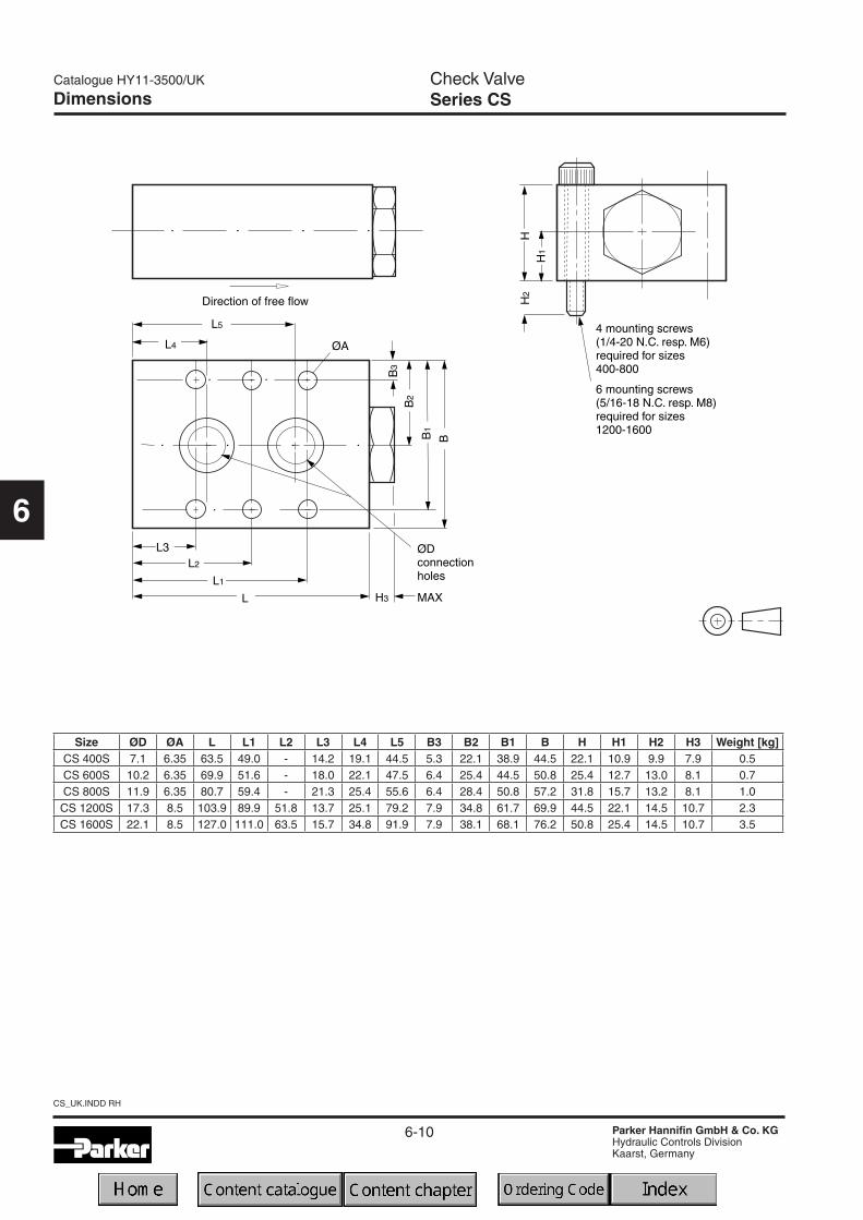
Dimensions
Size ØD ØA L L1 L2 L3 L4 L5 B3 B2 B1 B H H1 H2 H3 Weight [kg]CS 400S 7.1 6.35 63.5 49.0 - 14.2 19.1 44.5 5.3 22.1 38.9 44.5 22.1 10.9 9.9 7.9 0.5CS 600S 10.2 6.35 69.9 51.6 - 18.0 22.1 47.5 6.4 25.4 44.5 50.8 25.4 12.7 13.0 8.1 0.7CS 800S 11.9 6.35 80.7 59.4 - 21.3 25.4 55.6 6.4 28.4 50.8 57.2 31.8 15.7 13.2 8.1 1.0CS 1200S 17.3 8.5 103.9 89.9 51.8 13.7 25.1 79.2 7.9 34.8 61.7 69.9 44.5 22.1 14.5 10.7 2.3CS 1600S 22.1 8.5 127.0 111.0 63.5 15.7 34.8 91.9 7.9 38.1 68.1 76.2 50.8 25.4 14.5 10.7 3.5

6-11
Catalogue HY11-3500/UK
Parker Hannifin GmbH & Co. KGHydraulic Controls DivisionKaarst, Germany
Check ValveSeries SPZBE
6
SPZBE_UK.INDD RH
Code Seal
omit NBR
V FPM
Characteristics / Ordering Code
Design Threaded cartridge valveMounting position OptionalAmbient temperature [°C] -40 ... +60Nominal size NG16 NG25 NG32Weight [kg] 0.25 0.5 1.2HydraulicFlow direction Port A to BFluid Hydraulic oil as per DIN 51 524 ... 536Viscosity recommended [cSt] [mm²/s] 30 ... 80
permitted [cSt] [mm²/s] 20 ... 380Fluid temperature [°C] -20 ... +60Filtration ISO 4406 (1999); 18/16/13Nominal pressure [bar] 350Opening pressure [bar] 0.1; 0.5; 1.6 and 4.0Flow [l/min] 250 450 900
Technical data
Seal Factorynorm,
poppet,direct
operated
Designseries,
screwedcover
Checkvalve
Valvesize
Slip-invalve
Flowdirection
A to B
Openingpressure
Code Pressure [bar]L 0.1N 0.5S 1.6U 4.0
BZSP E1010
Ordering code
The check valves series SPZBE are slip-in cartridgevalves. The function unit is fixed inside the manifold by aplug with hex slot.The design is based on CE series with same poppetand sleeve. The different mounting cavity has to beconsidered.
Features
• Little space required
• Leak-free from port B to A
• 4 different opening pressures
Code Size16 NG1625 NG2532 NG32

6-12
SPZBE_UK.INDD RH
Catalogue HY11-3500/UK
Parker Hannifin GmbH & Co. KGHydraulic Controls DivisionKaarst, Germany
Check ValveSeries SPZBE
6
Dimensions NG16 NG25 NG32D 40 55 72L 72.5 89 109.5d M33x2 G½" G2"l 66 80.5 99.5
SW 17 24 32
NG NBR seals FPM seals16 SK-SPZBE10E16 SK-SPZBE10E16V25 SK-SPZBE10E25 SK-SPZBE10E25V32 SK-SPZBE10E32 SK-SPZBE10E32V
Dimensions
Performance Curves / Dimensions
Mounting cavity
Performance curves
Seal kits Springs
Spring TypeOrdering Number
NG16 NG25 NG32
L 0.1 bar 45051368 45051375 45051376
N 0.5 bar 45051369 45051374 45051377
S 1.6 bar 45051370 45051372 45051378
U 4.0 bar 45051371 45051373 45051379
Size NG16 NG25 NG32d1 18 25.5 36
d2H7 25 34 45d3 31 45 57d5 M33x2 G1½" G2"
d6min 41 56 73t2+0.1 66 80.5 99.5
t3 53 66.5 84.5t4 2 2.5 2.5t5 21 25 30
t6min 16 16 24t6max 52.5 66 84t7 6.5 6.5 10

6-13
Catalogue HY11-3500/UK
Parker Hannifin GmbH & Co. KGHydraulic Controls DivisionKaarst, Germany
Check ValvesSeries SPV, SPZ
6
SPV-SPZ_UK.INDD RH
Code Seal
omit NBR
V FPM
The check valve series SPV and SPZ are designed as athreaded cartridge valve. All parts are assembled in oneunit and easy to mount.
Characteristics / Ordering Code
Features
• Little space required
• Leak-free
• Easy assembly
Design Threaded cartridge valveMounting position UnrestrictedAmbient temperature [°C] -40 ... +60Nominal size NG06 NG10Weight [kg] 0.5 0.8HydraulicFlow direction See symbolsFluid Hydraulic oil as per DIN 51 524 ... 536Viscosity recommended [cSt] [mm²/s] 30 ... 80
permitted [cSt] [mm²/s] 20 ... 380Fluid temperature [°C] -20 ... +60Filtration ISO 4406 (1999); 18/16/13Nominal pressure [bar] 350Opening pressure [bar] 0.3Flow [l/min] 40 60
Technical data
Ports
Flow direction V Flow direction Z
Seal Factorynorm,direct
operated
Designseries
Checkvalve
Valvesize
Threadedcartridge
Flowdirection
Spring0.3 bar
Code Size06 NG0610 NG10
Code Flow directionV Port B -> A and CZ Port A -> B and C
BSP E030 M
Ordering code
6-14
SPV-SPZ_UK.INDD RH
Catalogue HY11-3500/UK
Parker Hannifin GmbH & Co. KGHydraulic Controls DivisionKaarst, Germany
Check ValvesSeries SPV, SPZ
6
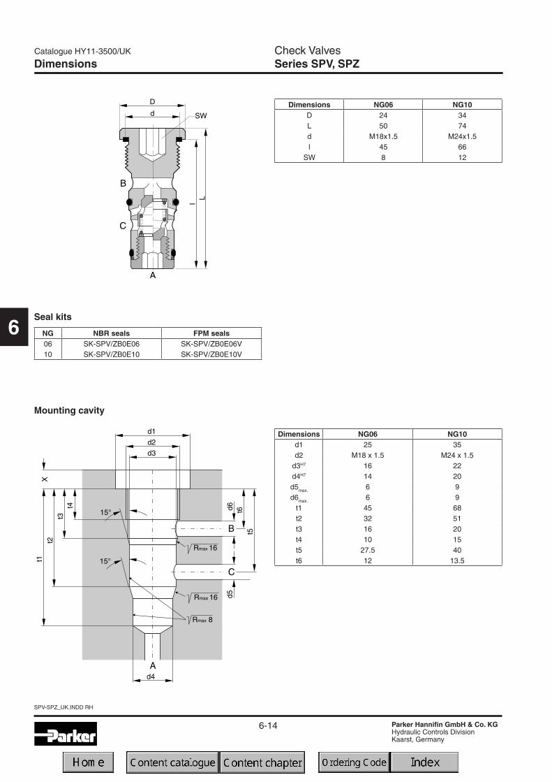
Dimensions
Mounting cavity
Seal kits
Dimensions NG06 NG10d1 25 35d2 M18 x 1.5 M24 x 1.5
d3H7 16 22d4H7 14 20d5max. 6 9d6max. 6 9
t1 45 68t2 32 51t3 16 20t4 10 15t5 27.5 40t6 12 13.5
Dimensions NG06 NG10D 24 34L 50 74d M18x1.5 M24x1.5l 45 66
SW 8 12
NG NBR seals FPM seals06 SK-SPV/ZB0E06 SK-SPV/ZB0E06V10 SK-SPV/ZB0E10 SK-SPV/ZB0E10V
6-15
Check ValvesSeries SPR (Parker), C4V (Denison)
Catalogue HY11-3500/UK
Parker Hannifin GmbH & Co. KGHydraulic Controls DivisionKaarst, Germany
6
SPR-C4V_UK.INDD RH
Characteristics
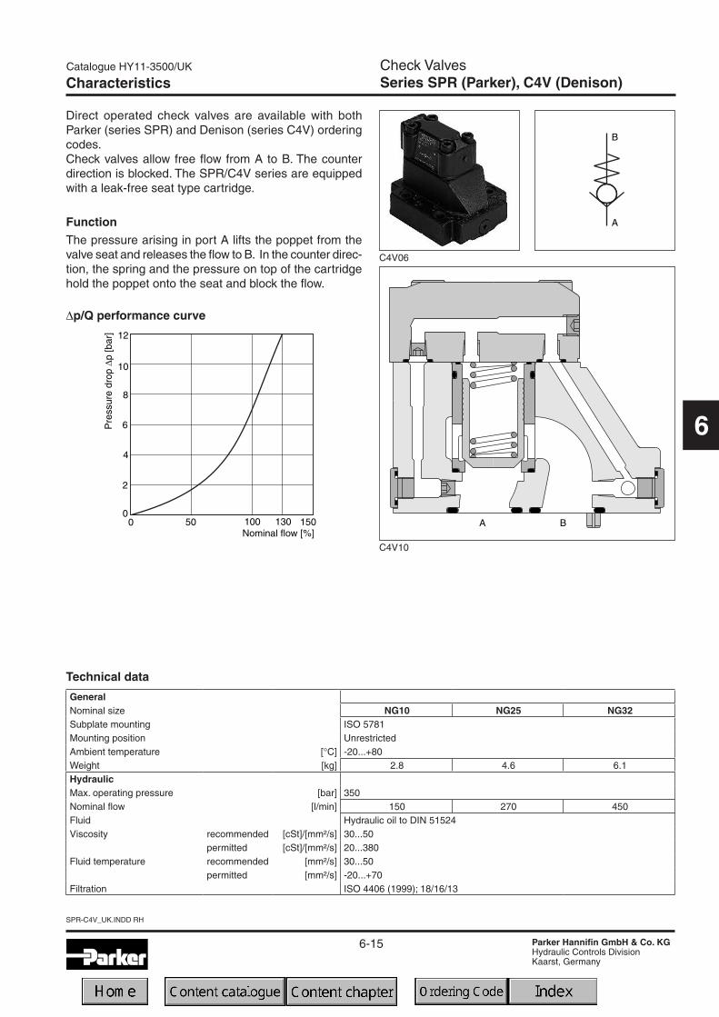
Direct operated check valves are available with bothParker (series SPR) and Denison (series C4V) orderingcodes.Check valves allow free flow from A to B. The counterdirection is blocked. The SPR/C4V series are equippedwith a leak-free seat type cartridge.
FunctionThe pressure arising in port A lifts the poppet from thevalve seat and releases the flow to B. In the counter direc-tion, the spring and the pressure on top of the cartridgehold the poppet onto the seat and block the flow.
C4V06
∆p/Q performance curve
GeneralNominal size NG10 NG25 NG32Subplate mounting ISO 5781Mounting position UnrestrictedAmbient temperature [°C] -20...+80Weight [kg] 2.8 4.6 6.1HydraulicMax. operating pressure [bar] 350Nominal flow [l/min] 150 270 450Fluid Hydraulic oil to DIN 51524Viscosity recommended [cSt]/[mm²/s] 30...50
permitted [cSt]/[mm²/s] 20...380Fluid temperature recommended [mm²/s] 30...50
permitted [mm²/s] -20...+70Filtration ISO 4406 (1999); 18/16/13
Technical data
C4V10
6-16
SPR-C4V_UK.INDD RH
Check ValvesSeries SPR (Parker), C4V (Denison)
Catalogue HY11-3500/UK
Parker Hannifin GmbH & Co. KGHydraulic Controls DivisionKaarst, Germany
6
Seal SeriesCheckvalve
Valvesize
Code Sealomit NBR
V FPM
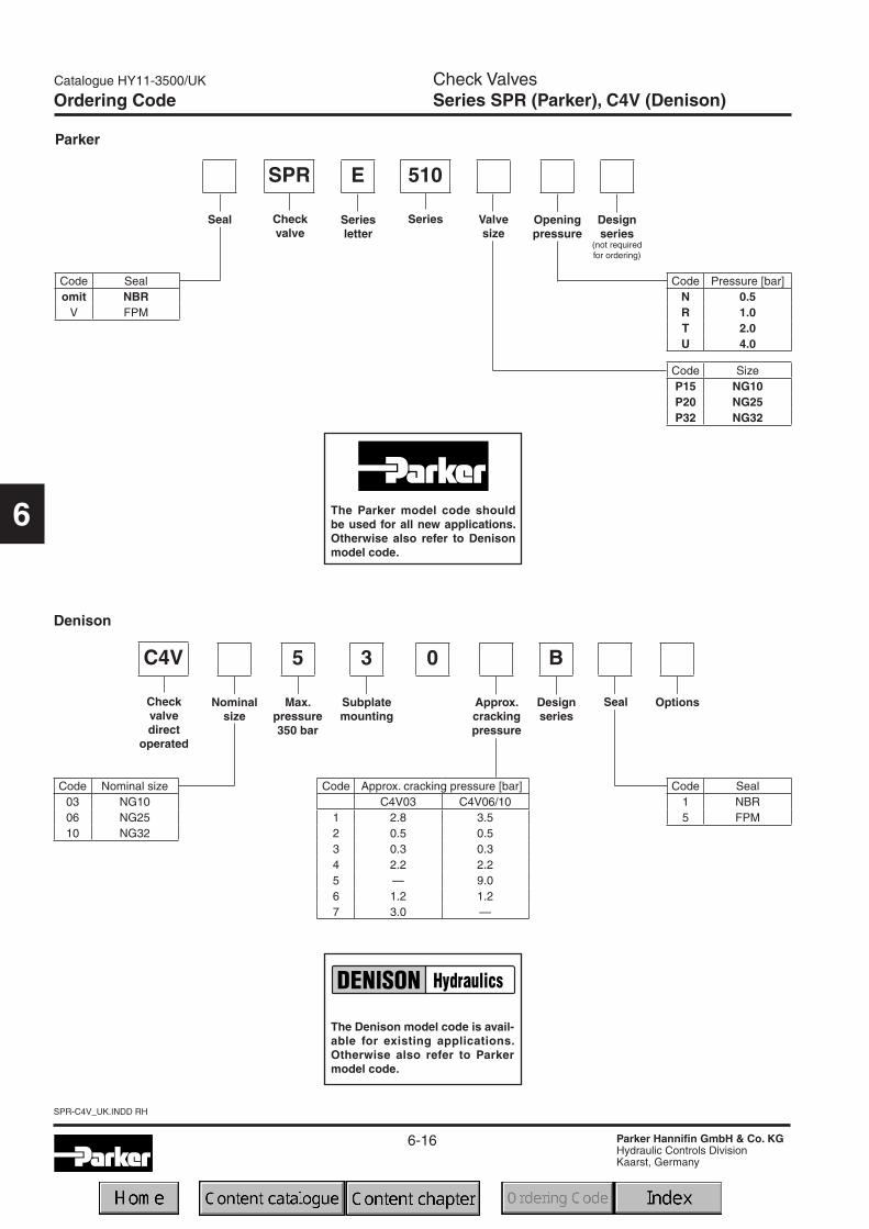
ESPR 510
Parker
Code Pressure [bar]N 0.5R 1.0T 2.0U 4.0
Seriesletter
Openingpressure
Code SizeP15 NG10P20 NG25P32 NG32
Designseries
Denison
Ordering Code
SealCheckvalvedirect
operated
Code Seal1 NBR5 FPM
C4V 0
Code Approx. cracking pressure [bar]C4V03 C4V06/10
1 2.8 3.52 0.5 0.53 0.3 0.34 2.2 2.25 — 9.06 1.2 1.27 3.0 —
OptionsApprox.crackingpressure
Code Nominal size03 NG1006 NG2510 NG32
B
Designseries
Nominalsize
5
Max.pressure350 bar
3
Subplatemounting
The Denison model code is avail-able for existing applications.Otherwise also refer to Parkermodel code.
The Parker model code shouldbe used for all new applications.Otherwise also refer to Denisonmodel code.
(not requiredfor ordering)

6-17
Check ValvesSeries SPR (Parker), C4V (Denison)
Catalogue HY11-3500/UK
Parker Hannifin GmbH & Co. KGHydraulic Controls DivisionKaarst, Germany
6
SPR-C4V_UK.INDD RH
Dimensions
Tolerance for all dimensions ±0.2
NG ISO-code x1 x2 x3 x4 x5 y1 y2 B1 B2 H1 H2 H3 L1 L210 5781-06-07-0-00 42.9 35.8 - 7.2 31.8 66.7 33.4 87.3 33.4 83 21 45 29 94.825 5781-08-10-0-00 60.3 49.2 - 11.1 44.5 79.4 39.7 105 39.7 109.5 29 71.5 34.7 126.832 5781-10-13-0-00 84.2 67.5 42.1 16.7 62.7 96.8 48.4 120 48.4 120 29 82 30.6 144.3
NG ISO-code d1max d2 t1 d3 t2 d4 d510 5781-06-07-0-00 15 7.1 8 M10 16 10.8 1725 5781-08-10-0-00 23.4 7.1 8 M10 18 10.8 1732 5781-10-13-0-00 32 7.1 8 M10 20 10.8 17
NG ISO-code NBR FPM Surface finish
10 5781-06-07-0-00 BK-M10 x 35-4pcs 68 Nm SK-SVLE5P10 SK-SVLE5P10V25 5781-08-10-0-00 BK-M10 x 45-4pcs 68 Nm SK-SVLE5P25 SK-SVLE5P25V32 5781-10-13-0-00 BK-M10 x 45-6pcs 68 Nm SK-SVLE5P32 SK-SVLE5P32V
6-18
SPR-C4V_UK.INDD RH
Catalogue HY11-3500/UK
Parker Hannifin GmbH & Co. KGHydraulic Controls DivisionKaarst, Germany
6
Notes

6-19
Catalogue HY11-3500/UK
Parker Hannifin GmbH & Co. KGHydraulic Controls DivisionKaarst, Germany
Pilot Operated Check ValveSeries CPS
6
CPS_UK.INDD RH
Code Sealomit NBR
V FPM
Code Port size600 NG061200 NG10
S M
Size 600 1200Max. operating pressure [bar] 210 210Max. pilot pressure [bar] 210 70Flow Qmax at ∆p 2,7bar [l/min] 30 95Nominal size 3/8 3/4Weight [kg] 4 7
Characteristics / Ordering Code
Surface ratio 5 : 1(pilot spool: poppetsurface) for quick re-sponse time withoutdecompression.
Surface ratio 40 : 1(pilot spool: decom-pression pin surface)for low shock or oscil-lation performancefrom decompression.
Technical data
Ordering code
CP S
Portsize
Steelpoppet
Pilotratio
Manifoldmounting
Pilotoperated
checkvalve
Steelbody
Seal
Code Ratio Stage5 5:1 140 40:1 2
Pilot operated check valves of the series CP allow freeflow in one direction (A to B).
The counter-flow direction (B to A) is blocked. By apply-ing pilot pressure, the poppet can be lifted from its seatagainst the pressure in port B. Thus flow in the counter-direction is also possible. There are 1 and 2 stage pop-pets available with pilot ratios of 1 : 5 and 1 : 40, to suitdifferent operating conditions.
Pilot ratiosPoppet 1 stage Poppet 2 stage

6-20
CPS_UK.INDD RH
Catalogue HY11-3500/UK
Parker Hannifin GmbH & Co. KGHydraulic Controls DivisionKaarst, Germany
Pilot Operated Check ValveSeries CPS
6
Performance Curves / Dimensions
Size L3 L2 L1 L9 L11 H H1 H2 H3 L10 L8 L7 L6 B3 B2 B1 B ØH L5 L4CPS600S 76.2 101.6 120.7 10.7 1.0 50.8 25.4 12.7 7.9 - 108.0 60.2 12.7 8.6 38.1 67.3 76.2 11.2 21.3 53.3CPS1200S 93.7 127.0 152.4 11.4 1.0 63.5 31.8 12.7 10.2 7.9 136.4 76.2 15.7 10.2 50.8 91.2 101.6 19.1 25.4 63.5
6 mounting screwsM6 for size 6006 mounting screwsM8 for size 1200
∆p/Q performance curves
The curves refer to hydraulic oil of 33 cSt and 50°C.
Dimensions

6-21
Catalogue HY11-3500/UK
Parker Hannifin GmbH & Co. KGHydraulic Controls DivisionKaarst, Germany
Directional Seat ValveSeries D4S (Denison)
6
D4S_UK.INDD RH
Characteristics
Seat valves series D4S are designed for directional controlfunctions. A large variety of poppets, springs and covers- including shuttle valves, stroke limiters, solenoid valves(VV01) and position control - allow to design individualhydraulic solutions for nominal flow up to 600 l/min.
A complete program is offered under the Denison brand:subplate mounted valves (D4S - chapter 6),SAE flange valves (D5S - chapter 9),pipe mounted valves (D4S - chapter 10),slip-in cartridges (CAR - on request).
Features• Leak-free seat valve design
• Numerous pilot options
• 6 poppet types
• 3 sizes, NG10, 25, 32
D4S10

6-22
D4S_UK.INDD RH
Catalogue HY11-3500/UK
Parker Hannifin GmbH & Co. KGHydraulic Controls DivisionKaarst, Germany
Directional Seat ValveSeries D4S (Denison)
6
Code Optionsomit Standard
013Cover for end
position control
Code Nominal size03 NG1006 NG2510 NG32
9D4S
Seatvalve
Spooltype
Nominalsize
2) Springs 2, 3, 4 and 6 only
Subplatemounting
ISO 6264 Y1port G¼"
Code Sleeve1 AA=95%, AB=5%3 AA=60%, AB=40%
B
Designseries
Seals
Code Pilot oil line in bodyA-X B-Y
1 internal from A2 internal from X
A1) internal from AB1) external from XC internal from A + BD internal from BG external from Y
Sleeve Switchingtype
Solenoidvoltage
Code Solenoid voltageomit StandardG0R 12V=G0Q 24V=GAR 98V=GAG 205V=W06 115V / 50HzW07 230V / 50Hz
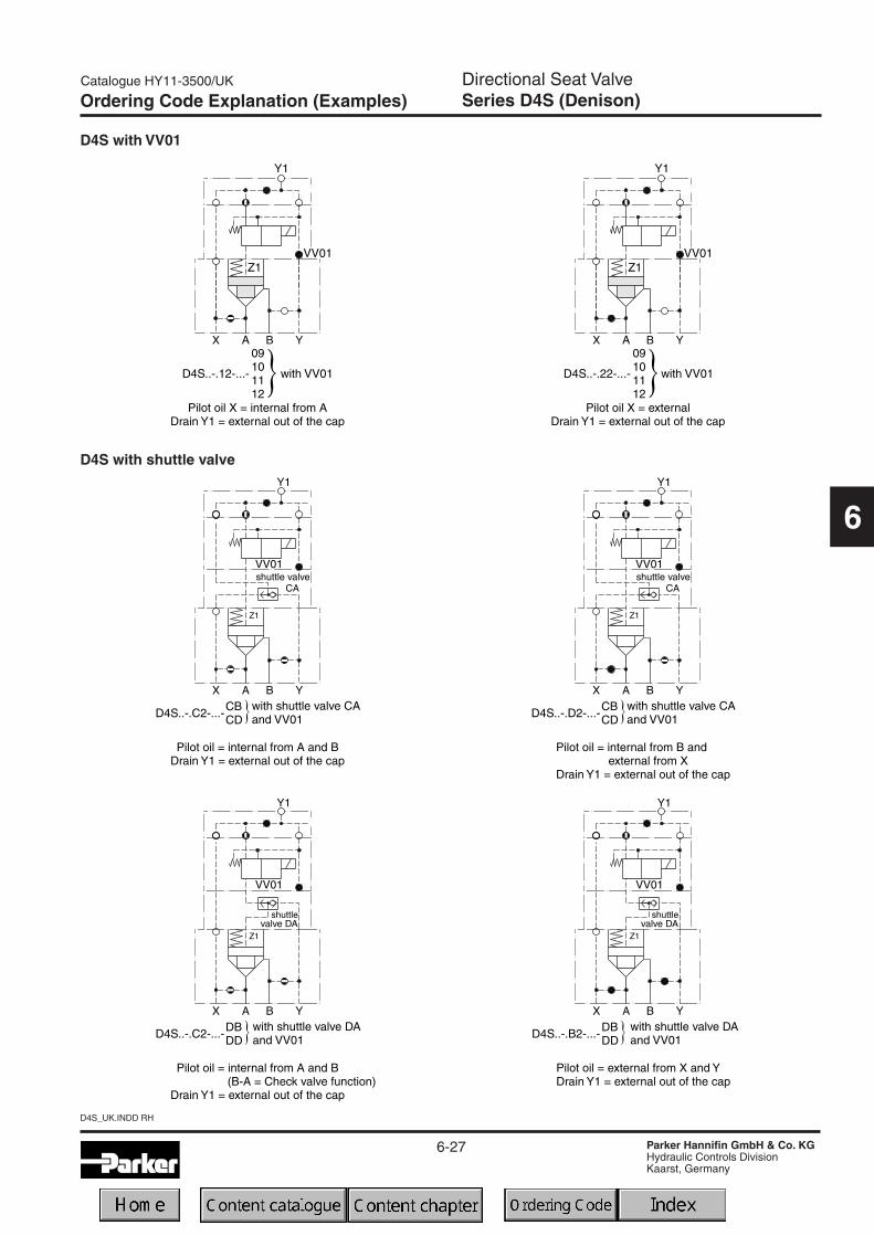
Code Switching typeomit Standard09 VV01 with manual override de-energized: power
comp. open10 VV01 without manual override11 VV01 with manual override de-energized: power
comp. closed12 VV01 without manual override
CA Shuttle valve
DA Shuttle valve
CB VV01 code 09 and shuttle valve code CACD VV01 code 11 and shuttle valve code CADB VV01 code 09 and shuttle valve code DADD VV01 code 11 and shuttle valve code DA
BHVV01 code 10 and shuttle valve code CA and position
control 3) with amplifier
BKVV01 code 12 and shuttle valve code CA and position
control 3) with amplifier
BNVV01 code 10 and shuttle valve code DA and position
control 3) with amplifier
BQVV01 code 12 and shuttle valve code DA and position
control 3) with amplifierBC VV01 code 10 and position control 3) with amplifierBE VV01 code 12 and position control 3) with amplifierBA Position control 3) with amplifierBF Position control 3) with amplifier and shuttle valve code CABL Position control 3) with amplifier and shuttle valve code DA
Capversion
Pilotconnec-
tion
Code Size Poppet type Sleeve
1 03, 06,10With closed bottom and 15° chamfer (pZ max.
= pA +20bar1
203
With 0.8 dia. orifice at the bottom and 15°chamfer
1
06, 10With 1.2 dia. orifice at the bottom and 15°
chamfer1
4 03, 06,10 With closed bottom and 45° chamfer 1, 3A 2) 06, 10 Safety spool (for position control only) 3B 2) 06, 10 Throttle spool, 10° chamfer 3C 2) 06, 10 Throttle spool, 3° chamfer 3
Code Seals1 NBR5 FPM
3) Position control for D4S06/10 only.Spring 2 or 4. Spool A and sleeve 3.Valve open: proximity switch damped.
OptionsSpring
Code
Spring (approx. cracking pressure [bar])Sleeve Code 1 Sleeve Code 3
A -> B A -> B B -> AD5S03 D5S06/10 D5S03 D5S06/10 D5S03 D5S06/10
1 2.8 3.5 6.5 6.5 9.5 11.02 0.5 0.5 1.0 1.0 1.5 1.73 0.3 0.3 0.6 0.6 0.9 1.04 2.2 2.2 4.0 3.5 5.5 6.05 — 9.0 — 16.0 — 28.06 1.2 1.2 2.0 2.2 3.0 3.87 3.0 — 8.0 — 12.0 —
1) With VV01 only
Ordering Code Technical Data
Code Ports X Y Z X-Y Y1 VV01Standard
1 Pilot oil = pilot drain — —C Pilot oil = pilot drain —
With solenoid valve (VV01)2 Ext. PD from cap —6 Internal pilot drain — —
With stroke limiter (not for D4S03)3 Pilot oil = pilot drain — — — —4 Pilot oil = pilot drain — — — —
open bore closed bore orifice Ø 1.2

6-23
Catalogue HY11-3500/UK
Parker Hannifin GmbH & Co. KGHydraulic Controls DivisionKaarst, Germany
Directional Seat ValveSeries D4S (Denison)
6
D4S_UK.INDD RH
Electrical (solenoid)Duty ratio [%] 100
Response time [ms] Energized / de-energized AC: 20/18 , DC: 46/27
Code G0R G0Q GAR GAG W06 W07
12V = 24V = 98V = 205V = 150 at 50Hz 230 at 50Hz
+5...-10 +5...-10 +5...-10 +5...-10 +5...-10 +5...-10
31 31 31 31 78 78
31 31 31 31 264 264
Supply voltage [V]
Tolerance supply voltage [%]
Power consumption, hold [W]
Power consumption, in rush [W]
Max. switching frequency [1/h] AC: up to 7.200, DC: up to 16.000
Solenoid connection Connector as per EN175301-803
Protection class IP65 in accordance with EN 60529 (plugged and mounted)
Coil insulation class H (180 °C)
GeneralSize 03 06 10Mounting Subplate mounting acc. to ISO 6264
Mounting position unrestricted
Ambient temperature [°C] -20...+50
Weight [kg] 2.7 4.5 6.0
HydraulicOperating pressure [bar] Ports A, B up to 350; Port Y 140 (with VV01)
Nominal flow [l/min] 180 360 600
Fluid Hydraulic oil as per DIN 51524...525
Fluid temperature [°C] -20...+80
Viscosity permitted [cSt]/[mm2/s] 10...650
Viscosity recommended [cSt]/[mm2/s] 30
Filtration ISO 4406 (1999) 18/16/13 (acc. NAS 1638: 7)
Technical Data
D4S pilot configuration
Subplate mounting

6-24
D4S_UK.INDD RH
Catalogue HY11-3500/UK
Parker Hannifin GmbH & Co. KGHydraulic Controls DivisionKaarst, Germany
Directional Seat ValveSeries D4S (Denison)
6
Characteristics
p/Q performance curves
Sleeve 1, poppet 1 Sleeve 1, poppet 2 Sleeve 1, poppet 4 Sleeve 3, poppet 4 Sleeve 3, poppet A Sleeve 3, poppet B/C
1 : 1.05 1 : 1.05 1 : 1.05 1 : 1.67 1 : 1.67 1 : 1.67AA = 0.95 AC AA = 0.95 AC AA = 0.95 AC AA = 0.6 AC AA = 0.6 AC AA = 0.6 AC
AB = 0.05 AC AB = 0.05 AC AB = 0.05 AC AB = 0.4 AC AB = 0.4 AC AB = 0.4 AC
15° chamfer 15° chamfer 45° chamfer 45° chamfer 45° chamfer 45° chamferorifice safety spool throttle spool
Selection of Cartridges
6-25
Catalogue HY11-3500/UK
Parker Hannifin GmbH & Co. KGHydraulic Controls DivisionKaarst, Germany
Directional Seat ValveSeries D4S (Denison)
6
D4S_UK.INDD RH
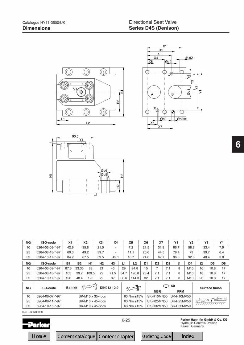
Dimensions
NG ISO-code X1 X2 X3 X4 X5 X6 X7 Y1 Y2 Y3 Y410 6264-06-09-*-97 42.9 35.8 21.5 - 7.2 21.5 31.8 66.7 58.8 33.4 7.9
25 6264-08-13-*-97 60.3 49.2 39.7 - 11.1 20.6 44.5 79.4 73 39.7 6.4
32 6264-10-17-*-97 84.2 67.5 59.5 42.1 16.7 24.6 62.7 96.8 92.8 48.4 3.8
NG ISO-code B1 B2 H1 H2 H3 L1 L2 D1 D2 D3 t1 D4 t2 D5 D610 6264-06-09-*-97 87.3 33.35 83 21 45 29 94.8 15 7 7.1 8 M10 16 10.8 17
25 6264-08-13-*-97 105 39.7 109.5 29 71.5 34.7 126.8 23.4 7.1 7.1 8 M10 18 10.8 17
32 6264-10-17-*-97 120 48.4 120 29 82 30.6 144.3 32 7.1 7.1 8 M10 20 10.8 17
NG ISO-code Bolt kit - DIN912 12.9 Surface finishNBR FPM
10 6264-06-07-*-97 BK-M10 x 35-4pcs 63 Nm ±15% SK-R10MN50 SK-R10MV50
25 6264-08-11-*-97 BK-M10 x 45-4pcs 63 Nm ±15% SK-R25MN50 SK-R25MV50
32 6264-10-15-*-97 BK-M10 x 45-6pcs 63 Nm ±15% SK-R32MN50 SK-R32MV50

6-26
D4S_UK.INDD RH
Catalogue HY11-3500/UK
Parker Hannifin GmbH & Co. KGHydraulic Controls DivisionKaarst, Germany
Directional Seat ValveSeries D4S (Denison)
6
Ordering Code Explanation (Examples)
D4S direct operated D4S with
D4S with VV01
6-27
Catalogue HY11-3500/UK
Parker Hannifin GmbH & Co. KGHydraulic Controls DivisionKaarst, Germany
Directional Seat ValveSeries D4S (Denison)
6
D4S_UK.INDD RH
Ordering Code Explanation (Examples)
D4S with VV01
D4S with shuttle valve

6-28
D4S_UK.INDD RH
Catalogue HY11-3500/UK
Parker Hannifin GmbH & Co. KGHydraulic Controls DivisionKaarst, Germany
Directional Seat ValveSeries D4S (Denison)
6
Ordering Code Explanation (Examples)
D4S with position control Dimensions D4S with
D4S with stroke limiter

6-29
Catalogue HY11-3500/UK
Parker Hannifin GmbH & Co. KGHydraulic Controls DivisionKaarst, Germany
Directional Seat ValveSeries D4S (Denison)
6
D4S_UK.INDD RH
Dimensions D4S with VV01
Dimensions
() Dimensions in brackets are for version VV01with shuttle valve codeDB or DD.
Note: Shuttle valves only use in connection with vent valve VV01.
Dimensions D4S with shuttle valve

6-30
D4S_UK.INDD RH
Catalogue HY11-3500/UK
Parker Hannifin GmbH & Co. KGHydraulic Controls DivisionKaarst, Germany
Directional Seat ValveSeries D4S (Denison)
6
Dimensions D4S stroke limiter
Dimensions
Dimensions D4S position control
Function PNP, contactSupply voltage (Us) [VDC] 10...30Supply voltage ripple [%] 10Current consumption [mA] max. 8Residual voltage L-signal [V] Us - 2.2 at lmax
Output current (I) [mA] 200Protection class IP67Ambient temperature [C°] -25...+70Wire cross section [mm2] 3 x 0.5
Technical data (proximity switch)
Position control by proximity switch (incl. amplifier)Valve open: proximity switch activated.
This proximity switch is pressure proof and has no wea-ring parts.
NotePosition control for D4S06 and D4S10 only.
Note:Stroke limiter not for use with D4S03, vent valve VV01, shuttle valve and positon control.
6-31
Hydraulically Pilot Operated Check ValvesSeries SVLE (Parker), C4V (Denison)
Catalogue HY11-3500/UK
Parker Hannifin GmbH & Co. KGHydraulic Controls DivisionKaarst, Germany
6
SVLE-C4V_UK.INDD RH
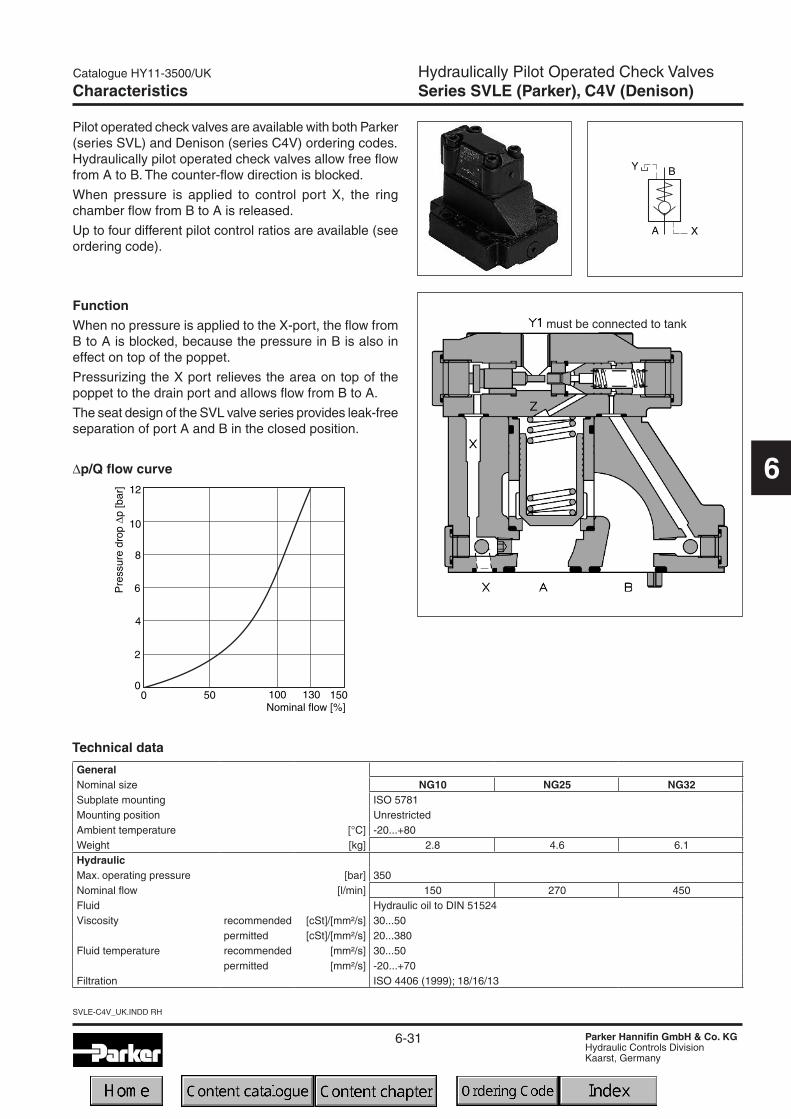
Characteristics
Pilot operated check valves are available with both Parker(series SVL) and Denison (series C4V) ordering codes.Hydraulically pilot operated check valves allow free flowfrom A to B. The counter-flow direction is blocked.
When pressure is applied to control port X, the ringchamber flow from B to A is released.
Up to four different pilot control ratios are available (seeordering code).
FunctionWhen no pressure is applied to the X-port, the flow fromB to A is blocked, because the pressure in B is also ineffect on top of the poppet.
Pressurizing the X port relieves the area on top of thepoppet to the drain port and allows flow from B to A.
The seat design of the SVL valve series provides leak-freeseparation of port A and B in the closed position.
Technical data
GeneralNominal size NG10 NG25 NG32Subplate mounting ISO 5781Mounting position UnrestrictedAmbient temperature [°C] -20...+80Weight [kg] 2.8 4.6 6.1HydraulicMax. operating pressure [bar] 350Nominal flow [l/min] 150 270 450Fluid Hydraulic oil to DIN 51524Viscosity recommended [cSt]/[mm²/s] 30...50
permitted [cSt]/[mm²/s] 20...380Fluid temperature recommended [mm²/s] 30...50
permitted [mm²/s] -20...+70Filtration ISO 4406 (1999); 18/16/13
∆p/Q flow curve
must be connected to tank

6-32
SVLE-C4V_UK.INDD RH
Hydraulically Pilot Operated Check ValvesSeries SVLE (Parker), C4V (Denison)
Catalogue HY11-3500/UK
Parker Hannifin GmbH & Co. KGHydraulic Controls DivisionKaarst, Germany
6
ESVL 5LR
Seal Hydr. pilotoperated
Checkvalve
Nominalsize
Poppettype 04
Closingspring
Designstyle to
ISO 5781
DesignSeries
(not requiredfor ordering)
Pilotcontrol
ratio
Subplatemounting
Externaldrain portY1 (G1/4")
Ordering Code
4
Code Sealomit NBR
V FPM
Code Ratio1 1 : 13 3 : 18 8 : 19 10 : 1
Code Pressure [bar]N 0.5R 1.0T 2.0U 4.0
Code SizeP15 NG10P20 NG25P32 NG32
Parker
Denison
SealCheckvalvepilot
operated
Code Seal1 NBR5 FPM
C4V
Code Approx. cracking pressure [bar]Flow A to B Flow B to A
C4V03 C4V06/10 C4V03 C4V06/102 1.0 1.0 1.5 1.74 4.0 3.5 5.5 6.06 2.0 2.2 3.0 3.8
OptionsApprox.crackingpressure
Code Nominal size03 NG1006 NG2510 NG32
B
Designseries
Nominalsize
5
Max.pressure350 bar
9
Y1-portG¼"
Openingratio
Code Opening ratio1 1 : 13 3 : 18 8 : 19 9 : 1
The Denison model code is avail-able for existing applications.Otherwise also refer to Parkermodel code.
The Parker model code shouldbe used for all new applications.Otherwise also refer to Denisonmodel code.
6-33
Hydraulically Pilot Operated Check ValvesSeries SVLE (Parker), C4V (Denison)
Catalogue HY11-3500/UK
Parker Hannifin GmbH & Co. KGHydraulic Controls DivisionKaarst, Germany
6
SVLE-C4V_UK.INDD RH
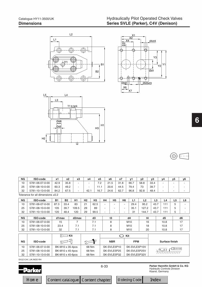
Dimensions
Tolerance for all dimensions ±0.2
NG ISO-code x1 x2 x3 x4 x5 x6 x7 y1 y2 y3 y4 y5 y610 5781-06-07-0-00 42.9 35.8 - - 7.2 21.5 31.8 66.7 58.8 33.4 - - -25 5781-08-10-0-00 60.3 49.2 - - 11.1 20.6 44.5 79.4 73 39.7 - - -32 5781-10-13-0-00 84.2 67.5 - 42.1 16.7 24.6 62.7 96.8 92.8 48.4 - - -
NG ISO-code B1 B2 H1 H2 H3 H4 H5 H6 L1 L2 L3 L4 L5 L610 5781-06-07-0-00 87.3 33.4 83 21 62.5 - - - 29.4 95.2 43.7 111 5 -25 5781-08-10-0-00 105 39.7 109.5 29 89 - - - 35.1 127.2 43.7 111 5 -32 5781-10-13-0-00 120 48.4 120 29 99.5 - - - 31 144.7 43.7 111 5 -
NG ISO-code d1max d2max d3 t3 d4 t4 d5 d610 5781-06-07-0-00 15 7 7.1 8 M10 16 10.8 1725 5781-08-10-0-00 23.4 7.1 7.1 8 M10 18 10.8 1732 5781-10-13-0-00 32 7.1 7.1 8 M10 20 10.8 17
NG ISO-code NBR FPM Surface finish
10 5781-06-07-0-00 BK-M10 x 35-4pcs 68 Nm SK-SVLE5P10 SK-SVLE5P10V25 5781-08-10-0-00 BK-M10 x 45-4pcs 68 Nm SK-SVLE5P25 SK-SVLE5P25V32 5781-10-13-0-00 BK-M10 x 45-6pcs 68 Nm SK-SVLE5P32 SK-SVLE5P32V

6-34
SVLE-C4V_UK.INDD RH
Catalogue HY11-3500/UK
Parker Hannifin GmbH & Co. KGHydraulic Controls DivisionKaarst, Germany
6
Notes

6-35
Check ValvesAccessories
Catalogue HY11-3500/UK
Parker Hannifin GmbH & Co. KGHydraulic Controls DivisionKaarst, Germany
access06.INDD RH
6
Plugs
DescriptionThreaded cable
jointBody colour
codingFigures
switchingOrder no.
Plug DIN 43650, design type AF, protection class IP 65Voltages up to 250 V
PG 9black, Bgrey, A
Fig. 150017105001711
PG11black, Bgrey, A
Fig. 150017165001717
Other plugs on request

6-36
access06.INDD RH
Catalogue HY11-3500/UK
Parker Hannifin GmbH & Co. KGHydraulic Controls DivisionKaarst, Germany
6
Notes