catalogue f160.en :: b series, connectors for rail …catalogue f160.en :: b series, connectors for...
TRANSCRIPT

1 Connnectors
More information here: schaltbau-gmbh.com
IndexCatalogue F160.en :: B Series, Connectors for rail vehicles 1
Connectors for rail vehicles, Series B 2
Features 2
Standards 2
Quality and Safety 2
Stock items, special variants 2
Application Interlocking circuit to protect personnel from contact with high voltages 3
Assembled as set Pre-assembled single and double ended connecting cables 3
Specifications 4
Specifications 5
Overview B series 6
B ST Pg42, B ST Pg48 Plug for ferrule with Pg42 / Pg48 thread, housing Part 1 8
B VS Pg42/25-29, B VS Pg42/30-35, B VS Pg48/36-41, B VS Pg48/42-48 Ferrule with P,G thread housing Part 2 8
B ST M42, B ST M48, B ST M50 Plug for ferrule with M40x1.5 / M48x3 /M50x1.5 thread, housing Part 1 9
B VS M40/xx-xx Cable gland with metric thread, housing Part 2 9
B DL Pg29 Receptacle with 90° cable entry for ferrule with Pg29 thread, housing part 1 10
B DL Receptacle long, housing part 1 10
B DK R Receptacle short with contact bridge on cover, housing part 1 10
B DK Receptacle short, housing part 1 11
B BD Dummy receptacle, housing part 1 11
B VD Pg48, B VD M50 Cover, housing part 2 11
Pin and socket inserts 12
Contacts Crimp (pin/socket), for B E-59P+PE und B E-59S+PE only 13
AWZ-x Extraction tool 13
CWZ-600-1 Crimp tool 13
Mounting template 13
Assembly Receptacle B DL R with insert B E-3S+PE+4 /M / 150 14
Pre-assembled cables Signle and double ended connector cables 14
Installation and safety instructions 15
Electrical Components and Systems for Railway Engineering and Industrial Applications 16
B Series
Connectors for rail vehicles
Catalogue F160.en
Catalogue F160.en :: B Series, Connectors for rail vehicles

2
Subject to technical alterations
The connectors, series B, have been designed especially for the demand-ing railcar environment. They are superbly suited for power and control circuits on road and rail vehicles alike.
● Rugged design ● Universally usable connectors for power
and control circuits ● Easy replacement of components ● Easy assembly resulting in short assembly times ● Mechanically locking connector
● IEC 61984: Connectors - Safety requirements and tests
● DIN EN 60529: Degrees of protection provided by enclosures (IP Code)
● IEC 60664-1: Insulation coordination for equipment within low-voltage systems
Presented in this catalogue are only stock items that can be supplied in short delivery time.
The power connectors can be used in applications up to 400 V respec-tively. By adding control contacts, protection circuits may be realised such as the interlocking circuit shown in the diagram below.
Special variantsIf you need a special variant feel free to contact us. Maybe the type of connector you are looking for is among our many special designs. If not, we can also supply customized designs. In this case, however, minimum order quantities apply.
Connectors for rail vehicles, Series B
Features Standards
Stock items, special variants
Rail vehicles in good hands – with Schaltbau connectors
Quality and Safety
The development, manufacture and assembly of our products are subject to the quality management provisions of DIN EN ISO 9001 and IRIS (Interna-tional Railway Industry Standard).
Continuous testing guarantees consistently high quality. Your benefit: Great performance at low operating costs. Maximum operating reliability and long lifetime of your rolling stock.
3
221
1
22
22
1
6
144
33
1
6
144
55
33
633
44
55
633
44
55
55
1
6
1
44
55
33
55
633
44
22
22
22
Subject to technical alterations
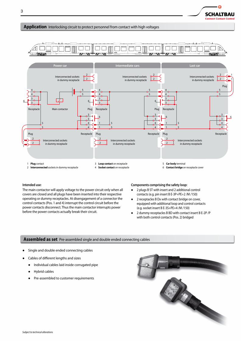
Intended use:The main contactor will apply voltage to the power circuit only when all covers are closed and all plugs have been inserted into their respective operating or dummy receptacles. At disengagement of a connector the control contacts (Pos. 1 and 4) interrupt the control circuit before the power contacts disconnect. Thus the main contactor interrupts power before the power contacts actually break their circuit.
Interconnected sockets in dummy receptacle
Receptacle Main contactor Plug Receptacle Plug Receptacle
Plug
Plug Receptacle Plug Receptacle Plug Receptacle
1 Plug contact 3 Loop contact on receptacle 5 Car body terminal2 Interconnected sockets in dummy receptacle 4 Socket contact on receptacle 6 Contact bridge on receptacle cover
Components comprising the safety loop: ● 2 plugs B ST with insert and 2 additional control
contacts (e.g. pin insert B E-3P+PE+2 /M /150) ● 2 receptacles B Dx with contact bridge on cover,
equipped with additional loop and control contacts (e.g. socket insert B E-3S+PE+4 /M /150)
● 2 dummy receptacles B BD with contact insert B E-2P /P with both control contacts (Pos. 2) bridged
Interconnected sockets in dummy receptacle
Interconnected sockets in dummy receptacle
Interconnected sockets in dummy receptacle
Interconnected sockets in dummy receptacle
Interconnected sockets in dummy receptacle
Application Interlocking circuit to protect personnel from contact with high voltages
● Single and double ended connecting cables
● Cables of different lengths and sizes
● Individual cables laid inside corrugated pipe
● Hybrid cables
● Pre-assembled to customer requirements
Assembled as set Pre-assembled single and double ended connecting cables
Power car Last carIntermediate cars

4
Subject to technical alterations
Specifications Series B
Series B, number of contacts max. 3+PE + 2 pole / 3+PE + 4 pole 4 + 29 pole
Inserts Pin insert Socket insert Dummy insert
B E-3P+PE+2 /M --- ---
--- B E-3S+PE+2 /M
B E-2P /P
B E-4P+29 /ML B E-4S+29 /ML
---
Contact arrangement
6 7
1 3 2
Stifteinsatz B E-3P+PE+2/M 1-1490-308440
4 67
891
3 2
B E-3P+PE+2/M1-1490-308440
4
Kontaktbrücke im Deckel
Kontaktbrücken im Buchseneinsatz 29 28 27 26 25 2423 22 21 20 19 18 17
16 15 149 8 7 610111213
5 4 3 2 1
D C B A
StifteinsatzB E-4P+29/ML1-1490-310590
Contact identification marked on insert: Socket insert: Rear view Pin insert: Front view
6 7
1 3 2
Stifteinsatz B E-3P+PE+2/M 1-1490-308440
4 67
891
3 2
B E-3P+PE+2/M1-1490-308440
4
Contact bridge on receptacle cover
Contacts brigded in socket insert29 28 27 26 25 24
23 22 21 20 19 18 17
16 15 149 8 7 610111213
5 4 3 2 1
D C B A
StifteinsatzB E-4P+29/ML1-1490-310590
Main contacts Max. rated current of individual contact Rated voltage Contact type Terminals
3 x 200 A400 / 230 V
VScrews M10x25
4 x 100 A60 / 25 V
WScrews M8x20
PE contact* Contact type Terminal
VScrew M10x25
------
Control contacts Max. rated current of individual contact Rated voltage Contact type Terminals Crimp type 0.75 mm² ... 1.00 mm² 1.50 mm² 2.50 mm²
2 x 35 A400 / 230 V
CScrews M5x10
--- --- ---
29 x 20 A60 / 25 V
HSolder, 4 mm² max.
--- --- ---
Loop contacts (socket insert only) Max. rated current of individual contact Rated voltage Contact type Terminals
2 x 16 A60 / 25 V
---Screws M5x10
------------
Contact resistance < 10 mΩ < 10 mΩ
Insulation resistance > 100 MΩ > 100 MΩ
Operating temperature ** -40° C ... +85° C -40° C ... +85° C
Degree of protection when mated or locked (EN 60529) IP54 IP54
Mechanical endurance (housing part 1) (IEC 60512-5, test 9a)
1,000 1,000
Materials Housing Colour Inserts, Seals Contacts Finish
Die-cast aluminiumRAL 7031 (blue grey)
Thermoplastic / ThermosetPerbunan, Neoprene
Copper, crimpableAg
Approvals
* PE = protective earthing contact** Operating temperatures exceeding 25° C account for lower current ratings!

5
Subject to technical alterations
Series B, number of contacts max. 28 pole + PE 29 pole 59 pole + PE
Inserts Pin insert Socket insert Dummy insert
B E-28P+PE /M B E-28S+PE /M
---
B E-29P /M B E-29S /M
---
B E-59P+PE /Cxx B E-59S+PE /Cxx
---
Contact arrangement
Stifteinsatz B E-28P+PE 1-1490-985309
5 4 3 2 111 10 9 8 7 6
18 17 16 15 14 13 1224 23 22 21 20 19
29 28 26 25
Stifteinsatz B E-29P /M 1-1490-315528
5 4 3 2 111 10 9 8 7 6
18 17 16 15 14 13 12 24 23 22 21 20 19
29 28 27 26 25 87654321
StifteinsatzB E-59+PE1-1490-237871
UTSRPNMLKHGFEDCBA
Contact identification marked on insert: Socket insert: Rear view Pin insert: Front view
Stifteinsatz B E-28P+PE 1-1490-985309
5 4 3 2 111 10 9 8 7 6
18 17 16 15 14 13 1224 23 22 21 20 19
29 28 26 25
Stifteinsatz B E-29P /M 1-1490-315528
5 4 3 2 111 10 9 8 7 6
18 17 16 15 14 13 12 24 23 22 21 20 19
29 28 27 26 25 87654321
StifteinsatzB E-59+PE1-1490-237871
UTSRPNMLKHGFEDCBA
Main contacts Max. rated current of individual contact Rated voltage Contact type Terminals
------------
------------
------------
PE contact* Contact type Terminal
CScrews M5x10
------
------
Control contacts Max. rated current of individual contact Rated voltage Contact type Terminals Crimp type 0.75 mm² ... 1.00 mm² 1.50 mm² 2.50 mm²
28 x 25 A110 V
CScrews M5x10
--- --- ---
29 x 25 A110 V
CScrews M5x10
--- --- ---
59 x 16 A400 / 230 V
HCrimp
--- (... /C1,5) (... /C2,5)
Loop contacts (socket insert only) Max. rated current of individual contact Rated voltage) Contact type Terminals
------------
------------
------------
Contact resistance < 10 mΩ < 10 mΩ < 10 mΩ
Insulation resistance > 100 MΩ > 100 MΩ > 100 MΩ
Operating temperature ** -40° C ... +85° C -40° C ... +85° C -40° C ... +85° C
Degree of protection when mated or locked (EN 60529) IP54 IP54 IP54
Mechanical endurance (housing part 1) (IEC 60512-5, test 9a)
1,000 1,000 1,000
Materials Housing Colour Inserts, Seals Contacts Finish
Die-cast aluminiumRAL 7031 (blue grey)
Thermoplastic / ThermosetPerbunan, Neoprene
Copper, crimpableAg
Die-cast aluminiumRAL 7031 (blue grey)
Thermoplastic / ThermosetPerbunan, Neoprene
Copper, crimpableAg or Ni
Approvals
* PE = protective earthing contact** Operating temperatures exceeding 25° C account for lower current ratings!
Specifications Series B

6
Housing part 2 Housing part 1 Contact InsertO
verv
iew
::
B Se
ries –
Plu
g
Overview B series
B E-3P+PE+2 /M /150 Pin insert(page 12)
B E-4P+29 /ML Pin insert(page 12)
B E-28P+PE /M Pin insert(page 12)
B E-29P /M Pin insert(page 12)
B ST Pg42 Plug
(page 8)
B ST M40 Plug
(page 9)
B ST M48 Plug
(page 9)
B ST M50 Plug
(page 9)
B ST Pg48 Plug
(page 8)
B VS Pg42/25-29 Ferrule
(page 8)
B VS Pg42/30-35 Ferrule
(page 8)
B VS M48/25-30 Cable gland
(page 9)
B VS Pg48/36-41 Ferrule
(page 8)
B VS Pg48/42-48 Ferrule
(page 8)
SHC-1,50-Ag or
SHC-2,50-Ni Pin contact, crimp
(page 13)
B E-59P+PE /C1,5 B E-59P+PE /C2,5
Pin insert including crimp contacts(page 12)
B E-59P+PE Pin insert without crimp contacts
(page 12)

7
Insert Contact Housing part 2Housing part 1
Ove
rvie
w :
: B
Serie
s – R
ecep
tacl
e
Overview B series
B E-3S+PE+4 /M /150 Socket insert
(page 12)
B E-2P /P Dummy insert
(page 12)
B E-4S+29 /ML Socket insert
(page 12)
B E-29S /M Socket insert
(page 12)
B E-28S+PE /M Socket insert
(page 12)
B DL Pg29 Receptacle(page 10)
B DL Receptacle long
(page 10)
B DL R Receptacle (contact bridge on cover)
(page 10)
B DK Receptacle short
(page 11)
B BD Dummy receptacle
(page 11)
BHC-1,50-Ag or
BHC-2,50-Ni Socket contact, crimp
(page 13)
B E-59S+PE /C1,5 B E-59S+PE /C2,5
Socket insert including crimp contacts(page 12)
B VD Pg48 Cover with Pg48 thread
(page 11)
B VD M50 Cover with M50 thread
(page 11)
B E-59S+PE Socket insert without crimp contacts
(page 12)
8Pg
42
Ø46
±0.3
Ø49
7445
Figure A
Ø46
±0.3
Pg42
Ø49
7445
Figure B
Ø49
Ø80
Pg48
(Ø61
)
10264
Figure C
Pg48
(Ø61
)
Ø80
Ø49
10264
Figure D
136
160
54~
98
90
Pg42Ø36
M5
90
Pg48Ø 36
M5
Figure A Figure B
Subject to technical alterationsDimensions in mm / Subject to technical alterations
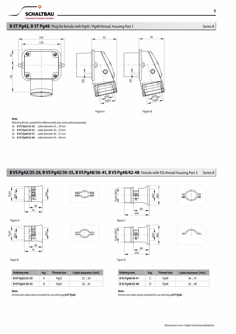
Series BB ST Pg42, B ST Pg48 Plug for ferrule with Pg42 / Pg48 thread, housing Part 1 Series B
B VS Pg42/25-29, B VS Pg42/30-35, B VS Pg48/36-41, B VS Pg48/42-48 Ferrule with P,G thread housing Part 2 Series B
Note:Matching ferrule, available for different cable sizes, to be ordered separately:1x B VS Pg42/25-29 , cable diameter 25 ... 29 mm1x B VS Pg42/30-35 , cable diameter 30 ... 35 mm1x B VS Pg48/36-41 , cable diameter 36 ... 41 mm1x B VS Pg48/42-48 , cable diameter 42 ... 48 mm
Ordering code Fig. Thread size Cable diameter [mm]
B VS Pg42/25-29 A Pg42 25 ... 29
B VS Pg42/30-35 B Pg42 30 ... 35
Ordering code Fig. Thread size Cable diameter [mm]
B VS Pg48/36-41 C Pg48 36 ... 41
B VS Pg48/42-48 D Pg48 42 ... 48
Note:Ferrule and cable clamp intended for use with plug B ST Pg42.
Note:Ferrule and cable clamp intended for use with plug B ST Pg48.

9
Ø36
M48
x3
8064
136
160
54~
98
90
M5
90
M5
90
M5
Figure A Figure B Figure C
M40x1.5Ø36
M48x3Ø36
M50x1.5Ø36
Subject to technical alterationsDimensions in mm / Subject to technical alterations
Series BB ST M42, B ST M48, B ST M50 Plug for ferrule with M40x1.5 / M48x3 /M50x1.5 thread, housing Part 1 Series B
B VS M40/xx-xx Cable gland with metric thread, housing Part 2 Series B
Ordering code Thread size Cable diameter [mm]
B VS M48/25-30 M48x3 25 ... 30
Note: ● Cable glands B VS M48/25-30 for plugs B ST M48 ● Cable glands M40x1,5 for plugs B ST M40 and
cable glands M50x1,5 with metric thread for plugs B ST M50 are not available. Please order separately.
Note: ● Cable glands are only available for plugs B ST M48 (figure B). ● Cable glands for plugs B ST M40 (figure A) and B ST M50 (figure C)
are not available. Please order separately.
10
176
132Bushing
Gasket
Screw-typeblank cap
146
Ø6.5
118
132
150
94 x
122
45
97
51Pg29 165
202
128
M54x
176
132
146
Ø6.5
118
132
150
94 x
122
9151
165
202
128
M54x
Gasket
176
132
146
Ø6.5
118
132
150
94 x
122
3951
165
202
128
M54x
Gasket
Subject to technical alterationsDimensions in mm / Subject to technical alterations
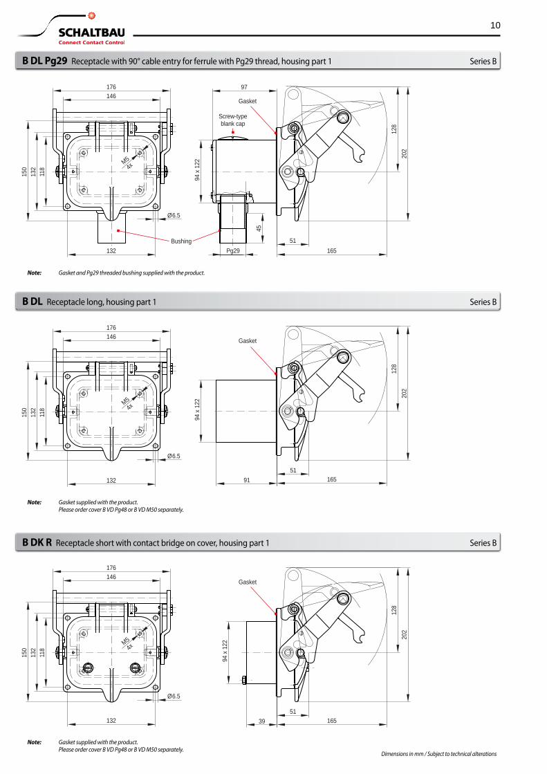
B DL Pg29 Receptacle with 90° cable entry for ferrule with Pg29 thread, housing part 1 Series B
B DL Receptacle long, housing part 1 Series B
B DK R Receptacle short with contact bridge on cover, housing part 1 Series B
Note: Gasket supplied with the product. Please order cover B VD Pg48 or B VD M50 separately.
Note: Gasket supplied with the product. Please order cover B VD Pg48 or B VD M50 separately.
Note: Gasket and Pg29 threaded bushing supplied with the product.
11
176
132
146
Ø6.5
118
132
150
94 x
122
3951
165
202
128
M54x
Gasket
176
132
146
Ø6.5
104
118
150
94 x
122
3951
165
202
128
M54x
Gasket
100
72
Ø52
.5
Pg48
14+2
(21)
(30)
Ø5.8
4x
100
72
Ø52
.5
M50
14+2
(21)
(30)
Ø5.8
4x
Subject to technical alterationsDimensions in mm / Subject to technical alterations
Series B
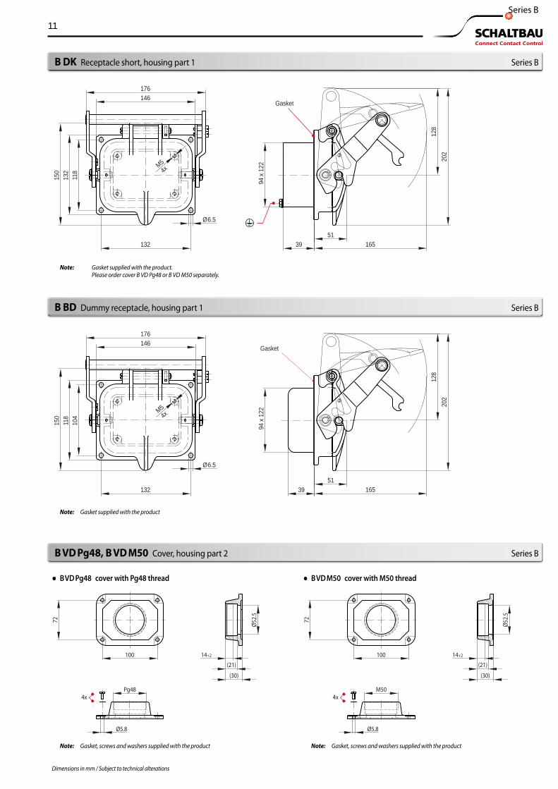
B DK Receptacle short, housing part 1 Series B
B BD Dummy receptacle, housing part 1 Series B
Note: Gasket, screws and washers supplied with the productNote: Gasket, screws and washers supplied with the product
Note: Gasket supplied with the product
Note: Gasket supplied with the product. Please order cover B VD Pg48 or B VD M50 separately.
B VD Pg48, B VD M50 Cover, housing part 2 Series B
● B VD Pg48 cover with Pg48 thread ● B VD M50 cover with M50 thread

12
1 2 3 4 5
109876 11
1712 13 14 15 16 18
2322212019 24
25 26 27 28 292526272829
192021222324
12131415161718
67891011
12345
72
100
72
100
Subject to technical alterationsDimensions in mm / Subject to technical alterations
Number of contacts max. 59 pole + PE
Inserts Pin insert Socket insert Dummy insert
B E-59P+PE B E-59S+PE
---
B E-59P+PE /C1.5 or B E-59P+PE /C2.5 B E-59S+PE /C1.5 or B E-59S+PE /C2.5
---Contact arrangementContact identification marked on insert:Socket insert: Rear view Pin insert: Front view 8
7654321
UTSRPNMLKHGFEDCBA
Stifteinsatz
87654321
UTSRPNMLKHGFEDCBA
Stifteinsatz
Main contacts Contact type TerminalsPE contact * Contact type Terminals
--- ------ ---
--- ------ ---
Control contacts Contact type Terminals Crimp type
for contacts size H ** (Crimp) **
1.5 mm² or 2.5 mm²
H *** Crimp
1.5 mm² or 2.5 mm²* PE = protective earthing contact ** Insert without contacts, please order separetely *** Contacts included in delivery
Inserts
Number of contacts max. 3 + PE + 2 pole / 3 + PE + 4 pole 4 + 29 pole
Inserts Pin insert Socket insert Dummy insert
B E-3P+PE+2 /M B E-3S+PE+2 /M
---
--- B E-3S+PE+4 /M
B E-2P /P
B E-4P+29 /ML B E-4S+29 /ML
---Contact arrangementContact identification marked on insert:Socket insert: Rear view Pin insert: Front view
Stifteinsatz
67
13 2
4
Contact bridge on receptacle cover
Contacts brigded in socket insertStifteinsatz
67
891
3 24
Contact bridge on receptacle cover
Contacts brigded in socket insertStifteinsatz
29 28 27 26 25 2423 22 21 20 19 18 17
16 15 149 8 7 610111213
5 4 3 2 1
D C B A
Contact bridge on receptacle cover
Contacts brigded in socket insert
Main contacts Contact type TerminalsPE contact * Contact type Terminals
V Screws M10x25
V Screws M10x25
W Screws M8x20
--- ---
Control contacts Contact type Terminals Crimp type
C Screws M5x10
---
C Screws M5x10
---
Number of contacts max. 28 pole + PE 29 pole
Inserts Pin insert Socket insert Dummy insert
B E-28P+PE /M B E-28S+PE /M
---
B E-29P /M B E-29S /M
---Contact arrangementContact identification marked on insert:Socket insert: Rear view Pin insert: Front view
5 4 3 2 111 10 9 8 7 6
18 17 16 15 14 13 1224 23 22 21 20 19
Stifteinsatz
29 28 26 25
5 4 3 2 111 10 9 8 7 6
18 17 16 15 14 13 1224 23 22 21 20 19
29 28 27 26 25
StifteinsatzMain contacts Contact type TerminalsPE contact * Contact type Terminals
--- ------ ---
--- ------ ---
Control contacts Contact type Terminals Crimp type
C Screws M5x10
---
C Screws M5x10
---
Pin and socket inserts Series B
Pin insert Socket insert
Note: Accessories such as screws, lugs and crimp contacts are supplied with the product.

13
Ø1.58 Ø3.76 Ø3.76 Identification Identification Wire gauge Ø1.58 Wire gauge
L2 L1
Ø1.6 Ø3.2 Ø3.5 Wire gauge Ø1.6 Wire gauge
L2 L1
Ø2.3 Ø5.15 Ø5.15 Identification Identification Wire gauge Wire gauge Ø2.3
L2 L1
Ø3 Ø7.2 Ø7.2 Identification Identification Wire gauge Wire gauge Ø3
L2 L1
Ø6.5
132
118
124
96
R20
Subject to technical alterationsDimensions in mm / Subject to technical alterations
CWZ-600 Crimp tool Series B
Contacts SHC-x, BHC-x Crimp contacts (pin/socket):
* For AWG sizes refer to the conversion table on our home page http://www.schaltbau-gmbh.com/files/awg-electrical-wire-conversion-table.pdf
Contacts Crimp (pin/socket), for B E-59P+PE und B E-59S+PE only Series B
AWZ-x Extraction tool CWZ-600-1 Crimp tool Series B
Pin contactOrdering code L1 IdentificationSHC-1.50-Ag 43.6 2 groovesSHC-2.50-Ni 43.6 3 grooves
Socket contactOrdering code L2 IdentificationBHC-1.50-Ag 42.4 2 groovesBHC-2.50-Ni 42.4 3 grooves
SpecificationWire gauge* Rated current1.5 mm² 16 A 2.5 mm² 27.5 A
(Figure reduced in scale) (Figure reduced in scale)
AWZ-C/H Extraction tool for contacts Type C and Type H
CWZ-600-1 Crimp tool for wire gauges* ranging from 0,14 ... 6,00 mm²
Mounting template for all receptacles: ● B DL Pg29 Receptacle for Pg29 threaded ferrule, locked
● B DL Receptacle long
● B DL R Receptacle short with contact bridge in cover
● B DK Receptacle short
● B BD Dummy receptacle
Mounting template Series B

14
L
L1
L
L1
Subject to technical alterationsDimensions in mm / Subject to technical alterations
Assembly Receptacle B DL R with insert B E-3S+PE+4 /M / 150 Series B
Pre-assembled cables Signle and double ended connector cables Series B
Pre-assembled plugs ● Single and double ended connecting cables ● Cables of different lengths and sizes
● Individual cables laid inside corrugated pipe ● Hybrid cables ● Pre-assembled to customer requirements
Do you prefer a pre-assembled connector? Do not hesitate to contact us. We supply on request receptacles and plugs assembled complete with cables or wires to suit the customer‘s specific requirements.
Schaltbau offers a host of cable lengths and wire gauges to suit your application and guarantees a constant high quality of the assembled connectors.
Double ended connector cable
Single ended connector cable
Flat rubber gasket
Socket insertB E-3S+PE+4 /M / 150
Insulatoron cover
Contact bridge
Loop contact Contact travel approx. 3 mm
Receptacle with contact bridge on cover B DL R
Lug 70 mm²4 lugs 70 mm² for terminal M10 loosely enclosed.Terminal type: solder.Note: Slide shrink fitting tubings over all lugs!
Main contactTerminal M10
Auxiliary contactTerminal M5
PE conductor connected to housing Hex screw M6 x 8
Connecting lead H07-K4 4 mm² pre-assembled
Lug 10 mm² for connecting protective earth conductor to housing
Lug 4 mm² terminal M5 Terminal type: solder/crimp
Mounting 4x M5 screw Socket insert in housing
Loop contact Contact travel approx. 3 mm
Receptacle (Sectional view)Socket insert: front view
Socket insert: rear view

15
Subject to technical alterationsDimensions in mm / Subject to technical alterations
Installation and safety instructions Series B
Visual inspectionsBe sure to make visual inspections regularly. Improper handling of the connector, e.g. when hitting the floor with some impact, can result in breakage, visible cracks and deformation.
Defective and/or leaky parts must be replaced instantaneously!
The UIC Series inter-car jumpers dealt with in this catalogue are in-tended for use with low-voltage systems and special installations. They are designed and tested in compliance with the generally recognised state of the art. However, the improper use, operation, handling,
maintenance of or tampering with electric equipment can cause serious or fatal injury to the user or others, and the appliance or other property can be damaged.
Electrical hazards: Any exposure to the connector‘s live parts. Risk of electrical shock! Observe all applicable national provisions, all safety, accident prevention and environmental regulations as well as the recognized technical rules for safe and proper working.
Due to our continuous improvement programme, the design of our products can be modified at any time. So some features may differ from the descriptions, specifi-cations and drawings in the catalogue. You can download the latest update of the catalogue at
schaltbau.info/download1en. The updated catalogue renders the previous issue invalid.
● Only authorized and trained personnel are allowed to plan and carry out all mechanical and electrical installations, transport, commissioning, as well as maintenance and repair work.
● This applies to the observation of the general installation and safety regulations for low-voltage systems as well as the proper use of tools approved for this purpose. Electric equipment requires protection from moisture and dust during installation, operation and storage.
● Electrical hazards: Any exposure to the connector‘s live parts. Risk of electrical shock!
● Work on electric equipment may only be performed by a qualified electrician or trained personnel working under the direction and supervision of a qualified electrician according to the applicable rules of electrical engineering.
● Observe all applicable national provisions, all safety, accident preven-tion and environmental regulations as well as the recognized technical rules for safe and proper working.
● Carry out regular inspections of all protection and safety devices to see if they work properly.
● Work on electric equipment may only be performed by a qualified elec-trician or trained personnel working under the direction and supervi-sion of a qualified electrician according to the applicable rules of electrical engineering.
● The connectors supply power and signals. They are intended for plug-in and detachable connections of components, devices and systems only.
● In order to comply with IEC 61984 make sure that always the live side of the connector – no matter whether plug or receptacle – is fitted with socket contacts. Crimp connections have to be manufactured according to IEC 60352-2 – Solderless Connections.
● Make sure that there is no undue strain, pressure, flexing and torsion on the cable connection.
● For optimum protection of the cable connection make sure the connector is supplied with a strain relief.
● According to IEC 61984 connectors used as intended must not be engaged or disengaged when live or under load.
● Crimp connections have to be manufactured according to IEC 60352-2 – Solderless Connections.
● When disengaging a connector, pull the plug and never the cable. ● A connector that does not engage easily requires special attention:
Check for the correct orientation, pollution or if contacts got bent. Remedy the cause without delay. Never use force! The connector should always engage easily.
● In order to meet the requirements of the protection class and to protect the connectors against the entry of dirt or moisture, make sure that, when not mated,
● the plug is always inserted into a dummy receptacle ● the hinged lid of receptacles is closed, according to its
intended use ● Use the connector only according to its intended use. Replace or
repair damaged parts exclusively with original parts. Any other usage of or tampering with the connector is considered contrary to its intended use. No liability is assumed for damages and accidents caused due to non-compliance with the instructions or improper use of the connector.
● The connectors are constructed for specific ambient conditions. Operate the connectors only under the ambient conditions, like temperature ranges and IP protection classes as defined in our catalogue on page 3 “Specifications“.

with compliments:Schaltbau GmbHFor detailed information on our products and services visit our website – or give us a call!
Schaltbau GmbH Hollerithstrasse 5 81829 Munich Germany
Phone +49 89 9 30 05-0 Fax +49 89 9 30 05-350 Internet www.schaltbau-gmbh.com e-Mail [email protected]
Connectors
■ Connectors manufactured to industry standards
■ Connectors to suit the special requirements of communications engineering (MIL connectors)
■ Charging connectors for battery-powered machines and systems
■ Connectors for railway engineering, including UIC connectors
■ Special connectors to suit customer requirements
Snap-action switches ■ Snap-action switches with positive opening operation
■ Snap-action switches with self-cleaning contacts
■ Enabling switches
■ Special switches to suit customer requirements
Contactors ■ Single and multi-pole DC contactors
■ High-voltage AC/DC contactors
■ Contactors for battery powered vehicles and power supplies
■ Contactors for railway applications
■ Terminal bolts and fuse holders
■ DC emergency disconnect switches
■ Special contactors to suit customer requirements
Electrics for rolling stock
■ Equipment for driver's cab
■ Equipment for passenger use
■ High-voltage switchgear
■ High-voltage heaters
■ High-voltage roof equipment
■ Equipment for electric brakes
■ Design and engineering of train electrics to customer requirements
Electrical Components and Systems for Railway Engineering and Industrial Applications
RoHS2011/65/EC
Schaltbau
Qua
lity y
ou can count on
Schaltbau
Qua
lity y
ou can count on
Schaltbau GmbH manufactures in
compliance with RoHS.
The production facilities of Schaltbau GmbH have been IRIS certified since
2008.
Certified to DIN EN ISO 14001
since 2002. For the most recent certificate visit
our website.
Certified to DIN EN ISO 9001
since 1994. For the most recent certificate visit
our website.
Electrical Components and Systems for Railway Engineering and Industrial Applications
F1896/1802/0 Printed in Germany
Subject to change!
For updated product information visit www.schaltbau-gmbh.com