catalogue - brian perry contiguous piles • secant piles • continuous flight auger piles...
TRANSCRIPT
2
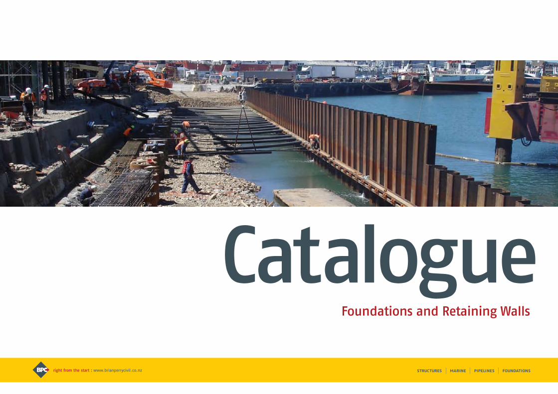
CatalogueFoundations and Retaining Walls

Contents
Why Choose Brian Perry Civil? 1 - 4
Driven Piles 5 - 10 Bored Piles 11 - 14
Pile Testing 15 - 16 Ground Improvement 17 - 22
Pressure Grouting 23 - 24
Marine and Bridge Foundations 25 - 26
Ground Retention 27 - 30 Cut-off Walls 31 - 32 Plant and Equipment 33 - 34
1
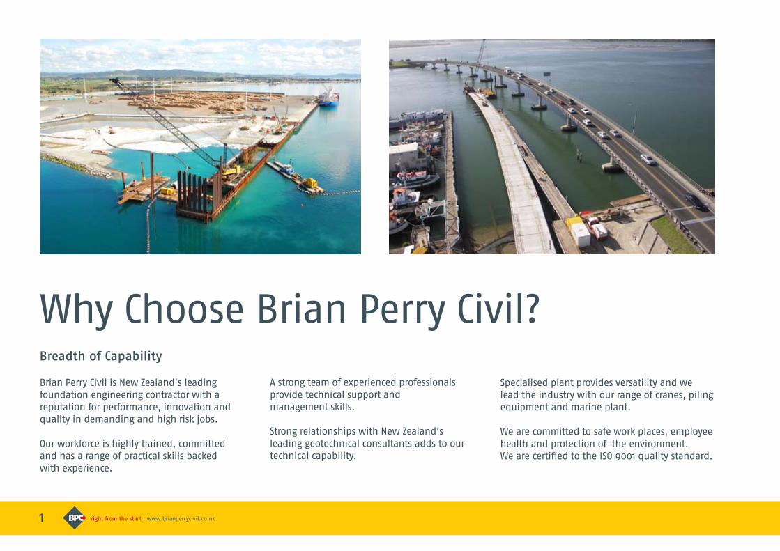
Why Choose Brian Perry Civil?
Brian Perry Civil is New Zealand’s leading foundation engineering contractor with a reputation for performance, innovation and quality in demanding and high risk jobs.
Our workforce is highly trained, committed and has a range of practical skills backed with experience.
A strong team of experienced professionals provide technical support and management skills.
Strong relationships with New Zealand’s leading geotechnical consultants adds to our technical capability.
Breadth of Capability
Specialised plant provides versatility and we lead the industry with our range of cranes, piling equipment and marine plant.
We are committed to safe work places, employee health and protection of the environment. We are certified to the ISO 9001 quality standard.
2
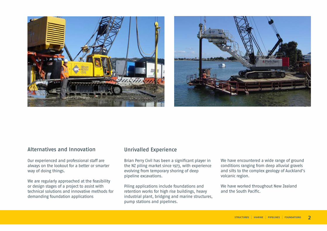
We have encountered a wide range of ground conditions ranging from deep alluvial gravels and silts to the complex geology of Auckland’s volcanic region.
We have worked throughout New Zealand and the South Pacific.
Brian Perry Civil has been a significant player in the NZ piling market since 1973, with experience evolving from temporary shoring of deep pipeline excavations.
Piling applications include foundations and retention works for high rise buildings, heavy industrial plant, bridging and marine structures, pump stations and pipelines.
Unrivalled Experience
Our experienced and professional staff are always on the lookout for a better or smarter way of doing things.
We are regularly approached at the feasibility or design stages of a project to assist with technical solutions and innovative methods for demanding foundation applications
Alternatives and Innovation
2
1
Innovation
3
2
Performance
Certainty of Delivery
Our track record in the construction industry for innovation, performance and certainty of delivery is unrivalled.
This has been recognised with the company receiving multiple New Zealand Contractors’ Federation awards over the years.
Track Record
If we don’t have the experience in house, we team up with those who do.
Some of our most successful projects have been joint ventures with specialist overseas experts where we provide the local knowledge and resources.
Strategic Alliance and Joint Venture
Ownership by The Fletcher Construction Company Ltd provides additional certainty to performance through strength in resources, financial backing and management.
Ownership
Our design / build piling and foundation service, including ground investigation, is offered in conjunction with specialist geotechnical and structural consultants.
We operate in a team environment, either as a team leader or team member.
4
We work successfully in any contractual arrangement, be it competitively bid, main contract, subcontract, negotiated, alliancing, design / build, guaranteed maximum price, fast track or turnkey.
Our success in competitive tendering demonstrates our cost effectiveness.
5
Driven piles take many forms. Selection is determined by location and type of structure, column loads, ground conditions, environmental considerations and material durability.
Brian Perry Civil has experience in all types including:
Displacement Piles
• Timber piles
• Steel H piles
• Precast concrete piles
• Steel tubes – top and bottom driven
• Raked or vertical
Driven cast-in-place piles
• Vibroset piles
Sheet Piles
• For marine and land-based
retaining structures
Piling HammersOur extensive piling hammer range includes:
Impact hammers
Used to fully drive or finish displacement piles in a range of conditions and to drive sheet piles in hard ground.
We offer accelerated hydraulic hammers with their advantages of high capacity, production and efficiency plus a range of traditional drop hammers.
Vibro hammers
Used to advance displacement piles (steel tubes and H sections) in good ground and to drive and withdraw steel casings and sheet piles.
We offer modern hydraulic and electric units with variable frequency to minimise noise and vibration in built-up areas.
Driven PilesApplication
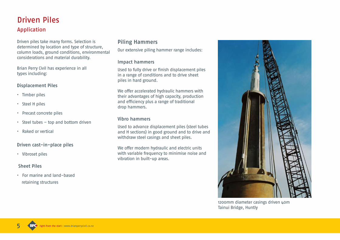
1200mm diameter casings driven 40mTainui Bridge, Huntly
6
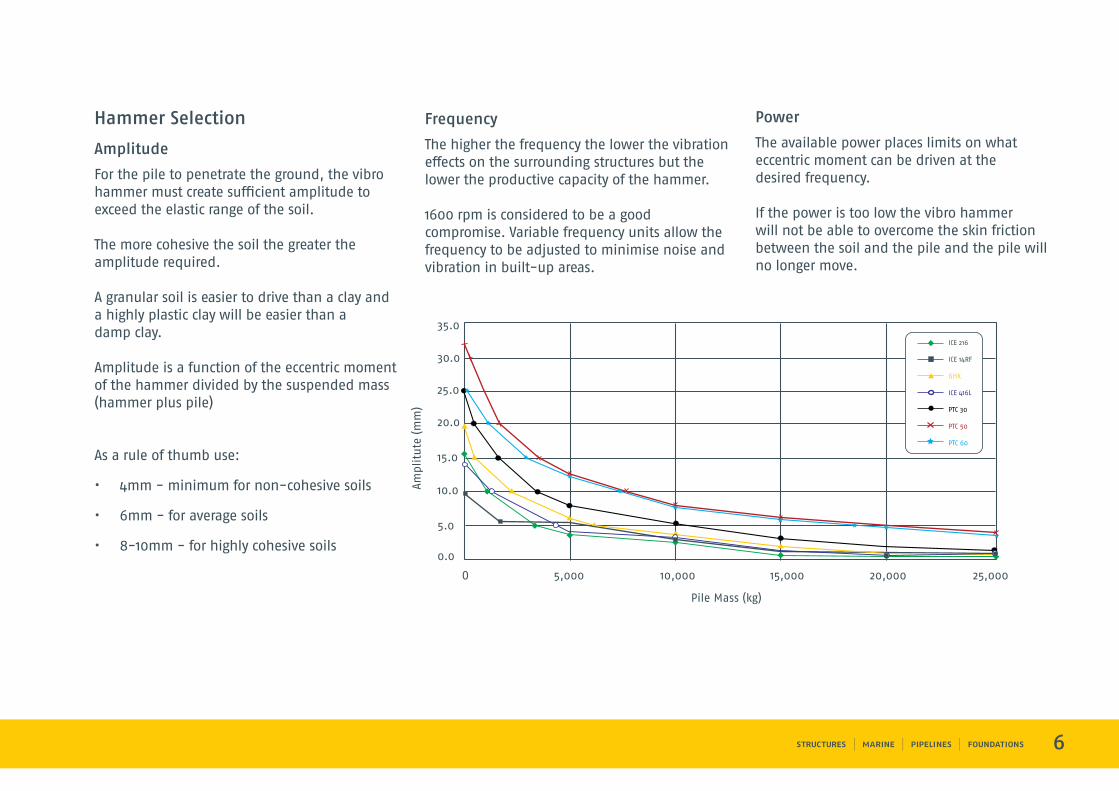
Hammer Selection
Amplitude
For the pile to penetrate the ground, the vibro hammer must create sufficient amplitude to exceed the elastic range of the soil.
The more cohesive the soil the greater the amplitude required.
A granular soil is easier to drive than a clay and a highly plastic clay will be easier than a damp clay.
Amplitude is a function of the eccentric moment of the hammer divided by the suspended mass (hammer plus pile)
As a rule of thumb use:
• 4mm - minimum for non-cohesive soils
• 6mm - for average soils
• 8-10mm - for highly cohesive soils
Frequency
The higher the frequency the lower the vibration effects on the surrounding structures but the lower the productive capacity of the hammer.
1600 rpm is considered to be a good compromise. Variable frequency units allow the frequency to be adjusted to minimise noise and vibration in built-up areas.
Power
The available power places limits on what eccentric moment can be driven at the desired frequency.
If the power is too low the vibro hammer will not be able to overcome the skin friction between the soil and the pile and the pile will no longer move.
O 5,000 10,000 15,000 20,000 25,000
0.0
5.0
10.0
15.0
20.0
25.0
30.0
35.0ICE 216
ICE 14RF
GHK
ICE 416L
PTC 30
PTC 50
PTC 60
Amp
litu
te (
mm
)
Pile Mass (kg)
7
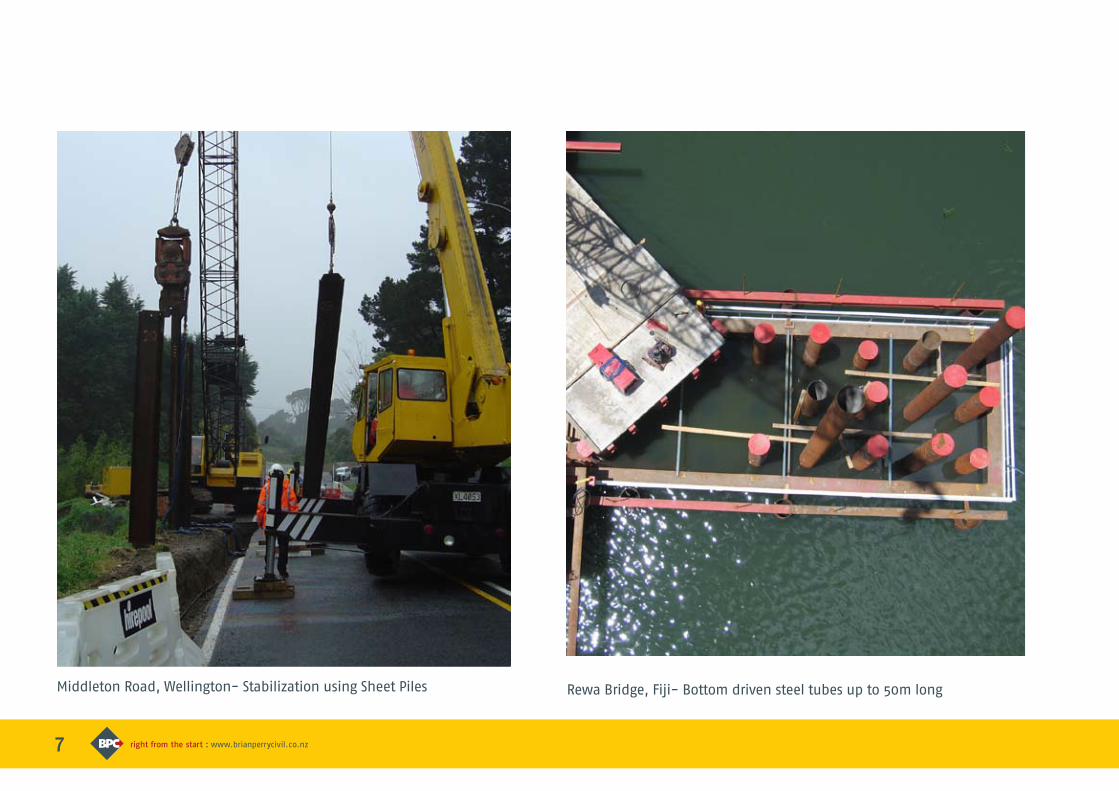
Middleton Road, Wellington- Stabilization using Sheet Piles Rewa Bridge, Fiji- Bottom driven steel tubes up to 50m long
8
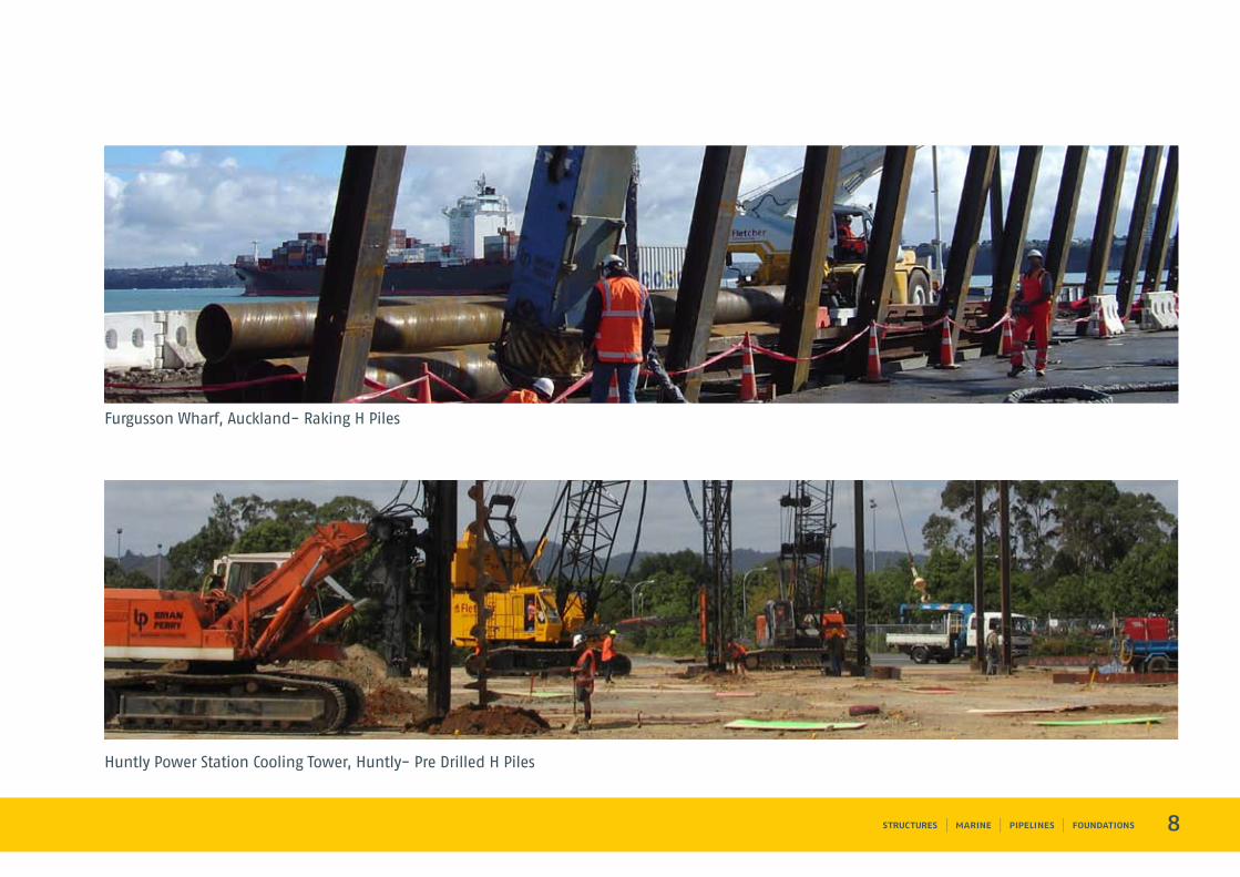
Furgusson Wharf, Auckland- Raking H Piles
Huntly Power Station Cooling Tower, Huntly- Pre Drilled H PilesRewa Bridge, Fiji- Bottom driven steel tubes up to 50m long
9
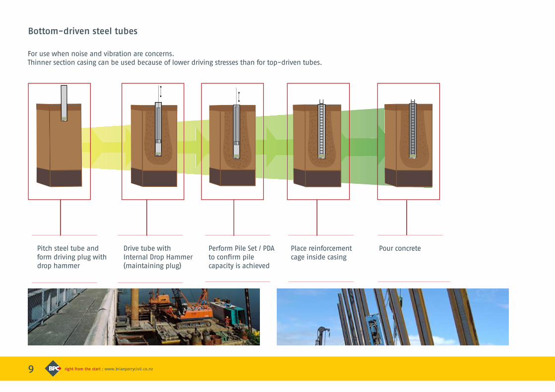
Bottom-driven steel tubes
For use when noise and vibration are concerns. Thinner section casing can be used because of lower driving stresses than for top-driven tubes.
Pitch steel tube and form driving plug with drop hammer
Drive tube with Internal Drop Hammer (maintaining plug)
Perform Pile Set / PDAto confirm pilecapacity is achieved
Place reinforcement cage inside casing
Pour concrete
2
Vibro-set Piles
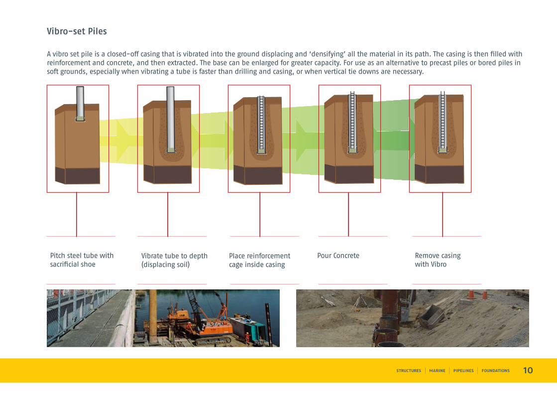
A vibro set pile is a closed-off casing that is vibrated into the ground displacing and ‘densifying’ all the material in its path. The casing is then filled with reinforcement and concrete, and then extracted. The base can be enlarged for greater capacity. For use as an alternative to precast piles or bored piles in soft grounds, especially when vibrating a tube is faster than drilling and casing, or when vertical tie downs are necessary.
10
Pitch steel tube withsacrificial shoe
Vibrate tube to depth(displacing soil)
Place reinforcementcage inside casing
Pour Concrete Remove casingwith Vibro
11
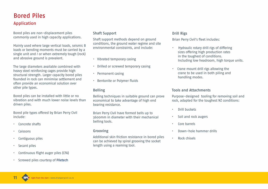
Bored piles are non-displacement piles commonly used in high capacity applications.
Mainly used where large vertical loads, seismic B loads or bending moments must be carried by a single unit and / or when extremely tough (rock) and abrasive ground is prevalent.
The large diameters available combined with heavy steel reinforcing cages provide high structural strength. Larger capacity bored piles founded in rock can minimise settlement and often provide an economical solution over other pile types.
Bored piles can be installed with little or no vibration and with much lower noise levels than driven piles.
Bored pile types offered by Brian Perry Civil include:
• Concrete shafts
• Caissons
• Contiguous piles
• Secant piles
• Continuous flight auger piles (CFA)
• Screwed piles courtesy of Piletech
Drill Rigs
Brian Perry Civil’s fleet includes:
• Hydraulic rotary drill rigs of differing sizes offering high production rates in the toughest of conditions. Including low headroom, high torque units.
• Crane mount drill rigs allowing the crane to be used in both piling and handling modes.
Shaft Support
Shaft support methods depend on ground conditions, the ground water regime and site environmental constraints, and include:
• Vibrated temporary casing
• Drilled or screwed temporary casing
• Permanent casing
• Bentonite or Polymer fluids
Belling
Belling techniques in suitable ground can prove economical to take advantage of high end bearing resistance.
Brian Perry Civil have formed bells up to 3600mm in diameter with their mechanical belling tools.
Grooving
Additional skin friction resistance in bored piles can be achieved by spiral grooving the socket length using a reaming tool.
Bored PilesApplication
Tools and Attachments
Purpose-designed tooling for removing soil and rock, adapted for the toughest NZ conditions:
• Drill buckets
• Soil and rock augers
• Core barrels
• Down-hole hammer drills
• Rock chisels
Standard Diameters Graph
12
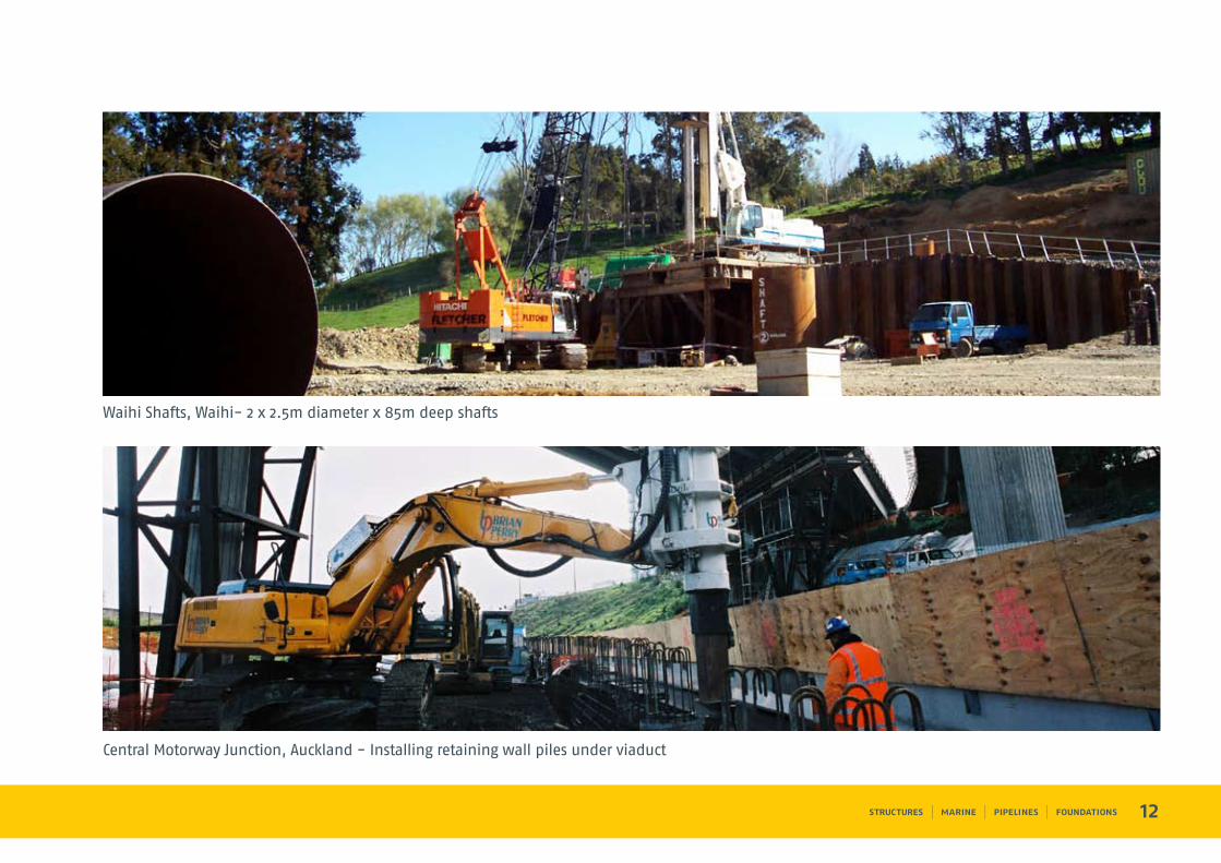
Central Motorway Junction, Auckland - Installing retaining wall piles under viaduct
Waihi Shafts, Waihi- 2 x 2.5m diameter x 85m deep shafts
13
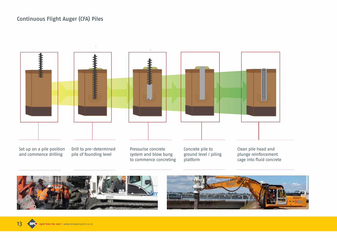
Continuous Flight Auger (CFA) Piles
Set up on a pile position and commence drilling
Drill to pre-determinedpile of founding level
Pressurise concrete system and blow bung to commence concreting
Concrete pile to ground level / piling platform
Clean pile head and plunge reinforcement cage into fluid concrete
14
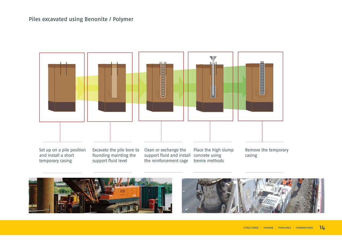
Piles excavated using Benonite / Polymer
Set up on a pile position and install a short temporary casing
Excavate the pile bore to founding mainting the support fluid level
Clean or exchange the support fluid and install the reinforcement cage
Place the high slump concrete using tremie methods
Remove the temporary casing
15
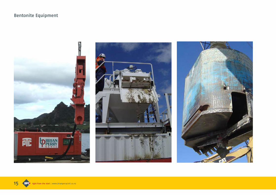
Bentonite Equipment
16
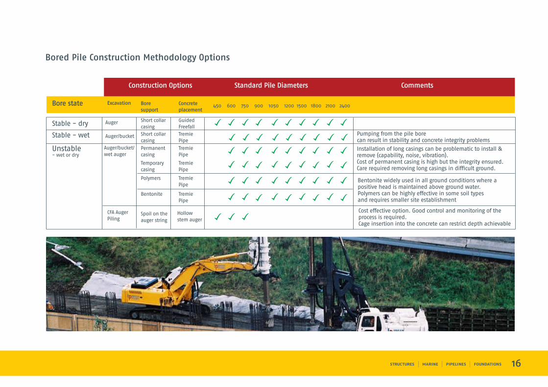
Auger
Auger/bucket
Auger/bucket/wet auger
CFA Auger Piling
Stable - dry
Stable - wet
Unstable- wet or dry
Pumping from the pile bore can result in stability and concrete integrity problems
Installation of long casings can be problematic to install & remove (capability, noise, vibration). Cost of permanent casing is high but the integrity ensured.Care required removing long casings in difficult ground.
Bentonite widely used in all ground conditions where a positive head is maintained above ground water.Polymers can be highly effective in some soil types and requires smaller site establishment
Cost effective option. Good control and monitoring of the process is required. Cage insertion into the concrete can restrict depth achievable
Short collar casing
Short collar casing
Permanentcasing
Spoil on theauger string
Temporarycasing
Polymers
Bentonite
GuidedFreefall
TremiePipe
TremiePipe
Hollowstem auger
TremiePipe
TremiePipe
TremiePipe
Bored Pile Construction Methodology Options
17
Pile testing is an important technique to provide assurance of pile capacity and integrity. It is especially important for cases when:
• Loads are large or critical
• Ground conditions are marginal
or difficult to assess
Structural codes now provide an economic incentive to prove the capacity of piles by allowing a lower design safety factor.
Pile testing offered by Brian Perry Civil include:
Pile Load Testing
• Calculations using the Hiley formula
• PDA (Pile Driving Analyser), a proprietary
dynamic testing system, including
Grlweap wave analysis software
• Traditional static load testing
using kentledge or reaction anchors
• Osterberg cell
Pile Integrity Testing
• Cross Hole Sonic Logging (CSL)
• Pile Echo tester (PET)
Hiley Formula
The Hiley formula assumes the energy of the falling hammer during pile driving is proportional to the energy resisted by the pile. It was intended to be applied to cohesionless, well drained soils or rock.
The method is widely considered to be one of the better formulae of its type.
Comparisons indicate significant differences are possible from the results of a static load test.
Its key advantages are low cost and ease of application but it must be used with high factors of safety ie. 2.5 to 3.0 and preferably in conjunction with calculations of load capacity based on investigation data.
PDA (Pile Driving Analyser)
The PDA method is becoming increasingly popular due to its low cost and rapid results. It derives pile resistance from hammer energy but takes better account of elastic compression effects, shaft friction and associated damping. Comparisons with static load tests indicate significant improvement in accuracy compared to the Hiley Formula.
Pile Testing Application
GBC Project Eastport- CFA Pile Static load test result
Tauranga Harbour Link- 11mn static load test
Load (KN)
Dis
pla
cem
ent
(mm
)
0 1,000 2,000 3,000 4,000 0
5
10
15
20
25
Cycle 1
Cycle 2
Cycle 3
Cycle 4
18
Static Load Testing
Static load testing involves the direct measurement of pile head displacement in response to a physically applied test load.
It remains the most accurate method of determining long term load capacity of a pile
It allows the most complete assessment of load versus settlement characteristics, in particular time-related effects.
Testing may be carried out for the following load configurations:
• compression
• lateral
• tension (uplift)
The load is most commonly applied via a jack acting against a dead weight (kentledge) or a reaction beam restrained by an anchorage system.
Osterberg Cell
The Osterberg Cell is a hydraulically-driven, high capacity, sacrificial loading device installed in the pile during construction.
This negates the need for overhead structural beams and tie-down piles required for a static load test.
The cell works in 2 directions, upward against side shear and downward against end bearing thus allowing these parameters to be accurately and separately determined.
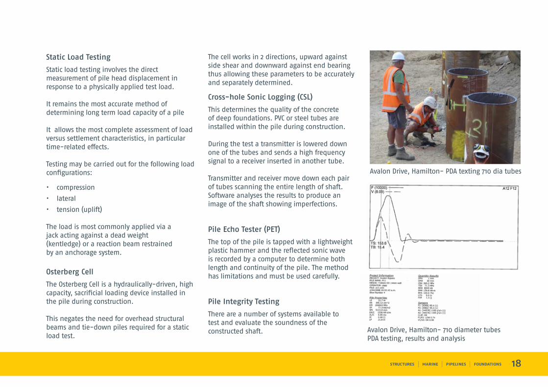
Cross-hole Sonic Logging (CSL)
This determines the quality of the concrete of deep foundations. PVC or steel tubes are installed within the pile during construction.
During the test a transmitter is lowered down one of the tubes and sends a high frequency signal to a receiver inserted in another tube.
Transmitter and receiver move down each pair of tubes scanning the entire length of shaft. Software analyses the results to produce an image of the shaft showing imperfections.
Pile Echo Tester (PET)
The top of the pile is tapped with a lightweight plastic hammer and the reflected sonic wave is recorded by a computer to determine both length and continuity of the pile. The method has limitations and must be used carefully.
Pile Integrity Testing
There are a number of systems available to test and evaluate the soundness of the constructed shaft.
Avalon Drive, Hamilton- PDA texting 710 dia tubes
GBC Project Eastport- CFA Pile Static load test result
Tauranga Harbour Link- 11mn static load test
Avalon Drive, Hamilton- 710 diameter tubesPDA testing, results and analysis
1
Brian Perry Civil’s ground improvement techniques allow a variety of structures to be supported without the use of traditional pile foundations.
These techniques can be used to:
• Control settlement
• Reduce lateral earth pressures
• Increase ground bearing capacity
• Avoid liquefaction
• Accelerate consolidation
• Improve slope stability
Brian Perry Civil has experience in techniques including:
• Vibrocompaction (wet or dry)
• Vibroreplacement
• Dynamic compaction
• Vertical wick drains
• Lime cement columns
• Grouting
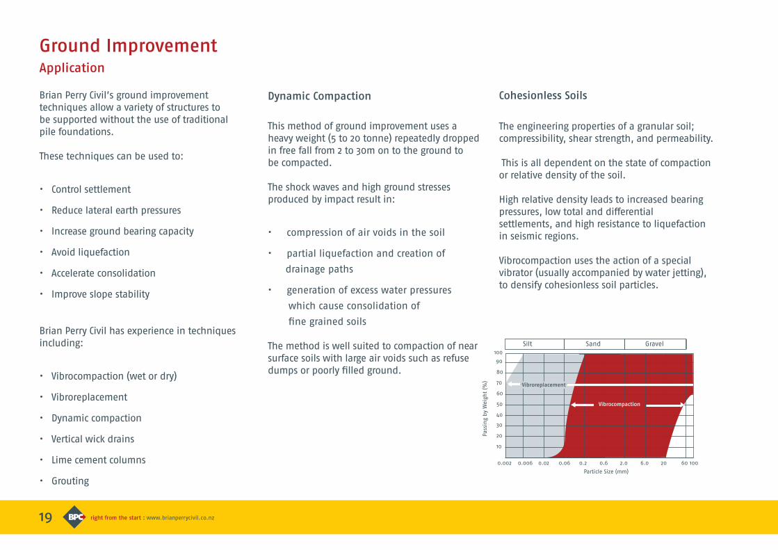
The engineering properties of a granular soil; compressibility, shear strength, and permeability.
This is all dependent on the state of compaction or relative density of the soil.
High relative density leads to increased bearing pressures, low total and differential settlements, and high resistance to liquefaction in seismic regions.
Vibrocompaction uses the action of a special vibrator (usually accompanied by water jetting), to densify cohesionless soil particles.
Ground ImprovementApplication
Cohesionless SoilsDynamic Compaction
This method of ground improvement uses a heavy weight (5 to 20 tonne) repeatedly dropped in free fall from 2 to 30m on to the ground to be compacted.
The shock waves and high ground stresses produced by impact result in:
• compression of air voids in the soil
• partial liquefaction and creation of
drainage paths
• generation of excess water pressures
which cause consolidation of
fine grained soils
The method is well suited to compaction of near surface soils with large air voids such as refuse dumps or poorly filled ground.
19
Silt
Particle Size (mm)
Pass
ing
by
Wei
ght
(%)
Sand Gravel
0.002 0.006 0.02 0.06 0.2 0.6 2.0 6.0 20 60 100
10
20
30
40
50
60
70
80
90
100
Vibroreplacement
Vibrocompaction
20
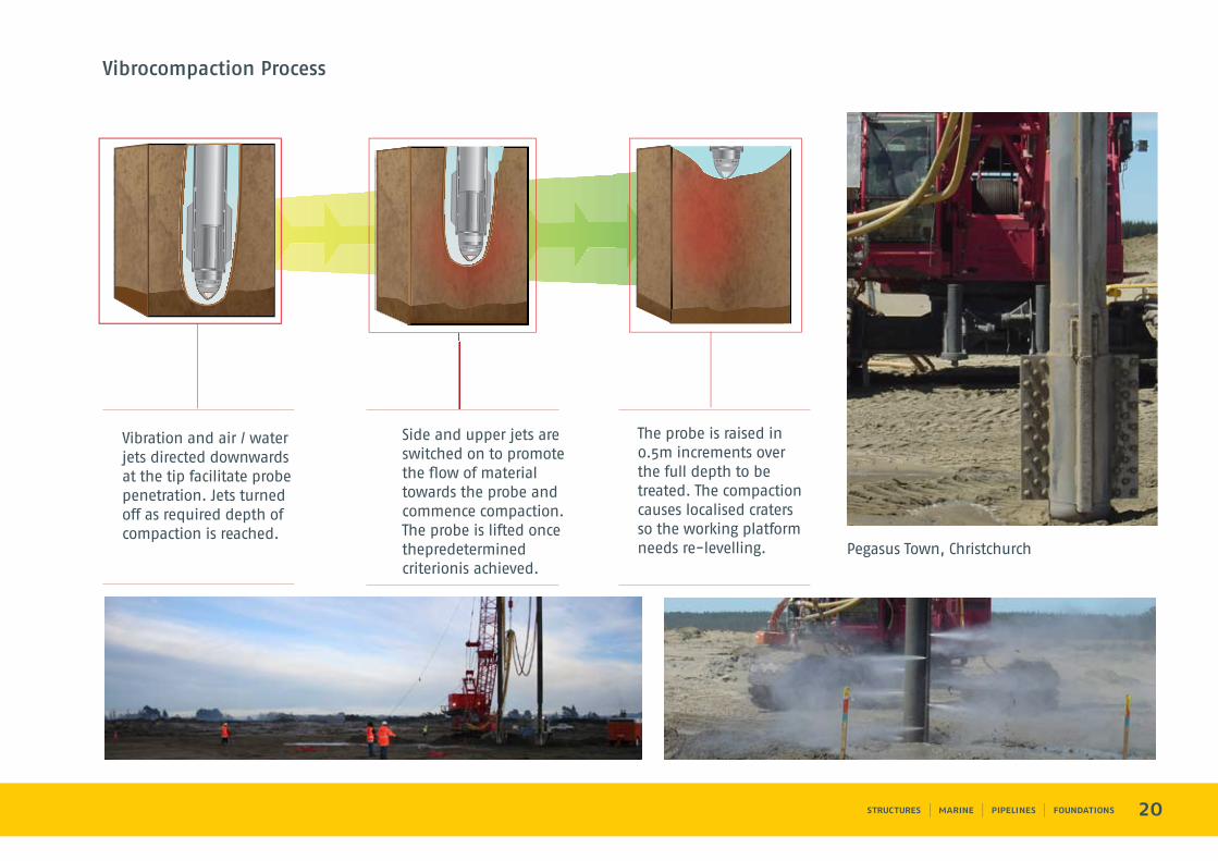
Vibrocompaction Process
Vibration and air / water jets directed downwards at the tip facilitate probe penetration. Jets turned off as required depth of compaction is reached.
Side and upper jets are switched on to promote the flow of material towards the probe and commence compaction. The probe is lifted once thepredetermined criterionis achieved.
The probe is raised in 0.5m increments over the full depth to be treated. The compaction causes localised craters so the working platform needs re-levelling. Pegasus Town, Christchurch
21
Cohesive to Cohesionless Soils
Vibroreplacement / Stone Columns (wet or dry)
In this process soil improvement of sensitive soft clays, sands and silts is achieved by reinforcing weak soils with densely compacted granular columns.
A vibrator is used to penetrate and displace the soil and to compact a dense column of clean, inert stone.
This is introduced in stages during the compaction process.
Jetting water is often used to assist the penetration of the vibro head.
The surrounding soil confines the granular columns and allows the columns to develop a higher bearing pressure, this is relative to the surrounding ground.
The stone columns and the surrounding soils form an integrated system with low compressibility and improved bearing capacity.
Cohesive Soils
Dewatering using Wick Drains
Wick drains are used to improve the rate of consolidation of low permeability soils by reducing the length of drainage paths within the soil.
Prefabricated wicks are inserted vertically into the ground by a purpose-built rig. Pattern and depth are determined by the consolidation properties of the soil and the desired time for consolidation to occur.
Soil Mixing
Soft clays and silts can be stabilised by mixing the clay with unslaked lime or other cement materials. The resulting stabilised soil has the consistency of stiff to hard clay with lower compressibility and higher permeability than the unstabilised soil.
The net effect is a reduction in total and differential settlements under structural loads and an increase in the rate of this settlement because the increased permeability allows the columns to act as drains and dissipate pore water pressures.
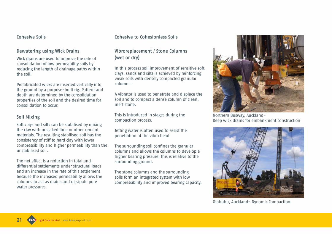
Northern Busway, Auckland-Deep wick drains for embankment construction
Otahuhu, Auckland- Dynamic Compaction
22
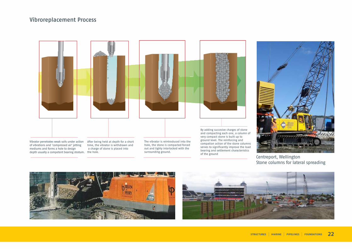
Vibroreplacement Process
After being held at depth for a short time, the vibrator is withdrawn and a charge of stone is placed intothe hole.
The vibrator is reintroduced into the hole, the stone is compacted forced out and tighly interlocked with the surrounding ground.
By adding succesive charges of stone and compacting each one, a column of very compact stone is built up to ground level. The reinforcing and compation action of the stone columns serves to significantly improve the load bearing and settlement characteristics of the ground
Vibrator penetrates weak soils under actionof vibrations and ‘compressed air’ jettingmediums and forms a hole to design depth usually a competent bearing stratum.
Northern Busway, Auckland-Deep wick drains for embankment construction
Otahuhu, Auckland- Dynamic Compaction
Centreport, WellingtonStone columns for lateral spreading
23
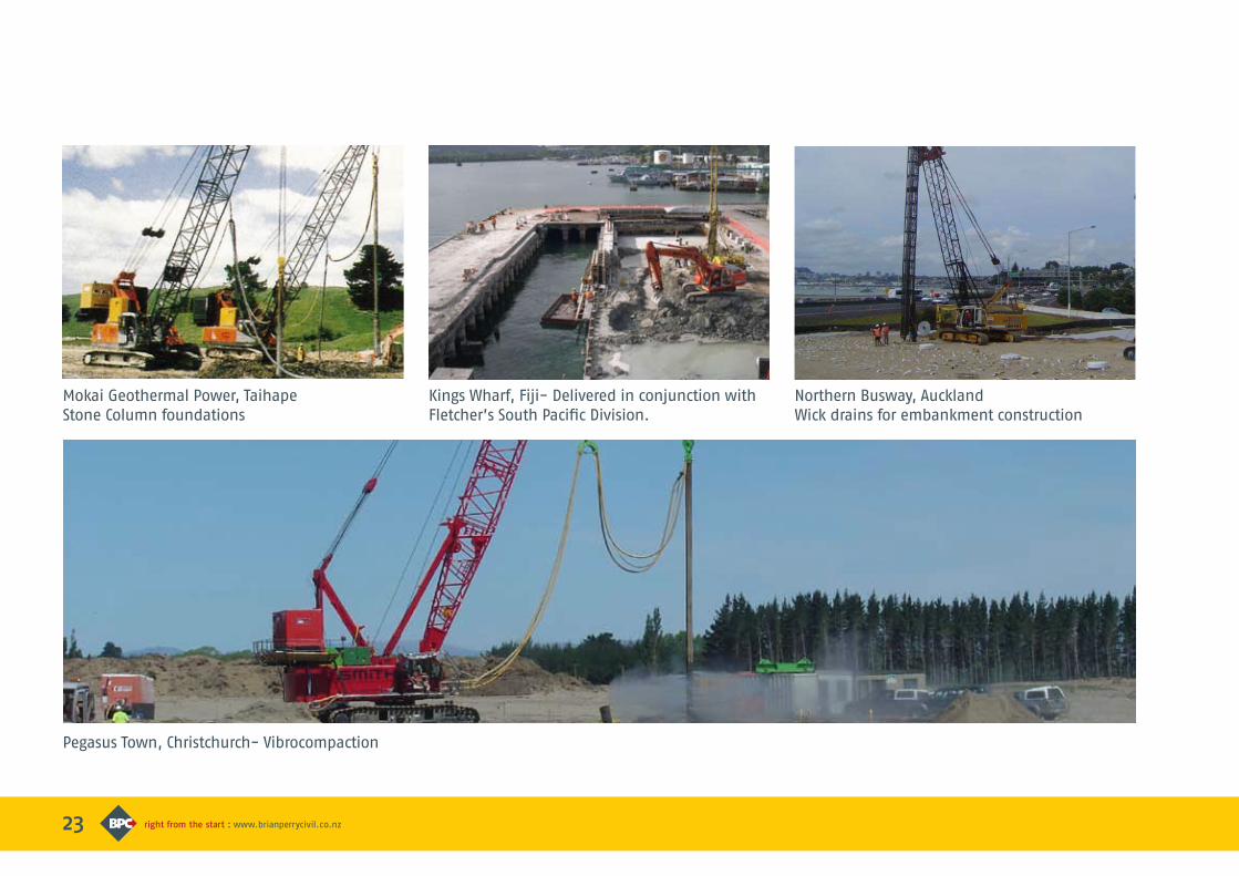
Mokai Geothermal Power, TaihapeStone Column foundations
Pegasus Town, Christchurch- Vibrocompaction
Kings Wharf, Fiji- Delivered in conjunction with Fletcher’s South Pacific Division.
Northern Busway, AucklandWick drains for embankment construction
24
Kings Wharf, Fiji- Delivered in conjunction with Fletcher’s South Pacific Division.
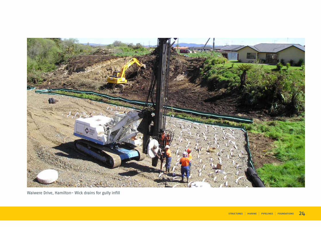
Waiwere Drive, Hamilton- Wick drains for gully infill
25
Pressure grouting is a widely used technique to:
• Seal cavities in retaining and cut-off walls
• Increase ground resistance in anchor and
tie-back systems
• Improve pile performance
Pressure GroutingApplication
Instrumented Grouting Plant
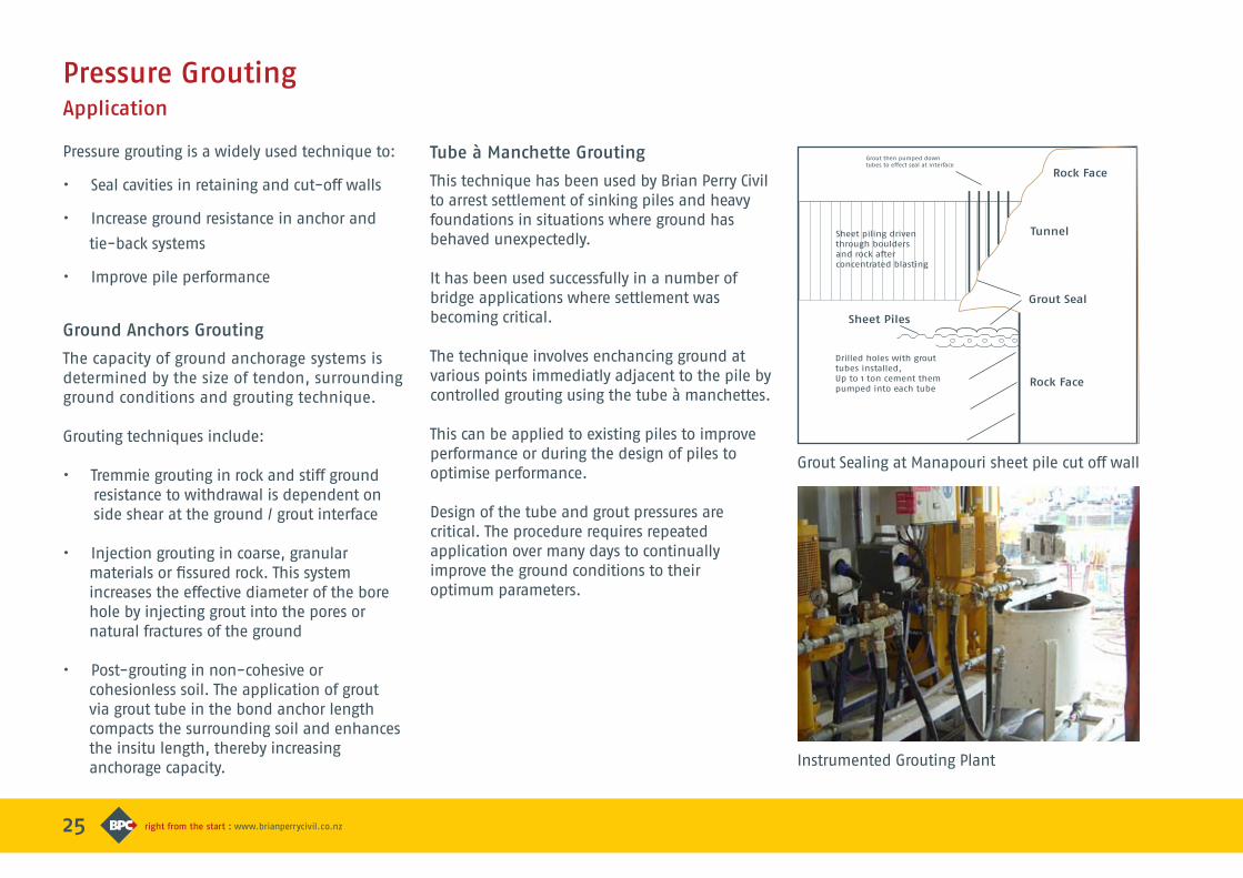
Grout Sealing at Manapouri sheet pile cut off wall
Ground Anchors Grouting
The capacity of ground anchorage systems is determined by the size of tendon, surrounding ground conditions and grouting technique.
Grouting techniques include:
• Tremmie grouting in rock and stiff ground resistance to withdrawal is dependent on side shear at the ground / grout interface
• Injection grouting in coarse, granular materials or fissured rock. This system increases the effective diameter of the bore hole by injecting grout into the pores or natural fractures of the ground
• Post-grouting in non-cohesive or cohesionless soil. The application of grout via grout tube in the bond anchor length compacts the surrounding soil and enhances the insitu length, thereby increasing anchorage capacity.
Tube à Manchette Grouting
This technique has been used by Brian Perry Civil to arrest settlement of sinking piles and heavy foundations in situations where ground has behaved unexpectedly.
It has been used successfully in a number of bridge applications where settlement was becoming critical.
The technique involves enchancing ground at various points immediatly adjacent to the pile by controlled grouting using the tube à manchettes.
This can be applied to existing piles to improve performance or during the design of piles to optimise performance.
Design of the tube and grout pressures are critical. The procedure requires repeated application over many days to continually improve the ground conditions to their optimum parameters.
Grout then pumped downtubes to effect seal at interface
Sheet piling driven through boulders and rock after concentrated blasting
Drilled holes with grout tubes installed,Up to 1 ton cement them
pumped into each tubeRock Face
Rock Face
Tunnel
Grout Seal
Sheet Piles
226
Instrumented Grouting Plant
Grout Sealing at Manapouri sheet pile cut off wall
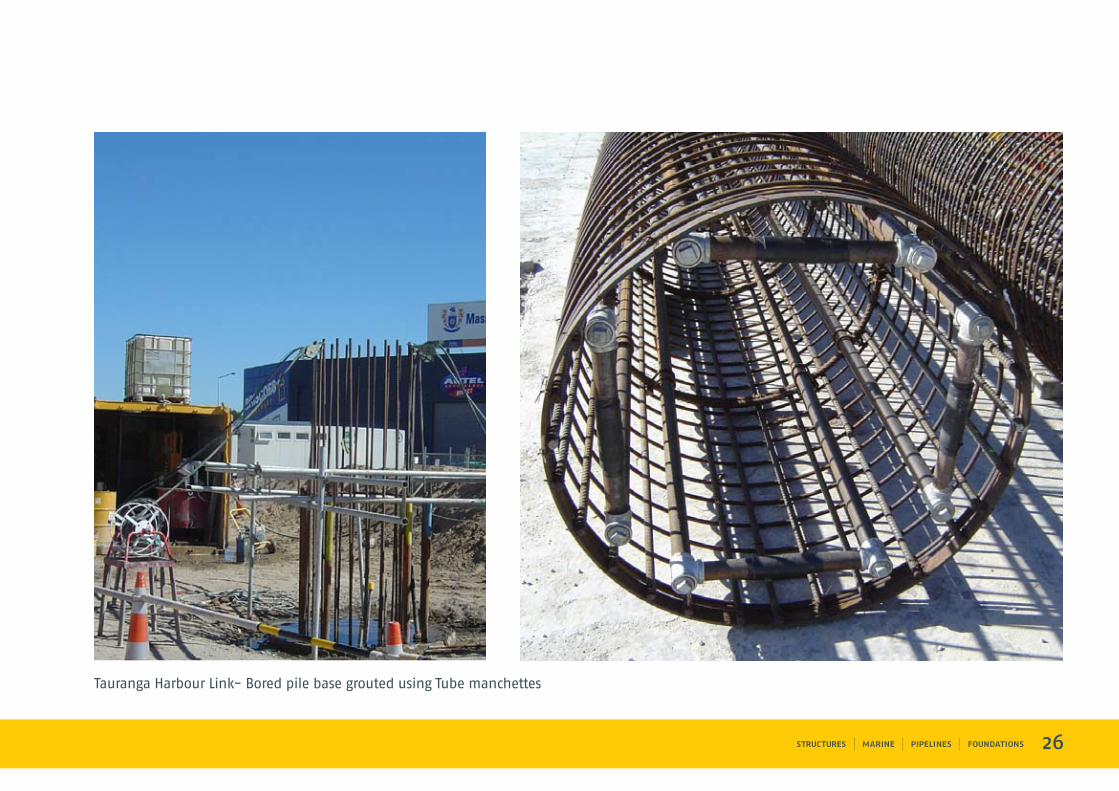
Tauranga Harbour Link- Bored pile base grouted using Tube manchettes
27
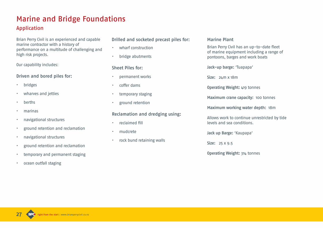
Brian Perry Civil is an experienced and capable marine contractor with a history of performance on a multitude of challenging and high risk projects.
Our capability includes:
Driven and bored piles for:
• bridges
• wharves and jetties
• berths
• marinas
• navigational structures
• ground retention and reclamation
• navigational structures
• ground retention and reclamation
• temporary and permanent staging
• ocean outfall staging
• wharf construction
• bridge abutments
Sheet Piles for:
• permanent works
• coffer dams
• temporary staging
• ground retention
Reclamation and dredging using:
• reclaimed fill
• mudcrete
• rock bund retaining walls
Marine and Bridge FoundationsApplication
Marine Plant
Brian Perry Civil has an up-to-date fleet of marine equipment including a range of pontoons, barges and work boats
Jack-up barge: ‘Tuapapa’
Size: 24m x 18m
Operating Weight: 419 tonnes
Maximum crane capacity: 100 tonnes
Maximum working water depth: 18m
Allows work to continue unrestricted by tide levels and sea conditions.
Jack up Barge: ‘Kaupapa’
Size: 25 x 9.5
Operating Weight: 314 tonnes
Drilled and socketed precast piles for:
28
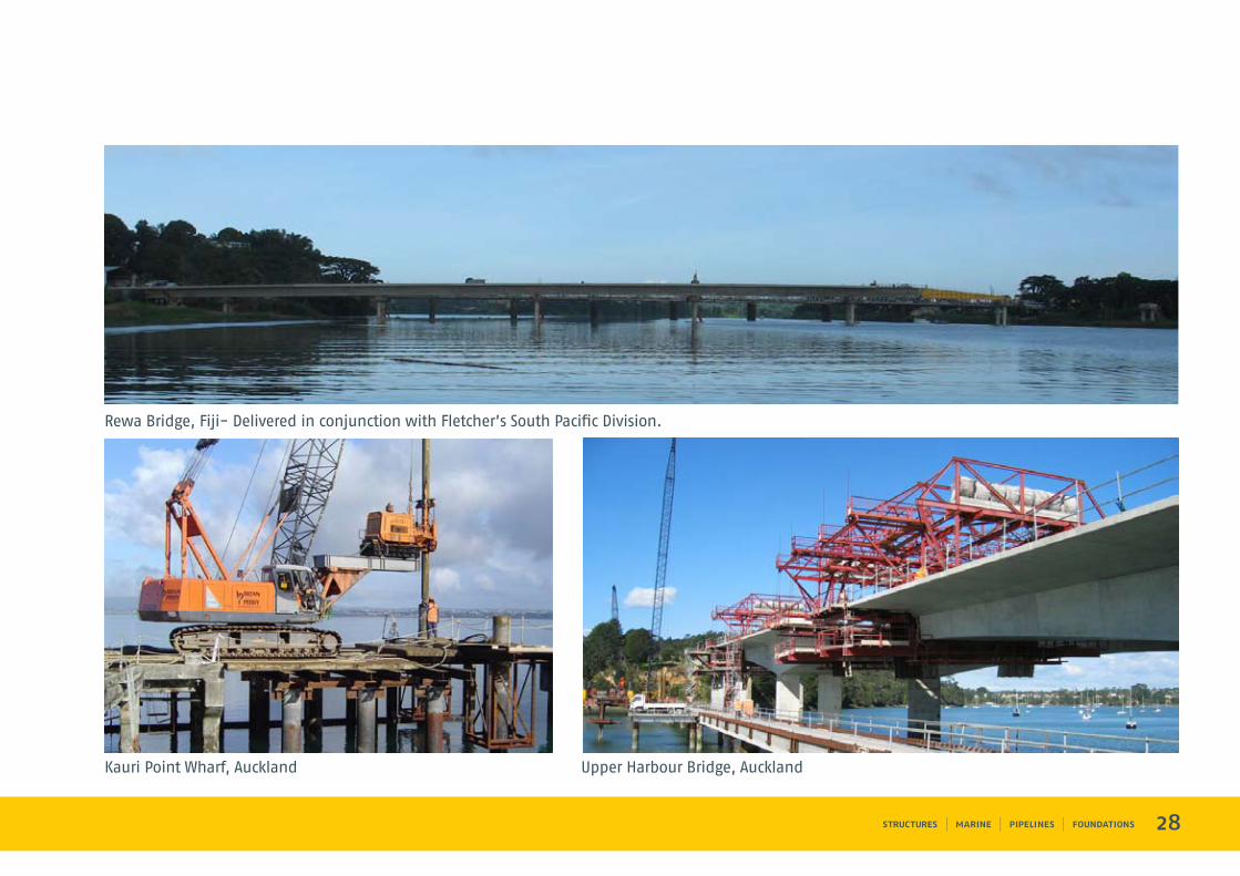
Rewa Bridge, Fiji- Delivered in conjunction with Fletcher’s South Pacific Division.
Kauri Point Wharf, Auckland Upper Harbour Bridge, Auckland
29
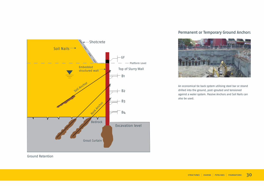
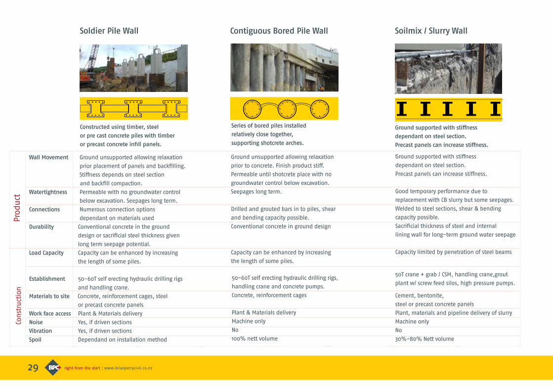
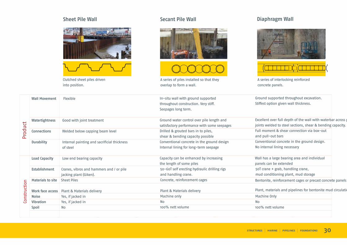
Brian Perry Civil offers a selection of retaining walls for a wide range of applications.
The wall type selected depends on the ground conditions, the standard of finish and the level of water tightness required.
Retaining wall methods include:
• Soldier piles in timber, steel or
precast concrete
• Contiguous bored pile wall with
shotcrete arch
• Secant pile walls
• Sheet pile walls
• Permanent or temporary ground anchors
• Diaphragm walls
• Gravity walls –
crib / gabion / reinforced earth
• Slurry walls
Ground RetentionApplication
Soho Square, Auckland
30
An economical tie back system utilising steel bar or strand
drilled into the ground, post-grouted and tensioned
against a waler system. Passive Anchors and Soil Nails can
also be used.
Permanent or Temporary Ground Anchors
Ground Retention
GF
Top of Slurry Wall
Bedrock
Grout Curtain
ASo
il nch
or
Rock
Anch
or
B1
B2
B3
B4
Platform Level
Shotcrete
Soil Nails
Embedded structured wall
Excavation level
29
Wall Movement Ground unsupported allowing relaxation
prior placement of panels and backfilling.
Stiffness depends on steel section
and backfill compaction.
Watertightness Permeable with no groundwater control
below excavation. Seepages long term.
Connections Numerous connection options
dependant on materials used
Durability Conventional concrete in the ground
design or sacrificial steel thickness given
long term seepage potential.
Load Capacity Capacity can be enhanced by increasing
the length of some piles.
Establishment 50-60T self erecting hydraulic drilling rigs
and handling crane.
Materials to site Concrete, reinforcement cages, steel
or precast concrete panels
Work face access Plant & Materials delivery
Noise Yes, if driven sections
Vibration Yes, if driven sections
Spoil Dependand on installation method
Constructed using timber, steel
or pre cast concrete piles with timber
or precast concrete infill panels.
Soldier Pile Wall
Ground unsupported allowing relaxation
prior to concrete. Finish product stiff.
Permeable until shotcrete place with no
groundwater control below excavation.
Seepages long term.
Drilled and grouted bars in to piles, shear
and bending capacity possible.
Conventional concrete in ground design
Capacity can be enhanced by increasing
the length of some piles.
Contiguous Bored Pile Wall
Series of bored piles installed
relatively close together,
supporting shotcrete arches.
Ground supported with stiffness
dependant on steel section.
Precast panels can increase stiffness.
Good temporary performance due to
replacement with CB slurry but some seepages.
Welded to steel sections, shear & bending
capacity possible.
Sacrificial thickness of steel and internal
lining wall for long-term ground water seepage
Capacity limited by penetration of steel beams
Ground supported with stiffness
dependant on steel section.
Precast panels can increase stiffness.
.
Soilmix / Slurry Wall
Con
stru
ctio
nPr
oduct
50T crane + grab / CSM, handling crane,grout
plant w/ screw feed silos, high pressure pumps.
Cement, bentonite,
steel or precast concrete panels
Plant, materials and pipeline delivery of slurry
Machine only
No
30%-80% Nett volume
50-60T self erecting hydraulic drilling rigs,
handling crane and concrete pumps.
Concrete, reinforcement cages
Plant & Materials delivery
Machine only
No
100% nett volume
30
Wall Movement Flexible
Watertightness Good with joint treatment
Connections Welded below capping beam level
Durability Internal painting and sacrificial thickness
of steel
Load Capacity Low end bearing capacity
Establishment Cranes, vibros and hammers and / or pile
jacking plant (Giken).
Materials to site Sheet Piles
Work face access Plant & Materials delivery
Noise Yes, if jacked in
Vibration Yes, if jacked in
Spoil No
A series of piles installed so that they
overlap to form a wall.
Secant Pile Wall
In-situ wall with ground supported
throughout construction. Very stiff.
Seepages long term.
Ground water control over pile length and
satisfactory performance with some seepages
Drilled & grouted bars in to piles,
shear & bending capacity possible
Conventional concrete in the ground design
Internal lining for long-term seepage
Capacity can be enhanced by increasing
the length of some piles
Diaphragm Wall
A series of interlocking reinforced
concrete panels.
Ground supported throughout excavation.
Stiffest option given wall thickness.
Excellent over full depth of the wall with waterbar across panel
joints welded to steel sections, shear & bending capacity.
Full moment & shear connection via box-out
and pull-out bars
Conventional concrete in the ground design.
No internal lining necessary
Sheet Pile Wall
Clutched sheet piles driven
into position.
Con
stru
ctio
nPr
oduct
50-60T self erecting hydraulic drilling rigs
and handling crane.
Concrete, reinforcement cages
Plant & Materials delivery
Machine only
No
100% nett volume
Plant, materials and pipelines for bentonite mud circulation
Bentonite, reinforcement cages or precast concrete panels
Machine Only
No
100% nett volume
Wall has a large bearing area and individual
panels can be extended
50T crane + grab, handling crane,
mud conditioning plant, mud storage

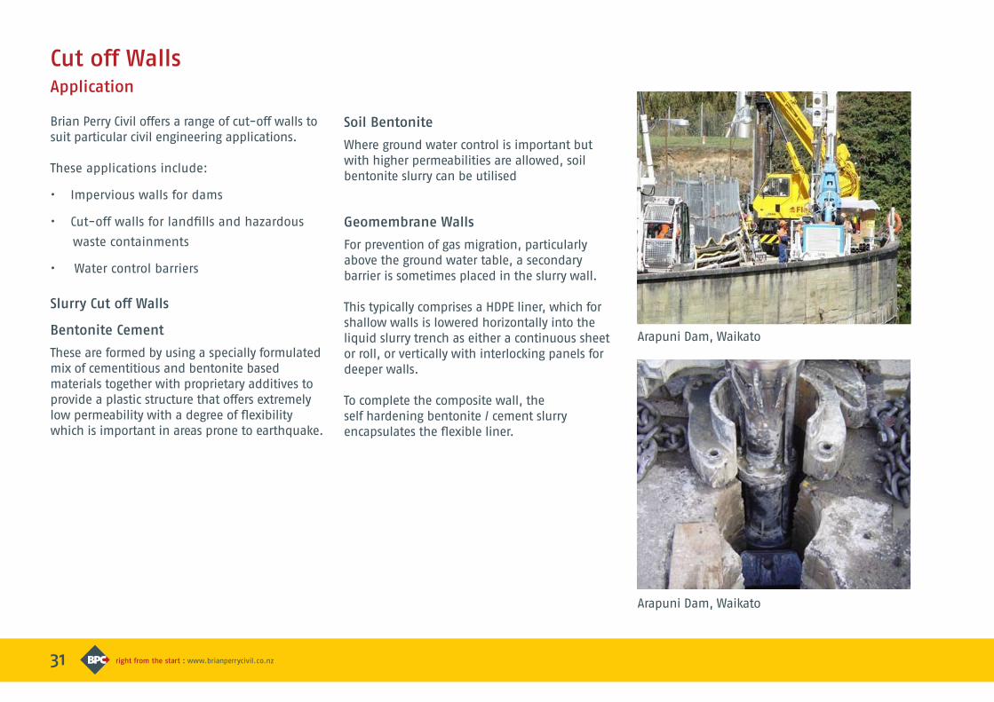
Arapuni Dam, Waikato
31
Brian Perry Civil offers a range of cut-off walls to suit particular civil engineering applications.
These applications include:
• Impervious walls for dams
• Cut-off walls for landfills and hazardous
waste containments
• Water control barriers
Slurry Cut off Walls
Bentonite Cement
These are formed by using a specially formulated mix of cementitious and bentonite based materials together with proprietary additives to provide a plastic structure that offers extremely low permeability with a degree of flexibility which is important in areas prone to earthquake.
Cut off WallsApplication
Soil Bentonite
Where ground water control is important but with higher permeabilities are allowed, soil bentonite slurry can be utilised
Geomembrane Walls
For prevention of gas migration, particularly above the ground water table, a secondary barrier is sometimes placed in the slurry wall.
This typically comprises a HDPE liner, which for shallow walls is lowered horizontally into the liquid slurry trench as either a continuous sheet or roll, or vertically with interlocking panels for deeper walls.
To complete the composite wall, the self hardening bentonite / cement slurry encapsulates the flexible liner.
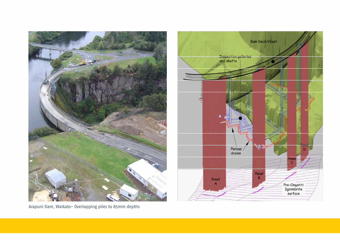
232
Arapuni Dam, Waikato- Overlapping piles to 85mm depthsArapuni Dam, Waikato
33
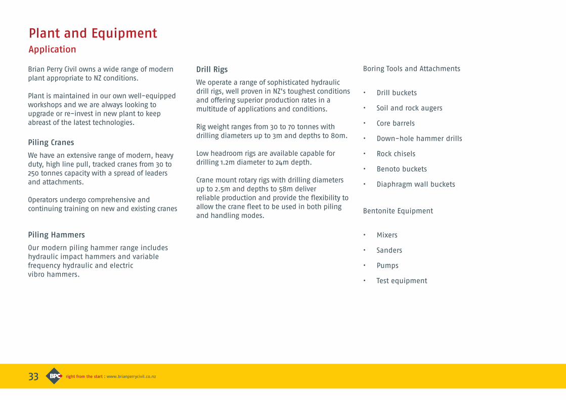
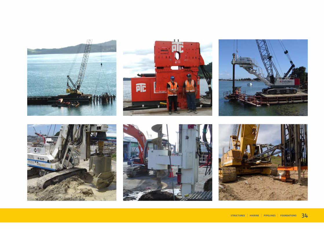
Brian Perry Civil owns a wide range of modern plant appropriate to NZ conditions.
Plant is maintained in our own well-equipped workshops and we are always looking to upgrade or re-invest in new plant to keep abreast of the latest technologies.
Piling Cranes
We have an extensive range of modern, heavy duty, high line pull, tracked cranes from 30 to 250 tonnes capacity with a spread of leaders and attachments.
Operators undergo comprehensive and continuing training on new and existing cranes
Piling Hammers
Our modern piling hammer range includes hydraulic impact hammers and variable frequency hydraulic and electric vibro hammers.
Plant and EquipmentApplication
Drill Rigs
We operate a range of sophisticated hydraulic drill rigs, well proven in NZ’s toughest conditions and offering superior production rates in a multitude of applications and conditions.
Rig weight ranges from 30 to 70 tonnes with drilling diameters up to 3m and depths to 80m.
Low headroom rigs are available capable for drilling 1.2m diameter to 24m depth.
Crane mount rotary rigs with drilling diameters up to 2.5m and depths to 58m deliver reliable production and provide the flexibility to allow the crane fleet to be used in both pilingand handling modes.
Boring Tools and Attachments
• Drill buckets
• Soil and rock augers
• Core barrels
• Down-hole hammer drills
• Rock chisels
• Benoto buckets
• Diaphragm wall buckets
Bentonite Equipment
• Mixers
• Sanders
• Pumps
• Test equipment
34
31
Brian Perry Civil offers a range of cut-off walls to suit particular civil engineering applications.
These applications include:
• Impervious walls for dams
• Cut-off walls for landfills and hazardous
waste containments
• Water control barriers
Slurry Cut off Walls
Bentonite Cement
These are formed by using a specially formulated mix of cementitious and bentonite based materials together with proprietary additives to provide a plastic structure that offers extremely low permeability with a degree of flexibility which is important in areas prone to earthquake.
Cut off WallsApplication
Soil Bentonite
Where ground water control is important but with higher permeabilities are allowed, soil bentonite slurry can be utilised
Geomembrane Walls
For prevention of gas migration, particularly above the ground water table, a secondary barrier is sometimes placed in the slurry wall.
This typically comprises a HDPE liner, which for shallow walls is lowered horizontally into the liquid slurry trench as either a continuous sheet or roll, or vertically with interlocking panels for deeper walls.
To complete the composite wall, the self hardening bentonite / cement slurry encapsulates the flexible liner.
Arapuni Dam, Waikato
Arapuni Dam, Waikato

232
Arapuni Dam, Waikato- Overlapping piles to 85mm depths
Arapuni Dam, Waikato
Arapuni Dam, Waikato