catalog & specification guide holland...
TRANSCRIPT
XL-FW10066SG-en-US Rev C
CATALOG & SPECIFICATION GUIDE
HOLLAND FIFTH WHEELS
OFFERING RANGE OF FIFTH WHEEL MODELS TO MEET YOUR APPLICATION NEEDS
2012
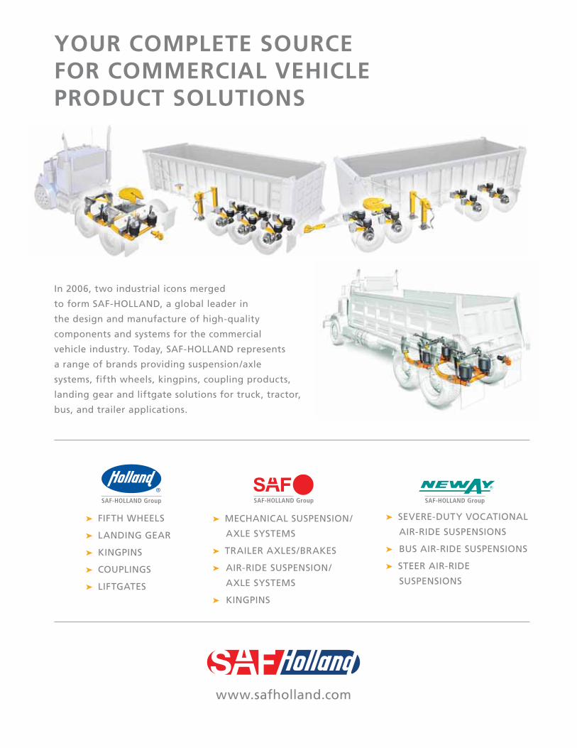
In 2006, two industrial icons merged
to form SAF-HOLLAND, a global leader in
the design and manufacture of high-quality
components and systems for the commercial
vehicle industry. Today, SAF-HOLLAND represents
a range of brands providing suspension/axle
systems, fifth wheels, kingpins, coupling products,
landing gear and liftgate solutions for truck, tractor,
bus, and trailer applications.
➤ FIFTH WHEELS
➤ LANDING GEAR
➤ KINGPINS
➤ COUPLINGS
➤ LIFTGATES
➤ MECHANICAL SUSPENSION/
AXLE SYSTEMS
➤ TRAILER AXLES/BRAKES
➤ AIR-RIDE SUSPENSION/
AXLE SYSTEMS
➤ KINGPINS
➤ SEVERE-DUTY VOCATIONAL
AIR-RIDE SUSPENSIONS
➤ BUS AIR-RIDE SUSPENSIONS
➤ STEER AIR-RIDE
SUSPENSIONS
YOUR COMPLETE SOURCE FOR COMMERCIAL VEHICLE PRODUCT SOLUTIONS
www.safholland.com

Why Holland Fifth Wheels?
1
Holland has the Solution
Holland fifth wheels have earned a reputation of exceptional durability, reliability, and driver
productivity that continues to ˝raise the bar˝ on fifth wheel performance standards, while lowering
the total cost-of-ownership. The Holland fifth wheel product line is the most comprehensive in the
world, with designs for applications as varied as light commercial fifth wheels for small trailers and
recreational applications all the way to applications requiring up to 165,000 lbs. (74,844 kg.) of
vertical load capacity. As the fifth wheel industry’s technological leader, Holland fifth wheels have
been a part of virtually every fifth wheel innovation.® Mounting Base
®
® Fifth Wheel (world’s only completely lubrication free fifth wheel)
®
Whatever the demands of your application, Holland has the solution.
Guaranteed Performance
supplier accountability to the next level by offering the industry’s first ˝wear-out˝ (performance)
only provides the longest fifth wheel material and workmanship warranties in the industry, but
guarantees their durability as well.
leads the industry with proven value, high performance, and exceptional operating and economic
Can you afford not to spec Holland fifth wheels?
XL-FW10066SG-en-US Rev C 02-12 Amendments and errors reserved. © SAF-HOLLAND, Inc.

XL-FW10066SG-en-US Rev C 02-12 Amendments and errors reserved. © SAF-HOLLAND, Inc.
Table of Contents
2
FIFTH WHEEL CATALOG
Application Guide . . . . . . . . . . . . . . . . . . . . . . . . . . . . . . . . . . . . . . . . . . . . . . . . . . . . . . . .6
Options Overview . . . . . . . . . . . . . . . . . . . . . . . . . . . . . . . . . . . . . . . . . . . . . . . . . . . . . . . .9
Holland Fifth Wheel Top Plate Models
Standard FW35 . . . . . . . . . . . . . . . . . . . . . . . . . . . . . . . . . . . . . . . . . . . . . . . . . . . . . . . . . . . . . . . . . .12
® . . . . . . . . . . . . . . . . . . . . . . . . . . . . . . . . . . . . . . . . . . . . . . . . . . . . . . . . . . .13 FW17 . . . . . . . . . . . . . . . . . . . . . . . . . . . . . . . . . . . . . . . . . . . . . . . . . . . . . . . . . . . . . . . . . .14
. . . . . . . . . . . . . . . . . . . . . . . . . . . . . . . . . . . . . . . . . . . . . . . . . . . . . . . . . . .15 . . . . . . . . . . . . . . . . . . . . . . . . . . . . . . . . . . . . . . . . . . . . . . . . . . .16
. . . . . . . . . . . . . . . . . . . . . . . . . . . . . . . . . . . . . . . . . . . . . . . . . . . . . . . . . . . . . . . . . .17
Extra Capacity FW0070 . . . . . . . . . . . . . . . . . . . . . . . . . . . . . . . . . . . . . . . . . . . . . . . . . . . . . . . . . . . . . . . .18 FW0100/FW0165 . . . . . . . . . . . . . . . . . . . . . . . . . . . . . . . . . . . . . . . . . . . . . . . . . . . . . . . . .19
Extra Capacity/Fully Oscillating FW2080 . . . . . . . . . . . . . . . . . . . . . . . . . . . . . . . . . . . . . . . . . . . . . . . . . . . . . . . . . . . . . . . .20
Terminal Tractor FW35-03344. . . . . . . . . . . . . . . . . . . . . . . . . . . . . . . . . . . . . . . . . . . . . . . . . . . . . . . . . . . . .21 FW2870 . . . . . . . . . . . . . . . . . . . . . . . . . . . . . . . . . . . . . . . . . . . . . . . . . . . . . . . . . . . . . . . .22
Terminal Tractor/Fully Oscillating FW1560-C . . . . . . . . . . . . . . . . . . . . . . . . . . . . . . . . . . . . . . . . . . . . . . . . . . . . . . . . . . . . . .23
Terminal Tractor/Elevating FW2800/FW2900 . . . . . . . . . . . . . . . . . . . . . . . . . . . . . . . . . . . . . . . . . . . . . . . . . . . . . . . . .24
Light Commercial FW6000 . . . . . . . . . . . . . . . . . . . . . . . . . . . . . . . . . . . . . . . . . . . . . . . . . . . . . . . . . . . . . . . .25 FW0001/FW0002 . . . . . . . . . . . . . . . . . . . . . . . . . . . . . . . . . . . . . . . . . . . . . . . . . . . . . . . . .26
Mounting Systems
Stationary Mounts (FW35, FW31, FW17, FW16, FWAL, FWS1) Foot Mount. . . . . . . . . . . . . . . . . . . . . . . . . . . . . . . . . . . . . . . . . . . . . . . . . . . . . . . . . . . . . .28
. . . . . . . . . . . . . . . . . . . . . . . . . . . . . . . . . . . . . . . . . . . . . . . . . . . . .29 Bracket for Angle Mounting . . . . . . . . . . . . . . . . . . . . . . . . . . . . . . . . . . . . . . . . . . . . . . . . .30 Bracket with Angle Mount . . . . . . . . . . . . . . . . . . . . . . . . . . . . . . . . . . . . . . . . . . . . . . . . . .31
Sliding Mounts (FW35, FW31, FW17, FW16, FWAL, FWS1) . . . . . . . . . . . . . . . . . . . . . . . . . . . . . . . . . . . . . . . . . . . . . . . . . . . . . . .32
. . . . . . . . . . . . . . . . . . . . . . . . . . . . . . . . . . . . . . . . . . .33

Table of Contents
3
Mounting Systems continued
FW0070 Series Stationary Mounts Foot Mount. . . . . . . . . . . . . . . . . . . . . . . . . . . . . . . . . . . . . . . . . . . . . . . . . . . . . . . . . . . . . .34
. . . . . . . . . . . . . . . . . . . . . . . . . . . . . . . . . . . . . . . . . . . . . . . . . . . . .34 Bracket for Angle Mounting . . . . . . . . . . . . . . . . . . . . . . . . . . . . . . . . . . . . . . . . . . . . . . . . .35 Bracket with Angle Mount . . . . . . . . . . . . . . . . . . . . . . . . . . . . . . . . . . . . . . . . . . . . . . . . . .35
FW0070 Series Sliding Mounts. . . . . . . . . . . . . . . . . . . . . . . . . . . . . . . . . . . .36
No-Tilt Stationary Mounts (FW35). . . . . . . . . . . . . . . . . . . . . . . . . . . . . . . . . . . . . . . . . . . . . . . . . . . . . . . . . .37
. . . . . . . . . . . . . . . . . . . . . . . . . . . . . . . . . . . .38
No-Tilt Sliding Mounts (FW35). . . . . . . . . . . . . . . . . . . . . . . . . . . . . . . . . . . . . . . . . . . . . . . . . . . . . . . . . .39
. . . . . . . . . . . . . . . . . . . . . . . . . . . . . . . . . . . .40
Kompensator® Stationary Mounts (FW35 and FW0070) . . . . . . . . . . . . . . . . . . . . . . . . . . . . . . . . . . . . . . . . . . . . . . . . . . . . .41
. . . . . . . . . . . . . . . . . . . . . . . . . .42. . . . . . . . . . . . . . . . . . . . . . . . . . . . . . . . . . . .43
. . . . . . . . . . . . . . . . . . . . . . . . . . . . . . . . . . . . .44
Kompensator® Sliding Mounts (FW35 and FW0070). . . . . . . . . . . . . . . . . . . . . . . . . . . . . . . . . . . .45
Custom Service Tools for Fifth Wheels . . . . . . . . . . . . . . . . . . . . . . . . . . . . . . . . . .46
SPECIFICATION GUIDESpecification Steps . . . . . . . . . . . . . . . . . . . . . . . . . . . . . . . . . . . . . . . . . . . . . . . . . . . . . . .48
Items to Consider . . . . . . . . . . . . . . . . . . . . . . . . . . . . . . . . . . . . . . . . . . . . . . . . . . . . . . . .49
Assembly Part Numbers and Dimensions FW35 . . . . . . . . . . . . . . . . . . . . . . . . . . . . . . . . . . . . . . . . . . . . . . . . . . . . . . . . . . . . . . . . . . . .56 FW31 . . . . . . . . . . . . . . . . . . . . . . . . . . . . . . . . . . . . . . . . . . . . . . . . . . . . . . . . . . . . . . . . . . . .64 FW17 . . . . . . . . . . . . . . . . . . . . . . . . . . . . . . . . . . . . . . . . . . . . . . . . . . . . . . . . . . . . . . . . . . . .67 FW16 . . . . . . . . . . . . . . . . . . . . . . . . . . . . . . . . . . . . . . . . . . . . . . . . . . . . . . . . . . . . . . . . . . . .70
. . . . . . . . . . . . . . . . . . . . . . . . . . . . . . . . . . . . . . . . . . . . . . . . . . . . . . . . . . . . . . . . . . . .73
. . . . . . . . . . . . . . . . . . . . . . . . . . . . . . . . . . . . . . . . . . . . . . . . . . . . . . . . . . . . . . . . . . . .76 FW0070 . . . . . . . . . . . . . . . . . . . . . . . . . . . . . . . . . . . . . . . . . . . . . . . . . . . . . . . . . . . . . . . . . .79 FW0100 . . . . . . . . . . . . . . . . . . . . . . . . . . . . . . . . . . . . . . . . . . . . . . . . . . . . . . . . . . . . . . . . . .83 FW0165 . . . . . . . . . . . . . . . . . . . . . . . . . . . . . . . . . . . . . . . . . . . . . . . . . . . . . . . . . . . . . . . . . .83 FW2080 . . . . . . . . . . . . . . . . . . . . . . . . . . . . . . . . . . . . . . . . . . . . . . . . . . . . . . . . . . . . . . . . . .84
Glossary . . . . . . . . . . . . . . . . . . . . . . . . . . . . . . . . . . . . . . . . . . . . . . . . . . . . . . . . . . . . . . . . . .86
XL-FW10066SG-en-US Rev C 02-12 Amendments and errors reserved. © SAF-HOLLAND, Inc.

4
THIS PAGE INTENTIONALLY LEFT BLANK
XL-FW10066SG-en-US Rev C 02-12 Amendments and errors reserved. © SAF-HOLLAND, Inc.

APPLICATION GUIDE
OPTIONS OVERVIEW

Standard Duty LowLube NoLube Alum. NoLubeTop Plate 17 (XA-17) 16 (XA-161) S1 (XA-S1) 35 (XA-351) 31 (XA-311) AL (XA-AL)
22,700 kg. 22,700 kg. 22,700 kg. 25,000 kg. 25,000 kg. 25,000 kg.
68,000 kg. 68,000 kg. 68,000 kg. 68,000 kg. 68,000 kg. 68,000 kg.Mounting Style Stationary Sliding Stationary Sliding Stationary Sliding Stationary Sliding Stationary Sliding Stationary Sliding
TractorsVan Trailers
(3)(4)
(5) (5)
(3)(4) (3)(4)
B-Trains (3)(4) (3)(4)
Converter Dollies
XL-FW10066SG-en-US Rev C 02-12 Amendments and errors reserved. © SAF-HOLLAND, Inc.6
Application Guide
6
Standard Duty (1) Weight (GCW): .............................................
Gross Combination Weight (GCW)
Road Type: ....................................................
Trailer Type and Axle Limitation (2):
Note: Any tractor used for ˝short haul˝ (e.g. city pickup and delivery) is to be considered ˝Moderate Duty˝
Pivot Point Pivot Point
XL-FW10066SG-en-US Rev C 02-12 Amendments and errors reserved. © SAF-HOLLAND, Inc. 7
Application Guide
7
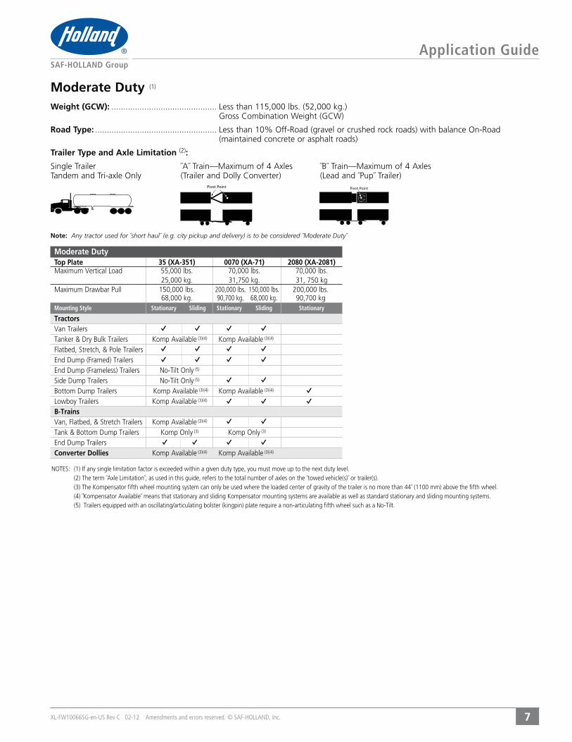
Moderate Duty (1)
Weight (GCW): ............................................. Gross Combination Weight (GCW)
Road Type: ....................................................(maintained concrete or asphalt roads)
Trailer Type and Axle Limitation (2):
Note: Any tractor used for ˝short haul˝ (e.g. city pickup and delivery) is to be considered ˝Moderate Duty˝
Pivot Point Pivot Point
Moderate DutyTop Plate 35 (XA-351) 0070 (XA-71) 2080 (XA-2081)
55,000 lbs. 70,000 lbs. 70,000 lbs. 25,000 kg. 31,750 kg. 31, 750 kg
200,000 lbs. 150,000 lbs. 200,000 lbs. 68,000 kg. 90,700 kg. 68,000 kg. 90,700 kgMounting Style Stationary Sliding Stationary Sliding Stationary
TractorsVan Trailers
(3)(4) (3)(4)
(5)
(5) (3)(4) (3)(4) (3)(4)
B-Trains (3)(4)
(3) (3)
Converter Dollies (3)(4) (3)(4)
XL-FW10066SG-en-US Rev C 02-12 Amendments and errors reserved. © SAF-HOLLAND, Inc.
Application Guide
88
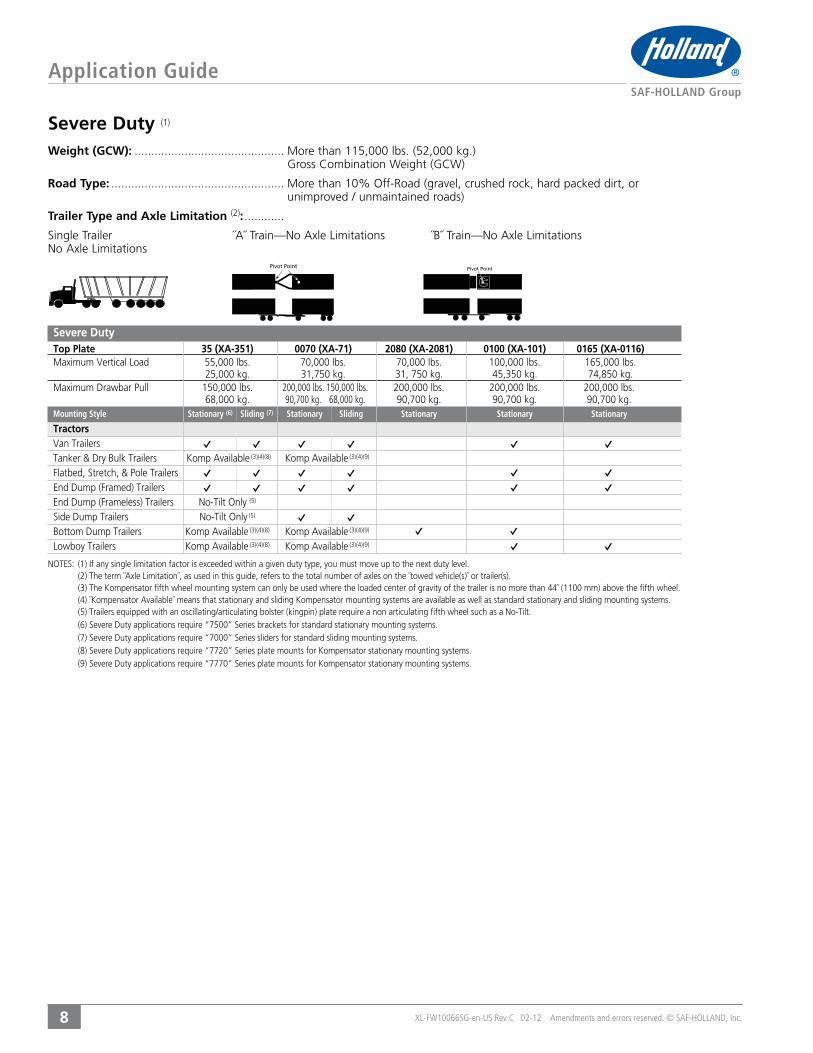
Severe Duty (1)
Weight (GCW): ............................................. More than 115,000 lbs. (52,000 kg.) Gross Combination Weight (GCW)
Road Type: ....................................................unimproved / unmaintained roads)
Trailer Type and Axle Limitation (2): ............
Severe DutyTop Plate 35 (XA-351) 0070 (XA-71) 2080 (XA-2081) 0100 (XA-101) 0165 (XA-0116)
100,000 lbs. 165,000 lbs. 25,000 kg. 31,750 kg. 31, 750 kg. 45,350 kg. 74,850 kg.
200,000 lbs. 150,000 lbs. 200,000 lbs. 200,000 lbs. 200,000 lbs. 68,000 kg. 90,700 kg. 68,000 kg. 90,700 kg. 90,700 kg. 90,700 kg.Mounting Style Stationary (6) Sliding (7) Stationary Sliding Stationary Stationary Stationary
TractorsVan Trailers
(3)(4)(8) (3)(4)(9)
(5) (5) (3)(4)(8) (3)(4)(9) (3)(4)(8) (3)(4)(9)
Pivot PointPivot Point
XL-FW10066SG-en-US Rev C 02-12 Amendments and errors reserved. © SAF-HOLLAND, Inc.
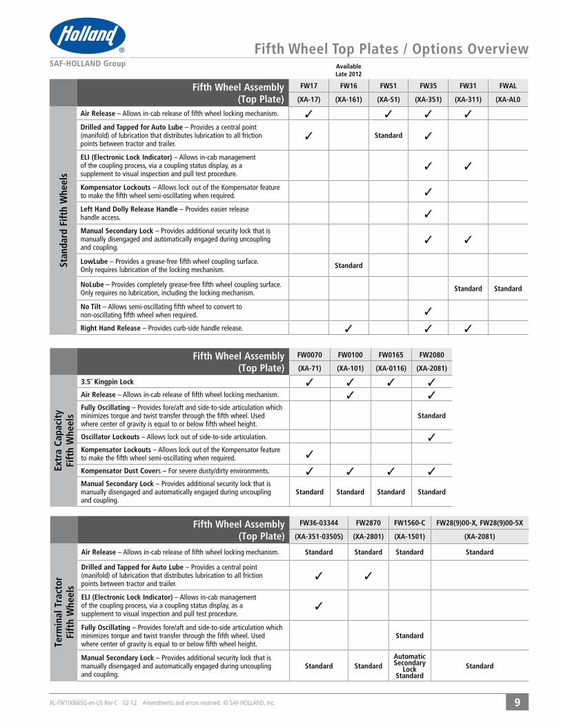
Fifth Wheel Top Plates / Options Overview
99
AvailableLate 2012
Fifth Wheel Assembly(Top Plate)
FW0070 FW0100 FW0165 FW2080
(XA-71) (XA-101) (XA-0116) (XA-2081)
Extr
a Ca
paci
tyFi
fth
Whe
els
3.5˝ Kingpin Lock ✓ ✓ ✓ ✓Air Release – Allows in-cab release of fifth wheel locking mechanism. ✓ ✓Fully Oscillating – Provides fore/aft and side-to-side articulation which minimizes torque and twist transfer through the fifth wheel. Used where center of gravity is equal to or below fifth wheel height.
Standard
Oscillator Lockouts – Allows lock out of side-to-side articulation. ✓Kompensator Lockouts – Allows lock out of the Kompensator feature to make the fifth wheel semi-oscillating when required. ✓
Kompensator Dust Covers – For severe dusty/dirty environments. ✓ ✓ ✓ ✓Manual Secondary Lock – Provides additional security lock that is manually disengaged and automatically engaged during uncoupling and coupling.
Standard Standard Standard Standard
Fifth Wheel Assembly(Top Plate)
FW36-03344 FW2870 FW1560-C FW28(9)00-X, FW28(9)00-5X
(XA-351-03505) (XA-2801) (XA-1501) (XA-2081)
Term
inal
Tra
ctor
Fift
h W
heel
s
Air Release – Allows in-cab release of fifth wheel locking mechanism. Standard Standard Standard Standard
Drilled and Tapped for Auto Lube – Provides a central point (manifold) of lubrication that distributes lubrication to all friction points between tractor and trailer.
✓ ✓
ELI (Electronic Lock Indicator) – Allows in-cab management of the coupling process, via a coupling status display, as a supplement to visual inspection and pull test procedure.
✓
Fully Oscillating – Provides fore/aft and side-to-side articulation which minimizes torque and twist transfer through the fifth wheel. Used where center of gravity is equal to or below fifth wheel height.
Standard
Manual Secondary Lock – Provides additional security lock that is manually disengaged and automatically engaged during uncoupling and coupling.
Standard StandardAutomaticSecondary
LockStandard
Standard
Fifth Wheel Assembly(Top Plate)
FW17 FW16 FWS1 FW35 FW31 FWAL
(XA-17) (XA-161) (XA-S1) (XA-351) (XA-311) (XA-AL0
Stan
dard
Fift
h W
heel
s
Air Release – Allows in-cab release of fifth wheel locking mechanism. ✓ ✓ ✓ ✓
Drilled and Tapped for Auto Lube – Provides a central point (manifold) of lubrication that distributes lubrication to all friction points between tractor and trailer.
✓ Standard ✓
ELI (Electronic Lock Indicator) – Allows in-cab management of the coupling process, via a coupling status display, as a supplement to visual inspection and pull test procedure.
✓ ✓
Kompensator Lockouts – Allows lock out of the Kompensator feature to make the fifth wheel semi-oscillating when required. ✓
Left Hand Dolly Release Handle – Provides easier release handle access. ✓
Manual Secondary Lock – Provides additional security lock that is manually disengaged and automatically engaged during uncoupling and coupling.
✓ ✓
LowLube – Provides a grease-free fifth wheel coupling surface. Only requires lubrication of the locking mechanism. Standard
NoLube – Provides completely grease-free fifth wheel coupling surface. Only requires no lubrication, including the locking mechanism. Standard Standard
No Tilt – Allows semi-oscillating fifth wheel to convert to non-oscillating fifth wheel when required. ✓
Right Hand Release – Provides curb-side handle release. ✓ ✓ ✓

XL-FW10066SG-en-US Rev C 02-12 Amendments and errors reserved. © SAF-HOLLAND, Inc.1010
THIS PAGE INTENTIONALLY LEFT BLANK
CONTENTS:
STANDARD, EXTRA CAPACITY, TERMINAL TRACTOR, AND LIGHT COMMERCIAL DUTY MODELS
CAPACITIES
APPLICATIONS
FEATURES
AVAILABLE OPTIONS
TOP PLATE PART NUMBERS
TOP PLATE WEIGHTS
AVAILABLE MOUNTING SYSTEMS
TOP PLATE DIMENSIONS
REBUILD AND REPLACEMENT KITS
FIFTH WHEEL
TOP PLATE
MODELS

XL-FW10066SG-en-US Rev C 02-12 Amendments and errors reserved. © SAF-HOLLAND, Inc.
Top Plate Models
12
Options Available
Warranty
Applications
FW35
Capacity
Features
Rebuild and Replacement Kits
Mounting Systems AvailableFor Complete Assembly Part Numbers refer to ˝Mounting System˝ pages.NOTE: Height and Travel data is given in INCHES
Dimensions24.2˝(614)
38.5˝(977)
13.5˝(343)
32.5˝(826)
19.0˝(483)
18.2˝(463)
40°Top Plate Part Numbers
DESCRIPTION PART NUMBER WEIGHT226 lbs.226 lbs.
For options, insert one of the following codes after the 6th digit.
Code 80Code 86
Code 24Code 02Code 28Code 06Code 06
DESCRIPTION RELEASE PART NUMBER
STATIONARY STYLES HEIGHTS
STANDARD BASESFoot Mount
6, 7, 8, 9
Brackets with Mounting Angles
NO TILT BASES8, 9
8
KOMPENSATOR BASES
10, 12, 13
9, 11, 12
SLIDING STYLES HEIGHTS TRAVELS
STANDARD BASES
7, 8, 912, 24,36, 48
NO TILT BASES
9, 1014, 20, 32,
44, 57
KOMPENSATOR BASES
1311, 17, 25,41, 54, 66
XL-FW10066SG-en-US Rev C 02-12 Amendments and errors reserved. © SAF-HOLLAND, Inc.
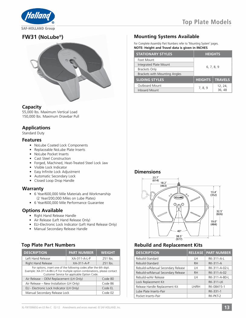
Top Plate Models
13
Rebuild and Replacement Kits
Dimensions
Mounting Systems Available
Options Available
Warranty
Features
Capacity
Applications
FW31 (NoLube®)
23.7˝(614)
38.5˝(977)
13.4˝(352)
32.5˝(826)
19.0˝(484)
18.2˝(463)
40°
DESCRIPTION PART NUMBER WEIGHT
251 lbs.
251 lbs.For options, insert one of the following codes after the 6th digit.
Code 80
Code 86
Code 02
Top Plate Part Numbers
DESCRIPTION RELEASE PART NUMBER
STATIONARY STYLES HEIGHTS
Foot Mount
6, 7, 8, 9
Brackets with Mounting Angles
SLIDING STYLES HEIGHTS TRAVELS
7, 8, 912, 24, 36, 48
For Complete Assembly Part Numbers refer to ˝Mounting System˝ pages.NOTE: Height and Travel data is given in INCHES

XL-FW10066SG-en-US Rev C 02-12 Amendments and errors reserved. © SAF-HOLLAND, Inc.
Top Plate Models
14
Rebuild and Replacement Kits
Dimensions
Mounting Systems AvailableFor Complete Assembly Part Numbers refer to ˝Mounting System˝ pages.NOTE: Height and Travel data is given in INCHES
24.5˝(622)
38.2˝(971)
10.6˝(269)
25.8˝(656)
15.2˝(386)
19.7˝(501)
40°
Features
Capacity
Warranty
Top Plate Part Number
Applications
FW17
Options Available
DESCRIPTION PART NUMBERDESCRIPTION PART NUMBER WEIGHT
202 lbs.For options, insert the following code after the 5th digit.
STATIONARY STYLES HEIGHTS
Foot Mount
6, 7, 8, 9
Brackets with Mounting Angles
SLIDING STYLES HEIGHTS TRAVELS
7, 8, 912, 24, 36, 48
XL-FW10066SG-en-US Rev C 02-12 Amendments and errors reserved. © SAF-HOLLAND, Inc.
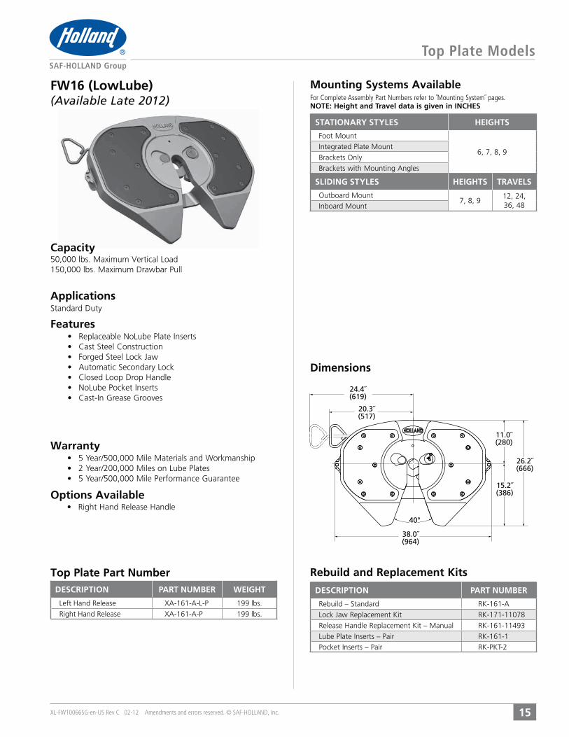
Top Plate Models
15
Rebuild and Replacement Kits
Dimensions
Mounting Systems AvailableFor Complete Assembly Part Numbers refer to ˝Mounting System˝ pages.NOTE: Height and Travel data is given in INCHES
24.4˝(619)
38.0˝(964)
11.0˝(280)
26.2˝(666)
15.2˝(386)
20.3˝(517)
40°
Features
Capacity
Warranty
Top Plate Part Number
Applications
FW16 (LowLube)(Available Late 2012)
Options Available
DESCRIPTION PART NUMBERDESCRIPTION PART NUMBER WEIGHT
199 lbs.
199 lbs.
STATIONARY STYLES HEIGHTS
Foot Mount
6, 7, 8, 9
Brackets with Mounting Angles
SLIDING STYLES HEIGHTS TRAVELS
7, 8, 912, 24, 36, 48
XL-FW10066SG-en-US Rev C 02-12 Amendments and errors reserved. © SAF-HOLLAND, Inc.
Top Plate Models
16
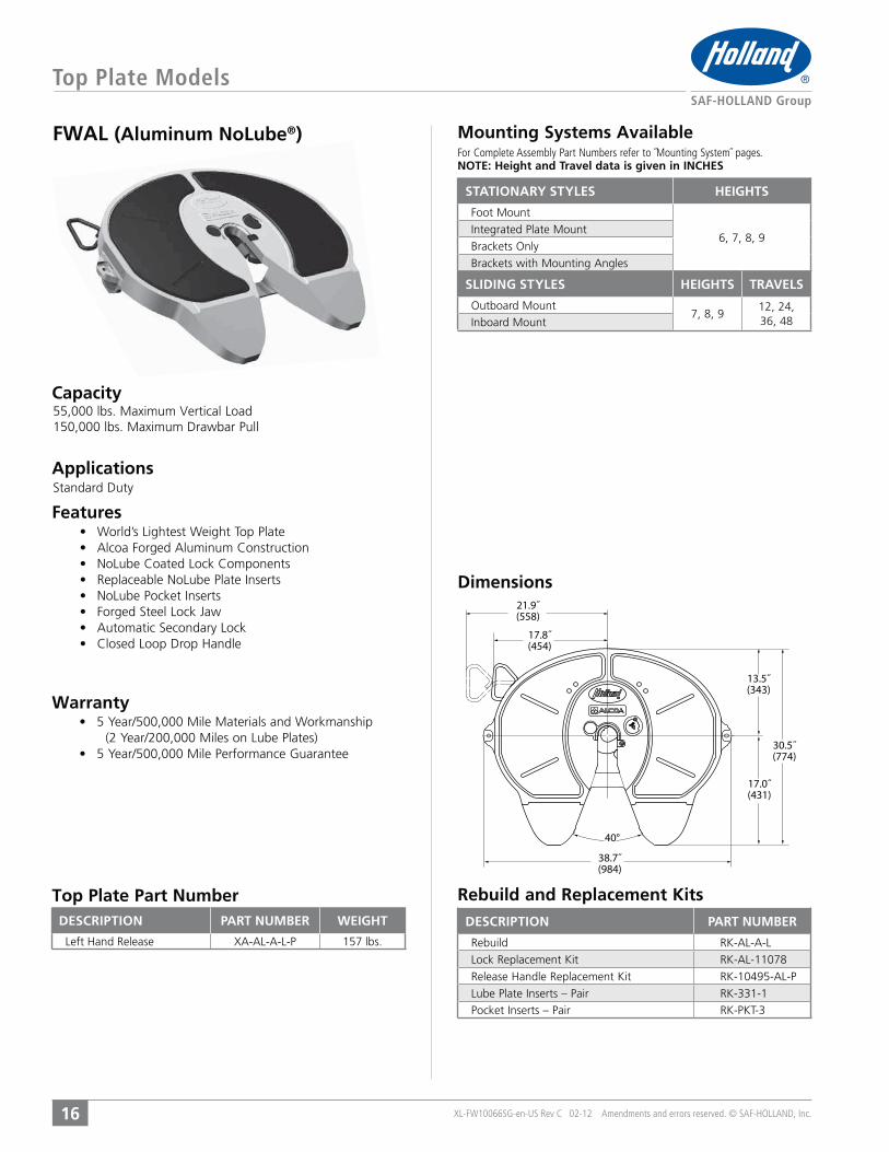
FWAL (Aluminum NoLube®)
Features
Applications
Capacity
Warranty
Top Plate Part Number Rebuild and Replacement Kits
Dimensions21.9˝(558)
38.7˝(984)
13.5˝(343)
30.5˝(774)
17.0˝(431)
17.8˝(454)
40°
Mounting Systems AvailableFor Complete Assembly Part Numbers refer to ˝Mounting System˝ pages.NOTE: Height and Travel data is given in INCHES
DESCRIPTION PART NUMBERDESCRIPTION PART NUMBER WEIGHT
157 lbs.
STATIONARY STYLES HEIGHTS
Foot Mount
6, 7, 8, 9
Brackets with Mounting Angles
SLIDING STYLES HEIGHTS TRAVELS
7, 8, 912, 24, 36, 48
XL-FW10066SG-en-US Rev C 02-12 Amendments and errors reserved. © SAF-HOLLAND, Inc.
Top Plate Models
17
Rebuild and Replacement KitsTop Plate Numbers
Dimensions
Mounting Systems AvailableFor Complete Assembly Part Numbers refer to ˝Mounting System˝ pages.NOTE: Height and Travel data is given in INCHES
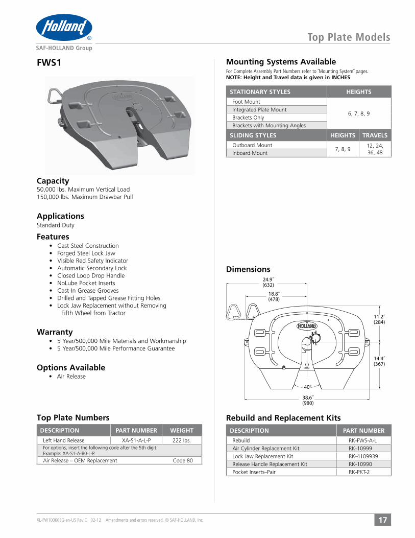
Options Available
Warranty
Features
Applications
Capacity
Fifth Wheel from Tractor
FWS1
24.9˝(632)
38.6˝(980)
11.2˝(284)
14.4˝(367)
18.8˝(478)
40°
DESCRIPTION PART NUMBERDESCRIPTION PART NUMBER WEIGHT
222 lbs.For options, insert the following code after the 5th digit.
STATIONARY STYLES HEIGHTS
Foot Mount
6, 7, 8, 9
Brackets with Mounting Angles
SLIDING STYLES HEIGHTS TRAVELS
7, 8, 912, 24, 36, 48

XL-FW10066SG-en-US Rev C 02-12 Amendments and errors reserved. © SAF-HOLLAND, Inc.
Top Plate Models – Extra Capacity
18
Mounting Systems AvailableFor Complete Assembly Part Numbers refer to ˝Mounting System˝ pages.NOTE: Height and Travel data is given in INCHES
Options Available
Warranty
Features
Applications
Capacity
Top Plate Part Numbers
Dimensions
Rebuild and Replacement Kits
FW0070
20.8˝(528
39.2˝(996)
13.5˝(342)
31.5˝(800)
18.0˝(457)
15.13˝(390)
40°
DESCRIPTION PART NUMBER KINGPIN LOCK WEIGHT
2˝ 316 lbs.
3.5˝ 316 lbs.
DESCRIPTION KINGPINLOCK
PARTNUMBER
2˝
(FW2570-7103*, FW2570-7450*)2˝
3.5˝
(FW2570-7103*, FW2570-7450*)3.5˝
2˝3.5˝
XA-1117-H
(FW2570-7103*, FW2570-7450*)XA-03715
STATIONARY STYLES HEIGHTS
STANDARD BASESFoot Mount
7, 8, 9
Brackets with Mounting Angles
KOMPENSATOR BASES10, 12, 13
SLIDING STYLES HEIGHTS TRAVELS
STANDARD BASES
8, 911, 17, 25,41, 54, 66
KOMPENSATOR BASES
1311, 17, 25,41, 54, 66

XL-FW10066SG-en-US Rev C 02-12 Amendments and errors reserved. © SAF-HOLLAND, Inc.
Mounting Systems Available
Options Available
Warranty
Features
Applications
Capacity
Top Plate Models – Extra Capacity
19
NOTE: Height data is given in INCHES
Rebuild and Replacement KitsTop Plate Part Numbers
Dimensions
FW0100/FW0165
20.2˝(513)
36.0˝(914)
13.5˝(344)
33.5˝(800)
20.0˝(508)
16.7˝(424)
40°
(1) For 3.5˝ Kingpin LockAir Release, add U to end of
part number. Add 10 lbs. to weight.(2) For 3.5˝ Kingpin Lock, on FW0165, drop -1 at end of
part number.
DESCRIPTION PART NUMBER KINGPIN LOCK WEIGHT
FW0100 2˝ 350 lbs.
FW0100 3.5˝ 350 lbs.
FW0165 2˝ 471 lbs.FW0165 3.5˝ 471 lbs.
DESCRIPTION KINGPINLOCK
PARTNUMBER
2˝
3.5˝
2˝
3.5˝
2˝
3.5˝
XA-1117-13
FIFTH WHEEL ASSEMBLYMODEL NUMBER
HEIGHT WEIGHT
STATIONARY WITH MOUNTING BASE (1)9 590 lbs.
11 595 lbs.
STATIONARY WITH MOUNTING BASE (2)FW0165-0091-1 11 650 lbs.

XL-FW10066SG-en-US Rev C 02-12 Amendments and errors reserved. © SAF-HOLLAND, Inc.
Top Plate Models – Extra Capacity / Fully Oscillating
20
Top Plate Part Numbers Rebuild and Replacement Kits
Dimensions
Mounting Systems Available
Warranty
Features
Applications
Capacity
NOTE: Height data is given in INCHES
Options Available
(1) For 3.5˝ Kingpin Lock
For Air Release, add U to end of part number. Add 3 lbs. to weight. For Oscillator Lockout
FW2080
19.9˝(506)
36.0˝(914)
13.5˝(345)
35.3˝(851)
19.9˝(506)
16.4˝(417)
45°
DESCRIPTION PART NUMBER KINGPIN LOCK WEIGHT
2˝ 420 lbs.
3.5˝ 420 lbs.
DESCRIPTION KINGPINLOCK
PARTNUMBER
2˝
3.5˝
2˝
3.5˝
2˝
3.5˝
XA-1117-13
FIFTH WHEEL ASSEMBLYMODEL NUMBER
HEIGHT WEIGHT
STATIONARY WITH MOUNTING BASE (1)14 860 lbs.
XL-FW10066SG-en-US Rev C 02-12 Amendments and errors reserved. © SAF-HOLLAND, Inc.
Dimensions
Mounting Systems Available
Options Available
Warranty
Features
Applications
Capacity
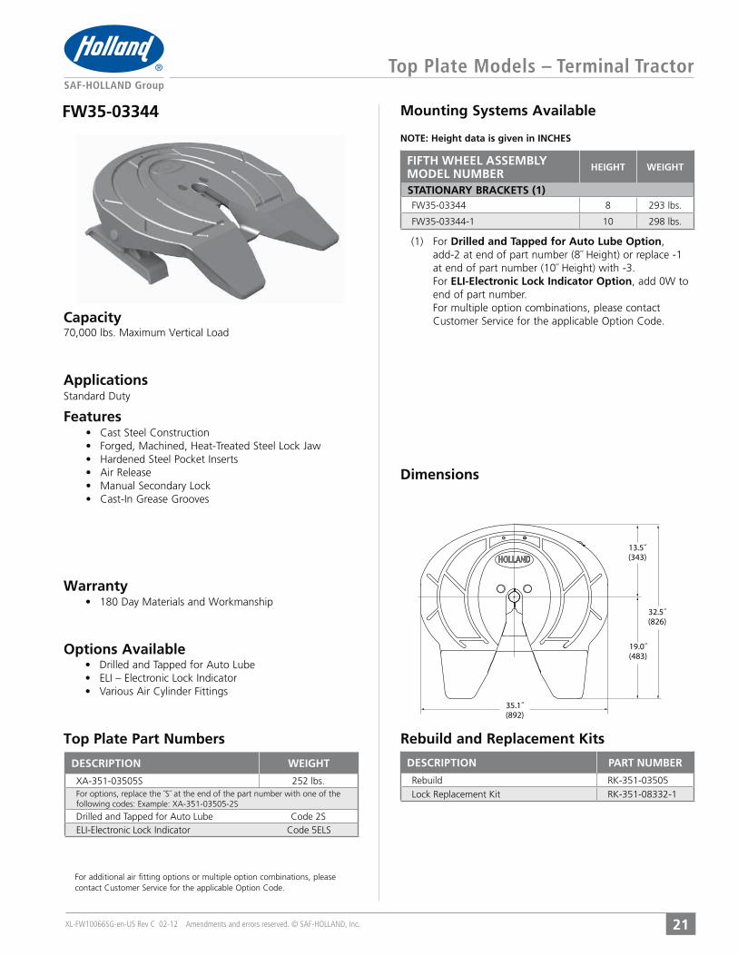
Top Plate Models – Terminal Tractor
21
FW35-03344NOTE: Height data is given in INCHES
(1) For Drilled and Tapped for Auto Lube Option, add-2 at end of part number (8˝ Height) or replace -1 at end of part number (10˝ Height) with -3.
For ELI-Electronic Lock Indicator Option, add 0W to end of part number.
For multiple option combinations, please contact
35.1˝(892)
13.5˝(343)
32.5˝(826)
19.0˝(483)
DESCRIPTION PART NUMBERDESCRIPTION WEIGHT
252 lbs.
For additional air fitting options or multiple option combinations, please
Rebuild and Replacement KitsTop Plate Part Numbers
FIFTH WHEEL ASSEMBLYMODEL NUMBER
HEIGHT WEIGHT
STATIONARY BRACKETS (1)FW35-03344 8 293 lbs.
FW35-03344-1 10 298 lbs.
XL-FW10066SG-en-US Rev C 02-12 Amendments and errors reserved. © SAF-HOLLAND, Inc.
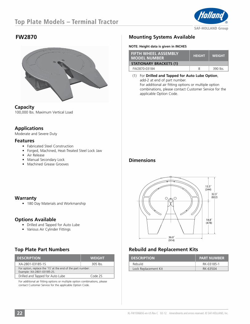
Top Plate Models – Terminal Tractor
22
Dimensions
Mounting Systems Available
Options Available
Warranty
Features
Applications
Capacity
FW2870
NOTE: Height data is given in INCHES
(1) For Drilled and Tapped for Auto Lube Option, add-2 at end of part number. For additional air fitting options or multiple option
36.0˝(914)
13.5˝(344)
32.3˝(822)
18.8˝(478)
DESCRIPTION PART NUMBERDESCRIPTION WEIGHT
305 lbs.
For additional air fitting options or multiple option combinations, please
Rebuild and Replacement KitsTop Plate Part Numbers
FIFTH WHEEL ASSEMBLYMODEL NUMBER
HEIGHT WEIGHT
STATIONARY BRACKETS (1)FW2870-03184 8 390 lbs.

XL-FW10066SG-en-US Rev C 02-12 Amendments and errors reserved. © SAF-HOLLAND, Inc.
Rebuild and Replacement KitsTop Plate Part Numbers
Dimensions
Mounting Systems Available
Options Available
Warranty
Features
Applications
Capacity
Top Plate Models – Terminal Tractor / Fully Oscillating
23
FW1560-C
NOTE: Height data is given in INCHES
(1) For Manual Release, replace C at the end of the part number with B.
25.8˝(656)
20.1˝(510)
13.5˝(344)
33.5˝(852)
20.0˝(508)
36.0˝(914)
DESCRIPTION WEIGHT
265 lbs.
DESCRIPTION PART NUMBER
FIFTH WHEEL ASSEMBLYMODEL NUMBER
HEIGHT WEIGHT
STATIONARY MOUNTING PLATE (1)FW1560-C 11 520 lbs.

XL-FW10066SG-en-US Rev C 02-12 Amendments and errors reserved. © SAF-HOLLAND, Inc.
Top Plate Models – Terminal Tractor / Elevating
24
Dimensions
Features
Applications
Capacity
FW2800/2900NOTE: Height data is given in INCHES
Rebuild and Replacement KitsTop Plate Part Numbers
Mounting Systems Available
(1) For Lock Down Option, add -87 to the end of the part number. Add 56 lbs. to weight.
Hydraulic Lift Accessories Available
Cylinder) – RK-2800-11G
(Twin Cylinder) – RK-2800-41-GRK-2800-20-G
RK-2800-30-G
RK-2800-50
Options Available
Warranty
(For frequent over-the-road usage on public streets or highways.)
Top Plate
Hydraulic Lift Mechanism
36.0˝(914)
13.5˝(344)
32.3˝(822)
18.8˝(478)
DESCRIPTION PART NUMBERDESCRIPTION WEIGHT
300 lbs.
FIFTH WHEEL ASSEMBLYMODEL NUMBER
HEIGHT WEIGHT
SINGLE CYLINDER (1)FW2900-X 10-24 1524 lbs.
FW2800-X 10-29 1662 lbs.
TWIN CYLINDERFW2900-5X 11-26 1920 lbs.
FW2800-5X 12-30 2105 lbs.
XL-FW10066SG-en-US Rev C 02-12 Amendments and errors reserved. © SAF-HOLLAND, Inc.
Top Plate Models – Light Commercial
25
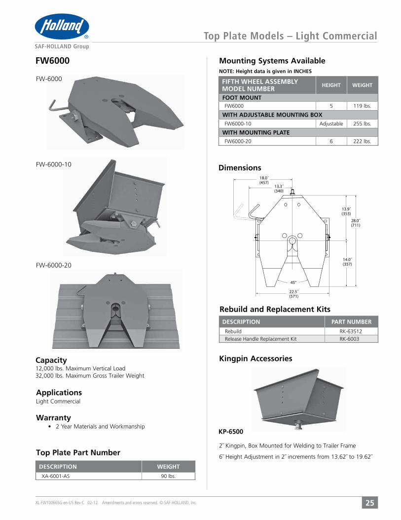
FW6000 Mounting Systems Available
Dimensions
Capacity
Rebuild and Replacement Kits
NOTE: Height data is given in INCHES
Warranty
Kingpin Accessories
Applications
32,000 lbs. Maximum Gross Trailer Weight
FW-6000-10
18.0˝(457)
22.5˝(571)
13.3˝(340)
13.9˝(353)
28.0˝(711)
14.0˝(357)
45°
FW-6000
FW-6000-20
Top Plate Part Number
DESCRIPTION WEIGHT
90 lbs.
DESCRIPTION PART NUMBER
FIFTH WHEEL ASSEMBLYMODEL NUMBER
HEIGHT WEIGHT
FOOT MOUNTFW6000 5 119 lbs.
WITH ADJUSTABLE MOUNTING BOXFW6000-10 255 lbs.
WITH MOUNTING PLATEFW6000-20 6 222 lbs.
KP-6500
Top Plate Models – Light Commercial
26 XL-FW10066SG-en-US Rev C 02-12 Amendments and errors reserved. © SAF-HOLLAND, Inc.
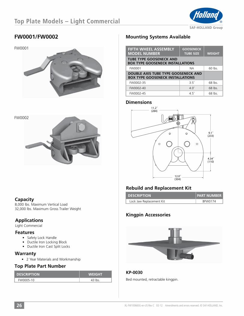
FW0001/FW0002 Mounting Systems Available
Dimensions
Kingpin Accessories
Features
Applications
KP-0030
Bed mounted, retractable kingpin.
Capacity
Warranty
32,000 lbs. Maximum Gross Trailer Weight
11.2˝(284)
12.0˝(304)
9.1˝(233)
4.34˝(110)
Top Plate Part Number
FW0001
FW0002
Rebuild and Replacement Kit
DESCRIPTION WEIGHT
FW0005-10 43 lbs.
DESCRIPTION PART NUMBER
BFW0174
FIFTH WHEEL ASSEMBLYMODEL NUMBER
GOOSENECKTUBE SIZE WEIGHT
TUBE TYPE GOOSENECK ANDBOX TYPE GOOSENECK INSTALLATIONS
FW0001 60 lbs.
DOUBLE AXIS TUBE TYPE GOOSENECK ANDBOX TYPE GOOSENECK INSTALLATIONSFW0002-35 3.5˝ 68 lbs.
FW0002-40 4.0˝ 68 lbs.
FW0002-45 4.5˝ 68 lbs.

CONTENTS:
STATIONARY, SLIDING, NO-TILT, AND KOMPENSATOR MOUNTS
APPLICATIONS
FEATURES
MOUNTING SYSTEM DIMENSIONS
FIFTH WHEEL ASSEMBLY PART NUMBERS
FIFTH WHEEL ASSEMBLY WEIGHTS
FIFTH WHEEL
MOUNTING
SYSTEMS

XL-FW10066SG-en-US Rev C 02-12 Amendments and errors reserved. © SAF-HOLLAND, Inc.
Mounting Systems / Stationary Mounts
28
Part Numbers
Features
Applications
Dimensions
available on FW16, FW31 and FW35.(3) For options, replace the 00 at the end of the part
number with the appropriate two digit code. For multiple option combinations, please contact Customer
Air Release and FW17 – Option Code-80ELI (Electronic Lock Indicator) – Available on FW31 and FW35 – Option Code-ELManual Secondary Lock – Available on FW31 and FW35 – Option Code-02Drilled and Tapped for Auto Lube
Option Code-24Left Hand Dolly Release Handle – Available on FW35 – Option Code-28Corrugated Mounting Plate – Available on FW31 and FW35 – Option Code-01
ease of installation when using corrugated mounting plates.
* A flat or corrugated mounting plate is required for foot mount brackets.
Foot Mount
1.0˝(25)
8.5˝(215)
6.5˝(165)
1.0˝(26) TYP.
.6˝(17) TYP.
8.0˝(203) 16.0˝
(406) 18.0˝(457)
FIFTH WHEEL ASSEMBLYMODEL NUMBER (1) (2) (3)
HEIGHTWEIGHT
(4)6˝ 227 lbs.
7˝ 233 lbs.
8˝ 238 lbs.9˝ 243 lbs.
FIFTH WHEELMODEL
MANUALRELEASE
AIRRELEASE
FW17 45 lbs. 51 lbs.
FW16 42 lbs.
FW31 94 lbs. 98 lbs.
FW35 69 lbs. 73 lbs.65 lbs. 72 lbs.

XL-FW10066SG-en-US Rev C 02-12 Amendments and errors reserved. © SAF-HOLLAND, Inc.
Mounting Systems / Stationary Mounts
29
Part Numbers
Features
Applications
Dimensions
available on FW16, FW31 and FW35.(3) For options, replace the 00 at the end of the part
number with the appropriate two digit code. For multiple option combinations, please contact Customer
Air Release and FW17 – Option Code-80ELI (Electronic Lock Indicator) – Available on FW31 and FW35 – Option Code-ELManual Secondary Lock – Available on FW31 and FW35 – Option Code-02Drilled and Tapped for Auto Lube
Option Code-24Left Hand Dolly Release Handle – Available on FW35 – Option Code-28
Integrated Plate Mount
1.3˝(34)
4.0˝(101)
10 x 8.5˝( 17)
18.5˝(469)
40.0˝(1016)
37.2˝(946)
TYP
FIFTH WHEEL ASSEMBLYMODEL NUMBER (1) (2) (3)
HEIGHTWEIGHT
(4)6˝ 243 lbs.
7˝ 251 lbs.
8˝ 258 lbs.9˝ 254 lbs.
FIFTH WHEELMODEL
MANUALRELEASE
AIRRELEASE
FW17 45 lbs. 51 lbs.
FW16 42 lbs.
FW31 94 lbs. 98 lbs.
FW35 69 lbs. 73 lbs.65 lbs. 72 lbs.
XL-FW10066SG-en-US Rev C 02-12 Amendments and errors reserved. © SAF-HOLLAND, Inc.
Mounting Systems – Stationary Mounts
30
Part Numbers
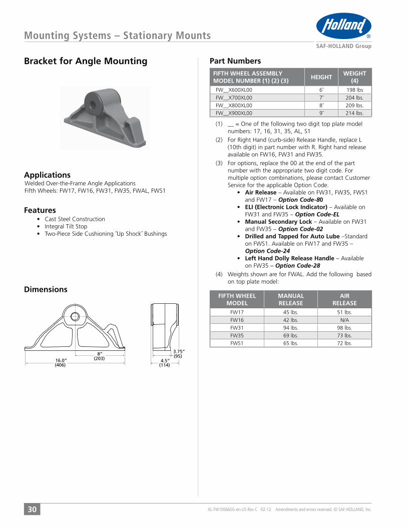
Applications
Dimensions
Features
available on FW16, FW31 and FW35.(3) For options, replace the 00 at the end of the part
number with the appropriate two digit code. For multiple option combinations, please contact Customer
Air Release and FW17 – Option Code-80ELI (Electronic Lock Indicator) – Available on FW31 and FW35 – Option Code-ELManual Secondary Lock – Available on FW31 and FW35 – Option Code-02Drilled and Tapped for Auto Lube
Option Code-24Left Hand Dolly Release Handle – Available on FW35 – Option Code-28
Bracket for Angle Mounting
8”(203)16.0”
(406)
3.75”(95)
4.5”(114)
FIFTH WHEEL ASSEMBLYMODEL NUMBER (1) (2) (3)
HEIGHTWEIGHT
(4)6˝ 198 lbs
7˝ 204 lbs.
8˝ 209 lbs.9˝ 214 lbs.
FIFTH WHEELMODEL
MANUALRELEASE
AIRRELEASE
FW17 45 lbs. 51 lbs.
FW16 42 lbs.
FW31 94 lbs. 98 lbs.
FW35 69 lbs. 73 lbs.65 lbs. 72 lbs.
XL-FW10066SG-en-US Rev C 02-12 Amendments and errors reserved. © SAF-HOLLAND, Inc.
Mounting Systems – Stationary Mounts
31
Part Numbers
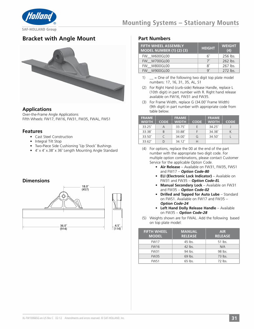
Features
Applications
Dimensions
available on FW16, FW31 and FW35.(3) For Frame Width, replace G (34.00˝ Frame Width)
(9th digit) in part number with appropriate code from table below.
(4) For options, replace the 00 at the end of the part number with the appropriate two digit code. For multiple option combinations, please contact Customer
Air Releaseand FW17 – Option Code-80ELI (Electronic Lock Indicator) – Available on FW31 and FW35 – Option Code-ELManual Secondary Lock – Available on FW31 and FW35 – Option Code-02Drilled and Tapped for Auto Lube
Option Code-24Left Hand Dolly Release Handle – Available on FW35 – Option Code-28
Bracket with Angle Mount
36.0˝(914)
4.5˝(114)
18.0˝(457)
FRAMEWIDTH CODE
FRAMEWIDTH CODE
FRAMEWIDTH CODE
33.25˝ A 33.75˝ E 34.25˝ J
33.38˝ B 33.88˝ F 34.38˝ K
33.50˝ C 34.00˝ G 34.50˝ L
33.62˝ D 34.12˝ H
FIFTH WHEEL ASSEMBLYMODEL NUMBER (1) (2) (3)
HEIGHTWEIGHT
(4)
6˝ 256 lbs.7˝ 262 lbs.8˝ 267 lbs.9˝ 272 lbs.
FIFTH WHEELMODEL
MANUALRELEASE
AIRRELEASE
FW17 45 lbs. 51 lbs.
FW16 42 lbs.
FW31 94 lbs. 98 lbs.
FW35 69 lbs. 73 lbs.65 lbs. 72 lbs.
XL-FW10066SG-en-US Rev C 02-12 Amendments and errors reserved. © SAF-HOLLAND, Inc.
Mounting Systems – Sliding Mounts
32
Part Numbers
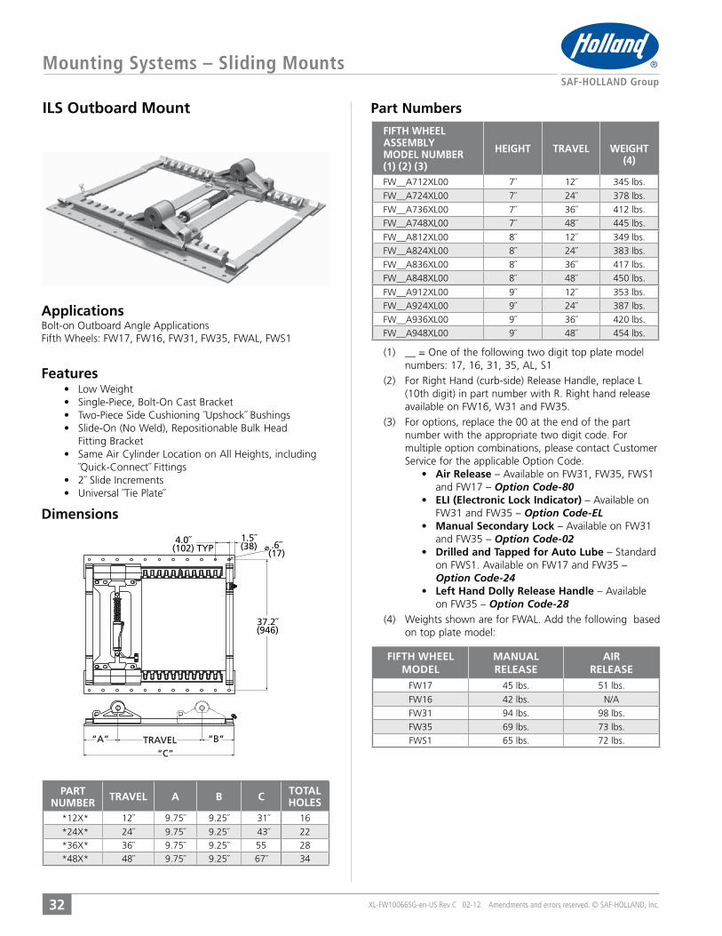
Features
Applications
Dimensions
available on FW16, W31 and FW35.(3) For options, replace the 00 at the end of the part
number with the appropriate two digit code. For multiple option combinations, please contact Customer
Air Releaseand FW17 – Option Code-80ELI (Electronic Lock Indicator) – Available on FW31 and FW35 – Option Code-ELManual Secondary Lock – Available on FW31 and FW35 – Option Code-02Drilled and Tapped for Auto Lube
Option Code-24Left Hand Dolly Release Handle – Available on FW35 – Option Code-28
Fitting Bracket
˝Quick-Connect˝ Fittings
ILS Outboard Mount
TRAVEL “B”
“C”
“A”
37.2˝(946)
1.5˝(38) .6˝
(17)4.0˝
(102) TYP
PART NUMBER TRAVEL A B C TOTAL
HOLES*12X* 12˝ 9.75˝ 9.25˝ 31˝ 16
*24X* 24˝ 9.75˝ 9.25˝ 43˝ 22*36X* 36˝ 9.75˝ 9.25˝ 55 28*48X* 48˝ 9.75˝ 9.25˝ 67˝ 34
FIFTH WHEEL ASSEMBLYMODEL NUMBER(1) (2) (3)
HEIGHT TRAVEL WEIGHT(4)
7˝ 12˝ 345 lbs.
7˝ 24˝ 378 lbs.
7˝ 36˝ 412 lbs.7˝ 48˝ 445 lbs.
8˝ 12˝ 349 lbs.8˝ 24˝ 383 lbs.
8˝ 36˝ 417 lbs.8˝ 48˝ 450 lbs.
9˝ 12˝ 353 lbs.9˝ 24˝ 387 lbs.
9˝ 36˝ 420 lbs.9˝ 48˝ 454 lbs.
FIFTH WHEELMODEL
MANUALRELEASE
AIRRELEASE
FW17 45 lbs. 51 lbs.
FW16 42 lbs.
FW31 94 lbs. 98 lbs.
FW35 69 lbs. 73 lbs.65 lbs. 72 lbs.

XL-FW10066SG-en-US Rev C 02-12 Amendments and errors reserved. © SAF-HOLLAND, Inc.
Mounting Systems – Sliding Mounts
33
Part Numbers
Features
Applications
Dimensions
available on FW16, FW31 and FW35.(3) For options, replace the 00 at the end of the part
number with the appropriate two digit code. For multiple option combinations, please contact Customer
Air Releaseand FW17 – Option Code-80ELI (Electronic Lock Indicator) – Available on FW31 and FW35 – Option Code-ELManual Secondary Lock – Available on FW31 and FW35 – Option Code-02Drilled and Tapped for Auto Lube
Option Code-24Left Hand Dolly Release Handle – Available on FW35 – Option Code-28
Fitting Bracket
˝Quick-Connect˝ Fittings
ILS Inboard Mount(Over-the-Frame)
TRAVEL “B”
“C”
“A”
35.5”(901)
PART NUMBER TRAVEL A B C*12X* 12˝ 9.75˝ 9.25˝ 31˝
*24X* 24˝ 9.75˝ 9.25˝ 43˝
*36X* 36˝ 9.75˝ 9.25˝ 55˝*48X* 48˝ 9.75˝ 9.25˝ 67˝
FIFTH WHEEL ASSEMBLYMODEL NUMBER(1) (2) (3)
HEIGHT TRAVEL WEIGHT(4)
7˝ 12˝ 330 lbs.
7˝ 24˝ 358 lbs.
7˝ 36˝ 386 lbs.7˝ 48˝ 414 lbs.
8˝ 12˝ 335 lbs.8˝ 24˝ 363 lbs.
8˝ 36˝ 391 lbs.8˝ 48˝ 419 lbs.
9˝ 12˝ 339 lbs.9˝ 24˝ 367 lbs.
9˝ 36˝ 395 lbs.9˝ 48˝ 423 lbs.
FIFTH WHEELMODEL
MANUALRELEASE
AIRRELEASE
FW17 45 lbs. 51 lbs.
FW16 42 lbs.
FW31 94 lbs. 98 lbs.
FW35 69 lbs. 73 lbs.65 lbs. 72 lbs.
XL-FW10066SG-en-US Rev C 02-12 Amendments and errors reserved. © SAF-HOLLAND, Inc.
Mounting Systems – FW0070 Stationary Mounts
34
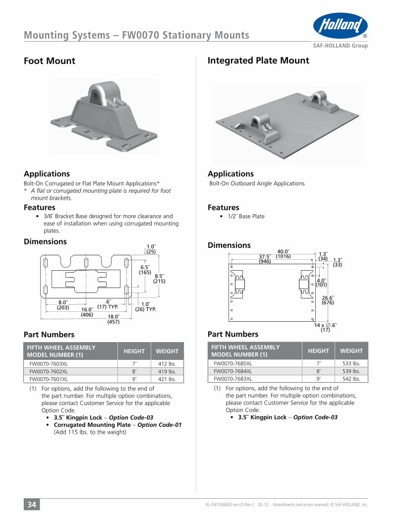
Foot Mount
Features Features
Applications Applications
Part Numbers
Dimensions
Part Numbers
Dimensions
3/8˝ Bracket Base designed for more clearance and ease of installation when using corrugated mounting plates.
Integrated Plate Mount
(1) For options, add the following to the end of the part number. For multiple option combinations,
3.5˝ Kingpin Lock – Option Code-03 Corrugated Mounting Plate – Option Code-01
(Add 115 lbs. to the weight)
(1) For options, add the following to the end of the part number. For multiple option combinations,
3.5˝ Kingpin Lock – Option Code-03
40.0˝(1016) 1.3˝
(34) 1.3˝(33)
4.0˝(101)
26.6˝(676)
14 x ∅.6˝(17)
37.5˝(946)
1.0˝(25)
8.5˝(215)
6.5˝(165)
1.0˝(26) TYP.
.6˝(17) TYP.
8.0˝(203) 16.0˝
(406) 18.0˝(457)
FIFTH WHEEL ASSEMBLYMODEL NUMBER (1)
HEIGHT WEIGHT
7˝ 412 lbs.
8˝ 419 lbs.9˝ 421 lbs.
FIFTH WHEEL ASSEMBLYMODEL NUMBER (1)
HEIGHT WEIGHT
7˝ 533 lbs.
8˝ 539 lbs.9˝ 542 lbs.
* A flat or corrugated mounting plate is required for foot mount brackets.
XL-FW10066SG-en-US Rev C 02-12 Amendments and errors reserved. © SAF-HOLLAND, Inc.
Mounting Systems – FW0070 Stationary Mounts
35
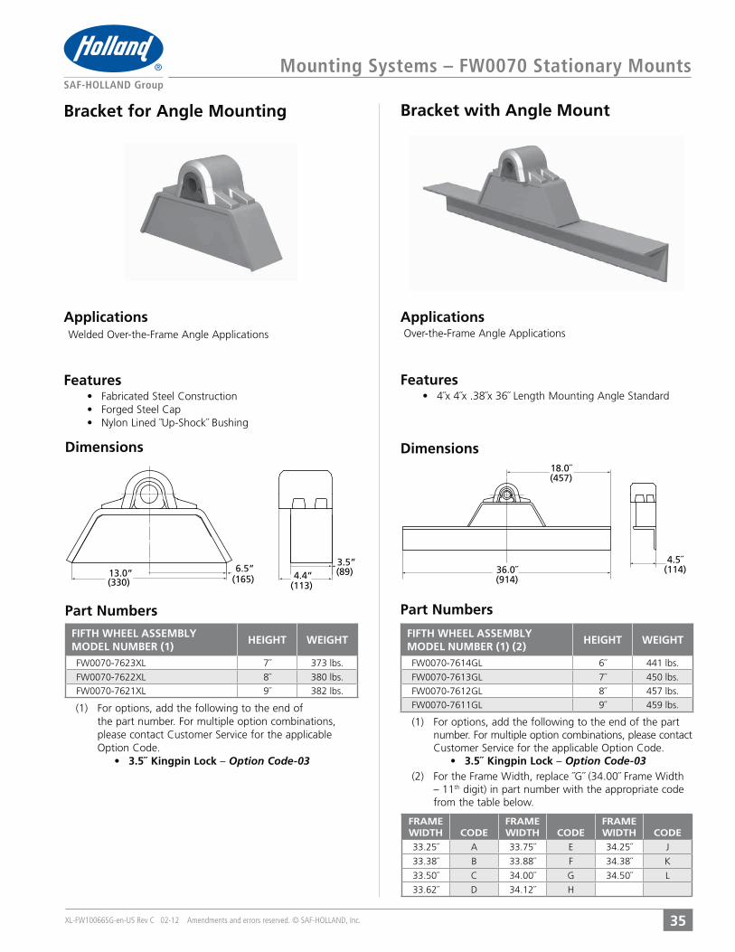
Bracket for Angle Mounting
Features
Applications
Dimensions
Applications
Part Numbers
Dimensions
Part Numbers
Bracket with Angle Mount
(1) For options, add the following to the end of the part number. For multiple option combinations, please contact
3.5˝ Kingpin Lock – Option Code-03(2) For the Frame Width, replace ˝G˝ (34.00˝ Frame Width
– 11th digit) in part number with the appropriate code from the table below.
(1) For options, add the following to the end of the part number. For multiple option combinations,
3.5˝ Kingpin Lock – Option Code-03
6.5”(165)
13.0”(330)
3.5”(89)4.4”
(113)
36.0˝(914)
4.5˝(114)
18.0˝(457)
Features
FRAMEWIDTH CODE
FRAMEWIDTH CODE
FRAMEWIDTH CODE
33.25˝ A 33.75˝ E 34.25˝ J
33.38˝ B 33.88˝ F 34.38˝ K
33.50˝ C 34.00˝ G 34.50˝ L
33.62˝ D 34.12˝ H
FIFTH WHEEL ASSEMBLYMODEL NUMBER (1)
HEIGHT WEIGHT
7˝ 373 lbs.
8˝ 380 lbs.9˝ 382 lbs.
FIFTH WHEEL ASSEMBLYMODEL NUMBER (1) (2)
HEIGHT WEIGHT
6˝ 441 lbs.
7˝ 450 lbs.
8˝ 457 lbs.9˝ 459 lbs.
XL-FW10066SG-en-US Rev C 02-12 Amendments and errors reserved. © SAF-HOLLAND, Inc.
Mounting Systems – FW0070 Sliding Mounts
36
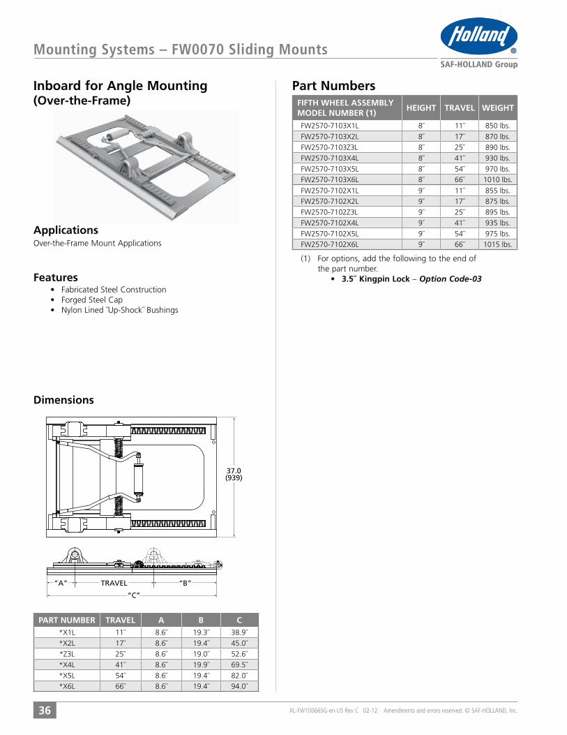
Inboard for Angle Mounting
36
Part Numbers
Dimensions
Applications
(1) For options, add the following to the end of the part number.
3.5˝ Kingpin Lock – Option Code-03
(Over-the-Frame)
Features
“C”
37.0(939)
“A” TRAVEL “B”
PART NUMBER TRAVEL A B C11˝ 8.6˝ 19.3˝ 38.9˝
17˝ 8.6˝ 19.4˝ 45.0˝
25˝ 8.6˝ 19.0˝ 52.6˝
41˝ 8.6˝ 19.9˝ 69.5˝
54˝ 8.6˝ 19.4˝ 82.0˝66˝ 8.6˝ 19.4˝ 94.0˝
FIFTH WHEEL ASSEMBLYMODEL NUMBER (1)
HEIGHT TRAVEL WEIGHT
8˝ 11˝ 850 lbs.
8˝ 17˝ 870 lbs.
8˝ 25˝ 890 lbs.
8˝ 41˝ 930 lbs.
8˝ 54˝ 970 lbs.8˝ 66˝ 1010 lbs.
9˝ 11˝ 855 lbs.9˝ 17˝ 875 lbs.
9˝ 25˝ 895 lbs.
9˝ 41˝ 935 lbs.
9˝ 54˝ 975 lbs.9˝ 66˝ 1015 lbs.

XL-FW10066SG-en-US Rev C 02-12 Amendments and errors reserved. © SAF-HOLLAND, Inc.
Mounting Systems – No-Tilt Stationary Mounts
37
Outboard Mount
37
Part Numbers
Dimensions
Applications
Features
(2) For options, replace the 06 at the end of the part number with the appropriate two digit code.
Manual Secondary Lock – Option Code-34
(34)
26.6”
37.2”1.3”
40.0”(1016)
(101)
(33)
1.4”
(946)
(676)
4.0”
FIFTH WHEEL ASSEMBLYMODEL NUMBER (1) (2)
HEIGHT WEIGHT
8˝ 489 lbs.9˝ 491 lbs.

XL-FW10066SG-en-US Rev C 02-12 Amendments and errors reserved. © SAF-HOLLAND, Inc.
Mounting Systems – No-Tilt Stationary Mounts
38
Inboard For Angle Mounting
38
Part Numbers
Applications
Dimensions
Features
(2) For options, replace the 06 at the end of the part number with the appropriate two digit code.
Manual Secondary Lock – Option Code-34
3/8
(Over-the-Frame)
(1016)40.0”
26.6”(676)
FIFTH WHEEL ASSEMBLYMODEL NUMBER (1) (2)
HEIGHT WEIGHT
8˝ 454 lbs.

XL-FW10066SG-en-US Rev C 02-12 Amendments and errors reserved. © SAF-HOLLAND, Inc.
Mounting Systems – No-Tilt Sliding Mounts
39
Outboard Mount
39
Part Numbers
Dimensions
Applications
Features
(2) For options, replace the 06 at the end of the part number with the appropriate two digit code. For multiple option combinations, please contact Customer
Option Code-34
“B”
∅.7˝(17)
4.0˝(101)
8.0˝(203)
37.2˝(946)
39.5˝(1003)
1.1̋(27)
TRAVEL“A”“C”
PART NUMBER TRAVEL A B C14˝ 14.63˝ 11.57˝ 42.2˝
20˝ 14.63˝ 11.57˝ 46.6˝
32˝ 14.63˝ 11.57˝ 58.2˝44˝ 14.63˝ 11.57˝ 70.2˝
FIFTH WHEEL ASSEMBLYMODEL NUMBER (1) (2)
HEIGHT TRAVEL WEIGHT
9˝ 14˝ 516 lbs
9˝ 20˝ 547 lbs
9˝ 32˝ 580 lbs9˝ 44˝ 620 lbs
10˝ 14˝ 571 lbs10˝ 20˝ 598 lbs
10˝ 32˝ 641 lbs10˝ 44˝ 682 lbs
XL-FW10066SG-en-US Rev C 02-12 Amendments and errors reserved. © SAF-HOLLAND, Inc.
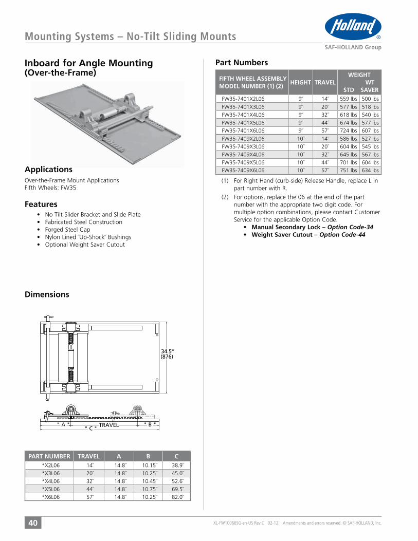
Mounting Systems – No-Tilt Sliding Mounts
40
Inboard for Angle Mounting Part Numbers
(2) For options, replace the 06 at the end of the part number with the appropriate two digit code. For multiple option combinations, please contact Customer
Option Code-34Option Code-44
(Over-the-Frame)
" A " " B "TRAVEL" C "
34.5”(876)
PART NUMBER TRAVEL A B C14˝ 14.8˝ 10.15˝ 38.9˝
20˝ 14.8˝ 10.25˝ 45.0˝
32˝ 14.8˝ 10.45˝ 52.6˝
44˝ 14.8˝ 10.75˝ 69.5˝57˝ 14.8˝ 10.25˝ 82.0˝
FIFTH WHEEL ASSEMBLYMODEL NUMBER (1) (2)
HEIGHT TRAVELWEIGHT
WT STD SAVER
9˝ 14˝ 559 lbs 500 lbs
9˝ 20˝ 577 lbs 518 lbs
9˝ 32˝ 618 lbs 540 lbs
9˝ 44˝ 674 lbs 577 lbs9˝ 57˝ 724 lbs 607 lbs
10˝ 14˝ 586 lbs 527 lbs10˝ 20˝ 604 lbs 545 lbs
10˝ 32˝ 645 lbs 567 lbs
10˝ 44˝ 701 lbs 604 lbs10˝ 57˝ 751 lbs 634 lbs
Dimensions
Applications
Features

XL-FW10066SG-en-US Rev C 02-12 Amendments and errors reserved. © SAF-HOLLAND, Inc.
Mounting Systems – Kompensator Stationary Mounts
41
Outboard Plate Mount Part Numbers
Applications
Dimensions
Features
FW35.(2) For options, add the appropriate two digit code to
the end of the part number. For multiple option
FW7040. Available on FW35. Option Code-34
Option Code-24Option Code-19
(Add 5 lbs. to weight)Option Code-13
Available on FW7040. Option Code-03
3.0”40.0”(76)
(946)(1016)37.2”
30.0”(762)
.4”(9)
FIFTH WHEEL ASSEMBLYMODEL NUMBER (1) (2)
HEIGHT WEIGHT
10˝ 586 lbs.
12˝ 651 lbs.13˝ 660 lbs.
FIFTH WHEEL ASSEMBLYMODEL NUMBER (2)
HEIGHT WEIGHT
10˝ 749 lbs.
12˝ 821 lbs.13˝ 836 lbs.
XL-FW10066SG-en-US Rev C 02-12 Amendments and errors reserved. © SAF-HOLLAND, Inc.
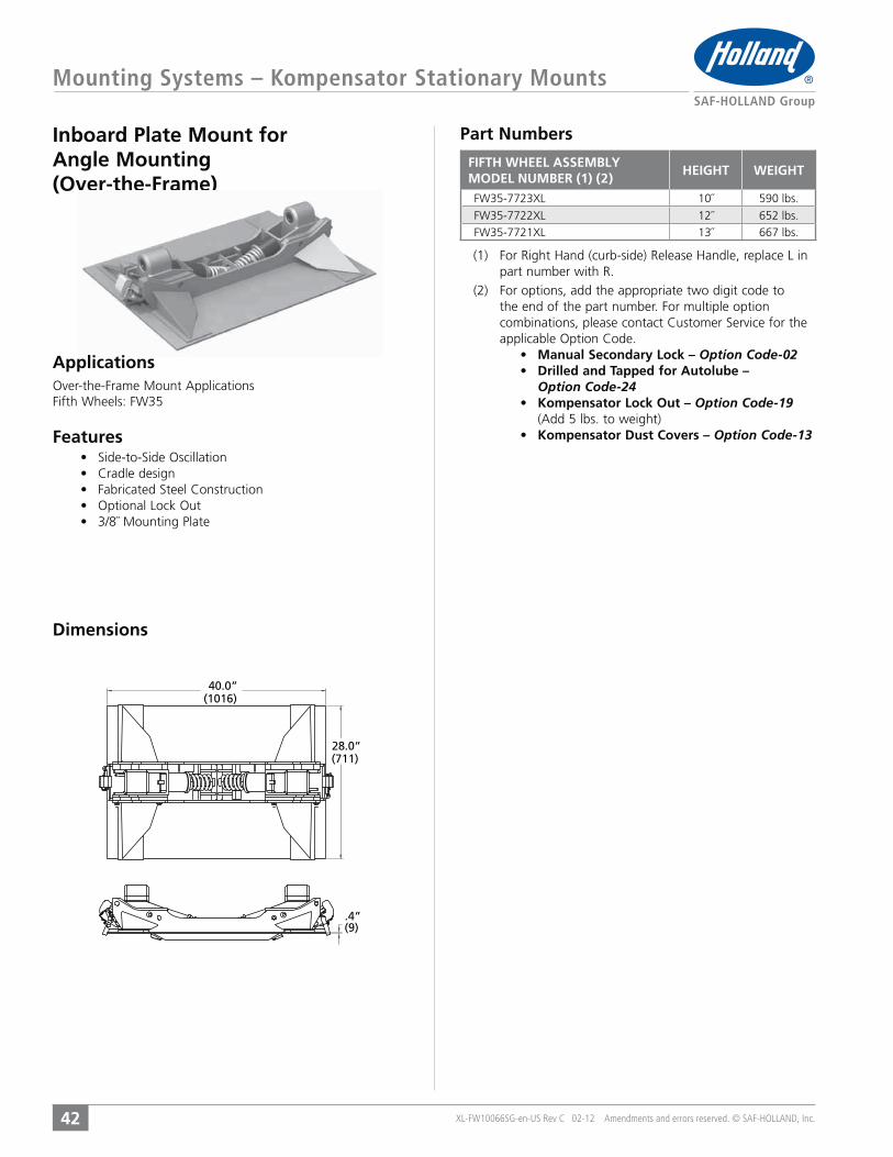
Mounting Systems – Kompensator Stationary Mounts
42
Inboard Plate Mount for Angle Mounting(Over-the-Frame)
Part Numbers
(2) For options, add the appropriate two digit code to the end of the part number. For multiple option
Option Code-02
Option Code-24Option Code-19
(Add 5 lbs. to weight)Option Code-13
.4”(9)
40.0”(1016)
28.0”(711)
FIFTH WHEEL ASSEMBLYMODEL NUMBER (1) (2)
HEIGHT WEIGHT
10˝ 590 lbs.
12˝ 652 lbs.13˝ 667 lbs.
Dimensions
Applications
Features

XL-FW10066SG-en-US Rev C 02-12 Amendments and errors reserved. © SAF-HOLLAND, Inc.
Mounting Systems – Kompensator Stationary Mounts
43
Inboard for Angle Mounting (Over-the-Frame)
Part Numbers
(2) For options, add the appropriate two digit code to the end of the part number. For multiple option
Option Code-02
Option Code-24Option Code-19
(Add 5 lbs. to weight)Option Code-13
36.0”(914)
28.5”(724)
.2”(6)
FIFTH WHEEL ASSEMBLYMODEL NUMBER (1) (2)
HEIGHT WEIGHT
9˝ 490 lbs.
11˝ 532 lbs.12˝ 547 lbs.
Applications
Dimensions
Features

XL-FW10066SG-en-US Rev C 02-12 Amendments and errors reserved. © SAF-HOLLAND, Inc.
Mounting Systems – Kompensator Stationary Mounts
44
Inboard with Angle Mount (Over-the-Frame)
Part Numbers
Dimensions
(2) For options, add the appropriate two digit code to the end of the part number. For multiple option
Option Code-02
Option Code-24Option Code-19
(Add 5 lbs. to weight)Option Code-13
(3) For the Frame Width, replace ˝G˝ (34.00˝ Frame Width) (9th digit) in part number with the appropriate code from the table below.
36.0”(914)
28.5”(724)
4.0”(102)
34.0”(864)
FRAMEWIDTH CODE
FRAMEWIDTH CODE
FRAMEWIDTH CODE
33.25˝ A 33.75˝ E 34.25˝ J
33.38˝ B 33.88˝ F 34.38˝ K
33.50˝ C 34.00˝ G 34.50˝ L
33.62˝ D 34.12˝ H
FIFTH WHEEL ASSEMBLYMODEL NUMBER (1, 2, 3)
HEIGHT WEIGHT
10˝ 550 lbs.
12˝ 592 lbs.13˝ 607 lbs.
Applications
Features
XL-FW10066SG-en-US Rev C 02-12 Amendments and errors reserved. © SAF-HOLLAND, Inc.
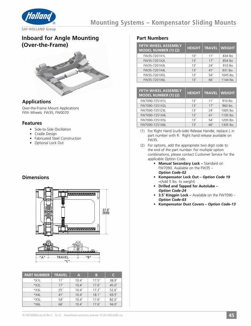
Mounting Systems – Kompensator Sliding Mounts
45
Inboard for Angle Mounting(Over-the-Frame)
Part Numbers
Dimensions
FW35.(2) For options, add the appropriate two digit code to
the end of the part number. For multiple option
FW7090. Available on the FW35 – Option Code-02
Option Code 19 (Add 5 lbs. to weight)
Option Code-24
Available on the FW7090 – Option Code-03
Option Code-13
37.0˝(939)
“B”TRAVEL“A”“C”
PART NUMBER TRAVEL A B C11˝ 10.4˝ 17.5˝ 38.9˝
17˝ 10.4˝ 17.6˝ 45.0˝
25˝ 10.4˝ 17.2˝ 52.6˝
41˝ 10.4˝ 18.1˝ 69.5˝
54˝ 10.4˝ 17.6˝ 82.0˝66˝ 10.4˝ 17.6˝ 94.0˝
FIFTH WHEEL ASSEMBLYMODEL NUMBER (1) (2)
HEIGHT TRAVEL WEIGHT
13˝ 11˝ 834 lbs
13˝ 17˝ 854 lbs
13˝ 24˝ 910 lbs
13˝ 41˝ 931 lbs.
13˝ 54˝ 1045 lbs.13˝ 66˝ 1144 lbs.
FIFTH WHEEL ASSEMBLYMODEL NUMBER (1) (2)
HEIGHT TRAVEL WEIGHT
13˝ 11˝ 910 lbs.
13˝ 17˝ 960 lbs.
13˝ 24˝ 1005 lbs.
13˝ 41˝ 1105 lbs.
13˝ 54˝ 1205 lbs.13˝ 66˝ 1305 lbs.
Applications
Features

XL-FW10066SG-en-US Rev C 02-12 Amendments and errors reserved. © SAF-HOLLAND, Inc.
Custom Service Tools for Fifth Wheels
46
Essential service and checking tools - Specially designed for Holland Fifth Wheel products.
2˝ Fifth Wheel Lock Adjustment ToolsTF-TLN-5001
4000171
3.5˝ Fifth Wheel Lock Adjustment ToolTF-TLN-1500
Slider Spring CompressorTF-TLN-2500
and pins of the slide release mechanisms of Holland sliding fifth
best results, operate with a 5/8˝ socket and ratchet.
2˝ PlugTF-0237This 2˝ plug is designed to assist in lock installation and
FW33, and FW31 fifth wheels.
Fifth Wheel Rebuild StandTF-04229-1The Holland fifth wheel rebuild stand allows top plate rotation for easy access to both bottom and top surfaces of the top plate
and compact storage.
For use with the following top plates:
XA-201, XA-231, and XA-71
CONTENTS:
SEVEN STEPS TO SPECIFYING THE CORRECT FIFTH WHEEL
ITEMS TO CONSIDER BEFORE SPECIFYING A FIFTH WHEEL
SPECIFICATION
GUIDE

XL-FW10066SG-en-US Rev C 02-12 Amendments and errors reserved. © SAF-HOLLAND, Inc.
Specification Guide – Specification Steps
48
number to order. If after completing Steps 1-7 you are unable to determine the correct part number, please contact your SAF-Holland representative for assistance. In the U.S. call 1-888-396-6501. In Canada, call 519-537-2366.
Step 1 ˝Items to consider Before Selecting your Fifth Wheel˝ on Pages 49-53.
Step 2example, tractor, converter dolly, or B-train connection) and the type of trailer your fifth wheel will be connected to (for example, van, tanker, etc.).
Step 3 Using the Holland Fifth Wheel Application Guide on Pages 6-8, determine whether your vehicle will be used in a Standard, Moderate, or Severe duty application.
Step 4 Using the Holland Fifth Wheel Application Guide on Pages 6-8, determine which fifth wheel top plates may be applicable based on the duty type, vehicle and trailer type, and capacity requirements.
Step 5 Page 9, determine the appropriate type of fifth wheel to select based on what options are required (for example, an air release locking system). For specification information
Pages 11-26.
Step 6 Using the Holland Fifth Wheel Application Guide on Pages 6-8, determine the appropriate type of mounting system to select based on the top
either stationary or sliding) and method of tractor frame attachment. For specification information on top plates and their applicable mounting systems, please refer to the appropriate page in the Holland Fifth Wheel
Pages 27-45.
Step 7 A Stationary Mounting Systems Having selected the required stationary mounting system, refer to Page 53 to determine the height required. To determine the correct part number for ordering, please refer to the appropriate page in the Holland Fifth Wheel
Pages 27-45.
B Sliding Mounting Systems Having selected the required sliding mounting system, refer to Page 53 to determine the height and travel required. To determine the correct part number for ordering, please refer to the appropriate page in the Holland Fifth
Pages 27-45.
XL-FW10066SG-en-US Rev C 02-12 Amendments and errors reserved. © SAF-HOLLAND, Inc.
Specification Guide – Items to Consider
49
Fifth Wheel Ratings and CapacitiesThe selection of the proper fifth wheel capacity is the most critical step in specifying a fifth
wheel. The use of a fifth wheel that does not meet the required capacity for the demands of
the application may result in maintenance problems or more importantly, an unsafe operating
condition. The user should specify a higher capacity rating then his normal needs require, taking
into consideration the towed vehicle weight (TVW) to be pulled, maximum drawbar load expected,
vertical load to be carried by the fifth wheel, and type of operation (for example, off-highway
use will normally require a higher capacity rating than on-highway use). The Holland Fifth Wheel
Application Guide on Pages 6-8, can help determine the appropriate fifth wheel capacity required.
Fifth Wheel Options
fifth wheel options offered may help determine the appropriate top plate model. Available
Page 9. For top plate
Pages 11-26.
Fifth Wheel WeightAnother determining factor in selecting a fifth wheel model is the weight. The weight of the fifth
wheel should be a balance between operational cost, strength, and durability. Any additional
weight (above the application requirements), will result in additional expenses such as initial cost,
reduced cargo carrying capacity, and additional fuel cost.
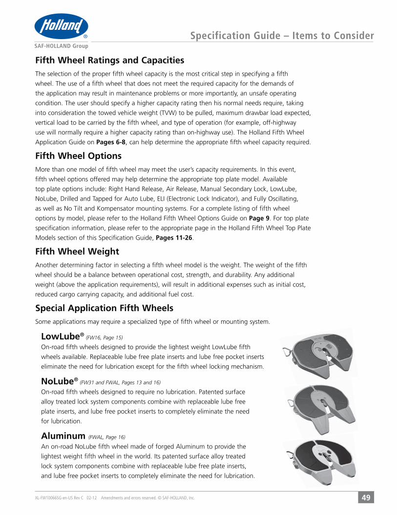
Special Application Fifth Wheels
LowLube® (FW16, Page 15)
eliminate the need for lubrication except for the fifth wheel locking mechanism.
NoLube® (FW31 and FWAL, Pages 13 and 16)
alloy treated lock system components combine with replaceable lube free
plate inserts, and lube free pocket inserts to completely eliminate the need
for lubrication.
Aluminum (FWAL, Page 16)
lock system components combine with replaceable lube free plate inserts,
and lube free pocket inserts to completely eliminate the need for lubrication.
XL-FW10066SG-en-US Rev C 02-12 Amendments and errors reserved. © SAF-HOLLAND, Inc.
Specification Guide – Items to Consider
50
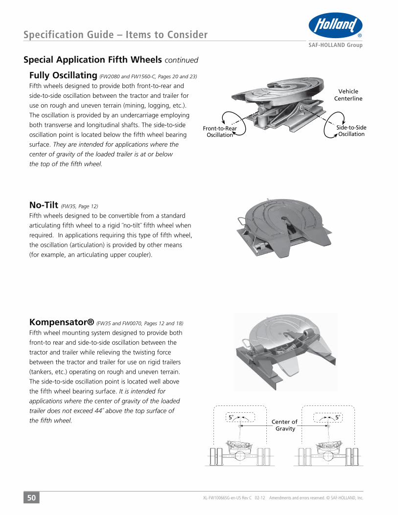
Vehicle Centerline
Front-to-Rear Oscillation
Side-to-Side Oscillation
Special Application Fifth Wheels continued
Fully Oscillating (FW2080 and FW1560-C, Pages 20 and 23) Fifth wheels designed to provide both front-to-rear and
side-to-side oscillation between the tractor and trailer for
use on rough and uneven terrain (mining, logging, etc.).
The oscillation is provided by an undercarriage employing
both transverse and longitudinal shafts. The side-to-side
oscillation point is located below the fifth wheel bearing
surface. They are intended for applications where the
center of gravity of the loaded trailer is at or below
the top of the fifth wheel.
No-Tilt (FW35, Page 12)
Fifth wheels designed to be convertible from a standard
articulating fifth wheel to a rigid ˝no-tilt˝ fifth wheel when
the oscillation (articulation) is provided by other means
(for example, an articulating upper coupler).
Kompensator® (FW35 and FW0070, Pages 12 and 18)
Fifth wheel mounting system designed to provide both
front-to rear and side-to-side oscillation between the
tractor and trailer while relieving the twisting force
between the tractor and trailer for use on rigid trailers
(tankers, etc.) operating on rough and uneven terrain.
The side-to-side oscillation point is located well above
the fifth wheel bearing surface. It is intended for
applications where the center of gravity of the loaded
trailer does not exceed 44˝ above the top surface of
the fifth wheel. 5˚Center of
Gravity
5˚

XL-FW10066SG-en-US Rev C 02-12 Amendments and errors reserved. © SAF-HOLLAND, Inc.
Specification Guide – Items to Consider
51
Fifth Wheel Mounting SystemsAfter determining the appropriate top plate model, the mounting system must
be specified. The first step is to determine whether a standard mounting system
a stationary or sliding mount system.
Stationary Fifth Wheels
where the axle loading, kingpin setting, and vehicle
combination length all remain constant throughout the
sliding fifth wheels but do not offer the application
flexibility of sliding fifth wheels. Based on the suspension
and tractor frame, one of three tractor frame attachment
methods may be specified (Figures 1-3
1) ˝Angle-on-Frame Bracket Mount˝ (low cost and
less torsional rigidity) (Figure 1)
2) ˝Foot Mount˝ (higher cost and high torsional rigidity)
(Figure 2). A flat or corrugated mounting plate is
required for foot mount brackets.
(universal hole pattern for medium torsional rigidity
bolt-on mounting) (Figure 3)
The final step in specifying a stationary mount fifth wheel is
Page 53 for a
discussion of factors to be considered when determining
fifth wheel assembly height requirements.
Figure 1
Figure 2
Figure 3
XL-FW10066SG-en-US Rev C 02-12 Amendments and errors reserved. © SAF-HOLLAND, Inc.
Specification Guide – Items to Consider
52
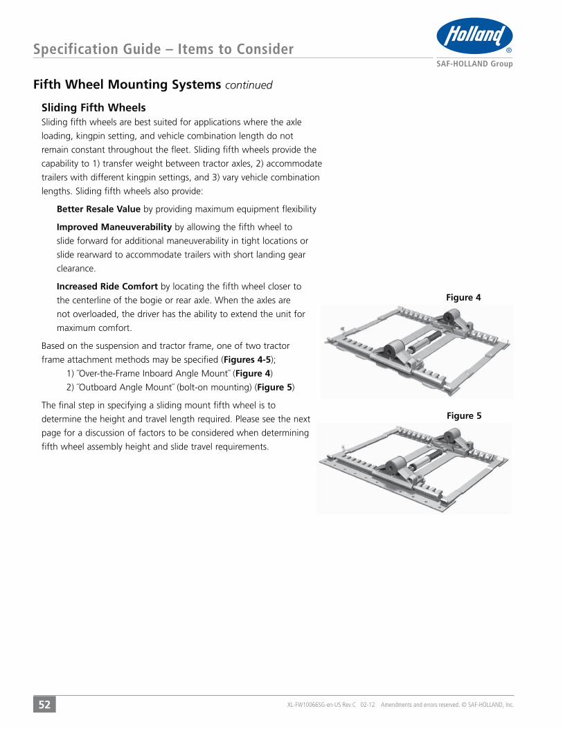
Fifth Wheel Mounting Systems continued
Sliding Fifth Wheels
loading, kingpin setting, and vehicle combination length do not
capability to 1) transfer weight between tractor axles, 2) accommodate
trailers with different kingpin settings, and 3) vary vehicle combination
Better Resale Value by providing maximum equipment flexibility
Improved Maneuverability by allowing the fifth wheel to
slide forward for additional maneuverability in tight locations or
slide rearward to accommodate trailers with short landing gear
clearance.
Increased Ride Comfort by locating the fifth wheel closer to
the centerline of the bogie or rear axle. When the axles are
not overloaded, the driver has the ability to extend the unit for
maximum comfort.
Based on the suspension and tractor frame, one of two tractor
frame attachment methods may be specified (Figures 4-5
Figure 4)
Figure 5)
The final step in specifying a sliding mount fifth wheel is to
page for a discussion of factors to be considered when determining
fifth wheel assembly height and slide travel requirements.
Figure 4
Figure 5

XL-FW10066SG-en-US Rev C 02-12 Amendments and errors reserved. © SAF-HOLLAND, Inc.
Specification Guide – Items to Consider
53
Fifth Wheel Height
Correct fifth wheel height specification is critical because the overall
combination tractor/trailer height cannot exceed 13’6˝. Fifth wheels are
designed to operate with the top plate level, so every attempt should be
made to match the fifth wheel height with the trailer upper coupler (bolster
plate) height. The maximum allowable fifth wheel height is determined by
subtracting the trailer height and tractor frame height from the maximum
ensure the tractor/trailer will not exceed the available articulation damaging
the fifth wheel, tractor frame, or trailer (the lower the fifth wheel height, the
less articulation available, especially in off-road applications). Tire clearance
should also be considered, keeping in mind spring deflection under full load.
Another important consideration in determining fifth wheel height is
developing a standard fleet specification. Having all tractors with the same
mounted fifth wheel height (height from the ground to the top of the fifth
gear before coupling.
Fifth Wheel Slide Travel Length
inability to shift enough kingpin load to the front axle).
Too long a slide length and overloading of the front axle, or interference
slide length also results in unnecessary additional tractor weight and initial
fifth wheel cost.
Fifth Wheel Cost
Users should always balance the initial cost of the unit to be purchased
against the application required, maintenance costs, wear life, and
availability of parts and service. The least expensive initial cost fifth wheel
may have a higher total cost after factoring in operational and repair costs
related to tractor downtime, kingpin replacement, and tractor/trailer frame
options have been recommended for your application, special consideration
should be given to those recommendations. The benefits may offset the
additional initial cost.

54
THIS PAGE INTENTIONALLY LEFT BLANK
XL-FW10066SG-en-US Rev C 02-12 Amendments and errors reserved. © SAF-HOLLAND, Inc.

FIFTH WHEEL
ASSEMBLY
DIMENSIONS37.3˝(946)
40º
4.0˝(102)
1.3˝(32)
18.5˝(470)
40.0˝(1016)
XL-FW10066SG-en-US Rev C 02-12 Amendments and errors reserved. © SAF-HOLLAND, Inc.
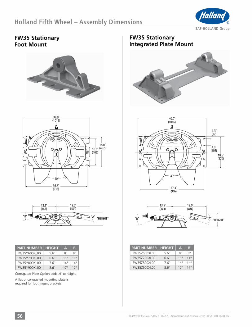
FW35 Stationary Foot Mount
FW35 Stationary Integrated Plate Mount
Holland Fifth Wheel – Assembly Dimensions
56
13.5˝(343)
19.0˝(484)
“B” “A” “HEIGHT”
37.3˝(946)
40º
4.0˝(102)
1.3˝(32)
18.5˝(470)
40.0˝(1016)
13.5˝(343)
36.8˝(935)
40º
16.0˝(406)
18.0˝(457)
39.9˝(1013)
19.0˝(484)
“B” “A” “HEIGHT”
PART NUMBER HEIGHT A B5.6˝ 8º 8º6.6˝ 11º 11º
7.6˝ 14º 14º8.6˝ 17º 17º
A flat or corrugated mounting plate is required for foot mount brackets.
PART NUMBER HEIGHT A B5.6˝ 8º 8º6.6˝ 11º 11º
7.6˝ 14º 14º8.6˝ 17º 17º
XL-FW10066SG-en-US Rev C 02-12 Amendments and errors reserved. © SAF-HOLLAND, Inc.
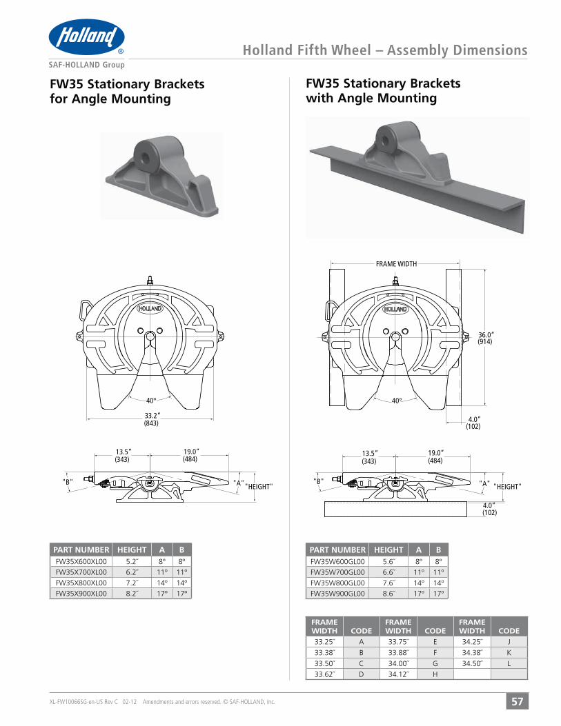
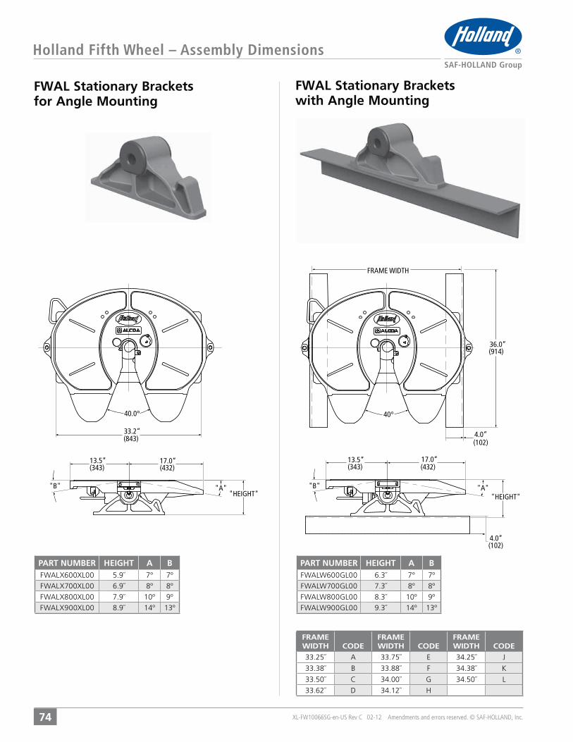
FW35 Stationary Brackets for Angle Mounting
FW35 Stationary Brackets with Angle Mounting
Holland Fifth Wheel – Assembly Dimensions
57
FRAME WIDTH
36.0”(914)
4.0”(102)
40°
"B" "A"
19.0”(484)
13.5”(343)
"HEIGHT"
4.0”(102)
33.2”(843)
40°
"B" "A"
19.0”(484)
13.5”(343)
"HEIGHT"
PART NUMBER HEIGHT A B5.2˝ 8º 8º6.2˝ 11º 11º
7.2˝ 14º 14º8.2˝ 17º 17º
PART NUMBER HEIGHT A B5.6˝ 8º 8º6.6˝ 11º 11º
7.6˝ 14º 14º8.6˝ 17º 17º
FRAMEWIDTH CODE
FRAMEWIDTH CODE
FRAMEWIDTH CODE
33.25˝ A 33.75˝ E 34.25˝ J
33.38˝ B 33.88˝ F 34.38˝ K
33.50˝ C 34.00˝ G 34.50˝ L
33.62˝ D 34.12˝ H

XL-FW10066SG-en-US Rev C 02-12 Amendments and errors reserved. © SAF-HOLLAND, Inc.
FW35 Outboard Sliding Mount
FW35 Inboard Sliding Mount
Holland Fifth Wheel – Assembly Dimensions
58
"SLIDE LENGTH"
"A"
35.5”(902)
9.8”(248)
"B""C""HEIGHT"
19.0”(484)
13.5”(343)
“A”
4.0”(102)
40.0”(1016)
37.3”(946)
39.5”(1003)
40º
9.8”(248)“SLIDE LENGTH”
19.0”(484)
13.5”(343)
“C”“B”
“HEIGHT”
PART NUMBER HEIGHT SLIDELENGTH A B C
6.7˝ 12˝ 31˝ 8° 8°6.7˝ 24˝ 43˝ 8° 8°6.7˝ 36˝ 55˝ 8° 8°6.7˝ 48˝ 67˝ 8° 8°7.7˝ 12˝ 31˝ 12° 10°7.7˝ 24˝ 43˝ 12° 10°7.7˝ 36˝ 55˝ 12° 10°7.7˝ 48˝ 67˝ 12° 10°8.7˝ 12˝ 31˝ 15° 12°8.7˝ 24˝ 43˝ 15° 12°8.7˝ 36˝ 55˝ 15° 12°8.7˝ 48˝ 67˝ 15° 12°
PART NUMBER HEIGHT SLIDELENGTH A B C
6.7˝ 12˝ 31˝ 8° 8°6.7˝ 24˝ 43˝ 8° 8°6.7˝ 36˝ 55˝ 8° 8°6.7˝ 48˝ 67˝ 8° 8°7.7˝ 12˝ 31˝ 12° 10°7.7˝ 24˝ 43˝ 12° 10°7.7˝ 36˝ 55˝ 12° 10°7.7˝ 48˝ 67˝ 12° 10°8.7˝ 12˝ 31˝ 15° 12°8.7˝ 24˝ 43˝ 15° 12°8.7˝ 36˝ 55˝ 15° 12°8.7˝ 48˝ 67˝ 15° 12°
XL-FW10066SG-en-US Rev C 02-12 Amendments and errors reserved. © SAF-HOLLAND, Inc.
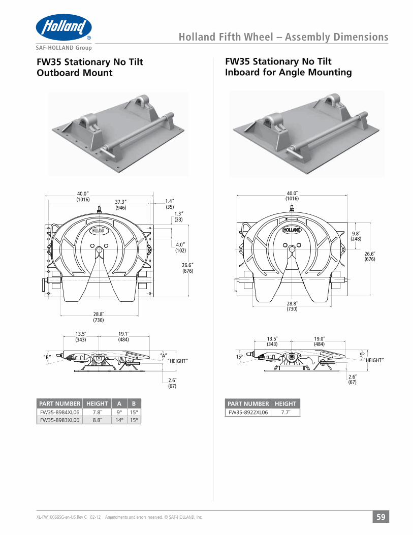
FW35 Stationary No Tilt Outboard Mount
FW35 Stationary No Tilt Inboard for Angle Mounting
Holland Fifth Wheel – Assembly Dimensions
59
“A”“B”
28.8˝(730)
1.3”(33)
26.6”(676)
1.4”(35)
37.3”(946)
4.0”(102)
19.1˝(484)
13.5˝(343)
“HEIGHT”
2.6˝(67)
40.0”(1016)
HOLLAND
40.0˝(1016)
9.8˝(248)
26.6˝(676)
28.8˝(730)
15° 9°
2.6˝(67)
19.0˝(484)
13.5˝(343)
“HEIGHT”
PART NUMBER HEIGHT A B7.8˝ 9º 15º8.8˝ 14º 15º
PART NUMBER HEIGHT7.7˝
XL-FW10066SG-en-US Rev C 02-12 Amendments and errors reserved. © SAF-HOLLAND, Inc.
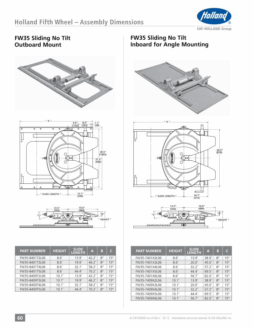
FW35 Sliding No Tilt Outboard Mount
FW35 Sliding No Tilt Inboard for Angle Mounting
Holland Fifth Wheel – Assembly Dimensions
60
“C” “B”
" SLIDE LENGTH "
" HEIGHT "
19.0”(484)
13.5”(343)
(203)
" A "
37.3”(946)
(28)1.1”
39.5”(1003)
(102)8.0”4.0”
15.7”(399) " SLIDE LENGTH "
“B”“C”
(373)14.7”
34.5”(876)
" A "
19.0”(484)
" HEIGHT "
13.5”(343)
PART NUMBER HEIGHT SLIDELENGTH A B C
8.6˝ 13.9˝ 38.9˝ 8° 15°8.6˝ 20.0˝ 45.0˝ 8° 15°8.6˝ 32.2˝ 57.2˝ 8° 15°8.6˝ 44.4˝ 69.5˝ 8° 15°8.6˝ 56.7˝ 82.0˝ 8° 15°10.1˝ 13.9˝ 38.9˝ 8° 15°10.1˝ 20.0˝ 45.0˝ 8° 15°10.1˝ 32.2˝ 57.2˝ 8° 15°10.1˝ 44.4˝ 69.5˝ 8° 15°10.1˝ 56.7˝ 82.0˝ 8° 15°
PART NUMBER HEIGHT SLIDELENGTH A B C
8.6˝ 13.9˝ 42.2˝ 8° 15°8.6˝ 19.9˝ 46.2˝ 8° 15°8.6˝ 32.1˝ 58.2˝ 8° 15°8.6˝ 44.4˝ 70.2˝ 8° 15°10.1˝ 13.9˝ 42.2˝ 8° 15°10.1˝ 19.9˝ 46.2˝ 8° 15°10.1˝ 32.1˝ 58.2˝ 8° 15°10.1˝ 44.4˝ 70.2˝ 8° 15°

XL-FW10066SG-en-US Rev C 02-12 Amendments and errors reserved. © SAF-HOLLAND, Inc.
FW35 Stationary Kompensator Outboard Plate Mount
FW35 Stationary Kompensator Inboard Plate Mount forAngle Mounting
Holland Fifth Wheel – Assembly Dimensions
61
“B” “A” “HEIGHT”
37.3˝(946)
13.5˝(343)
19.0˝(484)
30.0˝(762)
4.0˝(102)
3.0˝(76)
1.4˝(35)
40.0˝(1016)
40
“B”“A”
19.1˝(484)
13.5˝(343)
“HEIGHT”
2.0˝(51)
40.0˝(1016)
28.0˝(711)
PART NUMBER HEIGHT A B9.8˝ 19° 19º11.8˝ 19º 19º12.8˝ 19º 19º
PART NUMBER HEIGHT A B9.8˝ 24° 22º11.8˝ 19º 19º12.8˝ 19º 19º
XL-FW10066SG-en-US Rev C 02-12 Amendments and errors reserved. © SAF-HOLLAND, Inc.
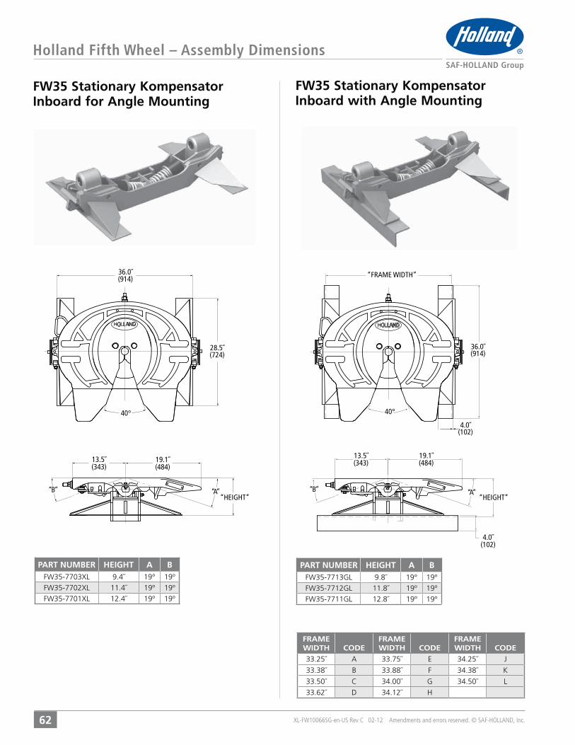
FW35 Stationary Kompensator Inboard for Angle Mounting
FW35 Stationary Kompensator Inboard with Angle Mounting
Holland Fifth Wheel – Assembly Dimensions
62
“B” “A”
36.0˝(914)
28.5˝(724)
19.1˝(484)
13.5˝(343)
“HEIGHT”
40°
“A”“B”
40°
“FRAME WIDTH”
36.0˝(914)
19.1˝(484)
13.5˝(343)
“HEIGHT”
4.0˝(102)
4.0˝(102)
PART NUMBER HEIGHT A B9.4˝ 19° 19º11.4˝ 19º 19º12.4˝ 19º 19º
PART NUMBER HEIGHT A B9.8˝ 19° 19º11.8˝ 19º 19º12.8˝ 19º 19º
FRAMEWIDTH CODE
FRAMEWIDTH CODE
FRAMEWIDTH CODE
33.25˝ A 33.75˝ E 34.25˝ J
33.38˝ B 33.88˝ F 34.38˝ K
33.50˝ C 34.00˝ G 34.50˝ L
33.62˝ D 34.12˝ H
XL-FW10066SG-en-US Rev C 02-12 Amendments and errors reserved. © SAF-HOLLAND, Inc.
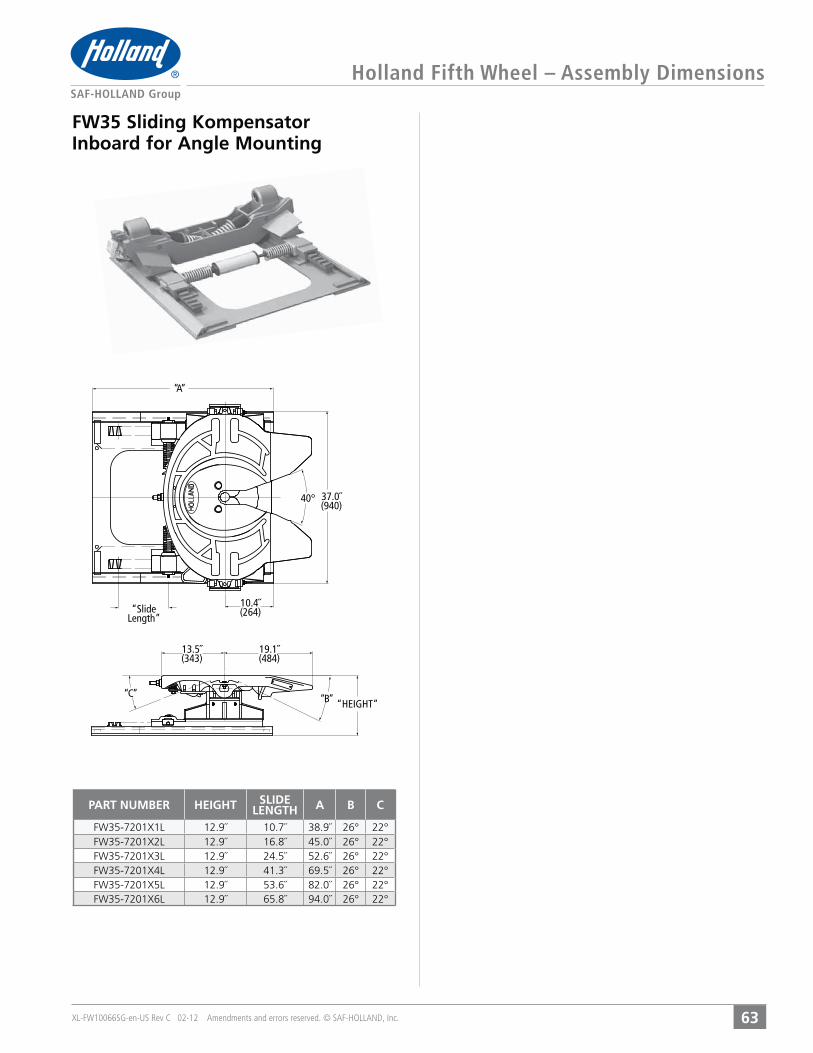
FW35 Sliding Kompensator Inboard for Angle Mounting
Holland Fifth Wheel – Assembly Dimensions
63
40°
“A”
“B”“C”
10.4˝(264)
19.1˝(484)
“HEIGHT”
13.5˝(343)
“Slide Length”
37.0˝(940)
PART NUMBER HEIGHT SLIDELENGTH A B C
12.9˝ 10.7˝ 38.9˝ 26° 22°12.9˝ 16.8˝ 45.0˝ 26° 22°12.9˝ 24.5˝ 52.6˝ 26° 22°12.9˝ 41.3˝ 69.5˝ 26° 22°12.9˝ 53.6˝ 82.0˝ 26° 22°12.9˝ 65.8˝ 94.0˝ 26° 22°

XL-FW10066SG-en-US Rev C 02-12 Amendments and errors reserved. © SAF-HOLLAND, Inc.
FW31 Stationary Foot Mount
FW31 Stationary Integrated Plate Mount
Holland Fifth Wheel – Assembly Dimensions
64
36.8”(935)
39.9”(1013)
16.0”(406)
18.0”(457)
40°
"B" "A""HEIGHT"
19.0”(484)
13.5”(343)
40.0”(1016)
18.5”(470)
1.3”(32)
4.0”(102)
40°
37.3”(946)
"A""B"
19.0”(484)
13.5”(343)
"HEIGHT"
PART NUMBER HEIGHT A B6.0˝ 8° 8º7.0˝ 11º 11º
8.0˝ 14º 14º9.0˝ 17º 17º
PART NUMBER HEIGHT A B6.0˝ 8° 8º7.0˝ 11º 11º
8.0˝ 14º 14º9.0˝ 17º 17º
A flat or corrugated mounting plate is required for foot mount brackets.

XL-FW10066SG-en-US Rev C 02-12 Amendments and errors reserved. © SAF-HOLLAND, Inc.
FW31 Stationary Brackets for Angle Mounting
FW31 Stationary Brackets with Angle Mounting
Holland Fifth Wheel – Assembly Dimensions
65
33.2”(843)
40°
"B" "A""HEIGHT"
19.0”(484)
13.5”(343)
"FRAME WIDTH"
40°4.0”(102)
36.0”(914)
"B" "A"
19.0”(484)
13.5”(343)
"HEIGHT"
4.0”(102)
FRAMEWIDTH CODE
FRAMEWIDTH CODE
FRAMEWIDTH CODE
33.25˝ A 33.75˝ E 34.25˝ J
33.38˝ B 33.88˝ F 34.38˝ K
33.50˝ C 34.00˝ G 34.50˝ L
33.62˝ D 34.12˝ H
PART NUMBER HEIGHT A B5.6˝ 8° 8º6.6˝ 11º 11º
7.6˝ 14º 14º8.6˝ 17º 17º
PART NUMBER HEIGHT A B6.0˝ 8° 8º7.0˝ 11º 11º
8.0˝ 14º 14º9.0˝ 17º 17º

XL-FW10066SG-en-US Rev C 02-12 Amendments and errors reserved. © SAF-HOLLAND, Inc.
FW31 Outboard Sliding Mount
FW31 Inboard Sliding Mount
Holland Fifth Wheel – Assembly Dimensions
66
"SLIDE LENGTH"
40.0”(1016)
37.3”(946)
39.5”(1003)
9.8”(248)
40°
"C" "B"
19.0”(484)
13.5”(343)
"HEIGHT"
"A"
4.0”(102)
"SLIDE LENGTH"
"A"
35.5”(902)
9.8”(248)
"B""C"
19.0”(484)
13.5”(343)
"HEIGHT"
40°
PART NUMBER HEIGHT SLIDELENGTH A B C
7.1˝ 12˝ 31˝ 8° 8°7.1˝ 24˝ 43˝ 8° 8°7.1˝ 36˝ 55˝ 8° 8°7.1˝ 48˝ 67˝ 8° 8°8.1˝ 12˝ 31˝ 12° 10°8.1˝ 24˝ 43˝ 12° 10°8.1˝ 36˝ 55˝ 12° 10°8.1˝ 48˝ 67˝ 12° 10°9.1˝ 12˝ 31˝ 15° 12°9.1˝ 24˝ 43˝ 15° 12°9.1˝ 36˝ 55˝ 15° 12°9.1˝ 48˝ 67˝ 15° 12°
PART NUMBER HEIGHT SLIDELENGTH A B C
7.1˝ 12˝ 31˝ 8° 8°7.1˝ 24˝ 43˝ 8° 8°7.1˝ 36˝ 55˝ 8° 8°7.1˝ 48˝ 67˝ 8° 8°8.1˝ 12˝ 31˝ 12° 10°8.1˝ 24˝ 43˝ 12° 10°8.1˝ 36˝ 55˝ 12° 10°8.1˝ 48˝ 67˝ 12° 10°9.1˝ 12˝ 31˝ 15° 12°9.1˝ 24˝ 43˝ 15° 12°9.1˝ 36˝ 55˝ 15° 12°9.1˝ 48˝ 67˝ 15° 12°
XL-FW10066SG-en-US Rev C 02-12 Amendments and errors reserved. © SAF-HOLLAND, Inc.
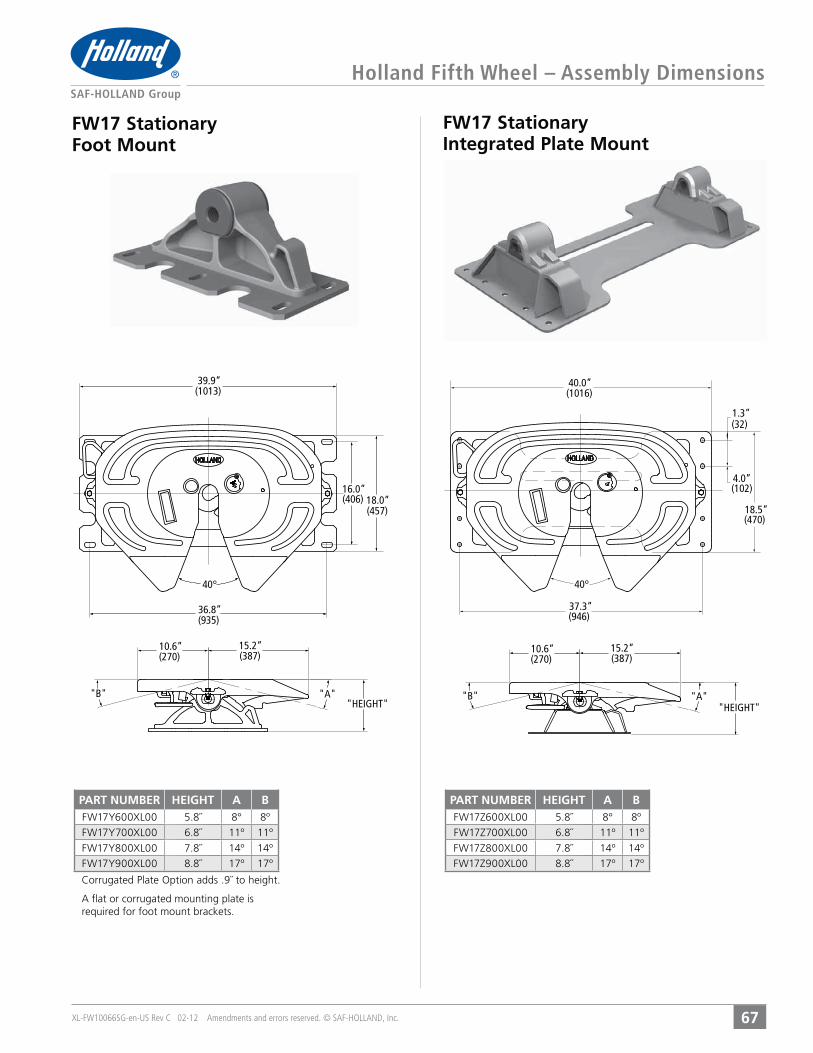
Holland Fifth Wheel – Assembly Dimensions
67
FW17 Stationary Foot Mount
FW17 Stationary Integrated Plate Mount
36.8”(935)
39.9”(1013)
16.0”(406) 18.0”
(457)
40°
"A""B"
15.2”(387)
10.6”(270)
"HEIGHT"
40.0”(1016)
1.3”(32)
4.0”(102)
18.5”(470)
37.3”(946)
40°
"A""B"
15.2”(387)
10.6”(270)
"HEIGHT"
PART NUMBER HEIGHT A B5.8˝ 8° 8º6.8˝ 11º 11º
7.8˝ 14º 14º8.8˝ 17º 17º
PART NUMBER HEIGHT A B5.8˝ 8° 8º6.8˝ 11º 11º
7.8˝ 14º 14º8.8˝ 17º 17º
A flat or corrugated mounting plate is required for foot mount brackets.
XL-FW10066SG-en-US Rev C 02-12 Amendments and errors reserved. © SAF-HOLLAND, Inc.
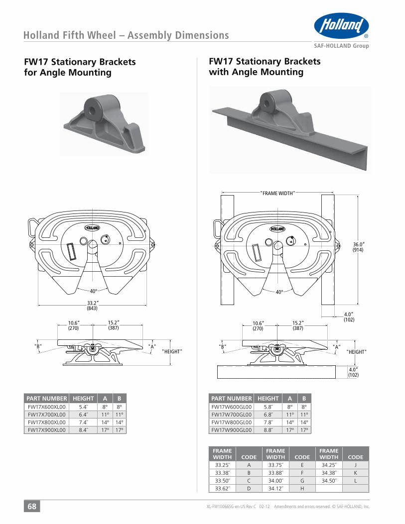
Holland Fifth Wheel – Assembly Dimensions
68
FW17 Stationary Brackets for Angle Mounting
FW17 Stationary Brackets with Angle Mounting
33.2”(843)
40°
"A""B"
15.2”(387)
10.6”(270)
"HEIGHT""A""B"
15.2”
4.0”
(387)10.6”(270)
"HEIGHT"
"FRAME WIDTH"
36.0”(914)
(102)
40°
4.0”(102)
FRAMEWIDTH CODE
FRAMEWIDTH CODE
FRAMEWIDTH CODE
33.25˝ A 33.75˝ E 34.25˝ J
33.38˝ B 33.88˝ F 34.38˝ K
33.50˝ C 34.00˝ G 34.50˝ L
33.62˝ D 34.12˝ H
PART NUMBER HEIGHT A B5.4˝ 8° 8º6.4˝ 11º 11º
7.4˝ 14º 14º8.4˝ 17º 17º
PART NUMBER HEIGHT A B5.8˝ 8° 8º6.8˝ 11º 11º
7.8˝ 14º 14º8.8˝ 17º 17º

XL-FW10066SG-en-US Rev C 02-12 Amendments and errors reserved. © SAF-HOLLAND, Inc.
Holland Fifth Wheel – Assembly Dimensions
69
FW17 Outboard Sliding Mount
FW17 Inboard Sliding Mount
"SLIDE LENGTH"
"A"
35.5”(902)
9.8”(248)
40°
"B""C""HEIGHT"
15.2”(387)
10.6”(270)
"SLIDE LENGTH" 9.8”(248)
40.0”(1016)
40°
37.3”(946)
39.5”(1003)
"B""C""HEIGHT"
15.2”(387)
10.6”(270)
"A"
4.0”(102)
PART NUMBER HEIGHT SLIDELENGTH A B C
6.8˝ 12˝ 31˝ 8° 8°6.8˝ 24˝ 43˝ 8° 8°6.8˝ 36˝ 55˝ 8° 8°6.8˝ 48˝ 67˝ 8° 8°7.8˝ 12˝ 31˝ 12° 10°7.8˝ 24˝ 43˝ 12° 10°7.8˝ 36˝ 55˝ 12° 10°7.8˝ 48˝ 67˝ 12° 10°8.8˝ 12˝ 31˝ 15° 12°8.8˝ 24˝ 43˝ 15° 12°8.8˝ 36˝ 55˝ 15° 12°8.8˝ 48˝ 67˝ 15° 12°
PART NUMBER HEIGHT SLIDELENGTH A B C
6.8˝ 12˝ 31˝ 8° 8°6.8˝ 24˝ 43˝ 8° 8°6.8˝ 36˝ 55˝ 8° 8°6.8˝ 48˝ 67˝ 8° 8°7.8˝ 12˝ 31˝ 12° 10°7.8˝ 24˝ 43˝ 12° 10°7.8˝ 36˝ 55˝ 12° 10°7.8˝ 48˝ 67˝ 12° 10°8.8˝ 12˝ 31˝ 15° 12°8.8˝ 24˝ 43˝ 15° 12°8.8˝ 36˝ 55˝ 15° 12°8.8˝ 48˝ 67˝ 15° 12°
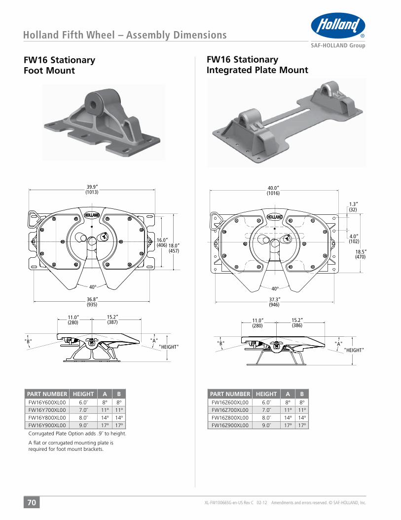
Holland Fifth Wheel – Assembly Dimensions
70 XL-FW10066SG-en-US Rev C 02-12 Amendments and errors reserved. © SAF-HOLLAND, Inc.
FW16 Stationary Foot Mount
FW16 Stationary Integrated Plate Mount
36.8”(935)
39.9”(1013)
16.0”(406) 18.0”
(457)
40°
"A""B"
15.2”(387)
11.0”(280)
"HEIGHT"
40.0”(1016)
1.3”(32)
4.0”(102)
18.5”(470)
37.3”(946)
40°
"A""B"
15.2”(386)
11.0”(280)
"HEIGHT"
PART NUMBER HEIGHT A B6.0˝ 8° 8º7.0˝ 11º 11º
8.0˝ 14º 14º9.0˝ 17º 17º
PART NUMBER HEIGHT A B6.0˝ 8° 8º7.0˝ 11º 11º
8.0˝ 14º 14º9.0˝ 17º 17º
A flat or corrugated mounting plate is required for foot mount brackets.

Holland Fifth Wheel – Assembly Dimensions
71XL-FW10066SG-en-US Rev C 02-12 Amendments and errors reserved. © SAF-HOLLAND, Inc.
FW16 Stationary Brackets for Angle Mounting
FW16 Stationary Brackets with Angle Mounting
33.2”
16.2˝ (411)
(843)
40°
"A""B"
15.2”(387)
10.6”(280)
"HEIGHT""A""B"
15.2”
4.0”33.2˝ (843)
2.8˝ (71)
(387)11.0”(280)
"HEIGHT"
"FRAME WIDTH"
36.0”16.2˝(411) (914)
(102)
40°
4 0”
FRAMEWIDTH CODE
FRAMEWIDTH CODE
FRAMEWIDTH CODE
33.25˝ A 33.75˝ E 34.25˝ J
33.38˝ B 33.88˝ F 34.38˝ K
33.50˝ C 34.00˝ G 34.50˝ L
33.62˝ D 34.12˝ H
PART NUMBER HEIGHT A B5.6˝ 8° 8º6.6˝ 11º 11º
7.6˝ 14º 14º8.6 17º 17º
PART NUMBER HEIGHT A B6.0˝ 8° 8º7.0˝ 11º 11º
8.0˝ 14º 14º9.0˝ 17º 17º

Holland Fifth Wheel – Assembly Dimensions
72 XL-FW10066SG-en-US Rev C 02-12 Amendments and errors reserved. © SAF-HOLLAND, Inc.
FW16 Outboard Sliding Mount
FW16 Inboard Sliding Mount
"SLIDE LENGTH"
"A"
35.5”(902)
9.7”(248)
40°
"B""C""HEIGHT"
15.2”(387)
11.1”(280)
"SLIDE LENGTH" 9.8”(248)
40.0”(1016)
40°
37.3”(946)
39.5”(1003)
"B""C""HEIGHT"
15.2”(387)
10.6”(270)
"A"
4.0”(102)
PART NUMBER HEIGHT SLIDELENGTH A B C
7.1˝ 12˝ 31˝ 8° 8°7.1˝ 24˝ 43˝ 8° 8°7.1˝ 36˝ 55˝ 8° 8°7.1˝ 48˝ 67˝ 8° 8°8.1˝ 12˝ 31˝ 12° 10°8.1˝ 24˝ 43˝ 12° 10°8.1˝ 36˝ 55˝ 12° 10°8.1˝ 48˝ 67˝ 12° 10°9.1˝ 12˝ 31˝ 15° 12°9.1˝ 24˝ 43˝ 15° 12°9.1˝ 36˝ 55˝ 15° 12°9.1˝ 48˝ 67˝ 15° 12°
PART NUMBER HEIGHT SLIDELENGTH A B C
7.1˝ 12˝ 31˝ 8° 8°7.1˝ 24˝ 43˝ 8° 8°7.1˝ 36˝ 55˝ 8° 8°7.1˝ 48˝ 67˝ 8° 8°8.1˝ 12˝ 31˝ 12° 10°8.1˝ 24˝ 43˝ 12° 10°8.1˝ 36˝ 55˝ 12° 10°8.1˝ 48˝ 67˝ 12° 10°9.1˝ 12˝ 31˝ 15° 12°9.1˝ 24˝ 43˝ 15° 12°9.1˝ 36˝ 55˝ 15° 12°9.1˝ 48˝ 67˝ 15° 12°
Holland Fifth Wheel – Assembly Dimensions
73XL-FW10066SG-en-US Rev C 02-12 Amendments and errors reserved. © SAF-HOLLAND, Inc.
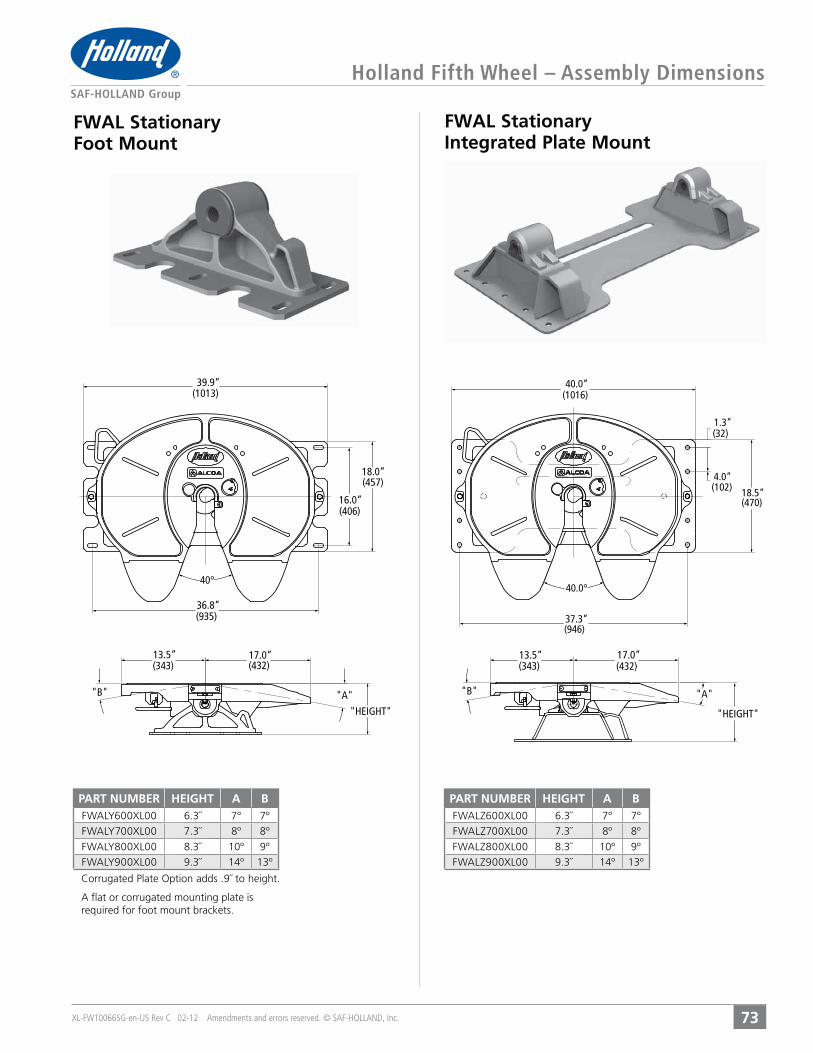
FWAL Stationary Foot Mount
FWAL Stationary Integrated Plate Mount
36.8”(935)
39.9”(1013)
16.0”(406)
18.0”(457)
40°
"A""B"
17.0”(432)
13.5”(343)
"HEIGHT"
40.0”(1016)
1.3”(32)
4.0”(102) 18.5”
(470)
37.3”(946)
40.0°
"B" "A"
17.0”(432)
13.5”(343)
"HEIGHT"
PART NUMBER HEIGHT A B6.3˝ 7° 7º7.3˝ 8º 8º
8.3˝ 10º 9º9.3˝ 14º 13º
PART NUMBER HEIGHT A B6.3˝ 7° 7º7.3˝ 8º 8º
8.3˝ 10º 9º9.3˝ 14º 13º
A flat or corrugated mounting plate is required for foot mount brackets.
XL-FW10066SG-en-US Rev C 02-12 Amendments and errors reserved. © SAF-HOLLAND, Inc.
Holland Fifth Wheel – Assembly Dimensions
74
FWAL Stationary Brackets for Angle Mounting
FWAL Stationary Brackets with Angle Mounting
33.2”(843)
40.0°
"B" "A"
17.0”(432)
13.5”(343)
"HEIGHT"
FRAME WIDTH
36.0”(914)
4.0”(102)
40°
"A""B"
17.0”(432)
13.5”(343)
"HEIGHT"
4.0”(102)
FRAMEWIDTH CODE
FRAMEWIDTH CODE
FRAMEWIDTH CODE
33.25˝ A 33.75˝ E 34.25˝ J
33.38˝ B 33.88˝ F 34.38˝ K
33.50˝ C 34.00˝ G 34.50˝ L
33.62˝ D 34.12˝ H
PART NUMBER HEIGHT A B5.9˝ 7° 7º6.9˝ 8º 8º
7.9˝ 10º 9º8.9˝ 14º 13º
PART NUMBER HEIGHT A B6.3˝ 7° 7º7.3˝ 8º 8º
8.3˝ 10º 9º9.3˝ 14º 13º

XL-FW10066SG-en-US Rev C 02-12 Amendments and errors reserved. © SAF-HOLLAND, Inc.
Holland Fifth Wheel – Assembly Dimensions
75
FWAL Outboard Sliding Mount
FWAL Inboard Sliding Mount
"SLIDE LENGTH"
37.3”(946)
39.5”(1003)
40.0”(1016)
9.8”(248)
40°
"B""C"
17.0”(432)
13.5”(343)
"HEIGHT
4.0”(102)
"A"
“SLIDE LENGTH” 9.8”(248)
35.5”(902)
"A"
40°
"C" "B"
17.0”(432)
13.5”(343)
"HEIGHT"
PART NUMBER HEIGHT SLIDELENGTH A B C
7.3˝ 12˝ 31˝ 8° 9°7.3˝ 24˝ 43˝ 8° 9°7.3˝ 36˝ 55˝ 8° 9°7.3˝ 48˝ 67˝ 8° 9°8.3˝ 12˝ 31˝ 13° 18°8.3˝ 24˝ 43˝ 13° 18°8.3˝ 36˝ 55˝ 13° 18°8.3˝ 48˝ 67˝ 13° 18°9.3˝ 12˝ 31˝ 15° 20°9.3˝ 24˝ 43˝ 15° 20°9.3˝ 36˝ 55˝ 15° 20°9.3˝ 48˝ 67˝ 15° 20°
PART NUMBER HEIGHT SLIDELENGTH A B C
7.3˝ 12˝ 31˝ 8° 9°7.3˝ 24˝ 43˝ 8° 9°7.3˝ 36˝ 55˝ 8° 9°7.3˝ 48˝ 67˝ 8° 9°8.3˝ 12˝ 31˝ 13° 18°8.3˝ 24˝ 43˝ 13° 18°8.3˝ 36˝ 55˝ 13° 18°8.3˝ 48˝ 67˝ 13° 18°9.3˝ 12˝ 31˝ 15° 20°9.3˝ 24˝ 43˝ 15° 20°9.3˝ 36˝ 55˝ 15° 20°9.3˝ 48˝ 67˝ 15° 20°

XL-FW10066SG-en-US Rev C 02-12 Amendments and errors reserved. © SAF-HOLLAND, Inc.
FWS1 Stationary Foot Mount
FWS1 Stationary Integrated Plate Mount
Holland Fifth Wheel – Assembly Dimensions
76
11.2˝(284)
36.8˝(935)
40º
16.0˝(406)
10.8˝(457)
39.9˝(1013)
14.5˝(368)
“B” “A”“HEIGHT”
11.2˝(284)
40º
4.0˝(102)
1.3˝(32)
18.5˝(470)
40.0˝(1016)
14.5˝(368)
“B” “A”“HEIGHT”
37.3˝(946.0)
PART NUMBER HEIGHT A B6.1˝ 11° 7º7.1˝ 14º 15º
8.1˝ 17º 20º9.1˝ 20º 24º
PART NUMBER HEIGHT A B6.1˝ 11° 7º7.1˝ 14º 15º
8.1˝ 17º 20º9.1˝ 20º 24º
A flat or corrugated mounting plate is required for foot mount brackets.
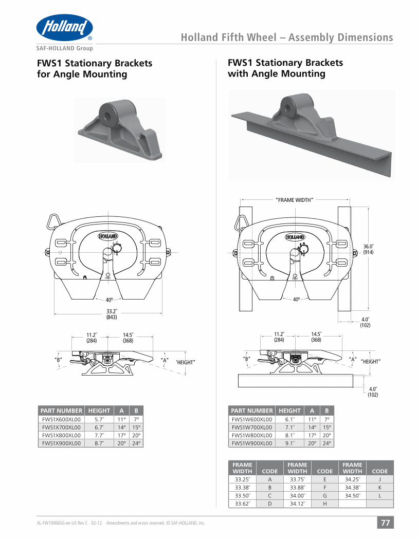
XL-FW10066SG-en-US Rev C 02-12 Amendments and errors reserved. © SAF-HOLLAND, Inc.
Holland Fifth Wheel – Assembly Dimensions
77
FWS1 Stationary Brackets for Angle Mounting
FWS1 Stationary Brackets with Angle Mounting
11.2˝(284)
40º
36.0˝(914)
4.0˝(102)
4.0˝(102)
“FRAME WIDTH”
14.5˝(368)
“B” “A” “HEIGHT”
11.2˝(284)
33.2˝(843)
40º
14.5˝(368)
“B” “A” ‘HEIGHT”
FRAMEWIDTH CODE
FRAMEWIDTH CODE
FRAMEWIDTH CODE
33.25˝ A 33.75˝ E 34.25˝ J
33.38˝ B 33.88˝ F 34.38˝ K
33.50˝ C 34.00˝ G 34.50˝ L
33.62˝ D 34.12˝ H
PART NUMBER HEIGHT A B5.7˝ 11° 7º6.7˝ 14º 15º
7.7˝ 17º 20º8.7˝ 20º 24º
PART NUMBER HEIGHT A B6.1˝ 11° 7º7.1˝ 14º 15º
8.1˝ 17º 20º9.1˝ 20º 24º

XL-FW10066SG-en-US Rev C 02-12 Amendments and errors reserved. © SAF-HOLLAND, Inc.
FWS1 Outboard Sliding Mount
FWS1 Inboard Sliding Mount
Holland Fifth Wheel – Assembly Dimensions
78
40º
35.5˝(902)
“SLIDE LENGTH” 9.8˝248
14.5˝(368)
11.2˝(284)
“A”
“B”“HEIGHT
“C”
11.2˝(284)
9.8˝(248)
“SLIDE LENGTH”
40º
37.3˝(946)
39.5˝(1003)
“A”
40.0˝(1016)
4.0˝(102)
14.5˝(368)
“C” “B”“HEIGH
PART NUMBER HEIGHT SLIDELENGTH A B C
7.1˝ 12˝ 31˝ 11° 6°7.1˝ 24˝ 43˝ 11° 6°7.1˝ 36˝ 55˝ 11° 6°7.1˝ 48˝ 67˝ 11° 6°8.1˝ 12˝ 31˝ 15° 12°8.1˝ 24˝ 43˝ 15° 12°8.1˝ 36˝ 55˝ 15° 12°8.1˝ 48˝ 67˝ 15° 12°9.1˝ 12˝ 31˝ 18° 19°9.1˝ 24˝ 43˝ 18° 19°9.1˝ 36˝ 55˝ 18° 19°9.1˝ 48˝ 67˝ 18° 19°
PART NUMBER HEIGHT SLIDELENGTH A B C
7.1˝ 12˝ 31˝ 11° 6°7.1˝ 24˝ 43˝ 11° 6°7.1˝ 36˝ 55˝ 11° 6°7.1˝ 48˝ 67˝ 11° 6°8.1˝ 12˝ 31˝ 15° 12°8.1˝ 24˝ 43˝ 15° 12°8.1˝ 36˝ 55˝ 15° 12°8.1˝ 48˝ 67˝ 15° 12°9.1˝ 12˝ 31˝ 18° 19°9.1˝ 24˝ 43˝ 18° 19°9.1˝ 36˝ 55˝ 18° 19°9.1˝ 48˝ 67˝ 18° 19°
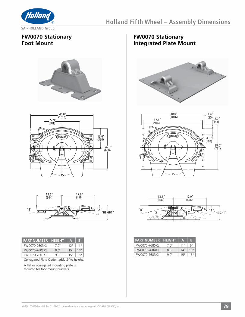
XL-FW10066SG-en-US Rev C 02-12 Amendments and errors reserved. © SAF-HOLLAND, Inc.
Holland Fifth Wheel – Assembly Dimensions
79
FW0070 Stationary Foot Mount
FW0070 Stationary Integrated Plate Mount
(1016)40.0”
(581)22.9”
(660)26.0”
(330)13.0”
45˚
"A""B"
(456)17.9”
(344)13.6”
"HEIGHT""A""B"
(1016)40.0”
(946)37.3”
(35)1.4”
(51)2.0”
(102)4.0”
(711)28.0”
"HEIGHT"
(456)17.9”
(344)13.6”
45˚
PART NUMBER HEIGHT A B7.0˝ 12° 11º8.0˝ 15º 15º9.0˝ 15º 15º
PART NUMBER HEIGHT A B7.0˝ 11° 6º8.0˝ 14º 15º9.0˝ 15º 15º
A flat or corrugated mounting plate is required for foot mount brackets.

XL-FW10066SG-en-US Rev C 02-12 Amendments and errors reserved. © SAF-HOLLAND, Inc.
Holland Fifth Wheel – Assembly Dimensions
80
FW0070 Stationary Brackets for Angle Mounting
FW0070 Stationary Brackets with Angle Mounting
"A""B"
(456)17.9”
(344)13.6”
(861)33.9”
(356)14.0”
"HEIGHT"
45˚
"FRAME WIDTH"
(457)18.0”
(914)36.0”
45˚
"A""B"
(456)17.9”
(344)13.6”
"HEIGHT"
4.0˝(102)
FRAMEWIDTH CODE
FRAMEWIDTH CODE
FRAMEWIDTH CODE
33.25˝ A 33.75˝ E 34.25˝ J
33.38˝ B 33.88˝ F 34.38˝ K
33.50˝ C 34.00˝ G 34.50˝ L
33.62˝ D 34.12˝ H
PART NUMBER HEIGHT A B6.5˝ 12° 11º7.5˝ 15º 15º8.5˝ 15º 15º
PART NUMBER HEIGHT A B6.0˝ 8° 5º7.0˝ 12º 11º
8.0˝ 15º 15º9.0˝ 15º 15º
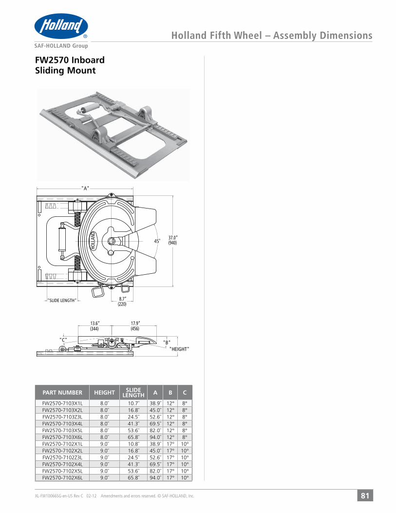
XL-FW10066SG-en-US Rev C 02-12 Amendments and errors reserved. © SAF-HOLLAND, Inc.
Holland Fifth Wheel – Assembly Dimensions
81
FW2570 Inboard Sliding Mount
45˚
"C" "B"
"A"
(456)17.9”
(344)13.6”
"SLIDE LENGTH"(220)8.7”
(940)37.0”
"HEIGHT"
HOLL
AND
PART NUMBER HEIGHT SLIDELENGTH A B C
8.0˝ 10.7˝ 38.9˝ 12° 8°8.0˝ 16.8˝ 45.0˝ 12° 8°8.0˝ 24.5˝ 52.6˝ 12° 8°8.0˝ 41.3˝ 69.5˝ 12° 8°8.0˝ 53.6˝ 82.0˝ 12° 8°8.0˝ 65.8˝ 94.0˝ 12° 8°9.0˝ 10.8˝ 38.9˝ 17° 10°9.0˝ 16.8˝ 45.0˝ 17° 10°9.0˝ 24.5˝ 52.6˝ 17° 10°9.0˝ 41.3˝ 69.5˝ 17° 10°9.0˝ 53.6˝ 82.0˝ 17° 10°9.0˝ 65.8˝ 94.0˝ 17° 10°

XL-FW10066SG-en-US Rev C 02-12 Amendments and errors reserved. © SAF-HOLLAND, Inc.
Holland Fifth Wheel – Assembly Dimensions
82
FW7040 Stationary Kompensator Outboard Mount
FW7090 Sliding Kompensator for Angle Mounting
HOLL
AND
45˚ 37.0˝(940)
10.4(264)
17.9˝(456)
13.6”(344)
“A”
“C” “B”
“HEIGHT”
“SLIDE LENGTH”
HOLLAND
46°
37.3(946)
“B”
40.0˝(1016)
4.0˝(102)
1.4˝(35) 2.0˝
(51)
17.9˝(456)
“HEIGHT”
13.6˝(344)
36.0˝(914)
“A”
PART NUMBER HEIGHT A B9.9˝ 15° 15º11.9˝ 19º 15º12.9˝ 15º 15º
PART NUMBER HEIGHT SLIDELENGTH A B C
12.9˝ 10.7˝ 38.9˝ 15° 15°12.9˝ 16.8˝ 45.0˝ 15° 15°12.9˝ 24.5˝ 52.6˝ 15° 15°12.9˝ 41.3˝ 69.5˝ 15° 15°12.9˝ 53.6˝ 82.0˝ 15° 15°12.9˝ 65.8˝ 94.0˝ 15° 15°
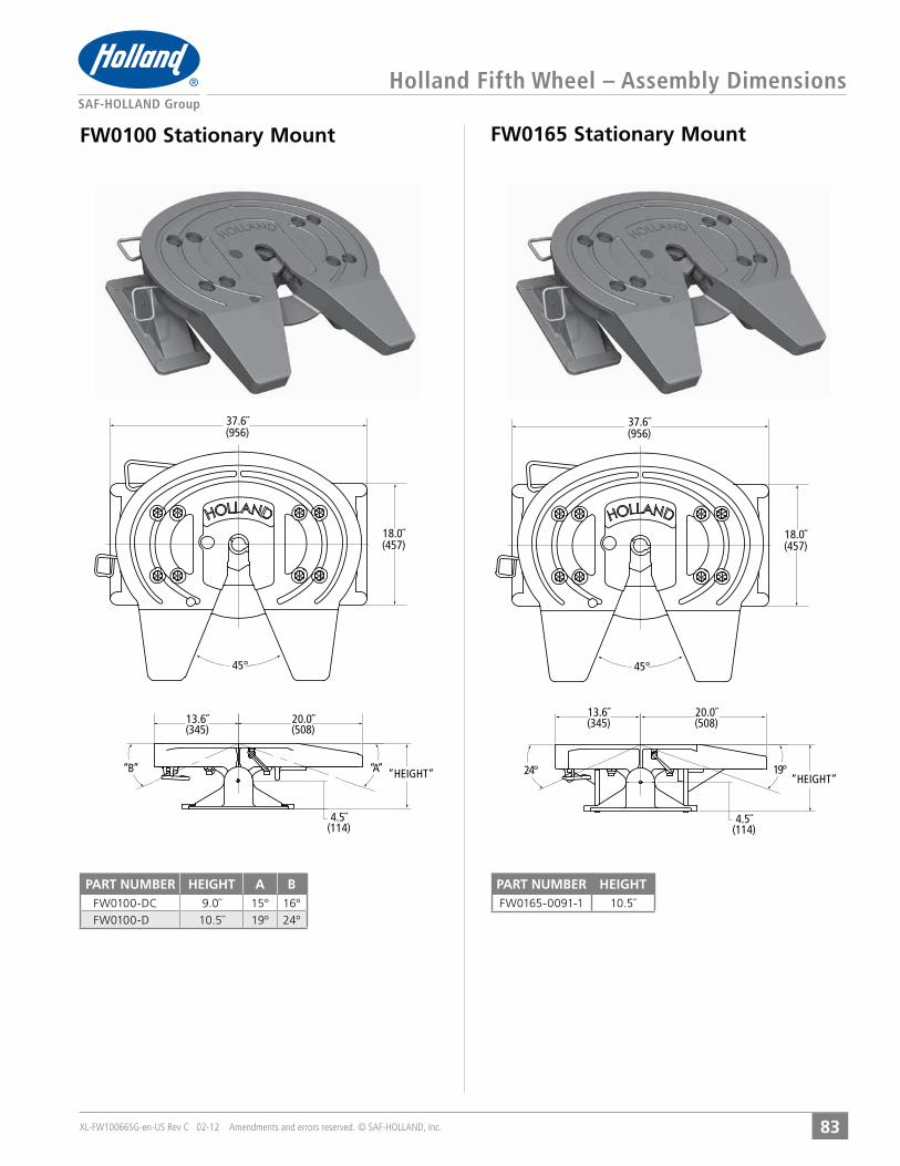
XL-FW10066SG-en-US Rev C 02-12 Amendments and errors reserved. © SAF-HOLLAND, Inc.
Holland Fifth Wheel – Assembly Dimensions
83
FW0100 Stationary Mount FW0165 Stationary Mount
37.6˝(956)
18.0˝(457)
45°
“B” “A”
13.6˝(345)
20.0˝(508)
4.5˝(114)
“HEIGHT” 24° 19°
13.6˝(345)
20.0˝(508)
4.5˝(114)
“HEIGHT”
37.6˝(956)
18.0˝(457)
45°
PART NUMBER HEIGHT A B9.0˝ 15° 16º10.5˝ 19º 24º
PART NUMBER HEIGHTFW0165-0091-1 10.5˝

XL-FW10066SG-en-US Rev C 02-12 Amendments and errors reserved. © SAF-HOLLAND, Inc.84
Holland Fifth Wheel – Assembly Dimensions
FW2080 Stationary Mount
L
40.0˝(1016)
38.0˝(965) 27.4˝
(695)
17.0˝(432)
19.0˝(483)
13.6˝(344)
20.0˝(508)
45˚
“HEIGHT”
PART NUMBER HEIGHT13.6˝

GLOSSARY
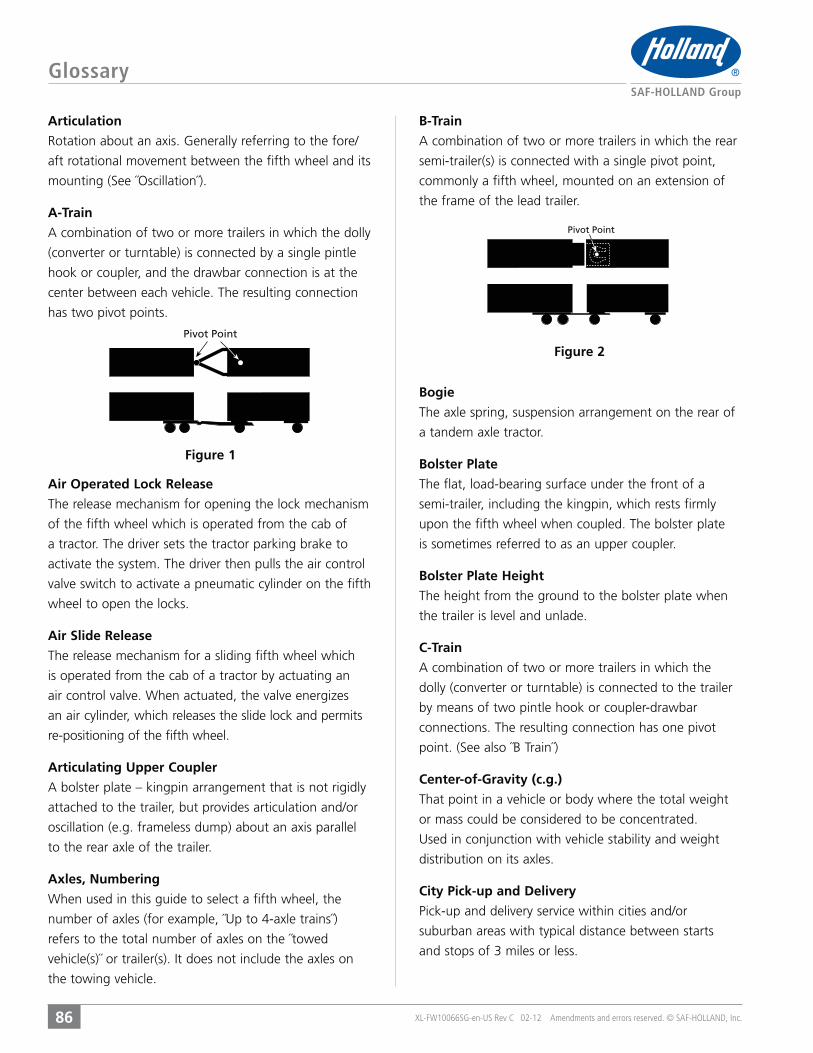
Glossary
86
Articulation
aft rotational movement between the fifth wheel and its
A-Train
A combination of two or more trailers in which the dolly
(converter or turntable) is connected by a single pintle
hook or coupler, and the drawbar connection is at the
center between each vehicle. The resulting connection
has two pivot points.
Air Operated Lock Release
The release mechanism for opening the lock mechanism
of the fifth wheel which is operated from the cab of
a tractor. The driver sets the tractor parking brake to
activate the system. The driver then pulls the air control
valve switch to activate a pneumatic cylinder on the fifth
wheel to open the locks.
Air Slide Release
The release mechanism for a sliding fifth wheel which
is operated from the cab of a tractor by actuating an
an air cylinder, which releases the slide lock and permits
re-positioning of the fifth wheel.
Articulating Upper Coupler
A bolster plate – kingpin arrangement that is not rigidly
attached to the trailer, but provides articulation and/or
oscillation (e.g. frameless dump) about an axis parallel
to the rear axle of the trailer.
Axles, Numbering
When used in this guide to select a fifth wheel, the
number of axles (for example, ˝Up to 4-axle trains˝)
refers to the total number of axles on the ˝towed
the towing vehicle.
B-Train
A combination of two or more trailers in which the rear
semi-trailer(s) is connected with a single pivot point,
commonly a fifth wheel, mounted on an extension of
the frame of the lead trailer.
Bogie
The axle spring, suspension arrangement on the rear of
a tandem axle tractor.
Bolster Plate
The flat, load-bearing surface under the front of a
semi-trailer, including the kingpin, which rests firmly
upon the fifth wheel when coupled. The bolster plate
is sometimes referred to as an upper coupler.
Bolster Plate Height
The height from the ground to the bolster plate when
the trailer is level and unlade.
C-Train
A combination of two or more trailers in which the
dolly (converter or turntable) is connected to the trailer
by means of two pintle hook or coupler-drawbar
connections. The resulting connection has one pivot
Center-of-Gravity (c.g.)
That point in a vehicle or body where the total weight
or mass could be considered to be concentrated.
distribution on its axles.
City Pick-up and Delivery
suburban areas with typical distance between starts
and stops of 3 miles or less.
Pivot Point
Figure 1
Pivot Point
Figure 2
XL-FW10066SG-en-US Rev C 02-12 Amendments and errors reserved. © SAF-HOLLAND, Inc.

Glossary
87
Converter Dolly
An axle, frame, drawbar and fifth wheel arrangement
that converts a semi-trailer into a full trailer.
Drawbar Capacity
safely applied to a coupling device.
Electronic Lock Indicator (ELI®)
that monitors the coupling process from inside the
cab. Magnetic proximity sensors located on the fifth
wheel top plate senses fifth wheel and kingpin locking
sequence, relaying the data to the driver through an
icon based display in the cab.
Extra Capacity
Generally refers to a coupling device which has strength
capability greater than standard.
Fifth Wheel Height
The distance from the ground to the top of the fifth
wheel when it is level and parallel with the ground.
the top of the fifth wheel. The latter definition applies
to data given in fifth wheel literature.
Fifth Wheel Top Plate
The portion of the fifth wheel assembly that contacts
the trailer bolster plate and houses the locking
mechanism that connects to the kingpin.
Frame Width
The measurement across the
outside of the frame rails of a
tractor, truck or trailer.
Full Trailer
A trailer which does not transfer load to the towing
or steerable running gear assembly at the front of
the trailer.
Fully Oscillating Fifth Wheel
Generally refers to a fifth wheel type with fore/aft and
Towed Weight
The sum of the weight of an empty trailer(s) and
its payload.
General Over-the-Road Use
When used in this guide means, a fifth wheel
that is designed for multiple standard duty
highway applications.
ILS
Inboard Angle Mount
mounting angle sits on
the tractor frame.
Kingpin
The pin mounted through the center of the trailer
upper coupler (bolster plate) that mates with the
fifth wheel locks securing the trailer to the fifth wheel.
The configuration is controlled by industry standards.
Kompensator® Mounting Base
A mounting base designed to relieve some of the
torque and twist that is generated by some trailer
designs, thereby reducing or eliminating trailer frame
cracks. Tractor tandem tire life is also greatly increased
due to improved traction. The primary application for ® mounted fifth wheel is for tankers in
which the c.g. does not exceed 44 inches above the top
surface of the fifth wheel.
LowLube
A fifth wheel with recesses cast into the top plate into
which lube free inserts are attached to eliminate the
use of top plate grease. Also includes lube free inserts
between top plate and brackets to eliminate lubrication.
Mounting Bracket
That portion of the fifth wheel assembly that connects
the fifth wheel top plate to the tractor frame or fifth
wheel mounting system.
FrameWidth
Figure 3
XL-FW10066SG-en-US Rev C 02-12 Amendments and errors reserved. © SAF-HOLLAND, Inc.
Figure 4
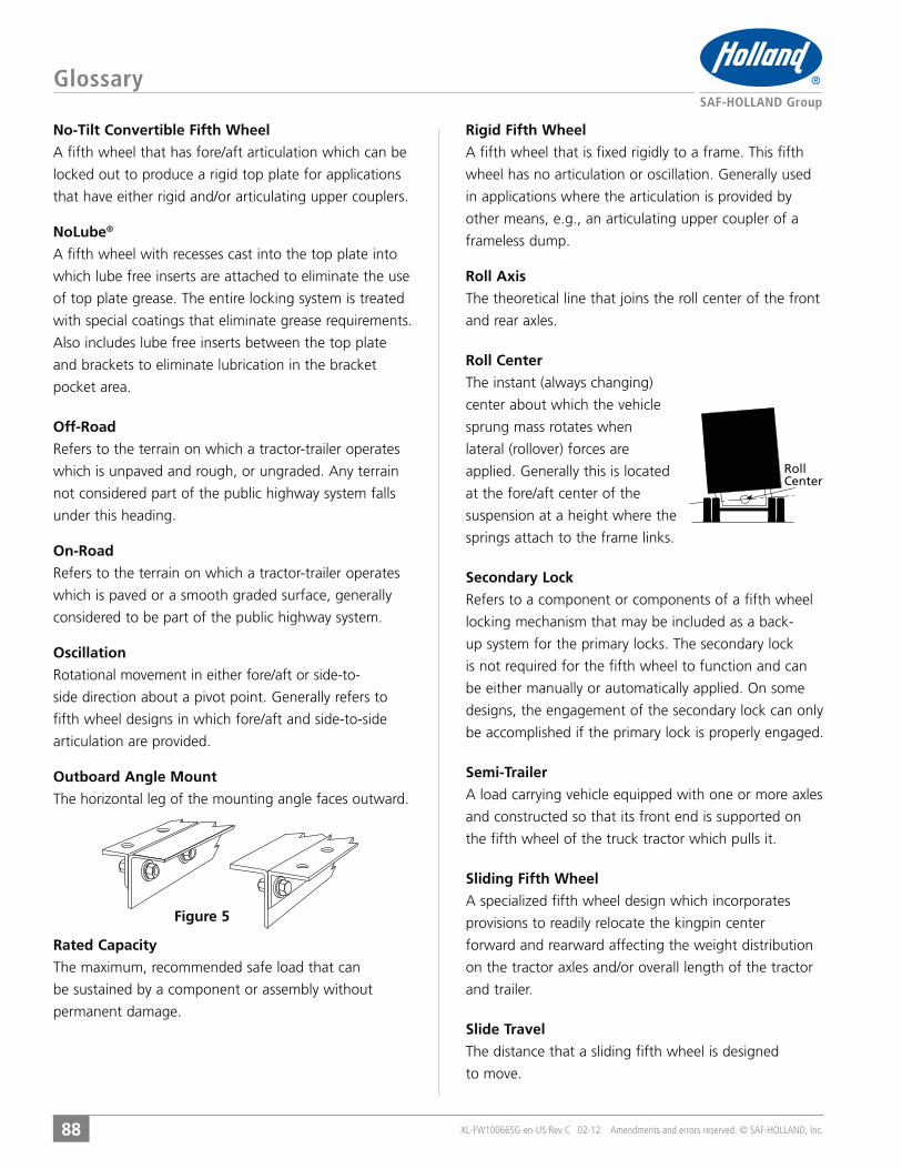
Glossary
88
No-Tilt Convertible Fifth Wheel
A fifth wheel that has fore/aft articulation which can be
locked out to produce a rigid top plate for applications
that have either rigid and/or articulating upper couplers.
NoLube®
A fifth wheel with recesses cast into the top plate into
which lube free inserts are attached to eliminate the use
of top plate grease. The entire locking system is treated
with special coatings that eliminate grease requirements.
Also includes lube free inserts between the top plate
and brackets to eliminate lubrication in the bracket
pocket area.
Off-Road
which is unpaved and rough, or ungraded. Any terrain
not considered part of the public highway system falls
under this heading.
On-Road
which is paved or a smooth graded surface, generally
considered to be part of the public highway system.
Oscillation
side direction about a pivot point. Generally refers to
fifth wheel designs in which fore/aft and side-to-side
articulation are provided.
Outboard Angle Mount
Figure 5
Rated Capacity
The maximum, recommended safe load that can
be sustained by a component or assembly without
permanent damage.
Rigid Fifth Wheel
A fifth wheel that is fixed rigidly to a frame. This fifth
wheel has no articulation or oscillation. Generally used
in applications where the articulation is provided by
other means, e.g., an articulating upper coupler of a
frameless dump.
Roll Axis
and rear axles.
Roll Center
The instant (always changing)
center about which the vehicle
sprung mass rotates when
lateral (rollover) forces are
applied. Generally this is located
at the fore/aft center of the
suspension at a height where the
springs attach to the frame links.
Secondary Lock
locking mechanism that may be included as a back-
up system for the primary locks. The secondary lock
is not required for the fifth wheel to function and can
designs, the engagement of the secondary lock can only
be accomplished if the primary lock is properly engaged.
Semi-Trailer
A load carrying vehicle equipped with one or more axles
and constructed so that its front end is supported on
the fifth wheel of the truck tractor which pulls it.
Sliding Fifth Wheel
provisions to readily relocate the kingpin center
forward and rearward affecting the weight distribution
on the tractor axles and/or overall length of the tractor
and trailer.
Slide Travel
The distance that a sliding fifth wheel is designed
to move.
RollCenter
XL-FW10066SG-en-US Rev C 02-12 Amendments and errors reserved. © SAF-HOLLAND, Inc.
Glossary
89
Stability
A relative measure of the handling characteristics which
provide the desired and safe operation of the vehicle
during various maneuvers.
Stationary Fifth Wheel
A fifth wheel whose location on the tractor frame is
fixed once it is installed.
Tilt Stop
A block or formed plate welded to a fifth wheel
mounting bracket that limits the rearward articulation
of the fifth wheel. Tilt stops are often used to keep the
fifth wheel from resting on or damaging the tractor
frame rails.
TTMA
Truck Trailer Manufacturers Association
TVW (Towed Vehicle Weight)
Total weight of towed vehicles.
Torque and Twist
Generally refers to the forces developed in the trailer
and/or tractor frame that are transmitted through the
fifth wheel when a rigid trailer (e.g. a tanker) is required
to negotiate bumps (i.e. street curbs, etc.).
Torsional Rigidity
to twisting forces.
Universal Fifth Wheel
Upper Coupler
Vertical Load Capacity
The maximum, recommended vertical force (down) than
can be safely applied to a coupling device.
XL-FW10066SG-en-US Rev C 02-12 Amendments and errors reserved. © SAF-HOLLAND, Inc.

Notes
90 XL-FW10066SG-en-US Rev C 02-12 Amendments and errors reserved. © SAF-HOLLAND, Inc.
XL-FW10066SG-en-US Rev C 02-12 Amendments and errors reserved. © SAF-HOLLAND, Inc.
Notes
91
XL-FW10066SG-en-US Rev C 02-12 Amendments and errors reserved. © SAF-HOLLAND, Inc.
Notes
92

They’re called “Original Parts” for a reason! Why trust anything else?
FIFTH WHEELS SUSPENSIONS LANDING GEAR
COUPLINGS LIFTGATES
Service parts for HOLLAND, SAF, NEWAY, and former Binkley, Simplex, and TruckMaster Products.

XL-F
W10
066S
G-e
n-US
Rev
C ·
201
2-02
-28
· A
men
dmen
ts a
nd e
rrors
rese
rved
· ©
SAF
-HO
LLAN
D, In
c.
SAF-HOLLAND USA, Inc. SAF-HOLLAND Canada Limited
888.396.6501 Fax 800.356.3929 519.537.3494 Fax 800.565.7753
Western Canada 604.574.7491 Fax 604.574.0244
From fifth wheel rebuild kits to suspension bushing repair kits,
SAF-HOLLAND Original Parts are the same quality components used in
the original component assembly. SAF-HOLLAND Original Parts are tested
and designed to provide maximum performance and durability. Will-fits,
look-alikes or, worse yet, counterfeit parts will only limit the performance
potential and could possibly void SAF-HOLLAND’s warranty.
Always be sure to spec SAF-HOLLAND Original Parts
when servicing your SAF-HOLLAND product.
www.safholland.com