catalog px5r idec -
TRANSCRIPT

PS5R-SSwitching Power Supplies

Ha Noi O�ce:No. 95 - TT4, My Dinh Urban Area, My Dinh, Nam Tu Liem, Hanoi.Tel: (84 4) 3568 3740Fax: (84 4) 3568 3741
Cambodia O�ce:#140, Room 1-B, St430, Sangkat Toul Tompuong II, Khan Chamkamon, PP.Tel: 855 2322 3635Fax: 855 2322 3645
Head O�ce:No 88, Vinh Phu 40, Hoa Long,Vinh Phu, Thuan An, Binh Duong.Tel: (84 650) 37 37 619Fax: (84 650) 37 37 620
1800 6547THINK TOGETHER
Nhà phân phối thiết bị điện công nghiệphàng đầu Việt Nam
T

Before
The Slimmest Switching Power Supplies in Its
22.5
9590
22.5 36
90 95
95 108
36
95
108
46
115
121
50
115
129
80
125
149.
5
A cluster of switching power supplies occupied a large space in a panel, making it difficult to install other products.
Width: 22.5mm (10/15W), 36mm (30/60W), 46mm (90W), 50mm (120W), 80mm (240W)
10W 15W 30W 60W 90W 120W 240W
PS5R-SB05 PS5R-SB12PS5R-SB24
PS5R-SC12PS5R-SC24
PS5R-SD24 PS5R-SE24 PS5R-SF24 PS5R-SG24
Large capacity slim style.
All dimensions in mm.
2
20mm minimum
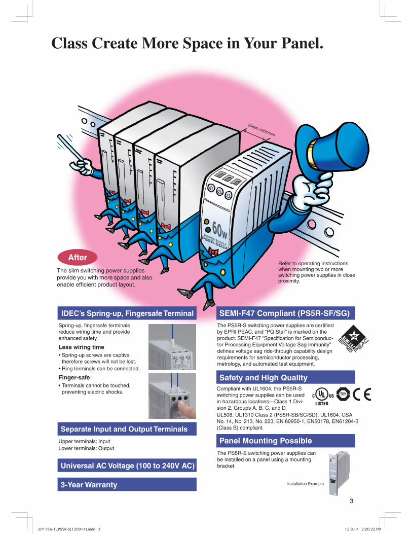
After
Class Create More Space in Your Panel.
The slim switching power supplies provide you with more space and also enable efficient product layout.
IDEC’s Spring-up, Fingersafe Terminal SEMI-F47 Compliant (PS5R-SF/SG)
Safety and High Quality
Panel Mounting Possible
Separate Input and Output Terminals
Spring-up, fingersafe terminals reduce wiring time and provide enhanced safety.
Less wiring timepring-up screws are captive,
therefore screws will not be lost.Ring terminals can be connected.
Finger-safeerminals cannot be touched,
preventing electric shocks.
Upper terminals: InputLower terminals: Output
Universal AC Voltage (100 to 240V AC)
3-Year Warranty
The PS5R-S switching power supplies are certified by EPRI PEAC, and “PQ Star” is marked on the product. SEMI-F47 “Specification for Semiconduc-tor Processing Equipment Voltage Sag Immunity” defines voltage sag ride-through capability design requirements for semiconductor processing, metrology, and automated test equipment.
Refer to operating instructions when mounting two or more switching power supplies in close proximity.
Compliant with UL1604, the PS5R-S switching power supplies can be used in hazardous locations—Class 1 Divi-sion 2, Groups A, B, C, and D.UL508, UL1310 Class 2 (PS5R-SB/SC/SD), UL1604, CSA No. 14, No. 213, No. 223, EN 60950-1, EN50178, EN61204-3 (Class B) compliant.
The PS5R-S switching power supplies can be installed on a panel using a mounting bracket.
Installation Example
3

4
PS5R-S Switching Power SuppliesSlim size DIN rail mount switching power supplies with finger-safe terminals Universal input; Wide power range 10W, 15W, 30W, 60W, 90W, 120W, and 240W
Applicable Standards Mark File No. or Organization
UL508ANSI/ISA-12.12.01-2007UL1310 Class 2 (PS5R-SB/SC/SD)CSA C22.2 No. 14/213CSA C22.2 No. 223 (PS5R-SB/SC/SD)
UL/c-UL File No. E234997
EN60950-1EN50178EN61204-3
TÜV SÜD
EU Low Voltage and EMC Directives
SEMI F47 (PS5R-SF/SG) EPRI PEAC
• Compact and light-weight Width: 22.5 mm (10W/15W), 36 mm (30W/60W), 46 mm (90W), 50 mm (120W), 80 mm (240W)
• Universal AC input (DC compatible)
• DIN rail mounting. Optional mounting bracket is available for panel surface mount.
• IP20 fingersafe spring-up screw terminals
• CE marked (LVD and EMCD)
• EN61204-3 (DC power supply EMC Directive Class B) approval, VCCI Class B compliant
PS5R-SOutput
Capacity Part No. Input Voltage Output Voltage
Output Current
10W PS5R-SB05
100 to 240V AC (Voltage range: 85 to 264V AC, 100 to 370V DC)
5V 2.0A
15WPS5R-SB12 12V 1.2APS5R-SB24 24V 0.65A
30WPS5R-SC12 12V 2.5APS5R-SC24 24V 1.3A
60W PS5R-SD24 24V 2.5A90W PS5R-SE24 24V 3.75A
120W PS5R-SF24 100 to 240V AC (Voltage range: 85 to 264V AC, 100 to 350V DC)
24V 5.0A
240W PS5R-SG24 24V 10.0A
DIN RailShape Specifications Part No. Ordering No. Package Quantity Remarks
AluminumWeight: Approx. 200g BAA1000 BAA1000PN10 10
Length: 1mWidth: 35 mmSteel
Weight: Approx. 320g BAP1000 BAP1000PN10 10
End ClipShape Specifications Part No. Ordering No. Package Quantity Remarks
Zinc-plated steelWeight: Approx. 15g
BNL5 BNL5PN10 10Used on a DIN rail to fasten switching power supplies.
BNL6 BNL6PN10 10
Panel Mounting BracketApplicable Switching
Power Supply Ordering No. Package Quantity Remarks
PS5R-SBPS9Z-5R1B 1 For upright mountingPS9Z-5R2B 1 For flat mounting
PS5R-SCPS5R-SD PS9Z-5R1C 1 For upright mounting
PS5R-SE PS9Z-5R1E 1 For upright mountingPS5R-SFPS5R-SG PS9Z-5R1G 1 For upright mounting
Output Voltage Code05: 5V DC (PS5R-SB only) 12: 12V DC (PS5R-SB/SC only)24: 24V DC
Output Capacity CodeB: 10W/15WC: 30WD: 60WE: 90WF: 120WG: 240W
PS5R - S
Part No. Development
Slim Size
5
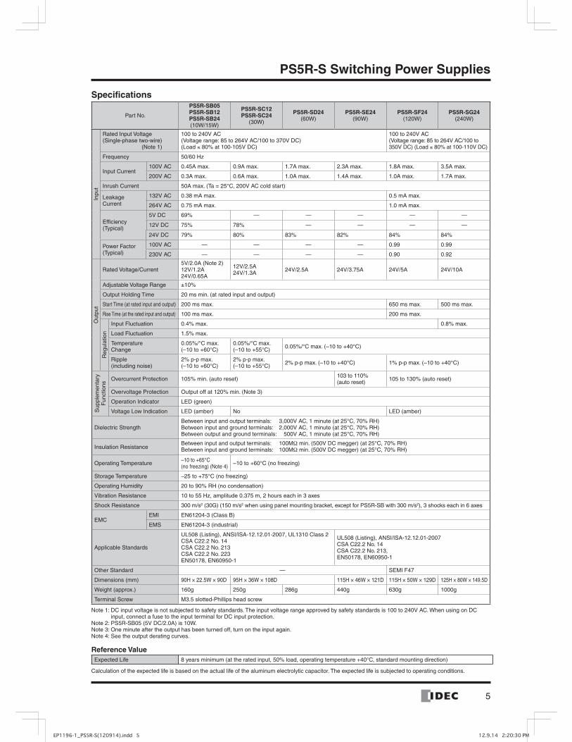
Specifications
Part No.
PS5R-SB05PS5R-SB12PS5R-SB24(10W/15W)
PS5R-SC12PS5R-SC24
(30W)
PS5R-SD24(60W)
PS5R-SE24(90W)
PS5R-SF24(120W)
PS5R-SG24(240W)
Inpu
t
Rated Input Voltage(Single-phase two-wire) (Note 1)
100 to 240V AC(Voltage range: 85 to 264V AC/100 to 370V DC)(Load ≤ 80% at 100-105V DC)
100 to 240V AC(Voltage range: 85 to 264V AC/100 to 350V DC) (Load ≤ 80% at 100-110V DC)
Frequency 50/60 Hz
Input Current100V AC 0.45A max. 0.9A max. 1.7A max. 2.3A max. 1.8A max. 3.5A max.
200V AC 0.3A max. 0.6A max. 1.0A max. 1.4A max. 1.0A max. 1.7A max.
Inrush Current 50A max. (Ta = 25°C, 200V AC cold start)
Leakage Current
132V AC 0.38 mA max. 0.5 mA max.
264V AC 0.75 mA max. 1.0 mA max.
Efficiency (Typical)
5V DC 69% — — — — —
12V DC 75% 78% — — — —
24V DC 79% 80% 83% 82% 84% 84%
Power Factor (Typical)
100V AC — — — — 0.99 0.99
230V AC — — — — 0.90 0.92
Out
put
Rated Voltage/Current5V/2.0A (Note 2)12V/1.2A24V/0.65A
12V/2.5A24V/1.3A 24V/2.5A 24V/3.75A 24V/5A 24V/10A
Adjustable Voltage Range ±10%
Output Holding Time 20 ms min. (at rated input and output)
Start Time (at rated input and output) 200 ms max. 650 ms max. 500 ms max.
Rise Time (at the rated input and output) 100 ms max. 200 ms max.
Reg
ulat
ion
Input Fluctuation 0.4% max. 0.8% max.
Load Fluctuation 1.5% max.
Temperature Change
0.05%/°C max.(–10 to +60°C)
0.05%/°C max.(–10 to +55°C) 0.05%/°C max. (–10 to +40°C)
Ripple (including noise)
2% p-p max.(–10 to +60°C)
2% p-p max.(–10 to +55°C) 2% p-p max. (–10 to +40°C) 1% p-p max. (–10 to +40°C)
Sup
plem
enta
ry
Fun
ctio
ns
Overcurrent Protection 105% min. (auto reset) 103 to 110% (auto reset) 105 to 130% (auto reset)
Overvoltage Protection Output off at 120% min. (Note 3)
Operation Indicator LED (green)
Voltage Low Indication LED (amber) No LED (amber)
Dielectric StrengthBetween input and output terminals: 3,000V AC, 1 minute (at 25°C, 70% RH) Between input and ground terminals: 2,000V AC, 1 minute (at 25°C, 70% RH)Between output and ground terminals: 500V AC, 1 minute (at 25°C, 70% RH)
Insulation ResistanceBetween input and output terminals: 100MΩ min. (500V DC megger) (at 25°C, 70% RH)Between input and ground terminals: 100MΩ min. (500V DC megger) (at 25°C, 70% RH)
Operating Temperature –10 to +65°C (no freezing) (Note 4) –10 to +60°C (no freezing)
Storage Temperature –25 to +75°C (no freezing)
Operating Humidity 20 to 90% RH (no condensation)
Vibration Resistance 10 to 55 Hz, amplitude 0.375 m, 2 hours each in 3 axes
Shock Resistance 300 m/s2 (30G) (150 m/s2 when using panel mounting bracket, except for PS5R-SB with 300 m/s2), 3 shocks each in 6 axes
EMCEMI EN61204-3 (Class B)
EMS EN61204-3 (industrial)
Applicable Standards
UL508 (Listing), ANSI/ISA-12.12.01-2007, UL1310 Class 2CSA C22.2 No. 14CSA C22.2 No. 213CSA C22.2 No. 223EN50178, EN60950-1
UL508 (Listing), ANSI/ISA-12.12.01-2007CSA C22.2 No. 14CSA C22.2 No. 213, EN50178, EN60950-1
Other Standard — SEMI F47
Dimensions (mm) 90H × 22.5W × 90D 95H × 36W × 108D 115H × 46W × 121D 115H × 50W × 129D 125H × 80W × 149.5D
Weight (approx.) 160g 250g 286g 440g 630g 1000g
Terminal Screw M3.5 slotted-Phillips head screw
Note 1: DC input voltage is not subjected to safety standards. The input voltage range approved by safety standards is 100 to 240V AC. When using on DC input, connect a fuse to the input terminal for DC input protection.
Note 2: PS5R-SB05 (5V DC/2.0A) is 10W.Note 3: One minute after the output has been turned off, turn on the input again.Note 4: See the output derating curves.
Reference ValueExpected Life 8 years minimum (at the rated input, 50% load, operating temperature +40°C, standard mounting direction)
Calculation of the expected life is based on the actual life of the aluminum electrolytic capacitor. The expected life is subjected to operating conditions.
PS5R-S Switching Power Supplies
6
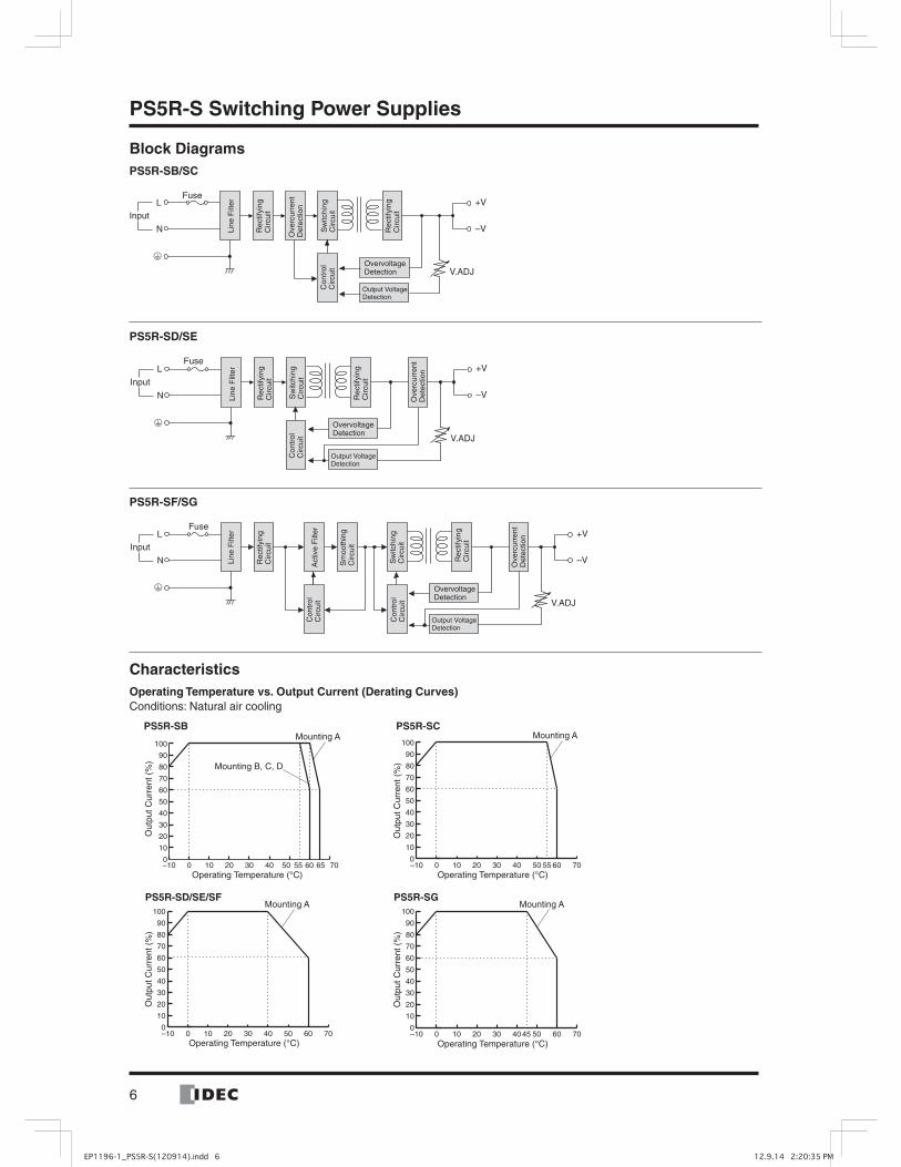
PS5R-S Switching Power Supplies
Block DiagramsPS5R-SB/SC
PS5R-SD/SE
PS5R-SF/SG
CharacteristicsOperating Temperature vs. Output Current (Derating Curves)Conditions: Natural air cooling
V.ADJ
FuseL
N
Input
+V
–VLine
Filt
er
Rec
tifyi
ngC
ircui
t
Ove
rcur
rent
D
etec
tion
Sw
itchi
ngC
ircui
tC
ontr
olC
ircui
t
Rec
tifyi
ngC
ircui
t
OvervoltageDetection
Output VoltageDetection
V.ADJ
L
N
Input
Fuse+V
–VLine
Filt
er
Rec
tifyi
ngC
ircui
t
Rec
tifyi
ngC
ircui
t
Ove
rcur
rent
D
etec
tion
Sw
itchi
ngC
ircui
tC
ontr
olC
ircui
t
OvervoltageDetection
Output VoltageDetection
L
N
Input
V.ADJ
+V
–V
Fuse
Line
Filt
er
Act
ive
Filt
er
Rec
tifyi
ngC
ircui
t
Ove
rcur
rent
D
etec
tion
Sw
itchi
ngC
ircui
t
Sm
ooth
ing
Circ
uit
Con
trol
Circ
uit
Con
trol
Circ
uit
Rec
tifyi
ngC
ircui
t
OvervoltageDetection
Output VoltageDetection
–10 0 10 20 30 40 50 60 700
10
20
30
40
50
60
70
80
90
100
Operating Temperature (°C)
Out
put C
urre
nt (
%)
Mounting A
–10 0 10 20 30 40 50 60 6555 700
10
20
30
40
50
60
70
80
90
100
Out
put C
urre
nt (
%)
Operating Temperature (°C)
Mounting A
Mounting B, C, D
–10 0 10 20 30 40 50 55 60 700
10
20
30
40
50
60
70
80
90
100
Operating Temperature (°C)
Out
put C
urre
nt (
%)
Mounting A
–10 0 10 20 30 40 45 50 60 700
10
20
30
40
50
60
70
80
90
100
Operating Temperature (°C)
Out
put C
urre
nt (
%)
Mounting A
PS5R-SC
PS5R-SD/SE/SF PS5R-SG
PS5R-SB

7
PS5R-S Switching Power Supplies
Operating Temperature Approved by Safety Standards UL 508, EN 60950-1, and EN 50178
Part No.UL 508 EN 60950-1, EN 50178
Mounting A Mounting B, C, and D Mounting A Mounting B, C, and D
PS5R-SB05, -SB12, -SB24 55 55 60 55
PS5R-SC12, -SC24 55 Impossible 55 Impossible
PS5R-SD24, -SE24, -SF24 40 Impossible 40 Impossible
PS5R-SG24 45 Impossible 45 Impossible
Mounting Style
Overcurrent Protection Characteristics
Mounting A(Vertical)
Mounting B(Upright)
Mounting C(Left side up)
Up
Mounting D(Right side up)
PS5R-SB onlyAll models
PS5R-SC
00
100
105%
100
Intermittent Operation
Output Current (%)
Out
put V
olta
ge (
%)
0 1000
100
105%
Intermittent Operation
Output Current (%)
Out
put V
olta
ge (
%)
0 1000
100
103% 110%
Intermittent Operation
Output Current (%)
Out
put V
olta
ge (
%)
PS5R-SD
PS5R-SE PS5R-SF/SG
0 1000
100
105% 130%
Output Current (%)
Out
put V
olta
ge (
%)
PS5R-SB
100
0100 105
Output Current (%)
Out
put V
olta
ge (
%)
8
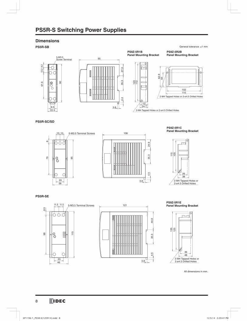
PS5R-S Switching Power Supplies
DimensionsPS5R-SB
PS5R-SC/SD
PS5R-SE
3.8
95
4.4
35.3
27.3
61.6
12.2
8.2
90
9.522.5
1224.7
12
011
2
102110
62
.94
4
5-M3.5 Screw Terminal
2-M4 Tapped Holes or 2-ø4.5 Drilled Holes
2-M4 Tapped Holes or 2-ø4.5 Drilled Holes
PS9Z-5R2B Panel Mounting Bracket
PS9Z-5R1B Panel Mounting Bracket
General tolerance: ±1 mm
108
3.8
4.5
24.9
35.3
36
95798
20
10 10
115
105
2638
2-M4 Tapped Holes or2-ø4.5 Drilled Holes
5-M3.5 Terminal Screws
PS9Z-5R1C Panel Mounting Bracket
4.5
44.9
35.3
3.8
121
115
988.
5
4623
11.5 11.5 5-M3.5 Terminal Screws
3648
135
125
2-M4 Tapped Holes or2-ø4.5 Drilled Holes
PS9Z-5R1E Panel Mounting Bracket
All dimensions in mm.

9
PS5R-S Switching Power Supplies
PS5R-SF
PS5R-SG
135
145
48
36
3.8
4.5
44.9
35.3
12911.511.5
115
50.0
23.0
9.1
96.8
5-M3.5 Terminal Screws
4-M4 Tapped Holes or4-ø4.5 Drilled Holes
PS9Z-5R1G Panel Mounting Bracket
General tolerance: ±1 mm
All dimensions in mm.
135
145
48
363.8
4.5
35.3
54.9
149.5
1010
80
10 10
10 10
9.4
106.
3
125
7-M3.5 Terminal Screws
4-M4 Tapped Holes or4-ø4.5 Drilled Holes
PS9Z-5R1G Panel Mounting Bracket

10
PS5R-S Switching Power Supplies
• Do not use switching power supplies with electric equipment whose malfunction or inadvertent operation may damage the human body or life directly.
• Make sure that the input voltage and output current do not ex ceed the ratings. If the input voltage and output current exceed the ratings, electric shock, fire, or malfunction may occur.
• Do not touch the terminals of the switching power supply while input voltage is applied, otherwise electric shock may occur.
• Provide the final product with protection against malfunction or damage that may be caused by malfunction of the switch-ing power supply.
• Operating temperatures should not exceed the ratings. Be sure to note the derating characteristics. If the operating tem-perature exceeds the ratings, electric shock, fire, or malfunc-tion may occur.
• Blown fuses indicate that the internal circuits are damaged. Contact IDEC for repair. Do not just replace the fuse and reop erate, otherwise electric shock, fire, or malfunction may occur.
• Do not use the switching power supplies to charge recharge-able batteries.
• Do not overload or short-circuit the switching power supply for a long period of time, otherwise the internal elements may be damaged.
• Do not disassemble, repair, or modify the power supplies, oth-erwise the high voltage internal part may cause electric shock, fire, or malfunction.
Safety Precautions
Parts Description
LINPUT 50/60Hz
VR.ADJ
DC ON
N
-V
OUTPUT
+V
-V +V
100-240VAC
INPUT
VR.ADJ
ON
LOW
OUTPUT
PS5R-SC/SD/SE
PS5R-SF/SG
Marking Name Description
VR.ADJ Output Voltage Adjustment
Allows adjustment within ±10%. Turning clockwise increases the output voltage.
DC ON Operation Indicator (Green) Lights on when the output voltage is on.
DC Low Output Low Indicator (Amber)
Lights on when the output voltage drops blow approx. 80% of the rated value (PS5R-SB/SF/SG only).
+V–V
DC Output Terminals +V: Positive output terminal–V: Negative output terminal
Ground Terminal Be sure to connect this terminal to a proper ground.
LN
Input Terminal Accept a wide range of voltage and frequency. Polarity is irrelevant at DC input.
DC ON and DC Low IndicatorsWhen the output voltage drops below approx. 80% of the rated value because of the activation of overcurrent protection or low input voltage, the DC Low LED goes on (PS5R-SB/SF/SG only).The status of the switching power supply can be seen from the DC ON and DC Low indicators.
Status Normal Overload or Input Voltage Low∗
Output Short-circuit Output OFF
DC ON LED (Green) ON ON OFF OFF
DC Low LED (Amber) OFF ON ON OFF
∗ The LEDs go on when the input voltage drops below 57V AC at full load.
PS5R-SB

11
PS5R-S Switching Power Supplies
Notes for Installation1. When mounting the PS5R-S switching power supply, be sure
to prevent heat built-up around the PS5R-S, taking the fol-lowing precautions into consideration.
(1) Do not close the top and bottom openings of the PS5R-S to allow for heat radiation by convection.
(2) Maintain a minimum of 20 mm clearance around the PS5R-S, except for the top and bottom openings.
(3) When derating of the output does not work, provide forced air-cooling.
(4) For wiring, use wires with heat resistance of 60°C or higher.(5) Recommended tightening torque of the input and output ter-
minals is 0.8 N·m (UL listed torque value). Do not tighten to 1.8 N·m or higher.
(6) Use copper core wires of the following sizes. Recommended wire size: AWG14 to 18
(cross section: 0.9 to 2 mm2)2. When mounting multiple PS5R-S switching power supplies
side by side, maintain a minimum of 20 mm clearance. Observe the derating curves in consideration of the ambient temperature.
3. Mounting on 35-mm-wide DIN rails
MountingFasten the DIN rail to a mounting plate using screws firmly.When mounting the PS5R-S on a DIN rail, place the PS5R-S as shown. With the clamp inserted, press the PS5R-S towards the DIN rail.
RemovalInsert a flat screwdriver into the slot in the clamp, and pull out the clamp until it clicks. Turn the PS5R-S bottom out.
4. Installing the Panel Mounting Bracket
<Installing PS9Z-5R2B Panel Mounting Bracket>
Latch
Panel Mounting Bracket (PS9Z-5R1)
PowerSupply
Tab
Slot
LOCK
LOCK
UNLOCK
LOCK
UNLOCK
Panel Mounting Bracket (PS9Z-5R2B)
PowerSupply
Latch
Tab
LOCK
<Installing PS9Z-5R1 Panel Mounting Bracket>
Ç Insert the tab on the panel mounting bracket into the slot on the power supply.
É Install the bracket as shown on the left.
Å Push in the latch to LOCKposition.
Å Pull out the latch toUNLOCK position.
Ç Insert the tab on the panel mounting bracket into the slot on the power supply.
É Push in the latch to LOCK position.
Ñ Ensure that the panel mounting bracket is locked by the latch.
Ñ Ensure that the panel mounting bracket is locked by the latch.Ñ
É
É
Adjustment of Output VoltageThe output voltage can be adjusted within ±10% of the rated output voltage by using the VR.ADJ control on the front. Turning the VR.ADJ clockwise increases the output voltage. When using a higher output voltage, reduce the output current to make sure that the output capacity is within the rating. Note that over voltage protection may work when increasing the output volt age.Overcurrent ProtectionThe output voltage drops automatically when an overcurrent flows due to an overload or short circuit. Normal voltage is auto matically restored when the load returns to normal conditions.Overvoltage Protection (OVP)The output is turned off by overvoltage protection when an over voltage is applied. When the output voltage has dropped due to an overvoltage, turn the input off, and after one minute, turn the input on again.
Air
20 mm minimum
Mounting Removal
Clamp
Instructions
PS5R-S Switching Power Supplies
IDEC CORPORATION (USA)1175 Elko DriveSunnyvale, CA 94089-2209, USATel: +1-408-747-0550 / (800) 262-IDEC (4332) Fax: +1-408-744-9055 / (800) 635-6246E-mail: [email protected]
IDEC CANADA LIMITED3155 Pepper Mill Court, Unit 4Mississauga, Ontario, L5L 4X7, CanadaTel: +1-905-890-8561Toll Free: (800) 262-IDEC (4332) Fax: +1-905-890-8562E-mail: [email protected]
IDEC AUSTRALIA PTY. LTD.Unit 17, 104 Ferntree Gully Road,Oakleigh, Victoria 3166, AustraliaTel: +61-3-8523-5900, Toll Free: 1800-68-4332Fax: +61-3-8523-5999E-mail: [email protected]
7-31, Nishi-Miyahara 1-Chome, Yodogawa-ku, Osaka 532-8550, JapanTel: +81-6-6398-2571, Fax: +81-6-6392-9731E-mail: [email protected]
Specifications and other descriptions in this catalog are subject to change without notice.
Cat. No. EP1196-2 MARCH 2013 1 PRINTED IN SINGAPORE
IDEC ELECTRONICS LIMITEDUnit 2, Beechwood, Chineham Business Park, Basingstoke, Hampshire RG24 8WA, UKTel: +44-1256-321000, Fax: +44-1256-327755E-mail: [email protected]
IDEC ELEKTROTECHNIK GmbHWendenstrasse 331, 20537 Hamburg, GermanyTel: +49-40-25 30 54 - 0, Fax: +49-40-25 30 54 - 24E-mail: [email protected]
IDEC (SHANGHAI) CORPORATIONRoom 701-702 Chong Hing Finance Center, No. 288 Nanjing Road West, Shanghai 200003, PRCTel: +86-21-6135-1515 Fax: +86-21-6135-6225 / +86-21-6135-6226E-mail: [email protected]
IDEC (BEIJING) CORPORATIONRoom 211B, Tower B, The Grand Pacific Building, 8A Guanghua Road, Chaoyang District, Beijing 100026, PRCTel: +86-10-6581-6131, Fax: +86-10-6581-5119
IDEC (SHENZHEN) CORPORATIONUnit AB-3B2, Tian Xiang Building, Tian’an Cyber Park, Fu Tian District, Shenzhen, Guang Dong 518040, PRCTel: +86-755-8356-2977, Fax: +86-755-8356-2944
IDEC IZUMI (H.K.) CO., LTD.Units 11-15, Level 27, Tower 1, Millennium City 1, 388 Kwun Tong Road, Kwun Tong, Kowloon, Hong KongTel: +852-2803-8989, Fax: +852-2565-0171E-mail: [email protected]
IDEC TAIWAN CORPORATION8F-1, No. 79, Hsin Tai Wu Road, Sec. 1, Hsi-Chih District, 22101 New Taipei City, Taiwan Tel: +886-2-2698-3929, Fax: +886-2-2698-3931E-mail: [email protected]
IDEC IZUMI ASIA PTE. LTD.No. 31, Tannery Lane #05-01,HB Centre 2, Singapore 347788Tel: +65-6746-1155, Fax: +65-6844-5995E-mail: [email protected]
www.idec.com
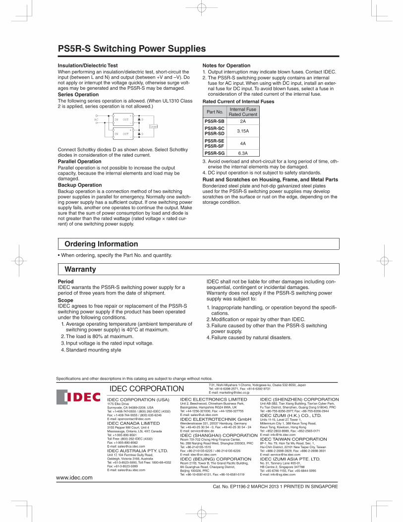
Insulation/Dielectric Test
When performing an insulation/dielectric test, short-circuit the input (between L and N) and output (between +V and –V). Do not apply or interrupt the voltage quickly, otherwise surge volt-ages may be generated and the PS5R-S may be damaged.Series Operation
The following series operation is allowed. (When UL1310 Class 2 is applied, series operation is not allowed.)
Connect Schottky diodes D as shown above. Select Schottky diodes in consideration of the rated current.Parallel Operation
Parallel operation is not possible to increase the output capacity, because the internal elements and load may be damaged.Backup Operation
Backup operation is a connection method of two switching power supplies in parallel for emergency. Normally one switch-ing power supply has a sufficient output. If one switching power supply fails, another one operates to continue the output. Make sure that the sum of power consumption by load and diode is not greater than the rated wattage (rated voltage × rated cur-rent) of one switching power supply.
Notes for Operation
1. Output interruption may indicate blown fuses. Contact IDEC.2. The PS5R-S switching power supply contains an internal
fuse for AC input. When using with DC input, install an exter-nal fuse for DC input. To avoid blown fuses, select a fuse in consideration of the rated current of the internal fuse.
Rated Current of Internal Fuses
Part No. Internal Fuse Rated Current
PS5R-SB 2A
PS5R-SC
PS5R-SD3.15A
PS5R-SE
PS5R-SF4A
PS5R-SG 6.3A
3. Avoid overload and short-circuit for a long period of time, oth-erwise the internal elements may be damaged.
4. DC input operation is not subject to safety standards.Rust and Scratches on Housing, Frame, and Metal Parts
Bonderized steel plate and hot-dip galvanized steel plates used for the PS5R-S switching power supplies may develop scratches on the surface or rust on the edge, depending on the storage condition.
+
–INAC OUT
+
–IN OUT
Load
D
D
Period IDEC warrants the PS5R-S switching power supply for a period of three years from the date of shipment.Scope IDEC agrees to free repair or replacement of the PS5R-S switching power supply if the product has been operated under the following conditions.
1. Average operating temperature (ambient temperature of switching power supply) is 40°C at maximum.
2. The load is 80% at maximum.3. Input voltage is the rated input voltage.4. Standard mounting style
IDEC shall not be liable for other damages including con-sequential, contingent or incidental damages.Warranty does not apply if the PS5R-S switching power supply was subject to:
1. Inappropriate handling, or operation beyond the specifi-cations.
2. Modification or repair by other than IDEC.3. Failure caused by other than the PS5R-S switching
power supply.4. Failure caused by natural disasters.
Ordering Information
Warranty