catalog nc 82 2015 - marinecy · catalog nc 82 · 2014 ... alongside two high-performance cnc...
TRANSCRIPT

Motion Control
SINUMERIK 828Equipment for Machine Tools
CatalogNC 82
Edition2015
© Siemens AG 2015

Motion Control NC 62SINUMERIK 840D sl Type 1BEquipment for Machine Tools
E86060-K4462-A101-A1-7600
SITRAIN ITCTraining for Industry
Only available in GermanE86060-K6850-A101-C4
Products for Automation CA 01and DrivesInteractive Catalog, DVD
E86060-D4001-A510-D4-7600
Industry MallInformation and Ordering Platformin the Internet:
www.siemens.com/industrymall
Related catalogs
© Siemens AG 2015

Introduction 1
Overview of functionsCNC controls SINUMERIK 828
2
CNC controls SINUMERIK 828D BASIC SINUMERIK 828D
3
SINAMICS S120 drive systemSINAMICS S120 CombiSINAMICS S120
4
SIMOTICS motorsSIMOTICS S-1FK7 feed motorsSIMOTICS M-1PH8 spindle motors
5
Measuring systemsIncremental encoders Absolute encoders
6
MOTION-CONNECT connection systemsConnection overviewsPower cablesSignal cables
7
Services and trainingServices Documentation · Training Engineering software · Applications
8
SINUMERIK Solution Partners 9
AppendixApprovals · Indexes Conversion tables · Metal surchargesConditions of sale and delivery/Export regulations
10
SINUMERIK 828Equipment for Machine Tools
Motion Control
Catalog NC 82 · 2015
Supersedes:Catalog NC 82 · 2014
Refer to the Industry Mall for current updates of this catalog:www.siemens.com/industrymall
The products contained in this catalog can also be found in the Interactive Catalog CA 01.Article No.: E86060-D4001-A510-D4-7600
Please contact your local Siemens branch.
© Siemens AG 2015
The products and systems described in this catalog are distributed under application of a certified quality management system in accordance with DIN EN ISO 9001. The certificate is recognized by all IQNet countries.
© Siemens AG 2015
2 Siemens NC 82 · 2015
© Siemens AG 2015

3Siemens NC 82 · 2015
Answers for industry.
Integrated technologies, vertical market expertise and services
for greater productivity, energy efficiency, and flexibility.
Siemens is the world's leading supplier of innovative and environmentally friendly products and solutions for industrial companies. End-to-end automation technology and industrial software, solid market expertise, and technology-based services are the levers we use to increase our customers’ productivity, efficiency and flexibility.
We consistently rely on integrated tech-nologies and, thanks to our bundled portfolio, we can respond more quickly and flexibly to our customers' wishes. With our globally unmatched range of automation technology, industrial control and drive technology as well as industrial software, we equip compa-nies with exactly what they need over their entire value chain – from product design and development to production, sales and service. Our industrial custom-ers benefit from our comprehensive portfolio, which is tailored to their market and their needs.
Market launch times can be reduced by up to 50% due to the combination of powerful automation technology and industrial software. At the same time, the costs for energy or waste water for a manufacturing company can be reduced significantly. In this way, we increase our customers’ competitive strength and make an important contribution to environmen-tal protection with our energy-efficient products and solutions.
© Siemens AG 2015
4 Siemens NC 82 · 2015
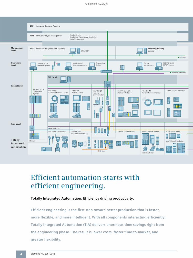
Efficient automation starts with efficient engineering.
Totally Integrated Automation: Efficiency driving productivity.
Efficient engineering is the first step toward better production that is faster,
more flexible, and more intelligent. With all components interacting efficiently,
Totally Integrated Automation (TIA) delivers enormous time savings right from
the engineering phase. The result is lower costs, faster time-to-market, and
greater flexibility.
© Siemens AG 2015
5Siemens NC 82 · 2015
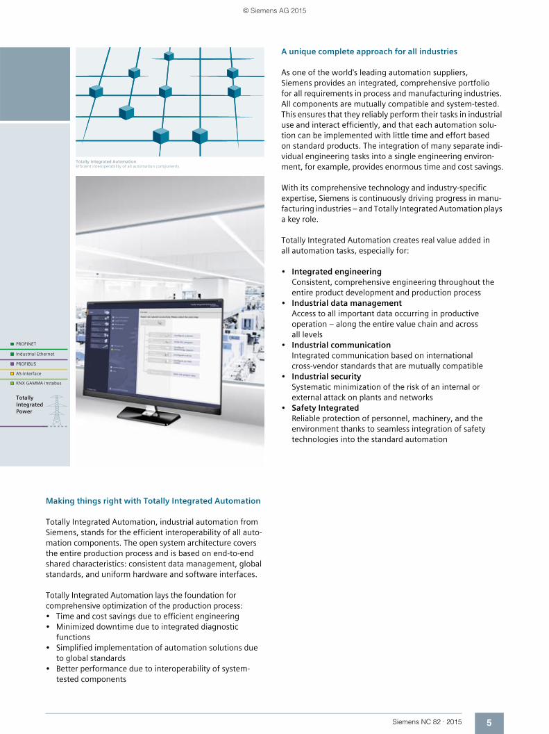
Totally Integrated AutomationEfficient interoperability of all automation components
Making things right with Totally Integrated Automation
Totally Integrated Automation, industrial automation from Siemens, stands for the efficient interoperability of all auto-mation components. The open system architecture covers the entire production process and is based on end-to-end shared characteristics: consistent data management, global standards, and uniform hardware and software interfaces.
Totally Integrated Automation lays the foundation for comprehensive optimization of the production process:• Time and cost savings due to efficient engineering• Minimized downtime due to integrated diagnostic
functions• Simplified implementation of automation solutions due
to global standards• Better performance due to interoperability of system-
tested components
A unique complete approach for all industries
As one of the world's leading automation suppliers, Siemens provides an integrated, comprehensive portfolio for all requirements in process and manufacturing industries. All components are mutually compatible and system-tested. This ensures that they reliably perform their tasks in industrial use and interact efficiently, and that each automation solu-tion can be implemented with little time and effort based on standard products. The integration of many separate indi-vidual engineering tasks into a single engineering environ-ment, for example, provides enormous time and cost savings.
With its comprehensive technology and industry-specific expertise, Siemens is continuously driving progress in manu-facturing industries – and Totally Integrated Automation plays a key role.
Totally Integrated Automation creates real value added in all automation tasks, especially for:
• Integrated engineeringConsistent, comprehensive engineering throughout the entire product development and production process
• Industrial data managementAccess to all important data occurring in productive operation – along the entire value chain and across all levels
• Industrial communicationIntegrated communication based on international cross-vendor standards that are mutually compatible
• Industrial securitySystematic minimization of the risk of an internal or external attack on plants and networks
• Safety IntegratedReliable protection of personnel, machinery, and the environment thanks to seamless integration of safety technologies into the standard automation
© Siemens AG 2015

6 Siemens NC 82 · 2015
© Siemens AG 2015

Siemens NC 82 · 2015
11/2 CNC controls1/2 SINUMERIK – a CNC portfolio
for the global world of machine tools
1/3 SINUMERIK 828
1/5 Drive system1/5 SINAMICS S120 drive system
1/6 Motors1/6 SIMOTICS motors
1/7 The overall system1/7 SINUMERIK 828D BASIC/SINUMERIK 828D
with SINAMICS S120 and SIMOTICS motors
1/8 SINUMERIK Safety Integrated
1/9 Energy efficiency
Introduction
© Siemens AG 2015
1/2 Siemens NC 82 · 2015
1
IntroductionCNC controls
SINUMERIK – a CNC portfolio for the global world of machine tools
■ Overview
G_NC01_EN_00547d
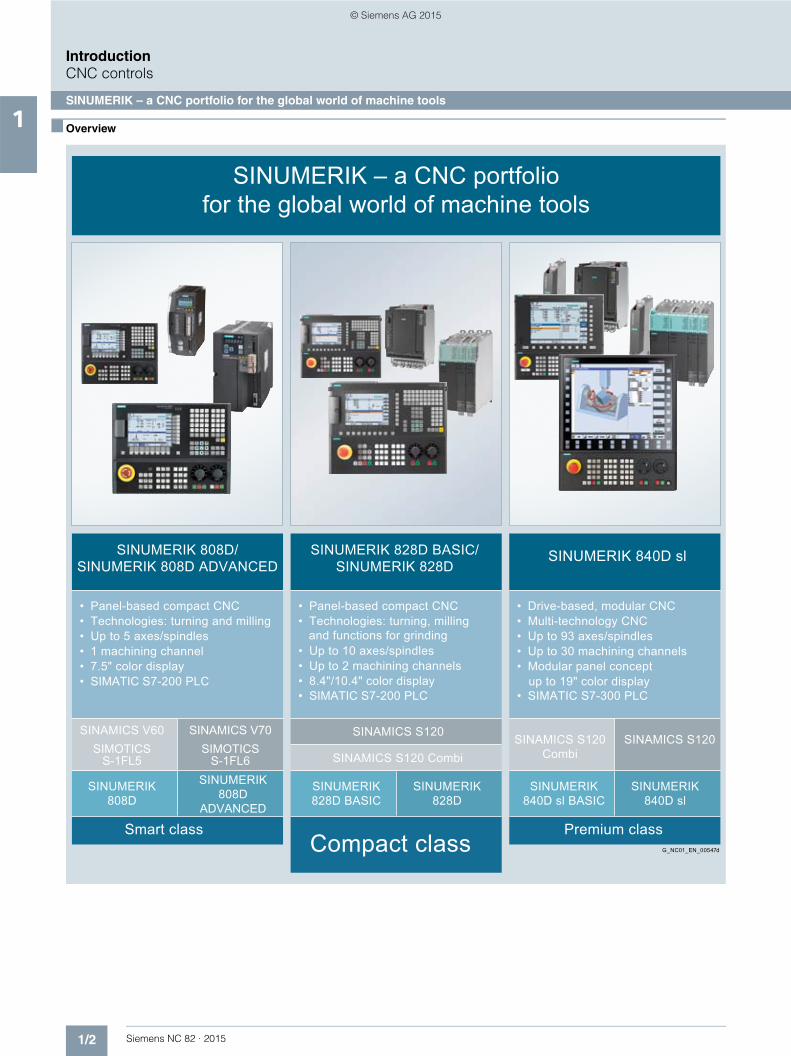
SINUMERIK – a CNC portfolio for the global world of machine tools
Premium class
SINUMERIK 840D sl
SINUMERIK 840D sl BASIC
SINAMICS S120SINAMICS S120 Combi
• SIMATIC S7-300 PLCup to 19" color display
• Modular panel concept • Up to 30 machining channels• Up to 93 axes/spindles• Multi-technology CNC• Drive-based, modular CNC
SINUMERIK 840D sl
Compact class
SINUMERIK 828D
SINUMERIK 828D BASIC
SINAMICS S120 Combi
SINAMICS S120
• SIMATIC S7-200 PLC• 8.4"/10.4" color display• Up to 2 machining channels• Up to 10 axes/spindles
• Technologies: turning, milling and functions for grinding
• Panel-based compact CNC
SINUMERIK 828D BASIC/ SINUMERIK 828D
SINUMERIK 808D/ SINUMERIK 808D ADVANCED
Smart class
SINUMERIK 808D
SINUMERIK 808D
ADVANCED
• SIMATIC S7-200 PLC• 7.5" color display• 1 machining channel• Up to 5 axes/spindles• Technologies: turning and milling• Panel-based compact CNC
SINAMICS V60 SIMOTICS
S-1FL5
SINAMICS V70 SIMOTICS
S-1FL6
© Siemens AG 2015

1/3Siemens NC 82 · 2015
1
IntroductionCNC controls
SINUMERIK 828
■ Overview
SINUMERIK 828 –Optimum scalability in the compact class
Alongside two high-performance CNC variants of SINUMERIK 828D, SINUMERIK 828D BASIC is a low-cost starter model in the compact class. SINUMERIK 828 therefore fits the performance requirements of standard machine con-cepts perfectly.
Compact, strong, simple – simply ingenious
The compact, operator-panel-based SINUMERIK 828 CNC systems are extremely rugged and very easy to maintain.
An operator panel front of die-cast magnesium, the panel-based CNC design with minimal interfaces and the high degree of protection make the SINUMERIK 828 CNC systems reliable partners even in harsh environments. Designed without a fan or hard disk, with NVRAM memory technology and no back-up battery, SINUMERIK 828 is a completely maintenance-free CNC.
Powerful CNC functions coupled with unique 80-bit NANOFP accuracy allow excellent workpiece precision to be achieved in very short machining times. Thanks to a flexible CNC program-ming language as well as the unique machining step program-ming package ShopTurn/ShopMill, it is possible to program and machine mass-production parts or single workpieces with highest efficiency. Preconfigured technology-specific system software and unique service functions reduce the costs of commissioning and servicing to an absolute minimum.
Technology tailor-made for use in standard turning and milling machines
SINUMERIK 828D is perfectly adapted to use in standard machines and provides optimum support for turning and milling technology. With two preconfigured system software variants for machining technology, the SINUMERIK 828 CNC systems are ready for use in turning and milling machines on dispatch from the factory.
An ideal basis for implementing a compact grinding machine
The G-Tech technology variant provides grinding machine manufacturers with a perfect platform on which to design grinding machines – it supports cylindrical as well as surface grinding machines.
Since grinding machine manufacturers fully incorporate their specific process know-how so that it is even reflected in the operating philosophy of the CNC, the G-Tech variant of the SINUMERIK 828D offers a number of sophisticated grinding and dressing cycles for this purpose. At the same time, SINUMERIK Integrate for engineering Run MyScreens provides manufacturers with the option of designing their own HMI.
Per
form
ance
Up to 10 MB user memory768 tools, 1536 cutting edges
Minimum block change time approximately 1 ms (Milling)
Up to 2 machining channels (Turning, G-Tech)
Up to 8 axes/spindles (Milling), Up to 10 axes/spindles (Turning, G-Tech)
5 MB user memory256 tools, 512 cutting edges
Minimum block change time approximately 2 ms (Milling)
1 machining channelUp to 6 axes/spindles
3 MB user memory128 tools, 256 cutting edges
Minimum block change time approximately 3 ms (Milling)
1 machining channelUp to 5 axes/spindles
10.4"
10.4"
8.4"
G_NC01_EN_00581a
SIN
UM
ER
IK 8
28D
SIN
UM
ER
IK 8
28D
BA
SIC
PPU 280.3/281.3
PPU 260.3/261.3
PPU 240.3/241.3
© Siemens AG 2015

1/4 Siemens NC 82 · 2015
1 ■ Overview (continued)
IntroductionCNC controls
SINUMERIK 828
The right performance for the relevant technology – scalable by selection of appropriate software
SINUMERIK 828D offers the right performance level for any compact machine. One of four different performance variants can be used depending on the requirements of the application in terms of channels, axis quantity structures, and the cycle times of the interpolator and position controller. The performance variant is numerically coded. The following variants are available:• SW 24x
Performance variant PPU 240/PPU 241• SW 26x
Performance variant PPU 260/PPU 261• SW 28x
Performance variant PPU 280/PPU 281• SW 28xA
Performance variant PPU 280 advanced/PPU 281 advanced
The full software designation is thus formed in conjunction with the name of one of the technologies indicated above. No performance variant PPU 28x , i.e. no software variant SW 28x Grinding, is available for the G-Tech variant.
The SINUMERIK 828D supports three technology variants: Turning, Milling, and G-Tech The relevant software variant is selected accordingly. The name of the technology variant is added to the end of the software designation, i.e. SW 2xx Turning for a lathe.
Bundling of software and hardware
The bundling process is completed by selection of suitable control system hardware (PPU). Three vertical PPUs 2x0.3 and three horizontal PPUs 2x1.3 are available for selection.
Example 1:
This means that software package SW 24x Turning is required for a lathe with 4 axes/spindles. It must then be decided whether the vertical or horizontal variant of the control system will be used. The horizontal variant is the better option for lathes so that PPU 241.3 is selected for this example application.
Example 2:
This means that software package SW 26x Milling is required for a milling machine with 6 axes/spindles. It must then be decided whether the vertical or horizontal variant of the control system will be used. The vertical variant is the better option for milling machines so that PPU 260.3 is selected for this example application.
Select performance
Select technology
Select hardware
Turning SW 24x
Milling SW 24x
Turning SW 26x
Turning SW 28x
Turning SW 28xA
Milling SW 26x
MillingSW 28x
MillingSW 28xA
G-Tech SW 24x
G-Tech SW 26x
G-TechSW 28xA
2
1
3G
_NC
01_E
N _
0102
3PPU 240.3 PPU 241.3 PPU 260.3 PPU 261.3 PPU 280.3 PPU 281.3
© Siemens AG 2015
1/5Siemens NC 82 · 2015
1
IntroductionDrive system
SINAMICS S120 drive system
■ Overview
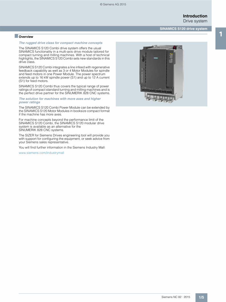
The rugged drive class for compact machine concepts
The SINAMICS S120 Combi drive system offers the usual SINAMICS functionality in a multi-axis drive module tailored for compact turning and milling machines. With a host of technical highlights, the SINAMICS S120 Combi sets new standards in this drive class.
SINAMICS S120 Combi integrates a line infeed with regenerative feedback capability as well as 3 or 4 Motor Modules for spindle and feed motors in one Power Module. The power spectrum extends up to 16 kW spindle power (S1) and up to 12 A current (S1) for feed motors.
SINAMICS S120 Combi thus covers the typical range of power ratings of compact standard turning and milling machines and is the perfect drive partner for the SINUMERIK 828 CNC systems.
The solution for machines with more axes and higher power ratings
The SINAMICS S120 Combi Power Module can be extended by the SINAMICS S120 Motor Modules in booksize compact format if the machine has more axes.
For machine concepts beyond the performance limit of the SINAMICS S120 Combi, the SINAMICS S120 modular drive system is available as an alternative for the SINUMERIK 828 CNC systems.
The SIZER for Siemens Drives engineering tool will provide you with support for configuring the equipment, or seek advice from your Siemens sales representative.
You will find further information in the Siemens Industry Mall:
www.siemens.com/industrymall
© Siemens AG 2015

1/6 Siemens NC 82 · 2015
1
IntroductionMotors
SIMOTICS motors
■ Overview
SIMOTICS S-1FK7 feed motors – maximum precision in the machine
The performance and accuracy of the CNC control and drive are useful only if they can be transferred to the machine axes. Thanks to their unique dynamic response and accuracy, SIMOTICS S-1FK7 feed motors are exactly suited for this purpose.
SIMOTICS M-1PH8 spindle motors – peak performance for the spindle
With the SIMOTICS M-1PH8 spindle motors we offer the perfect solution for this purpose. Very fast acceleration times and a wide speed range with high output guarantee maximum productivity of the machine – with speeds of up to 24000 rpm.
SIMOTICS T-1FW6 torque motors
The torque motors satisfy the most exacting demands in precision, performance and dynamic response. Permanent-magnet synchronous motors with a high number of poles are fully integrated in the machine, and mechanical transmission elements such as gear units are omitted, so you benefit from greater flexibility with regard to installation, easier servicing, higher availability and minimal space requirements.
We can also provide customized solutions
In addition to the range of motors described, we offer a compre-hensive range of solutions for feed and spindle applications. Your Siemens sales representative will be happy to advise you on how to configure your individual equipment.
You will find further information, as well as the full range of available motors, in our Catalog NC 62 or on the Siemens Industry Mall.
www.siemens.com/industrymall
© Siemens AG 2015
1/7Siemens NC 82 · 2015
1
IntroductionThe overall system
SINUMERIK 828D BASIC/SINUMERIK 828D with SINAMICS S120 Combi and SIMOTICS motors
■ Overview
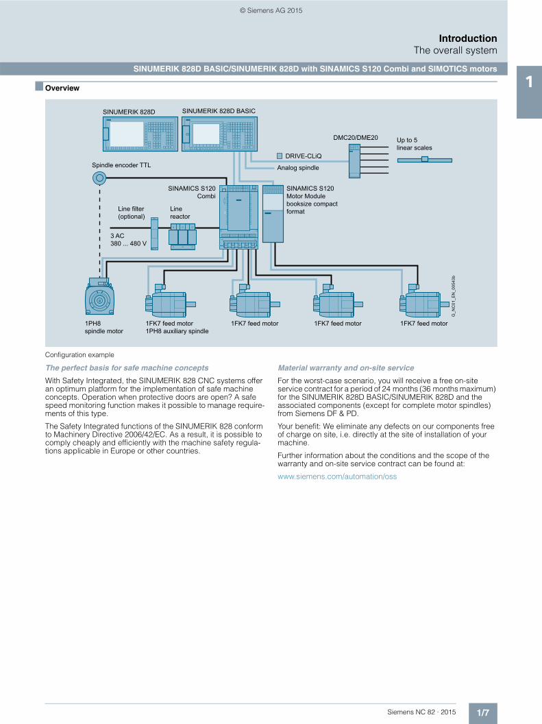
Configuration example
The perfect basis for safe machine concepts
With Safety Integrated, the SINUMERIK 828 CNC systems offer an optimum platform for the implementation of safe machine concepts. Operation when protective doors are open? A safe speed monitoring function makes it possible to manage require-ments of this type.
The Safety Integrated functions of the SINUMERIK 828 conform to Machinery Directive 2006/42/EC. As a result, it is possible to comply cheaply and efficiently with the machine safety regula-tions applicable in Europe or other countries.
Material warranty and on-site service
For the worst-case scenario, you will receive a free on-site service contract for a period of 24 months (36 months maximum) for the SINUMERIK 828D BASIC/SINUMERIK 828D and the associated components (except for complete motor spindles) from Siemens DF & PD.
Your benefit: We eliminate any defects on our components free of charge on site, i.e. directly at the site of installation of your machine.
Further information about the conditions and the scope of the warranty and on-site service contract can be found at:
www.siemens.com/automation/oss
DRIVE-CLiQ
SINAMICS S120Motor Module booksize compact format
1FK7 feed motor 1FK7 feed motor 1FK7 feed motor1FK7 feed motor1PH8 auxiliary spindle
1PH8 spindle motor
3 AC380 ... 480 V
SINAMICS S120Combi
Line reactor
Line filter (optional)
Spindle encoder TTL
Up to 5 linear scales
DMC20/DME20
G_N
C01
_EN
_005
43b
Analog spindle
SINUMERIK 828D BASIC SINUMERIK 828D
© Siemens AG 2015
1/8 Siemens NC 82 · 2015
1
IntroductionSINUMERIK Safety Integrated
■ Overview
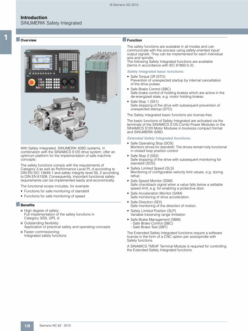
With Safety Integrated, SINUMERIK 828D systems, in combination with the SINAMICS S120 drive system, offer an optimum platform for the implementation of safe machine concepts.
The safety functions comply with the requirements of Category 3 as well as Performance Level PL d according to DIN EN ISO 13849-1 and safety integrity level SIL 2 according to DIN EN 61508. Consequently, important functional safety requirements can be implemented easily and economically.
The functional scope includes, for example:• Functions for safe monitoring of standstill• Functions for safe monitoring of speed
■ Benefits
7 High degree of safety:Full implementation of the safety functions in Category 3/SIL 2/PL d
7 Outstanding flexibility:Application of practical safety and operating concepts
7 Faster commissioning: Integrated safety functions
■ Function
The safety functions are available in all modes and can communicate with the process using safety-oriented input/output signals. They can be implemented for each individual axis and spindle. The following Safety Integrated functions are available (terms in accordance with IEC 61800-5-2):
Safety Integrated basic functions:• Safe Torque Off (STO)
Prevention of unexpected startup by internal cancellation of the drive pulses.
• Safe Brake Control (SBC)Safe brake control of holding brakes which are active in the de-energized state, e.g. motor holding brakes.
• Safe Stop 1 (SS1)Safe stopping of the drive with subsequent prevention of unexpected startup (STO).
The Safety Integrated basic functions are license-free.
The basic functions of Safety Integrated are activated via the terminals of the SINAMICS S120 Combi Power Modules or the SINAMICS S120 Motor Modules in booksize compact format and SINUMERIK 828D.
Extended Safety Integrated functions:• Safe Operating Stop (SOS)
Monitors drives for standstill. The drives remain fully functional in closed loop position control
• Safe Stop 2 (SS2) Safe stopping of the drive with subsequent monitoring for standstill (SOS).
• Safely Limited Speed (SLS)Monitoring of configurable velocity limit values, e.g. during setup.
• Safe Speed Monitor (SSM)Safe checkback signal when a value falls below a settable speed limit, e.g. for enabling a protective door.
• Safe Acceleration Monitor (SAM)Safe monitoring of drive acceleration.
• Safe Direction (SDI)Safe monitoring of the direction of motion.
• Safely Limited Position (SLP) Variable traversing range limitation
• Safe Brake Management (SBM)- Safe Brake Control (SBC)- Safe Brake Test (SBT)
The Extended Safety Integrated functions require a software license in the form of a CNC option per axis/spindle with Safety functions.
A SINAMICS TM54F Terminal Module is required for controlling the Extended Safety Integrated functions.
© Siemens AG 2015

1/9Siemens NC 82 · 2015
1
IntroductionEnergy efficiency
■ Overview
Energy is one of the most important cost factors in industry. Operators can, of course, always make savings here and there, but the full potential for saving energy can only be exploited by taking a holistic view of the entire value chain of a system. As an innovative partner, we offer industry energy-efficient solutions with products and services for all phases in the product development and production process.
5 steps toward higher energy efficiency
Exploit the full potential of energy efficiency in your production with our comprehensive range of products, systems and solu-tions, that cover all phases of the product development and pro-duction process. Our energy efficiency concept aims to continu-ously and comprehensively reduce the energy usage of machines and plants and so increase the competitiveness of our customers. To achieve this, as a leading technology partner, we accompany all phases of the product development and production process – from product design through production planning and engineer-ing – up to the production itself, and all the associated services. Only the perfect interaction of all components can achieve maxi-mum energy efficiency in production. Our continual innovations ensure that your investments in energy efficiency pay off more quickly.
Energy efficiency with SINUMERIK Ctrl-Energy
Siemens machine tool systems set the standard for energy efficiency in the machine tool: SINUMERIK Ctrl-Energy covers a wide range of highly efficient drive/motor components, CNC/drive functions, software solutions and services. SINUMERIK Ctrl-Energy offers energy-efficient solutions for the complete machine lifecycle – from the design phase to full operation. For example, intelligent functions, such as the analysis of the energy costs of the workpiece, are available to the user: Pressing the shortcut Ctrl + E helps the SINUMERIK to save energy.
Representation of current power and energy consumption for a quick overview
Graphical comparison of two measurements for qualitative evaluation of a machine tool’s energy consumption
Overview of defined energy-saving profiles for a machine tool –with pre-alarm window in the foreground
3 Production Engineering
4 Production5 Services
1 Product DesignG_D011_EN_00446a
2 Production Planning
© Siemens AG 2015

1/10 Siemens NC 82 · 2015
1
Introduction
Notes
© Siemens AG 2015
Siemens NC 82 · 2015
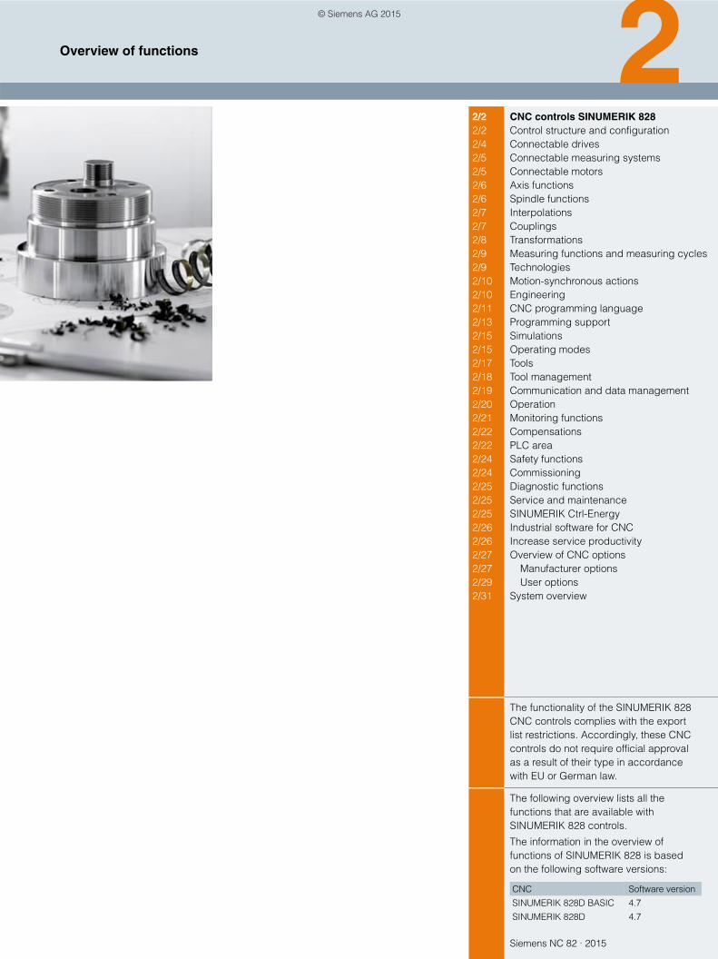
22/2 CNC controls SINUMERIK 828 2/2 Control structure and configuration2/4 Connectable drives2/5 Connectable measuring systems2/5 Connectable motors2/6 Axis functions 2/6 Spindle functions2/7 Interpolations2/7 Couplings2/8 Transformations2/9 Measuring functions and measuring cycles2/9 Technologies2/10 Motion-synchronous actions2/10 Engineering2/11 CNC programming language2/13 Programming support2/15 Simulations2/15 Operating modes2/17 Tools2/18 Tool management2/19 Communication and data management2/20 Operation2/21 Monitoring functions2/22 Compensations2/22 PLC area2/24 Safety functions2/24 Commissioning2/25 Diagnostic functions2/25 Service and maintenance2/25 SINUMERIK Ctrl-Energy2/26 Industrial software for CNC2/26 Increase service productivity2/27 Overview of CNC options2/27 Manufacturer options2/29 User options2/31 System overview
The functionality of the SINUMERIK 828 CNC controls complies with the export list restrictions. Accordingly, these CNC controls do not require official approval as a result of their type in accordance with EU or German law.
The following overview lists all the functions that are available with SINUMERIK 828 controls.
The information in the overview of functions of SINUMERIK 828 is based on the following software versions:
CNC Software version
SINUMERIK 828D BASIC 4.7
SINUMERIK 828D 4.7
Overview of functions
© Siemens AG 2015

2/2 Siemens NC 82 · 2015
Overview of functionsCNC controls SINUMERIK 828
Control structure and configuration
2
Basic version O Option – Not available
Article No. SINUMERIK 828DBASIC
Notes SW 24x SW 26x SW 28x SW 28xA
Control structure and configuration
Panel-based compact CNC comprising:
• Compact operator-panel CNC
• CNC/PLC control unit
• Closed-loop control for drives 5 6 6 6
Design, drive-based/PC-based – – – –
Operator-panel CNC:
• Horizontal
• Vertical
• Color display 8.4" 10.4" 10.4" 10.4"
• Integrated QWERTY keyboard with short-stroke keys
SINUMERIK operator panels with TCU – – – –
SINUMERIK operator panels with PCU – – – –
SINUMERIK 828D PPU:
• PPU 240.3 6FC5370-4AA30-0AA0 O – – –
• PPU 241.3 6FC5370-3AA30-0AA0 O – – –
• PPU 260.3 6FC5370-6AA30-0AA0 – O – –
• PPU 261.3 6FC5370-5AA30-0AA0 – O – –
• PPU 280.3 6FC5370-8AA30-0AA0 – – O O
• PPU 281.3 6FC5370-7AA30-0AA0 – – O O
System software, export version, on CF card, with license
• SINUMERIK 828D with PPU 240/PPU 241:
- Turning 6FC5835-1GY40-4YA0 O – – –
- Milling 6FC5835-2GY40-4YA0 O – – –
- G-Tech Cylindrical/G-Tech Surface 6FC5835-3GY40-4YA0 O – – –
• SINUMERIK 828D with PPU 260/PPU 261:
- Turning 6FC5834-1GY40-4YA0 – O – –
- Milling 6FC5834-2GY40-4YA0 – O – –
- G-Tech Cylindrical/G-Tech Surface 6FC5834-3GY40-4YA0 – O – –
• SINUMERIK 828D with PPU 280/PPU 281:
- Turning 6FC5833-1GY40-4YA0 – – O –
- Milling 6FC5833-2GY40-4YA0 – – O –
- G-Tech Cylindrical/G-Tech Surface – – – – –
• SINUMERIK 828D with PPU 280/PPU 281:
- Turning advanced 6FC5836-1GY40-4YA0 – – – O
- Milling advanced 6FC5836-2GY40-4YA0 – – – O
- G-Tech Cylindrical advanced /G-Tech Surface advanced 6FC5836-3GY40-4YA0 – – – O
SINUMERIK Operate embedded HMI
Windows-based HMI – – – –
DRIVE-CLiQ drive interface
Numeric Control Extension NX10.3 for applications with up to 8 axes or for reducing the current controller cycle clock to 62.5 µs:
6SL3040-1NC00-0AA0
• Turning – – O O
• Milling – O O O
• G-Tech Cylindrical/G-Tech Surface – – – O
© Siemens AG 2015
2/3Siemens NC 82 · 2015
Overview of functionsCNC controls SINUMERIK 828
Control structure and configuration
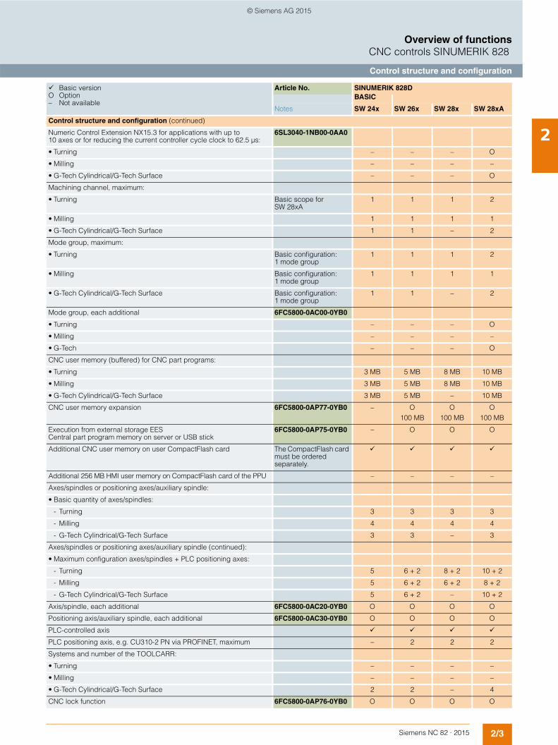
2Control structure and configuration (continued)
Numeric Control Extension NX15.3 for applications with up to 10 axes or for reducing the current controller cycle clock to 62.5 µs:
6SL3040-1NB00-0AA0
• Turning – – – O
• Milling – – – –
• G-Tech Cylindrical/G-Tech Surface – – – O
Machining channel, maximum:
• Turning Basic scope for SW 28xA
1 1 1 2
• Milling 1 1 1 1
• G-Tech Cylindrical/G-Tech Surface 1 1 – 2
Mode group, maximum:
• Turning Basic configuration: 1 mode group
1 1 1 2
• Milling Basic configuration: 1 mode group
1 1 1 1
• G-Tech Cylindrical/G-Tech Surface Basic configuration: 1 mode group
1 1 – 2
Mode group, each additional 6FC5800-0AC00-0YB0
• Turning – – – O
• Milling – – – –
• G-Tech – – – O
CNC user memory (buffered) for CNC part programs:
• Turning 3 MB 5 MB 8 MB 10 MB
• Milling 3 MB 5 MB 8 MB 10 MB
• G-Tech Cylindrical/G-Tech Surface 3 MB 5 MB – 10 MB
CNC user memory expansion 6FC5800-0AP77-0YB0 – O100 MB
O100 MB
O100 MB
Execution from external storage EES Central part program memory on server or USB stick
6FC5800-0AP75-0YB0 – O O O
Additional CNC user memory on user CompactFlash card The CompactFlash card must be ordered separately.
Additional 256 MB HMI user memory on CompactFlash card of the PPU – – – –
Axes/spindles or positioning axes/auxiliary spindle:
• Basic quantity of axes/spindles:
- Turning 3 3 3 3
- Milling 4 4 4 4
- G-Tech Cylindrical/G-Tech Surface 3 3 – 3
Axes/spindles or positioning axes/auxiliary spindle (continued):
• Maximum configuration axes/spindles + PLC positioning axes:
- Turning 5 6 + 2 8 + 2 10 + 2
- Milling 5 6 + 2 6 + 2 8 + 2
- G-Tech Cylindrical/G-Tech Surface 5 6 + 2 – 10 + 2
Axis/spindle, each additional 6FC5800-0AC20-0YB0 O O O O
Positioning axis/auxiliary spindle, each additional 6FC5800-0AC30-0YB0 O O O O
PLC-controlled axis
PLC positioning axis, e.g. CU310-2 PN via PROFINET, maximum – 2 2 2
Systems and number of the TOOLCARR:
• Turning – – – –
• Milling – – – –
• G-Tech Cylindrical/G-Tech Surface 2 2 – 4
CNC lock function 6FC5800-0AP76-0YB0 O O O O
Basic version O Option – Not available
Article No. SINUMERIK 828DBASIC
Notes SW 24x SW 26x SW 28x SW 28xA
© Siemens AG 2015
2/4 Siemens NC 82 · 2015
Overview of functionsCNC controls SINUMERIK 828
Connectable drives
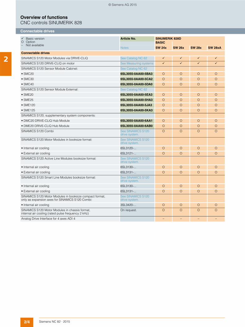
2Connectable drives
SINAMICS S120 Motor Modules via DRIVE-CLiQ See Catalog NC 62
SINAMICS S120 DRIVE-CLiQ on motor See Measuring systems
SINAMICS S120 Sensor Module Cabinet: See Catalog NC 62
• SMC20 6SL3055-0AA00-5BA3 O O O O
• SMC30 6SL3055-0AA00-5CA2 O O O O
• SMC40 6SL3055-0AA00-5DA0 O O O O
SINAMICS S120 Sensor Module External: See Catalog NC 62
• SME20 6SL3055-0AA00-5EA3 O O O O
• SME25 6SL3055-0AA00-5HA3 O O O O
• SME120 6SL3055-0AA00-5JA3 O O O O
• SME125 6SL3055-0AA00-5KA3 O O O O
SINAMICS S120, supplementary system components:
• DMC20 DRIVE-CLiQ Hub Module 6SL3055-0AA00-6AA1 O O O O
• DME20 DRIVE-CLiQ Hub Module 6SL3055-0AA00-6AB0 O O O O
SINAMICS S120 Combi See SINAMICS S120 drive system.
O O O O
SINAMICS S120 Motor Modules in booksize format: See SINAMICS S120 drive system.
• Internal air cooling 6SL3120-... O O O O
• External air cooling 6SL3121-... O O O O
SINAMICS S120 Active Line Modules booksize format: See SINAMICS S120 drive system.
• Internal air cooling 6SL3130-... O O O O
• External air cooling 6SL3131-... O O O O
SINAMICS S120 Smart Line Modules booksize format: See SINAMICS S120 drive system.
• Internal air cooling 6SL3130-... O O O O
• External air cooling 6SL3131-... O O O O
SINAMICS S120 Motor Modules in booksize compact format, only as expansion axes for SINAMICS S120 Combi:
See SINAMICS S120 drive system.
• Internal air cooling 3SL3420-... O O O O
SINAMICS S120 Motor Modules in chassis format, internal air cooling (rated pulse frequency 2 kHz)
On request. O O O O
Analog Drive Interface for 4 axes ADI 4 – – – –
Basic version O Option – Not available
Article No. SINUMERIK 828DBASIC
Notes SW 24x SW 26x SW 28x SW 28xA
© Siemens AG 2015
2/5Siemens NC 82 · 2015
Overview of functionsCNC controls SINUMERIK 828
Connectable measuring systems/Connectable motors
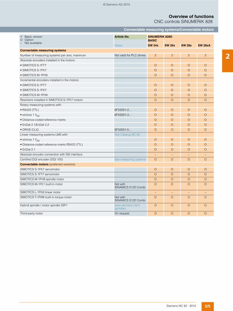
2Connectable measuring systems
Number of measuring systems per axis, maximum Not valid for PLC drives. 2 2 2 2
Absolute encoders installed in the motors:
• SIMOTICS S-1FT7 O O O O
• SIMOTICS S-1FK7 O O O O
• SIMOTICS M-1PH8 O O O O
Incremental encoders installed in the motors:
• SIMOTICS S-1FT7 O O O O
• SIMOTICS S-1FK7 O O O O
• SIMOTICS M-1PH8 O O O O
Resolvers installed in SIMOTICS S-1FK7 motors O O O O
Rotary measuring systems with:
• RS422 (TTL) 6FX2001-2... O O O O
• sin/cos 1 Vpp 6FX2001-3... O O O O
• Distance-coded reference marks O O O O
• EnDat 2.1/EnDat 2.2 O O O O
• DRIVE-CLiQ 6FX2001-5... O O O O
Linear measuring systems LMS with: See Catalog NC 62
• sin/cos 1 Vpp O O O O
• Distance-coded reference marks RS422 (TTL) O O O O
• EnDat 2.1 O O O O
Absolute encoder connection with SSI interface – – – –
Certified DQI encoder (DQI 100) See measuring systems O O O O
Connectable motors (preferred versions)
SIMOTICS S-1FK7 servomotor O O O O
SIMOTICS S-1FT7 servomotor O O O O
SIMOTICS M-1PH8 spindle motor O O O O
SIMOTICS M-1FE1 built-in motor Not with SINAMICS S120 Combi.
O O O O
SIMOTICS L-1FN3 linear motor – – – –
SIMOTICS T-1FW6 built-in torque motor Not with SINAMICS S120 Combi.
O O O O
Hybrid spindle / motor spindle 2SP1 www.siemens.com/spindles
O O O O
Third-party motor On request. O O O O
Basic version O Option – Not available
Article No. SINUMERIK 828DBASIC
Notes SW 24x SW 26x SW 28x SW 28xA
© Siemens AG 2015

2/6 Siemens NC 82 · 2015
Overview of functionsCNC controls SINUMERIK 828
Axis functions/Spindle functions
2Axis functions
Feedrate override 0 ... 200 % 0 ... 200 % 0 ... 200 % 0 ... 200 %
Feedrate override, axis-specific 0 ... 200 % 0 ... 200 % 0 ... 200 % 0 ... 200 %
Traversing range, decades ± 9 ± 9 ± 9 ± 9
Rotary axis, turning endlessly
Velocity, maximum 300 m/s 300 m/s 300 m/s 300 m/s
Acceleration with jerk limitation
Programmable acceleration
Follow-up mode
Measuring systems 1 and 2, selectable
Feedrate interpolation
Separate feedrate for roundings and chamfers
Travel to fixed stop
Travel to fixed stop with Force Control 6FC5800-0AM01-0YB0 O O O O
Analog axis – – – –
Setpoint exchange – – – –
Tangential control 6FC5800-0AM06-0YB0
• Turning – – – –
• Milling – – – –
• G-Tech Cylindrical/G-Tech Surface O O – O
Position switching signals/cam controller – – – –
Advanced Position Control APC – – – –
Spindle functions
Spindle speed, analog setpoint
Spindle speed, digital setpoint
Spindle speed, max. programmable value range Display: ± 999999999.9999
106 ... 10-4 106 ... 10-4 106 ... 10-4 106 ... 10-4
Spindle override 0 ... 200 % 0 ... 200 % 0 ... 200 % 0 ... 200 %
Gear stages 5 5 5 5
Intermediate gear
Gear stage selection, automatic
Oriented spindle stop
Spindle speed limitation min./max.
Constant cutting rate
Spindle control via PLC (positioning, oscillation)
Changeover to axis mode
Axis synchronization on-the-fly
Thread run-in and run-out, programmable
Thread cutting with constant or variable pitch
Tapping with compensating chuck/rigid tapping
Basic version O Option – Not available
Article No. SINUMERIK 828DBASIC
Notes SW 24x SW 26x SW 28x SW 28xA
© Siemens AG 2015

2/7Siemens NC 82 · 2015
Overview of functionsCNC controls SINUMERIK 828
Interpolations/Couplings
2Interpolations
Linear interpolating axes, maximum 4 4 4 4
Circle via center point and end point
Circle via interpolation point
Helical interpolation
Universal interpolator NURBS (non-uniform rational B splines)
Continuous-path mode with programmable rounding clearance
Multi-axis interpolation > 4 interpolating axes – – – –
Advanced Surface: 6FC5800-0AS07-0YB0
• Turning – – – –
• Milling
• G-Tech Cylindrical/G-Tech Surface O O – O
Spline interpolation (A, B and C splines) 6FC5800-0AS16-0YB0 O O O O
Compressor for 3-axis machining COMPCAD
• Turning – – – –
• Milling
• G-Tech Cylindrical/G-Tech Surface –
Polynomial interpolation – – – –
Involute interpolation – – – –
Crank interpolation CRIP – – – –
Couplings
Pair of synchronized axes (gantry axes), Basic 6FC5800-0AS51-0YB0 O O O O
• Turning 1 1 1 1
• Milling 1 1 1 2
• G-Tech Cylindrical/G-Tech Surface 1 1 – 1
Master-Slave for drives, basic 6FC5800-0AS52-0YB0 O O O O
Generic coupling static, CP-Static, e.g. counterspindle: 6FC5800-0AM75-0YB0
• 1 × simple synchronous spindle, coupling ratio 1:1, no multi-edge machining
- Turning – – O O
- Milling O O O O
- G-Tech Cylindrical/G-Tech Surface O O – O
Generic coupling basic, CP-Basic, e.g. multi-edge turning: 6FC5800-0AM72-0YB0
• 4 axis pairs in simultaneous coupled motion
- Turning O O O O
- Milling – – – –
- G-Tech Cylindrical/G-Tech Surface O O – O
• 1 × synchronous spindle/multi-edge turning
- Turning O O O O
- Milling – – – –
- G-Tech Cylindrical/G-Tech Surface O O – O
• Master-value coupling/curve table interpolation – – – –
Basic version O Option – Not available
Article No. SINUMERIK 828DBASIC
Notes SW 24x SW 26x SW 28x SW 28xA
© Siemens AG 2015
2/8 Siemens NC 82 · 2015
Overview of functionsCNC controls SINUMERIK 828
Couplings/Transformations
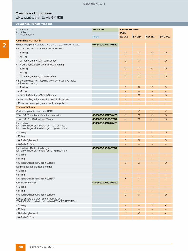
2Couplings (continued)
Generic coupling Comfort, CP-Comfort, e.g. electronic gear: 6FC5800-0AM73-0YB0
• 4 axis pairs in simultaneous coupled motion:
- Turning O O O O
- Milling – – – –
- G-Tech Cylindrical/G-Tech Surface O O – O
• 1 x synchronous spindle/multi-edge turning:
- Turning O O O O
- Milling – – – –
- G-Tech Cylindrical/G-Tech Surface O O – O
• Electronic gear for 3 leading axes, without curve table, without cascading:
- Turning O O O O
- Milling – – – –
- G-Tech Cylindrical/G-Tech Surface O O – O
• Axial coupling in the machine coordinate system – – – –
• Master-value coupling/curve table interpolation – – – –
Transformations
Cartesian point-to-point travel PTP
TRANSMIT/cylinder surface transformation 6FC5800-0AM27-0YB0 O O O O
TRANSMIT/TRACYL without Y axis 6FC5800-0AS50-0YB0 O O O O
Inclined axisfor non-orthogonal Y axis for turning machinesfor non-orthogonal X axis for grinding machines:
6FC5800-0AM28-0YB0
• Turning – – O O
• Milling – – – –
• G-Tech Cylindrical O O – O
• G-Tech Surface – – – –
Inclined axis Basic, fixed angle for non-orthogonal X axis for grinding machines:
6FC5800-0AS54-0YB0
• Turning – – – –
• Milling – – – –
• G-Tech Cylindrical/G-Tech Surface O O – O
Simple oscillation function, modal
• Turning – – – –
• Milling – – – –
• G-Tech Cylindrical/G-Tech Surface –
Oscillation function: 6FC5800-0AM34-0YB0
• Turning – – – –
• Milling – – – –
• G-Tech Cylindrical/G-Tech Surface O O – O
Concatenated transformations inclined axis TRAANG after cardanic milling head/TRANSMIT/TRACYL:
• Turning – –
• Milling – – – –
• G-Tech Cylindrical –
• G-Tech Surface – – – –
Basic version O Option – Not available
Article No. SINUMERIK 828DBASIC
Notes SW 24x SW 26x SW 28x SW 28xA
© Siemens AG 2015
2/9Siemens NC 82 · 2015
Overview of functionsCNC controls SINUMERIK 828
Measuring functions and measuring cycles/Technologies
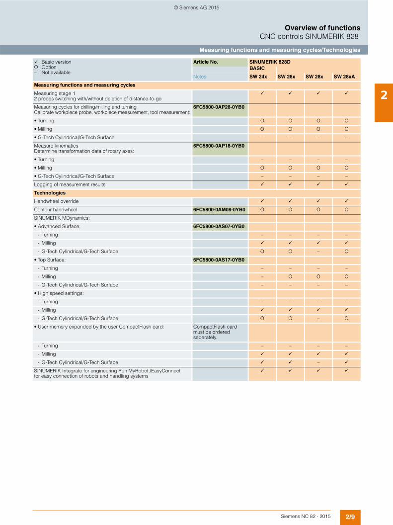
2Measuring functions and measuring cycles
Measuring stage 1 2 probes switching with/without deletion of distance-to-go
Measuring cycles for drilling/milling and turning Calibrate workpiece probe, workpiece measurement, tool measurement:
6FC5800-0AP28-0YB0
• Turning O O O O
• Milling O O O O
• G-Tech Cylindrical/G-Tech Surface – – – –
Measure kinematics Determine transformation data of rotary axes:
6FC5800-0AP18-0YB0
• Turning – – – –
• Milling O O O O
• G-Tech Cylindrical/G-Tech Surface – – – –
Logging of measurement results
Technologies
Handwheel override
Contour handwheel 6FC5800-0AM08-0YB0 O O O O
SINUMERIK MDynamics:
• Advanced Surface: 6FC5800-0AS07-0YB0
- Turning – – – –
- Milling
- G-Tech Cylindrical/G-Tech Surface O O – O
• Top Surface: 6FC5800-0AS17-0YB0
- Turning – – – –
- Milling – O O O
- G-Tech Cylindrical/G-Tech Surface – – – –
• High speed settings:
- Turning – – – –
- Milling
- G-Tech Cylindrical/G-Tech Surface O O – O
• User memory expanded by the user CompactFlash card: CompactFlash card must be ordered separately.
- Turning – – – –
- Milling
- G-Tech Cylindrical/G-Tech Surface –
SINUMERIK Integrate for engineering Run MyRobot /EasyConnect for easy connection of robots and handling systems
Basic version O Option – Not available
Article No. SINUMERIK 828DBASIC
Notes SW 24x SW 26x SW 28x SW 28xA
© Siemens AG 2015

2/10 Siemens NC 82 · 2015
Overview of functionsCNC controls SINUMERIK 828
Motion-synchronous actions/Engineering
2Motion-synchronous actions
CNC inputs/outputs, high-speed:
• Digital inputs drives onboard 12 12 12 12
• Digital inputs or outputs drives onboard, parameterizable 8 8 8 8
• Digital inputs CNC onboard 8 8 8 8
• Digital outputs CNC onboard 8 8 8 8
Synchronized actions and fast auxiliary function output incl. 3 synchronous functions
Positioning axes and spindles via synchronized actions (command axes)
Analog value control in the interpolation cycle – – – –
Evaluation of internal drive variables, basic 6FC5800-0AS53-0YB0 O O O O
Asynchronous subprograms ASUB
Interrupt routines with fast retraction from the contour (with subprogram/ASUB)
Cross-mode actions (ASUBs and synchronized actions in all operating modes)
Display active synchronized actions in HMI: Included in option: Extended operator functions. 6FC5800-0AP16-0YB0
• Turning O O O
• Milling O O O
• G-Tech Cylindrical/G-Tech Surface O O –
Engineering
OA Easy Screen:
• Free screens 5 5 5 5
SINUMERIK Operate Runtime license OA Easy ScreenSINUMERIK Integrate for engineering Run MyScreens:
• > 5 screens, extended functions 6FC5800-0AP64-0YB0 O O O O
Basic version O Option – Not available
Article No. SINUMERIK 828DBASIC
Notes SW 24x SW 26x SW 28x SW 28xA
© Siemens AG 2015

2/11Siemens NC 82 · 2015
Overview of functionsCNC controls SINUMERIK 828
CNC programming language
2CNC programming language
Programming language DIN 66025 and high-level language expansion
Main program call from main program and subprogram
Subroutine levels, maximum 11 11 11 11
Interrupt routines, maximum 4 4 4 4
Number of subprogram passes ≤ 9999 ≤ 9999 ≤ 9999 ≤ 9999
Number of levels for skip blocks 2 2 2 2
Number of levels for skip blocks, maximum: Included in option: Extended operator functions6FC5800-0AP16-0YB0
10 10 10 10
• Turning O O O
• Milling O O O
• G-Tech Cylindrical/G-Tech Surface O O –
Polar coordinates
1/2/3-point contours
Dimensions metric/inch, changeover via operator action or program
Inverse-time feedrate
Auxiliary function output via:
• M word, max. programmable value range: INT 231 -1 ... 231
• H word, max. programmable value range: REAL ± 3.4028 ex38, INT -231 ... 231 -1
Display:± 999999999.9999
CNC high-level language with:
• User variables, GUD, configurable
• Predefined user variables (R parameters), commentable 300 300 300 300
• Predefined global user variables (global R parameters), commentable
- Turning – – – 100
- Milling – – – –
- G-Tech Cylindrical/G-Tech Surface – – – 100
• Predefined user variables LUD (R parameters), configurable
• Read/write system variables
• Indirect programming
• Program jumps and branches
• Program coordination with WAIT, START, INIT
- Turning – – –
- Milling – – – –
- G-Tech Cylindrical/G-Tech Surface – – –
• Arithmetic and trigonometric functions
• Comparison operations and logic combinations
• Macro techniques
• Control structures IF-ELSE-ENDIF
• Control structures WHILE, FOR, REPEAT, LOOP
• Commands to HMI
• STRING functions
Basic version O Option – Not available
Article No. SINUMERIK 828DBASIC
Notes SW 24x SW 26x SW 28x SW 28xA
© Siemens AG 2015
2/12 Siemens NC 82 · 2015
Overview of functionsCNC controls SINUMERIK 828
CNC programming language
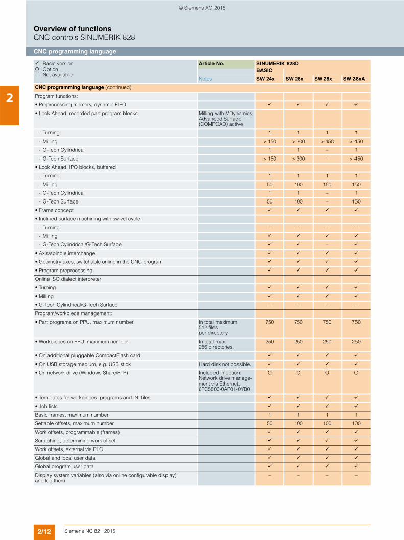
2CNC programming language (continued)
Program functions:
• Preprocessing memory, dynamic FIFO
• Look Ahead, recorded part program blocks Milling with MDynamics,Advanced Surface (COMPCAD) active
- Turning 1 1 1 1
- Milling > 150 > 300 > 450 > 450
- G-Tech Cylindrical 1 1 – 1
- G-Tech Surface > 150 > 300 – > 450
• Look Ahead, IPO blocks, buffered
- Turning 1 1 1 1
- Milling 50 100 150 150
- G-Tech Cylindrical 1 1 – 1
- G-Tech Surface 50 100 – 150
• Frame concept
• Inclined-surface machining with swivel cycle
- Turning – – – –
- Milling
- G-Tech Cylindrical/G-Tech Surface –
• Axis/spindle interchange
• Geometry axes, switchable online in the CNC program
• Program preprocessing
Online ISO dialect interpreter
• Turning
• Milling
• G-Tech Cylindrical/G-Tech Surface – – – –
Program/workpiece management:
• Part programs on PPU, maximum number In total maximum 512 files per directory.
750 750 750 750
• Workpieces on PPU, maximum number In total max. 256 directories.
250 250 250 250
• On additional pluggable CompactFlash card
• On USB storage medium, e.g. USB stick Hard disk not possible.
• On network drive (Windows Share/FTP) Included in option: Network drive manage-ment via Ethernet. 6FC5800-0AP01-0YB0
O O O O
• Templates for workpieces, programs and INI files
• Job lists
Basic frames, maximum number 1 1 1 1
Settable offsets, maximum number 50 100 100 100
Work offsets, programmable (frames)
Scratching, determining work offset
Work offsets, external via PLC
Global and local user data
Global program user data
Display system variables (also via online configurable display) and log them
– – – –
Basic version O Option – Not available
Article No. SINUMERIK 828DBASIC
Notes SW 24x SW 26x SW 28x SW 28xA
© Siemens AG 2015

2/13Siemens NC 82 · 2015
Overview of functionsCNC controls SINUMERIK 828
Programming support
2Programming support
Program editor:
• Programming support for cycles, programGUIDE
• CNC editor with editing functions: selecting, copying, deleting
• Geometry processor with programming graphics/free contour input (contour calculator)
• Screens for 1/2/3-point contours (contour definition programming) – – – –
• Machining step programming ShopTurn/ShopMill 6FC5800-0AP17-0YB0
- Turning O O O O
- Milling O O O O
- G-Tech Cylindrical/G-Tech Surface – – – –
• programSYNC – multi-channel step sequence programming 6FC5800-0AP05-0YB0
- Turning – – – O
- Milling – – – –
- G-Tech Cylindrical/G-Tech Surface – – – –
• Manual machine functions Included in option: Machining step programming ShopTurn/ShopMill6FC5800-0AP17-0YB0
- Turning O O O O
- Milling O O O O
- G-Tech Cylindrical/G-Tech Surface – – – –
• Backup workpiece setup data Included in option: Extended operator functions6FC5800-0AP16-0YB0
- Turning O O O
- Milling O O O
- G-Tech Cylindrical/G-Tech Surface O O –
• Multiple clamping of various workpieces Included in option: Machining step programming ShopTurn/ShopMill6FC5800-0AP17-0YB0
- Turning – – – –
- Milling O O O O
- G-Tech Cylindrical/G-Tech Surface – – – –
Basic version O Option – Not available
Article No. SINUMERIK 828DBASIC
Notes SW 24x SW 26x SW 28x SW 28xA
© Siemens AG 2015
2/14 Siemens NC 82 · 2015
Overview of functionsCNC controls SINUMERIK 828
Programming support
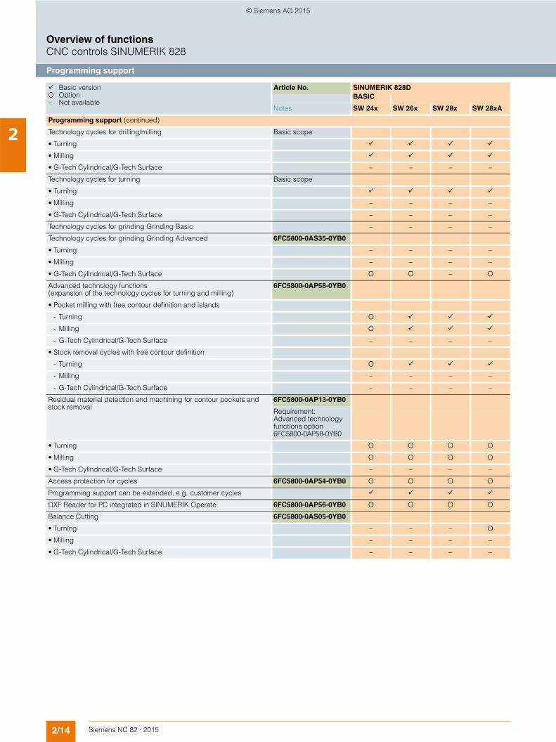
2Programming support (continued)
Technology cycles for drilling/milling Basic scope
• Turning
• Milling
• G-Tech Cylindrical/G-Tech Surface – – – –
Technology cycles for turning Basic scope
• Turning
• Milling – – – –
• G-Tech Cylindrical/G-Tech Surface – – – –
Technology cycles for grinding Grinding Basic – – – –
Technology cycles for grinding Grinding Advanced 6FC5800-0AS35-0YB0
• Turning – – – –
• Milling – – – –
• G-Tech Cylindrical/G-Tech Surface O O – O
Advanced technology functions (expansion of the technology cycles for turning and milling)
6FC5800-0AP58-0YB0
• Pocket milling with free contour definition and islands
- Turning O
- Milling O
- G-Tech Cylindrical/G-Tech Surface – – – –
• Stock removal cycles with free contour definition
- Turning O
- Milling – – – –
- G-Tech Cylindrical/G-Tech Surface – – – –
Residual material detection and machining for contour pockets and stock removal
6FC5800-0AP13-0YB0
Requirement: Advanced technology functions option6FC5800-0AP58-0YB0
• Turning O O O O
• Milling O O O O
• G-Tech Cylindrical/G-Tech Surface – – – –
Access protection for cycles 6FC5800-0AP54-0YB0 O O O O
Programming support can be extended, e.g. customer cycles
DXF Reader for PC integrated in SINUMERIK Operate 6FC5800-0AP56-0YB0 O O O O
Balance Cutting 6FC5800-0AS05-0YB0
• Turning – – – O
• Milling – – – –
• G-Tech Cylindrical/G-Tech Surface – – – –
Basic version O Option – Not available
Article No. SINUMERIK 828DBASIC
Notes SW 24x SW 26x SW 28x SW 28xA
© Siemens AG 2015

2/15Siemens NC 82 · 2015
Overview of functionsCNC controls SINUMERIK 828
Simulations/Operating modes
2Simulations
Simulation of program X, while program Y is being executed (simulation parallel to machining)
– – – –
Simulation finished part in 2D representation
Simulation 1 finished part in 3D representation 6FC5800-0AP25-0YB0
• Turning O O O O
• Milling O O O O
• G-Tech Cylindrical/G-Tech Surface – – – –
Simulation finished part and working area in 3D representation – – – –
Simulation finished part with collision check in 3D representation – – – –
Simultaneous recording Real-time simulation of current machining operation
6FC5800-0AP22-0YB0 O O O O
Operating modes
JOG:
• Handwheel selection
• Inch/metric changeover
• Manual measurement of work offset
- Turning
- Milling
- G-Tech Cylindrical/G-Tech Surface – – – –
• Additional measuring version via standard scope- Standard scope workpiece zero: Set edge, align edge, right-angled
corner, 1 hole, and 1 circular spigot and rectangular spigot- Expansion of the measurement masks via combo box
Included in option: Extended operator functions. 6FC5800-0AP16-0YB0
- Turning – – – –
- Milling O O O
- G-Tech Cylindrical/G-Tech Surface – – – –
• Manual measurement of tool offset
- Turning
- Milling
- G-Tech Cylindrical/G-Tech Surface – – – –
• Automatic tool/workpiece measurement
- Turning
- Milling
- G-Tech Cylindrical/G-Tech Surface – – – –
• Reference point approach, automatic/via CNC program
MDI:
• Input in text editor
• Load/save MDI program Included in option: Extended operator functions. 6FC5800-0AP16-0YB0
- Turning O O O
- Milling O O O
- G-Tech Cylindrical/G-Tech Surface O O –
• Input screen forms for technology and positioning, cycle support
Basic version O Option – Not available
Article No. SINUMERIK 828DBASIC
Notes SW 24x SW 26x SW 28x SW 28xA
© Siemens AG 2015

2/16 Siemens NC 82 · 2015
Overview of functionsCNC controls SINUMERIK 828
Operating modes
2Operating modes (continued)
Teach-in: Included in option: Extended operator functions. 6FC5800-0AP16-0YB0
• Turning O O O
• Milling O O O
• G-Tech Cylindrical/G-Tech Surface O O –
Automatic:
• Execution from storage medium connected to CompactFlash card interface on the operator panel front
• Execution from storage medium connected to the front USB interface of the operator panel, e.g. card reader, USB stick
Hard disk not possible.
• Execution from storage medium connected to the rear USB interface of the operator panel, e.g. card reader, USB stick
Hard disk not possible.
• Execution from network drive Included in option: Network drive manage-ment via Ethernet. 6FC5800-0AP01-0YB0
O O O O
• Program control
• Program editing
• Overstoring Included in option: Extended operator functions. 6FC5800-0AP16-0YB0
- Turning O O O
- Milling O O O
- G-Tech Cylindrical/G-Tech Surface O O –
• DRF offset Included in option: Extended operator functions. 6FC5800-0AP16-0YB0
- Turning O O O
- Milling O O O
- G-Tech Cylindrical/G-Tech Surface O O –
• Block search with/without calculation
• Extended block search program, search point, step up and down, interrupt function
Included in option: Extended operator functions. 6FC5800-0AP16-0YB0
- Turning O O O
- Milling O O O
- G-Tech Cylindrical/G-Tech Surface O O –
Repos (repositioning on the contour):
• With operator command/semi-automatically
• Program-controlled
Preset:
• Set actual value
Basic version O Option – Not available
Article No. SINUMERIK 828DBASIC
Notes SW 24x SW 26x SW 28x SW 28xA
© Siemens AG 2015
2/17Siemens NC 82 · 2015
Overview of functionsCNC controls SINUMERIK 828
Tools
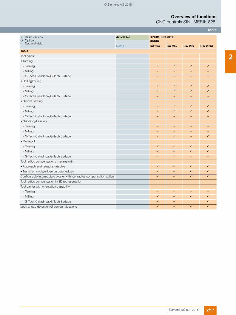
2Tools
Tool types:
• Turning
- Turning
- Milling – – – –
- G-Tech Cylindrical/G-Tech Surface – – – –
• Drilling/milling
- Turning
- Milling
- G-Tech Cylindrical/G-Tech Surface – – – –
• Groove sawing
- Turning
- Milling
- G-Tech Cylindrical/G-Tech Surface – – – –
• Grinding/dressing
- Turning – – – –
- Milling – – – –
- G-Tech Cylindrical/G-Tech Surface –
• Multi-tool
- Turning
- Milling
- G-Tech Cylindrical/G-Tech Surface – – – –
Tool radius compensations in plane with:
• Approach and retract strategies
• Transition circle/ellipse on outer edges
Configurable intermediate blocks with tool radius compensation active
Tool radius compensation in 3D representation – – – –
Tool carrier with orientation capability
- Turning – – – –
- Milling
- G-Tech Cylindrical/G-Tech Surface –
Look-ahead detection of contour violations
Basic version O Option – Not available
Article No. SINUMERIK 828DBASIC
Notes SW 24x SW 26x SW 28x SW 28xA
© Siemens AG 2015

2/18 Siemens NC 82 · 2015
Overview of functionsCNC controls SINUMERIK 828
Tool management
2Tool management
Operation with tool management:
• Real magazines, maximum number
- Turning 1 1 2 2
- Milling 1 1 2 2
- G-Tech Cylindrical/G-Tech Surface 1 2 – 2
• Tool list
• Expandable tool list – – – –
• Tools in tool list
- Turning 128 256 512 768
- Milling 128 256 512 768
- G-Tech Cylindrical/G-Tech Surface 128 256 – 768
• Cutting edges in tool list
- Turning 256 512 1024 1536
- Milling 256 512 1024 1536
- G-Tech Cylindrical/G-Tech Surface 256 512 – 1536
• Tool offset selection via T and D numbers
• Magazine list
• Configurable magazine list
• Magazine data
• Empty location search and place positioning
• Easy empty location search using softkeys
• Loading and unloading of tools
• Tool cabinet and tool catalog – – – –
• Loading and unloading via code carrier system – – – –
• Adapter data
- Turning
- Milling – – – –
- G-Tech Cylindrical/G-Tech Surface – –
• Location-dependent offsets, reference point on disk
- Turning – – – –
- Milling – – – –
- G-Tech Cylindrical/G-Tech Surface –
• Tool life monitoring and workpiece count
• Replacement tools for tool management 6FC5800-0AM78-0YB0
- Turning O O O
- Milling O O O
- G-Tech Cylindrical/G-Tech Surface – – – –
• Multi-tool tool holder – – – –
Manage toolsSINUMERIK Integrate for production Manage MyTools
– – – –
Basic version O Option – Not available
Article No. SINUMERIK 828DBASIC
Notes SW 24x SW 26x SW 28x SW 28xA
© Siemens AG 2015
2/19Siemens NC 82 · 2015
Overview of functionsCNC controls SINUMERIK 828
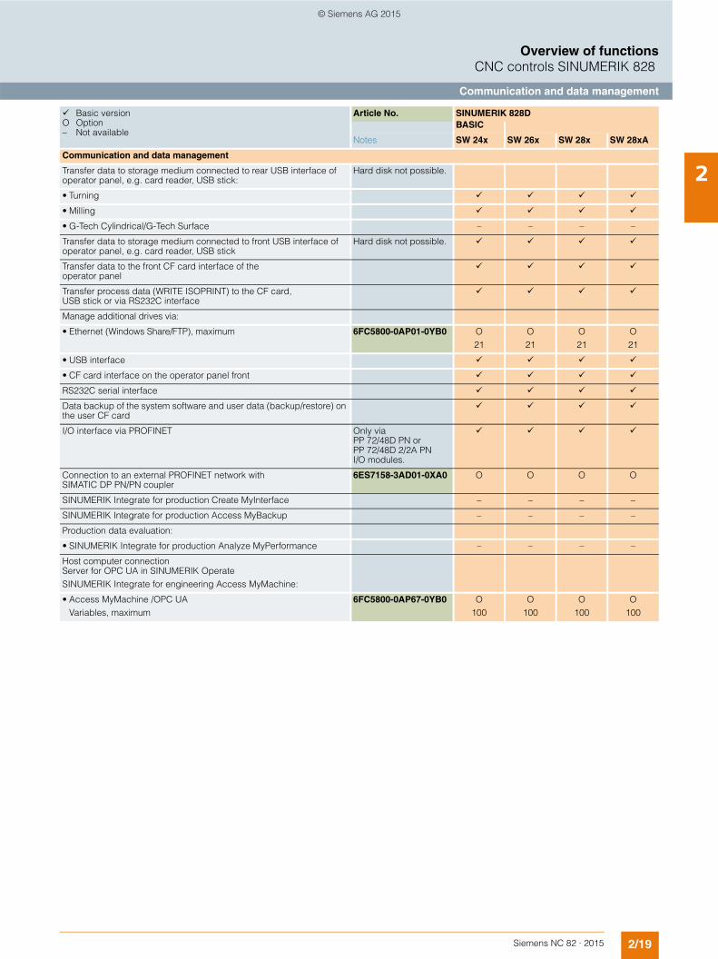
Communication and data management
2Communication and data management
Transfer data to storage medium connected to rear USB interface of operator panel, e.g. card reader, USB stick:
Hard disk not possible.
• Turning
• Milling
• G-Tech Cylindrical/G-Tech Surface – – – –
Transfer data to storage medium connected to front USB interface of operator panel, e.g. card reader, USB stick
Hard disk not possible.
Transfer data to the front CF card interface of the operator panel
Transfer process data (WRITE ISOPRINT) to the CF card, USB stick or via RS232C interface
Manage additional drives via:
• Ethernet (Windows Share/FTP), maximum 6FC5800-0AP01-0YB0 O21
O21
O21
O21
• USB interface
• CF card interface on the operator panel front
RS232C serial interface
Data backup of the system software and user data (backup/restore) on the user CF card
I/O interface via PROFINET Only via PP 72/48D PN or PP 72/48D 2/2A PN I/O modules.
Connection to an external PROFINET network with SIMATIC DP PN/PN coupler
6ES7158-3AD01-0XA0 O O O O
SINUMERIK Integrate for production Create MyInterface – – – –
SINUMERIK Integrate for production Access MyBackup – – – –
Production data evaluation:
• SINUMERIK Integrate for production Analyze MyPerformance – – – –
Host computer connection Server for OPC UA in SINUMERIK OperateSINUMERIK Integrate for engineering Access MyMachine:
• Access MyMachine /OPC UAVariables, maximum
6FC5800-0AP67-0YB0 O100
O100
O100
O100
Basic version O Option – Not available
Article No. SINUMERIK 828DBASIC
Notes SW 24x SW 26x SW 28x SW 28xA
© Siemens AG 2015
2/20 Siemens NC 82 · 2015
Overview of functionsCNC controls SINUMERIK 828
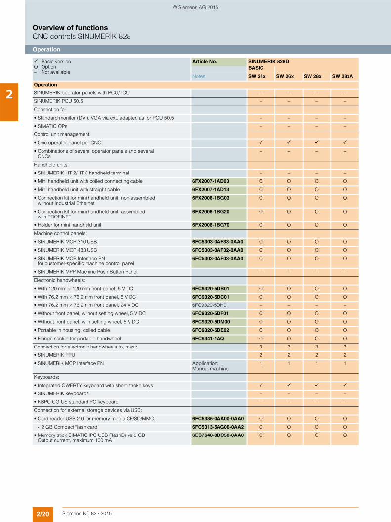
Operation
2Operation
SINUMERIK operator panels with PCU/TCU – – – –
SINUMERIK PCU 50.5 – – – –
Connection for:
• Standard monitor (DVI), VGA via ext. adapter, as for PCU 50.5 – – – –
• SIMATIC OPs – – – –
Control unit management:
• One operator panel per CNC
• Combinations of several operator panels and several CNCs
– – – –
Handheld units:
• SINUMERIK HT 2/HT 8 handheld terminal – – – –
• Mini handheld unit with coiled connecting cable 6FX2007-1AD03 O O O O
• Mini handheld unit with straight cable 6FX2007-1AD13 O O O O
• Connection kit for mini handheld unit, non-assembled without Industrial Ethernet
6FX2006-1BG03 O O O O
• Connection kit for mini handheld unit, assembled with PROFINET
6FX2006-1BG20 O O O O
• Holder for mini handheld unit 6FX2006-1BG70 O O O O
Machine control panels:
• SINUMERIK MCP 310 USB 6FC5303-0AF33-0AA0 O O O O
• SINUMERIK MCP 483 USB 6FC5303-0AF32-0AA0 O O O O
• SINUMERIK MCP Interface PN for customer-specific machine control panel
6FC5303-0AF03-0AA0 O O O O
• SINUMERIK MPP Machine Push Button Panel – – – –
Electronic handwheels:
• With 120 mm × 120 mm front panel, 5 V DC 6FC9320-5DB01 O O O O
• With 76.2 mm × 76.2 mm front panel, 5 V DC 6FC9320-5DC01 O O O O
• With 76.2 mm × 76.2 mm front panel, 24 V DC 6FC9320-5DH01 – – – –
• Without front panel, without setting wheel, 5 V DC 6FC9320-5DF01 O O O O
• Without front panel, with setting wheel, 5 V DC 6FC9320-5DM00 O O O O
• Portable in housing, coiled cable 6FC9320-5DE02 O O O O
• Flange socket for portable handwheel 6FC9341-1AQ O O O O
Connection for electronic handwheels to, max.: 3 3 3 3
• SINUMERIK PPU 2 2 2 2
• SINUMERIK MCP Interface PN Application: Manual machine
1 1 1 1
Keyboards:
• Integrated QWERTY keyboard with short-stroke keys
• SINUMERIK keyboards – – – –
• KBPC CG US standard PC keyboard – – – –
Connection for external storage devices via USB:
• Card reader USB 2.0 for memory media CF/SD/MMC: 6FC5335-0AA00-0AA0 O O O O
- 2 GB CompactFlash card 6FC5313-5AG00-0AA2 O O O O
• Memory stick SIMATIC IPC USB FlashDrive 8 GB Output current, maximum 100 mA
6ES7648-0DC50-0AA0 O O O O
Basic version O Option – Not available
Article No. SINUMERIK 828DBASIC
Notes SW 24x SW 26x SW 28x SW 28xA
© Siemens AG 2015
2/21Siemens NC 82 · 2015
Overview of functionsCNC controls SINUMERIK 828
Operation/Monitoring functions
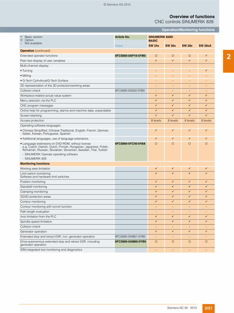
2Operation (continued)
Extended operator functions 6FC5800-0AP16-0YB0 O O O
Plain text display of user variables
Multi-channel display:
• Turning – – –
• Milling – – – –
• G-Tech Cylindrical/G-Tech Surface – – – –
2D representation of the 3D protection/working areas – – – –
Collision check 6FC5800-0AS02-0YB0 – – – –
Workpiece-related actual value system
Menu selection via the PLC
CNC program messages
Online help for programming, alarms and machine data, expandable
Screen blanking
Access protection 8 levels 8 levels 8 levels 8 levels
Operating software languages:
• Chinese Simplified, Chinese Traditional, English, French, German, Italian, Korean, Portuguese, Spanish
• Additional languages, use of language extensions
• Language extensions on DVD-ROM, without license e.g. Czech, Danish, Dutch, Finnish, Hungarian, Japanese, Polish, Romanian, Russian, Slovakian, Slovenian, Swedish, Thai, Turkish- SINUMERIK Operate operating software- SINUMERIK 828
6FC5860-0YC40-0YA8 O O O O
Monitoring functions
Working area limitation
Limit switch monitoring Software and hardware limit switches
Position monitoring
Standstill monitoring
Clamping monitoring
2D/3D protection areas
Contour monitoring
Contour monitoring with tunnel function – – – –
Path length evaluation – – – –
Axis limitation from the PLC
Spindle speed limitation
Collision check – – – –
Generator operation
Extended stop and retract ESR, incl. generator operation 6FC5800-0AM61-0YB0 – – – –
Drive-autonomous extended stop and retract ESR, including generator operation
6FC5800-0AM60-0YB0 O O O O
IDM integrated tool monitoring and diagnostics – – – –
Basic version O Option – Not available
Article No. SINUMERIK 828DBASIC
Notes SW 24x SW 26x SW 28x SW 28xA
© Siemens AG 2015
2/22 Siemens NC 82 · 2015
Overview of functionsCNC controls SINUMERIK 828
Compensations/PLC area
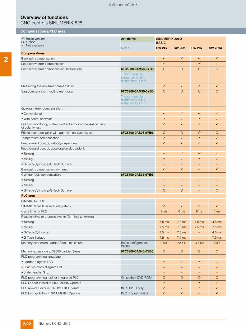
2Compensations
Backlash compensation
Leadscrew error compensation
Leadscrew error compensation, bidirectional 6FC5800-0AM54-0YB0 O O O O
The correctable tolerance band is restricted to 1 mm.
Measuring system error compensation
Sag compensation, multi-dimensional 6FC5800-0AM55-0YB0 O O O O
The correctable tolerance band is restricted to 1 mm.
Quadrant error compensation:
• Conventional
• With neural networks
Graphic monitoring of the quadrant error compensation usingcircularity test
Friction compensation with adaptive characteristics 6FC5800-0AS06-0YB0 O O O O
Temperature compensation
Feedforward control, velocity-dependent
Feedforward control, acceleration-dependent:
• Turning
• Milling
• G-Tech Cylindrical/G-Tech Surface – – – –
Backlash compensation, dynamic
Cylinder fault compensation: 6FC5800-0AS35-0YB0
• Turning – – – –
• Milling – – – –
• G-Tech Cylindrical/G-Tech Surface O O – O
PLC area
SIMATIC S7-300 – – – –
SIMATIC S7-200 based (integrated)
Cycle time for PLC 9 ms 6 ms 6 ms 6 ms
Reaction time to process events: Terminal to terminal
• Turning 7.5 ms 7.5 ms 4.5 ms 4.5 ms
• Milling 7.5 ms 7.5 ms 7.5 ms 7.5 ms
• G-Tech Cylindrical 7.5 ms 7.5 ms – 4.5 ms
• G-Tech Surface 7.5 ms 7.5 ms – 7.5 ms
Memory expansion Ladder Steps, maximum Basic configuration: 24000
32000 32000 32000 32000
Memory expansion to 32000 Ladder Steps 6FC5800-0AD40-0YB0 O O O O
PLC programming language:
• Ladder diagram LAD
• Function block diagram FBD – – – –
• Statement list STL – – – –
PLC programming tool for integrated PLC On toolbox DVD-ROM. O O O O
PLC Ladder Viewer in SINUMERIK Operate
PLC re-wire Editor in SINUMERIK Operate INT100/101 only
PLC Ladder Editor in SINUMERIK Operate PLC program editor
Basic version O Option – Not available
Article No. SINUMERIK 828DBASIC
Notes SW 24x SW 26x SW 28x SW 28xA
© Siemens AG 2015
2/23Siemens NC 82 · 2015
Overview of functionsCNC controls SINUMERIK 828
PLC area
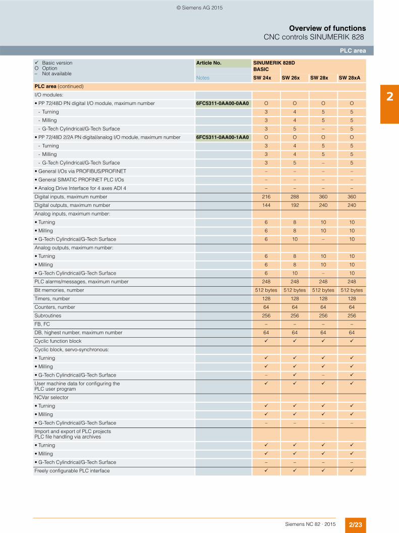
2PLC area (continued)
I/O modules:
• PP 72/48D PN digital I/O module, maximum number 6FC5311-0AA00-0AA0 O O O O
- Turning 3 4 5 5
- Milling 3 4 5 5
- G-Tech Cylindrical/G-Tech Surface 3 5 – 5
• PP 72/48D 2/2A PN digital/analog I/O module, maximum number 6FC5311-0AA00-1AA0 O O O O
- Turning 3 4 5 5
- Milling 3 4 5 5
- G-Tech Cylindrical/G-Tech Surface 3 5 – 5
• General I/Os via PROFIBUS/PROFINET – – – –
• General SIMATIC PROFINET PLC I/Os – – – –
• Analog Drive Interface for 4 axes ADI 4 – – – –
Digital inputs, maximum number 216 288 360 360
Digital outputs, maximum number 144 192 240 240
Analog inputs, maximum number:
• Turning 6 8 10 10
• Milling 6 8 10 10
• G-Tech Cylindrical/G-Tech Surface 6 10 – 10
Analog outputs, maximum number:
• Turning 6 8 10 10
• Milling 6 8 10 10
• G-Tech Cylindrical/G-Tech Surface 6 10 – 10
PLC alarms/messages, maximum number 248 248 248 248
Bit memories, number 512 bytes 512 bytes 512 bytes 512 bytes
Timers, number 128 128 128 128
Counters, number 64 64 64 64
Subroutines 256 256 256 256
FB, FC – – – –
DB, highest number, maximum number 64 64 64 64
Cyclic function block
Cyclic block, servo-synchronous:
• Turning
• Milling
• G-Tech Cylindrical/G-Tech Surface – –
User machine data for configuring the PLC user program
NCVar selector
• Turning
• Milling
• G-Tech Cylindrical/G-Tech Surface – – – –
Import and export of PLC projects PLC file handling via archives
• Turning
• Milling
• G-Tech Cylindrical/G-Tech Surface – – – –
Freely configurable PLC interface
Basic version O Option – Not available
Article No. SINUMERIK 828DBASIC
Notes SW 24x SW 26x SW 28x SW 28xA
© Siemens AG 2015
2/24 Siemens NC 82 · 2015
Overview of functionsCNC controls SINUMERIK 828
Safety functions/Commissioning
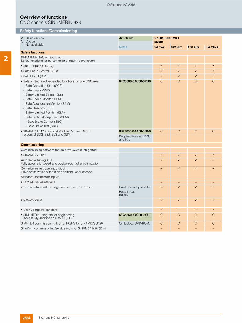
2Safety functions
SINUMERIK Safety Integrated Safety functions for personnel and machine protection:
• Safe Torque Off (STO)
• Safe Brake Control (SBC)
• Safe Stop 1 (SS1)
• Safety Integrated, extended functions for one CNC axis:- Safe Operating Stop (SOS)- Safe Stop 2 (SS2)- Safely Limited Speed (SLS)- Safe Speed Monitor (SSM)- Safe Acceleration Monitor (SAM)- Safe Direction (SDI)- Safely Limited Position (SLP)- Safe Brake Management (SBM)
- Safe Brake Control (SBC)- Safe Brake Test (SBT)
6FC5800-0AC50-0YB0 O O O O
• SINAMICS S120 Terminal Module Cabinet TM54F to control SOS, SS2, SLS and SSM
6SL3055-0AA00-3BA0 O O O O
Required for each PPU and NX.
Commissioning
Commissioning software for the drive system integrated:
• SINAMICS S120
Auto Servo Tuning ASTFully automatic speed and position controller optimization
Commissioning trace integrated Drive optimization without an additional oscilloscope
Standard commissioning via:
• RS232C serial interface – – – –
• USB interface with storage medium, e.g. USB stick Hard disk not possible.Read in/out INI file
• Network drive
• User CompactFlash card
• SINUMERIK Integrate for engineering Access MyMachine /P2P for PC/PG
6FC5860-7YC00-0YA0 O O O O
STARTER commissioning tool for PC/PG for SINAMICS S120 On toolbox DVD-ROM. O O O O
SinuCom commissioning/service tools for SINUMERIK 840D sl – – – –
Basic version O Option – Not available
Article No. SINUMERIK 828DBASIC
Notes SW 24x SW 26x SW 28x SW 28xA
© Siemens AG 2015
2/25Siemens NC 82 · 2015
Overview of functionsCNC controls SINUMERIK 828
Diagnostic functions/Service and maintenance/SINUMERIK Ctrl-Energy
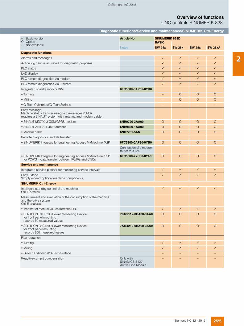
2Diagnostic functions
Alarms and messages
Action log can be activated for diagnostic purposes
PLC status
LAD display
PLC remote diagnostics via modem
PLC remote diagnostics via Ethernet
Integrated spindle monitor ISM 6FC5800-0AP55-0YB0
• Turning – O O O
• Milling – O O O
• G-Tech Cylindrical/G-Tech Surface – – – –
Easy MessageMachine status transfer using text messages (SMS) requires a SINAUT system with antenna and modem cable
• SINAUT MD720-3 GSM/GPRS modem 6NH9720-3AA00 O O O O
• SINAUT ANT 794-4MR antenna 6NH9860-1AA00 O O O O
• Modem cable 6NH7701-5AN O O O O
Remote diagnostics and file transfer:
• SINUMERIK Integrate for engineering Access MyMachine /P2P 6FC5800-0AP30-0YB0 O O O O
Connection of a modem router to X127.
• SINUMERIK Integrate for engineering Access MyMachine /P2Pfor PC/PG – data transfer between PC/PG and CNCs
6FC5860-7YC00-0YA0 O O O O
Service and maintenance
Integrated service planner for monitoring service intervals
Easy ExtendSimply extend optional machine components
SINUMERIK Ctrl-Energy
Intelligent standby control of the machine Ctrl-E profiles
Measurement and evaluation of the consumption of the machine and the drive system Ctrl-E analysis
• Transfer of manual values from the PLC
• SENTRON PAC3200 Power Monitoring Device for front panel mounting records 50 measured values
7KM2112-0BA00-3AA0 O O O O
• SENTRON PAC4200 Power Monitoring Device for front panel mounting records 200 measured values
7KM4212-0BA00-3AA0 O O O O
Flux reduction
• Turning
• Milling
• G-Tech Cylindrical/G-Tech Surface – – – –
Reactive-current compensation Only with SINAMICS S120 Active Line Module.
– – – –
Basic version O Option – Not available
Article No. SINUMERIK 828DBASIC
Notes SW 24x SW 26x SW 28x SW 28xA
© Siemens AG 2015
2/26 Siemens NC 82 · 2015
Overview of functionsCNC controls SINUMERIK 828
Industrial software for CNC/Increase service productivity
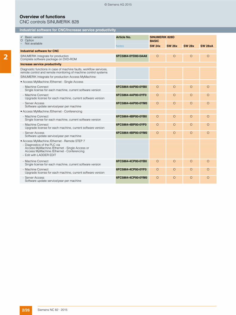
2Industrial software for CNC
SINUMERIK Integrate for production Complete software package on DVD-ROM
6FC5864-0YD00-0AA8 O O O O
Increase service productivity
Diagnostic functions in case of machine faults, workflow services, remote control and remote monitoring of machine control systemsSINUMERIK Integrate for production Access MyMachine:
• Access MyMachine /Ethernet - Single Access
- Machine ConnectSingle license for each machine, current software version
6FC5864-4AP00-0YB0 O O O O
- Machine ConnectUpgrade license for each machine, current software version
6FC5864-4AP00-0YF0 O O O O
- Server AccessSoftware update service/year per machine
6FC5864-4AP00-0YM0 O O O O
• Access MyMachine /Ethernet - Conferencing
- Machine ConnectSingle license for each machine, current software version
6FC5864-4BP00-0YB0 O O O O
- Machine ConnectUpgrade license for each machine, current software version
6FC5864-4BP00-0YF0 O O O O
- Server AccessSoftware update service/year per machine
6FC5864-4BP00-0YM0 O O O O
• Access MyMachine /Ethernet - Remote STEP 7- Diagnostics of the PLC via
Access MyMachine /Ethernet - Single Access or Access MyMachine /Ethernet - Conferencing
- Edit with LADDER EDIT
- Machine ConnectSingle license for each machine, current software version
6FC5864-4CP00-0YB0 O O O O
- Machine ConnectUpgrade license for each machine, current software version
6FC5864-4CP00-0YF0 O O O O
- Server AccessSoftware update service/year per machine
6FC5864-4CP00-0YM0 O O O O
Basic version O Option – Not available
Article No. SINUMERIK 828DBASIC
Notes SW 24x SW 26x SW 28x SW 28xA
© Siemens AG 2015
2/27Siemens NC 82 · 2015
Overview of functionsCNC controls SINUMERIK 828
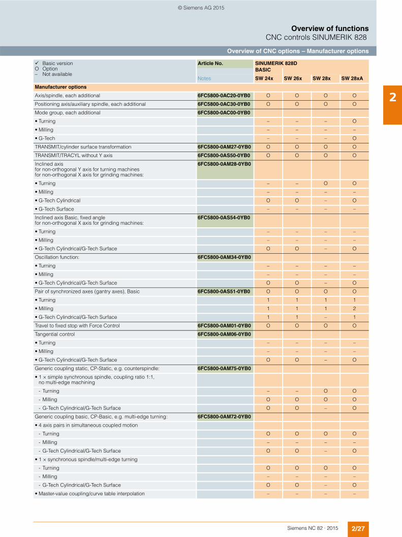
Overview of CNC options – Manufacturer options
2
Basic version O Option – Not available
Article No. SINUMERIK 828DBASIC
Notes SW 24x SW 26x SW 28x SW 28xA
Manufacturer options
Axis/spindle, each additional 6FC5800-0AC20-0YB0 O O O O
Positioning axis/auxiliary spindle, each additional 6FC5800-0AC30-0YB0 O O O O
Mode group, each additional 6FC5800-0AC00-0YB0
• Turning – – – O
• Milling – – – –
• G-Tech – – – O
TRANSMIT/cylinder surface transformation 6FC5800-0AM27-0YB0 O O O O
TRANSMIT/TRACYL without Y axis 6FC5800-0AS50-0YB0 O O O O
Inclined axisfor non-orthogonal Y axis for turning machinesfor non-orthogonal X axis for grinding machines:
6FC5800-0AM28-0YB0
• Turning – – O O
• Milling – – – –
• G-Tech Cylindrical O O – O
• G-Tech Surface – – – –
Inclined axis Basic, fixed anglefor non-orthogonal X axis for grinding machines:
6FC5800-0AS54-0YB0
• Turning – – – –
• Milling – – – –
• G-Tech Cylindrical/G-Tech Surface O O – O
Oscillation function: 6FC5800-0AM34-0YB0
• Turning – – – –
• Milling – – – –
• G-Tech Cylindrical/G-Tech Surface O O – O
Pair of synchronized axes (gantry axes), Basic 6FC5800-0AS51-0YB0 O O O O
• Turning 1 1 1 1
• Milling 1 1 1 2
• G-Tech Cylindrical/G-Tech Surface 1 1 – 1
Travel to fixed stop with Force Control 6FC5800-0AM01-0YB0 O O O O
Tangential control 6FC5800-0AM06-0YB0
• Turning – – – –
• Milling – – – –
• G-Tech Cylindrical/G-Tech Surface O O – O
Generic coupling static, CP-Static, e.g. counterspindle: 6FC5800-0AM75-0YB0
• 1 × simple synchronous spindle, coupling ratio 1:1, no multi-edge machining
- Turning – – O O
- Milling O O O O
- G-Tech Cylindrical/G-Tech Surface O O – O
Generic coupling basic, CP-Basic, e.g. multi-edge turning: 6FC5800-0AM72-0YB0
• 4 axis pairs in simultaneous coupled motion
- Turning O O O O
- Milling – – – –
- G-Tech Cylindrical/G-Tech Surface O O – O
• 1 × synchronous spindle/multi-edge turning
- Turning O O O O
- Milling – – – –
- G-Tech Cylindrical/G-Tech Surface O O – O
• Master-value coupling/curve table interpolation – – – –
© Siemens AG 2015

2/28 Siemens NC 82 · 2015
Overview of functionsCNC controls SINUMERIK 828
Overview of CNC options – Manufacturer options
2Manufacturer options (continued)
Generic coupling Comfort, CP-Comfort, e.g. electronic gear:
6FC5800-0AM73-0YB0
• 4 axis pairs in simultaneous coupled motion:
- Turning O O O O
- Milling – – – –
- G-Tech Cylindrical/G-Tech Surface O O – O
• 1 x synchronous spindle/multi-edge turning:
- Turning O O O O
- Milling – – – –
- G-Tech Cylindrical/G-Tech Surface O O – O
• Electronic gear for 3 leading axes, without curve table, without cascading:
- Turning O O O O
- Milling – – – –
- G-Tech Cylindrical/G-Tech Surface O O – O
• Axial coupling in the machine coordinate system – – – –
• Master-value coupling/curve table interpolation – – – –
Leadscrew error compensation, bidirectional 6FC5800-0AM54-0YB0 O O O O
The correctable tolerance band is restricted to 1 mm.
Sag compensation, multi-dimensional 6FC5800-0AM55-0YB0 O O O O
The correctable tolerance band is restricted to 1 mm.
Master-Slave for drives, basic 6FC5800-0AS52-0YB0 O O O O
Evaluation of internal drive variables, basic 6FC5800-0AS53-0YB0 O O O O
SINUMERIK Operate Runtime license OA Easy ScreenSINUMERIK Integrate for engineering Run MyScreens:
• > 5 screens, extended functions 6FC5800-0AP64-0YB0 O O O O
Safety Integrated extended functions for one CNC axis 6FC5800-0AC50-0YB0 O O O O
Access protection for cycles 6FC5800-0AP54-0YB0 O O O O
Drive-autonomous extended stop and retract ESR, including generator operation
6FC5800-0AM60-0YB0 O O O O
Integrated spindle monitor ISM 6FC5800-0AP55-0YB0
• Turning – O O O
• Milling – O O O
• G-Tech Cylindrical/G-Tech Surface – – – –
Collision check 6FC5800-0AS02-0YB0 – – – –
Memory expansion to 32000 Ladder Steps 6FC5800-0AD40-0YB0 O O O O
Balance Cutting 6FC5800-0AS05-0YB0
• Turning – – – O
• Milling – – – –
• G-Tech Cylindrical/G-Tech Surface – – – –
Friction compensation with adaptive characteristics 6FC5800-0AS06-0YB0 O O O O
CNC lock function 6FC5800-0AP76-0YB0 O O O O
Basic version O Option – Not available
Article No. SINUMERIK 828DBASIC
Notes SW 24x SW 26x SW 28x SW 28xA
© Siemens AG 2015
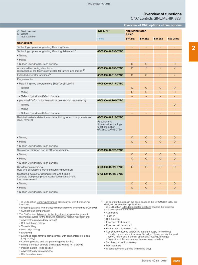
2/29Siemens NC 82 · 2015
Overview of functionsCNC controls SINUMERIK 828
Overview of CNC options – User options
2User options
Technology cycles for grinding Grinding Basic – – – –
Technology cycles for grinding Grinding Advanced:1) 6FC5800-0AS35-0YB0
• Turning – – – –
• Milling – – – –
• G-Tech Cylindrical/G-Tech Surface O O – O
Advanced technology functions (expansion of the technology cycles for turning and milling)2)
6FC5800-0AP58-0YB0 O
Extended operator functions3) 6FC5800-0AP16-0YB0 O O O
Program editor:
• Machining step programming ShopTurn/ShopMill: 6FC5800-0AP17-0YB0
- Turning O O O O
- Milling O O O O
- G-Tech Cylindrical/G-Tech Surface – – – –
• programSYNC – multi-channel step sequence programming: 6FC5800-0AP05-0YB0
- Turning – – – O
- Milling – – – –
- G-Tech Cylindrical/G-Tech Surface – – – –
Residual material detection and machining for contour pockets and stock removal:
6FC5800-0AP13-0YB0
Requirement: Advanced technology functions option6FC5800-0AP58-0YB0
• Turning O O O O
• Milling O O O O
• G-Tech Cylindrical/G-Tech Surface – – – –
Simulation 1 finished part in 3D representation: 6FC5800-0AP25-0YB0
• Turning O O O O
• Milling O O O O
• G-Tech Cylindrical/G-Tech Surface – – – –
Simultaneous recording Real-time simulation of current machining operation
6FC5800-0AP22-0YB0 O O O O
Measuring cycles for drilling/milling and turning Calibrate workpiece probe, workpiece measurement, tool measurement:
6FC5800-0AP28-0YB0
• Turning O O – O
• Milling O O – O
• G-Tech Cylindrical/G-Tech Surface – – – –
Basic version O Option – Not available
Article No. SINUMERIK 828DBASIC
Notes SW 24x SW 26x SW 28x SW 28xA
1) The CNC option Grinding Advanced provides you with the following functions:• Dressing (paraxial form-truing) with stock removal cycles (basic Cycle95)• Cylinder fault compensation
2) The CNC option Advanced technology functions provides you with technology cycles for the following additional machining operations:• Asymmetric grooves (only turning)• Drill and thread milling• Thread milling• Multi-edge milling• Engraving• Extended stock removal along contour with segmentation of blank
(only turning)• Contour grooving and plunge turning (only turning)• Milling of contour pockets and spigots with up to 12 islands• Position pattern - hide position• Asymmetrically turn a shoulder• DIN thread undercut
3) The operator functions in the basic scope of the SINUMERIK 828D are designed for standard applications. The CNC option Extended operator functions enables the following additional operator functions:• Overstoring• Teach-in• DRF function• Extended block search• Extended skip levels > 2• Backup workpiece setup data• Additional measuring version via standard scope (only milling)
- Standard scope workpiece zero: Set edge, align edge, right-angled corner, 1 hole, and 1 circular spigot and rectangular spigot
- Expansion of the measurement masks via combo box• Synchronized actions softkey• MDI load/save• G code converter (turning and milling only)
© Siemens AG 2015
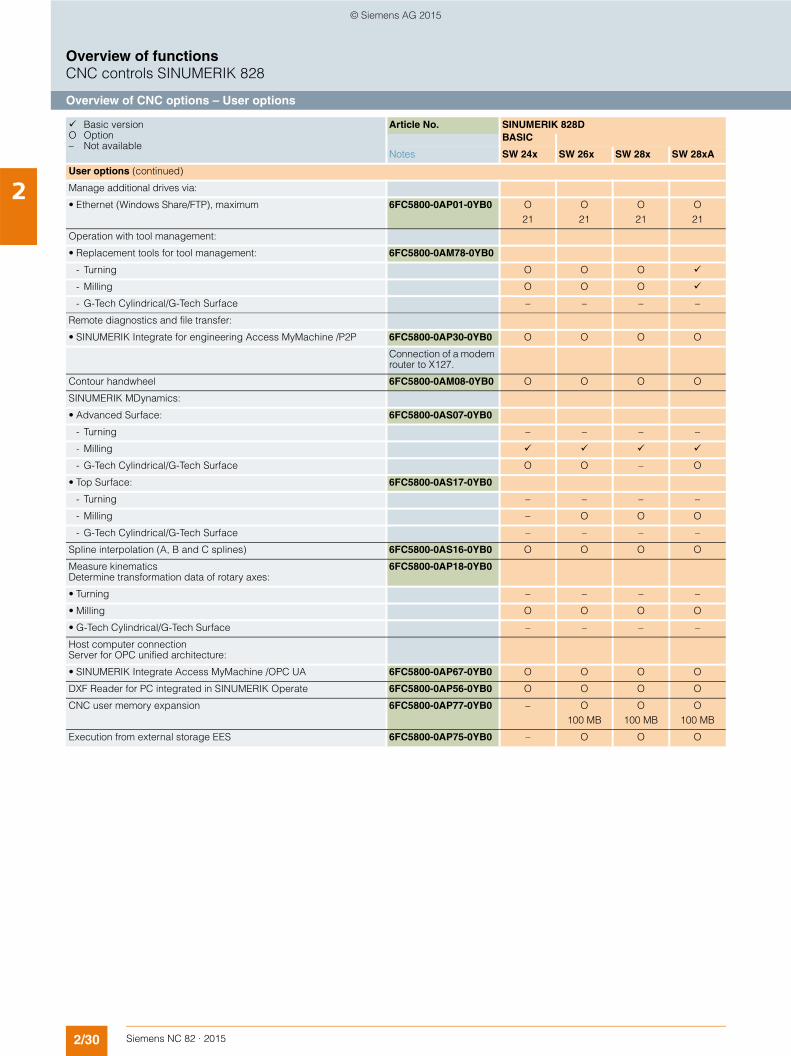
2/30 Siemens NC 82 · 2015
Overview of functionsCNC controls SINUMERIK 828
Overview of CNC options – User options
2User options (continued)
Manage additional drives via:
• Ethernet (Windows Share/FTP), maximum 6FC5800-0AP01-0YB0 O21
O21
O21
O21
Operation with tool management:
• Replacement tools for tool management: 6FC5800-0AM78-0YB0
- Turning O O O
- Milling O O O
- G-Tech Cylindrical/G-Tech Surface – – – –
Remote diagnostics and file transfer:
• SINUMERIK Integrate for engineering Access MyMachine /P2P 6FC5800-0AP30-0YB0 O O O O
Connection of a modem router to X127.
Contour handwheel 6FC5800-0AM08-0YB0 O O O O
SINUMERIK MDynamics:
• Advanced Surface: 6FC5800-0AS07-0YB0
- Turning – – – –
- Milling
- G-Tech Cylindrical/G-Tech Surface O O – O
• Top Surface: 6FC5800-0AS17-0YB0
- Turning – – – –
- Milling – O O O
- G-Tech Cylindrical/G-Tech Surface – – – –
Spline interpolation (A, B and C splines) 6FC5800-0AS16-0YB0 O O O O
Measure kinematics Determine transformation data of rotary axes:
6FC5800-0AP18-0YB0
• Turning – – – –
• Milling O O O O
• G-Tech Cylindrical/G-Tech Surface – – – –
Host computer connection Server for OPC unified architecture:
• SINUMERIK Integrate Access MyMachine /OPC UA 6FC5800-0AP67-0YB0 O O O O
DXF Reader for PC integrated in SINUMERIK Operate 6FC5800-0AP56-0YB0 O O O O
CNC user memory expansion 6FC5800-0AP77-0YB0 – O100 MB
O100 MB
O100 MB
Execution from external storage EES 6FC5800-0AP75-0YB0 – O O O
Basic version O Option – Not available
Article No. SINUMERIK 828DBASIC
Notes SW 24x SW 26x SW 28x SW 28xA
© Siemens AG 2015
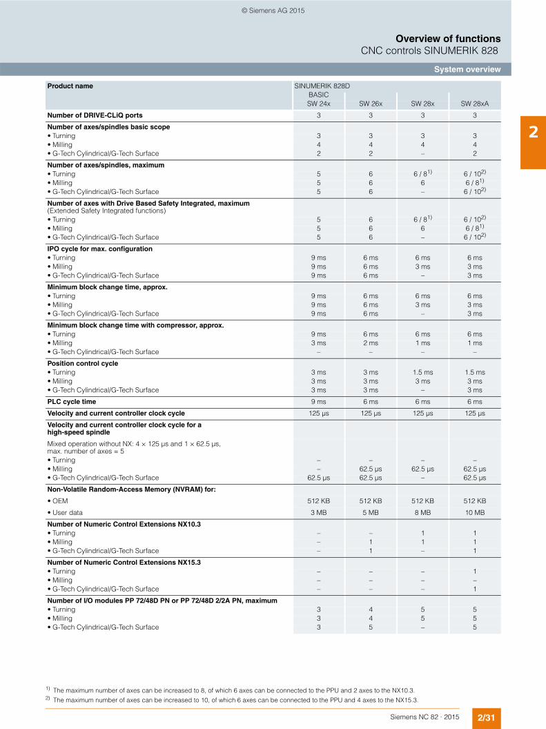
2/31Siemens NC 82 · 2015
Overview of functionsCNC controls SINUMERIK 828
System overview
2
Product name
SINUMERIK 828DBASICSW 24x SW 26x SW 28x SW 28xA
Number of DRIVE-CLiQ ports 3 3 3 3
Number of axes/spindles basic scope• Turning 3 3 3 3• Milling 4 4 4 4• G-Tech Cylindrical/G-Tech Surface 2 2 – 2
Number of axes/spindles, maximum• Turning 5 6 6 / 81) 6 / 102)
• Milling 5 6 6 6 / 81)
• G-Tech Cylindrical/G-Tech Surface 5 6 – 6 / 102)
Number of axes with Drive Based Safety Integrated, maximum(Extended Safety Integrated functions)• Turning 5 6 6 / 81) 6 / 102)
• Milling 5 6 6 6 / 81)
• G-Tech Cylindrical/G-Tech Surface 5 6 – 6 / 102)
IPO cycle for max. configuration• Turning 9 ms 6 ms 6 ms 6 ms• Milling 9 ms 6 ms 3 ms 3 ms• G-Tech Cylindrical/G-Tech Surface 9 ms 6 ms – 3 ms
Minimum block change time, approx. • Turning 9 ms 6 ms 6 ms 6 ms• Milling 9 ms 6 ms 3 ms 3 ms• G-Tech Cylindrical/G-Tech Surface 9 ms 6 ms – 3 ms
Minimum block change time with compressor, approx. • Turning 9 ms 6 ms 6 ms 6 ms• Milling 3 ms 2 ms 1 ms 1 ms• G-Tech Cylindrical/G-Tech Surface – – – –
Position control cycle• Turning 3 ms 3 ms 1.5 ms 1.5 ms• Milling 3 ms 3 ms 3 ms 3 ms• G-Tech Cylindrical/G-Tech Surface 3 ms 3 ms – 3 ms
PLC cycle time 9 ms 6 ms 6 ms 6 ms
Velocity and current controller clock cycle 125 µs 125 µs 125 µs 125 µs
Velocity and current controller clock cycle for a high-speed spindle
Mixed operation without NX: 4 × 125 µs and 1 × 62.5 µs, max. number of axes = 5• Turning – – – –• Milling – 62.5 µs 62.5 µs 62.5 µs• G-Tech Cylindrical/G-Tech Surface 62.5 µs 62.5 µs – 62.5 µs
Non-Volatile Random-Access Memory (NVRAM) for:
• OEM 512 KB 512 KB 512 KB 512 KB
• User data 3 MB 5 MB 8 MB 10 MB
Number of Numeric Control Extensions NX10.3• Turning – – 1 1• Milling – 1 1 1• G-Tech Cylindrical/G-Tech Surface – 1 – 1
Number of Numeric Control Extensions NX15.3• Turning – – – 1• Milling – – – –• G-Tech Cylindrical/G-Tech Surface – – – 1
Number of I/O modules PP 72/48D PN or PP 72/48D 2/2A PN, maximum• Turning 3 4 5 5• Milling 3 4 5 5• G-Tech Cylindrical/G-Tech Surface 3 5 – 5
1) The maximum number of axes can be increased to 8, of which 6 axes can be connected to the PPU and 2 axes to the NX10.3.2) The maximum number of axes can be increased to 10, of which 6 axes can be connected to the PPU and 4 axes to the NX15.3.
© Siemens AG 2015

2/32 Siemens NC 82 · 2015
Overview of functions
Notes
2
© Siemens AG 2015
Siemens NC 82 · 2015
33/2 SINUMERIK 828D BASIC
PPU 241.3/PPU 240.3
3/6 SINUMERIK 828D PPU 261.3/PPU 260.3PPU 281.3/PPU 280.3
3/12 Operator components3/12 SINUMERIK 828 MCP 310 USB3/13 SINUMERIK 828 MCP 483 USB3/14 SINUMERIK MCP Interface PN3/15 Mini handheld unit3/17 Electronic handwheel
3/19 SINUMERIK I/O3/19 SINUMERIK PP 72/48D PN and
PP 72/48D 2/2A PN I/O modules
3/21 Supplementary components3/21 SINAUT MD 720-3 GSM/GPRS modem3/22 SITOP smart power supply
Stabilized power supplies3/23 SENTRON PAC
power monitoring devices
CAD CREATORDimensional drawing and2D/3D CAD generatorwww.siemens.com/cadcreator
Drive Technology Configuratorselection toolGuided product selection through to precise article number www.siemens.com/dt-configurator
CNC controls
© Siemens AG 2015
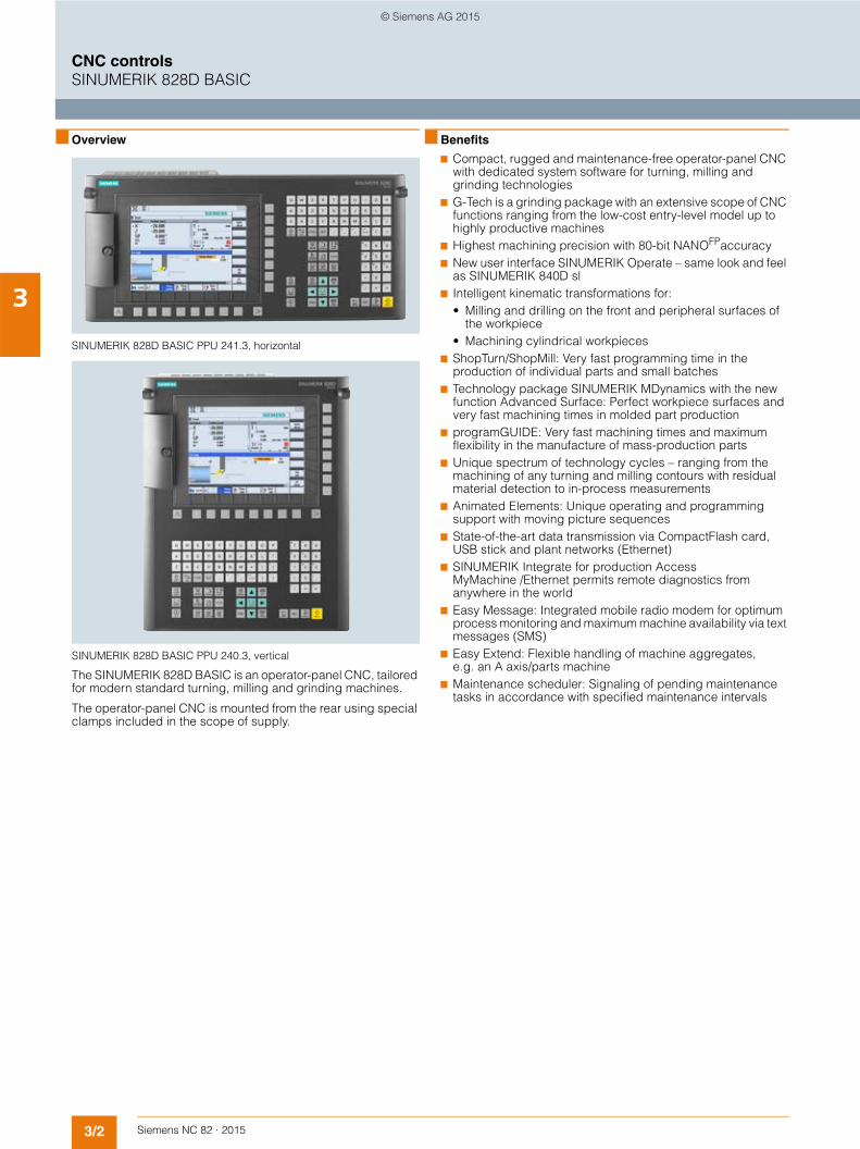
3/2 Siemens NC 82 · 2015
3
CNC controlsSINUMERIK 828D BASIC
■ Overview
SINUMERIK 828D BASIC PPU 241.3, horizontal
SINUMERIK 828D BASIC PPU 240.3, vertical
The SINUMERIK 828D BASIC is an operator-panel CNC, tailored for modern standard turning, milling and grinding machines.
The operator-panel CNC is mounted from the rear using special clamps included in the scope of supply.
■ Benefits
7 Compact, rugged and maintenance-free operator-panel CNC with dedicated system software for turning, milling and grinding technologies
7 G-Tech is a grinding package with an extensive scope of CNC functions ranging from the low-cost entry-level model up to highly productive machines
7 Highest machining precision with 80-bit NANOFPaccuracy7 New user interface SINUMERIK Operate – same look and feel
as SINUMERIK 840D sl7 Intelligent kinematic transformations for:
• Milling and drilling on the front and peripheral surfaces of the workpiece
• Machining cylindrical workpieces7 ShopTurn/ShopMill: Very fast programming time in the
production of individual parts and small batches7 Technology package SINUMERIK MDynamics with the new
function Advanced Surface: Perfect workpiece surfaces and very fast machining times in molded part production
7 programGUIDE: Very fast machining times and maximum flexibility in the manufacture of mass-production parts
7 Unique spectrum of technology cycles – ranging from the machining of any turning and milling contours with residual material detection to in-process measurements
7 Animated Elements: Unique operating and programming support with moving picture sequences
7 State-of-the-art data transmission via CompactFlash card, USB stick and plant networks (Ethernet)
7 SINUMERIK Integrate for production Access MyMachine /Ethernet permits remote diagnostics from anywhere in the world
7 Easy Message: Integrated mobile radio modem for optimum process monitoring and maximum machine availability via text messages (SMS)
7 Easy Extend: Flexible handling of machine aggregates, e.g. an A axis/parts machine
7 Maintenance scheduler: Signaling of pending maintenance tasks in accordance with specified maintenance intervals
© Siemens AG 2015

3/3Siemens NC 82 · 2015
3
CNC controlsSINUMERIK 828D BASIC
■ Function
• Operator panel variants for horizontal or vertical operator panel housings
• Integrated QWERTY full CNC keyboard with short-stroke keys• CompactFlash card, USB and Ethernet interfaces on the
operator panel front• Additional Ethernet interface on rear of CNC for connection to
factory network• Integrated PLC based on the SIMATIC S7-200 command set
with ladder logic programming• I/O interface based on PROFINET for the connection of PLC
I/O devices and a machine control panel• Connection for a GSM/GPRS modem: Easy Message (option)• CNC options subject to license• Up to 5 axes/spindles for turning and milling applications • 1 analog spindle
• 1 machining channel/mode group• Integrated tool management with tool life monitoring• Management of replacement tools (option)• Graphical machining step programming ShopTurn/ShopMill
(option)• Configurable user screens with
SINUMERIK Integrate for engineering Run MyScreens (Easy Screen)
• SINUMERIK Integrate for engineering Run MyRobot /EasyConnect for simple interfacing of robots and handling systems
• Integrated data archiving procedure for simple data updates• Faults will be remedied for a period of 24 months following
2nd commissioning on all system components in accordance with the on-site service contract performance description
■ Integration
The following components can be connected to the SINUMERIK 828D BASIC:• 2 electronic handwheels1)
• Mini handheld unit with handwheel• 3 SINUMERIK PP 72/48D PN or
PP 72/48D 2/2A PN I/O modules• SINUMERIK MCP 310 USB or MCP 483 USB
machine control panel
• SINUMERIK MCP Interface PN• GSM/GPRS modem• SENTRON PAC Power Monitoring Devices• SINAMICS S120 Combi drive system via DRIVE-CLiQ
SINUMERIK 828D BASIC configuration with SINAMICS S120 Combi
DRIVE-CLiQ
SINAMICS S120Motor Modulebooksize compactformat
1FK7feed motor
1FK7feed motor
1FK7feed motor
1FK7 feed motor 1PH8 auxiliary spindle
1PH8spindle motor
3 AC380 ... 480 V
SINAMICS S120Combi
Linereactor
Line filter (optional)
Spindle encoder TTL
Up to 5 linear scales
DMC20/DME20
G_N
C01
_EN
_004
33a
Analog spindle
SINUMERIK 828DBASIC
1) Third handwheel possible via MCP Interface PN. Application: Manual machine.
© Siemens AG 2015
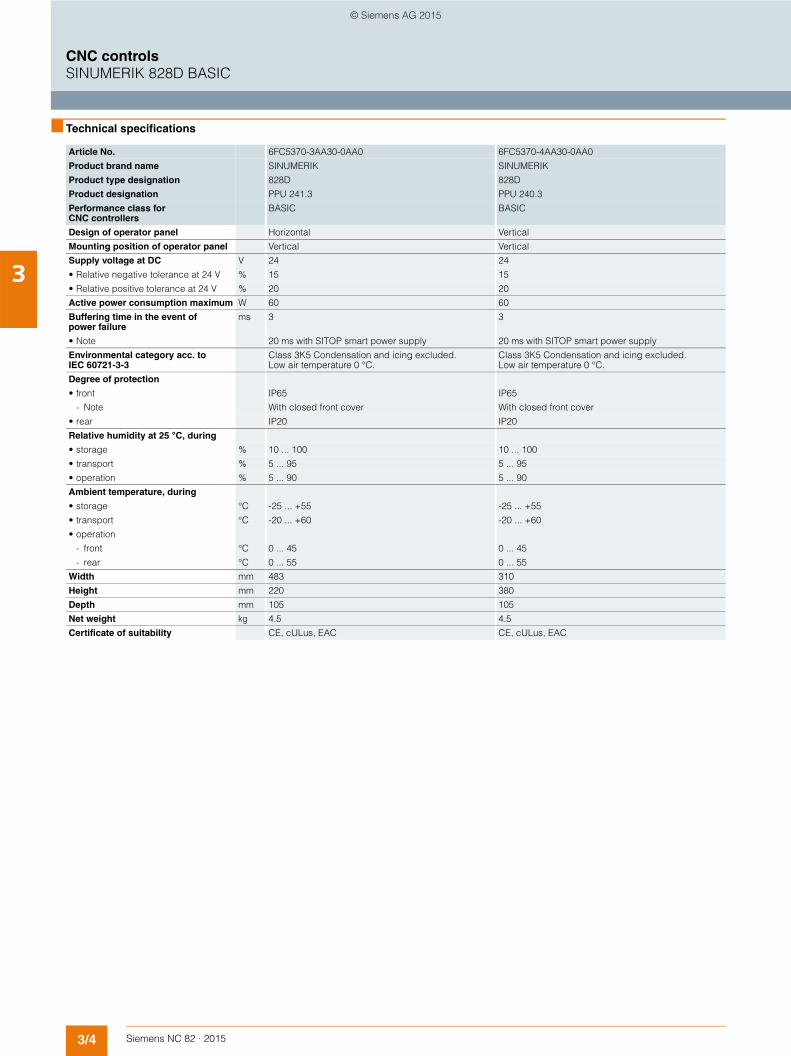
3/4 Siemens NC 82 · 2015
3
CNC controlsSINUMERIK 828D BASIC
■ Technical specifications
Article No. 6FC5370-3AA30-0AA0 6FC5370-4AA30-0AA0
Product brand name SINUMERIK SINUMERIK
Product type designation 828D 828D
Product designation PPU 241.3 PPU 240.3
Performance class for CNC controllers
BASIC BASIC
Design of operator panel Horizontal Vertical
Mounting position of operator panel Vertical Vertical
Supply voltage at DC V 24 24
• Relative negative tolerance at 24 V % 15 15
• Relative positive tolerance at 24 V % 20 20
Active power consumption maximum W 60 60
Buffering time in the event of power failure
ms 3 3
• Note 20 ms with SITOP smart power supply 20 ms with SITOP smart power supply
Environmental category acc. to IEC 60721-3-3
Class 3K5 Condensation and icing excluded. Low air temperature 0 °C.
Class 3K5 Condensation and icing excluded. Low air temperature 0 °C.
Degree of protection
• front IP65 IP65
- Note With closed front cover With closed front cover
• rear IP20 IP20
Relative humidity at 25 °C, during
• storage % 10 ... 100 10 ... 100
• transport % 5 ... 95 5 ... 95
• operation % 5 ... 90 5 ... 90
Ambient temperature, during
• storage °C -25 ... +55 -25 ... +55
• transport °C -20 ... +60 -20 ... +60
• operation
- front °C 0 ... 45 0 ... 45
- rear °C 0 ... 55 0 ... 55
Width mm 483 310
Height mm 220 380
Depth mm 105 105
Net weight kg 4.5 4.5
Certificate of suitability CE, cULus, EAC CE, cULus, EAC
© Siemens AG 2015
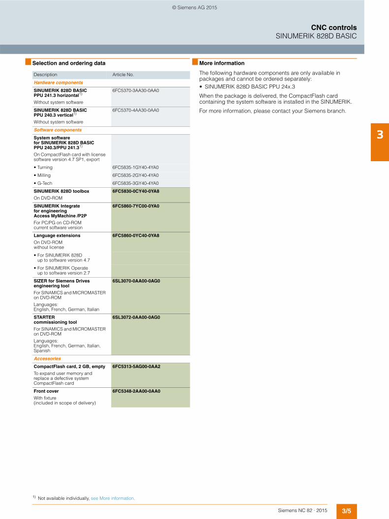
3/5Siemens NC 82 · 2015
3
CNC controlsSINUMERIK 828D BASIC
■ Selection and ordering data ■ More information
The following hardware components are only available in packages and cannot be ordered separately:• SINUMERIK 828D BASIC PPU 24x.3
When the package is delivered, the CompactFlash card containing the system software is installed in the SINUMERIK.
For more information, please contact your Siemens branch.
Description Article No.
Hardware components
SINUMERIK 828D BASIC PPU 241.3 horizontal1)
Without system software
6FC5370-3AA30-0AA0
SINUMERIK 828D BASIC PPU 240.3 vertical1)
Without system software
6FC5370-4AA30-0AA0
Software components
System software for SINUMERIK 828D BASIC PPU 240.3/PPU 241.31)
On CompactFlash card with license software version 4.7 SP1, export
• Turning 6FC5835-1GY40-4YA0
• Milling 6FC5835-2GY40-4YA0
• G-Tech 6FC5835-3GY40-4YA0
SINUMERIK 828D toolbox
On DVD-ROM
6FC5830-0CY40-0YA8
SINUMERIK Integrate for engineering Access MyMachine /P2P
For PC/PG on CD-ROMcurrent software version
6FC5860-7YC00-0YA0
Language extensions
On DVD-ROM without license
6FC5860-0YC40-0YA8
• For SINUMERIK 828D up to software version 4.7
• For SINUMERIK Operate up to software version 2.7
SIZER for Siemens Drives engineering tool
For SINAMICS and MICROMASTER on DVD-ROM
Languages:English, French, German, Italian
6SL3070-0AA00-0AG0
STARTER commissioning tool
For SINAMICS and MICROMASTER on DVD-ROM
Languages:English, French, German, Italian, Spanish
6SL3072-0AA00-0AG0
Accessories
CompactFlash card, 2 GB, empty
To expand user memory and replace a defective system CompactFlash card
6FC5313-5AG00-0AA2
Front cover
With fixture (included in scope of delivery)
6FC5348-2AA00-0AA0
1) Not available individually, see More information.
© Siemens AG 2015

3/6 Siemens NC 82 · 2015
3
CNC controlsSINUMERIK 828D
■ Overview
SINUMERIK 828D PPU 261.3/PPU 281.3, horizontal
SINUMERIK 828D PPU 260.3/PPU 280.3, vertical
The SINUMERIK 828D is an operator-panel CNC which combines all the components of a CNC in one unit:• CNC, PLC, HMI• Full CNC keyboard• Closed-loop control for 6 drives
The motors can easily be connected to the digital drive system via DRIVE-CLiQ. In combination with the modular structure of the SINAMICS S120 drive system, this design is conceived to ensure very simple and rugged installation with minimum wiring overhead.
The performance range of the CNC has been precisely selected to meet the requirements of standard turning, milling and grinding machines – from one-off production runs to industrial scale manufacture. Thanks to the technology-specific variants for turning, milling and grinding, the system parameters are optimized for the machine, making the commissioning process much quicker and easier.
The operator-panel CNC is mounted from the rear using special clamps included in the scope of supply.
■ Benefits
Benefits for the machine operator7 High-quality, rugged, magnesium die-cast operator panels7 Extremely user-friendly operation through integrated QWERTY
keyboard with short-stroke keys7 Easy data exchange thanks to USB and Ethernet interfaces on
the operator panel front7 Simple operation using ShopTurn and ShopMill software7 Advanced Surface: Innovative, high-performance CNC
functions provide top quality of workpiece surface with minimum machining times
7 Unique spectrum of technology cycles – ranging from the machining of any turning and milling contours with residual material detection to in-process measurements and balance cutting
7 Animated Elements: Optimum operator guidance thanks to CNC input screens with animated elements
7 Easy input via CNC direct keys on the CNC keyboard7 SINUMERIK Integrate for production Access
MyMachine /Ethernet permits remote diagnostics from anywhere in the world
7 Easy Message: Integrated mobile radio modem for optimum process monitoring and maximum machine availability via text messages (SMS)
7 Easy Extend: Flexible handling of machine aggregates, e.g. an A axis/parts machine
7 Maintenance scheduler: Signaling of pending maintenance tasks in accordance with specified maintenance intervals
Benefits for the machine manufacturer7 High system quality through reduction in hardware interfaces7 Drive-based Safety Integrated for compliance with the
machinery directive7 Less complex system thanks to technology-specific system
software7 Faster, easier commissioning thanks to preset system
parameters7 Automatic system configuration by means of single PLC I/Os7 Service Planner: Integrated planner for machine maintenance
intervals7 Easy Archive: Integrated archiving procedure for optimum
handling of commissioning updates7 Easy Extend: Integrated wizard for optional machine units7 Simple PLC programming with symbols and comments
on the CNC7 No outlay required by dealers and machine manufacturers
thanks to free PLC programming tool7 Faults will be remedied for a period of 24 months following
2nd commissioning on all system components in accordance with the on-site service contract performance description
© Siemens AG 2015
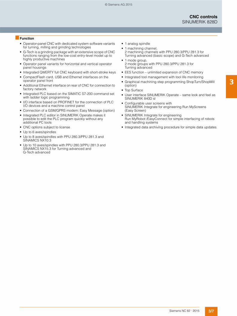
3/7Siemens NC 82 · 2015
3
CNC controlsSINUMERIK 828D
■ Function
• Operator-panel CNC with dedicated system software variants for turning, milling and grinding technologies
• G-Tech is a grinding package with an extensive scope of CNC functions ranging from the low-cost entry-level model up to highly productive machines
• Operator panel variants for horizontal and vertical operator panel housings
• Integrated QWERTY full CNC keyboard with short-stroke keys• CompactFlash card, USB and Ethernet interfaces on the
operator panel front• Additional Ethernet interface on rear of CNC for connection to
factory network• Integrated PLC based on the SIMATIC S7-200 command set
with ladder logic programming• I/O interface based on PROFINET for the connection of PLC
I/O devices and a machine control panel• Connection of a GSM/GPRS modem: Easy Message (option)• Integrated PLC editor in SINUMERIK Operate makes it
possible to edit the PLC program quickly without any additional PC tools
• CNC options subject to license• Up to 6 axes/spindles• Up to 8 axes/spindles with PPU 280.3/PPU 281.3 and
SINAMICS NX10.3• Up to 10 axes/spindles with PPU 280.3/PPU 281.3 and
SINAMICS NX15.3 for Turning advanced and G-Tech advanced
• 1 analog spindle• 1 machining channel,
2 machining channels with PPU 280.3/PPU 281.3 for Turning advanced (basic scope) and G-Tech advanced
• 1 mode group, 2 mode groups with PPU 280.3/PPU 281.3 for Turning advanced
• EES function – unlimited expansion of CNC memory• Integrated tool management with tool life monitoring• Graphical machining step programming ShopTurn/ShopMill
(option)• Top Surface• User interface SINUMERIK Operate – same look and feel as
SINUMERIK 840D sl• Configurable user screens with
SINUMERIK Integrate for engineering Run MyScreens (Easy Screen)
• SINUMERIK Integrate for engineering Run MyRobot /EasyConnect for simple interfacing of robots and handling systems
• Integrated data archiving procedure for simple data updates
© Siemens AG 2015

3/8 Siemens NC 82 · 2015
3
CNC controlsSINUMERIK 828D
■ Integration
The following components can be connected to the SINUMERIK 828D:• 2 electronic handwheels1)
• Mini handheld unit with handwheel• 3 SINUMERIK PP 72/48D PN or
PP 72/48D 2/2A PN I/O modules• SINUMERIK MCP 310 USB or MCP 483 USB
machine control panel• SINUMERIK MCP Interface PN• GSM/GPRS modem• SENTRON PAC Power Monitoring Devices• SINAMICS S120 drive system via DRIVE-CLiQ• SINAMICS Numeric Control Extension NX10.3
(not with PPU 260.3/PPU 261.3 for Turning and G-Tech)
• SINAMICS Numeric Control Extension NX15.3 (only with PPU 280.3/PPU 281.3 for Turning advanced and G-Tech advanced)
• Expansion of the SINUMERIK 828D system by additional auxiliary axes for loading axes, parts catchers or other auxiliary modules
SINUMERIK 828D configuration with SINAMICS S120
G_N
C01
_EN
_004
42c
(Service Interface TCP/IP)
Mini handheld unit
DMC20 encodersystem connection
PN/PN coupler
Handwheel
SINAMICS S120Motor Module
SINAMICS S120
SINAMICSNX10.3
GSM/GPRS modem
Modem router
Ethernet
Ethernet (Factory network TCP/IP)
Analog spindle
1FK7feed motor
1PH8spindle motor
1PH8spindle motor
PC/PG
RS232C
SINUMERIK 828D
MCP 483 USB
PP 72/48D PN/PP 72/48D 2/2A PN
PROFINET
DRIVE-CLiQ
PC
1) Third handwheel possible via MCP Interface PN. Application: Manual machine.
© Siemens AG 2015
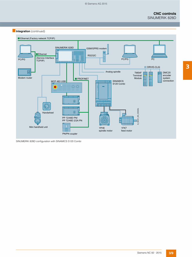
3/9Siemens NC 82 · 2015
3
■ Integration (continued)
CNC controlsSINUMERIK 828D
SINUMERIK 828D configuration with SINAMICS S120 Combi
PN/PN coupler
G_N
C01
_EN
_005
45b
Mini handheld unit
DMC20 encodersystem connection
Handwheel
SINUMERIK 828D GSM/GPRS modem
Modem router
(Service Interface TCP/IP)
Ethernet
Ethernet (Factory network TCP/IP)
TM54FTerminal
Module
Analog spindle
1FK7feed motor
1PH8spindle motor
SINAMICS S120 Combi
PCPC/PG
DRIVE-CLiQ
PROFINET
PP 72/48D PN/PP 72/48D 2/2A PN
MCP 483 USB
RS232C
PC/PG
© Siemens AG 2015
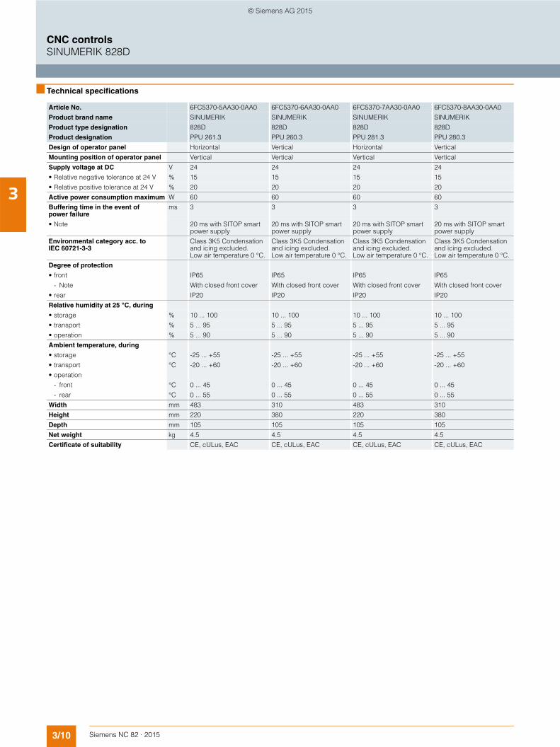
3/10 Siemens NC 82 · 2015
3
CNC controlsSINUMERIK 828D
■ Technical specifications
Article No. 6FC5370-5AA30-0AA0 6FC5370-6AA30-0AA0 6FC5370-7AA30-0AA0 6FC5370-8AA30-0AA0
Product brand name SINUMERIK SINUMERIK SINUMERIK SINUMERIK
Product type designation 828D 828D 828D 828D
Product designation PPU 261.3 PPU 260.3 PPU 281.3 PPU 280.3
Design of operator panel Horizontal Vertical Horizontal Vertical
Mounting position of operator panel Vertical Vertical Vertical Vertical
Supply voltage at DC V 24 24 24 24
• Relative negative tolerance at 24 V % 15 15 15 15
• Relative positive tolerance at 24 V % 20 20 20 20
Active power consumption maximum W 60 60 60 60
Buffering time in the event of power failure
ms 3 3 3 3
• Note 20 ms with SITOP smart power supply
20 ms with SITOP smart power supply
20 ms with SITOP smart power supply
20 ms with SITOP smart power supply
Environmental category acc. to IEC 60721-3-3
Class 3K5 Condensation and icing excluded. Low air temperature 0 °C.
Class 3K5 Condensation and icing excluded. Low air temperature 0 °C.
Class 3K5 Condensation and icing excluded. Low air temperature 0 °C.
Class 3K5 Condensation and icing excluded. Low air temperature 0 °C.
Degree of protection
• front IP65 IP65 IP65 IP65
- Note With closed front cover With closed front cover With closed front cover With closed front cover
• rear IP20 IP20 IP20 IP20
Relative humidity at 25 °C, during
• storage % 10 ... 100 10 ... 100 10 ... 100 10 ... 100
• transport % 5 ... 95 5 ... 95 5 ... 95 5 ... 95
• operation % 5 ... 90 5 ... 90 5 ... 90 5 ... 90
Ambient temperature, during
• storage °C -25 ... +55 -25 ... +55 -25 ... +55 -25 ... +55
• transport °C -20 ... +60 -20 ... +60 -20 ... +60 -20 ... +60
• operation
- front °C 0 ... 45 0 ... 45 0 ... 45 0 ... 45
- rear °C 0 ... 55 0 ... 55 0 ... 55 0 ... 55
Width mm 483 310 483 310
Height mm 220 380 220 380
Depth mm 105 105 105 105
Net weight kg 4.5 4.5 4.5 4.5
Certificate of suitability CE, cULus, EAC CE, cULus, EAC CE, cULus, EAC CE, cULus, EAC
© Siemens AG 2015
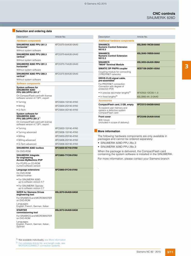
3/11Siemens NC 82 · 2015
3
CNC controlsSINUMERIK 828D
■ Selection and ordering data
■ More information
The following hardware components are only available in packages and cannot be ordered separately:• SINUMERIK 828D PPU 26x.3• SINUMERIK 828D PPU 28x.3
When the package is delivered, the CompactFlash card containing the system software is installed in the SINUMERIK.
For more information, please contact your Siemens branch
.
Description Article No.
Hardware components
SINUMERIK 828D PPU 261.3 horizontal1)
Without system software
6FC5370-5AA30-0AA0
SINUMERIK 828D PPU 260.3 vertical1)
Without system software
6FC5370-6AA30-0AA0
SINUMERIK 828D PPU 281.3 horizontal1)
Without system software
6FC5370-7AA30-0AA0
SINUMERIK 828D PPU 280.3 vertical1)
Without system software
6FC5370-8AA30-0AA0
Software components
System software for SINUMERIK 828D PPU 260.3/PPU 261.31)
On CompactFlash card with license software version 4.7 SP1, export
• Turning 6FC5834-1GY40-4YA0
• Milling 6FC5834-2GY40-4YA0
• G-Tech 6FC5834-3GY40-4YA0
System software forSINUMERIK 828D PPU 280.3/PPU 281.31)
On CompactFlash card with license software version 4.7 SP1, export
• Turning 6FC5833-1GY40-4YA0
• Turning advanced 6FC5836-1GY40-4YA0
• Milling 6FC5833-2GY40-4YA0
• Milling advanced 6FC5836-2GY40-4YA0
• G-Tech advanced 6FC5836-3GY40-4YA0
SINUMERIK 828D toolbox
On DVD-ROM
6FC5830-0CY40-0YA8
SINUMERIK Integrate for engineering Access MyMachine /P2P
For PC/PG on CD-ROMcurrent software version
6FC5860-7YC00-0YA0
Language extensions
On DVD-ROM without license
6FC5860-0YC40-0YA8
• For SINUMERIK 828D up to software version 4.7
• For SINUMERIK Operateup to software version 2.7
SIZER for Siemens Drives engineering tool
For SINAMICS and MICROMASTER on DVD-ROM
Languages:English, French, German, Italian
6SL3070-0AA00-0AG0
STARTER commissioning tool
For SINAMICS and MICROMASTER on DVD-ROM
Languages:English, French, German, Italian, Spanish
6SL3072-0AA00-0AG0
Description Article No.
Additional hardware components
SINAMICS Numeric Control Extension NX10.3
6SL3040-1NC00-0AA0
SINAMICS Numeric Control Extension NX15.3
6SL3040-1NB00-0AA0
SINAMICS TM54F Terminal Module
6SL3055-0AA00-3BA0
SIMATIC DP PN/PN coupler
Coupling module for connecting 2 PROFINET networks
6ES7158-3AD01-0XA0
DRIVE-CLiQ signal cable, pre-assembled
For PROFINET connection Connector with degree of protection IP20
• In precise decimeter lengths2) 6FX2002-1DC00-1..0
• In fixed lengths2) 6SL3060-4A..0-0AA0
Accessories
CompactFlash card, 2 GB, empty
To expand user memory and replace a defective system CompactFlash card
6FC5313-5AG00-0AA2
Front cover
With fixture (included in scope of delivery)
6FC5348-2AA00-0AA0
1) Not available individually, see More information.2) For complete Article No. and length code, see
MOTION-CONNECT connection systems.
© Siemens AG 2015
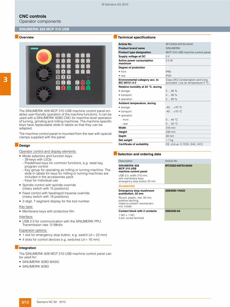
3/12 Siemens NC 82 · 2015
3
CNC controlsOperator components
SINUMERIK 828 MCP 310 USB
■ Overview
The SINUMERIK 828 MCP 310 USB machine control panel en-ables user-friendly operation of the machine functions. It can be used with a SINUMERIK 828D CNC for machine-level operation of turning, grinding and milling machines. The machine-specific keys have replaceable slide-in labels so that they can be adapted.
The machine control panel is mounted from the rear with special clamps supplied with the panel.
■ Design
Operator control and display elements:• Mode selectors and function keys:
- 39 keys with LEDs- Predefined keys for common functions, e.g. reset key,
program control- Key group for operating as milling or turning machine. The
slide-in labels for keys for milling or turning machines are included in the accessories pack.
- Keys for individual use• Spindle control with spindle override
(rotary switch with 15 positions)• Feed control with feed/rapid traverse override
(rotary switch with 18 positions)• 2-digit, 7-segment display for the tool number
Key type:• Membrane keys with protective film
Interface:• USB 2.0 for communication with the SINUMERIK PPU:
Transmission rate 12 Mbit/s
Expansion options:• 1 slot for emergency stop button, e.g. switch (d = 22 mm)• 4 slots for control devices e.g. switches (d = 16 mm)
■ Integration
The SINUMERIK 828 MCP 310 USB machine control panel can be used for:• SINUMERIK 828D BASIC• SINUMERIK 828D
■ Technical specifications
■ Selection and ordering data
Article No. 6FC5303-0AF33-0AA0
Product brand name SINUMERIK
Product type designation MCP 310 USB machine control panel
Supply voltage at DC 5 V
Active power consumption maximum
2.5 W
Degree of protection
• front IP65
• rear IP20
Environmental category acc. to IEC 60721-3-3
Class 3K5 Condensation and icing excluded. Low air temperature 0 °C.
Relative humidity at 25 °C, during
• storage 5 ... 95 %
• transport 5 ... 95 %
• operation 5 ... 85 %
Ambient temperature, during
• storage -40 ... +70 °C
• transport -40 ... +70 °C
• operation
- front 0 ... 45 °C
- rear 0 ... 55 °C
Width 310 mm
Height 230 mm
Depth 49 mm
Net weight 1.1 kg
Certificate of suitability CE, cULus, C-TICK, EAC, KCC
Description Article No.
SINUMERIK 828 MCP 310 USB machine control panel
USB 2.0, width 310 mm, with membrane keys emergency stop button 22 mm
6FC5303-0AF33-0AA0
Accessories
Emergency stop mushroom pushbutton, 22 mm
Round, plastic, red, 40 mm, positive latching, rotate-to-unlatch mechanism, incl. holder
3SB3000-1HA20
Contact block with 2 contacts
1 NO + 1 NC, 2-pin, screw terminal
3SB3400-0A
© Siemens AG 2015

3/13Siemens NC 82 · 2015
3
CNC controlsOperator components
SINUMERIK 828 MCP 483 USB
■ Overview
The SINUMERIK 828 MCP 483 USB machine control panel enables user-friendly operation of the machine functions. It can be used with a SINUMERIK 828D CNC for machine-level operation of turning, grinding and milling machines. The machine-specific keys have replaceable slide-in labels so that they can be adapted.
The machine control panel is mounted from the rear with special clamps supplied with the panel.
■ Design
Operator control and display elements:• Mode selectors and function keys:
- 40 keys with LEDs- Predefined keys for common functions, e.g. reset key,
program control- Key group for operating as milling or turning machine.
The slide-in labels for keys for milling or turning machines are included in the accessories pack.
- Keys for individual use• Spindle control with spindle override
(rotary switch with 15 positions)• Feed control with feed/rapid traverse override
(rotary switch with 18 positions)• 2-digit, 7-segment display for the tool number
Key type:• Membrane keys with protective film
Interface:• USB 2.0 for communication with the SINUMERIK PPU:
Transmission rate 12 Mbit/s
Expansion options:• 1 slot for emergency stop button, e.g. switch (d = 22 mm)• 2 slots for control devices e.g. switches (d = 16 mm)
■ Integration
The SINUMERIK 828 MCP 483 USB machine control panel can be used for:• SINUMERIK 828D BASIC• SINUMERIK 828D
■ Technical specifications
■ Selection and ordering data
Article No. 6FC5303-0AF32-0AA0
Product brand name SINUMERIK
Product type designation MCP 483 USB machine control panel
Supply voltage at DC 5 V
Active power consumption maximum
2.5 W
Degree of protection
• front IP65
• rear IP20
Environmental category acc. to IEC 60721-3-3
Class 3K5 Condensation and icing excluded. Low air temperature 0 °C.
Relative humidity at 25 °C, during
• storage 5 ... 95 %
• transport 5 ... 95 %
• operation 5 ... 85 %
Ambient temperature, during
• storage -40 ... +70 °C
• transport -40 ... +70 °C
• operation
- front 0 ... 45 °C
- rear 0 ... 55 °C
Width 483 mm
Height 155 mm
Depth 49 mm
Net weight 1.22 kg
Certificate of suitability CE, cULus, C-TICK, EAC, KCC
Description Article No.
SINUMERIK 828 MCP 483 USB machine control panel
USB 2.0, width 19”, with membrane keys emergency stop button 22 mm
6FC5303-0AF32-0AA0
Accessories
Emergency stop mushroom pushbutton, 22 mm
Round, plastic, red, 40 mm, positive latching, rotate-to-unlatch mechanism, incl. holder
3SB3000-1HA20
Contact block with 2 contacts
1 NO + 1 NC, 2-pin, screw terminal
3SB3400-0A
© Siemens AG 2015

3/14 Siemens NC 82 · 2015
3
CNC controlsOperator components
SINUMERIK MCP Interface PN
■ Overview
SINUMERIK MCP Interface PN
The SINUMERIK MCP Interface PN enables customer-specific machine control panels to be connected via PROFINET.
On the SINUMERIK MCP Interface PN, digital inputs, outputs, connections for override rotary switches and handwheels are provided as well as two Industrial Ethernet interfaces for communication.
■ Design
You can connect the following operator controls to the SINUMERIK MCP Interface PN:• 80 single keys• 64 LEDs• 1 handwheel• 2 override switches
The following inputs/outputs are also available:• 9 digital inputs (5 V)• 6 digital inputs (24 V)• 15 digital outputs (24 V/each 0.15 A)
■ Integration
The SINUMERIK MCP Interface PN can be used for:• SINUMERIK 828D BASIC• SINUMERIK 828D
■ Technical specifications
■ Selection and ordering data
Article No. 6FC5303-0AF03-0AA0
Product brand name SINUMERIK
Product type designation MCP Interface PN
Supply voltage at DC 24 V
Active power consumption maximum
62.4 W of all connectable operator controls 2.4 W intrinsic consumption
Degree of protection IP00
Environmental category acc. to IEC 60721-3-3
Condensation and icing excluded. Low air temperature 0 °C.
Relative humidity at 25 °C, during
• storage 5 ... 95 %
• transport 5 ... 95 %
• operation 5 ... 95 %
Ambient temperature, during
• storage -25 ... +55 °C
• transport -40 ... +70 °C
• operation
- front 0 ... 45 °C
- rear 0 ... 55 °C
Width 242 mm
Height 152 mm
Depth 36 mm
Net weight 0.557 kg
Certificate of suitability CE, cULus, EAC
Description Article No.
SINUMERIK MCP Interface PN
For connecting to customized machine control panels over PROFINET
6FC5303-0AF03-0AA0
Accessories
Feed/rapid traverse overrideelectronic rotary switch
1 × 23G, T=32, cap, button, pointer, andrapid traverse and feed dials1)
6FC5247-0AF13-1AA0
Spindle/rapid traverse overrideelectronic rotary switch
1 × 16G, T=24, cap, button, pointer, andrapid traverse and spindle dials2)
6FC5247-0AF12-1AA00
Cable set (60 units)
For additional control devices
Length: 500 mm
6FC5247-0AA35-0AA0
1) 23G: Latching at position 23; T=32: 32 positions for 360°2) 16G: Latching at position 16; T=24: 24 positions for 360°
© Siemens AG 2015
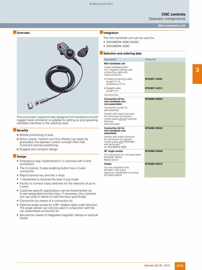
3/15Siemens NC 82 · 2015
3
CNC controlsOperator components
Mini handheld unit
■ Overview
The convenient, ergonomically designed mini handheld unit with rugged metal connector is suitable for setting up and operating standard machines in the Jobshop area.
■ Benefits
7 Mobile positioning of axes7 Since coarse, medium and fine infeeds can easily be
graduated, the operator control concept offers fast, increment-precise positioning
7 Rugged and compact design
■ Design
• Emergency stop implemented in 2 channels with 4-wire connection
• The 2-channel, 3-step enabling button has a 3-wire connection.
• Rapid traverse key and two ± keys• 1 handwheel to traverse the axes in jog mode• Facility to connect rotary switches for the selection of up to
5 axes• Customer-specific applications can be implemented via
3 user-assignable function keys. If necessary, the customer can use slide-in labels to mark the keys specifically.
• Connection by means of a connection kit.• Optional angle socket for a 90° rotated cable outlet direction.
The angle socket can only be used in conjunction with the non-assembled connection kit.
• Secured by means of integrated magnetic clamps or optional holder
■ Integration
The mini handheld unit can be used for:• SINUMERIK 828D BASIC• SINUMERIK 828D
■ Selection and ordering data
Description Article No.
Mini handheld unit
3-step enabling button incl. magnetic clamps and connecting cable with metal connector
• Coiled connecting cableLength 2.1 m, stretches to 3.5 m
6FX2007-1AD03
• Straight cableLength 5 m
6FX2007-1AD13
Accessories
Connection kit for mini handheld unit, non-assembled
Connection socket for self-assembly
Version with metal connector for connection to machine control panel without Industrial Ethernet, with terminator
6FX2006-1BG03
Connection kit for mini handheld unit, assembled
Version with metal connector for connection to machine control panel with PROFINET, with terminator for SINUMERIK 828D
6FX2006-1BG20
90° angle socket
For connection kit, non-assembled 6FX2006-1BG03Metal version
6FX2006-1BG56
Holder
For mini handheld units 6FX2007-1AD.3 andelectronic handwheel in housing 6FC9320-5DE02
6FX2006-1BG70
© Siemens AG 2015
3/16 Siemens NC 82 · 2015
3
CNC controlsOperator components
Mini handheld unit
■ Technical specifications
Article No. 6FX2007-1AD03 6FX2007-1AD13
Product brand name SINUMERIK SINUMERIK
Product type designation Mini handheld unit Mini handheld unit
Product property With coiled cable With straight cable
Supply voltage at DC V 24 24
• Note For emergency stop button, enabling buttons and switching signals
For emergency stop button, enabling buttons and switching signals
• for handwheel V 5 5
Design of the interface RS422 RS422
Number of pulses per revolution maximum
100 100
Transmission link to the PPU maximum
m 25 25
Transmission link to the NCU/PCU maximum
m 25 25
• Note When using the handwheel When using the handwheel
Protection class without shaft input IP65 IP65
Environmental category acc. to IEC 60721-3-3
Condensation and icing excluded. Low air temperature 0 °C.
Condensation and icing excluded. Low air temperature 0 °C.
Relative humidity at 25 °C, during
• storage % 5 ... 95 5 ... 95
• transport % 5 ... 95 5 ... 95
• operation % 5 ... 95 5 ... 95
Ambient temperature, during
• storage °C -20 ... +60 -20 ... +60
• transport °C -20 ... +60 -20 ... +60
• operation °C 0 ... 55 0 ... 55
Width mm 90 90
Height mm 67 67
Depth mm 180 180
• Note With emergency stop button With emergency stop button
Net weight kg 0.5 0.5
• Note Without connecting cable Without connecting cable
Certificate of suitability CE CE
© Siemens AG 2015
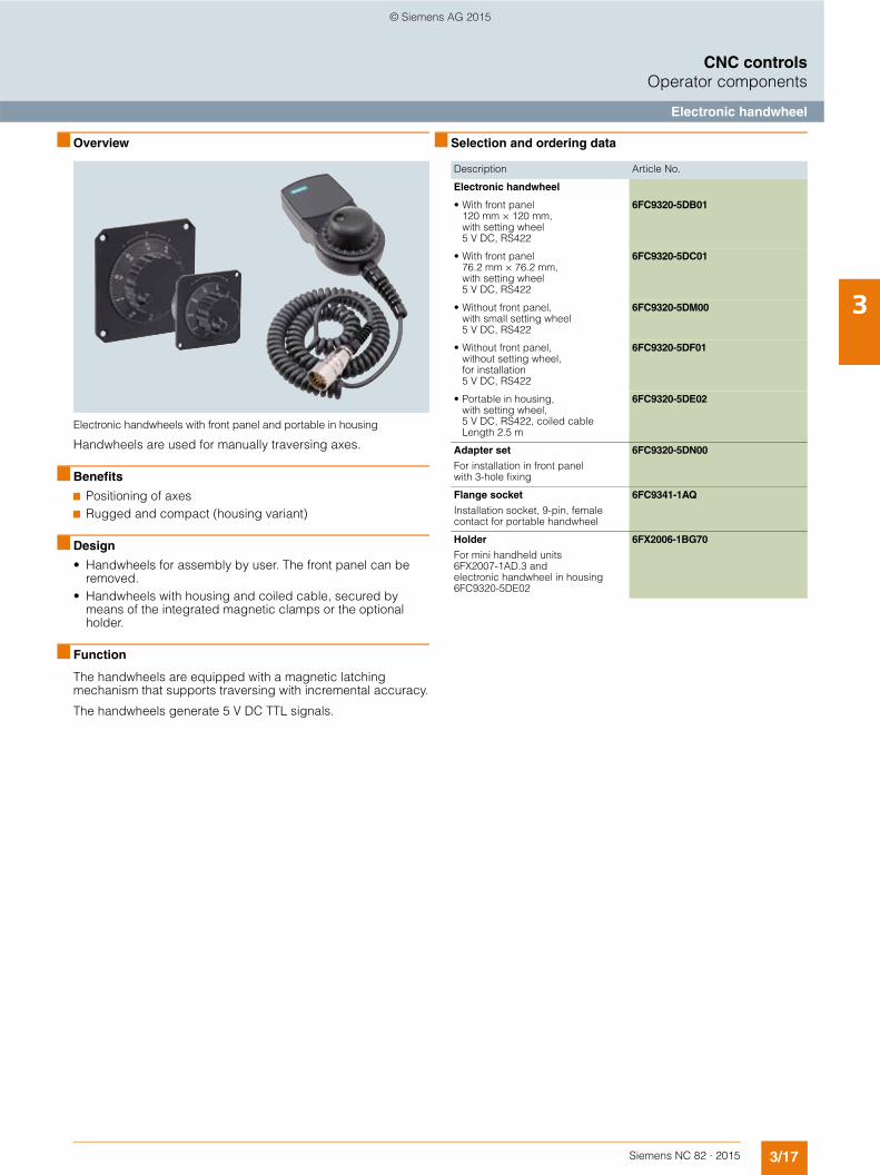
3/17Siemens NC 82 · 2015
3
CNC controlsOperator components
Electronic handwheel
■ Overview
Electronic handwheels with front panel and portable in housing
Handwheels are used for manually traversing axes.
■ Benefits
7 Positioning of axes7 Rugged and compact (housing variant)
■ Design
• Handwheels for assembly by user. The front panel can be removed.
• Handwheels with housing and coiled cable, secured by means of the integrated magnetic clamps or the optional holder.
■ Function
The handwheels are equipped with a magnetic latching mechanism that supports traversing with incremental accuracy.
The handwheels generate 5 V DC TTL signals.
■ Selection and ordering data
Description Article No.
Electronic handwheel
• With front panel 120 mm × 120 mm, with setting wheel 5 V DC, RS422
6FC9320-5DB01
• With front panel 76.2 mm × 76.2 mm, with setting wheel 5 V DC, RS422
6FC9320-5DC01
• Without front panel, with small setting wheel 5 V DC, RS422
6FC9320-5DM00
• Without front panel, without setting wheel, for installation 5 V DC, RS422
6FC9320-5DF01
• Portable in housing,with setting wheel, 5 V DC, RS422, coiled cable Length 2.5 m
6FC9320-5DE02
Adapter set
For installation in front panel with 3-hole fixing
6FC9320-5DN00
Flange socket
Installation socket, 9-pin, female contact for portable handwheel
6FC9341-1AQ
Holder
For mini handheld units 6FX2007-1AD.3 and electronic handwheel in housing 6FC9320-5DE02
6FX2006-1BG70
© Siemens AG 2015
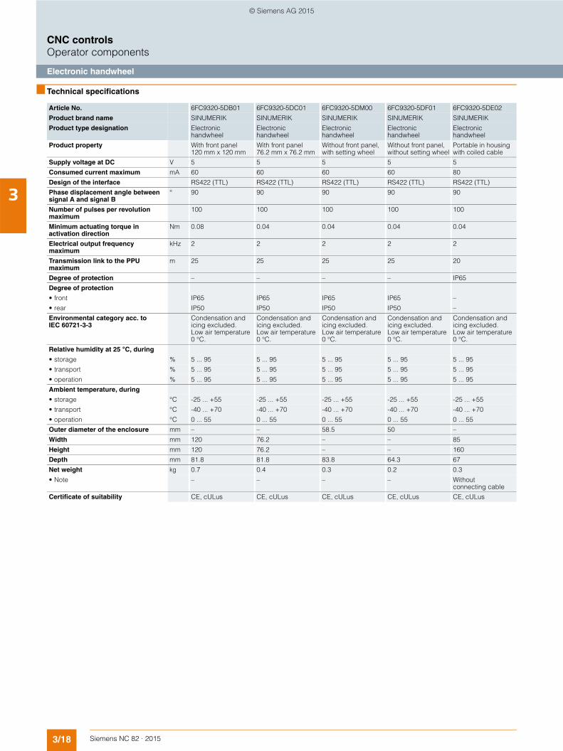
3/18 Siemens NC 82 · 2015
3
CNC controlsOperator components
Electronic handwheel
■ Technical specifications
Article No. 6FC9320-5DB01 6FC9320-5DC01 6FC9320-5DM00 6FC9320-5DF01 6FC9320-5DE02
Product brand name SINUMERIK SINUMERIK SINUMERIK SINUMERIK SINUMERIK
Product type designation Electronic handwheel
Electronic handwheel
Electronic handwheel
Electronic handwheel
Electronic handwheel
Product property With front panel 120 mm x 120 mm
With front panel 76.2 mm x 76.2 mm
Without front panel, with setting wheel
Without front panel, without setting wheel
Portable in housing with coiled cable
Supply voltage at DC V 5 5 5 5 5
Consumed current maximum mA 60 60 60 60 80
Design of the interface RS422 (TTL) RS422 (TTL) RS422 (TTL) RS422 (TTL) RS422 (TTL)
Phase displacement angle between signal A and signal B
° 90 90 90 90 90
Number of pulses per revolution maximum
100 100 100 100 100
Minimum actuating torque in activation direction
Nm 0.08 0.04 0.04 0.04 0.04
Electrical output frequency maximum
kHz 2 2 2 2 2
Transmission link to the PPU maximum
m 25 25 25 25 20
Degree of protection – – – – IP65
Degree of protection
• front IP65 IP65 IP65 IP65 –
• rear IP50 IP50 IP50 IP50 –
Environmental category acc. to IEC 60721-3-3
Condensation and icing excluded. Low air temperature 0 °C.
Condensation and icing excluded. Low air temperature 0 °C.
Condensation and icing excluded. Low air temperature 0 °C.
Condensation and icing excluded. Low air temperature 0 °C.
Condensation and icing excluded. Low air temperature 0 °C.
Relative humidity at 25 °C, during
• storage % 5 ... 95 5 ... 95 5 ... 95 5 ... 95 5 ... 95
• transport % 5 ... 95 5 ... 95 5 ... 95 5 ... 95 5 ... 95
• operation % 5 ... 95 5 ... 95 5 ... 95 5 ... 95 5 ... 95
Ambient temperature, during
• storage °C -25 ... +55 -25 ... +55 -25 ... +55 -25 ... +55 -25 ... +55
• transport °C -40 ... +70 -40 ... +70 -40 ... +70 -40 ... +70 -40 ... +70
• operation °C 0 ... 55 0 ... 55 0 ... 55 0 ... 55 0 ... 55
Outer diameter of the enclosure mm – – 58.5 50 –
Width mm 120 76.2 – – 85
Height mm 120 76.2 – – 160
Depth mm 81.8 81.8 83.8 64.3 67
Net weight kg 0.7 0.4 0.3 0.2 0.3
• Note – – – – Without connecting cable
Certificate of suitability CE, cULus CE, cULus CE, cULus CE, cULus CE, cULus
© Siemens AG 2015
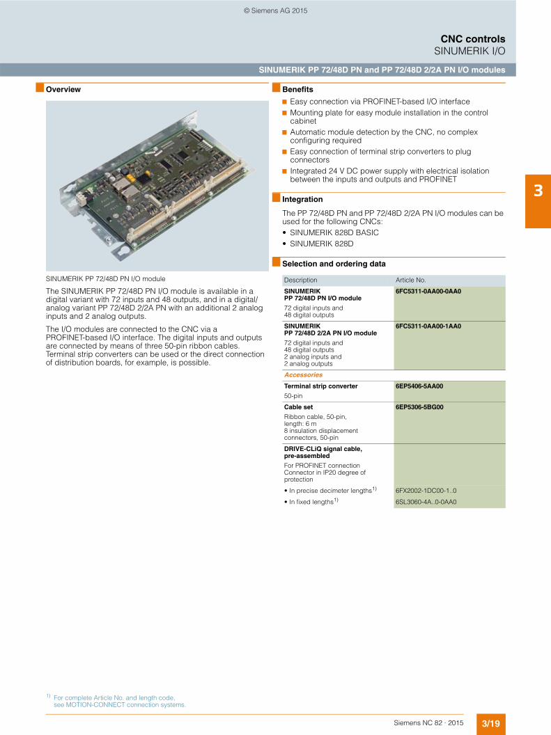
3/19Siemens NC 82 · 2015
3
CNC controlsSINUMERIK I/O
SINUMERIK PP 72/48D PN and PP 72/48D 2/2A PN I/O modules
■ Overview
SINUMERIK PP 72/48D PN I/O module
The SINUMERIK PP 72/48D PN I/O module is available in a digital variant with 72 inputs and 48 outputs, and in a digital/analog variant PP 72/48D 2/2A PN with an additional 2 analog inputs and 2 analog outputs.
The I/O modules are connected to the CNC via a PROFINET-based I/O interface. The digital inputs and outputs are connected by means of three 50-pin ribbon cables. Terminal strip converters can be used or the direct connection of distribution boards, for example, is possible.
■ Benefits
7 Easy connection via PROFINET-based I/O interface7 Mounting plate for easy module installation in the control
cabinet7 Automatic module detection by the CNC, no complex
configuring required7 Easy connection of terminal strip converters to plug
connectors7 Integrated 24 V DC power supply with electrical isolation
between the inputs and outputs and PROFINET
■ Integration
The PP 72/48D PN and PP 72/48D 2/2A PN I/O modules can be used for the following CNCs:• SINUMERIK 828D BASIC• SINUMERIK 828D
■ Selection and ordering data
Description Article No.
SINUMERIK PP 72/48D PN I/O module
72 digital inputs and 48 digital outputs
6FC5311-0AA00-0AA0
SINUMERIK PP 72/48D 2/2A PN I/O module
72 digital inputs and 48 digital outputs 2 analog inputs and 2 analog outputs
6FC5311-0AA00-1AA0
Accessories
Terminal strip converter
50-pin
6EP5406-5AA00
Cable set
Ribbon cable, 50-pin, length: 6 m8 insulation displacement connectors, 50-pin
6EP5306-5BG00
DRIVE-CLiQ signal cable, pre-assembled
For PROFINET connectionConnector in IP20 degree of protection
• In precise decimeter lengths1) 6FX2002-1DC00-1..0
• In fixed lengths1) 6SL3060-4A..0-0AA0
1) For complete Article No. and length code, see MOTION-CONNECT connection systems.
© Siemens AG 2015
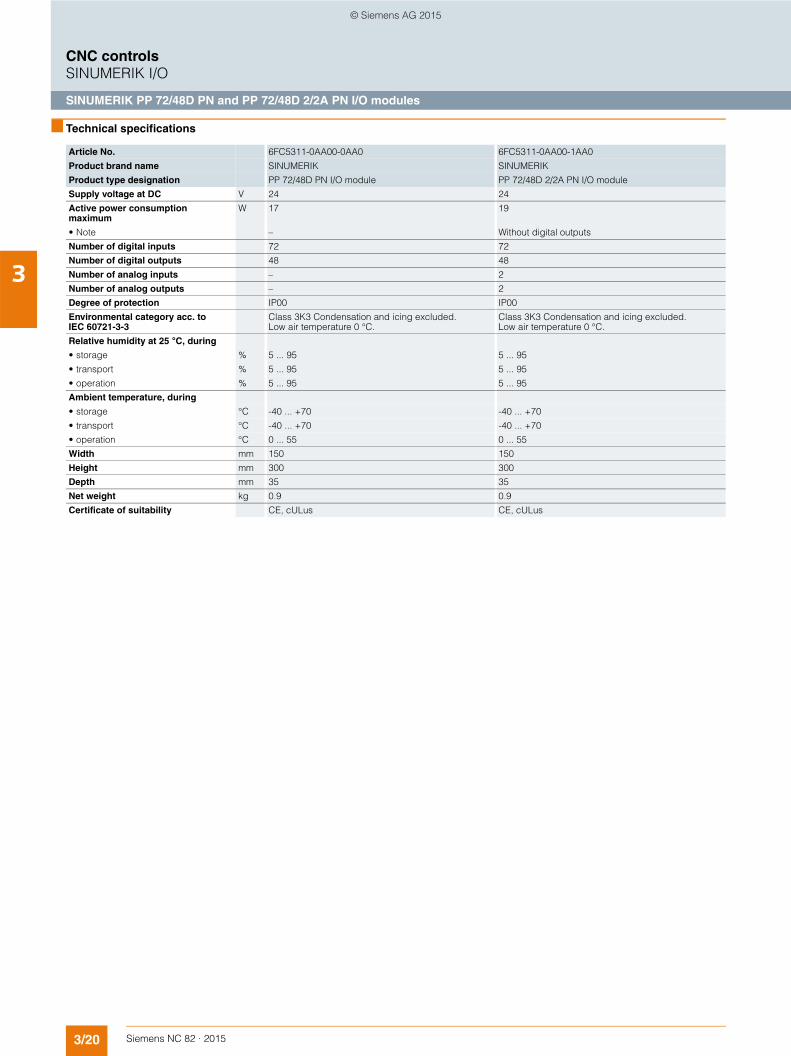
3/20 Siemens NC 82 · 2015
3
CNC controlsSINUMERIK I/O
SINUMERIK PP 72/48D PN and PP 72/48D 2/2A PN I/O modules
■ Technical specifications
Article No. 6FC5311-0AA00-0AA0 6FC5311-0AA00-1AA0
Product brand name SINUMERIK SINUMERIK
Product type designation PP 72/48D PN I/O module PP 72/48D 2/2A PN I/O module
Supply voltage at DC V 24 24
Active power consumption maximum
W 17 19
• Note – Without digital outputs
Number of digital inputs 72 72
Number of digital outputs 48 48
Number of analog inputs – 2
Number of analog outputs – 2
Degree of protection IP00 IP00
Environmental category acc. to IEC 60721-3-3
Class 3K3 Condensation and icing excluded. Low air temperature 0 °C.
Class 3K3 Condensation and icing excluded. Low air temperature 0 °C.
Relative humidity at 25 °C, during
• storage % 5 ... 95 5 ... 95
• transport % 5 ... 95 5 ... 95
• operation % 5 ... 95 5 ... 95
Ambient temperature, during
• storage °C -40 ... +70 -40 ... +70
• transport °C -40 ... +70 -40 ... +70
• operation °C 0 ... 55 0 ... 55
Width mm 150 150
Height mm 300 300
Depth mm 35 35
Net weight kg 0.9 0.9
Certificate of suitability CE, cULus CE, cULus
© Siemens AG 2015

3/21Siemens NC 82 · 2015
3
CNC controlsSupplementary components
SINAUT MD 720-3 GSM/GPRS modem
■ Overview
SINAUT MD720-3 GSM/GPRS modem
The SINAUT MD720-3 GSM/GPRS modem transmits the text messages into the GSM network of the mobile radio operator. By inserting the appropriate SIM card into the SINAUT MD720-3 GSM/GPRS modem, it is possible to freely select the required mobile radio operator.
With Easy Message the SINUMERIK 828D BASIC/828D CNCs provide a means of transmitting process data using text messages (SMS). This makes it possible to send messages to various mobile phones of the operating and maintenance personnel to notify them, for example, of the workpiece counter reading or the fact that a tool has reached its wear limit.
■ Benefits
7 Rugged GSM modem for industrial use7 High-quality signal transmission thanks to powerful external
antenna7 Simple mounting on standard mounting rails in the control
cabinet or operator panel housing
■ Design
The SINAUT MD720-3 GSM/GPRS modem features the following interfaces as standard:• 9-pin Sub-D socket for connection to the CNC
(RS232C interface)• 4-pin screw terminal for connection to a 24 V DC supply
voltage• SMA antenna connection socket for GSM/GPRS antenna• Slot for inserting a GSM SIM card
The SINAUT MD720-3 has diagnostic LEDs for modem status, field strength and connection control.
Easy Message provides the following functions:• Input of PIN number • Configuration of user profiles• Display of modem status and field strength • Generation of outgoing text messages (SMS)• Processing of incoming text messages (SMS)• Visualization of transmission protocol
■ Integration
The SINAUT MD720-3 GSM/GPRS modem can be used for the following CNCs:• SINUMERIK 828D BASIC• SINUMERIK 828D
The following components can be connected:• Modem cable for RS232C interface• SINAUT ANT 794-4MR antenna
■ Technical specifications
■ Selection and ordering data
■ More information
You can find additional information on the Internet at:
www.siemens.com/industrymall
Article No. 6NH9720-3AA00
Product brand name SINAUT
Product type designation MD720-3 GSM/GPRS modem
Supply voltage at DC 24 V
Power loss
• Typical 5 W
Transfer rate for
• GSM transmission 9600 bit/s
Interfaces
• RS232C 9-pin sub D socket connector
• Antenna SMA antenna socket (50 Ω)
Degree of protection IP40
Relative humidity at 25 °C, max. 95 %
Ambient temperature, during
• storage -25 ... +85 °C
• transport -25 ... +85 °C
• operation -20 ... +60 °C
Width 22.5 mm
Height 99 mm
Depth 114 mm
Net weight 150 g
Certificate of suitability You will find the latest approvals on the Internet at www.siemens.com/simatic-net/ik-info
Description Article No.
SINAUT MD720-3 GSM/GPRS modem
6NH9720-3AA00
SINAUT ANT 794-4MR antenna 6NH9860-1AA00
Modem cable
For RS232C interfaceLength: 2.5 m
6NH7701-5AN
© Siemens AG 2015
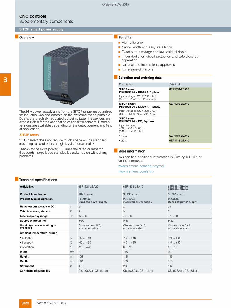
3/22 Siemens NC 82 · 2015
3
CNC controlsSupplementary components
SITOP smart power supply
■ Overview
The 24 V power supply units from the SITOP range are optimized for industrial use and operate on the switched-mode principle. Due to the precisely regulated output voltage, the devices are even suitable for the connection of sensitive sensors. Different versions are available depending on the output current and field of application.
SITOP smart
SITOP smart does not require much space on the standard mounting rail and offers a high level of functionality.
Thanks to the extra power, 1.5 times the rated current for 5 seconds, large loads can also be switched on without any problems.
■ Benefits
7 High efficiency 7 Narrow width and easy installation 7 Exact output voltage and low residual ripple7 Integrated short-circuit protection and safe electrical
separation7 National and international approvals7 No release of silicone
■ Selection and ordering data
■ More information
You can find additional information in Catalog KT 10.1 or on the Internet at:
www.siemens.com/industrymall
www.siemens.com/sitop
■ Technical specifications
Description Article No.
SITOP smart PSU100S 24 V DC/10 A, 1-phase
Input voltage: 120 V/230 V AC(85 … 132 V/170 ... 264 V AC)
6EP1334-2BA20
SITOP smart PSU100S 24 V DC/20 A, 1-phase
Input voltage: 120 V/230 V AC (85 … 132 V/176 .... 264 V AC)
6EP1336-2BA10
SITOP smart PSU300S 24 V DC, 3-phase
Input voltage: 400 ... 500 V 3 AC(340 … 550 V 3 AC)
• 10 A 6EP1434-2BA10
• 20 A 6EP1436-2BA10
Article No. 6EP1334-2BA20 6EP1336-2BA10 6EP1434-2BA10 6EP1436-2BA10
Product brand name SITOP smart SITOP smart SITOP smart
Product type designation PSU100S stabilized power supply
PSU100S stabilized power supply
PSU300S stabilized power supply
Rated output voltage at DC V 24 24 24
Total tolerance, static ± % 3 3 3
Line frequency range Hz 47 ... 63 47 ... 63 47 ... 63
Degree of protection IP20 IP20 IP20
Humidity class according to EN 60721
Climate class 3K3, no condensation
Climate class 3K3, no condensation
Climate class 3K3, no condensation
Ambient temperature, during
• storage °C -40 ... +85 -40 ... +85 -40 ... +85
• transport °C -40 ... +85 -40 ... +85 -40 ... +85
• operation °C -25 ... +70 0 ... 70 0 ... 70
Width mm 70 115 90
Height mm 125 145 145
Depth mm 120 150 150
Net weight kg 0,8 2,4 1,6
Certificate of suitability CB, cCSAus, CE, cULus CB, cCSAus, CE, cULus CB, cCSAus, CE, cULus
© Siemens AG 2015

3/23Siemens NC 82 · 2015
3
CNC controlsSupplementary components
SENTRON PAC
■ Overview
SENTRON PAC3200 Power Monitoring Device
SENTRON PAC4200 Power Monitoring Device
The 7KM PAC Power Monitoring Devices ensure precise, reproducible and reliable measurement of energy values for infeed, outgoing feeders or individual loads. The measuring devices not only supply comprehensive information about your electrical installation and power distribution system, but also provide important measured values to help you assess the status of your system and the power quality. For further process-ing of the measured data, the devices can easily be integrated into higher-level automation and energy management systems.
The devices can be used for both single-phase and multi-phase measurements in 3- and 4-conductor power supply systems (TN, TT, IT).
■ Benefits
7 Simple mounting and commissioning7 High IP65 degree of protection (front side, when installed)
permits usage in extremely dusty and wet environments7 Intuitive operation using 4 function buttons and multilingual
plain text displays7 Easy to adapt to different systems using integrated and
optional- Digital inputs and outputs- Communication interfaces
7 Global application- At least 8 languages- International approvals- Developed and tested in accordance with European and
international standards7 Low mounting depth
■ Selection and ordering data
■ More information
More information is available in the Siemens Industry Mall or on the Internet at:
www.siemens.com/industrymall
www.siemens.com/lowvoltage/powermonitoring
Description Article No.
SENTRON PAC3200 Power Monitoring Device
With screw terminals Records 50 measured values
7KM2112-0BA00-3AA0
SENTRON PAC4200Power Monitoring Device
With screw terminals Records 200 measured values
7KM4212-0BA00-3AA0
© Siemens AG 2015
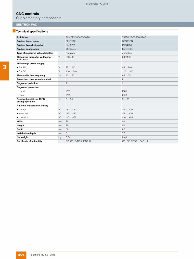
3/24 Siemens NC 82 · 2015
3
CNC controlsSupplementary components
SENTRON PAC
■ Technical specifications
Article No. 7KM2112-0BA00-3AA0 7KM4212-0BA00-3AA0
Product brand name SENTRON SENTRON
Product type designation PAC3200 PAC4200
Product designation Multimeter Multimeter
Type of measured value detection complete complete
Measuring inputs for voltage for 3 AC, max.
V 690/400 690/400
Wide-range power supply
• For AC V 95 ... 240 95 ... 240
• For DC V 110 ... 340 110 ... 340
Measurable line frequency Hz 45 ... 65 45 ... 65
Protection class when installed II II
Degree of pollution 2 2
Degree of protection
- front IP65 IP65
- rear IP20 IP20
Relative humidity at 25 °C, during operation
% 5 ... 95 5 ... 95
Ambient temperature, during
• storage °C -25 ... +70 -25 ... +70
• transport °C -25 ... +70 -25 ... +70
• operation °C -10 ... +55 -10 ... +55
Width mm 96 96
Height mm 96 96
Depth mm 56 82
Installation depth mm 51 77
Net weight kg 0.54 0.46
Certificate of suitability CB, CE, C-TICK, EAC, UL CB, CE, C-TICK, EAC, UL
© Siemens AG 2015
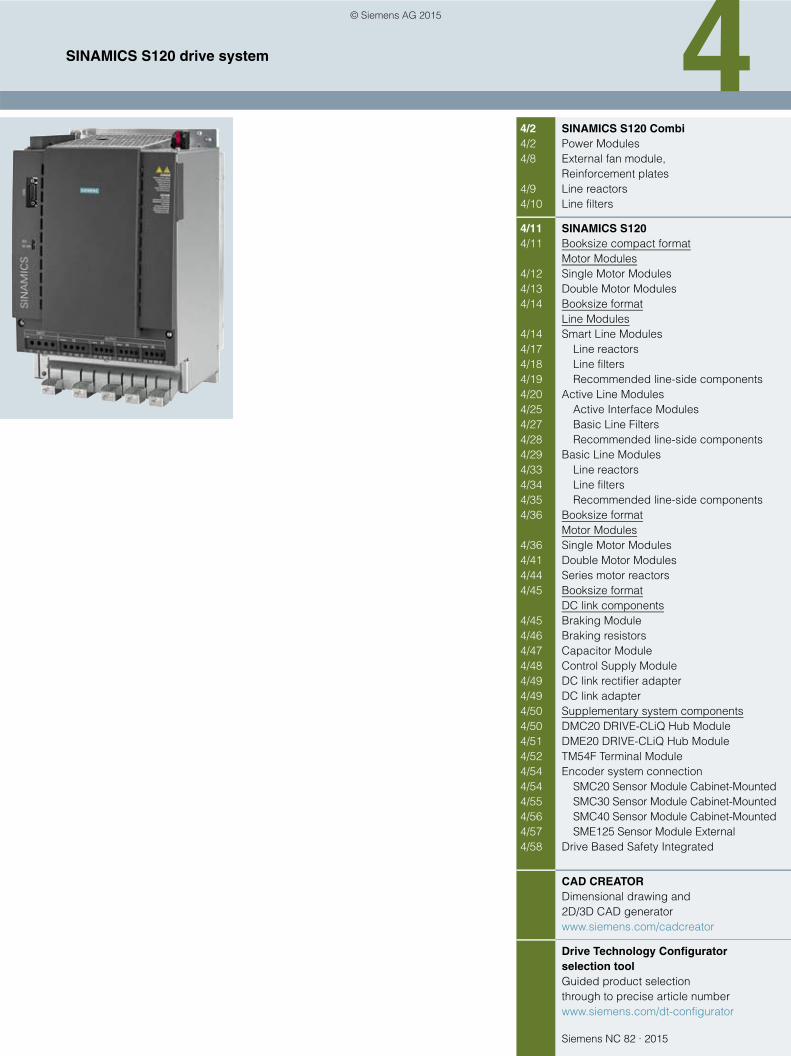
Siemens NC 82 · 2015
44/2 SINAMICS S120 Combi4/2 Power Modules4/8 External fan module,
Reinforcement plates4/9 Line reactors4/10 Line filters
4/11 SINAMICS S1204/11 Booksize compact format
Motor Modules4/12 Single Motor Modules4/13 Double Motor Modules4/14 Booksize format
Line Modules4/14 Smart Line Modules4/17 Line reactors4/18 Line filters4/19 Recommended line-side components4/20 Active Line Modules4/25 Active Interface Modules4/27 Basic Line Filters4/28 Recommended line-side components4/29 Basic Line Modules4/33 Line reactors4/34 Line filters4/35 Recommended line-side components4/36 Booksize format
Motor Modules4/36 Single Motor Modules4/41 Double Motor Modules4/44 Series motor reactors4/45 Booksize format
DC link components4/45 Braking Module4/46 Braking resistors4/47 Capacitor Module4/48 Control Supply Module4/49 DC link rectifier adapter4/49 DC link adapter4/50 Supplementary system components4/50 DMC20 DRIVE-CLiQ Hub Module4/51 DME20 DRIVE-CLiQ Hub Module4/52 TM54F Terminal Module4/54 Encoder system connection4/54 SMC20 Sensor Module Cabinet-Mounted4/55 SMC30 Sensor Module Cabinet-Mounted4/56 SMC40 Sensor Module Cabinet-Mounted4/57 SME125 Sensor Module External4/58 Drive Based Safety Integrated
CAD CREATORDimensional drawing and2D/3D CAD generatorwww.siemens.com/cadcreator
Drive Technology Configuratorselection toolGuided product selectionthrough to precise article numberwww.siemens.com/dt-configurator
SINAMICS S120 drive system
© Siemens AG 2015

4/2 Siemens NC 82 · 2015
SINAMICS S120 drive systemSINAMICS S120 Combi
Power Modules
4
■ Overview
SINAMICS S120 Combi Power Module
SINAMICS S120 Combi is a very compact and rugged drive concept tailored for compact turning and milling machines. SINAMICS S120 Combi integrates a line infeed with regenerative feedback capability, power units for spindle and feed motors as well as a TTL encoder interface into a single Power Module. The SINAMICS S120 Combi Power Modules are optimized as a drive for machine tools with 3 to 6 axes. The Power Modules are avail-able with external air cooling. SINAMICS Motor Modules in the booksize compact format are used as expansion axes.
■ Benefits
7 Compact multi-axis module with line infeed with regenerative feedback capability and power units for 3 or 4 axes
7 Customized drive system for compact standard turning and milling machines
7 Requires very little mounting space in control cabinet (incl. fan module, shield terminals and ventilation clearances)
7 Optimized for weak supply networks with frequent undervolt-age, network imbalances and large frequency fluctuations
7 Optimized for harsh operating conditions with increased cabinet temperature and increased humidity
7 Rugged Power Modules resistant to short circuits, overvoltage and ground faults
7 Rugged and easy-to-fit screw-type terminals with integrated shield connection for the power cables
7 Perfect expandability using additional Motor Modules in booksize compact format
7 Low energy consumption thanks to state-of-the-art 400-V technology
7 Excellent dynamic response and machining precision thanks to Dynamic Servo Control (DSC)
7 Simple cabling due to intelligent DRIVE-CLiQ interface7 Very simple commissioning thanks to predefined topologies
■ Function
• Power Module with 3 or 4 integrated power units• Integrated line infeed with regenerative feedback capability• Integrated TTL encoder interface• Integrated motor brake control for one axis• Integrated fan power supply• Line supply voltage 380 to 480 V 3 AC• Supply types TT, TN and IT• Integrated shield terminals• Heat dissipation concept with an external heatsink for
extremely low power loss in the control cabinet• Easy-to-mount fan module optimized for harsh environments• Increased availability thanks to fan monitoring• Derating only from 45 °C cabinet temperature • Power cables are connected by means of screw-type
terminals
■ Integration
The following components can be connected to the SINAMICS S120 Combi drive system:• SINUMERIK 828D BASIC• SINUMERIK 828D • 3 or 4 spindles/feed motors• 3 or 4 motor encoders• 3 or 4 direct encoders via DMC20• Direct spindle encoder with TTL directly or sin/cos via SMC20• External fan module• Up to two additional SINAMICS S120 Motor Modules in
booksize compact format via DC link connection and 24 V DC busbars
• Braking Module with braking resistor via DC link connection• Control Supply Module via DC link connection and
24 V DC busbars• One safe motor brake control• 5 or 6 DRIVE-CLiQ sockets• 24 V electronics power supply via connector• 1 safe standstill input for the infeed (Enable Pulses)• 1 safe standstill input for the spindle and feeds
(Enable Pulses)• 1 temperature sensor input for the spindle
(KTY84-130 or PTC)• PE/protective conductor connections
The scope of supply of the SINAMICS S120 Combi Power Modules includes:• SINAMICS S120 Combi Power Module• Accessories pack consisting of:
- 4 DRIVE-CLiQ dust-proof blanking plugs- Connector X224 for the electronics power supply- Connector X11 for motor brake control- Connector X21 Enable Pulses infeed- Connector X22 Enable Pulses drives/temp.- 5 shield terminals for power cables- Shield terminal for signal cable
© Siemens AG 2015
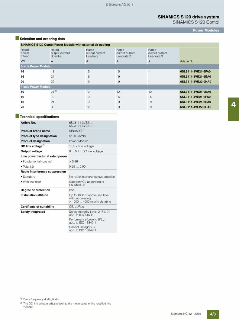
4/3Siemens NC 82 · 2015
SINAMICS S120 drive systemSINAMICS S120 Combi
Power Modules
4
■ Selection and ordering data
■ Technical specifications
SINAMICS S120 Combi Power Module with external air cooling
Rated power Infeed
Rated output currentSpindle
Rated output current Feedrate 1
Rated output current Feedrate 2
Rated output current Feedrate 3
kW A A A A Article No.
3-axis Power Module
16 18 5 5 – 6SL3111-3VE21-6FA0
16 24 9 9 – 6SL3111-3VE21-6EA0
20 30 9 9 – 6SL3111-3VE22-0HA0
4-axis Power Module
10 24 1) 12 12 12 6SL3111-4VE21-0EA0
16 18 9 5 5 6SL3111-4VE21-6FA0
16 24 9 9 9 6SL3111-4VE21-6EA0
20 30 12 9 9 6SL3111-4VE22-0HA0
Article No. 6SL3111-3VE2.-....6SL3111-4VE2.-....
Product brand name SINAMICS
Product type designation S120 Combi
Product designation Power Module
DC link voltage2) 1.35 × line voltage
Output voltage 0 ... 0.7 × DC link voltage
Line power factor at rated power
• Fundamental (cos ϕ1) > 0.96
• Total (λ) 0.65 … 0.90
Radio interference suppression
• Standard No radio interference suppression
• With line filter Category C2 according to EN 61800-3
Degree of protection IP20
Installation altitude Up to 1000 m above sea level without derating, > 1000 ... 4000 m with derating
Certificate of suitability CE, cURus
Safety Integrated Safety Integrity Level 2 (SIL 2) acc. to IEC 61508Performance Level d (PLd) acc. to ISO 13849-1Control Category 3 acc. to ISO 13849-1
1) Pulse frequency 4 kHz/8 kHz.2) The DC link voltage adjusts itself to the mean value of the rectified line
voltage.
© Siemens AG 2015

4/4 Siemens NC 82 · 2015
SINAMICS S120 drive systemSINAMICS S120 Combi
Power Modules
4
■ Technical specifications (continued)
Article No. 6SL3111-3VE21-6FA0 6SL3111-3VE21-6EA0 6SL3111-3VE22-0HA0
Product designation 3-axis Power Module with external air cooling
Infeed
• Rated power Prated (S1) kW 16 16 20
• Infeed power PS6 (S6-40 %) kW 21 21 26.5
• Peak infeed power Pmax kW 35 35 40
Regenerative feedback
• Rated power Prated (S1) kW 16 16 20
• Peak regenerative feedback power Pmax
kW 35 35 40
Supply voltages
• Line voltage 3 AC V 380 -10 % ... 480 +10 %
• Line frequency Hz 45 ... 66
• Electronics power supply DC V 24 (20.4 ... 28.8)
Rated input current
• At 400 V 3 AC A 28 28 34
• At 380 V/480 V 3 AC A 29/25 29/25 35/30
• At 400 V 3 AC (S6-40 %) A 35.5 35.5 44
• At 400 V 3 AC peak current A 56 56 63.5
Pulse frequency kHz 4 4 4
Output voltage AC V 0 ... 0.7 × DC link voltage
Spindle
• Rated output current AC Irated A 18 24 30
• Base-load current AC IH A 15.3 20.4 25.5
• Intermittent-duty operating current AC IS6-40 %
A 24 32 40
• Peak current AC Imax A 36 48 56
Rated power
• At 540 V DC link voltage kW 8.7 11.7 14.4
• At 600 V DC link voltage kW 9.7 13 16
Feedrate 1/Feedrate 2
• Rated output current AC Irated A 5 9 9
• Base-load current AC IH A 4.3 7.7 7.7
• Intermittent-duty operating current AC IS6-40 %
A 6.5 12 12
• Peak current AC Imax A 10 18 18
Rated power
• At 540 V DC link voltage kW 2.4 4.3 4.3
• At 600 V DC link voltage kW 2.7 4.8 4.8
Output for expansion axis
• DC link output current DC Irated A 40 40 40
• DC link voltage DC V 460 ... 720 460 ... 720 460 ... 720
• Electronics output current for an expansion axis 24 V DC
A 20 20 20
Electronics current consumption at 24 V DC
• Without external fan module A 1.5 1.5 1.5
• With external fan module A 2.3 2.3 2.3
Total power loss incl. electronics losses
W 425 537 634
• Internal W 81 91 102
• External W 344 446 532
© Siemens AG 2015
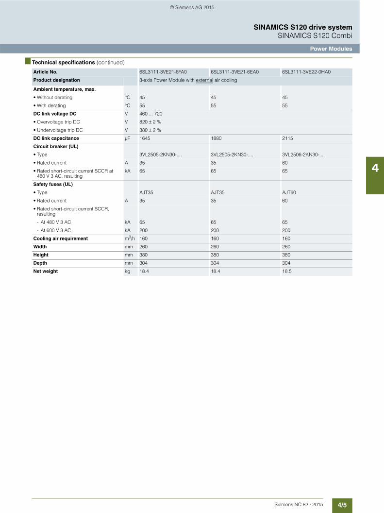
4/5Siemens NC 82 · 2015
SINAMICS S120 drive systemSINAMICS S120 Combi
Power Modules
4
■ Technical specifications (continued)
Article No. 6SL3111-3VE21-6FA0 6SL3111-3VE21-6EA0 6SL3111-3VE22-0HA0
Product designation 3-axis Power Module with external air cooling
Ambient temperature, max.
• Without derating °C 45 45 45
• With derating °C 55 55 55
DC link voltage DC V 460 ... 720
• Overvoltage trip DC V 820 ± 2 %
• Undervoltage trip DC V 380 ± 2 %
DC link capacitance µF 1645 1880 2115
Circuit breaker (UL)
• Type 3VL2505-2KN30-.... 3VL2505-2KN30-.... 3VL2506-2KN30-....
• Rated current A 35 35 60
• Rated short-circuit current SCCR at 480 V 3 AC, resulting
kA 65 65 65
Safety fuses (UL)
• Type AJT35 AJT35 AJT60
• Rated current A 35 35 60
• Rated short-circuit current SCCR, resulting
- At 480 V 3 AC kA 65 65 65
- At 600 V 3 AC kA 200 200 200
Cooling air requirement m3/h 160 160 160
Width mm 260 260 260
Height mm 380 380 380
Depth mm 304 304 304
Net weight kg 18.4 18.4 18.5
© Siemens AG 2015
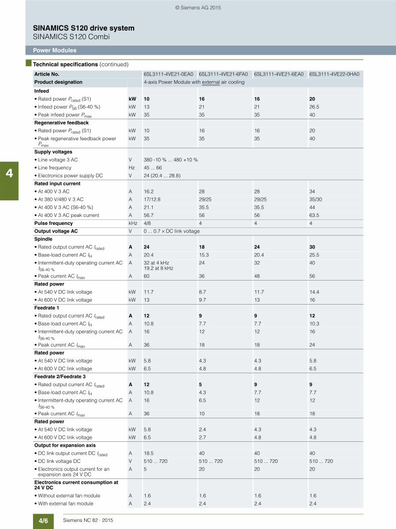
4/6 Siemens NC 82 · 2015
SINAMICS S120 drive systemSINAMICS S120 Combi
Power Modules
4
■ Technical specifications (continued)
Article No. 6SL3111-4VE21-0EA0 6SL3111-4VE21-6FA0 6SL3111-4VE21-6EA0 6SL3111-4VE22-0HA0
Product designation 4-axis Power Module with external air cooling
Infeed
• Rated power Prated (S1) kW 10 16 16 20
• Infeed power PS6 (S6-40 %) kW 13 21 21 26.5
• Peak infeed power Pmax kW 35 35 35 40
Regenerative feedback
• Rated power Prated (S1) kW 10 16 16 20
• Peak regenerative feedback power Pmax
kW 35 35 35 40
Supply voltages
• Line voltage 3 AC V 380 -10 % ... 480 +10 %
• Line frequency Hz 45 ... 66
• Electronics power supply DC V 24 (20.4 ... 28.8)
Rated input current
• At 400 V 3 AC A 16.2 28 28 34
• At 380 V/480 V 3 AC A 17/12.8 29/25 29/25 35/30
• At 400 V 3 AC (S6-40 %) A 21.1 35.5 35.5 44
• At 400 V 3 AC peak current A 56.7 56 56 63.5
Pulse frequency kHz 4/8 4 4 4
Output voltage AC V 0 ... 0.7 × DC link voltage
Spindle
• Rated output current AC Irated A 24 18 24 30
• Base-load current AC IH A 20.4 15.3 20.4 25.5
• Intermittent-duty operating current AC IS6-40 %
A 32 at 4 kHz19.2 at 8 kHz
24 32 40
• Peak current AC Imax A 60 36 48 56
Rated power
• At 540 V DC link voltage kW 11.7 8.7 11.7 14.4
• At 600 V DC link voltage kW 13 9.7 13 16
Feedrate 1
• Rated output current AC Irated A 12 9 9 12
• Base-load current AC IH A 10.8 7.7 7.7 10.3
• Intermittent-duty operating current AC IS6-40 %
A 16 12 12 16
• Peak current AC Imax A 36 18 18 24
Rated power
• At 540 V DC link voltage kW 5.8 4.3 4.3 5.8
• At 600 V DC link voltage kW 6.5 4.8 4.8 6.5
Feedrate 2/Feedrate 3
• Rated output current AC Irated A 12 5 9 9
• Base-load current AC IH A 10.8 4.3 7.7 7.7
• Intermittent-duty operating current AC IS6-40 %
A 16 6.5 12 12
• Peak current AC Imax A 36 10 18 18
Rated power
• At 540 V DC link voltage kW 5.8 2.4 4.3 4.3
• At 600 V DC link voltage kW 6.5 2.7 4.8 4.8
Output for expansion axis
• DC link output current DC Irated A 18.5 40 40 40
• DC link voltage DC V 510 ... 720 510 ... 720 510 ... 720 510 ... 720
• Electronics output current for an expansion axis 24 V DC
A 5 20 20 20
Electronics current consumption at 24 V DC
• Without external fan module A 1.6 1.6 1.6 1.6
• With external fan module A 2.4 2.4 2.4 2.4
© Siemens AG 2015
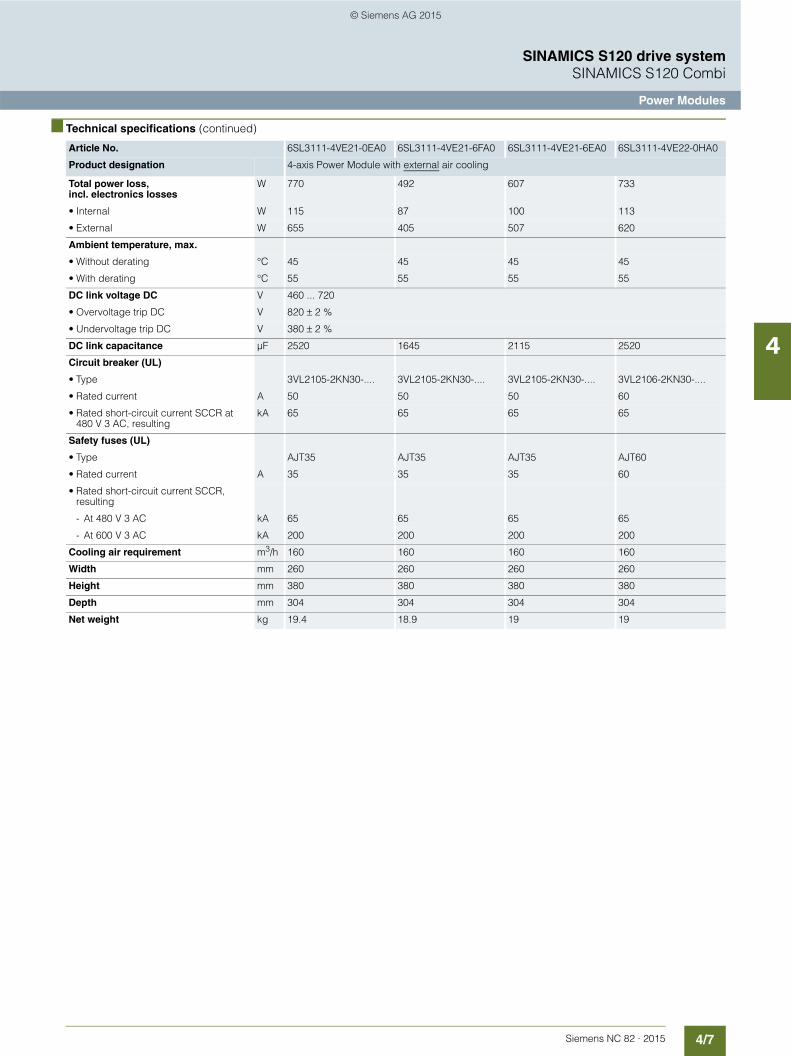
4/7Siemens NC 82 · 2015
SINAMICS S120 drive systemSINAMICS S120 Combi
Power Modules
4
■ Technical specifications (continued)
Article No. 6SL3111-4VE21-0EA0 6SL3111-4VE21-6FA0 6SL3111-4VE21-6EA0 6SL3111-4VE22-0HA0
Product designation 4-axis Power Module with external air cooling
Total power loss, incl. electronics losses
W 770 492 607 733
• Internal W 115 87 100 113
• External W 655 405 507 620
Ambient temperature, max.
• Without derating °C 45 45 45 45
• With derating °C 55 55 55 55
DC link voltage DC V 460 ... 720
• Overvoltage trip DC V 820 ± 2 %
• Undervoltage trip DC V 380 ± 2 %
DC link capacitance µF 2520 1645 2115 2520
Circuit breaker (UL)
• Type 3VL2105-2KN30-.... 3VL2105-2KN30-.... 3VL2105-2KN30-.... 3VL2106-2KN30-....
• Rated current A 50 50 50 60
• Rated short-circuit current SCCR at 480 V 3 AC, resulting
kA 65 65 65 65
Safety fuses (UL)
• Type AJT35 AJT35 AJT35 AJT60
• Rated current A 35 35 35 60
• Rated short-circuit current SCCR, resulting
- At 480 V 3 AC kA 65 65 65 65
- At 600 V 3 AC kA 200 200 200 200
Cooling air requirement m3/h 160 160 160 160
Width mm 260 260 260 260
Height mm 380 380 380 380
Depth mm 304 304 304 304
Net weight kg 19.4 18.9 19 19
© Siemens AG 2015
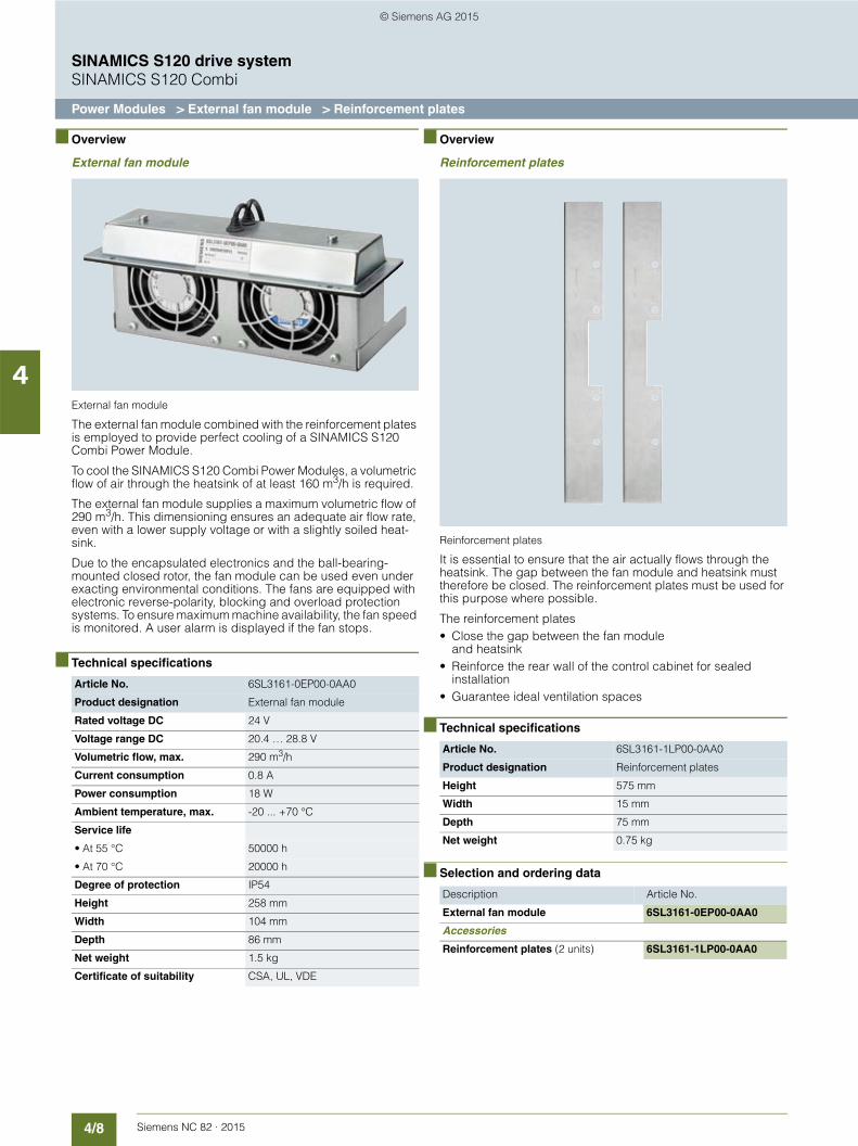
4/8 Siemens NC 82 · 2015
SINAMICS S120 drive systemSINAMICS S120 Combi
Power Modules > External fan module > Reinforcement plates
4
■ Overview
External fan module
External fan module
The external fan module combined with the reinforcement plates is employed to provide perfect cooling of a SINAMICS S120 Combi Power Module.
To cool the SINAMICS S120 Combi Power Modules, a volumetric flow of air through the heatsink of at least 160 m3/h is required.
The external fan module supplies a maximum volumetric flow of 290 m3/h. This dimensioning ensures an adequate air flow rate, even with a lower supply voltage or with a slightly soiled heat-sink.
Due to the encapsulated electronics and the ball-bearing-mounted closed rotor, the fan module can be used even under exacting environmental conditions. The fans are equipped with electronic reverse-polarity, blocking and overload protection systems. To ensure maximum machine availability, the fan speed is monitored. A user alarm is displayed if the fan stops.
■ Technical specifications
■ Overview
Reinforcement plates
Reinforcement plates
It is essential to ensure that the air actually flows through the heatsink. The gap between the fan module and heatsink must therefore be closed. The reinforcement plates must be used for this purpose where possible.
The reinforcement plates• Close the gap between the fan module
and heatsink• Reinforce the rear wall of the control cabinet for sealed
installation• Guarantee ideal ventilation spaces
■ Technical specifications
■ Selection and ordering data
Article No. 6SL3161-0EP00-0AA0
Product designation External fan module
Rated voltage DC 24 V
Voltage range DC 20.4 … 28.8 V
Volumetric flow, max. 290 m3/h
Current consumption 0.8 A
Power consumption 18 W
Ambient temperature, max. -20 ... +70 °C
Service life
• At 55 °C 50000 h
• At 70 °C 20000 h
Degree of protection IP54
Height 258 mm
Width 104 mm
Depth 86 mm
Net weight 1.5 kg
Certificate of suitability CSA, UL, VDE
Article No. 6SL3161-1LP00-0AA0
Product designation Reinforcement plates
Height 575 mm
Width 15 mm
Depth 75 mm
Net weight 0.75 kg
Description Article No.
External fan module 6SL3161-0EP00-0AA0
Accessories
Reinforcement plates (2 units) 6SL3161-1LP00-0AA0
© Siemens AG 2015

4/9Siemens NC 82 · 2015
SINAMICS S120 drive systemSINAMICS S120 Combi
Power Modules > Line reactors
4
■ Overview
Line reactor
SINAMICS S120 Combi Power Modules cannot operate without line reactors.
The use of other makes of line reactor can lead to malfunctions or irreparable damage to equipment.
■ Selection and ordering data
■ Technical specifications
Suitable for SINAMICS S120 Combi
SINAMICS line reactor
Rated powerInfeed
Power Module Rated power
kW Type kW Article No.
16 16 10 16 16
6SL3111-3VE21-6FA0 6SL3111-3VE21-6EA0 6SL3111-4VE21-0EA0 6SL3111-4VE21-6FA0 6SL3111-4VE21-6EA0
16 6SL3100-0EE21-6AA0
20 20
6SL3111-3VE22-0HA0 6SL3111-4VE22-0HA0
20 6SL3100-0EE22-0AA0
Article No. 6SL3100-0EE21-6AA0 6SL3100-0EE22-0AA0
Product designation Line reactor Line reactor
Rated power kW 16 20
Rated current A 28 33
Power loss W 75 98
Line/load connection1U1, 1V1, 1W1/1U2, 1V2, 1W2
Screw-type terminals Screw-type terminals
• Conductor cross-section mm2 4 10
PE connection Screw-type terminals Screw-type terminals
• Conductor cross-section mm2 4 10
Degree of protection IP20 IP20
Width mm 219 219
Height mm 176 176
Depth mm 120 130
Net weight kg 10.7 10.9
Certificate of suitability cURus cURus
© Siemens AG 2015
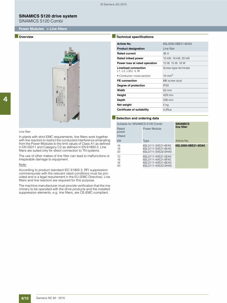
4/10 Siemens NC 82 · 2015
SINAMICS S120 drive systemSINAMICS S120 Combi
Power Modules > Line filters
4
■ Overview
Line filter
In plants with strict EMC requirements, line filters work together with line reactors to restrict the conducted interference emanating from the Power Modules to the limit values of Class A1 as defined in EN 55011 and Category C2 as defined in EN 61800-3. Line filters are suited only for direct connection to TN systems.
The use of other makes of line filter can lead to malfunctions or irreparable damage to equipment.
Note:
According to product standard IEC 61800 3, RFI suppression commensurate with the relevant rated conditions must be pro-vided and is a legal requirement in the EU (EMC Directive). Line filters and line reactors are required for this purpose.
The machine manufacturer must provide verification that the ma-chinery to be operated with the drive products and the installed suppression elements, e.g. line filters, are CE-EMC-compliant.
■ Technical specifications
■ Selection and ordering data
Article No. 6SL3000-0BE21-6DA0
Product designation Line filter
Rated current 36 A
Rated infeed power 10 kW, 16 kW, 20 kW
Power loss at rated operation 12 W, 15 W, 16 W
Line/load connectionL1, L2, L3/U, V, W
Screw-type terminals
• Conductor cross-section 10 mm2
PE connection M6 screw stud
Degree of protection IP20
Width 50 mm
Height 429 mm
Depth 226 mm
Net weight 5 kg
Certificate of suitability cURus
Suitable for SINAMICS S120 Combi SINAMICSline filter
Rated powerInfeed
Power Module
kW Type Article No.
16 16 20
6SL3111-3VE21-6FA0 6SL3111-3VE21-6EA0 6SL3111-3VE22-0HA0
6SL3000-0BE21-6DA0
10 16 16 20
6SL3111-4VE21-0EA0 6SL3111-4VE21-6FA0 6SL3111-4VE21-6EA0 6SL3111-4VE22-0HA0
© Siemens AG 2015
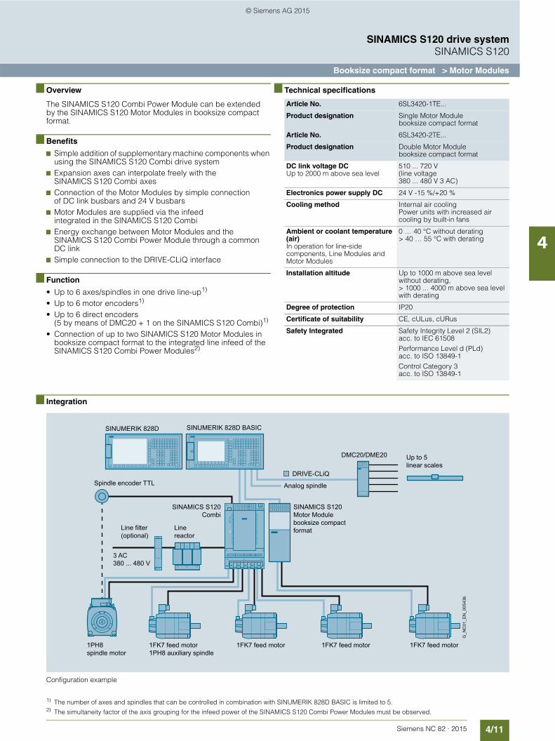
4/11Siemens NC 82 · 2015
SINAMICS S120 drive systemSINAMICS S120
Booksize compact format > Motor Modules
4
■ Overview
The SINAMICS S120 Combi Power Module can be extended by the SINAMICS S120 Motor Modules in booksize compact format.
■ Benefits
7 Simple addition of supplementary machine components when using the SINAMICS S120 Combi drive system
7 Expansion axes can interpolate freely with the SINAMICS S120 Combi axes
7 Connection of the Motor Modules by simple connection of DC link busbars and 24 V busbars
7 Motor Modules are supplied via the infeed integrated in the SINAMICS S120 Combi
7 Energy exchange between Motor Modules and the SINAMICS S120 Combi Power Module through a common DC link
7 Simple connection to the DRIVE-CLiQ interface
■ Function
• Up to 6 axes/spindles in one drive line-up1)
• Up to 6 motor encoders1)
• Up to 6 direct encoders (5 by means of DMC20 + 1 on the SINAMICS S120 Combi)1)
• Connection of up to two SINAMICS S120 Motor Modules in booksize compact format to the integrated line infeed of the SINAMICS S120 Combi Power Modules2)
■ Technical specifications
■ Integration
Configuration example
Article No. 6SL3420-1TE...
Product designation Single Motor Modulebooksize compact format
Article No. 6SL3420-2TE...
Product designation Double Motor Modulebooksize compact format
DC link voltage DCUp to 2000 m above sea level
510 ... 720 V(line voltage380 ... 480 V 3 AC)
Electronics power supply DC 24 V -15 %/+20 %
Cooling method Internal air coolingPower units with increased air cooling by built-in fans
Ambient or coolant temperature (air)In operation for line-side components, Line Modules and Motor Modules
0 … 40 °C without derating> 40 … 55 °C with derating
Installation altitude Up to 1000 m above sea level without derating,> 1000 ... 4000 m above sea level with derating
Degree of protection IP20
Certificate of suitability CE, cULus, cURus
Safety Integrated Safety Integrity Level 2 (SIL2) acc. to IEC 61508Performance Level d (PLd) acc. to ISO 13849-1Control Category 3 acc. to ISO 13849-1
DRIVE-CLiQ
SINAMICS S120Motor Module booksize compact format
1FK7 feed motor 1FK7 feed motor 1FK7 feed motor1FK7 feed motor1PH8 auxiliary spindle
1PH8 spindle motor
3 AC380 ... 480 V
SINAMICS S120Combi
Line reactor
Line filter (optional)
Spindle encoder TTL
Up to 5 linear scales
DMC20/DME20G
_NC
01_E
N_0
0543
b
Analog spindle
SINUMERIK 828D BASIC SINUMERIK 828D
1) The number of axes and spindles that can be controlled in combination with SINUMERIK 828D BASIC is limited to 5.2) The simultaneity factor of the axis grouping for the infeed power of the SINAMICS S120 Combi Power Modules must be observed.
© Siemens AG 2015

4/12 Siemens NC 82 · 2015
SINAMICS S120 drive systemSINAMICS S120
Booksize compact format > Single Motor Modules
4
■ Design
Single Motor Modules in booksize compact format
The Single Motor Modules in booksize compact format feature the following connections and interfaces as standard:• 2 DC link connections via integrated DC link busbars• 1 electronics power supply connection via integrated
24 V DC bars• 3 DRIVE-CLiQ sockets• 1 motor connection via connector• 1 safe standstill input (Enable Pulses)• 1 safe motor brake control• 1 temperature sensor input (KTY84-130 or PTC)• 2 PE/protective conductor connections
■ Design (continued)
The status of the Motor Modules is indicated via two multi-color LEDs.
The shield of the motor cable is routed over the connector to the motor connection.
The signal cable shield can be connected to the Motor Module by means of a shield terminal, e.g. type KLBÜ 3-8 SC by Weidmüller.
The scope of supply of the Motor Modules includes: • DRIVE-CLiQ cable appropriate to the width of the Motor
Module for connection to the adjacent Motor Module,length 0.11 m for 50 mm wide Motor Modules orlength 0.16 m for 75 mm wide Motor Modules.
• 2 blanking plugs for sealing unused DRIVE-CLiQ sockets
• Jumper for connecting the 24 V DC busbar to the adjacent Motor Module
• Connector X21• Connector X11 for motor brake connection• Connector X1 for motor connection• 1 set of warning labels in 30 languages• 1 heat conducting foil
■ Selection and ordering data
■ Technical specifications
SINAMICS S120Single Motor Modules in booksize compact format
Rated output current
Rated power
Internal air cooling
A kW Article No.
DC link voltage 510 … 720 V DC
3 1.6 6SL3420-1TE13-0AA1
5 2.7 6SL3420-1TE15-0AA1
9 4.8 6SL3420-1TE21-0AA1
18 9.7 6SL3420-1TE21-8AA1
Article No. 6SL3420-1TE13-0AA1 6SL3420-1TE15-0AA1 6SL3420-1TE21-0AA1 6SL3420-1TE21-8AA1
Product designation Single Motor Modules in booksize compact format with internal air cooling
DC link voltage 510 … 720 V DC
Output current
• Rated current Irated A 3 5 9 18
• Imax A 9 15 27 54
Rated power kW 1.6 2.7 4.8 9.7
DC link current Id1) A 3.6 6 11 22
Current requirement at 24 V DC, max.
A 0.85 0.85 0.85 0.85
Power loss2)
• With internal air cooling in control cabinet
W 70 100 100 180
Width mm 50 50 50 75
Height mm 270 270 270 270
Depth mm 226 226 226 226
Net weight kg 2.7 2.7 2.7 3.4
1) Rated DC link current for dimensioning an external DC connection.2) Power loss of Motor Module at rated power including losses of 24 V DC electronics power supply.
© Siemens AG 2015

4/13Siemens NC 82 · 2015
SINAMICS S120 drive systemSINAMICS S120
Booksize compact format > Double Motor Modules
4
■ Design
Double Motor Modules in booksize compact format
The Double Motor Modules in booksize compact format feature the following connections and interfaces as standard:• 2 DC link connections via integrated DC link busbars• 2 electronics power supply connections via integrated
24 V DC bars• 4 DRIVE-CLiQ sockets• 2 motor connections via connector• 2 safe standstill inputs (1 input per axis)• 2 safe motor brake controls• 2 temperature sensor inputs (KTY84-130 or PTC)• 3 PE/protective conductor connections
■ Design (continued)
The status of the Motor Modules is indicated via two multi-color LEDs.
The shield of the motor cables is routed over the connectors to the motor connection.
The signal cable shield can be connected to the Motor Module by means of a shield terminal, e.g. type KLBÜ 3-8 SC by Weidmüller.
The scope of supply of the Motor Modules includes: • DRIVE-CLiQ cable for connection to the adjacent Motor
Module, length 0.16 m• 2 blanking plugs for sealing unused DRIVE-CLiQ sockets• Jumper for connecting the 24 V DC busbar to the adjacent
Motor Module• Connectors X21 and X22• Connectors X1 and X2 for motor connection• 1 set of warning labels in 30 languages• 1 heat conducting foil
■ Selection and ordering data
■ Technical specifications
1) Rated DC link current for dimensioning an external DC connection.2) Power loss of Motor Module at rated power including losses of 24 V DC electronics power supply.
SINAMICS S120Double Motor Modules in booksize compact format
Rated output current
Rated power
Internal air cooling
A kW Article No.
DC link voltage 510 … 720 V DC
2 × 1.7 2 × 0.9 6SL3420-2TE11-7AA1
2 × 3 2 × 1.6 6SL3420-2TE13-0AA1
2 × 5 2 × 2.7 6SL3420-2TE15-0AA1
Article No. 6SL3420-2TE11-7AA1 6SL3420-2TE13-0AA1 6SL3420-2TE15-0AA1
Product designation Double Motor Modules in booksize compact format with internal air cooling
DC link voltage 510 … 720 V DC
Output current
• Rated current Irated A 2 × 1.7 2 × 3 2 × 5
• Imax A 2 × 5.1 2 × 9 2 × 15
Rated power kW 2 × 0.9 2 × 1.6 2 × 2.7
DC link current Id1) A 4.1 7.2 12
Power loss2)
• With internal air cooling in control cabinet
W 110 130 190
Width mm 75 75 75
Height mm 270 270 270
Depth mm 226 226 226
Net weight kg 3.4 3.4 3.4
© Siemens AG 2015

4/14 Siemens NC 82 · 2015
SINAMICS S120 drive systemSINAMICS S120
Booksize format > Line Modules > Smart Line Modules
4
■ Overview 1)
Smart Line Module
Smart Line Modules are non-regulated, line-commutated feed/feedback units (diode bridge for incoming supply; line-commu-tated feedback via IGBTs) with 100 % continuous regenerative feedback power. The regenerative feedback capability of the modules can be deactivated by means of a digital input (Smart Line Modules 5 kW and 10 kW) or by means of parameterization (Smart Line Modules 16 kW, 36 kW and 55 kW).
Smart Line Modules are designed for connection to grounded, TN/TT and non-grounded IT systems.
The DC link is pre-charged via integrated pre-charging resistors.
The associated line reactor is absolutely essential for operating a Smart Line Module.
■ Design
Smart Line Modules in booksize format feature the following connections and interfaces as standard:• 1 power connection via screw-type terminals• 1 connection for the 24 V DC electronics power supply via the
24 V terminal adapter included in the scope of supply• 1 DC link connection via integrated DC link busbars• 2 PE/protective conductor connections• 2 digital inputs
(only on 5 kW and 10 kW Smart Line Modules)• 1 digital output
(only on 5 kW and 10 kW Smart Line Modules)• 3 DRIVE-CLiQ sockets
(only on 16 kW, 36 kW and 55 kW Smart Line Modules)
The status of the Smart Line Modules is indicated via two multi-color LEDs.
The signal cable shield can be connected to the Line Module by means of a shield terminal, e.g. Weidmüller type KLBÜ 3-8 SC.
■ Design (continued)
The scope of supply of the Smart Line Modules includes:• DRIVE-CLiQ cable for connection to the adjacent Control Unit
on the left for drive control, length 0.11 m (on 16 kW, 36 kW and 55 kW Smart Line Modules only)
• 2 blanking plugs for sealing unused DRIVE-CLiQ sockets (on 16 kW, 36 kW and 55 kW Smart Line Modules only)
• DRIVE-CLiQ cable (length depends on module width) to connect Smart Line Modules to adjacent Motor Module, length = width of Smart Line Module + 0.11 m
• Jumper for connecting the 24 V DC busbar to the adjacent Motor Module
• 24 V terminal adapter (X24)• Connector X21 for digital inputs/outputs• Connector X22 for digital inputs and outputs
(on 5 kW and 10 kW Smart Line Modules only)• Connector X1 for line supply connection
(on 5 kW and 10 kW Smart Line Modules only)• 1 set of warning labels in 30 languages
■ Technical specifications
1) The DC link voltage is maintained at the mean value of the rectified line voltage.
Article No. 6SL313.-6....-....
Product designation Smart Line Modules in booksize format
Line voltage 3 ACUp to 2000 m above sea level
380 … 480 V ±10 %-15 % < 1 min
Line frequency 47 … 63 Hz
SCCR (Short Circuit Current Rating)
65 kA in conjunction with the recom-mended fuses class J or circuit breakers in accordance with UL489/CSA 22.2 No. 5-02 See Recommended line-side components
Line power factorAt rated power
• Fundamental (cos ϕ1) > 0.96
• Total (λ) 0.65 … 0.90
Overvoltage categoryIn accordance with EN 60664-1
Class III
DC link voltage, approx. 1.35 × line voltage1)
Electronics power supply DC 24 V -15 %/+20 %
Radio interference suppression
• Standard No radio interference suppression
• With line filter Category C2 acc. to EN 61800-3up to 350 m total cable length (shielded)
Cooling method Internal air coolingExternal air coolingPower units with increased air cooling by built-in fans
Ambient or coolant temperature (air)In operation for line-side components, Line Modules and Motor Modules
0 … 40 °C without derating> 40 … 55 °C with derating
Installation altitude Up to 1000 m above sea level without derating,> 1000 ... 4000 m above sea level with derating
Certificate of suitability CE, cULus
© Siemens AG 2015
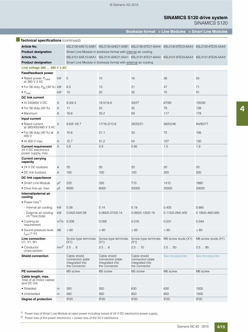
4/15Siemens NC 82 · 2015
SINAMICS S120 drive systemSINAMICS S120
Booksize format > Line Modules > Smart Line Modules
4
■ Technical specifications (continued)1) 2)
1) Power loss of Smart Line Module at rated power including losses of 24 V DC electronics power supply.2) Power loss of the power electronics + power loss of the 24 V electronics.
Article No. 6SL3130-6AE15-0AB1 6SL3130-6AE21-0AB1 6SL3130-6TE21-6AA4 6SL3130-6TE23-6AA3 6SL3130-6TE25-5AA3
Product designation Smart Line Module in booksize format with internal air cooling
Article No. 6SL3131-6AE15-0AA1 6SL3131-6AE21-0AA1 6SL3131-6TE21-6AA3 6SL3131-6TE23-6AA3 6SL3131-6TE25-5AA3
Product designation Smart Line Module in booksize format with external air cooling
Line voltage 380 … 480 V 3 AC
Feed/feedback power
• Rated power Pratedat 380 V 3 AC
kW 5 10 16 36 55
• For S6 duty PS6 (40 %) kW 6.5 13 21 47 71
• Pmax kW 10 20 35 70 91
DC link current
• At 540/600 V DC A 9.3/8.3 18.5/16.6 30/27 67/60 105/92
• For S6 duty (40 %) A 11 22 35 79 138
• Maximum A 16.6 33.2 59 117 178
Input current
• Rated currentat 380/400/480 V 3 AC
A 8.6/8.1/6.7 17/16.2/12.8 26/25/21 58/55/46 94/90/77
• For S6 duty (40 %) at 400 V
A 10.6 21.1 33 72 106
• At 400 V max. A 15.7 31.2 54 107 130
Current requirement24 V DC electronics power supply, max.
A 0.8 0.9 0.95 1.5 1.9
Current carrying capacity
• 24 V DC busbars A 20 20 20 20 20
• DC link busbars A 100 100 100 200 200
DC link capacitance
• Smart Line Module µF 220 330 710 1410 1880
• Drive line-up, max. µF 6000 6000 20000 20000 20000
Internal/external air cooling
• Power loss1)
- Internal air cooling kW 0.08 0.14 0.19 0.405 0.665
- External air cooling int.2)/ext./total
kW 0.04/0.04/0.08 0.065/0.075/0.14 0.065/0.125/0.19 0.115/0.29/0.405 0.185/0.48/0.665
• Cooling air requirement
m3/s 0.008 0.008 0.016 0.031 0.044
• Sound pressure level LpA (1 m)
dB < 60 < 60 < 60 < 60 < 60
Line connectionU1, V1, W1
Screw-type terminals (X1)
Screw-type terminals (X1)
Screw-type terminals (X1)
M6 screw studs (X1) M6 screw studs (X1)
• Conductor cross-section
mm2 2.5 … 6 2.5 … 6 2.5 … 10 2.5 … 50 2.5 … 95
Shield connection Cable shield connection plate integrated into the connector
Cable shield connection plate integrated into the connector
Cable shield connection plate integrated into the connector
See Accessories See Accessories
PE connection M5 screw M5 screw M5 screw M6 screw M6 screw
Cable length, max.Total of all motor cables and DC link
• Shielded m 350 350 630 630 1000
• Unshielded m 560 560 850 850 1500
Degree of protection IP20 IP20 IP20 IP20 IP20
© Siemens AG 2015

4/16 Siemens NC 82 · 2015
SINAMICS S120 drive systemSINAMICS S120
Booksize format > Line Modules > Smart Line Modules
4
■ Technical specifications (continued)
■ Selection and ordering data
Article No. 6SL3130-6AE15-0AB1 6SL3130-6AE21-0AB1 6SL3130-6TE21-6AA4 6SL3130-6TE23-6AA3 6SL3130-6TE25-5AA3
Product designation Smart Line Module in booksize format with internal air cooling
Article No. 6SL3131-6AE15-0AA1 6SL3131-6AE21-0AA1 6SL3131-6TE21-6AA3 6SL3131-6TE23-6AA3 6SL3131-6TE25-5AA3
Product designation Smart Line Module in booksize format with external air cooling
Line voltage 380 … 480 V 3 AC
Width mm 50 50 100 150 200
Height mm 380 380 380 380 380
Depth
- With internal air cooling
mm 270 270 270 270 270
- With external air coolingon/behind mounting surface
mm 226/66.5 226/66.5 226/66.5 226/71 226/92
Net weight
• With internal air cooling
kg 4.7 4.8 7 10.3 17
• With external air cooling
kg 5.3 5.4 8.8 13.8 18.5
Description Article No.
SINAMICS S120 Smart Line Module in booksize formatwith internal air coolingRated power:
• 5 kW 6SL3130-6AE15-0AB1
• 10 kW 6SL3130-6AE21-0AB1
• 16 kW 6SL3130-6TE21-6AA4
• 36 kW 6SL3130-6TE23-6AA3
• 55 kW 6SL3130-6TE25-5AA3
SINAMICS S120 Smart Line Module in booksize formatwith external air coolingRated power:
• 5 kW 6SL3131-6AE15-0AA1
• 10 kW 6SL3131-6AE21-0AA1
• 16 kW 6SL3131-6TE21-6AA3
• 36 kW 6SL3131-6TE23-6AA3
• 55 kW 6SL3131-6TE25-5AA3
Accessories
Shield connection plateFor Line Modules and Motor Modules in booksize format with a width of 150 mm
6SL3162-1AF00-0AA1
DC link rectifier adapterFor direct infeed of DC link voltage
• Screw-type terminals 0.5 ... 10 mm2
For Line Modules and Motor Modules in booksize format with a width of 50 mm or 100 mm
6SL3162-2BD00-0AA0
• Screw-type terminals 35 ... 95 mm2
For Line Modules and Motor Modules in booksize format with a width of 150 mm, 200 mm and 300 mm
6SL3162-2BM00-0AA0
Accessories
DC link adapter (2 units)For multi-tier configurationScrew-type terminals 35 … 95 mm2
For all Line Modules and Motor Modules in booksize format
6SL3162-2BM01-0AA0
SINAMICS S120 Terminal KitPlug-in terminals, DRIVE-CLiQ jumper, dust-proof blanking plugs for DRIVE-CLiQ port
• For Smart Line Modules with a width of 50 mm
6SL3163-8KB00-0AA1
• For Active/Smart Line Modules with a width of 100 mm
6SL3163-8FD00-0AA0
• For Active/Smart/Basic Line Modules with a width of 150 mm
6SL3163-8GF00-0AA0
Accessories for re-ordering
24 V terminal adapterFor all Line Modules and Motor Modules in booksize format
6SL3162-2AA00-0AA0
Warning labels in 30 languagesThis label set can be glued over the stan-dard German or English labels to provide warnings in other languages.One set of labels is supplied with the devices.One sign in each of the following lan-guages is provided in each set:BG, CN, CZ, DE, DK, EE, ES, FI, FR, GB, GR, HU, IE, IS, IT, JP, KR, LT, LV, MT, NL, NO, PL, PT, RO, RU, SE, SI, SK, TR
6SL3166-3AB00-0AA0
SINAMICS/SINUMERIK/SIMOTION dust-proof blanking plugsFor DRIVE-CLiQ port
• 6 units 6SL3066-4CA01-0AA0
• 50 units 6SL3066-4CA00-0AA0
Description Article No.
© Siemens AG 2015

4/17Siemens NC 82 · 2015
SINAMICS S120 drive systemSINAMICS S120
Booksize format > Line Modules > Smart Line Modules > Line reactors
4
■ Overview
Line reactor
Smart Line Modules are not warranted to operate without the specified line reactors. The use of other makes of line reactor can lead to malfunctions or irreparable damage to equipment.
■ Selection and ordering data
■ Technical specifications
Suitable forSmart Line Module
SINAMICS line reactor
Rated powerSmart Line Module
Booksize formatInternal air coolingExternal air cooling
Rated current
kW Type A Article No.
5 6SL3130-6AE15-0AB16SL3131-6AE15-0AA1
14 6SL3000-0CE15-0AA0
10 6SL3130-6AE21-0AB16SL3131-6AE21-0AA1
28 6SL3000-0CE21-0AA0
16 6SL3130-6TE21-6AA46SL3131-6TE21-6AA3
35 6SL3000-0CE21-6AA0
36 6SL3130-6TE23-6AA36SL3131-6TE23-6AA3
69 6SL3000-0CE23-6AA0
55 6SL3130-6TE25-5AA36SL3131-6TE25-5AA3
103 6SL3000-0CE25-5AA0
Article No. 6SL3000-0CE15-0AA0 6SL3000-0CE21-0AA0 6SL3000-0CE21-6AA0 6SL3000-0CE23-6AA0 6SL3000-0CE25-5AA0
Product designation Line reactor Line reactor Line reactor Line reactor Line reactor
Line voltage 380 … 480 V 3 AC
Rated current A 14 28 35 69 103
Power loss W 62 116 110 170 190
Line/load connection1U1, 1V1, 1W1/1U2, 1V2, 1W2
Screw-type terminals Screw-type terminals Screw-type terminals Screw-type terminals Screw-type terminals
• Conductor cross-section
mm2 4 10 10 16 70
PE connection Screw-type terminals Screw-type terminals M5 screw studs according to DIN 46234
M6 screw studs according to DIN 46234
M8 screw studs according to DIN 46234
• Conductor cross-section
mm2 4 10 – – –
Degree of protection IP20 IP20 IP20 IP20 IP20
Width mm 150 177 219 228 270
Height mm 175 196 180 235 275
Depth mm 70 110 144 224 290
Net weight kg 3.7 7.5 9.5 17 36
Certificate of suitability cURus cURus cURus cURus cURus
© Siemens AG 2015

4/18 Siemens NC 82 · 2015
SINAMICS S120 drive systemSINAMICS S120
Booksize format > Line Modules > Smart Line Modules > Line filters
4
■ Overview
Line filter
In plants with strict EMC requirements, line filters work together with line reactors to restrict the conducted interference emanating from the Power Modules to the limit values of Class A1 as defined in EN 55011 and Category C2 as defined in EN 61800-3. Line filters are suited only for direct connection to TN-systems.
The use of other makes of line filter can lead to malfunctions or irreparable damage to equipment.
■ Selection and ordering data
■ Technical specifications
Suitable forSmart Line Module
SINAMICS line filter
Rated powerSmart Line Module
Booksize formatInternal air coolingExternal air cooling
Rated current
kW Type A Article No.
5 6SL3130-6AE15-0AB16SL3131-6AE15-0AA1
12 6SL3000-0HE15-0AA0
10 6SL3130-6AE21-0AB16SL3131-6AE21-0AA1
25 6SL3000-0HE21-0AA0
16 6SL3130-6TE21-6AA46SL3131-6TE21-6AA3
36 6SL3000-0BE21-6DA0
36 6SL3130-6TE23-6AA36SL3131-6TE23-6AA3
74 6SL3000-0BE23-6DA1
55 6SL3130-6TE25-5AA36SL3131-6TE25-5AA3
105 6SL3000-0BE25-5DA0
Article No. 6SL3000-0HE15-0AA0 6SL3000-0HE21-0AA0 6SL3000-0BE21-6DA0 6SL3000-0BE23-6DA1 6SL3000-0BE25-5DA0
Product designation Line filter Line filter Line filter Line filter Line filter
Line voltage 380 … 480 V 3 AC
Rated current A 12 25 36 74 105
Power loss W 20 20 16 26 43
Line/load connectionL1, L2, L3/U, V, W
Screw-type terminals Screw-type terminals Screw-type terminals Screw-type terminals Screw-type terminals
• Conductor cross-section
mm2 10 10 10 35 50
PE connection M6 screw studs according to DIN 46234
M6 screw studs according to DIN 46234
M6 screw studs according to DIN 46234
M6 screw studs according to DIN 46234
M8 screw studs according to DIN 46234
Degree of protection IP20 IP20 IP20 IP20 IP20
Width mm 60 60 50 75 100
Height mm 285 285 429 433 466
Depth mm 122 122 226 226 226
Net weight kg 2.1 2.3 5.0 7.5 11.5
Certificate of suitability cURus cURus cURus cURus cURus
© Siemens AG 2015

4/19Siemens NC 82 · 2015
SINAMICS S120 drive systemSINAMICS S120
Booksize format > Line Modules > Smart Line Modules > Recommended line-side components
4
■ Overview
Suitable line-side power components are assigned depending on the power rating of the Smart Line Module.
The tables below list recommended components.
Further information about the line contactors, switch disconnectors, circuit breakers and fuses specified in the table can be found in Catalog IC 10.
Assignment of line-side power components to Smart Line Modules in booksize and booksize compact format
Suitable for Smart Line Module
Line contactor Circuit breakerIEC 60947
Circuit breakerUL489/CSA C22.2 No. 5-02
Main switch
Rated power
Booksize formatInternal air coolingExternal air cooling
Article No.
kW Type Type Type Type Article No.
5 6SL3130-6AE15-0AB16SL3131-6AE15-0AA1
3RT1023-... 3RV1031-4BA10 3VL1102-2KM30-.... 3LD2003-0TK51
10 6SL3130-6AE21-0AB16SL3131-6AE21-0AA1
3RT1026-... 3RV1031-4FA10 3VL1135-2KM30-.... 3LD2203-0TK51
16 6SL3130-6TE21-6AA46SL3131-6TE21-6AA3
3RT1035-... 3RV1031-4FA10 3VL2505-2KN30-.... 3LD2504-0TK51
36 6SL3130-6TE23-6AA36SL3131-6TE23-6AA3
3RT1045-... 3RV1041-4LA10 3VL2508-2KN30-.... 3LD2704-0TK51
55 6SL3130-6TE25-5AA36SL3131-6TE25-5AA3
3RT1054-... 3VL2712-1DC33-.... 3VL2112-2KN30-.... 3KA5330-1GE01
Suitable for Smart Line Module
Fuse switch disconnector
Switch disconnector with fuse holders
LV HRC fuse (gL/gG) UL/CSA fuse, Class JAvailable from: Mersenwww.ep.mersen.com
Rated power
Booksize formatInternal air coolingExternal air cooling
Rated current
Size Rated current
Size
kW Type Article No. Article No. A Article No. A mm Reference No.
5 6SL3130-6AE15-0AB16SL3131-6AE15-0AA1
3NP1123-1CA20 3KL5030-1GB01 16 000 3NA3805 17.5 21 × 57 AJT17-1/2
10 6SL3130-6AE21-0AB16SL3131-6AE21-0AA1
3NP1123-1CA20 3KL5030-1GB01 35 000 3NA3814 35 27 × 60 AJT35
16 6SL3130-6TE21-6AA46SL3131-6TE21-6AA3
3NP1123-1CA20 3KL5030-1GB01 35 000 3NA3814 35 27 × 60 AJT35
36 6SL3130-6TE23-6AA36SL3131-6TE23-6AA3
3NP1123-1CA20 3KL5230-1GB01 80 000 3NA3824 80 27 × 117 AJT80
55 6SL3130-6TE25-5AA36SL3131-6TE25-5AA3
3NP1143-1DA20 3KL5530-1GB01 125 000 3NA3132 125 41 × 146 AJT125
© Siemens AG 2015

4/20 Siemens NC 82 · 2015
SINAMICS S120 drive systemSINAMICS S120
Booksize format > Line Modules > Active Line Modules
4
■ Overview
Active Line Module
Active Line Modules are self-commutated feed/feedback units (with IGBTs in infeed and regenerative feedback directions) and generate a regulated DC link voltage. This means that the con-nected Motor Modules are decoupled from the line voltage. Line voltage fluctuations within the permissible supply tolerances have no effect on the motor voltage. Active Line Modules are designed for connection to grounded, star (TN, TT) and non-grounded, symmetrical IT systems.
The DC link is pre-charged via integrated pre-charging resistors.
In order to operate an Active Line Module, it is absolutely essential to use the appropriate Active Interface Module.
■ Design
The Active Line Modules in booksize format feature the following connections and interfaces as standard:• 1 power connection via screw-type terminals• 1 connection for the 24 V DC electronics power supply via the
24 V terminal adapter included in the scope of supply• 1 DC link connection via integrated DC link busbars• 3 DRIVE-CLiQ sockets• 2 PE/protective conductor connections
The status of the Active Line Modules is indicated via two multi-color LEDs.
On the 100 mm wide Active Line Module, the shield for the power supply cable can be connected to the integrated shield connec-tion plate via a shield connection terminal or tube clip, e.g. Weidmüller type KLBÜ CO 4. The shield connection terminal must not be used for strain relief. Shield connection plates are available for the 150 mm, 200 mm and 300 mm wide modules.
The signal cable shield can be connected to the Line Module by means of a shield connection terminal, e.g. Weidmüller type KLBÜ 3-8 SC.
The scope of supply of the Active Line Modules includes:• DRIVE-CLiQ cable for connection to the adjacent Control Unit
on the left for drive control, length 0.11 m• DRIVE-CLiQ cable (length depends on module width) to
connect Active Line Module to adjacent Motor Module, length = width of Active Line Module + 0.11 m
• 2 blanking plugs for sealing unused DRIVE-CLiQ sockets• Jumper for connecting the 24 V DC busbar to the adjacent
Motor Module• 24 V terminal adapter (X24)• Connector X21 for digital inputs• Fan insert for Active Line Modules of 80 kW and 120 kW
(the voltage is supplied by the Active Line Module)• 1 set of warning labels in 30 languages
■ Integration
The Active Line Module receives its control information via DRIVE-CLiQ from:• SINUMERIK 828D BASIC• SINUMERIK 828D
- Numeric Control Extensions NX10.3- Numeric Control Extensions NX15.3
© Siemens AG 2015
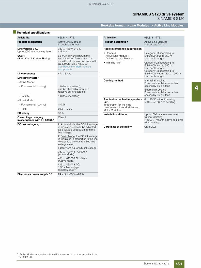
4/21Siemens NC 82 · 2015
SINAMICS S120 drive systemSINAMICS S120
Booksize format > Line Modules > Active Line Modules
4
■ Technical specifications
Article No. 6SL313 . -7TE...
Product designation Active Line Modules in booksize format
Line voltage 3 ACUp to 2000 m above sea level
380 … 480 V ±10 %-15 % < 1 min
SCCR (Short Circuit Current Rating)
65 kA in conjunction with the recommended fuses class J or circuit breakers in accordance with UL489/CSA 22.2 No. 5-02 See Recommended line-side components
Line frequency 47 … 63 Hz
Line power factor
• Active Mode
- Fundamental (cos ϕ1) 1.0 (factory setting), can be altered by input of a reactive current setpoint
- Total (λ) 1.0 (factory setting)
• Smart Mode
- Fundamental (cos ϕ1) > 0.96
- Total 0.65 … 0.90
Efficiency 98 %
Overvoltage category in accordance with EN 60664-1
Class III
DC link voltage Vd In Active Mode, the DC link voltage is regulated and can be adjusted as a voltage decoupled from the line voltage.In Smart Mode, the DC link voltage is regulated in proportion to the line voltage to the mean rectified line voltage value.Factory setting for DC link voltage:380 … 400 V 3 AC: 600 V (Active Mode)400 … 415 V 3 AC: 625 V (Active Mode)416 … 480 V 3 AC: 1.35 × line voltage (Smart Mode)1)
Electronics power supply DC 24 V DC, -15 %/+20 %
Radio interference suppression
• Standard Active Line Module + Active Interface Module
Category C3 according to EN 61800-3 up to 350 m total cable length
• With line filter Category C2 according to EN 61800-3 up to 350 m total cable lengthCategory C3 according to EN 61800-3 from 350 … 1000 m total cable length
Cooling method Internal air cooling Power units with increased air cooling by built-in fansExternal air cooling Power units with increased air cooling by built-in fans
Ambient or coolant temperature (air)In operation for line-side components, Line Modules and Motor Modules
0 … 40 °C without derating> 40 … 55 °C with derating
Installation altitude Up to 1000 m above sea level without derating,> 1000 ... 4000 m above sea level with derating
Certificate of suitability CE, cULus
Article No. 6SL313 . -7TE...
Product designation Active Line Modules in booksize format
4) Active Mode can also be selected if the connected motors are suitable for > 650 V DC.
© Siemens AG 2015
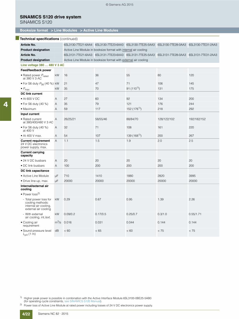
4/22 Siemens NC 82 · 2015
SINAMICS S120 drive systemSINAMICS S120
Booksize format > Line Modules > Active Line Modules
4
■ Technical specifications (continued)
Article No. 6SL3130-7TE21-6AA4 6SL3130-7TE23-6AA3 6SL3130-7TE25-5AA3 6SL3130-7TE28-0AA3 6SL3130-7TE31-2AA3
Product designation Active Line Module in booksize format with internal air cooling
Article No. 6SL3131-7TE21-6AA3 6SL3131-7TE23-6AA3 6SL3131-7TE25-5AA3 6SL3131-7TE28-0AA3 6SL3131-7TE31-2AA3
Product designation Active Line Module in booksize format with external air cooling
Line voltage 380 … 480 V 3 AC
Feed/feedback power
• Rated power Pratedat 380 V 3 AC
kW 16 36 55 80 120
• For S6 duty PS6 (40 %) kW 21 47 71 106 145
• Pmax kW 35 70 91 (1101))
1) Higher peak power is possible in combination with the Active Interface Module 6SL3100-0BE25-5AB0 (for operating cycle constraints, see SINAMICS S120 Manual).
131 175
DC link current
• At 600 V DC A 27 60 92 134 200
• For S6 duty (40 %) A 35 79 121 176 244
• Maximum A 59 117 152 (1761)) 218 292
Input current
• Rated currentat 380/400/480 V 3 AC
A 26/25/21 58/55/46 88/84/70 128/122/102 192/182/152
• For S6 duty (40 %)at 400 V
A 32 71 108 161 220
• At 400 V max. A 54 107 139 (1681)) 200 267
Current requirement24 V DC electronics power supply, max.
A 1.1 1.5 1.9 2.0 2.5
Current carrying capacity
• 24 V DC busbars A 20 20 20 20 20
• DC link busbars A 100 200 200 200 200
DC link capacitance
• Active Line Module µF 710 1410 1880 2820 3995
• Drive line-up, max. µF 20000 20000 20000 20000 20000
Internal/external air cooling
• Power loss2)
2) Power loss of Active Line Module at rated power including losses of 24 V DC electronics power supply.
- Total power loss for cooling methods: internal air cooling, external air cooling
kW 0.29 0.67 0.95 1.39 2.26
- With external air cooling, int./ext.
kW 0.09/0.2 0.17/0.5 0.25/0.7 0.3/1.0 0.55/1.71
• Cooling air requirement
m3/s 0.016 0.031 0.044 0.144 0.144
• Sound pressure levelLpA (1 m)
dB < 60 < 65 < 60 < 75 < 75
© Siemens AG 2015

4/23Siemens NC 82 · 2015
SINAMICS S120 drive systemSINAMICS S120
Booksize format > Line Modules > Active Line Modules
4
■ Technical specifications (continued).
Article No. 6SL3130-7TE21-6AA4 6SL3130-7TE23-6AA3 6SL3130-7TE25-5AA3 6SL3130-7TE28-0AA3 6SL3130-7TE31-2AA3
Product designation Active Line Module in booksize format with internal air cooling
Article No. 6SL3131-7TE21-6AA3 6SL3131-7TE23-6AA3 6SL3131-7TE25-5AA3 6SL3131-7TE28-0AA3 6SL3131-7TE31-2AA3
Product designation Active Line Module in booksize format with external air cooling
Line voltage 380 … 480 V 3 AC
Line connectionU1, V1, W1
Screw-type terminals (X1)
M6 screw studs (X1) M8 screw studs (X1) M8 screw studs (X1) M8 screw studs (X1)
• Conductor cross-section, max.
mm2 2.5 … 10 2.5 … 50 2.5 … 95, 2 × 35 2.5 … 120, 2 × 50 2.5 … 120, 2 × 50
Shield connection Integrated in the connector
See Accessories See Accessories See Accessories See Accessories
PE connection M5 screw M6 screw M6 screw M8 screw M8 screw
Cable length, max.Total of all motor cables and DC link
• Shielded m 6301)
1) Max. cable lengths in conjunction with Active Interface Module and Basic Line Filter (Category C3 in accordance with EN 61800-3).
6301) 1000 1000 1000
• Unshielded m 8501) 8501) 1500 1500 1500
Degree of protection IP20 IP20 IP20 IP20 IP20
Width mm 100 150 200 300 300
Height mm 380 380 380 380 380
• With fan2)
2) The fan is supplied with the Active Line Module and must be installed before the Active Line Module is commissioned.
mm – – – 629 629
Depth
- With internal air cooling
mm 270 270 270 270 270
- With external air cooling on/behind mounting surface
mm 226/66.5 226/71 226/92 226/82 226/82
Net weight
• With internal air cooling
kg 7 10.3 17 23 23
• With external air cooling
kg 8.8 13.8 18.5 27.7 30.7
© Siemens AG 2015

4/24 Siemens NC 82 · 2015
SINAMICS S120 drive systemSINAMICS S120
Booksize format > Line Modules > Active Line Modules
4
■ Selection and ordering data
Description Article No.
SINAMICS S120 Active Line Module in booksize formatwith internal air coolingRated power:
• 16 kW 6SL3130-7TE21-6AA4
• 36 kW 6SL3130-7TE23-6AA3
• 55 kW 6SL3130-7TE25-5AA3
• 80 kW 6SL3130-7TE28-0AA3
• 120 kW 6SL3130-7TE31-2AA3
SINAMICS S120 Active Line Module in booksize formatwith external air coolingRated power:
• 16 kW 6SL3131-7TE21-6AA3
• 36 kW 6SL3131-7TE23-6AA3
• 55 kW 6SL3131-7TE25-5AA3
• 80 kW 6SL3131-7TE28-0AA3
• 120 kW 6SL3131-7TE31-2AA3
Accessories
Shield connection plateFor Line Modules and Motor Modules in booksize format
• With a width of 150 mmfor internal air cooling
6SL3162-1AF00-0AA1
• With a width of 150 mmfor external air cooling
6SL3162-1AF00-0BA1
• With a width of 200 mmfor internal air cooling
6SL3162-1AH01-0AA0
• With a width of 200 mmfor external air cooling
6SL3162-1AH01-0BA0
• With a width of 300 mmfor all cooling types
6SL3162-1AH00-0AA0
DC link rectifier adapterFor direct infeed of DC link voltage
• Screw-type terminals 0.5 ... 10 mm2
For Line Modules and Motor Modules in booksize format with a width of 50 mm or 100 mm
6SL3162-2BD00-0AA0
• Screw-type terminals 35 ... 95 mm2
For Line Modules and Motor Modules in booksize format with a width of 150 mm, 200 mm and 300 mm
6SL3162-2BM00-0AA0
DC link adapter (2 units)For multi-tier configurationScrew-type terminals 35 … 95 mm2
For all Line Modules and Motor Modules in booksize format
6SL3162-2BM01-0AA0
SINAMICS S120 Terminal KitPlug-in terminals, DRIVE-CLiQ jumper, dust-proof blanking plugs for DRIVE-CLiQ portFor Active Line Modules
• With a width of 100 mm 6SL3163-8FD00-0AA0
• With a width of 150 mm 6SL3163-8GF00-0AA0
• With a width of 200 mm 6SL3163-8HH00-0AA0
• With a width of 300 mm 6SL3163-8JM00-0AA0
Accessories for re-ordering
24 V terminal adapterFor all Line Modules and Motor Modules in booksize format
6SL3162-2AA00-0AA0
Warning labels in 30 languagesThis label set can be glued over the standard German or English labels to provide warnings in other languages.One set of labels is supplied with the devices.One sign in each of the following lan-guages is provided in each set:BG, CN, CZ, DE, DK, EE, ES, FI, FR, GB, GR, HU, IE, IS, IT, JP, KR, LT, LV, MT, NL, NO, PL, PT, RO, RU, SE, SI, SK, TR
6SL3166-3AB00-0AA0
SINAMICS/SINUMERIK/SIMOTION dust-proof blanking plugsFor DRIVE-CLiQ port
• 6 units 6SL3066-4CA01-0AA0
• 50 units 6SL3066-4CA00-0AA0
Description Article No.
© Siemens AG 2015
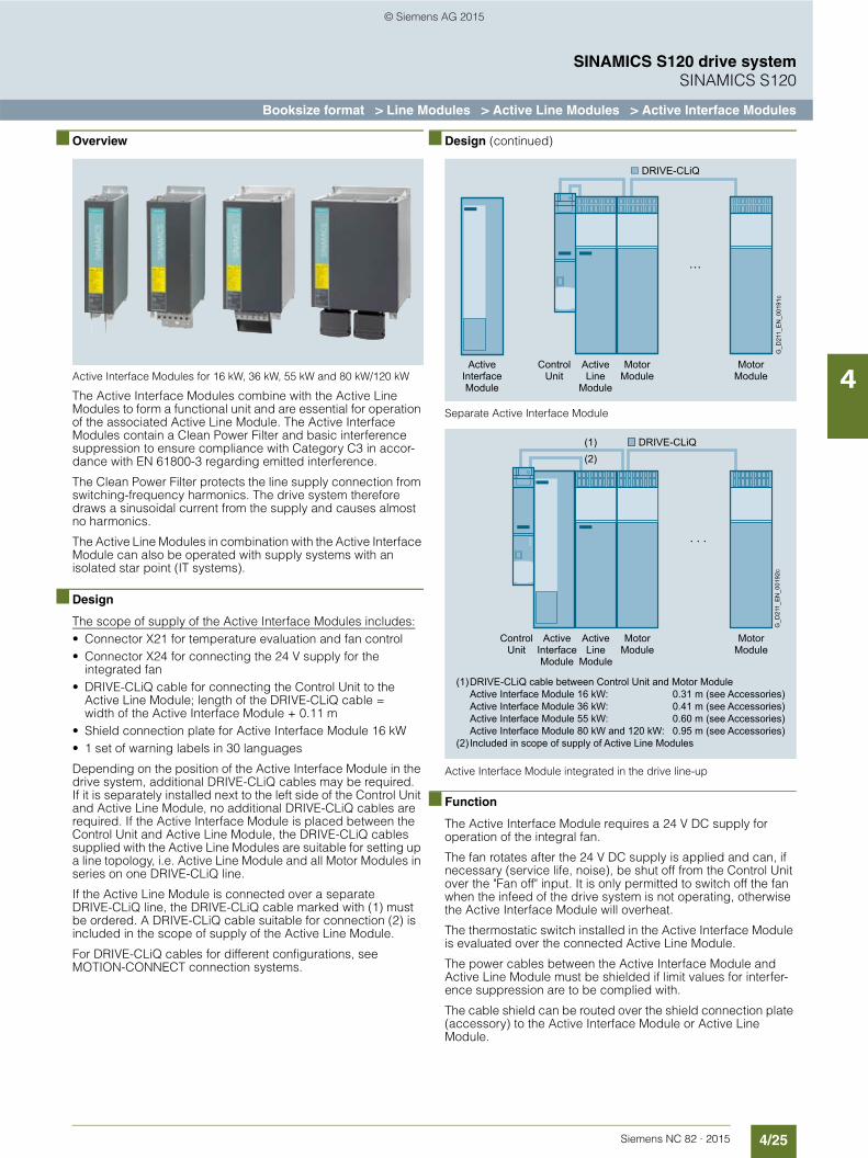
4/25Siemens NC 82 · 2015
SINAMICS S120 drive systemSINAMICS S120
Booksize format > Line Modules > Active Line Modules > Active Interface Modules
4
■ Overview
Active Interface Modules for 16 kW, 36 kW, 55 kW and 80 kW/120 kW
The Active Interface Modules combine with the Active Line Modules to form a functional unit and are essential for operation of the associated Active Line Module. The Active Interface Modules contain a Clean Power Filter and basic interference suppression to ensure compliance with Category C3 in accor-dance with EN 61800-3 regarding emitted interference.
The Clean Power Filter protects the line supply connection from switching-frequency harmonics. The drive system therefore draws a sinusoidal current from the supply and causes almost no harmonics.
The Active Line Modules in combination with the Active Interface Module can also be operated with supply systems with an isolated star point (IT systems).
■ Design
The scope of supply of the Active Interface Modules includes:• Connector X21 for temperature evaluation and fan control• Connector X24 for connecting the 24 V supply for the
integrated fan• DRIVE-CLiQ cable for connecting the Control Unit to the
Active Line Module; length of the DRIVE-CLiQ cable = width of the Active Interface Module + 0.11 m
• Shield connection plate for Active Interface Module 16 kW• 1 set of warning labels in 30 languages
Depending on the position of the Active Interface Module in the drive system, additional DRIVE-CLiQ cables may be required. If it is separately installed next to the left side of the Control Unit and Active Line Module, no additional DRIVE-CLiQ cables are required. If the Active Interface Module is placed between the Control Unit and Active Line Module, the DRIVE-CLiQ cables supplied with the Active Line Modules are suitable for setting up a line topology, i.e. Active Line Module and all Motor Modules in series on one DRIVE-CLiQ line.
If the Active Line Module is connected over a separate DRIVE-CLiQ line, the DRIVE-CLiQ cable marked with (1) must be ordered. A DRIVE-CLiQ cable suitable for connection (2) is included in the scope of supply of the Active Line Module.
For DRIVE-CLiQ cables for different configurations, see MOTION-CONNECT connection systems.
■ Design (continued)
Separate Active Interface Module
Active Interface Module integrated in the drive line-up
■ Function
The Active Interface Module requires a 24 V DC supply for operation of the integral fan.
The fan rotates after the 24 V DC supply is applied and can, if necessary (service life, noise), be shut off from the Control Unit over the "Fan off" input. It is only permitted to switch off the fan when the infeed of the drive system is not operating, otherwise the Active Interface Module will overheat.
The thermostatic switch installed in the Active Interface Module is evaluated over the connected Active Line Module.
The power cables between the Active Interface Module and Active Line Module must be shielded if limit values for interfer-ence suppression are to be complied with.
The cable shield can be routed over the shield connection plate (accessory) to the Active Interface Module or Active Line Module.
G_D
211_
EN
_001
91c
Motor Module
Motor Module
ActiveInterfaceModule
ActiveLine
Module
ControlUnit
DRIVE-CLiQ
. . .
DRIVE-CLiQ cable between Control Unit and Motor ModuleActive Interface Module 16 kW: 0.31 m (see Accessories)Active Interface Module 36 kW: 0.41 m (see Accessories)Active Interface Module 55 kW: 0.60 m (see Accessories)Active Interface Module 80 kW and 120 kW: 0.95 m (see Accessories)Included in scope of supply of Active Line Modules
(1)
(2)
G_D
211_
EN
_001
92c
Motor Module
Motor Module
ActiveInterfaceModule
ActiveLine
Module
ControlUnit
DRIVE-CLiQ
. . .
(1)(2)
© Siemens AG 2015
4/26 Siemens NC 82 · 2015
SINAMICS S120 drive systemSINAMICS S120
Booksize format > Line Modules > Active Line Modules > Active Interface Modules
4
■ Technical specifications
■ Selection and ordering data
Article No. 6SL3100-0BE21-6AB0 6SL3100-0BE23-6AB0 6SL3100-0BE25-5AB0 6SL3100-0BE28-0AB0 6SL3100-0BE31-2AB0
Product designation Active Interface Module with internal air cooling
Line voltage 380 … 480 V 3 AC
Rated current A 27 60 88 132 200
Current requirement24 V DC electronics power supply, max.
A 0.25 0.5 0.6 1.2 1.2
Internal resistanceDigital input"Fan off" (X21/Pin 4)
Ω 1440 ±10 % 1440 ±10 % 1440 ±10 % 1440 ±10 % 1440 ±10 %
Power loss kW 0.3 0.39 0.45 0.575 0.8
Cooling air requirement
m3/s 0.03 0.04 0.075 0.15 0.15
Sound pressure level LpA (1 m)
dB 57 60 66 68 68
Line/load connectionL1, L2, L3/U2, V2, W2
Screw-type terminals
Screw-type terminals
M8 screw studs M8 screw studs M8 screw studs
• Conductor cross-section
mm2 16 50 2.5 … 95 or 2 × 35
2.5 … 120 or 2 × 50
2.5 … 120 or 2 × 50
Thermostatic switch NC contact NC contact NC contact NC contact NC contact
• Switching capacity AC 250 V/1.6 A 250 V/1.6 A 250 V/1.6 A 250 V/1.6 A 250 V/1.6 A
• Switching capacity DC 60 V/0.75 A 60 V/0.75 A 60 V/0.75 A 60 V/0.75 A 60 V/0.75 A
PE connection M5 screw M5 screw M6 screw M8 screw M8 screw
Degree of protection IP20 IP20 IP20 IP20 IP20
Width × Height × Depth mm 100 × 380 × 270 150 × 380 × 270 200 × 380 × 270 300 × 380 × 270 300 × 380 × 270
Net weight kg 11 18.5 21 29 36
Certificate of suitability cURus cURus cURus cURus cURus
Suitable forActive Line Module
SINAMICS Active Interface Module
Rated powerActive Line Module
Booksize formatInternal air coolingExternal air cooling
Rated current
kW Type A Article No.
16 6SL3130-7TE21-6AA46SL3131-7TE21-6AA3
27 6SL3100-0BE21-6AB0
36 6SL3130-7TE23-6AA36SL3131-7TE23-6AA3
60 6SL3100-0BE23-6AB0
55 6SL3130-7TE25-5AA36SL3131-7TE25-5AA3
88 6SL3100-0BE25-5AB0
80 6SL3130-7TE28-0AA36SL3131-7TE28-0AA3
132 6SL3100-0BE28-0AB0
120 6SL3130-7TE31-2AA36SL3131-7TE31-2AA3
200 6SL3100-0BE31-2AB0
Description Article No.
Accessories
Shield connection plateFor Active Interface Module
• 16 kW Included in scope of supply
• 36 kW 6SL3163-1AF00-0AA0
• 55 kW 6SL3163-1AH00-0AA0
• 80 kW and 120 kW 6SL3163-1AM00-0AA0
Accessories (continued)
DRIVE-CLiQ cable, pre-assembledDegree of protection of connector IP20/IP20For Active Interface Module
• 16 kW, length 0.31 m 6SL3060-4AK00-0AA0
• 36 kW, length 0.41 m 6SL3060-4AP00-0AA0
• 55 kW, length 0.60 m 6SL3060-4AU00-0AA0
• 80 kW and 120 kW, length 0.95 m 6SL3060-4AA10-0AA0
SINAMICS S120 Terminal KitPlug-in terminals, DRIVE-CLiQ jumperFor Active Interface Modules
• With a width of 100 mm 6SL3160-8CD10-0AA0
• With a width of 150 mm 6SL3160-8DF10-0AA0
• With a width of 200 mm 6SL3160-8EH10-0AA0
• With a width of 300 mm 6SL3160-8FM10-0AA0
Accessories for re-ordering
Warning labels in 30 languagesThis label set can be glued over the standard German or English labels to provide warnings in other languages.One set of labels is supplied with the devices.One sign in each of the following languages is provided in each set: BG, CN, CZ, DE, DK, EE, ES, FI, FR, GB, GR, HU, IE, IS, IT, JP, KR, LT, LV, MT, NL, NO, PL, PT, RO, RU, SE, SI, SK, TR
6SL3166-3AB00-0AA0
Description Article No.
© Siemens AG 2015

4/27Siemens NC 82 · 2015
SINAMICS S120 drive systemSINAMICS S120
Booksize format > Line Modules > Active Line Modules > Basic Line Filters
4
■ Overview
Basic Line Filter
Basic Line Filters are used on machines on which conducted interference emissions in the frequency range between 150 kHz and 30 MHz need to be damped in accordance with the requirements of CE-EMC legislation.
With the Basic Line Filters in combination with the Active Inter-face Modules, the limits for the interference voltages can be ex-tended to Category C2 (IEC 61800-3) or, retaining Category C3, longer total cable lengths are possible for the configuration.
■ Selection and ordering data
■ Technical specifications
Suitable forActive Line Module
SINAMICS Basic Line Filter
Rated powerActive Line Module
Booksize formatInternal air coolingExternal air cooling
Rated current
kW Type A Article No.
16 6SL3130-7TE21-6AA46SL3131-7TE21-6AA3
36 6SL3000-0BE21-6DA0
36 6SL3130-7TE23-6AA36SL3131-7TE23-6AA3
74 6SL3000-0BE23-6DA1
55 6SL3130-7TE25-5AA36SL3131-7TE25-5AA3
105 6SL3000-0BE25-5DA0
80 6SL3130-7TE28-0AA36SL3131-7TE28-0AA3
132 6SL3000-0BE28-0DA0
120 6SL3130-7TE31-2AA36SL3131-7TE31-2AA3
192 6SL3000-0BE31-2DA0
Article No. 6SL3000-0BE21-6DA0 6SL3000-0BE23-6DA1 6SL3000-0BE25-5DA0 6SL3000-0BE28-0DA0 6SL3000-0BE31-2DA0
Product designation Basic Line Filter Basic Line Filter Basic Line Filter Basic Line Filter Basic Line Filter
Line voltage 380 … 480 V 3 AC
Rated current A 36 74 105 132 192
Power loss W 16 28 41 48 86
Line/load connectionL1, L2, L3 / U, V, W
Screw-type terminals Screw-type terminals Screw-type terminals Screw-type terminals Screw-type terminals
• Conductor cross-section
mm2 10 35 50 95 95
PE connection M6 screw studs according to DIN 46234
M6 screw studs according to DIN 46234
M8 screw studs according to DIN 46234
M10 screw studs according to DIN 46234
M10 screw studs according to DIN 46234
Degree of protection IP20 IP20 IP20 IP20 IP20
Width mm 50 75 100 150 150
Height mm 429 433 466 479 479
Depth mm 226 226 226 226 226
Net weight kg 5 7.5 11.5 18.2 18.8
Certificate of suitability cURus cURus cURus cURus cURus
© Siemens AG 2015

4/28 Siemens NC 82 · 2015
SINAMICS S120 drive systemSINAMICS S120
Booksize format > Line Modules > Active Line Modules > Recommended line-side components
4
■ Overview1)
Suitable line-side power components are assigned depending on the power rating of the Active Line Modules.
The tables below list recommended components.
Further information about the line contactors, switch disconnectors, circuit breakers and fuses specified in the table can be found in Catalog IC 10.
Assignment of line-side power components to Active Line Modules in booksize format
1) Not suitable for 3NP and 3KL switch disconnectors.
Suitable for Active Line Module
Line contactor Output coupling device for line contactor
Main switch Leading auxiliary switch for main switch
Rated power
Booksize formatInternal air coolingExternal air cooling
kW Type Type Article No. Article No. Article No.
16 6SL3130-7TE21-6AA46SL3131-7TE21-6AA3
3RT1035-… 3TX7004-1LB00 3LD2504-0TK51 3LD9200-5B
36 6SL3130-7TE23-6AA36SL3131-7TE23-6AA3
3RT1045-… 3TX7004-1LB00 3LD2704-0TK51 3LD9200-5B
55 6SL3130-7TE25-5AA36SL3131-7TE25-5AA3
3RT1054-… 3TX7004-1LB00 3KA5330-1GE01 3KX3552-3EA01
80 6SL3130-7TE28-0AA36SL3131-7TE28-0AA3
3RT1056-… 3TX7004-1LB00 3KA5330-1GE01 3KX3552-3EA01
120 6SL3130-7TE31-2AA36SL3131-7TE31-2AA3
3RT1065-… 3TX7004-1LB00 3KA5730-1GE01 3KX3552-3EA01
Suitable for Active Line Module
Circuit breakerIEC 60947
Circuit breakerUL489/CSA C22.2 No. 5-02
Fuse switch disconnector
Switch disconnector with fuse holders
Leading auxiliary switch for switch disconnector with fuse holdersRated
powerBooksize format
Article No.
kW Type Type Type Article No. Article No. Article No.
16 6SL3130-7TE21-6AA46SL3131-7TE21-6AA3
3RV1031-4FA10 3VL2505-2KN30-.... 3NP1123-1CA20 3KL5230-1GB01 3KX3552-3EA01
36 6SL3130-7TE23-6AA36SL3131-7TE23-6AA3
3RV1041-4LA10 3VL2508-2KN30-.... 3NP1123-1CA20 3KL5230-1GB01 3KX3552-3EA01
55 6SL3130-7TE25-5AA36SL3131-7TE25-5AA3
3VL2712-1DC33-.... 3VL2512-2KN30-.... 3NP1143-1DA20 3KL5530-1GB01 3KX3552-3EA01
80 6SL3130-7TE28-0AA36SL3131-7TE28-0AA3
3VL3720-1DC33-.... 3VL3517-2KN30-.... 3NP1143-1DA20 3KL5530-1GB01 3KX3552-3EA01
120 6SL3130-7TE31-2AA36SL3131-7TE31-2AA3
3VL3725-1DC36-.... 3VL3525-2KN30-.... 3NP1153-1DA20 3KL5730-1GB01 3KX3552-3EA01
Suitable for Active Line Module
NEOZED fuse(gL/gG)
DIAZED fuse(gL/gG)
LV HRC fuse(gL/gG)
UL/CSA fuse, Class J1)
Available from: Mersen www.ep.mersen.com
Rated power
Booksize format
Rated current
Size Rated current
Size Rated current
Size Rated current
Size
kW Type Article No. Article No. Article No. mm Ref. No.
16 6SL3130-7TE21-6AA46SL3131-7TE21-6AA3
35 D02 5SE2335 35 DIII 5SB411 35 000 3NA3814 35 27×60 AJT35
36 6SL3130-7TE23-6AA36SL3131-7TE23-6AA3
– – – 80 DIV 5SC211 80 000 3NA3824 80 29×117 AJT80
55 6SL3130-7TE25-5AA36SL3131-7TE25-5AA3
– – – – – – 125 1 3NA3132 125 41×146 AJT125
80 6SL3130-7TE28-0AA36SL3131-7TE28-0AA3
– – – – – – 160 1 3NA3136 175 41×146 AJT175
120 6SL3130-7TE31-2AA36SL3131-7TE31-2AA3
– – – – – – 250 1 3NA3144 250 54×181 AJT250
© Siemens AG 2015
4/29Siemens NC 82 · 2015
SINAMICS S120 drive systemSINAMICS S120
Booksize format > Line Modules > Basic Line Modules
4
■ Overview
20 kW, 40 kW and 100 kW Basic Line Modules in booksize format
Basic Line Modules are used for applications in which no energy is returned to the supply or where the energy exchange between motor and generator axes takes place in the DC link. Basic Line Modules can only feed energy from the supply system into the DC link, energy cannot be fed back into the supply system. The DC link voltage is directly derived from the 3-phase line voltage via a 6-pulse bridge circuit. Basic Line Modules are designed for connection to grounded, star TN, TT systems and non-grounded, symmetrical IT systems. The connected Motor Modules are pre-charged over the integrated pre-charging resistors (20 kW and 40 kW) or through activation of the thyristors (100 kW).
The 20 kW and 40 kW Basic Line Modules are equipped with an integrated brake chopper and can be directly used for applica-tions in generating mode after connecting an external braking resistor.A Braking Module is only required with a 100 kW Basic Line Module in generating mode.
■ Design
The Basic Line Modules in booksize format feature the following connections and interfaces as standard:• 1 power connection• 1 connection for the 24 V DC electronics power supply• 1 DC link connection• 3 DRIVE-CLiQ sockets• 1 connection for braking resistor
(20 kW and 40 kW Basic Line Modules only)• 1 temperature sensor input
(KTY84-130 or PTC/Pt100)
The status of the Basic Line Modules is indicated via two multi-color LEDs.
The scope of supply of the Basic Line Modules includes:• DRIVE-CLiQ cable for connection to the adjacent Control Unit
on the left for drive control, length 0.11 m• DRIVE-CLiQ cable (length depends on module width) to
connect Basic Line Module to adjacent Motor Module, length = width of Basic Line Module + 0.11 m
• Jumper for connecting the 24 V DC busbar to the adjacent Motor Module
• 24 V terminal adapter (X24)• Connector X21• 2 blanking plugs for sealing unused DRIVE-CLiQ sockets• 1 set of warning labels in 30 languages
Note:
The thermostatic switch built into the braking resistor must be looped into the shutdown chain of the drive to prevent thermal overloading of the system in the event of a fault. If a braking re-sistor is not connected, a jumper must be connected between X21.1 and X21.2.
■ Integration
The Basic Line Module receives its control information via DRIVE-CLiQ from:• SINUMERIK 828D BASIC• SINUMERIK 828D
- Numeric Control Extensions NX10.3- Numeric Control Extensions NX15.3
© Siemens AG 2015

4/30 Siemens NC 82 · 2015
SINAMICS S120 drive systemSINAMICS S120
Booksize format > Line Modules > Basic Line Modules
4
■ Technical specifications1) 2)
1) Can also be operated on supply systems with 200 ... 240 V 3 AC ±10 % with appropriate parameter assignment and reduced output.2) The DC link voltage is unregulated and load-dependent.
Article No. 6SL313 . -1TE...
Product designation Basic Line Modules in booksize format
Line voltageUp to 2000 m above sea level
380 … 480 V 3 AC ±10 %-15 % < 1 min1)
SCCR (Short Circuit Current Rating)
65 kA in conjunction with the recommended fuses class J or circuit breakers in accordance with UL489/CSA 22.2 No. 5-02 See Recommended line-side components
Line frequency 47 … 63 Hz
Line power factorAt rated power
• Fundamental (cos ϕ1) > 0.96
• Total (λ) 0.75 … 0.93
Overvoltage category in accordance with EN 60664-1
Class III
DC link voltage, approx. 1.35 × line voltage2)
Electronics power supply DC 24 V -15 %/+20 %
Radio interference suppression
• Standard
- 20 kW and 40 kW Basic Line Modules No radio interference suppression
- 100 kW Basic Line Module Category C3 according to EN 61800-3up to 350 m total cable length (shielded)
• With line filter Category C2 according to EN 61800-3up to 350 m total cable length (shielded)
Cooling method Internal air cooling Power units with increased air cooling by built-in fans
Ambient or coolant temperature (air)In operation for line-side components, Line Modules and Motor Modules
0 … 40 °C without derating> 40 … 55 °C with derating
Installation altitude Up to 1000 m above sea level without derating, > 1000 ... 4000 m above sea level with derating
Certificate of suitability CE, cULus
Article No. 6SL313 . -1TE...
Product designation Basic Line Modules in booksize format
Article No. 6SL3130-1TE22-0AA0 6SL3130-1TE24-0AA0 6SL3130-1TE31-0AA0
Product designation Basic Line Module in booksize format with internal air coolingwith varnished modules
Basic Line Module in booksize format with internal air coolingwith varnished modules
Basic Line Module in booksize format with internal air coolingwith varnished modules
Line voltage 380 … 480 V 3 AC
Power
• Rated power Pratedat 380 V 3 AC
kW 20 40 100
• For S6 duty PS6 (40 %) kW 26 52 130
• Pmax kW 60 120 175
Braking powerWith external braking resistor
• PBmax. (= 2 × Prated) kW 40 80 –
• Continuous braking power Pd (= 0.25 × Prated)
kW 5 10 –
DC link current
• At 600 V DC A 34 67 167
• For S6 duty (40 %) A 43 87 217
• Maximum A 100 200 292
Input current
• Rated currentat 380 V 3 AC
A 35 69 172
• Maximum A 113 208 301
Activation thresholdBraking chopper
V 774 774 –
© Siemens AG 2015

4/31Siemens NC 82 · 2015
SINAMICS S120 drive systemSINAMICS S120
Booksize format > Line Modules > Basic Line Modules
4
■ Technical specifications (continued)1)
1) Power loss of Basic Line Module at rated power including losses of 24 V DC electronics power supply.
Article No. 6SL3130-1TE22-0AA0 6SL3130-1TE24-0AA0 6SL3130-1TE31-0AA0
Product designation Basic Line Module in booksize format with internal air coolingwith varnished modules
Line voltage 380 … 480 V 3 AC
Resistance valueExternal braking resistor
Ω ≥ 14.8 ≥ 7.4 –
Cable lengthTo braking resistor, max.
m 15 15 –
Connection for braking resistor (X2)
Screw-type terminals Screw-type terminals –
• Conductor cross-section, max. mm2 0.5 … 4 0.5 … 10
Current requirement24 V DC electronics power supply, max.
A 1 1.4 2
Current carrying capacity
• 24 V DC busbars A 20 20 20
• DC link busbars A 100 200 200
DC link capacitance
• Basic Line Module µF 940 1880 4100
• Drive line-up, max. µF 20000 20000 50000
Internal air cooling
• Power loss1) kW 0.144 0.284 0.628
• Cooling air requirement m3/s 0.016 0.031 0.05
• Sound pressure level LpA (1 m)
dB < 60 < 65 < 65
Line connectionU1, V1, W1
Screw-type terminals Screw-type terminals M8 screw studs
• Conductor cross-section, max. mm2 0.5 … 16 10 … 50 1 × 35 … 120 or2 × 50
Shield connection Integrated into the power plug See Accessories See Accessories
PE connection M5 screw M6 screw M6 screw
Cable length, max.(Total of all motor power cables and DC link)
• Shielded m 630 630 1000
• Unshielded m 850 850 1500
Degree of protection IP20 IP20 IP20
Width mm 100 150 200
Height mm 380 380 380
Depth mm 270 270 270
Net weight kg 6.8 11.3 15.8
© Siemens AG 2015
4/32 Siemens NC 82 · 2015
SINAMICS S120 drive systemSINAMICS S120
Booksize format > Line Modules > Basic Line Modules
4
■ Selection and ordering data
Description Article No.
SINAMICS S120 Basic Line Module in booksize format with internal air coolingRated power:
• 20 kW 6SL3130-1TE22-0AA0
• 40 kW 6SL3130-1TE24-0AA0
• 100 kW 6SL3130-1TE31-0AA0
Accessories
Shield connection plateFor Line Modules and Motor Modules in booksize format
• With a width of 150 mm for internal air cooling
6SL3162-1AF00-0AA1
• With a width of 200 mm for internal air cooling
6SL3162-1AH01-0AA0
DC link rectifier adapterFor direct infeed of DC link voltage
• Screw-type terminals 0.5 ... 10 mm2
For Line Modules and Motor Modules in booksize format with a width of 50 mm or 100 mm
6SL3162-2BD00-0AA0
• Screw-type terminals 35 ... 95 mm2
For Line Modules and Motor Modules in booksize format with a width of 150 mm, 200 mm and 300 mm
6SL3162-2BM00-0AA0
DC link adapter (2 units)For multi-tier configurationScrew-type terminals 35 … 95 mm2
For all Line Modules and Motor Modules in booksize format
6SL3162-2BM01-0AA0
SINAMICS S120 Terminal KitPlug-in terminals, DRIVE-CLiQ jumper, dust-proof blanking plugs for DRIVE-CLiQ port
• For Basic Line Modules with a width of 100 mm
6SL3163-8LD00-0AA0
Accessories for re-ordering
24 V terminal adapterFor all Line Modules and Motor Modules in booksize format
6SL3162-2AA00-0AA0
Warning labels in 30 languagesThis label set can be glued over the standard German or English labels to provide warnings in other languages.One set of labels is supplied with the devices.One sign in each of the following languages is provided in each set:BG, CN, CZ, DE, DK, EE, ES, FI, FR, GB, GR, HU, IE, IS, IT, JP, KR, LT, LV, MT, NL, NO, PL, PT, RO, RU, SE, SI, SK, TR
6SL3166-3AB00-0AA0
SINAMICS/SINUMERIK/SIMOTION dust-proof blanking plugsFor DRIVE-CLiQ port
• 6 units 6SL3066-4CA01-0AA0
• 50 units 6SL3066-4CA00-0AA0
Description Article No.
© Siemens AG 2015

4/33Siemens NC 82 · 2015
SINAMICS S120 drive systemSINAMICS S120
Booksize format > Line Modules > Basic Line Modules > Line reactors
4
■ Overview
20 kW and 100 kW line reactors
Line reactors limit low-frequency line harmonic effects and re-duce the load on the semiconductors of the Basic Line Module.
The use of other makes of line reactor can lead to malfunctions or irreparable damage to equipment.
■ Selection and ordering data
■ Technical specifications
Suitable forBasic Line Module
SINAMICS line reactor
Rated powerBasic Line Module
Booksize format Rated current
kW Type A Article No.
20 6SL3130-1TE22-0AA0 37 6SL3000-0CE22-0AA0
40 6SL3130-1TE24-0AA0 74 6SL3000-0CE24-0AA0
100 6SL3130-1TE31-0AA0 185 6SL3000-0CE31-0AA0
Article No. 6SL3000-0CE22-0AA0 6SL3000-0CE24-0AA0 6SL3000-0CE31-0AA0
Product designation Line reactor Line reactor Line reactor
Line voltage 380 … 480 V 3 AC
Rated current A 37 74 185
Power loss
• At 50 Hz W 130 270 480
• At 60 Hz W 154 320 565
Line/load connection Screw-type terminals Screw-type terminals Flat connector for M8 screw
• Conductor cross-section mm2 0.5 … 16 2.5 … 35 –
Degree of protection IP20 IP20 IP00
Width mm 178 210 261
Height mm 165 245 228
Depth mm 100 93 137
Net weight kg 5.2 11.2 21.7
Certificate of suitability cURus cURus cURus
© Siemens AG 2015
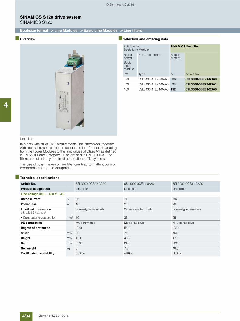
4/34 Siemens NC 82 · 2015
SINAMICS S120 drive systemSINAMICS S120
Booksize format > Line Modules > Basic Line Modules > Line filters
4
■ Overview
Line filter
In plants with strict EMC requirements, line filters work together with line reactors to restrict the conducted interference emanating from the Power Modules to the limit values of Class A1 as defined in EN 55011 and Category C2 as defined in EN 61800-3. Line filters are suited only for direct connection to TN systems.
The use of other makes of line filter can lead to malfunctions or irreparable damage to equipment.
■ Selection and ordering data
■ Technical specifications
Suitable forBasic Line Module
SINAMICS line filter
Rated powerBasic Line Module
Booksize format Rated current
kW Type A Article No.
20 6SL3130-1TE22-0AA0 36 6SL3000-0BE21-6DA0
40 6SL3130-1TE24-0AA0 74 6SL3000-0BE23-6DA1
100 6SL3130-1TE31-0AA0 192 6SL3000-0BE31-2DA0
Article No. 6SL3000-0CE22-0AA0 6SL3000-0CE24-0AA0 6SL3000-0CE31-0AA0
Product designation Line filter Line filter Line filter
Line voltage 380 … 480 V 3 AC
Rated current A 36 74 192
Power loss W 16 20 90
Line/load connectionL1, L2, L3 / U, V, W
Screw-type terminals Screw-type terminals Screw-type terminals
• Conductor cross-section mm2 10 35 95
PE connection M6 screw stud M6 screw stud M10 screw stud
Degree of protection IP20 IP20 IP20
Width mm 50 75 150
Height mm 429 433 479
Depth mm 226 226 226
Net weight kg 5 7.5 18.8
Certificate of suitability cURus cURus cURus
© Siemens AG 2015

4/35Siemens NC 82 · 2015
SINAMICS S120 drive systemSINAMICS S120
Booksize format > Line Modules > Basic Line Modules > Recommended line-side components
4
■ Overview1)
Suitable line-side power components are assigned depending on the power rating of the Basic Line Modules.
The tables below list recommended components.
Further information about the line contactors, switch disconnectors, circuit breakers and fuses specified in the table can be found in Catalog IC 10.
Assignment of line-side power components to Basic Line Modules in booksize format
1) Not suitable for 3NP and 3KL switch disconnectors.
Suitable for Basic Line Module
Line contactor Output coupling device for line contactor
Main switch
Rated power
Booksize format
kW Type Type Article No. Article No.
20 6SL3130-1TE22-0AA0 3RT1035-… 3TX7004-1LB00 3LD2504-0TK51
40 6SL3130-1TE24-0AA0 3RT1045-… 3TX7004-1LB00 3LD2704-0TK51
100 6SL3130-1TE31-0AA0 3RT1056-… 3TX7004-1LB00 3KA5530-1GE01
Suitable for Basic Line Module
Circuit breakerIEC 60947
Circuit breakerUL489/CSA C22.2 No. 5-02
Fuse switch disconnector
Rated power
Booksize format
Article No.
kW Type Type Type Article No.
20 6SL3130-1TE22-0AA0 3RV1041-4JA10 3VL2506-2KN30-.... 3NP1123-1CA20
40 6SL3130-1TE24-0AA0 3VL2710-1DC33-.... 3VL2510-2KN30-.... 3NP1123-1CA20
100 6SL3130-1TE31-0AA0 3VL3725-1DC36-.... 3VL3525-2KN30-.... 3NP1123-1DA20
Suitable for Basic Line Module
Switch disconnector with fuse holders
LV HRC fuse(gL/gG)
UL/CSA fuse, Class J1)
Available from: Mersen www.ep.mersen.com
Rated power
Booksize format Rated current
Size Rated current
Size
kW Type Article No. A Article No. A mm Reference No.
20 6SL3130-1TE22-0AA0 3KL5230-1GB01 63 000 3NA3822 60 27 × 60 AJT60
40 6SL3130-1TE24-0AA0 3KL5230-1GB01 100 000 3NA3830 100 27 × 117 AJT100
100 6SL3130-1TE31-0AA0 3KL5730-1GB01 250 1 3NA3144 250 54 × 181 AJT250
© Siemens AG 2015

4/36 Siemens NC 82 · 2015
SINAMICS S120 drive systemSINAMICS S120
Booksize format > Motor Modules > Single Motor Modules
4
■ Design
Single Motor Module in booksize format
The Single Motor Modules in booksize format feature the following connections and interfaces as standard:• 2 DC link connections via integrated DC link busbars• 1 electronics power supply connection via integrated
24 V DC bars• 3 DRIVE-CLiQ sockets• 1 motor connection, plug-in (not included in scope of supply)
or screw-stud depending on rated output current• 1 safe standstill input (Enable Pulses)• 1 safe motor brake control• 1 temperature sensor input (KTY84-130 or PTC)• 2 PE/protective conductor connections
The status of the Motor Modules is indicated via two multi-color LEDs.
The motor cable shield is inside the connector on 50 mm and 100 mm wide Motor Modules. A shield connection plate can be supplied for 150 mm, 200 mm and 300 mm wide Motor Modules. On these modules, the motor cable shield can be connected using a tube clip.
The signal cable shield can be connected to the Motor Module by means of a shield terminal, e.g. Weidmüller type KLBÜ 3-8 SC
■ Design (continued)
The scope of supply of the Motor Modules includes:• DRIVE-CLiQ cable appropriate to the width of the Motor
Module for connection to the adjacent Motor Module, length = width of Motor Module + 0.06 m
• Jumper for connecting the 24 V DC busbar to the adjacent Motor Module
• Connector X21• Connector X11 for the motor brake connection (for Motor
Modules with a rated output current of 45 A to 200 A)• 2 blanking plugs for sealing unused DRIVE-CLiQ sockets• Fan insert for the 132 A and 200 A Motor Modules
(the voltage for the fan insert is supplied by the Motor Module)• 1 set of warning labels in 30 languages
■ Integration
The Single Motor Module receives its control information via DRIVE-CLiQ from:• SINUMERIK 828D BASIC• SINUMERIK 828D
- Numeric Control Extensions NX10.3- Numeric Control Extensions NX15.3
■ Technical specifications
Article No. 6SL312 . -1TE...
Product designation Single Motor Module in booksize format
DC link voltage DCUp to 2000 m above sea level
510 … 720 V(line voltage 380 … 480 V 3 AC)
Output frequency 0 … 650 Hz1)2)
Electronics power supply DC 24 V -15 %/+20 %
Cooling method Internal air cooling,External air coolingPower units with increased air cooling by built-in fans
Ambient or coolant temperature (air)In operation for line-side compo-nents, Line Modules and Motor Modules
0 … 40 °C without derating> 40 … 55 °C with derating
Installation altitude Up to 1000 m above sea level without derating, > 1000 ... 4000 m above sea level with derating
Certificate of suitability CE, cULus
Safety Integrated Safety Integrity Level 2 (SIL 2) according to IEC 61508,Performance Level d (PLd) according to ISO 13849-1 andControl category 3 according to ISO 13849-1/EN 954-1
1) At rated output current (max. output frequency 1300 Hz for 62.5 µs current control cycle, 8 kHz pulse frequency, 60 % permissible output current). Note the correlation between max. output frequency, pulse frequency and current derating.
2) The output frequency is currently limited to 550 Hz. The specified values apply to systems with license for high output frequency.
© Siemens AG 2015
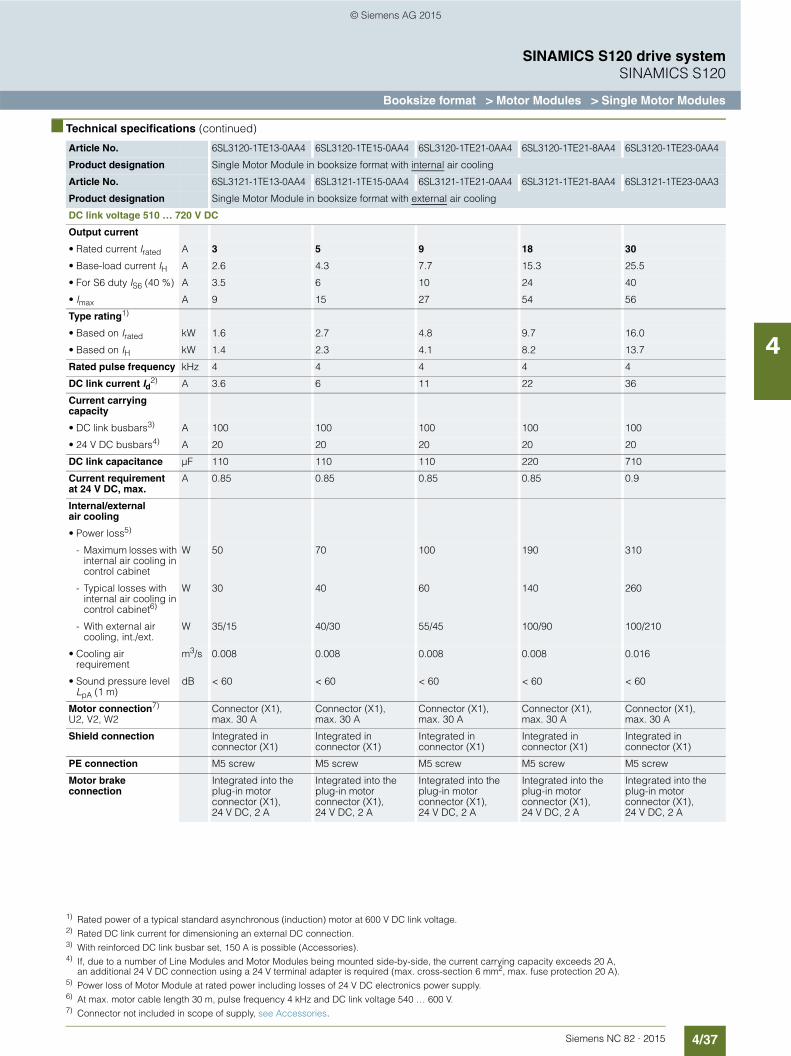
4/37Siemens NC 82 · 2015
SINAMICS S120 drive systemSINAMICS S120
Booksize format > Motor Modules > Single Motor Modules
4
■ Technical specifications (continued)
Article No. 6SL3120-1TE13-0AA4 6SL3120-1TE15-0AA4 6SL3120-1TE21-0AA4 6SL3120-1TE21-8AA4 6SL3120-1TE23-0AA4
Product designation Single Motor Module in booksize format with internal air cooling
Article No. 6SL3121-1TE13-0AA4 6SL3121-1TE15-0AA4 6SL3121-1TE21-0AA4 6SL3121-1TE21-8AA4 6SL3121-1TE23-0AA3
Product designation Single Motor Module in booksize format with external air cooling
DC link voltage 510 … 720 V DC
Output current
• Rated current Irated A 3 5 9 18 30
• Base-load current IH A 2.6 4.3 7.7 15.3 25.5
• For S6 duty IS6 (40 %) A 3.5 6 10 24 40
• Imax A 9 15 27 54 56
Type rating1)
• Based on Irated kW 1.6 2.7 4.8 9.7 16.0
• Based on IH kW 1.4 2.3 4.1 8.2 13.7
Rated pulse frequency kHz 4 4 4 4 4
DC link current Id2) A 3.6 6 11 22 36
Current carrying capacity
• DC link busbars3) A 100 100 100 100 100
• 24 V DC busbars4) A 20 20 20 20 20
DC link capacitance µF 110 110 110 220 710
Current requirement at 24 V DC, max.
A 0.85 0.85 0.85 0.85 0.9
Internal/external air cooling
• Power loss5)
- Maximum losses with internal air cooling in control cabinet
W 50 70 100 190 310
- Typical losses with internal air cooling in control cabinet6)
W 30 40 60 140 260
- With external air cooling, int./ext.
W 35/15 40/30 55/45 100/90 100/210
• Cooling air requirement
m3/s 0.008 0.008 0.008 0.008 0.016
• Sound pressure levelLpA (1 m)
dB < 60 < 60 < 60 < 60 < 60
Motor connection7)
U2, V2, W2Connector (X1),max. 30 A
Connector (X1),max. 30 A
Connector (X1),max. 30 A
Connector (X1),max. 30 A
Connector (X1),max. 30 A
Shield connection Integrated in connector (X1)
Integrated in connector (X1)
Integrated in connector (X1)
Integrated in connector (X1)
Integrated in connector (X1)
PE connection M5 screw M5 screw M5 screw M5 screw M5 screw
Motor brake connection
Integrated into the plug-in motor connector (X1),24 V DC, 2 A
Integrated into the plug-in motor connector (X1),24 V DC, 2 A
Integrated into the plug-in motor connector (X1),24 V DC, 2 A
Integrated into the plug-in motor connector (X1),24 V DC, 2 A
Integrated into the plug-in motor connector (X1),24 V DC, 2 A
1) Rated power of a typical standard asynchronous (induction) motor at 600 V DC link voltage.2) Rated DC link current for dimensioning an external DC connection.3) With reinforced DC link busbar set, 150 A is possible (Accessories).4) If, due to a number of Line Modules and Motor Modules being mounted side-by-side, the current carrying capacity exceeds 20 A,
an additional 24 V DC connection using a 24 V terminal adapter is required (max. cross-section 6 mm2, max. fuse protection 20 A).5) Power loss of Motor Module at rated power including losses of 24 V DC electronics power supply.6) At max. motor cable length 30 m, pulse frequency 4 kHz and DC link voltage 540 … 600 V.7) Connector not included in scope of supply, see Accessories.
© Siemens AG 2015

4/38 Siemens NC 82 · 2015
SINAMICS S120 drive systemSINAMICS S120
Booksize format > Motor Modules > Single Motor Modules
4
■ Technical specifications (continued)
Article No. 6SL3120-1TE13-0AA4 6SL3120-1TE15-0AA4 6SL3120-1TE21-0AA4 6SL3120-1TE21-8AA4 6SL3120-1TE23-0AA4
Product designation Single Motor Module in booksize format with internal air cooling
Article No. 6SL3121-1TE13-0AA4 6SL3121-1TE15-0AA4 6SL3121-1TE21-0AA4 6SL3121-1TE21-8AA4 6SL3121-1TE23-0AA3
Product designation Single Motor Module in booksize format with external air cooling
DC link voltage 510 … 720 V DC
Motor cable length, max.
• Shielded m 50 50 50 70 100
• Unshielded m 75 75 75 100 150
Degree of protection IP20 IP20 IP20 IP20 IP20
Width mm 50 50 50 50 100
Height mm 380 380 380 380 380
Depth
• With internal air cooling
mm 270 270 270 270 270
• With external air cooling, on/behind mounting surface
mm 226/66.5 226/66.5 226/66.5 226/66.5 226/66.5
Net weight
• With internal air cooling
kg 5.0 5.0 5.0 5.0 6.9
• With external air cooling
kg 5.7 5.7 5.7 5.7 8.5
Article No. 6SL31201TE24-5AA3 6SL31201TE26-0AA3 6SL31201TE28-5AA3 6SL31201TE31-3AA3 6SL31201TE32-0AA4
Product designation Single Motor Module in booksize format with internal air cooling
Article No. 6SL3121-1TE24-5AA3 6SL3121-1TE26-0AA3 6SL3121-1TE28-5AA3 6SL3121-1TE31-3AA3 6SL3121-1TE32-0AA4
Product designation Single Motor Module in booksize format with external air cooling
DC link voltage 510 … 720 V DC
Output current
• Rated current Irated A 45 60 85 132 200
• Base-load current IH A 38 52 68 105 141
• For S6 duty IS6 (40 %) A 60 80 110 150 230
• Imax A 85 113 141 210 282
Rated pulse frequency kHz 4 4 4 4 4
• Power1)
At 600 V DC link voltage
• Rated power kW 24 32 46 71 107
• Based on IH kW 21 28 37 57 76
DC link current Id2) A 54 72 102 158 200
Current carrying capacity
• DC link busbars A 200 200 200 200 200
• 24 V DC busbars A 20 20 20 20 20
DC link capacitance µF 1175 1410 1880 2820 3995
Current requirementat 24 V DC, max.
A 1.2 1.2 1.5 1.5 1.5
1) Rated power of a typical standard asynchronous (induction) motor at 600 V DC link voltage.2) Rated DC link current for dimensioning an external DC connection.
© Siemens AG 2015
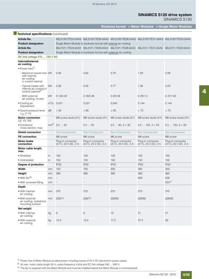
4/39Siemens NC 82 · 2015
SINAMICS S120 drive systemSINAMICS S120
Booksize format > Motor Modules > Single Motor Modules
4
■ Technical specifications (continued)
Article No. 6SL31201TE24-5AA3 6SL31201TE26-0AA3 6SL31201TE28-5AA3 6SL31201TE31-3AA3 6SL31201TE32-0AA4
Product designation Single Motor Module in booksize format with internal air cooling
Article No. 6SL3121-1TE24-5AA3 6SL3121-1TE26-0AA3 6SL3121-1TE28-5AA3 6SL3121-1TE31-3AA3 6SL3121-1TE32-0AA4
Product designation Single Motor Module in booksize format with external air cooling
DC link voltage 510 … 720 V DC
Internal/external air cooling
• Power loss1)
- Maximum power loss with internal air cooling in control cabinet
kW 0.46 0.62 0.79 1.29 2.09
- Typical losses with internal air cooling in control cabinet2)
kW 0.38 0.55 0.77 1.26 2.03
- With external air cooling, int./ext
kW 0.14/0.32 0.16/0.46 0.2/0.59 0.29/1.0 0.47/1.62
• Cooling air requirement
m3/s 0.031 0.031 0.044 0.144 0.144
• Sound pressure levelLpA (1 m)
dB < 65 < 65 < 60 < 73 < 73
Motor connectionU2, V2, W2
M6 screw studs (X1) M6 screw studs (X1) M8 screw studs (X1) M8 screw studs (X1) M8 screw studs (X1)
• Conductor cross-section, max.
mm2 2.5 … 50 2.5 … 50 2.5 … 95, 2 × 35 2.5 … 120, 2 × 50 2.5 … 120, 2 × 50
Shield connection See Accessories See Accessories See Accessories See Accessories See Accessories
PE connection M6 screw M6 screw M6 screw M8 screw M8 screw
Motor brake connection
Plug-in connector (X11), 24 V DC, 2 A
Plug-in connector (X11), 24 V DC, 2 A
Plug-in connector (X11), 24 V DC, 2 A
Plug-in connector (X11), 24 V DC, 2 A
Plug-in connector (X11), 24 V DC, 2 A
Motor cable length, max.
• Shielded m 100 100 100 100 100
• Unshielded m 150 150 150 150 150
Degree of protection IP20 IP20 IP20 IP20 IP20
Width mm 150 150 200 300 300
Height mm 380 380 380 380 380
• With fan3) mm – – – 629 629
• With screwed fitting mm – – – – 5531)
Depth
• With internal air cooling
mm 270 270 270 270 270
• With external air cooling, on/behind mounting surface
mm 226/71 226/71 226/92 226/82 226/82
Net weight
• With internal air cooling
kg 9 9 15 21 21
• With external air cooling
kg 13.2 13.4 17.2 27.2 30
1) Power loss of Motor Module at rated power including losses of 24 V DC electronics power supply.2) At max. motor cable length 30 m, pulse frequency 4 kHz and DC link voltage 540 … 600 V.3) The fan is supplied with the Motor Module and must be installed before the Motor Module is commissioned.
© Siemens AG 2015
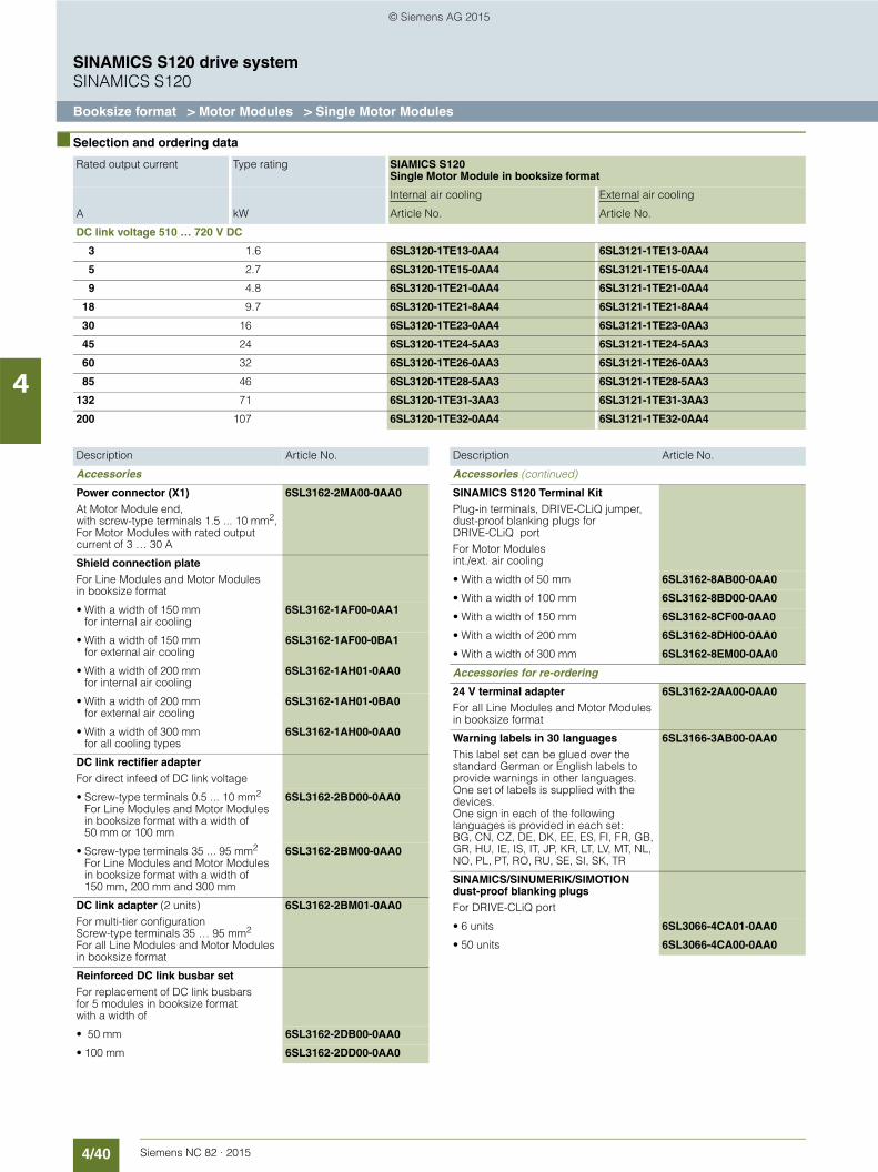
4/40 Siemens NC 82 · 2015
SINAMICS S120 drive systemSINAMICS S120
Booksize format > Motor Modules > Single Motor Modules
4
■ Selection and ordering data
Rated output current Type rating SIAMICS S120Single Motor Module in booksize format
Internal air cooling External air cooling
A kW Article No. Article No.
DC link voltage 510 … 720 V DC
3 1.6 6SL3120-1TE13-0AA4 6SL3121-1TE13-0AA4
5 2.7 6SL3120-1TE15-0AA4 6SL3121-1TE15-0AA4
9 4.8 6SL3120-1TE21-0AA4 6SL3121-1TE21-0AA4
18 9.7 6SL3120-1TE21-8AA4 6SL3121-1TE21-8AA4
30 16 6SL3120-1TE23-0AA4 6SL3121-1TE23-0AA3
45 24 6SL3120-1TE24-5AA3 6SL3121-1TE24-5AA3
60 32 6SL3120-1TE26-0AA3 6SL3121-1TE26-0AA3
85 46 6SL3120-1TE28-5AA3 6SL3121-1TE28-5AA3
132 71 6SL3120-1TE31-3AA3 6SL3121-1TE31-3AA3
200 107 6SL3120-1TE32-0AA4 6SL3121-1TE32-0AA4
Description Article No.
Accessories
Power connector (X1)At Motor Module end, with screw-type terminals 1.5 ... 10 mm2,For Motor Modules with rated output current of 3 … 30 A
6SL3162-2MA00-0AA0
Shield connection plateFor Line Modules and Motor Modules in booksize format
• With a width of 150 mm for internal air cooling
6SL3162-1AF00-0AA1
• With a width of 150 mmfor external air cooling
6SL3162-1AF00-0BA1
• With a width of 200 mm for internal air cooling
6SL3162-1AH01-0AA0
• With a width of 200 mmfor external air cooling
6SL3162-1AH01-0BA0
• With a width of 300 mmfor all cooling types
6SL3162-1AH00-0AA0
DC link rectifier adapterFor direct infeed of DC link voltage
• Screw-type terminals 0.5 ... 10 mm2
For Line Modules and Motor Modules in booksize format with a width of 50 mm or 100 mm
6SL3162-2BD00-0AA0
• Screw-type terminals 35 ... 95 mm2
For Line Modules and Motor Modules in booksize format with a width of 150 mm, 200 mm and 300 mm
6SL3162-2BM00-0AA0
DC link adapter (2 units)For multi-tier configurationScrew-type terminals 35 … 95 mm2
For all Line Modules and Motor Modules in booksize format
6SL3162-2BM01-0AA0
Reinforced DC link busbar setFor replacement of DC link busbars for 5 modules in booksize format with a width of
• 50 mm 6SL3162-2DB00-0AA0
• 100 mm 6SL3162-2DD00-0AA0
Accessories (continued)
SINAMICS S120 Terminal KitPlug-in terminals, DRIVE-CLiQ jumper, dust-proof blanking plugs for DRIVE-CLiQ portFor Motor Modules int./ext. air cooling
• With a width of 50 mm 6SL3162-8AB00-0AA0
• With a width of 100 mm 6SL3162-8BD00-0AA0
• With a width of 150 mm 6SL3162-8CF00-0AA0
• With a width of 200 mm 6SL3162-8DH00-0AA0
• With a width of 300 mm 6SL3162-8EM00-0AA0
Accessories for re-ordering
24 V terminal adapterFor all Line Modules and Motor Modules in booksize format
6SL3162-2AA00-0AA0
Warning labels in 30 languagesThis label set can be glued over the standard German or English labels to provide warnings in other languages.One set of labels is supplied with the devices.One sign in each of the following languages is provided in each set:BG, CN, CZ, DE, DK, EE, ES, FI, FR, GB, GR, HU, IE, IS, IT, JP, KR, LT, LV, MT, NL, NO, PL, PT, RO, RU, SE, SI, SK, TR
6SL3166-3AB00-0AA0
SINAMICS/SINUMERIK/SIMOTION dust-proof blanking plugsFor DRIVE-CLiQ port
• 6 units 6SL3066-4CA01-0AA0
• 50 units 6SL3066-4CA00-0AA0
Description Article No.
© Siemens AG 2015
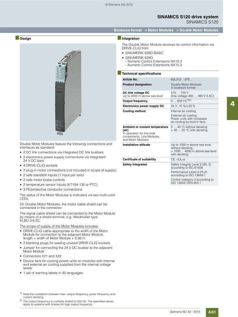
4/41Siemens NC 82 · 2015
SINAMICS S120 drive systemSINAMICS S120
Booksize format > Motor Modules > Double Motor Modules
4
■ Design
Double Motor Modules feature the following connections and interfaces as standard:• 2 DC link connections via integrated DC link busbars• 2 electronics power supply connections via integrated
24 V DC bars• 4 DRIVE-CLiQ sockets• 2 plug-in motor connections (not included in scope of supply)• 2 safe standstill inputs (1 input per axis)• 2 safe motor brake controls• 2 temperature sensor inputs (KTY84-130 or PTC)• 3 PE/protective conductor connections
The status of the Motor Modules is indicated via two multi-color LEDs.
On Double Motor Modules, the motor cable shield can be connected in the connector.
The signal cable shield can be connected to the Motor Module by means of a shield terminal, e.g. Weidmüller type KLBÜ 3-8 SC.
The scope of supply of the Motor Modules includes:• DRIVE-CLiQ cable appropriate to the width of the Motor
Module for connection to the adjacent Motor Module, length = width of Motor Module + 0.06 m
• 2 blanking plugs for sealing unused DRIVE-CLiQ sockets• Jumper for connecting the 24 V DC busbar to the adjacent
Motor Module• Connectors X21 and X22• Device fans for cooling power units on modules with internal
and external air cooling supplied from the internal voltage levels
• 1 set of warning labels in 30 languages
■ Integration
The Double Motor Module receives its control information via DRIVE-CLiQ from:• SINUMERIK 828D BASIC• SINUMERIK 828D
- Numeric Control Extensions NX10.3- Numeric Control Extensions NX15.3
■ Technical specifications
1) Note the correlation between max. output frequency, pulse frequency and current derating.
2) The output frequency is currently limited to 550 Hz. The specified values apply to systems with license for high output frequency.
Article No. 6SL312 . -2TE...
Product designation Double Motor Modules in booksize format
DC link voltage DCUp to 2000 m above sea level
510 … 720 V(line voltage 380 … 480 V 3 AC)
Output frequency 0 … 650 Hz1)2)
Electronics power supply DC 24 V -15 %/+20 %
Cooling method Internal air coolingExternal air cooling,Power units with increased air cooling by built-in fans
Ambient or coolant temperature (air)In operation for line-side components, Line Modules, and Motor Modules
0 … 40 °C without derating> 40 … 55 °C with derating
Installation altitude Up to 1000 m above sea level without derating,> 1000 ... 4000 m above sea level with derating
Certificate of suitability CE, cULus
Safety Integrated Safety Integrity Level 2 (SIL 2) according to IEC 61508,Performance Level d (PLd) according to ISO 13849-1Control category 3 according to ISO 13849-1/EN 954-1
© Siemens AG 2015
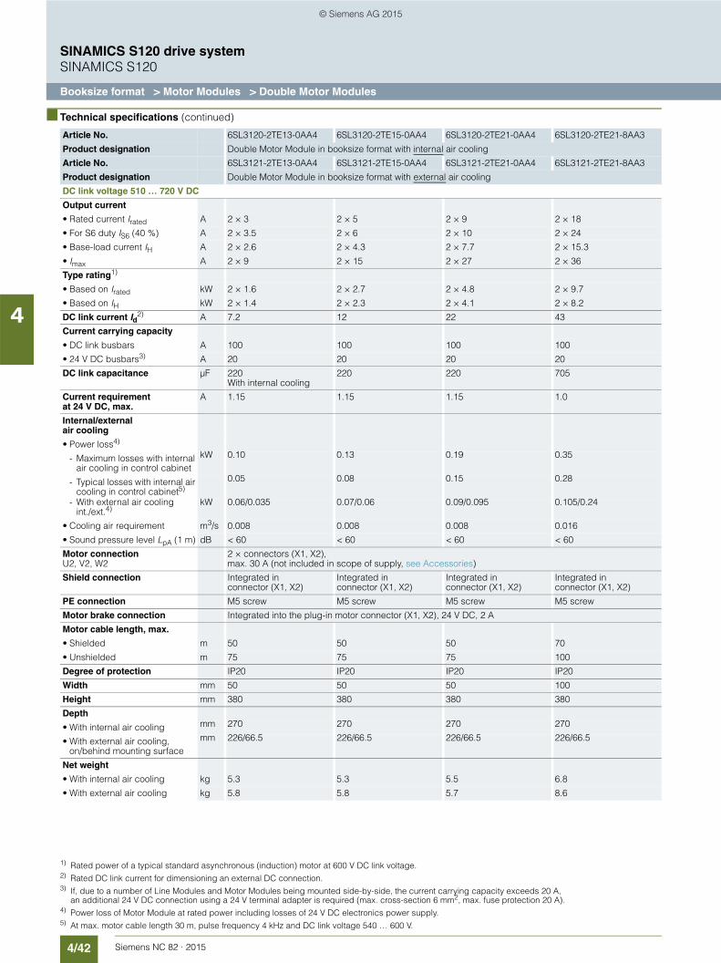
4/42 Siemens NC 82 · 2015
SINAMICS S120 drive systemSINAMICS S120
Booksize format > Motor Modules > Double Motor Modules
4
■ Technical specifications (continued)
Article No. 6SL3120-2TE13-0AA4 6SL3120-2TE15-0AA4 6SL3120-2TE21-0AA4 6SL3120-2TE21-8AA3
Product designation Double Motor Module in booksize format with internal air cooling
Article No. 6SL3121-2TE13-0AA4 6SL3121-2TE15-0AA4 6SL3121-2TE21-0AA4 6SL3121-2TE21-8AA3
Product designation Double Motor Module in booksize format with external air cooling
DC link voltage 510 … 720 V DC
Output current
• Rated current Irated A 2 × 3 2 × 5 2 × 9 2 × 18
• For S6 duty IS6 (40 %) A 2 × 3.5 2 × 6 2 × 10 2 × 24
• Base-load current IH A 2 × 2.6 2 × 4.3 2 × 7.7 2 × 15.3
• Imax A 2 × 9 2 × 15 2 × 27 2 × 36
Type rating1)
• Based on Irated kW 2 × 1.6 2 × 2.7 2 × 4.8 2 × 9.7
• Based on IH kW 2 × 1.4 2 × 2.3 2 × 4.1 2 × 8.2
DC link current Id2) A 7.2 12 22 43
Current carrying capacity
• DC link busbars A 100 100 100 100
• 24 V DC busbars3) A 20 20 20 20
DC link capacitance µF 220 With internal cooling
220 220 705
Current requirement at 24 V DC, max.
A 1.15 1.15 1.15 1.0
Internal/external air cooling
• Power loss4)
- Maximum losses with internal air cooling in control cabinet
kW 0.10 0.13 0.19 0.35
- Typical losses with internal air cooling in control cabinet5)
0.05 0.08 0.15 0.28
- With external air cooling int./ext.4)
kW 0.06/0.035 0.07/0.06 0.09/0.095 0.105/0.24
• Cooling air requirement m3/s 0.008 0.008 0.008 0.016
• Sound pressure level LpA (1 m) dB < 60 < 60 < 60 < 60
Motor connectionU2, V2, W2
2 × connectors (X1, X2),max. 30 A (not included in scope of supply, see Accessories)
Shield connection Integrated in connector (X1, X2)
Integrated in connector (X1, X2)
Integrated in connector (X1, X2)
Integrated in connector (X1, X2)
PE connection M5 screw M5 screw M5 screw M5 screw
Motor brake connection Integrated into the plug-in motor connector (X1, X2), 24 V DC, 2 A
Motor cable length, max.
• Shielded m 50 50 50 70
• Unshielded m 75 75 75 100
Degree of protection IP20 IP20 IP20 IP20
Width mm 50 50 50 100
Height mm 380 380 380 380
Depth
• With internal air cooling mm 270 270 270 270
• With external air cooling, on/behind mounting surface
mm 226/66.5 226/66.5 226/66.5 226/66.5
Net weight
• With internal air cooling kg 5.3 5.3 5.5 6.8
• With external air cooling kg 5.8 5.8 5.7 8.6
1) Rated power of a typical standard asynchronous (induction) motor at 600 V DC link voltage.2) Rated DC link current for dimensioning an external DC connection.3) If, due to a number of Line Modules and Motor Modules being mounted side-by-side, the current carrying capacity exceeds 20 A,
an additional 24 V DC connection using a 24 V terminal adapter is required (max. cross-section 6 mm2, max. fuse protection 20 A).4) Power loss of Motor Module at rated power including losses of 24 V DC electronics power supply.5) At max. motor cable length 30 m, pulse frequency 4 kHz and DC link voltage 540 … 600 V.
© Siemens AG 2015
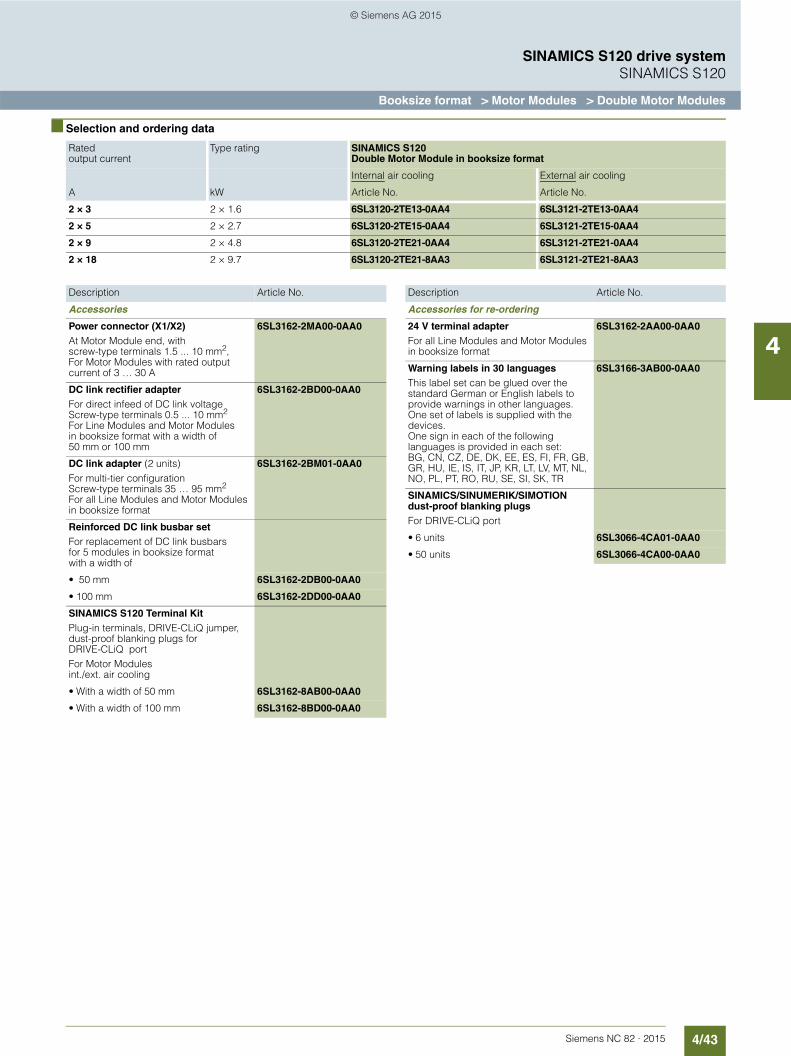
4/43Siemens NC 82 · 2015
SINAMICS S120 drive systemSINAMICS S120
Booksize format > Motor Modules > Double Motor Modules
4
■ Selection and ordering data
Rated output current
Type rating SINAMICS S120 Double Motor Module in booksize format
Internal air cooling External air cooling
A kW Article No. Article No.
2 × 3 2 × 1.6 6SL3120-2TE13-0AA4 6SL3121-2TE13-0AA4
2 × 5 2 × 2.7 6SL3120-2TE15-0AA4 6SL3121-2TE15-0AA4
2 × 9 2 × 4.8 6SL3120-2TE21-0AA4 6SL3121-2TE21-0AA4
2 × 18 2 × 9.7 6SL3120-2TE21-8AA3 6SL3121-2TE21-8AA3
Description Article No.
Accessories
Power connector (X1/X2)At Motor Module end, with screw-type terminals 1.5 ... 10 mm2,For Motor Modules with rated output current of 3 … 30 A
6SL3162-2MA00-0AA0
DC link rectifier adapterFor direct infeed of DC link voltageScrew-type terminals 0.5 ... 10 mm2
For Line Modules and Motor Modules in booksize format with a width of 50 mm or 100 mm
6SL3162-2BD00-0AA0
DC link adapter (2 units)For multi-tier configurationScrew-type terminals 35 … 95 mm2
For all Line Modules and Motor Modules in booksize format
6SL3162-2BM01-0AA0
Reinforced DC link busbar setFor replacement of DC link busbars for 5 modules in booksize format with a width of
• 50 mm 6SL3162-2DB00-0AA0
• 100 mm 6SL3162-2DD00-0AA0
SINAMICS S120 Terminal KitPlug-in terminals, DRIVE-CLiQ jumper, dust-proof blanking plugs for DRIVE-CLiQ portFor Motor Modules int./ext. air cooling
• With a width of 50 mm 6SL3162-8AB00-0AA0
• With a width of 100 mm 6SL3162-8BD00-0AA0
Accessories for re-ordering
24 V terminal adapterFor all Line Modules and Motor Modules in booksize format
6SL3162-2AA00-0AA0
Warning labels in 30 languagesThis label set can be glued over the standard German or English labels to provide warnings in other languages.One set of labels is supplied with the devices.One sign in each of the following languages is provided in each set:BG, CN, CZ, DE, DK, EE, ES, FI, FR, GB, GR, HU, IE, IS, IT, JP, KR, LT, LV, MT, NL, NO, PL, PT, RO, RU, SE, SI, SK, TR
6SL3166-3AB00-0AA0
SINAMICS/SINUMERIK/SIMOTION dust-proof blanking plugsFor DRIVE-CLiQ port
• 6 units 6SL3066-4CA01-0AA0
• 50 units 6SL3066-4CA00-0AA0
Description Article No.
© Siemens AG 2015

4/44 Siemens NC 82 · 2015
SINAMICS S120 drive systemSINAMICS S120
Booksize format > Motor Modules > Series motor reactors
4
■ Overview
Series motor reactor
A series reactor in the form of a three-limb iron-cored reactor may be required in the case of special motors with minimal leak-age inductance (for which the controller settings are insufficient). Motors with a low leakage inductance are, from experience, motors that can achieve high stator frequencies > 300 Hz or motors with a high rated current > 85 A.
The series motor reactors are designed for a pulse frequency of 4 kHz or 8 kHz output from the Motor Module. Higher pulse frequencies are not permissible.
■ Overview (continued)
The series motor reactor must be installed as close as possible to the Motor Module.
The voltage drop across a series reactor depends on the motor current and the motor frequency. If an unregulated infeed is used, the maximum rated motor voltage depends on the line supply voltage available. If these guide values are observed, lower reductions in power in the upper speed range of the motor can be achieved.
The surface temperature of the series motor reactor can reach up to 100 °C. This additional heat source must be taken into account in the system.
The notes in the Configuration Manual for the motors used must be observed.
■ Selection and ordering data
■ Technical specifications
Suitable forMotor Module in booksize formatInternal air coolingExternal air cooling
Series motor reactor
Rated current
Rated induc-tance
Type A mH Article No.
6SL3120-...6SL3121-...
22.5 0.3 4EU2552-0EF00-4BA0
6SL3120-...6SL3121-...
108 0.1 4EU3951-0AR00-4B
Article No. 4EU2552-0EF00-4BA0 4EU3951-0AR00-4B
Product designation Series motor reactor Series motor reactor
Input voltage 380 ... 480 V 3 AC (DC link voltage 510 ... 720 V DC)
Rated current A 22.5 108
Rated inductance mH 0.3 0.1
Power loss W 146 454
Continuous current Ithmax, therm. perm.
A 25 120
Continuous frequency, therm. perm.
Hz 1400 1400
Pulse frequency, max. kHz 8 8
Relative voltage drop at the series motor reactorAt Ithmax and Vrated
% 23 38
Ambient temperature °C 40 40
Connection to Motor Module/motor
Flat-type terminal Flat-type terminal
PE connection M6 screw M8 screw
Degree of protection IP00 IP00
Width mm 225 410
Height mm 210 385
Depth mm 115 174
Net weight kg 16 68
Certificate of suitability cURus cURus
© Siemens AG 2015

4/45Siemens NC 82 · 2015
SINAMICS S120 drive systemSINAMICS S120
Booksize format > DC link components > Braking Module
4
■ Overview1)
Braking Module
A Braking Module and the matching external braking resistor are required to bring drives to a controlled standstill in the event of a power failure (e.g. emergency retraction or EMERGENCY STOP category 1) or limit the DC link voltage for brief periods of gen-erator operation, e.g. when the regenerative feedback capability of the Line Module is deactivated. The Braking Module includes the power electronics and the associated control circuit. During operation, the DC link power is converted into heat loss in an external braking resistor. Braking Modules function autono-mously.
Braking Modules in booksize format can also be used for rapid discharge of the DC link.
■ Design
The Braking Module in booksize format features the following connections and interfaces as standard:• 2 DC link connections via integrated DC link busbars• 2 electronics power supply connections via integrated
24 V DC bars• Terminals for connecting the braking resistor• 2 digital inputs (disable Braking Module/acknowledge faults
and rapid discharge of DC link)• 2 digital outputs (Braking Module disabled and
prewarning I × t monitoring)• 2 PE/protective conductor connections
The status of the Braking Module is indicated via two 2-color LEDs.
■ Technical specifications
■ Selection and ordering data
1) Several Braking Modules can be operated in parallel, typically up to 4 Modules
Article No. 6SL3100-1AE31-0AB1
Product designation Braking Module in booksize format with internal air cooling
DC link voltage 510 … 720 V DC
Rated power PDB 1.5 kW1)
Peak power Pmax 100 kW1)
Activation threshold 770 V
Cable lengthTo braking resistor, max.
10 m
DC link capacitance 110 µF
Current requirement at 24 V DC, max. 0.5 A
Digital inputsin accordance with IEC 61131-2 Type 1
• Voltage -3 … +30 V
• Low level (an open digital input is interpreted as Low)
-3 … +5 V
• High level 15 … 30 V
• Current consumption at 24 V DC, typ. 10 mA
• Conductor cross-section, max. 1.5 mm2
Digital outputs Sustained short-circuit proof
• Voltage DC 24 V
• Load current per digital output, max. 100 mA
• Conductor cross-section, max. 1.5 mm2
Current carrying capacity
• 24 V DC busbars 20 A
• DC link busbars 100 A
PE connection M5 screw
Width 50 mm
Height 380 mm
Depth with spacer 270 mm
Net weight 4.1 kg
Certificate of suitability cURus
Description Article No.
Braking Module in booksize formatInternal air cooling, incl. spacer
6SL3100-1AE31-0AB1
Accessories for re-ordering
Warning labels in 30 languagesThis label set can be glued over the standard German or English labels to provide warnings in other languages.One set of labels is supplied with the devices.One sign in each of the following languages is provided in each set:BG, CN, CZ, DE, DK, EE, ES, FI, FR, GB, GR, HU, IE, IS, IT, JP, KR, LT, LV, MT, NL, NO, PL, PT, RO, RU, SE, SI, SK, TR
6SL3166-3AB00-0AA0
© Siemens AG 2015
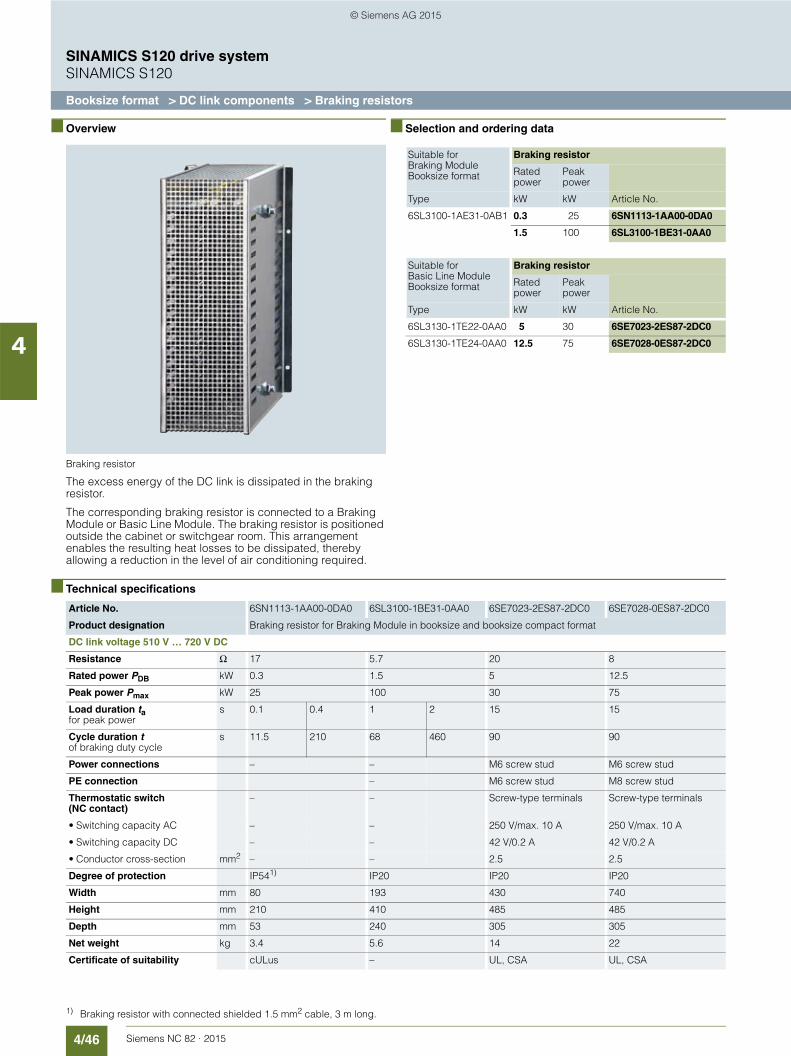
4/46 Siemens NC 82 · 2015
SINAMICS S120 drive systemSINAMICS S120
Booksize format > DC link components > Braking resistors
4
■ Overview
Braking resistor
The excess energy of the DC link is dissipated in the braking resistor.
The corresponding braking resistor is connected to a Braking Module or Basic Line Module. The braking resistor is positioned outside the cabinet or switchgear room. This arrangement enables the resulting heat losses to be dissipated, thereby allowing a reduction in the level of air conditioning required.
■ Selection and ordering data
■ Technical specifications
Suitable forBraking ModuleBooksize format
Braking resistor
Rated power
Peak power
Type kW kW Article No.
6SL3100-1AE31-0AB1 0.3 25 6SN1113-1AA00-0DA0
1.5 100 6SL3100-1BE31-0AA0
Suitable forBasic Line ModuleBooksize format
Braking resistor
Rated power
Peak power
Type kW kW Article No.
6SL3130-1TE22-0AA0 5 30 6SE7023-2ES87-2DC0
6SL3130-1TE24-0AA0 12.5 75 6SE7028-0ES87-2DC0
Article No. 6SN1113-1AA00-0DA0 6SL3100-1BE31-0AA0 6SE7023-2ES87-2DC0 6SE7028-0ES87-2DC0
Product designation Braking resistor for Braking Module in booksize and booksize compact format
DC link voltage 510 V … 720 V DC
Resistance Ω 17 5.7 20 8
Rated power PDB kW 0.3 1.5 5 12.5
Peak power Pmax kW 25 100 30 75
Load duration tafor peak power
s 0.1 0.4 1 2 15 15
Cycle duration tof braking duty cycle
s 11.5 210 68 460 90 90
Power connections – – M6 screw stud M6 screw stud
PE connection – M6 screw stud M8 screw stud
Thermostatic switch (NC contact)
– – Screw-type terminals Screw-type terminals
• Switching capacity AC – – 250 V/max. 10 A 250 V/max. 10 A
• Switching capacity DC – – 42 V/0.2 A 42 V/0.2 A
• Conductor cross-section mm2 – – 2.5 2.5
Degree of protection IP541) IP20 IP20 IP20
Width mm 80 193 430 740
Height mm 210 410 485 485
Depth mm 53 240 305 305
Net weight kg 3.4 5.6 14 22
Certificate of suitability cULus – UL, CSA UL, CSA
1) Braking resistor with connected shielded 1.5 mm2 cable, 3 m long.
© Siemens AG 2015

4/47Siemens NC 82 · 2015
SINAMICS S120 drive systemSINAMICS S120
Booksize format > DC link components > Capacitor Module
4
■ Overview
Capacitor Module
The Capacitor Module is used to increase the DC link capaci-tance to bridge momentary power losses.
The Capacitor Module is connected to the DC link voltage via the integrated DC link busbars. The Capacitor Module functions autonomously.
Several Capacitor Modules can be operated in parallel.
■ Design
Capacitor Modules feature the following connections and interfaces as standard:• 2 DC link connections via integrated DC link busbars• 2 PE/protective conductor connections
■ Technical specifications
■ Selection and ordering data
Article No. 6SL3100-1CE14-0AA0
Product designation Capacitor Modulein booksize format
DC link voltage 510 … 720 V DC
Capacitance 4000 µF
Current carrying capacity
• 24 V DC busbars 20 A
• DC link busbars 100 A
PE connection M5 screw
Width 100 mm
Height 380 mm
Depth, with spacer 270 mm
Net weight 7.2 kg
Certificate of suitability cULus
Description Article No.
Capacitor Modulein booksize formatInternal air cooling, incl. spacer
6SL3100-1CE14-0AA0
Accessories for re-ordering
Warning labels in 30 languagesThis label set can be glued over the standard German or English labels to provide warnings in other languages.One set of labels is supplied with the devices.One sign in each of the following languages is provided in each set:BG, CN, CZ, DE, DK, EE, ES, FI, FR, GB, GR, HU, IE, IS, IT, JP, KR, LT, LV, MT, NL, NO, PL, PT, RO, RU, SE, SI, SK, TR
6SL3166-3AB00-0AA0
© Siemens AG 2015
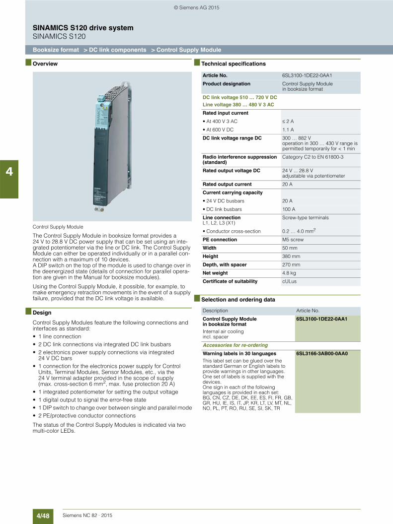
4/48 Siemens NC 82 · 2015
SINAMICS S120 drive systemSINAMICS S120
Booksize format > DC link components > Control Supply Module
4
■ Overview
Control Supply Module
The Control Supply Module in booksize format provides a 24 V to 28.8 V DC power supply that can be set using an inte-grated potentiometer via the line or DC link. The Control Supply Module can either be operated individually or in a parallel con-nection with a maximum of 10 devices. A DIP switch on the top of the module is used to change over in the deenergized state (details of connection for parallel opera-tion are given in the Manual for booksize modules).
Using the Control Supply Module, it possible, for example, to make emergency retraction movements in the event of a supply failure, provided that the DC link voltage is available.
■ Design
Control Supply Modules feature the following connections and interfaces as standard:• 1 line connection• 2 DC link connections via integrated DC link busbars• 2 electronics power supply connections via integrated
24 V DC bars• 1 connection for the electronics power supply for Control
Units, Terminal Modules, Sensor Modules, etc., via the 24 V terminal adapter provided in the scope of supply (max. cross-section 6 mm2, max. fuse protection 20 A)
• 1 integrated potentiometer for setting the output voltage• 1 digital output to signal the error-free state• 1 DIP switch to change over between single and parallel mode• 2 PE/protective conductor connections
The status of the Control Supply Modules is indicated via two multi-color LEDs.
■ Technical specifications
■ Selection and ordering data
Article No. 6SL3100-1DE22-0AA1
Product designation Control Supply Module in booksize format
DC link voltage 510 … 720 V DCLine voltage 380 … 480 V 3 AC
Rated input current
• At 400 V 3 AC ≤ 2 A
• At 600 V DC 1.1 A
DC link voltage range DC 300 … 882 Voperation in 300 … 430 V range is permitted temporarily for < 1 min
Radio interference suppression (standard)
Category C2 to EN 61800-3
Rated output voltage DC 24 V ... 28.8 V adjustable via potentiometer
Rated output current 20 A
Current carrying capacity
• 24 V DC busbars 20 A
• DC link busbars 100 A
Line connectionL1, L2, L3 (X1)
Screw-type terminals
• Conductor cross-section 0.2 … 4.0 mm2
PE connection M5 screw
Width 50 mm
Height 380 mm
Depth, with spacer 270 mm
Net weight 4.8 kg
Certificate of suitability cULus
Description Article No.
Control Supply Module in booksize formatInternal air coolingincl. spacer
6SL3100-1DE22-0AA1
Accessories for re-ordering
Warning labels in 30 languagesThis label set can be glued over the standard German or English labels to provide warnings in other languages.One set of labels is supplied with the devices.One sign in each of the following languages is provided in each set:BG, CN, CZ, DE, DK, EE, ES, FI, FR, GB, GR, HU, IE, IS, IT, JP, KR, LT, LV, MT, NL, NO, PL, PT, RO, RU, SE, SI, SK, TR
6SL3166-3AB00-0AA0
© Siemens AG 2015
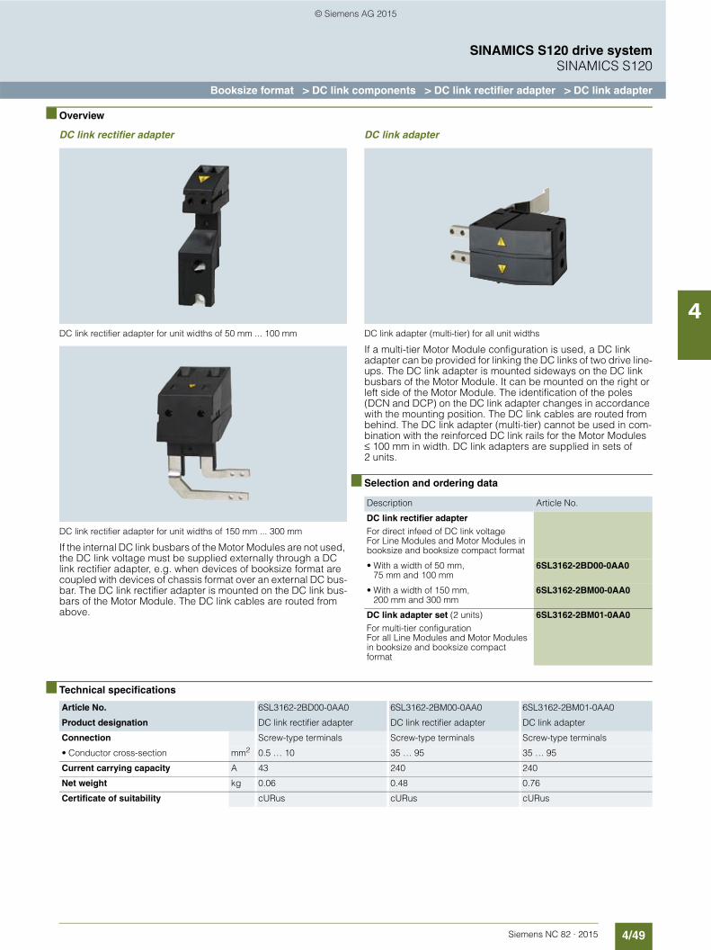
4/49Siemens NC 82 · 2015
SINAMICS S120 drive systemSINAMICS S120
Booksize format > DC link components > DC link rectifier adapter > DC link adapter
4
■ Overview
DC link rectifier adapter
DC link rectifier adapter for unit widths of 50 mm ... 100 mm
DC link rectifier adapter for unit widths of 150 mm ... 300 mm
If the internal DC link busbars of the Motor Modules are not used, the DC link voltage must be supplied externally through a DC link rectifier adapter, e.g. when devices of booksize format are coupled with devices of chassis format over an external DC bus-bar. The DC link rectifier adapter is mounted on the DC link bus-bars of the Motor Module. The DC link cables are routed from above.
DC link adapter
DC link adapter (multi-tier) for all unit widths
If a multi-tier Motor Module configuration is used, a DC link adapter can be provided for linking the DC links of two drive line-ups. The DC link adapter is mounted sideways on the DC link busbars of the Motor Module. It can be mounted on the right or left side of the Motor Module. The identification of the poles (DCN and DCP) on the DC link adapter changes in accordance with the mounting position. The DC link cables are routed from behind. The DC link adapter (multi-tier) cannot be used in com-bination with the reinforced DC link rails for the Motor Modules ≤ 100 mm in width. DC link adapters are supplied in sets of 2 units.
■ Selection and ordering data
■ Technical specifications
Description Article No.
DC link rectifier adapterFor direct infeed of DC link voltageFor Line Modules and Motor Modules in booksize and booksize compact format
• With a width of 50 mm, 75 mm and 100 mm
6SL3162-2BD00-0AA0
• With a width of 150 mm, 200 mm and 300 mm
6SL3162-2BM00-0AA0
DC link adapter set (2 units)For multi-tier configurationFor all Line Modules and Motor Modules in booksize and booksize compact format
6SL3162-2BM01-0AA0
Article No. 6SL3162-2BD00-0AA0 6SL3162-2BM00-0AA0 6SL3162-2BM01-0AA0
Product designation DC link rectifier adapter DC link rectifier adapter DC link adapter
Connection Screw-type terminals Screw-type terminals Screw-type terminals
• Conductor cross-section mm2 0.5 … 10 35 … 95 35 … 95
Current carrying capacity A 43 240 240
Net weight kg 0.06 0.48 0.76
Certificate of suitability cURus cURus cURus
© Siemens AG 2015
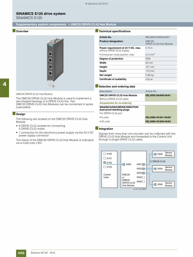
4/50 Siemens NC 82 · 2015
SINAMICS S120 drive systemSINAMICS S120
Supplementary system components > DMC20 DRIVE-CLiQ Hub Module
4
■ Overview
DMC20 DRIVE-CLiQ Hub Module
The DMC20 DRIVE-CLiQ Hub Module is used to implement a star-shaped topology of a DRIVE-CLiQ line. Two DMC20 DRIVE-CLiQ Hub Modules can be connected in series (cascaded).
■ Design
The following are located on the DMC20 DRIVE-CLiQ Hub Module:• 6 DRIVE-CLiQ sockets for connecting
5 DRIVE-CLiQ nodes• 1 connection for the electronics power supply via the 24 V DC
power supply connector
The status of the DMC20 DRIVE-CLiQ Hub Module is indicated via a multi-color LED.
■ Technical specifications
■ Selection and ordering data
■ Integration
Signals from more than one encoder can be collected with the DRIVE-CLiQ Hub Module and forwarded to the Control Unit through a single DRIVE-CLiQ cable.
Article No. 6SL3055-0AA00-6AA1
Product designation DMC20DRIVE-CLiQ Hub Module
Power requirement at 24 V DC, max.without DRIVE-CLiQ supply
0.15 A
• Conductor cross-section, max. 2.5 mm2
Degree of protection IP20
Width 50 mm
Height 151 mm
Depth 110 mm
Net weight 0.36 kg
Certificate of suitability cULus
Description Article No.
DMC20 DRIVE-CLiQ Hub Module Without DRIVE-CLiQ cable
6SL3055-0AA00-6AA1
Accessories for re-ordering
SINAMICS/SINUMERIK/SIMOTION dust-proof blanking plugsFor DRIVE-CLiQ port
• 6 units 6SL3066-4CA01-0AA0
• 50 units 6SL3066-4CA00-0AA0
G_D211_EN_00067c
DMC20orDME20DRIVE-CLiQHub Module
ControlUnits
SensorModule
SensorModule
SensorModule
X103
X102
X101
X505
X504
X503
X502
X501
X500
X500
X100
DRIVE-CLiQ
X500
X500
© Siemens AG 2015

4/51Siemens NC 82 · 2015
SINAMICS S120 drive systemSINAMICS S120
Supplementary system components > DME20 DRIVE-CLiQ Hub Module
4
■ Overview
DME20 DRIVE-CLiQ Hub Module
The DME20 DRIVE-CLiQ Hub Module is used to implement a star-shaped distribution of a DRIVE-CLiQ line. Two DME20 DRIVE-CLiQ Hub Modules can be connected in series (cascaded).
■ Design
The following are located on the DME20 DRIVE-CLiQ Hub Module:• 6 DRIVE-CLiQ sockets for connecting 5 DRIVE-CLiQ nodes• 1 connection for the electronics power supply via the 24 V DC
circular power supply connector with conductor cross-section 4 × 0.75 mm2 (pins 1+2 internally bridged; pins 3+4 internally bridged)
The scope of supply of the DME20 DRIVE-CLiQ Hub Modules includes:• 6 blanking plugs for sealing unused DRIVE-CLiQ sockets
■ Technical specifications
■ Selection and ordering data
■ Integration
Signals from more than one encoder can be collected with the DRIVE-CLiQ Hub Module and forwarded to the Control Unit through a single DRIVE-CLiQ cable.
Article No. 6SL3055-0AA00-6AB0
Product designation DME20 DRIVE-CLiQ Hub Module
Power requirement at 24 V DC, max.without DRIVE-CLiQ supply
0.15 A
• Conductor cross-section, max. 4 × 0.75 mm2
Degree of protection IP67
Width 99 mm
Height 149 mm
Depth 55.7 mmwithout connector
Net weight 0.8 kg
Certificate of suitability cULus
Description Article No.
DME20 DRIVE-CLiQ Hub Module Without DRIVE CLiQ cable; without electronics power supply cable and circular connector for 24 V DC
6SL3055-0AA00-6AB0
Accessories
24 V DC power supply cable Ordering and delivery Phoenix Contactwww.phoenixcontact.com
• Shielded connector, 5-pole, can be assembled by the user
Art. No. 1508365
• Unshielded connector, 4-pole, can be assembled by the user, Speedcon rapid interlock
Art. No. 1521601
Accessories for re-ordering
SINAMICS/SINUMERIK/SIMOTION dust-proof blanking plugsFor DRIVE-CLiQ port
• 6 units 6SL3066-4CA01-0AA0
• 50 units 6SL3066-4CA00-0AA0
G_D211_EN_00067c
DMC20orDME20DRIVE-CLiQHub Module
ControlUnits
SensorModule
SensorModule
SensorModule
X103
X102
X101
X505
X504
X503
X502
X501
X500
X500
X100
DRIVE-CLiQ
X500
X500
© Siemens AG 2015
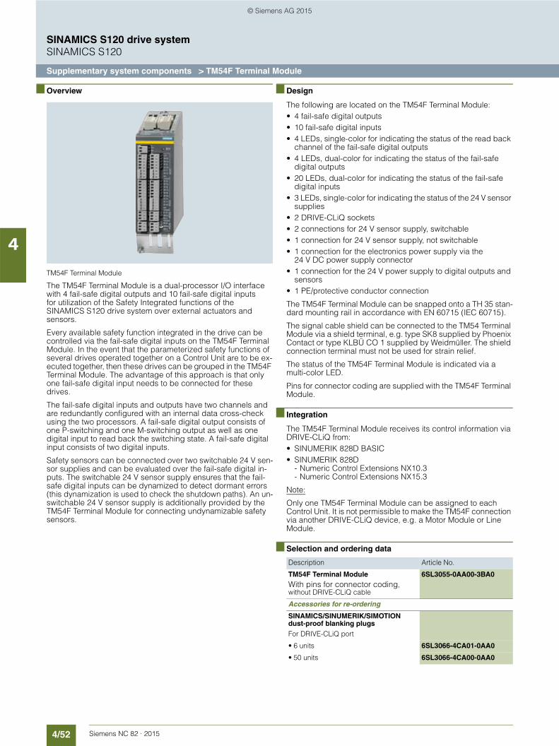
4/52 Siemens NC 82 · 2015
SINAMICS S120 drive systemSINAMICS S120
Supplementary system components > TM54F Terminal Module
4
■ Overview
TM54F Terminal Module
The TM54F Terminal Module is a dual-processor I/O interface with 4 fail-safe digital outputs and 10 fail-safe digital inputs for utilization of the Safety Integrated functions of the SINAMICS S120 drive system over external actuators and sensors.
Every available safety function integrated in the drive can be controlled via the fail-safe digital inputs on the TM54F Terminal Module. In the event that the parameterized safety functions of several drives operated together on a Control Unit are to be ex-ecuted together, then these drives can be grouped in the TM54F Terminal Module. The advantage of this approach is that only one fail-safe digital input needs to be connected for these drives.
The fail-safe digital inputs and outputs have two channels and are redundantly configured with an internal data cross-check using the two processors. A fail-safe digital output consists of one P-switching and one M-switching output as well as one digital input to read back the switching state. A fail-safe digital input consists of two digital inputs.
Safety sensors can be connected over two switchable 24 V sen-sor supplies and can be evaluated over the fail-safe digital in-puts. The switchable 24 V sensor supply ensures that the fail-safe digital inputs can be dynamized to detect dormant errors (this dynamization is used to check the shutdown paths). An un-switchable 24 V sensor supply is additionally provided by the TM54F Terminal Module for connecting undynamizable safety sensors.
■ Design
The following are located on the TM54F Terminal Module:• 4 fail-safe digital outputs• 10 fail-safe digital inputs• 4 LEDs, single-color for indicating the status of the read back
channel of the fail-safe digital outputs• 4 LEDs, dual-color for indicating the status of the fail-safe
digital outputs• 20 LEDs, dual-color for indicating the status of the fail-safe
digital inputs• 3 LEDs, single-color for indicating the status of the 24 V sensor
supplies• 2 DRIVE-CLiQ sockets• 2 connections for 24 V sensor supply, switchable• 1 connection for 24 V sensor supply, not switchable• 1 connection for the electronics power supply via the
24 V DC power supply connector• 1 connection for the 24 V power supply to digital outputs and
sensors• 1 PE/protective conductor connection
The TM54F Terminal Module can be snapped onto a TH 35 stan-dard mounting rail in accordance with EN 60715 (IEC 60715).
The signal cable shield can be connected to the TM54 Terminal Module via a shield terminal, e.g. type SK8 supplied by Phoenix Contact or type KLBÜ CO 1 supplied by Weidmüller. The shield connection terminal must not be used for strain relief.
The status of the TM54F Terminal Module is indicated via a multi-color LED.
Pins for connector coding are supplied with the TM54F Terminal Module.
■ Integration
The TM54F Terminal Module receives its control information via DRIVE-CLiQ from:• SINUMERIK 828D BASIC• SINUMERIK 828D
- Numeric Control Extensions NX10.3- Numeric Control Extensions NX15.3
Note:
Only one TM54F Terminal Module can be assigned to each Control Unit. It is not permissible to make the TM54F connection via another DRIVE-CLiQ device, e.g. a Motor Module or Line Module.
■ Selection and ordering data
Description Article No.
TM54F Terminal ModuleWith pins for connector coding, without DRIVE-CLiQ cable
6SL3055-0AA00-3BA0
Accessories for re-ordering
SINAMICS/SINUMERIK/SIMOTION dust-proof blanking plugsFor DRIVE-CLiQ port
• 6 units 6SL3066-4CA01-0AA0
• 50 units 6SL3066-4CA00-0AA0
© Siemens AG 2015

4/53Siemens NC 82 · 2015
SINAMICS S120 drive systemSINAMICS S120
Supplementary system components > TM54F Terminal Module
4
■ Technical specifications
Article No. 6SL3055-0AA00-3BA0
Product designation TM54F Terminal Module
Power requirement at 24 V DC(X524) without DRIVE-CLiQ supply
0.2 A
• Conductor cross-section, max. 2.5 mm2
• Fuse protection, max. 20 A
Power requirement ext. 24 V, max.For supplying the digital outputs and 24 V sensor supply (X514 at 24 V DC)
4 A
• Conductor cross-section, max. 2.5 mm2
• Fuse protection, max. 20 A
I/O
• Number of fail-safe digital inputs
10
• Number of fail-safe digital outputs
4
• 24 V sensor supply 3of which 2 can be temporarily shut down using an internal test routine for dynamizing fail-safe digital inputs, current carrying capacity 0.5 A each
• Connection method Plug-in screw-type terminals
• Conductor cross-section, max. 1.5 mm2
Digital inputs in accordance with IEC 61131-2 Type 1, with isolation
• Voltage -3 … +30 V
• Low level (an open digital input is interpreted as low)
-3 … +5 V
• High level 15 … 30 V
• Current consumption, typ.
- At 24 V DC > 2 mA
• Delay time of digital inputs, approx.1)
- L → H, typ. 30 µs
- H → L, typ. 60 µs
• Safe state Low level for inputs that can be inverted: without inversion
Digital outputs Sustained short-circuit proof
• Voltage DC 24 V
• Load current per fail-safe digital output, max.2)
0.5 A
• Delay times (resistive load)1)
- L → H, typ. 300 µs
- H → L, typ. 350 µs
• Safe state Output switched off
Scanning cycle tSI
For fail-safe digital inputs or fail-safe digital outputs
4 ... 25 ms adjustable
Power loss at 24 V DC, max. 4.4 W
PE connection M4 screw
Width 50 mm
Height 150 mm
Depth 111 mm
Net weight 0.9 kg
Certificate of suitability cULus
Safety Integrated Safety Integrity Level 2 (SIL2) according to IEC 61508Performance Level d (PLd) according to ISO 13849-1Control category 3 according to ISO 13849-1/EN 954-1
Article No. 6SL3055-0AA00-3BA0
Product designation TM54F Terminal Module
1) The specified delay times refer to the hardware. The actual reaction time depends on the time slot in which the digital input/output is processed.
2) The total current of all fail-safe digital outputs must not exceed 5.33 A.
© Siemens AG 2015

4/54 Siemens NC 82 · 2015
SINAMICS S120 drive systemSINAMICS S120
Supplementary system components > Encoder system connection > SMC20 Sensor Module Cabinet-Mounted
4
■ Overview
SMC20 Sensor Module Cabinet-Mounted
The SMC20 Sensor Module Cabinet-Mounted is required to evaluate the encoder signals of motors without a DRIVE-CLiQ interface. External encoders can also be connected via the SMC20.
The following encoder signals can be evaluated:• Incremental encoder sin/cos 1 Vpp• Absolute encoder EnDat 2.1• SSI encoder with incremental signals sin/cos 1 Vpp
(firmware V2.4 and later)
The motor temperature can also be detected with KTY84-130 or PTC thermistors.
■ Design
The SMC20 Sensor Module Cabinet-Mounted features the following connections and interfaces as standard:• 1 DRIVE-CLiQ interface• 1 encoder connection including motor temperature detection
(KTY84-130 or PTC) via SUB-D connector• 1 connection for the electronics power supply via the
24 V DC power supply connector• 1 PE/protective conductor connection
The status of the SMC20 Sensor Module Cabinet-Mounted is indicated via a multi-color LED.
The SMC20 Sensor Module Cabinet-Mounted can be snapped onto a TH 35 standard mounting rail in accordance with EN 60715 (IEC 60715).
The signal cable shield is connected via the encoder system connector and can also be connected to the SMC20 Sensor Module Cabinet-Mounted via a shield connection terminal, e.g. Phoenix Contact type SK8 or Weidmüller type KLBÜ CO 1. The shield connection terminal must not be used for strain relief.
■ Integration
SMC20 Sensor Modules Cabinet-Mounted communicate with a Control Unit via DRIVE-CLiQ.
■ Technical specifications
■ Selection and ordering data
Article No. 6SL3055-0AA00-5BA3
Product designation SMC20 Sensor Module Cabinet-Mounted
Power requirement at 24 V DC, max.without taking encoder into account
0.2 A
• Conductor cross-section, max. 2.5 mm2
• Fuse protection, max. 20 A
Power loss, max. 10 W
Encoders which can be evaluated
• Incremental encoder sin/cos 1 Vpp
• Absolute encoder EnDat• SSI encoder with incremental
signals sin/cos 1 Vpp (firmware V2.4 and later)
• Encoder supply DC 5 V/0.35 A
• Encoder frequency incremental signals, max.
500 kHz
• Signal subdivision (interpolation), max.
16384 times (14 bit)
• SSI baud rate 100 kBaud
Cable length to encoder, max. 100 m
PE connection M4 screw
Width 30 mm
Height 150 mm
Depth 111 mm
Net weight 0.45 kg
Certificate of suitability cULus
Description Article No.
SMC20 Sensor Module Cabinet-Mounted Without DRIVE-CLiQ cable
6SL3055-0AA00-5BA3
© Siemens AG 2015
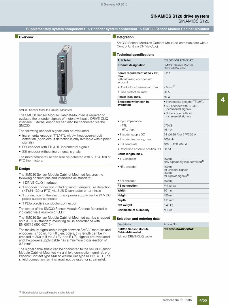
4/55Siemens NC 82 · 2015
SINAMICS S120 drive systemSINAMICS S120
Supplementary system components > Encoder system connection > SMC30 Sensor Module Cabinet-Mounted
4
■ Overview
SMC30 Sensor Module Cabinet-Mounted
The SMC30 Sensor Module Cabinet-Mounted is required to evaluate the encoder signals of motors without a DRIVE-CLiQ interface. External encoders can also be connected via the SMC30.
The following encoder signals can be evaluated:• Incremental encoder TTL/HTL with/without open-circuit
detection (open-circuit detection is only available with bipolar signals)
• SSI encoder with TTL/HTL incremental signals• SSI encoder without incremental signals
The motor temperature can also be detected with KTY84-130 or PTC thermistors.
■ Design
The SMC30 Sensor Module Cabinet-Mounted features the following connections and interfaces as standard:• 1 DRIVE-CLiQ interface• 1 encoder connection including motor temperature detection
(KTY84-130 or PTC) via SUB-D connector or terminals• 1 connection for the electronics power supply via the 24 V DC
power supply connector• 1 PE/protective conductor connection
The status of the SMC30 Sensor Module Cabinet-Mounted is indicated via a multi-color LED.
The SMC30 Sensor Module Cabinet-Mounted can be snapped onto a TH 35 standard mounting rail in accordance with EN 60715 (IEC 60715).
The maximum signal cable length between SMC30 modules and encoders is 100 m. For HTL encoders, this length can be in-creased to 300 m if the A+/A- and B+/B- signals are evaluated and the power supply cable has a minimum cross-section of 0.5 mm2.
The signal cable shield can be connected to the SMC30 Sensor Module Cabinet-Mounted via a shield connection terminal, e.g. Phoenix Contact type SK8 or Weidmüller type KLBÜ CO 1. The shield connection terminal must not be used for strain relief.
■ Integration
SMC30 Sensor Modules Cabinet-Mounted communicate with a Control Unit via DRIVE-CLiQ.
■ Technical specifications
■ Selection and ordering data
Article No. 6SL3055-0AA00-5CA2
Product designation SMC30 Sensor Module Cabinet-Mounted
Power requirement at 24 V DC, max.without taking encoder into account
0.2 A
• Conductor cross-section, max. 2.5 mm2
• Fuse protection, max. 20 A
Power loss, max. 10 W
Encoders which can be evaluated
• Incremental encoder TTL/HTL• SSI encoder with TTL/HTL
incremental signals• SSI encoder without
incremental signals
• Input impedance- TTL- HTL, max.
570 Ω16 mA
• Encoder supply DC 24 V/0.35 A or 5 V/0.35 A
• Encoder frequency, max. 300 kHz
• SSI baud rate 100 … 250 kBaud
• Resolution absolute position SSI 30 bit
Cable length, max.
• TTL encoder 100 m only bipolar signals permitted1)
• HTL encoder 100 m for unipolar signals300 m for bipolar signals1)
• SSI encoder 100 m
PE connection M4 screw
Width 30 mm
Height 150 mm
Depth 111 mm
Net weight 0.45 kg
Certificate of suitability cULus
Description Article No.
SMC30 Sensor Module Cabinet-Mounted Without DRIVE-CLiQ cable
6SL3055-0AA00-5CA2
1) Signal cables twisted in pairs and shielded.
© Siemens AG 2015

4/56 Siemens NC 82 · 2015
SINAMICS S120 drive systemSINAMICS S120
Supplementary system components > Encoder system connection > SMC40 Sensor Module Cabinet-Mounted
4
■ Overview
SMC40 Sensor Module Cabinet-Mounted
The SMC40 Sensor Module Cabinet-Mounted is required to evaluate the encoder signals of motors without a DRIVE-CLiQ interface. External encoders can also be connected via the SMC40.
The following encoder signals can be evaluated:• Absolute encoder EnDat 2.2
■ Design
The SMC40 Sensor Module Cabinet-Mounted features the following connections and interfaces as standard:• 2 DRIVE-CLiQ interfaces• 2 encoder system interfaces• 1 connection for the electronics power supply via the 24 V DC
power supply connector• 1 PE/protective conductor connection
The status of the SMC40 Sensor Module Cabinet-Mounted is indicated via a multi-color LED.
The SMC40 Sensor Module Cabinet-Mounted can be snapped onto a TH 35 standard mounting rail in accordance with EN 60715 (IEC 60715).
The maximum signal cable length between the SMC40 and encoder system is 100 m. The specified supply voltage of the encoder must be observed. The maximum DRIVE-CLiQ cable length is 30 m.
The signal cable shield can be connected to the SMC40 Sensor Module Cabinet-Mounted via a shield connection terminal, e.g., Phoenix Contact type SK8 or Weidmüller type KLBÜ CO 1. The shield connection terminal must not be used for strain relief.
■ Integration
SMC40 Sensor Modules Cabinet-Mounted communicate with a Control Unit via DRIVE-CLiQ.
■ Technical specifications
■ Selection and ordering data
Article No. 6SL3055-0AA00-5DA0
Product designation SMC40 Sensor Module Cabinet-Mounted
Power requirement at 24 V DC, max.without taking encoder into account
0.1 A
• Conductor cross-section, max. 2.5 mm2
• Fuse protection, max. 20 A
Power loss, max. 4 W
Encoders which can be evaluated
Absolute encoder EnDat 2.2
PE connection M4 screw
Width 30 mm
Height 150 mm
Depth 111 mm
Net weight 0.45 kg
Certificate of suitability cULus
Description Article No.
SMC40 Sensor Module Cabinet-Mounted Without DRIVE-CLiQ cable
6SL3055-0AA00-5DA0
© Siemens AG 2015

4/57Siemens NC 82 · 2015
SINAMICS S120 drive systemSINAMICS S120
Supplementary system components > Encoder system connection > SME125 Sensor Module External
4
■ Overview
SME125 Sensor Module External
The SME125 Sensor Modules External are encoder evaluation units with degree of protection IP67, especially suitable for use in linear and torque motor applications. They can be installed close to the motor systems and encoders in the machine.
Sensor Modules External evaluate the encoder signals and motor temperature sensors specifically and convert the infor-mation obtained for DRIVE-CLiQ. The motor temperature signals are safely electrically separated.
Neither motor nor encoder data are saved in the SME125. It can be operated on Control Units with firmware release V2.4 and later.
The following encoder signals can be evaluated:• Absolute encoder EnDat 2.1• SSI absolute encoder1) with sin/cos 1 Vpp incremental signals,
but without reference signal
The motor temperature can also be detected with KTY84-130 or PTC thermistors.
■ Design
SME125 Sensor Modules External feature the following connections and interfaces as standard:• 1 DRIVE-CLiQ interface with integrated 24 V DC electronics
power supply from the Control Unit or Motor Module• 1 encoder connection via circular connector• 1 temperature sensor connection via circular connector• 1 PE/protective conductor connection
■ Technical specifications
■ Selection and ordering data
Article No. 6SL3055-0AA00-5KA3
Product designation SME125 Sensor Module External
Power requirement at 24 V DC, max.without taking encoder into account
0.16 A
• Current carrying capacity of encoder supply for measuring system at 5 V DC
0.35 A
• Conductor cross-section, max. Acc. to connector contacts
• Fuse protection, max. Via DRIVE-CLiQ power supply source
Power loss, max. ≤ 4.5 W
Encoders which can be evaluated
• Absolute encoder EnDatwith 5 V power supply
• SSI absolute encoder with incremental signals sin/cos 1 Vppwith 5 V power supply
• Encoder frequency that can be evaluated, max.
≤ 500 kHz
• Signal subdivision (interpolation)
≤ 16384 times (14 bit)
• SSI/EnDat 2.1 baud rate 100 kHz
Measuring system interface 17-pin M23 circular connector
Temperature sensor input 6-pin M17 circular connector
Output DRIVE-CLiQ connectorDegree of protection IP67
Cable length, max.
• To measuring system2)/ temperature sensor
3 m
• To automatic speed control 100 m
PE connection M4 screw
Degree of protection IP67
Width 117.6 mm
Height 44 mm
Depth 127 mm
Net weight 0.7 kg
Certificate of suitability cULus
Description Article No.
SME125 Sensor Module External
For absolute measuring systemsWithout DRIVE-CLiQ cable
6SL3055-0AA00-5KA3
Accessories
Connector For temperature sensor inputconnector kit, 6+1-pole
6FX2003-0SU07
Connector For SME125 encoder system interface connector kit, 17-pole
6FX2003-0SA17
1) Only SSI encoders with 5 V supply voltage.2) The maximum cable length for the encoder system interface depends on
the current consumption of the encoder system and the cross-section of the wires in the cable. However, the maximum length is 10 m.
© Siemens AG 2015

4/58 Siemens NC 82 · 2015
SINAMICS S120 drive systemSINAMICS S120
Supplementary system components > Drive Based Safety Integrated
4
■ Overview
Drive Based Safety Integrated provides integrated safety functions that support the implementation of highly effective personnel and machine protection..
The safety functions comply with the requirements of Category 3 as well as Performance Level PL d according to DIN EN ISO 13849-1 and safety integrity level SIL 2 according to DIN EN 61508. Consequently, important functional safety requirements can be implemented easily and economically.
The functional scope includes, for example:• Functions for safe monitoring of standstill• Functions for safe monitoring of speed
■ Benefits
7 High degree of safety:Full implementation of the safety functions in Category 3/SIL 2/PL d
7 Outstanding flexibility:Application of practical safety and operating concepts
7 Faster commissioning:Integrated safety functions
■ Application
For simple positioning tasks, e.g. revolvers, loading systems or tool magazines that require no coordination with the CNC part program, it is possible to connect two auxiliary axes to the SINUMERIK 828D by means of PROFINET using a SINAMICS CU310-2 PN or CU320-2 PN.
The Safety Integrated basic functions of the SINAMICS system can be utilized for these CNC auxiliary axes. The Safety Inte-grated basic functions are selected by hardware and in 2 chan-nels via terminals on the CU310-2 PN/CU320-2 PN and the Motor Module.
A partially automated acceptance test is provided in SINUMERIK Operate for acceptance testing Safety Integrated functions. All measured data and traces are logged and can be printed out in an acceptance report.
■ Design
We recommend the following safety relays for the configuration of the safe control logic for individual safety functions:• SIRIUS 3SK safety relays for configuring a hardware circuit• SIRIUS 3RK3 Modular Safety System for a graphically
parameterizable solution
You will find further information about SIRIUS in Catalog SI 10 or in the Siemens Industry Mall at:
www.siemens.com/industrymall
■ Mode of operation
Clearly structured screen forms are provided in SINUMERIK Operate to assist with the commissioning of Safety Integrated functions.
Safety status information such as, for example, the name of the currently active Safety Integrated function, is transferred to the CNC via the safety info channel (SIC).
The NCK and drive can exchange signals in the opposite direc-tion via the safety control channel (SCC) for the purpose of con-ducting the safe brake test, for example.
This solution significantly reduces the wiring outlay for the ma-chine manufacturer.
© Siemens AG 2015

4/59Siemens NC 82 · 2015
SINAMICS S120 drive systemSINAMICS S120
Supplementary system components > Drive Based Safety Integrated
4
■ Function
The safety functions are available in all modes and can commu-nicate with the process using safety-oriented input/output signals. They can be implemented for each individual axis and spindle:
The following Safety Integrated functions are available (terms in accordance with IEC 61800-5-2):
Safety Integrated basic functions:• Safe Torque Off (STO)
Prevention of unexpected startup by internal cancellation of the drive pulses.
• Safe Brake Control (SBC)Safe brake control of holding brakes which are active in the de-energized state, e.g. motor holding brakes.
• Safe Stop 1 (SS1)Safe stopping of the drive with subsequent prevention of unexpected startup (STO).
The Safety Integrated basic functions are license-free.
The basic functions of Safety Integrated are activated via the terminals of the SINAMICS S120 Combi Power Modules or the SINAMICS S120 Motor Modules in booksize compact format and SINUMERIK 828D.
Extended Safety Integrated functions:• Safe Operating Stop (SOS)
Monitors drives for standstill. The drives remain fully functional in closed loop position control.
• Safe Stop 2 (SS2)Safe stopping of the drive with subsequent monitoring for standstill (SOS).
• Safely Limited Speed (SLS) Monitoring of configurable velocity limit values, e.g. during setup.
• Safe Speed Monitor (SSM) Safe checkback signal when a value falls below a settable speed limit, e.g. for enabling a protective door.
• Safe Acceleration Monitor (SAM) Safe monitoring of drive acceleration.
• Safe Direction (SDI) Safe monitoring of the direction of motion.
• Safely Limited Position (SLP)Variable traversing range limitation
• Safe Brake Management (SBM)- Safe Brake Control (SBC)- Safe Brake Test (SBT)
The Extended Safety Integrated functions require a software license in the form of a CNC option per axis/spindle with Safety functions.
A SINAMICS TM54F Terminal Module is required for controlling the Extended Safety Integrated functions.
■ Integration
• SINUMERIK 828D BASIC• SINUMERIK 828D• SINAMICS S120 Combi Power Module or SINAMICS S120
Motor Module in booksize compact format• Motors with encoders that comply with the Safety Integrated
specification: SIMOTICS M-1PH8 or SIMOTICS S-1FK7 motors
• Encoder system: If you require information about the use of suitable encoder systems with SINUMERIK Safety Integrated, please contact your local Siemens office.
• Signal cables that comply with the SINAMICS S120 specification: MOTION-CONNECT connection systems
• Controlling the extended Safety Integrated functions: SINAMICS S120 TM54F Terminal Module
• CNC option with software license per axis/spindle with the extended Safety Integrated function
• 3TK28, 3SK or 3RK3 safety relays
■ More information
For further information about standards, SINUMERIK Safety Integrated functions and safety function calculations, see:
https://support.industry.siemens.com/cs/ww/en/view/109478083
© Siemens AG 2015
4/60 Siemens NC 82 · 2015
SINAMICS S120 drive system
Notes
4
© Siemens AG 2015
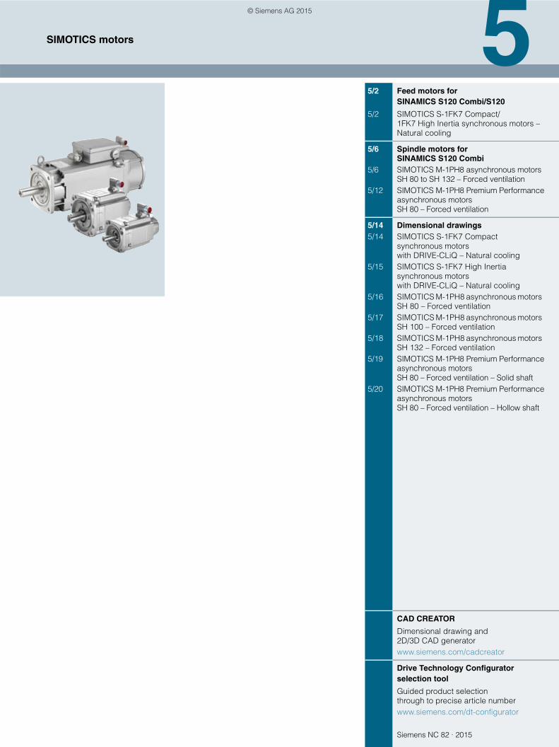
Siemens NC 82 · 2015
55/2 Feed motors for
SINAMICS S120 Combi/S120
5/2 SIMOTICS S-1FK7 Compact/1FK7 High Inertia synchronous motors – Natural cooling
5/6 Spindle motors for SINAMICS S120 Combi
5/6 SIMOTICS M-1PH8 asynchronous motors SH 80 to SH 132 – Forced ventilation
5/12 SIMOTICS M-1PH8 Premium Performance asynchronous motors SH 80 – Forced ventilation
5/14 Dimensional drawings5/14 SIMOTICS S-1FK7 Compact
synchronous motors with DRIVE-CLiQ – Natural cooling
5/15 SIMOTICS S-1FK7 High Inertia synchronous motors with DRIVE-CLiQ – Natural cooling
5/16 SIMOTICS M-1PH8 asynchronous motors SH 80 – Forced ventilation
5/17 SIMOTICS M-1PH8 asynchronous motors SH 100 – Forced ventilation
5/18 SIMOTICS M-1PH8 asynchronous motors SH 132 – Forced ventilation
5/19 SIMOTICS M-1PH8 Premium Performance asynchronous motors SH 80 – Forced ventilation – Solid shaft
5/20 SIMOTICS M-1PH8 Premium Performance asynchronous motors SH 80 – Forced ventilation – Hollow shaft
CAD CREATOR
Dimensional drawing and 2D/3D CAD generatorwww.siemens.com/cadcreator
Drive Technology Configurator selection tool
Guided product selection through to precise article numberwww.siemens.com/dt-configurator
SIMOTICS motors
© Siemens AG 2015
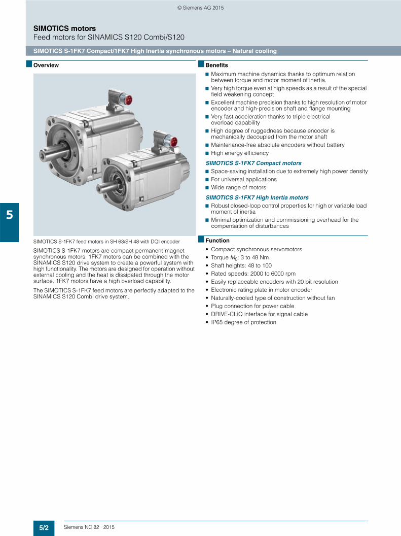
5/2 Siemens NC 82 · 2015
SIMOTICS motorsFeed motors for SINAMICS S120 Combi/S120
SIMOTICS S-1FK7 Compact/1FK7 High Inertia synchronous motors – Natural cooling
5
■ Overview
SIMOTICS S-1FK7 feed motors in SH 63/SH 48 with DQI encoder
SIMOTICS S-1FK7 motors are compact permanent-magnet synchronous motors. 1FK7 motors can be combined with the SINAMICS S120 drive system to create a powerful system with high functionality. The motors are designed for operation without external cooling and the heat is dissipated through the motor surface. 1FK7 motors have a high overload capability.
The SIMOTICS S-1FK7 feed motors are perfectly adapted to the SINAMICS S120 Combi drive system.
■ Benefits
7 Maximum machine dynamics thanks to optimum relation between torque and motor moment of inertia.
7 Very high torque even at high speeds as a result of the special field weakening concept
7 Excellent machine precision thanks to high resolution of motor encoder and high-precision shaft and flange mounting
7 Very fast acceleration thanks to triple electrical overload capability
7 High degree of ruggedness because encoder is mechanically decoupled from the motor shaft
7 Maintenance-free absolute encoders without battery7 High energy efficiency
SIMOTICS S-1FK7 Compact motors7 Space-saving installation due to extremely high power density7 For universal applications7 Wide range of motors
SIMOTICS S-1FK7 High Inertia motors7 Robust closed-loop control properties for high or variable load
moment of inertia7 Minimal optimization and commissioning overhead for the
compensation of disturbances
■ Function
• Compact synchronous servomotors• Torque M0: 3 to 48 Nm• Shaft heights: 48 to 100• Rated speeds: 2000 to 6000 rpm• Easily replaceable encoders with 20 bit resolution• Electronic rating plate in motor encoder• Naturally-cooled type of construction without fan• Plug connection for power cable• DRIVE-CLiQ interface for signal cable• IP65 degree of protection
© Siemens AG 2015
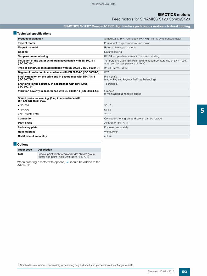
5/3Siemens NC 82 · 2015
SIMOTICS motorsFeed motors for SINAMICS S120 Combi/S120
SIMOTICS S-1FK7 Compact/1FK7 High Inertia synchronous motors – Natural cooling
5
■ Technical specifications
■ Options
When ordering a motor with options, -Z should be added to the Article No.
Product designation SIMOTICS S-1FK7 Compact/1FK7 High Inertia synchronous motor
Type of motor Permanent-magnet synchronous motor
Magnet material Rare-earth magnet material
Cooling Natural cooling
Temperature monitoring KTY84 temperature sensor in the stator winding
Insulation of the stator winding in accordance with EN 60034-1 (IEC 60034-1)
Temperature class 155 (F) for a winding temperature rise of ΔT = 100 K at an ambient temperature of 40 °C
Type of construction in accordance with EN 60034-7 (IEC 60034-7) IM B5 (IM V1, IM V3)
Degree of protection in accordance with EN 60034-5 (IEC 60034-5) IP65
Shaft extension on the drive end in accordance with DIN 748-3 (IEC 60072-1)
Plain shaft/feather key and keyway (half-key balancing)
Shaft and flange accuracy in accordance with DIN 42955 (IEC 60072-1)1)
Tolerance N
Vibration severity in accordance with EN 60034-14 (IEC 60034-14) Grade A is maintained up to rated speed
Sound pressure level LpA (1 m) in accordance with DIN EN ISO 1680, max.
• 1FK704 55 dB
• 1FK706 65 dB
• 1FK708/1FK710 70 dB
Connection Connectors for signals and power, can be rotated
Paint finish Anthracite RAL 7016
2nd rating plate Enclosed separately
Holding brake Without/with
Certificate of suitability cURus
Order code Description
K23 Special paint finish for "Worldwide" climate group: Primer and paint finish: Anthracite RAL 7016
1) Shaft extension run-out, concentricity of centering ring and shaft, and perpendicularity of flange to shaft.
© Siemens AG 2015

5/4 Siemens NC 82 · 2015
SIMOTICS motorsFeed motors for SINAMICS S120 Combi/S120
SIMOTICS S-1FK7 Compact/1FK7 High Inertia synchronous motors – Natural cooling
5
■ Selection and ordering data
Static torque Rated speed Shaft height Rated power SIMOTICS S-1FK7 synchronous motors Natural cooling
Moment of inertia of rotor Weight, approx.
Without brake
With brake
Without brake
With brake
M0 nrated SH Prated J J m mat atΔT=100 K ΔT=100 K
Nm rpm kW Article No. 10-4 kgm2 10-4 kgm2 kg kg
1FK7 Compact
6 3000 63 1.5 1FK7060-2AF71-1 7 7 1 7.7 8.7 7.1 8.5
8 3000 80 2.1 1FK7080-2AF71-1 7 7 1 14.2 17.5 10.3 13.3
8.5 3000 63 1.9 1FK7062-2AF71-1 7 7 1 11.2 12.2 9.1 10.5
11 2000 63 1.9 1FK7063-2AC71-1 7 7 1 14.7 15.7 11.1 12.5
3000 63 2.3 1FK7063-2AF71-1 7 7 1 14.7 15.7 11.1 12.5
12 2000 80 2.1 1FK7081-2AC71-1 7 7 1 20 23.5 12.9 15.9
3000 80 2.7 1FK7081-2AF71-1 7 7 1 20 23.5 12.9 15.9
16 2000 80 2.6 1FK7083-2AC71-1 7 7 1 26 29.5 15.6 18.6
3000 80 3.3 1FK7083-2AF71-1 7 7 1 26 29.5 15.6 18.6
18 2000 100 3.0 1FK7100-2AC71-1 7 7 1 54 62 17.6 21
3000 100 3.8 1FK7100-2AF71-1 7 7 1 54 62 17.6 21
20 2000 80 3.1 1FK7084-2AC71-1 7 7 1 32.5 35.5 18.3 21.3
3000 80 3.1 1FK7084-2AF71-1 7 7 1 32.5 35.5 18.3 21.3
27 2000 100 4.3 1FK7101-2AC71-1 7 7 1 79 87 23.0 27.5
36 2000 100 5.2 1FK7103-2AC71-1 7 7 1 104 112 28.5 33.0
48 2000 100 7.7 1FK7105-2AC71-1 7 7 1 154 162 39.0 43.5
1FK7 High Inertia
3 6000 48 0.9 1FK7042-3BK71-1 7 7 1 5.1 5.4 5.1 5.8
6 3000 63 1.5 1FK7060-3BF71-1 7 7 1 12.5 13.5 7.9 9.3
8.5 3000 63 1.9 1FK7062-3BF71-1 7 7 1 23.5 24.5 10.7 12.1
12 3000 80 2.7 1FK7081-3BF71-1 7 7 1 49 52 15.2 18.2
18 2000 100 3.0 1FK7100-3BC71-1 7 7 1 87 95 19.4 22.8
20 2000 80 3.1 1FK7084-3BC71-1 7 7 1 99 102 23.0 26.0
3000 80 3.1 1FK7084-3BF71-1 7 7 1 99 102 23.0 26.0
27 2000 100 4.3 1FK7101-3BC71-1 7 7 1 127 136 25.7 30.2
3000 100 4.9 1FK7101-3BF71-1 7 7 1 127 136 25.7 30.2
36 2000 100 5.2 1FK7103-3BC71-1 7 7 1 168 176 32.1 36.6
3000 100 4.4 1FK7103-3BF71-1 7 7 1 168 176 32.1 36.6
48 2000 100 7.7 1FK7105-3BC71-1 7 7 1 249 258 44.4 48.9
Encoder system for motors with DRIVE-CLiQ interface
20 bit absolute encoder single-turn (AS20DQI encoder) 20 bit absolute encoder single-turn +12 bit multi-turn (AM20DQI encoder)
QR
Shaft extension Shaft and flange accuracy
Holding brake
Feather key and keywayFeather key and keywayPlain shaftPlain shaft
Tolerance NTolerance NTolerance NTolerance N
WithoutWithWithoutWith
ABGH
© Siemens AG 2015
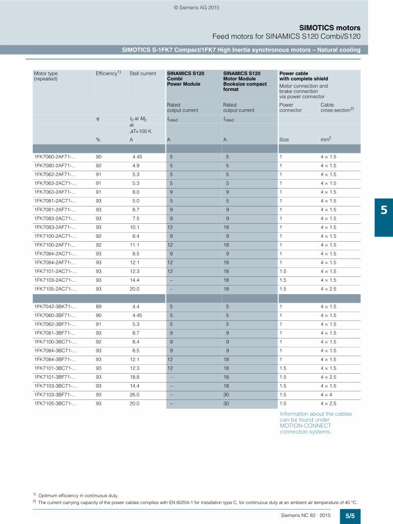
5/5Siemens NC 82 · 2015
SIMOTICS motorsFeed motors for SINAMICS S120 Combi/S120
SIMOTICS S-1FK7 Compact/1FK7 High Inertia synchronous motors – Natural cooling
5
Information about the cables can be found under MOTION-CONNECT connection systems.
Motor type(repeated)
Efficiency1) Stall current SINAMICS S120 Combi Power Module
SINAMICS S120 Motor Module Booksize compact format
Power cable with complete shieldMotor connection and brake connection via power connector
Rated output current
Rated output current
Power connector
Cablecross-section2)
η I0 at M0 Irated IratedatΔT=100 K
% A A A Size mm2
1FK7060-2AF71-... 90 4.45 5 5 1 4 × 1.5
1FK7080-2AF71-... 92 4.9 5 5 1 4 × 1.5
1FK7062-2AF71-... 91 5.3 5 5 1 4 × 1.5
1FK7063-2AC71-... 91 5.3 5 5 1 4 × 1.5
1FK7063-2AF71-... 91 8.0 9 9 1 4 × 1.5
1FK7081-2AC71-... 93 5.0 5 5 1 4 × 1.5
1FK7081-2AF71-... 93 8.7 9 9 1 4 × 1.5
1FK7083-2AC71-... 93 7.5 9 9 1 4 × 1.5
1FK7083-2AF71-... 93 10.1 12 18 1 4 × 1.5
1FK7100-2AC71-... 92 8.4 9 9 1 4 × 1.5
1FK7100-2AF71-... 92 11.1 12 18 1 4 × 1.5
1FK7084-2AC71-... 93 8.5 9 9 1 4 × 1.5
1FK7084-2AF71-... 93 12.1 12 18 1 4 × 1.5
1FK7101-2AC71-... 93 12.3 12 18 1.5 4 × 1.5
1FK7103-2AC71-... 93 14.4 – 18 1.5 4 × 1.5
1FK7105-2AC71-... 93 20.0 – 18 1.5 4 × 2.5
1FK7042-3BK71-... 89 4.4 5 5 1 4 × 1.5
1FK7060-3BF71-... 90 4.45 5 5 1 4 × 1.5
1FK7062-3BF71-... 91 5.3 5 5 1 4 × 1.5
1FK7081-3BF71-... 93 8.7 9 9 1 4 × 1.5
1FK7100-3BC71-... 92 8.4 9 9 1 4 × 1.5
1FK7084-3BC71-... 93 8.5 9 9 1 4 × 1.5
1FK7084-3BF71-... 93 12.1 12 18 1 4 × 1.5
1FK7101-3BC71-... 93 12.3 12 18 1.5 4 × 1.5
1FK7101-3BF71-... 93 18.8 – 18 1.5 4 × 2.5
1FK7103-3BC71-... 93 14.4 – 18 1.5 4 × 1.5
1FK7103-3BF71-... 93 26.0 – 30 1.5 4 × 4
1FK7105-3BC71-... 93 20.0 – 30 1.5 4 × 2.5
1) Optimum efficiency in continuous duty.2) The current carrying capacity of the power cables complies with EN 60204-1 for installation type C, for continuous duty at an ambient air temperature of 40 °C.
© Siemens AG 2015
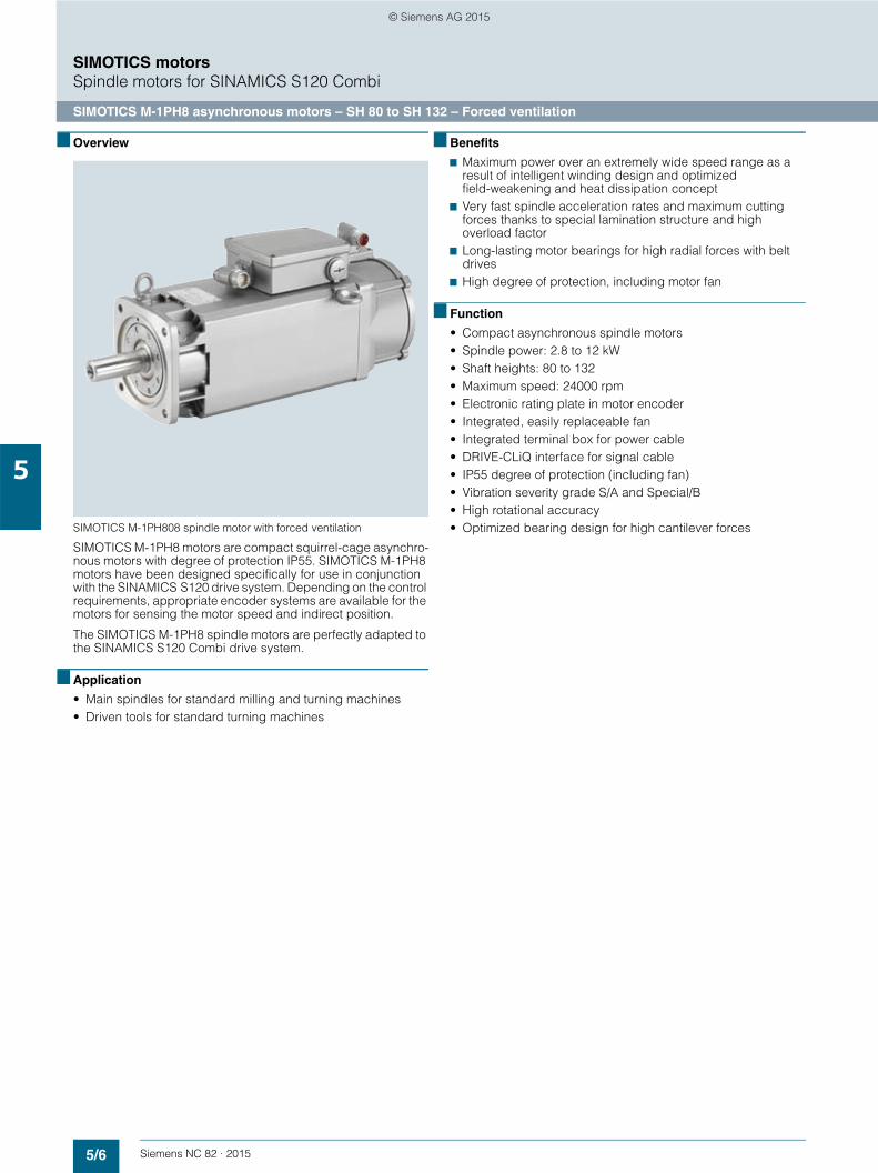
5/6 Siemens NC 82 · 2015
SIMOTICS motorsSpindle motors for SINAMICS S120 Combi
SIMOTICS M-1PH8 asynchronous motors – SH 80 to SH 132 – Forced ventilation
5
■ Overview
SIMOTICS M-1PH808 spindle motor with forced ventilation
SIMOTICS M-1PH8 motors are compact squirrel-cage asynchro-nous motors with degree of protection IP55. SIMOTICS M-1PH8 motors have been designed specifically for use in conjunction with the SINAMICS S120 drive system. Depending on the control requirements, appropriate encoder systems are available for the motors for sensing the motor speed and indirect position.
The SIMOTICS M-1PH8 spindle motors are perfectly adapted to the SINAMICS S120 Combi drive system.
■ Application
• Main spindles for standard milling and turning machines• Driven tools for standard turning machines
■ Benefits
7 Maximum power over an extremely wide speed range as a result of intelligent winding design and optimized field-weakening and heat dissipation concept
7 Very fast spindle acceleration rates and maximum cutting forces thanks to special lamination structure and high overload factor
7 Long-lasting motor bearings for high radial forces with belt drives
7 High degree of protection, including motor fan
■ Function
• Compact asynchronous spindle motors• Spindle power: 2.8 to 12 kW• Shaft heights: 80 to 132• Maximum speed: 24000 rpm• Electronic rating plate in motor encoder• Integrated, easily replaceable fan• Integrated terminal box for power cable• DRIVE-CLiQ interface for signal cable• IP55 degree of protection (including fan)• Vibration severity grade S/A and Special/B• High rotational accuracy• Optimized bearing design for high cantilever forces
© Siemens AG 2015

5/7Siemens NC 82 · 2015
SIMOTICS motorsSpindle motors for SINAMICS S120 Combi
SIMOTICS M-1PH8 asynchronous motors – SH 80 to SH 132 – Forced ventilation
5
■ Technical specifications
Terminal box assignment, max. connectable conductor cross-sections
Product designation SIMOTICS M-1PH8 motor
Cooling Forced ventilation
Ambient temperature, permissible -15 ... +40 °C
Temperature monitoring KTY84 temperature sensor in the stator winding
Insulation of the stator winding in accordance with EN 60034-1 (IEC 60034-1)
For an ambient temperature of up to 40 °C
• 1PH808/1PH810/1PH813 Temperature class 180 (H)
Motor fan ratings
• 1PH808 230 V 1 AC ± 10 %, 50 Hz265 V 1 AC ± 10 %, 60 Hz
• 1PH810/1PH813 400 V 3 AC ± 10 %, 50 Hz480 V 3 AC ± 10 %, 60 Hz
Encoder system, built-in DRIVE-CLiQ interface
• 1PH8...-1D... for speeds up to 12000 rpm 22 bit incremental encoder (resolution 4194304, internal 2048 S/R) + commutation position 11 bit (IC22DQ encoder)
• 1PH8...-1U... for speeds up to 15000 rpm 20 bit incremental encoder (resolution 1048576, internal 512 S/R) without commutation position (IN20DQ encoder)
• 1PH8...-1S... for speeds up to 24000 rpm 19 bit incremental encoder (resolution 524288, internal 256 S/R) without commutation position (IN19DQ encoder)
Sound pressure level LpA (1 m) in accordance with EN ISO 1680 Tolerance + 3 dB
Rated pulse frequency of 4 kHz and speed range up to 5000 rpm
• 1PH808/1PH810/1PH813 70 dB
Connection
• 1PH808/1PH810/1PH813 Terminal box top/cable entry from right/signal connection DE
• Fan
- 1PH808 Power connector
- 1PH810/1PH813 Terminals in terminal box
• Encoder system Connector for signals (without mating connector) or DRIVE-CLiQ
Vibration severity In accordance with Siemens/EN 60034-14 (IEC 60034-14)
Shaft and flange accuracy1) In accordance with Siemens/DIN 42955 (IEC 60072-1)
Degree of protection in accordance with EN 60034-5 (IEC 60034-5)
• 1PH808/1PH810/1PH813 IP55
• Fan IP55
Rating plate 1 unit attached to motor1 unit supplied loose in terminal box
Paint finish Anthracite RAL 7016
Certificate of suitability cURus
1PH8 motor Forced ventilation
Terminal box Cable entry Outer cable diameter, max.2)
Number of main terminals
Cross-section per terminal, max.
Rated current, max.3)
Type Type Power External signals
mm mm2 A
1PH808 gk803 1 × M25 × 1.5 1 × Ø 22 mm4) 20 Phases: 3 × M5Grounding: 2 × M5
1 × 10 50
1PH810 gk813 1 × M32 × 1.5 1 × Ø 22 mm4) 24.2 Phases: 3 × M5Grounding: 2 × M5
1 × 16 66
1PH810 Star/delta
gk826 1 × M32 × 1.5 1 × Ø 22 mm4) 24.2 Phases: 6 × M5Grounding: 2 × M5
1 × 10 50
1PH813 gk833 1 × M40 × 1.5 1 × Ø 22 mm4) 32 Phases: 3 × M6Grounding: 2 x M6
1 × 35 104
1) Shaft extension run-out, concentricity of centering ring and shaft, and perpendicularity of flange to shaft.2) Dependent on the design of the metric cable gland.3) Current-carrying capacity based on EN 60204-1 and IEC 60364-5-52 according to installation type C.4) Hole with Ø 22 mm, 90° to signal connection.
© Siemens AG 2015
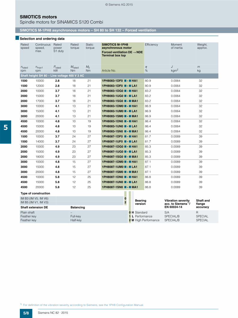
5/8 Siemens NC 82 · 2015
SIMOTICS motorsSpindle motors for SINAMICS S120 Combi
SIMOTICS M-1PH8 asynchronous motors – SH 80 to SH 132 – Forced ventilation
5
■ Selection and ordering data
Rated speed
Continuousspeed, max.
Ratedpower S1 duty
Rated torque
Static torque
SIMOTICS M-1PH8 asynchronous motorForced ventilation DE → NDE Terminal box top
Efficiency Moment of inertia
Weight, approx.
nrated nmax1 Prated Mrated M0 η J mrpm rpm kW Nm Nm Article No. % kgm2 kg
Shaft height SH 80 – Line voltage 400 V 3 AC
1500 10000 2.8 18 21 1PH8083-1DF0 7 - 7 HA1 80.9 0.0064 32
1500 12000 2.8 18 21 1PH8083-1DF0 7 - 7 LA1 80.9 0.0064 32
2000 10000 3.7 18 21 1PH8083-1DG0 7 - 7 HA1 83.2 0.0064 32
2000 15000 3.7 18 21 1PH8083-1UG0 7 - 7 LA1 83.2 0.0064 32
2000 17000 3.7 18 21 1PH8083-1SG0 7 - 7 MA1 83.2 0.0064 32
3000 10000 4.1 13 21 1PH8083-1DM0 7 - 7 HA1 86.9 0.0064 32
3000 15000 4.1 13 21 1PH8083-1UM0 7 - 7 LA1 86.9 0.0064 32
3000 20000 4.1 13 21 1PH8083-1SM0 7 - 7 MA1 86.9 0.0064 32
4500 10000 4.8 10 19 1PH8083-1DN0 7 - 7 HA1 86.4 0.0064 32
4500 15000 4.8 10 19 1PH8083-1UN0 7 - 7 LA1 86.4 0.0064 32
4500 20000 4.8 10 19 1PH8083-1SN0 7 - 7 MA1 86.4 0.0064 32
1500 10000 3.7 24 27 1PH8087-1DF0 7 - 7 HA1 81.7 0.0089 39
1500 14000 3.7 24 27 1PH8087-1UF0 7 - 7 LA1 81.7 0.0089 39
2000 10000 4.9 23 27 1PH8087-1DG0 7 - 7 HA1 85.3 0.0089 39
2000 15000 4.9 23 27 1PH8087-1UG0 7 - 7 LA1 85.3 0.0089 39
2000 18000 4.9 23 27 1PH8087-1SG0 7 - 7 MA1 85.3 0.0089 39
3000 10000 4.8 15 27 1PH8087-1DM0 7 - 7 HA1 87.1 0.0089 39
3000 15000 4.8 15 27 1PH8087-1UM0 7 - 7 LA1 87.1 0.0089 39
3000 20000 4.8 15 27 1PH8087-1SM0 7 - 7 MA1 87.1 0.0089 39
4500 10000 5.8 12 25 1PH8087-1DN0 7 - 7 HA1 86.8 0.0089 39
4500 15000 5.8 12 25 1PH8087-1UN0 7 - 7 LA1 86.8 0.0089 39
4500 20000 5.8 12 25 1PH8087-1SN0 7 - 7 MA1 86.8 0.0089 39
Type of construction
Bearing version
Vibration severity acc. to Siemens1)/EN 60034-14
Shaft and flange accuracy
IM B3 (IM V5, IM V6) 0IM B5 (IM V1, IM V3) 2
Shaft extension DE Balancing
Plain shaft – 0 H Standard S/A RFeather key Full-key 1 L Performance SPECIAL/B SPECIALFeather key Half-key 2 M High Performance SPECIAL/B SPECIAL
1) For definition of the vibration severity according to Siemens, see the 1PH8 Configuration Manual.
© Siemens AG 2015

5/9Siemens NC 82 · 2015
SIMOTICS motorsSpindle motors for SINAMICS S120 Combi
SIMOTICS M-1PH8 asynchronous motors – SH 80 to SH 132 – Forced ventilation
5
✓ Perfectly suited as main spindleG Suitable as main spindle! Perfectly suited as driven tool– Not suitable
■ Options
When ordering a motor with options, -Z should be added to the Article No.
Motor type(repeated)
Rated current for S1 duty
Stall current
SINAMICS S120 Combi
Rated output current for S1 duty
3-axis Power Modules 4-axis Power Modules
Article No. Article No.
Irated I0 Irated 6SL3111- 6SL3111- 6SL3111- 6SL3111- 6SL3111- 6SL3111-A A A 3VE21-6FA0 3VE21-6EA0 3VE22-0HA0 4VE21-6FA0 4VE21-6EA0 4VE22-0HA0
1PH8083-1.F... 7.5 8 9 G G/! G/! G/! G/! G/!
1PH8083-1.F... 7.5 8 9 G G/! G/! G/! G/! G/!
1PH8083-1.G... 11.6 12 12 G G G G G G/!
1PH8083-1.G... 11.6 12 12 G G G G G G/!
1PH8083-1.G... 11.6 12 12 G G G G G G/!
1PH8083-1.M... 13.6 17 18 G G G G G G/!2)
1PH8083-1.M... 13.6 17 18 G G G G G G/!2)
1PH8083-1.M... 13.6 17 18 G G G G G G/!2)
1PH8083-1.N... 17 23 18 ✓ G G ✓ G G
1PH8083-1.N... 17 23 18 ✓ G G ✓ G G
1PH8083-1.N... 17 23 18 ✓ G G ✓ G G
1PH8087-1.F... 10 11 12 G G/!2)G/!2)
G/!2)G/!2)
G/!
1PH8087-1.F... 10 11 12 G G/!2)G/!2)
G/!2)G/!2)
G/!
1PH8087-1.G... 14.1 15 18 G G G G G G
1PH8087-1.G... 14.1 15 18 G G G G G G
1PH8087-1.G... 14.1 15 18 G G G G G G
1PH8087-1.M... 17.3 23 18 ✓ G G ✓ G G
1PH8087-1.M... 17.3 23 18 ✓ G G ✓ G G
1PH8087-1.M... 17.3 23 18 ✓ G G ✓ G G
1PH8087-1.N... 19.5 28 30 ✓2)G G ✓2)
G G
1PH8087-1.N... 19.5 28 30 ✓2)G G ✓2)
G G
1PH8087-1.N... 19.5 28 30 ✓2)G G ✓2)
G G
Order code Description
K23 Special paint finish for "Worldwide" climate group: Primer and paint finish: Anthracite RAL 7016
2) With derating.
© Siemens AG 2015
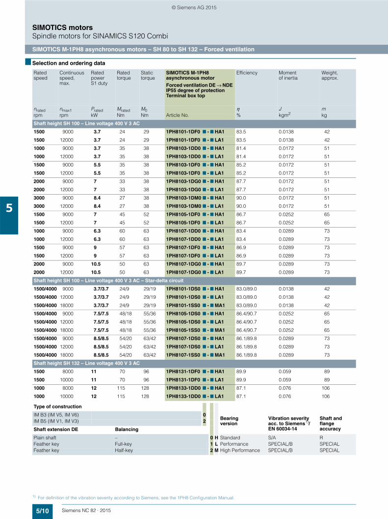
5/10 Siemens NC 82 · 2015
SIMOTICS motorsSpindle motors for SINAMICS S120 Combi
SIMOTICS M-1PH8 asynchronous motors – SH 80 to SH 132 – Forced ventilation
5
■ Selection and ordering data
Rated speed
Continuousspeed, max.
Ratedpower S1 duty
Rated torque
Static torque
SIMOTICS M-1PH8 asynchronous motorForced ventilation DE → NDE IP55 degree of protectionTerminal box top
Efficiency Moment of inertia
Weight, approx.
nrated nmax1 Prated Mrated M0 η J mrpm rpm kW Nm Nm Article No. % kgm2 kg
Shaft height SH 100 – Line voltage 400 V 3 AC
1500 9000 3.7 24 29 1PH8101-1DF0 7 - 7 HA1 83.5 0.0138 42
1500 12000 3.7 24 29 1PH8101-1DF0 7 - 7 LA1 83.5 0.0138 42
1000 9000 3.7 35 38 1PH8103-1DD0 7 - 7 HA1 81.4 0.0172 51
1000 12000 3.7 35 38 1PH8103-1DD0 7 - 7 LA1 81.4 0.0172 51
1500 9000 5.5 35 38 1PH8103-1DF0 7 - 7 HA1 85.2 0.0172 51
1500 12000 5.5 35 38 1PH8103-1DF0 7 - 7 LA1 85.2 0.0172 51
2000 9000 7 33 38 1PH8103-1DG0 7 - 7 HA1 87.7 0.0172 51
2000 12000 7 33 38 1PH8103-1DG0 7 - 7 LA1 87.7 0.0172 51
3000 9000 8.4 27 38 1PH8103-1DM0 7 - 7 HA1 90.0 0.0172 51
3000 12000 8.4 27 38 1PH8103-1DM0 7 - 7 LA1 90.0 0.0172 51
1500 9000 7 45 52 1PH8105-1DF0 7 - 7 HA1 86.7 0.0252 65
1500 12000 7 45 52 1PH8105-1DF0 7 - 7 LA1 86.7 0.0252 65
1000 9000 6.3 60 63 1PH8107-1DD0 7 - 7 HA1 83.4 0.0289 73
1000 12000 6.3 60 63 1PH8107-1DD0 7 - 7 LA1 83.4 0.0289 73
1500 9000 9 57 63 1PH8107-1DF0 7 - 7 HA1 86.9 0.0289 73
1500 12000 9 57 63 1PH8107-1DF0 7 - 7 LA1 86.9 0.0289 73
2000 9000 10.5 50 63 1PH8107-1DG0 7 - 7 HA1 89.7 0.0289 73
2000 12000 10.5 50 63 1PH8107-1DG0 7 - 7 LA1 89.7 0.0289 73
Shaft height SH 100 – Line voltage 400 V 3 AC – Star-delta circuit
1500/4000 9000 3.7/3.7 24/9 29/19 1PH8101-1DS0 7 - 7 HA1 83.0/89.0 0.0138 42
1500/4000 12000 3.7/3.7 24/9 29/19 1PH8101-1DS0 7 - 7 LA1 83.0/89.0 0.0138 42
1500/4000 18000 3.7/3.7 24/9 29/19 1PH8101-1SS0 7 - 7 MA1 83.0/89.0 0.0138 42
1500/4000 9000 7.5/7.5 48/18 55/36 1PH8105-1DS0 7 - 7 HA1 86.4/90.7 0.0252 65
1500/4000 12000 7.5/7.5 48/18 55/36 1PH8105-1DS0 7 - 7 LA1 86.4/90.7 0.0252 65
1500/4000 18000 7.5/7.5 48/18 55/36 1PH8105-1SS0 7 - 7 MA1 86.4/90.7 0.0252 65
1500/4000 9000 8.5/8.5 54/20 63/42 1PH8107-1DS0 7 - 7 HA1 86.1/89.8 0.0289 73
1500/4000 12000 8.5/8.5 54/20 63/42 1PH8107-1DS0 7 - 7 LA1 86.1/89.8 0.0289 73
1500/4000 18000 8.5/8.5 54/20 63/42 1PH8107-1SS0 7 - 7 MA1 86.1/89.8 0.0289 73
Shaft height SH 132 – Line voltage 400 V 3 AC
1500 8000 11 70 96 1PH8131-1DF0 7 - 7 HA1 89.9 0.059 89
1500 10000 11 70 96 1PH8131-1DF0 7 - 7 LA1 89.9 0.059 89
1000 8000 12 115 128 1PH8133-1DD0 7 - 7 HA1 87.1 0.076 106
1000 10000 12 115 128 1PH8133-1DD0 7 - 7 LA1 87.1 0.076 106
Type of construction
Bearing version
Vibration severity acc. to Siemens1)/EN 60034-14
Shaft and flange accuracy
IM B3 (IM V5, IM V6) 0IM B5 (IM V1, IM V3) 2
Shaft extension DE Balancing
Plain shaft – 0 H Standard S/A RFeather key Full-key 1 L Performance SPECIAL/B SPECIALFeather key Half-key 2 M High Performance SPECIAL/B SPECIAL
1) For definition of the vibration severity according to Siemens, see the 1PH8 Configuration Manual.
© Siemens AG 2015
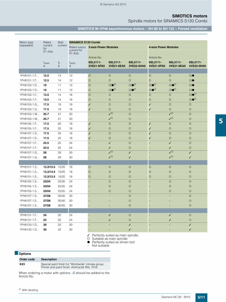
5/11Siemens NC 82 · 2015
SIMOTICS motorsSpindle motors for SINAMICS S120 Combi
SIMOTICS M-1PH8 asynchronous motors – SH 80 to SH 132 – Forced ventilation
5
✓ Perfectly suited as main spindleG Suitable as main spindle! Perfectly suited as driven tool– Not suitable
■ Options
When ordering a motor with options, -Z should be added to the Article No.
Motor type(repeated)
Rated current for S1 duty
Stall current
SINAMICS S120 Combi
Rated output current for S1 duty
3-axis Power Modules 4-axis Power Modules
Article No. Article No.
Irated I0 Irated 6SL3111- 6SL3111- 6SL3111- 6SL3111- 6SL3111- 6SL3111-A A A 3VE21-6FA0 3VE21-6EA0 3VE22-0HA0 4VE21-6FA0 4VE21-6EA0 4VE22-0HA0
1PH8101-1.F... 12.5 14 12 G G G G G G/!
1PH8101-1.F... 12.5 14 12 G G G G G G/!
1PH8103-1.D... 10 11 12 G G/!2)G/!2)
G/!2)G/!2)
G/!
1PH8103-1.D... 10 11 12 G G/!2)G/!2)
G/!2)G/!2)
G/!
1PH8103-1.F... 13.5 14 18 G G G G G G/!2)
1PH8103-1.F... 13.5 14 18 G G G G G G/!2)
1PH8103-1.G... 17.5 19 18 ✓ G G ✓ G G
1PH8103-1.G... 17.5 19 18 ✓ G G ✓ G G
1PH8103-1.M... 25.7 31 30 – ✓2)G – ✓2)
G
1PH8103-1.M... 25.7 31 30 – ✓2)G – ✓2)
G
1PH8105-1.F... 17.5 20 18 ✓ G G ✓ G G
1PH8105-1.F... 17.5 20 18 ✓ G G ✓ G G
1PH8107-1.D... 17.5 25 18 ✓ G G ✓ G G
1PH8107-1.D... 17.5 25 18 ✓ G G ✓ G G
1PH8107-1.F... 23.5 25 24 – ✓ G – ✓ G
1PH8107-1.F... 23.5 25 24 – ✓ G – ✓ G
1PH8107-1.G... 26 29 30 – ✓2) ✓ – ✓2) ✓
1PH8107-1.G... 26 29 30 – ✓2) ✓ – ✓2) ✓
1PH8101-1.S... 13.2/13.5 15/20 18 G G G G G G
1PH8101-1.S... 13.2/13.5 15/20 18 G G G G G G
1PH8101-1.S... 13.2/13.5 15/20 18 G G G G G G
1PH8105-1.S... 23/24 25/35 24 – G G – G G
1PH8105-1.S... 23/24 25/35 24 – G G – G G
1PH8105-1.S... 23/24 25/35 24 – G G – G G
1PH8107-1.S... 27/28 30/40 30 – – G – – G
1PH8107-1.S... 27/28 30/40 30 – – G – – G
1PH8107-1.S... 27/28 30/40 30 – – G – – G
1PH8131-1.F... 24 30 24 – ✓ G – ✓ G
1PH8131-1.F... 24 30 24 – ✓ G – ✓ G
1PH8133-1.D... 30 32 30 – – ✓ – – ✓
1PH8133-1.D... 30 32 30 – – ✓ – – ✓
Order code Description
K23 Special paint finish for "Worldwide" climate group: Primer and paint finish: Anthracite RAL 7016
2) With derating.
© Siemens AG 2015

5/12 Siemens NC 82 · 2015
SIMOTICS motorsSpindle motors for SINAMICS S120 Combi
SIMOTICS M-1PH8 Premium Performance asynchronous motors – SH 80 – Forced ventilation
5
■ Selection and ordering data
Rated speed
Maximum speed
Ratedpower S1 duty
Rated torque
SIMOTICS M-1PH8 Premium Performance asynchronous motorForced ventilation DE → NDE IP55 degree of protectionTerminal box top
Efficiency Moment of inertia
Weight, approx.Motor with solid shaft
nrated nmax Prated Mrated η J mrpm rpm kW Nm Article No. % kgm2 kg
Shaft height SH 80 – Line voltage 400 V 3 AC
9000 24000 2.8 3.0 1PH8081-1SU0 2-7NA1-Z Q12+Q52 88.5 0.0045 24
9000 24000 2.8 3.0 1PH8081-1SW02-7NA1-Z Q12+Q52 84.3 0.0045 24
9000 24000 3.5 3.7 1PH8081-1SV0 2-7NA1-Z Q12+Q52 95.0 0.0045 24
5200 24000 4.5 8.3 1PH8083-1SW02-7NA1-Z Q12+Q52 86.6 0.0064 29.5
12000 24000 4.5 3.6 1PH8083-1SV0 2-7NA1-Z Q12+Q52 93.9 0.0064 29.5
12000 24000 6.5 5.2 1PH8087-1SV0 2-7NA1-Z Q12+Q52 94.7 0.0089 37
Type of construction Q52 DE flange with additional 4 × M8 thread for one adapter plate for alignment of motor shaft with spindle shaftIM B5 (IM V1, IM V3) 2
Shaft extension DE
Solid shaft 0 Q12 M5 sealing air connection on terminal box1)
Hollow shaft Order code Y64 required. Prepared for rotary union without bearing1)
3
Bearing version
Vibration severity acc. to Siemens2) EN 60034-14
Shaft and flange accuracy
Premium Performance
SPECIAL/B SPECIAL N
1) For further details on interfaces and sealing air conditioning, see the 1PH8 Configuration Manual.2) For definition of the vibration severity according to Siemens, see the 1PH8 Configuration Manual.
© Siemens AG 2015
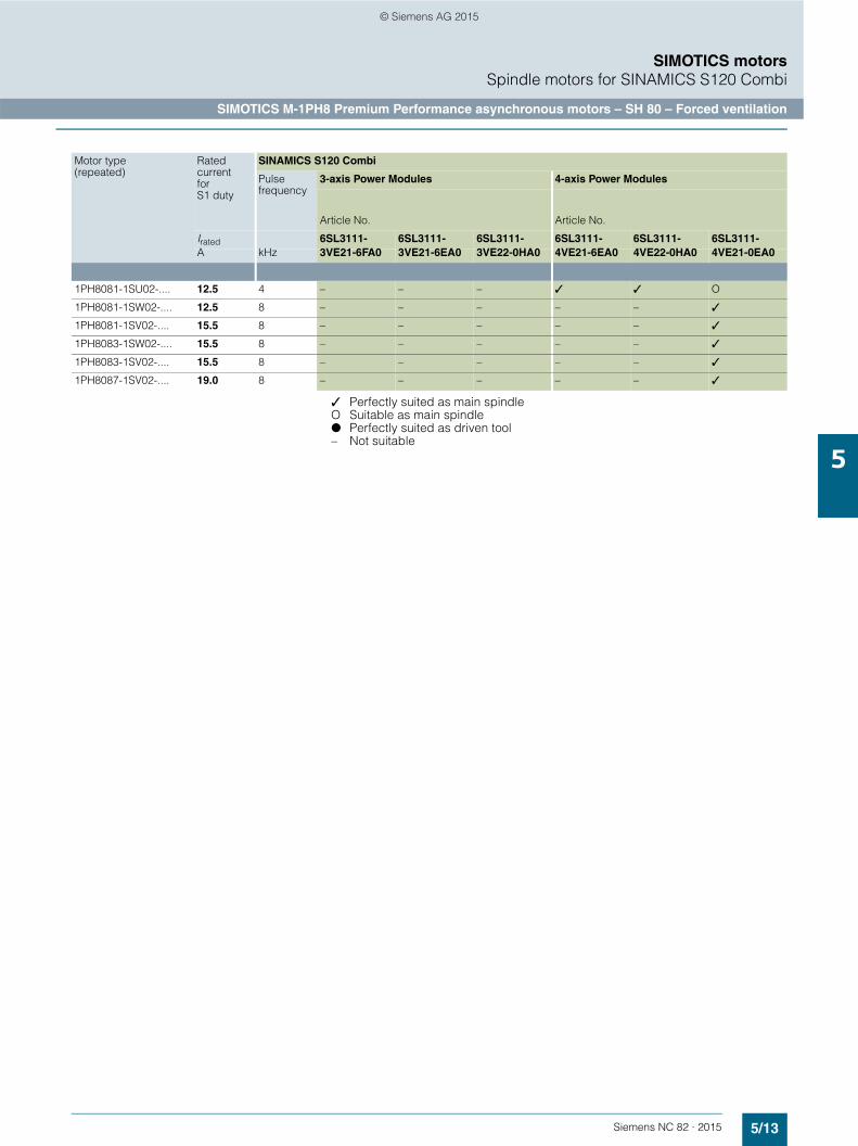
5/13Siemens NC 82 · 2015
SIMOTICS motorsSpindle motors for SINAMICS S120 Combi
SIMOTICS M-1PH8 Premium Performance asynchronous motors – SH 80 – Forced ventilation
5
✓ Perfectly suited as main spindleG Suitable as main spindle! Perfectly suited as driven tool– Not suitable
Motor type(repeated)
Rated current for S1 duty
SINAMICS S120 Combi
Pulse frequency
3-axis Power Modules 4-axis Power Modules
Article No. Article No.
Irated 6SL3111- 6SL3111- 6SL3111- 6SL3111- 6SL3111- 6SL3111-A kHz 3VE21-6FA0 3VE21-6EA0 3VE22-0HA0 4VE21-6EA0 4VE22-0HA0 4VE21-0EA0
1PH8081-1SU02-.... 12.5 4 – – – ✓ ✓ G
1PH8081-1SW02-.... 12.5 8 – – – – – ✓
1PH8081-1SV02-.... 15.5 8 – – – – – ✓
1PH8083-1SW02-.... 15.5 8 – – – – – ✓
1PH8083-1SV02-.... 15.5 8 – – – – – ✓
1PH8087-1SV02-.... 19.0 8 – – – – – ✓
© Siemens AG 2015

5/14 Siemens NC 82 · 2015
SIMOTICS motorsDimensional drawings
SIMOTICS S-1FK7 Compact synchronous motors with DRIVE-CLiQ – Natural cooling
5
■ Dimensional drawings
For motor Dimensions in mm (inches)
Shaft extension DE
Shaft height
Type DIN IEC
a1P
b1N
c1LA
e1M
f AB
f1T
i2–
s2S
dD
d6–
l E
t GA
u F
1FK7 Compact, natural cooling, DQI encoder with DRIVE-CLiQ, with/without brake
63 1FK706.-2A 155 110 10 130 126 3.5 50 9 24 M8 50 27 8(6.10) (4.33) (0.39) (5.12) (4.96) (0.14) (1.97) (0.35) (0.94) (1.97) (1.06) (0.31)
80 1FK708.-2A 194 130 11.5 165 155 3.5 58 11 32 M12 58 35 10(7.64) (5.12) (0.45) (6.50) (6.10) (0.14) (2.28) (0.43) (1.26) (2.28) (1.38) (0.39)
100 1FK710.-2A 245 180 13 215 192 4 80 14 38 M12 80 41 10(9.65) (7.09) (0.51) (8.46) (7.56) (0.16) (3.15) (0.55) (1.50) (3.15) (1.61) (0.39)
DQI encoder with DRIVE-CLiQ
Without brake With brake
Shaft height
Type DIN IEC
o2–
kLB
o1–
kLB
o1–
g1–
g2–
63 1FK7060-2A 50 168 106 203 141 104.5 104(1.97) (6.61) (4.17) (7.99) (5.55) (4.11) (4.09)
1FK7062-2A 50 190 128 226 163 104.5 104(1.97) (7.48) (5.04) (8.90) (6.42) (4.11) (4.09)
1FK7063-2A 50 213 151 248 186 104.5 104(1.97) (8.39) (5.94) (9.76) (7.32) (4.11) (4.09)
80 1FK7080-2A 48 171 111 223 163 104.5 119(1.89) (6.73) (4.37) (8.78) (6.42) (4.11) (4.69)
1FK7081-2A 48 190 130 242 182 104.5 119(1.89) (7.48) (5.12) (9.53) (7.17) (4.11) (4.69)
1FK7083-2A 48 209 149 261 201 104.5 119(1.89) (8.23) (5.87) (10.28) (7.91) (4.11) (4.69)
1FK7084-2A 48 229 168 281 221 104.5 119(1.89) (9.02) (6.61) (11.06) (8.70) (4.11) (4.69)
100 1FK7100-2A 53 183 118 220 170 104.5 137(2.09) (7.20) (4.65) (8.66) (6.69) (4.11) (5.39)
1FK7101-2A 53 209 144 261 196 104.5 158(2.09) (8.23) (5.67) (10.28) (7.72) (4.11) (6.22)
1FK7103-2A 53 235 170 287 222 104.5 158(2.09) (9.25) (6.69) (11.30) (8.74) (4.11) (6.22)
1FK7105-2A 53 287 222 339 274 104.5 158(2.09) (11.30) (8.74) (13.35) (10.79) (4.11) (6.22)
G_N
C01
_XX
_004
39a
u
t
s2
fa1
e1
k
o1c1i2
l
o2
g 1
g 2
Ød
Øb 1
d6 f1
1FK7061FK7081FK710
© Siemens AG 2015
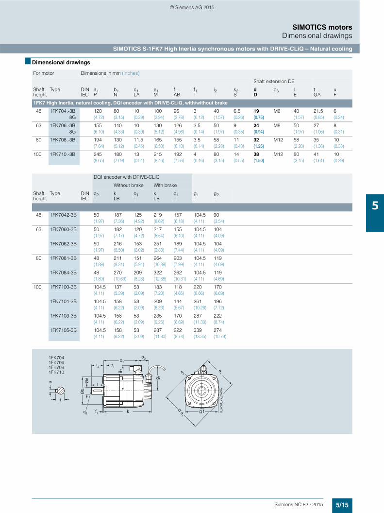
5/15Siemens NC 82 · 2015
SIMOTICS motorsDimensional drawings
SIMOTICS S-1FK7 High Inertia synchronous motors with DRIVE-CLiQ – Natural cooling
5
■ Dimensional drawings
For motor Dimensions in mm (inches)
Shaft extension DE
Shaft height
Type DIN IEC
a1P
b1N
c1LA
e1M
f AB
f1T
i2–
s2S
d D
d6–
l E
t GA
u F
1FK7 High Inertia, natural cooling, DQI encoder with DRIVE-CLiQ, with/without brake
48 1FK704.-3B 120 80 10 100 96 3 40 6.5 19 M6 40 21.5 68G (4.72) (3.15) (0.39) (3.94) (3.78) (0.12) (1.57) (0.26) (0.75) (1.57) (0.85) (0.24)
63 1FK706.-3B 155 110 10 130 126 3.5 50 9 24 M8 50 27 88G (6.10) (4.33) (0.39) (5.12) (4.96) (0.14) (1.97) (0.35) (0.94) (1.97) (1.06) (0.31)
80 1FK708.-3B 194 130 11.5 165 155 3.5 58 11 32 M12 58 35 10(7.64) (5.12) (0.45) (6.50) (6.10) (0.14) (2.28) (0.43) (1.26) (2.28) (1.38) (0.38)
100 1FK710.-3B 245 180 13 215 192 4 80 14 38 M12 80 41 10(9.65) (7.09) (0.51) (8.46) (7.56) (0.16) (3.15) (0.55) (1.50) (3.15) (1.61) (0.39)
DQI encoder with DRIVE-CLiQ
Without brake With brake
Shaft height
Type DIN IEC
o2–
kLB
o1–
k LB
o1–
g1–
g2–
48 1FK7042-3B 50 187 125 219 157 104.5 90(1.97) (7.36) (4.92) (8.62) (6.18) (4.11) (3.54)
63 1FK7060-3B 50 182 120 217 155 104.5 104(1.97) (7.17) (4.72) (8.54) (6.10) (4.11) (4.09)
1FK7062-3B 50 216 153 251 189 104.5 104(1.97) (8.50) (6.02) (9.88) (7.44) (4.11) (4.09)
80 1FK7081-3B 48 211 151 264 203 104.5 119(1.89) (8.31) (5.94) (10.39) (7.99) (4.11) (4.69)
1FK7084-3B 48 270 209 322 262 104.5 119(1.89) (10.63) (8.23) (12.68) (10.31) (4.11) (4.69)
100 1FK7100-3B 104.5 137 53 183 118 220 170(4.11) (5.39) (2.09) (7.20) (4.65) (8.66) (6.69)
1FK7101-3B 104.5 158 53 209 144 261 196(4.11) (6.22) (2.09) (8.23) (5.67) (10.28) (7.72)
1FK7103-3B 104.5 158 53 235 170 287 222(4.11) (6.22) (2.09) (9.25) (6.69) (11.30) (8.74)
1FK7105-3B 104.5 158 53 287 222 339 274(4.11) (6.22) (2.09) (11.30) (8.74) (13.35) (10.79)
G_N
C01
_XX
_004
39a
u
t
s2
fa1
e1
k
o1c1i2
l
o2
g 1
g 2
Ød
Øb 1
d6 f1
1FK7041FK7061FK708 1FK710
© Siemens AG 2015

5/16 Siemens NC 82 · 2015
SIMOTICS motorsDimensional drawings
SIMOTICS M-1PH8 asynchronous motors – SH 80 – Forced ventilation
5
■ Dimensional drawings
For motor Dimensions in mm (inches)
Shaft extension DE
Shaft height
Type IEC A AB B C H HA HD L LB K D DB E F GA
1PH8, type of construction IM B3, forced ventilation
80 1PH8083 125 155 194 38 80 8 216 455 375 10 32 M12 80 10 35(4.92) (6.10) (7.64) (1.50) (3.15) (0.31) (8.50) (17.91) (14.76) (0.39) (1.26) (3.15) (0.39) (1.38)
1PH8087 244 505 425(9.61) (19.88) (16.73)
G_P
M21
_EN
_000
01d
Connector size 1 for fan connection
CØK
ØD
BL
GA
F
HA
A
LB
HD
HDB
AB
E
1PH808
For motor Dimensions in mm (inches)
Shaft extension DE
Shaft height
Type IEC AB H HD L LA LB M N P S T D DB E F GA
1PH8, type of construction IM B5, forced ventilation
80 1PH8083 155 77.5 213.5 455 12 375 165 130 200 12 3.5 32 M12 80 10 35(6.10) (3.05) (8.41) (17.91) (0.47) (14.76) (6.50) (5.12) (7.87) (0.47) (0.14) (1.26) (3.15) (0.39) (1.38)
1PH8087 505 425(19.88) (16.73)
G_P
M21
_EN
_000
02d
Connector size 1 for fan connection
GA
F
LA
ØD
ØN
TE
L
ØS
P
M
LB
HD
HDB
AB
1PH808
© Siemens AG 2015
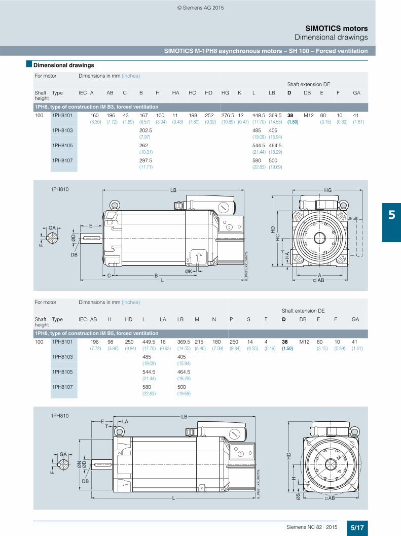
5/17Siemens NC 82 · 2015
SIMOTICS motorsDimensional drawings
SIMOTICS M-1PH8 asynchronous motors – SH 100 – Forced ventilation
5
■ Dimensional drawings
For motor Dimensions in mm (inches)
Shaft extension DE
Shaft height
Type IEC A AB C B H HA HC HD HG K L LB D DB E F GA
1PH8, type of construction IM B3, forced ventilation
100 1PH8101 160 196 43 167 100 11 198 252 276.5 12 449.5 369.5 38 M12 80 10 41(6.30) (7.72) (1.69) (6.57) (3.94) (0.43) (7.80) (9.92) (10.89) (0.47) (17.70) (14.55) (1.50) (3.15) (0.39) (1.61)
1PH8103 202.5 485 405(7.97) (19.09) (15.94)
1PH8105 262 544.5 464.5(10.31) (21.44) (18.29)
1PH8107 297.5 580 500(11.71) (22.83) (19.69)
G_P
M21
_XX
_000
67b
BL
GA
F
HA
A
LB
HC
HG
HD
HDB
CAB
E
ØD
ØK
1PH810
For motor Dimensions in mm (inches)
Shaft extension DE
Shaft height
Type IEC AB H HD L LA LB M N P S T D DB E F GA
1PH8, type of construction IM B5, forced ventilation
100 1PH8101 196 98 250 449.5 16 369.5 215 180 250 14 4 38 M12 80 10 41(7.72) (3.86) (9.84) (17.70) (0.63) (14.55) (8.46) (7.09) (9.84) (0.55) (0.16) (1.50) (3.15) (0.39) (1.61)
1PH8103 485 405(19.09) (15.94)
1PH8105 544.5 464.5(21.44) (18.29)
1PH8107 580 500(22.83) (19.69)
ØD
ØN
G_P
M21
_XX
_000
77a
GA
F
T
LB
L
LAE
HD
HDB
AB
P
M
ØS
1PH810
© Siemens AG 2015

5/18 Siemens NC 82 · 2015
SIMOTICS motorsDimensional drawings
SIMOTICS M-1PH8 asynchronous motors – SH 132 – Forced ventilation
5
■ Dimensional drawings
For motor Dimensions in mm (inches)
Shaft extension DE
Shaft height
Type IEC A AB B C H HA HC HD HG K L LB D DB E F GA
1PH8, type of construction IM B3, forced ventilation
132 1PH8131 216 260 220.5 53 132 15 262 317.5 357.5 12 549 439 48 M16 110 14 51.5(8.50) (10.24) (8.68) (2.09) (5.20) (0.59) (10.31) (12.50) (14.07) (0.47) (21.61) (17.28) (1.89) (4.33) (0.55) (2.03)
1PH8133 265.5 594 484(10.45) (23.39) (19.06)
G_P
M21
_XX
_000
05c
B
GA
F
HA
A
LB
HC
HG
HD
HDB
CAB
E
ØD
ØK
L
1PH813
For motor Dimensions in mm (inches)
Shaft extension DE
Shaft height
Type IEC AB H HD L LA LB M N P S T D DB E F GA
1PH8, type of construction IM B5, forced ventilation
132 1PH8131 260 130 315.5 549 18 439 300 250 340 18 5 48 M16 110 14 51.5(10.24) (5.12) (12.42) (21.61) (0.71) (17.28) (11.81) (9.84) (13.39) (0.71) (0.20) (1.89) (4.33) (0.55) (2.03)
1PH8133 594 484(23.39) (19.06)
ØD
ØN
ØS
G_P
M21
_XX
_000
76a
GA
F
E
P
LB
L
HD
H
LA
T
DB
M
AB
1PH813
© Siemens AG 2015
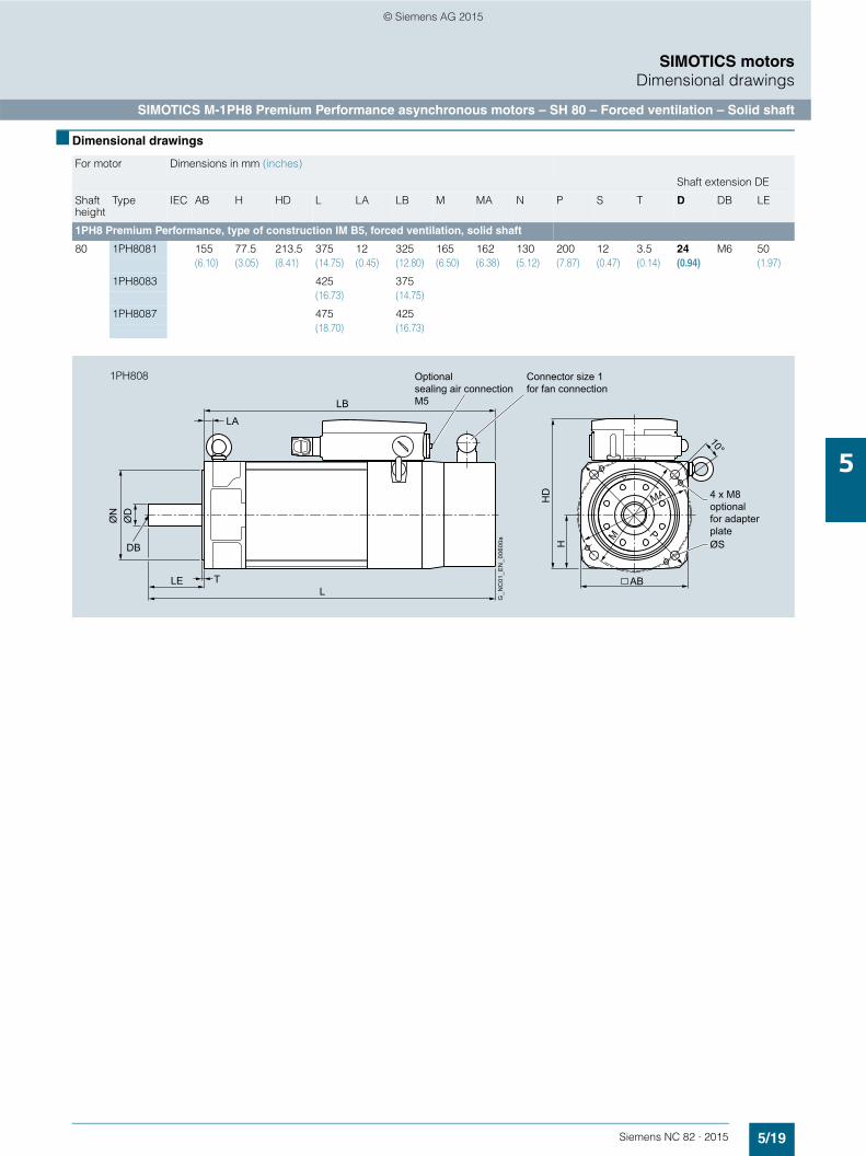
5/19Siemens NC 82 · 2015
SIMOTICS motorsDimensional drawings
SIMOTICS M-1PH8 Premium Performance asynchronous motors – SH 80 – Forced ventilation – Solid shaft
5
■ Dimensional drawings
For motor Dimensions in mm (inches)
Shaft extension DE
Shaft height
Type IEC AB H HD L LA LB M MA N P S T D DB LE
1PH8 Premium Performance, type of construction IM B5, forced ventilation, solid shaft
80 1PH8081 155 77.5 213.5 375 12 325 165 162 130 200 12 3.5 24 M6 50(6.10) (3.05) (8.41) (14.75) (0.45) (12.80) (6.50) (6.38) (5.12) (7.87) (0.47) (0.14) (0.94) (1.97)
1PH8083 425 375(16.73) (14.75)
1PH8087 475 425(18.70) (16.73)
G_N
C01
_EN
_006
00a
Connector size 1 for fan connection
Optionalsealing air connectionM5
4 x M8 optionalfor adapter plate
LA
ØD
ØN
TLEL
ØSPM
LB
HD
HDB
AB
10°
MA
1PH808
© Siemens AG 2015

5/20 Siemens NC 82 · 2015
SIMOTICS motorsDimensional drawings
SIMOTICS M-1PH8 Premium Performance asynchronous motors – SH 80 – Forced ventilation – Hollow shaft
5
■ Dimensional drawings
For motor Dimensions in mm (inches)
Shaft extension DE
Shaft height
Type IEC AB H HD L LA LB L1 M MA N P S T D E LE
1PH8 Premium Performance, type of construction IM B5, forced ventilation, hollow shaft
80 1PH8081 155 77.5 213.5 575 12 525 269.3 165 162 130 200 12 3.5 24 50 50(6.10) (3.05) (8.41) (22.64) (0.45) (20.67) (10.60) (6.50) (6.38) (5.12) (7.87) (0.47) (0.14) (0.94) (1.97) (1.97)
1PH8083 625 575 319.3(24.61) (22.64) (12.57)
1PH8087 675 625 369.3(26.57) (24.61) (14.54)
G_N
C01
_EN
_005
95a
Connector size 1 for fan connection
200 (7.97)
4 x M8Optionalfor adapter plate
Optionalsealing air connectionM5
ØS AB
ØD
ØN
HD
LE
LA
L1
LB
P
L ØM
H
T
10°
MA
1PH808
NDE shaft extensionDE shaft extension
G_PM21_EN_00173a
Ø8
(Ø0.
31)
13(0.51)
1.5(0.06)
2(0.08)
10.5
SW 19
(0.41)
31(1.22)
340.05 C (1.34)
E
0.002 C
C D
M12
x1.2
5-R
H
RZ16
RZ2
560
°
Ø16
H7
(Ø0.
63H
7 )
Ø0.04 CØ0.002 C
RZ6.3
60°
Ø14
(Ø0.
55
)
Ø14
.5(Ø
0.57
)
Ø0.007 DØ0.0003 D
+0.0
08-0
.001 +0
.000
3-0
.000
04
M12
x1.2
5-LH
0.005 D0.0002 D
18.5(0.73)
RZ6.3
1.5(0.06)
1PH808
© Siemens AG 2015

Siemens NC 82 · 2015
66/2 Built-on optoelectronic
rotary encoders6/2 Introduction6/2 Incremental encoders6/2 Incremental encoder with sin/cos 1 Vpp6/2 Incremental encoder with RS422 (TTL)6/4 Absolute encoders6/4 Absolute encoder with DRIVE-CLiQ6/6 Incremental/absolute encoders6/6 Accessories
Thanks to the open DRIVE-CLiQ interface, absolute encoders with integrated DRIVE-CLiQ interface from different manufacturers can be used.More information can be found at:http://support.automation.siemens.com/WW/view/en/65402168
Measuring systems
© Siemens AG 2015

6/2 Siemens NC 82 · 2015
Measuring systemsBuilt-on optoelectronic rotary encoders
Introduction Incremental encoders
6
■ Overview
Absolute encoders, incremental encoders and mounting accessories
The built-on optoelectronic rotary encoders sense distances, angles of rotation or speeds in machines. They can be used in conjunction with computerized numerical controls, programma-ble logic controllers, drives and position displays, e.g. for:• SINUMERIK CNC controls• SIMOTION Motion Control Systems• SIMATIC programmable logic controllers• SINAMICS drive systems
■ Application
A distinction is made between incremental and absolute measuring procedures:• In the case of incremental encoders, the machine must travel
to a reference point after each power-off state, as the position is not usually stored in the controller, and movements of the machine while the power is off are not recorded.
• Absolute encoders, on the other hand, also record these movements while the power is off and return the actual position after power on. Travel to a reference point is not necessary.
■ Design
All encoders are available in Synchro flange and clamp flange versions. Encoders with a Synchro flange can be attached to the machine with 3 clamps or mounted with axial screws. The en-coder is driven by means of a plug-in coupling or a spring disk coupling. Alternatively, pulleys can also be used.
The encoder supply voltage is 5 V DC or alternatively 10 V to 30 V DC. The 10 V to 30 V DC version supports longer cable lengths. Most control systems apply the supply voltage directly on the measuring circuit connector. With SINAMICS, the power supply for the measuring systems is provided via the Sensor Modules.
For rotary encoders with cables, the cable length including the connector is 1 m.
The following bending radii must be observed for the cable to the encoder:• One-time bending: ≥ 20 mm• Continuous bending: ≥ 75 mm
■ Function
Incremental encoder (sin/cos 1 Vpp/RS422) with cable and connector, clamp flange and Synchro flange
Incremental encoders deliver a defined number of electrical pulses per revolution, which represent the measurement of the traveled distance or angle.
Incremental encoders operate on the principle of optoelectronic scanning of dividing disks with the transmitted light principle. The light source is a light emitting diode (LED). The light-dark modulation generated as the encoder shaft rotates is picked up by photoelectronic elements. With an appropriate arrangement of the line pattern on the dividing disk connected to the shaft and the fixed aperture, the photoelectronic elements provide two trace signals A and B at 90° to one another, as well as a refer-ence signal R. The encoder electronics amplify these signals and convert them into different output levels.
The following output levels are available:• Analog signals sin/cos with 1 Vpp level
Better resolution can be achieved for encoders with sinusoidal signals by interpolating them in the higher-level controller.
• RS422 difference signals (TTL)In the case of RS422 incremental encoders (TTL), the resolu-tion can be improved by a factor of four by means of edge evaluation.
■ Technical specifications
Article No. 6FX2001-3.... 6FX2001-2....
Product designation Incremental encoder with sin/cos 1 Vpp
Incremental encoder with RS422 (TTL)
Operating voltage Vp on encoder
5 V DC ± 10 % 5 V DC ± 10 % or 10 ... 30 V DC
Limit frequency, typical ≥ 100 kHz (-3 dB)≥ 200 kHz (-6 dB)
–
Scanning frequency, maximum
– 300 kHz
No-load current consumption, maximum
150 mA 150 mA
Signal level Sinusoidal 1 Vpp RS422 (TTL)
Outputs protected against short-circuit to 0 V
Yes Yes
Switching time (10 ... 90 %) (for 1 m cable and recom-mended input circuit)
– Rise/fall timet+/t- ≤ 50 ns
Phase angle, signal A to B 90° ± 10°el. 90°
• Edge spacing, min. at 300 kHz
– ≥ 0.45 µs
© Siemens AG 2015

6/3Siemens NC 82 · 2015
Measuring systemsBuilt-on optoelectronic rotary encoders
Incremental encoders
6
■ Technical specifications (continued)
S/R = signals/revolution
■ Selection and ordering data
Article No. 6FX2001-3.... 6FX2001-2....
Product designation Incremental encoder with sin/cos 1 Vpp
Incremental encoder with RS422 (TTL)
Cable length to down-stream electronics, maximum1)
150 m 100 m
LED failure monitoring – High-resistance driver
Resolution, maximum 2500 S/R 5000 S/R
Accuracy (in angular seconds)
± 18 mech. × 3600/number of signals/revolution z
± 18 mech. × 3600/number of signals/revolution z
Speed, maximum
• Electrical (18 × 106 rpm)/number of signals/revolution (at -6 dB)
(18 × 106 rpm)/number of signals/revolution
• Mechanical 12000 rpm 12000 rpm
Friction torque (at 20 °C) ≤ 0.01 Nm ≤ 0.01 Nm
Starting torque (at 20 °C) ≤ 0.01 Nm ≤ 0.01 Nm
Shaft loading capacity
• n ≤ 6000 rpm
- Axial 40 N 40 N
- Radial at shaft extension 60 N 60 N
• n > 6000 rpm
- Axial 10 N 10 N
- Radial at shaft extension 20 N 20 N
Shaft diameter
• Synchro flange 6 mm 6 mm
• Clamp flange 10 mm 10 mm
Shaft length
• Synchro flange 10 mm 10 mm
• Clamp flange 20 mm 20 mm
Angular acceleration, maximum
105 rad/s2 105 rad/s2
Moment of inertia of rotor 1.45 × 10⁻⁶ kgm2 1.45 × 10⁻⁶ kgm2
Vibration (55 … 2000 Hz) to EN 60068-2-6
≤ 300 m/s2 ≤ 300 m/s2
Shock acc. to EN 60068-2-27
• 2 ms ≤ 2000 m/s2 ≤ 2000 m/s2
• 6 ms ≤ 1000 m/s2 ≤ 1000 m/s2
Degree of protection
• Without shaft input IP67 IP67
• With shaft input IP64 IP64
Ambient temperature
Operation
• Flange outlet or fixed cable
- At Vp = 5 V ±10 % -40 ... +100 °C -40 ... +100 °C
- At Vp = 10 … 30 V – -40 ... +70 °C
• Flexible cable
- At Vp = 5 V ±10 % -10 ... +100 °C -10 ... +100 °C
- At Vp = 10 … 30 V – -10 ... +70 °C
Net weight 0.3 kg 0.3 kg
EMC Tested in accordance with the guide-lines for electromagnetic compatibility 89/336/EEC and the regulations of the EMC guidelines (generic standards)
Certificate of suitability CE, cULus CE, cULus
Description Article No.
Incremental encoder with sin/cos 1 Vpp
5 V DC supply voltage Synchro flange and connection via
• Axial flange outlet 6FX2001-3G 7 7 7
• Radial flange outlet 6FX2001-3E 7 7 7
• Cable 1 m with connector2) 6FX2001-3C 7 7 7
Resolution 1000 S/R B 0 01024 S/R B 0 22500 S/R C 5 0
Incremental encoder with RS422 (TTL)
5 V DC supply voltageSynchro flange and connection via
• Axial flange outlet 6FX2001-2G 7 7 7
• Radial flange outlet 6FX2001-2E 7 7 7
• Cable 1 m with connector2) 6FX2001-2C 7 7 7
Clamp flange and connection via
• Axial flange outlet 6FX2001-2R 7 7 7
• Radial flange outlet 6FX2001-2P 7 7 7
• Cable 1 m with connector2) 6FX2001-2M 7 7 7
10 ... 30 V DC supply voltageSynchro flange and connection via
• Axial flange outlet 6FX2001-2H 7 7 7
• Radial flange outlet 6FX2001-2F 7 7 7
• Cable 1 m with connector2) 6FX2001-2D 7 7 7
Clamp flange and connection via
• Axial flange outlet 6FX2001-2S 7 7 7
• Radial flange outlet 6FX2001-2Q 7 7 7
• Cable 1 m with connector2) 6FX2001-2N 7 7 7
Resolution 500 S/R A 5 01000 S/R B 0 01024 S/R B 0 21250 S/R B 2 51500 S/R B 5 02000 S/R C 0 02048 S/R C 0 42500 S/R C 5 03600 S/R D 6 05000 S/R F 0 0
1) With recommended cable and input circuitry of the downstream electronics, observe max. permissible cable length of module to be evaluated.
2) Universal integrated cable outlet for axial and radial outlet direction.
© Siemens AG 2015
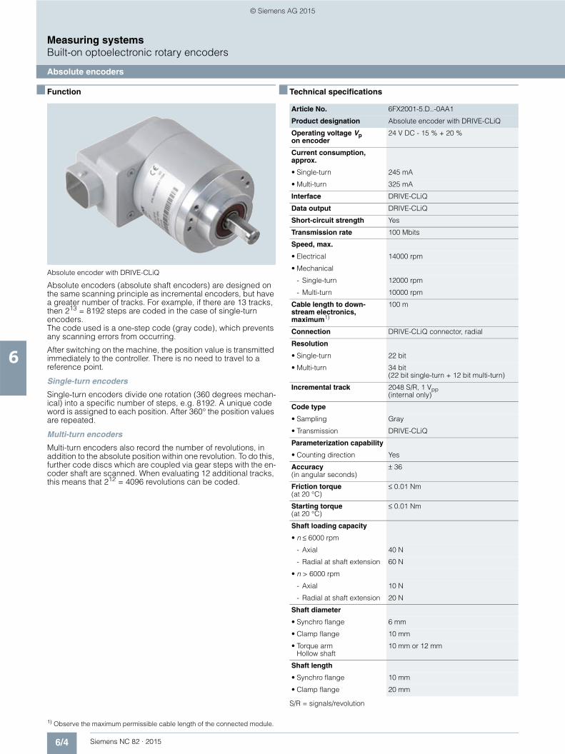
6/4 Siemens NC 82 · 2015
Measuring systemsBuilt-on optoelectronic rotary encoders
Absolute encoders
6
■ Function
Absolute encoder with DRIVE-CLiQ
Absolute encoders (absolute shaft encoders) are designed on the same scanning principle as incremental encoders, but have a greater number of tracks. For example, if there are 13 tracks, then 213 = 8192 steps are coded in the case of single-turn encoders. The code used is a one-step code (gray code), which prevents any scanning errors from occurring.
After switching on the machine, the position value is transmitted immediately to the controller. There is no need to travel to a reference point.
Single-turn encoders
Single-turn encoders divide one rotation (360 degrees mechan-ical) into a specific number of steps, e.g. 8192. A unique code word is assigned to each position. After 360° the position values are repeated.
Multi-turn encoders
Multi-turn encoders also record the number of revolutions, in addition to the absolute position within one revolution. To do this, further code discs which are coupled via gear steps with the en-coder shaft are scanned. When evaluating 12 additional tracks, this means that 212 = 4096 revolutions can be coded.
■ Technical specifications
S/R = signals/revolution
Article No. 6FX2001-5.D..-0AA1
Product designation Absolute encoder with DRIVE-CLiQ
Operating voltage Vp on encoder
24 V DC - 15 % + 20 %
Current consumption, approx.
• Single-turn 245 mA
• Multi-turn 325 mA
Interface DRIVE-CLiQ
Data output DRIVE-CLiQ
Short-circuit strength Yes
Transmission rate 100 Mbits
Speed, max.
• Electrical 14000 rpm
• Mechanical
- Single-turn 12000 rpm
- Multi-turn 10000 rpm
Cable length to down-stream electronics, maximum1)
100 m
Connection DRIVE-CLiQ connector, radial
Resolution
• Single-turn 22 bit
• Multi-turn 34 bit(22 bit single-turn + 12 bit multi-turn)
Incremental track 2048 S/R, 1 Vpp (internal only)
Code type
• Sampling Gray
• Transmission DRIVE-CLiQ
Parameterization capability
• Counting direction Yes
Accuracy (in angular seconds)
± 36
Friction torque (at 20 °C)
≤ 0.01 Nm
Starting torque (at 20 °C)
≤ 0.01 Nm
Shaft loading capacity
• n ≤ 6000 rpm
- Axial 40 N
- Radial at shaft extension 60 N
• n > 6000 rpm
- Axial 10 N
- Radial at shaft extension 20 N
Shaft diameter
• Synchro flange 6 mm
• Clamp flange 10 mm
• Torque arm Hollow shaft
10 mm or 12 mm
Shaft length
• Synchro flange 10 mm
• Clamp flange 20 mm
1) Observe the maximum permissible cable length of the connected module.
© Siemens AG 2015

6/5Siemens NC 82 · 2015
Measuring systemsBuilt-on optoelectronic rotary encoders
Absolute encoders
6
■ Technical specifications (continued) ■ Selection and ordering data
Article No. 6FX2001-5.D..-0AA1
Product designation Absolute encoder with DRIVE-CLiQ
Angular acceleration, maximum
105 rad/s2
Moment of inertia of rotor
• Solid shaft 1.90 × 10⁻⁶ kgm2
• Hollow shaft 2.80 × 10⁻⁶ kgm2
Vibration (55 … 2000 Hz) acc. to EN 60068-2-6
≤ 100 m/s2
Shock acc. to EN 60068-2-27
• 2 ms ≤ 2000 m/s2
• 6 ms ≤ 1000 m/s2
Degree of protection
• Without shaft input IP67
• With shaft input IP64
Ambient temperature, during
• operation -20 ... +100 °C
Net weight
• Single-turn 0.4 kg
• Multi-turn 0.5 kg
EMC Tested in accordance with DIN EN 50081 and EN 50082
Certificate of suitability CE, cULus
Description Article No.
Absolute encoder with DRIVE-CLiQ
24 V DC supply voltageRadial connection
• Synchro flangeSolid shaft
6FX2001-5FD 7 7 -0AA1
• Clamp flange Solid shaft
6FX2001-5QD 7 7 -0AA1
• Torque armHollow shaft diameter 10 mm
6FX2001-5VD 7 7 -0AA1
• Torque armHollow shaft diameter 12 mm
6FX2001-5WD 7 7 -0AA1
Resolution
• Single-turn 22 bit 1 3
• Multi-turn 34 bit 2 5
© Siemens AG 2015
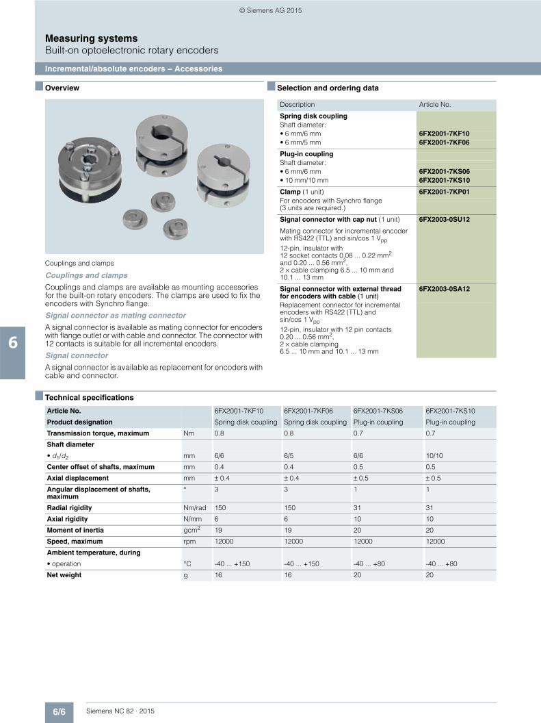
6/6 Siemens NC 82 · 2015
Measuring systemsBuilt-on optoelectronic rotary encoders
Incremental/absolute encoders – Accessories
6
■ Overview
Couplings and clamps
Couplings and clamps
Couplings and clamps are available as mounting accessories for the built-on rotary encoders. The clamps are used to fix the encoders with Synchro flange.
Signal connector as mating connector
A signal connector is available as mating connector for encoders with flange outlet or with cable and connector. The connector with 12 contacts is suitable for all incremental encoders.
Signal connector
A signal connector is available as replacement for encoders with cable and connector.
■ Selection and ordering data
■ Technical specifications
Description Article No.
Spring disk couplingShaft diameter:• 6 mm/6 mm 6FX2001-7KF10• 6 mm/5 mm 6FX2001-7KF06
Plug-in couplingShaft diameter:• 6 mm/6 mm 6FX2001-7KS06• 10 mm/10 mm 6FX2001-7KS10
Clamp (1 unit) 6FX2001-7KP01For encoders with Synchro flange(3 units are required.)
Signal connector with cap nut (1 unit) 6FX2003-0SU12
Mating connector for incremental encoder with RS422 (TTL) and sin/cos 1 Vpp
12-pin, insulator with 12 socket contacts 0.08 ... 0.22 mm2
and 0.20 ... 0.56 mm2, 2 × cable clamping 6.5 ... 10 mm and 10.1 ... 13 mm
Signal connector with external thread for encoders with cable (1 unit)
6FX2003-0SA12
Replacement connector for incremental encoders with RS422 (TTL) and sin/cos 1 Vpp
12-pin, insulator with 12 pin contacts 0.20 ... 0.56 mm2, 2 × cable clamping 6.5 ... 10 mm and 10.1 ... 13 mm
Article No. 6FX2001-7KF10 6FX2001-7KF06 6FX2001-7KS06 6FX2001-7KS10
Product designation Spring disk coupling Spring disk coupling Plug-in coupling Plug-in coupling
Transmission torque, maximum Nm 0.8 0.8 0.7 0.7
Shaft diameter
• d1/d2 mm 6/6 6/5 6/6 10/10
Center offset of shafts, maximum mm 0.4 0.4 0.5 0.5
Axial displacement mm ± 0.4 ± 0.4 ± 0.5 ± 0.5
Angular displacement of shafts, maximum
° 3 3 1 1
Radial rigidity Nm/rad 150 150 31 31
Axial rigidity N/mm 6 6 10 10
Moment of inertia gcm2 19 19 20 20
Speed, maximum rpm 12000 12000 12000 12000
Ambient temperature, during
• operation °C -40 ... +150 -40 ... +150 -40 ... +80 -40 ... +80
Net weight g 16 16 20 20
© Siemens AG 2015
Siemens NC 82 · 2015
77/2 Introduction7/2 General information
7/4 Connection overviews7/4 SINUMERIK 828D BASIC7/5 SINUMERIK 828D7/6 SINAMICS S120 Motor Modules
in booksize format7/7 SINAMICS S120 Combi
Power Modules7/8 SINUMERIK PP 72/48D PN and
PP 72/48D 2/2A PN I/O modules7/8 SINAMICS S120 Sensor Module
Cabinet-Mounted SMC207/9 SINAMICS S120 Sensor Module
Cabinet-Mounted SMC307/9 SINAMICS S120 Sensor Module
Cabinet-Mounted SMC40
7/10 Power cables7/11 Power cables for
SIMOTICS S-1FK7 motors with SPEED-CONNECT connector
7/12 Power cables for SIMOTICS M-1PH8 motors with terminal box
7/13 Signal cables7/15 Pre-assembled
DRIVE-CLiQ signal cables7/15 Pre-assembled MOTION-CONNECT
DRIVE-CLiQ signal cables7/16 Signal cables for direct or external
measuring systems with full-thread connector
7/17 Length code
MOTION-CONNECT connection systems
© Siemens AG 2015
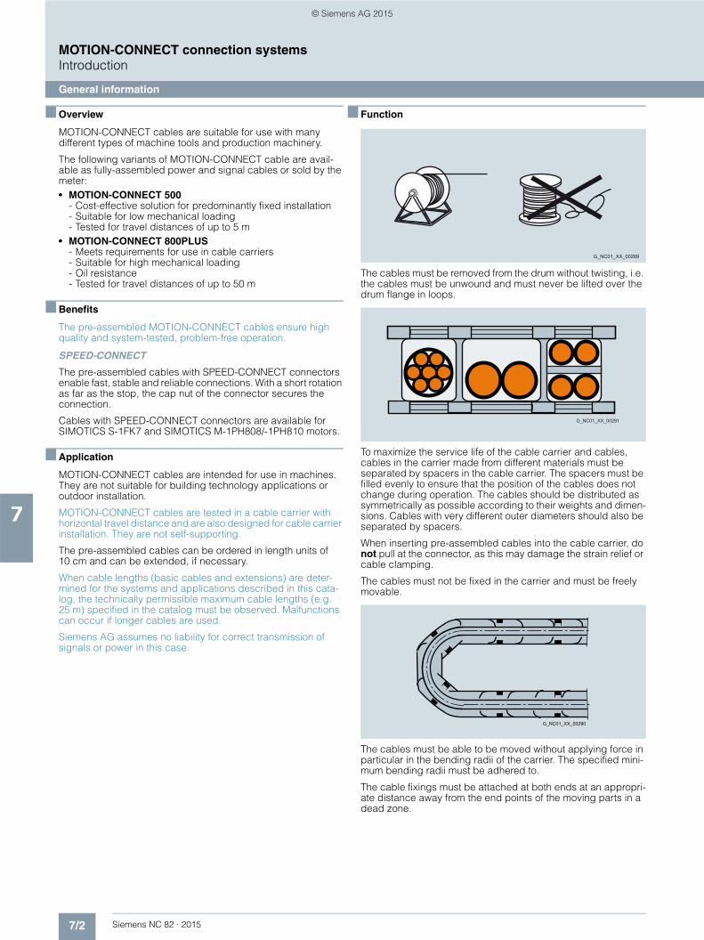
7/2 Siemens NC 82 · 2015
MOTION-CONNECT connection systemsIntroduction
General information
7
■ Overview
MOTION-CONNECT cables are suitable for use with many different types of machine tools and production machinery.
The following variants of MOTION-CONNECT cable are avail-able as fully-assembled power and signal cables or sold by the meter:• MOTION-CONNECT 500
- Cost-effective solution for predominantly fixed installation- Suitable for low mechanical loading- Tested for travel distances of up to 5 m
• MOTION-CONNECT 800PLUS- Meets requirements for use in cable carriers- Suitable for high mechanical loading- Oil resistance- Tested for travel distances of up to 50 m
■ Benefits
The pre-assembled MOTION-CONNECT cables ensure high quality and system-tested, problem-free operation.
SPEED-CONNECT
The pre-assembled cables with SPEED-CONNECT connectors enable fast, stable and reliable connections. With a short rotation as far as the stop, the cap nut of the connector secures the connection.
Cables with SPEED-CONNECT connectors are available for SIMOTICS S-1FK7 and SIMOTICS M-1PH808/-1PH810 motors.
■ Application
MOTION-CONNECT cables are intended for use in machines. They are not suitable for building technology applications or outdoor installation.
MOTION-CONNECT cables are tested in a cable carrier with horizontal travel distance and are also designed for cable carrier installation. They are not self-supporting.
The pre-assembled cables can be ordered in length units of 10 cm and can be extended, if necessary.
When cable lengths (basic cables and extensions) are deter-mined for the systems and applications described in this cata-log, the technically permissible maximum cable lengths (e.g. 25 m) specified in the catalog must be observed. Malfunctions can occur if longer cables are used.
Siemens AG assumes no liability for correct transmission of signals or power in this case.
■ Function
The cables must be removed from the drum without twisting, i.e. the cables must be unwound and must never be lifted over the drum flange in loops.
To maximize the service life of the cable carrier and cables, cables in the carrier made from different materials must be separated by spacers in the cable carrier. The spacers must be filled evenly to ensure that the position of the cables does not change during operation. The cables should be distributed as symmetrically as possible according to their weights and dimen-sions. Cables with very different outer diameters should also be separated by spacers.
When inserting pre-assembled cables into the cable carrier, do not pull at the connector, as this may damage the strain relief or cable clamping.
The cables must not be fixed in the carrier and must be freely movable.
The cables must be able to be moved without applying force in particular in the bending radii of the carrier. The specified mini-mum bending radii must be adhered to.
The cable fixings must be attached at both ends at an appropri-ate distance away from the end points of the moving parts in a dead zone.
G_NC01_XX_00289
G_NC01_XX_00291
G_NC01_XX_00290
© Siemens AG 2015
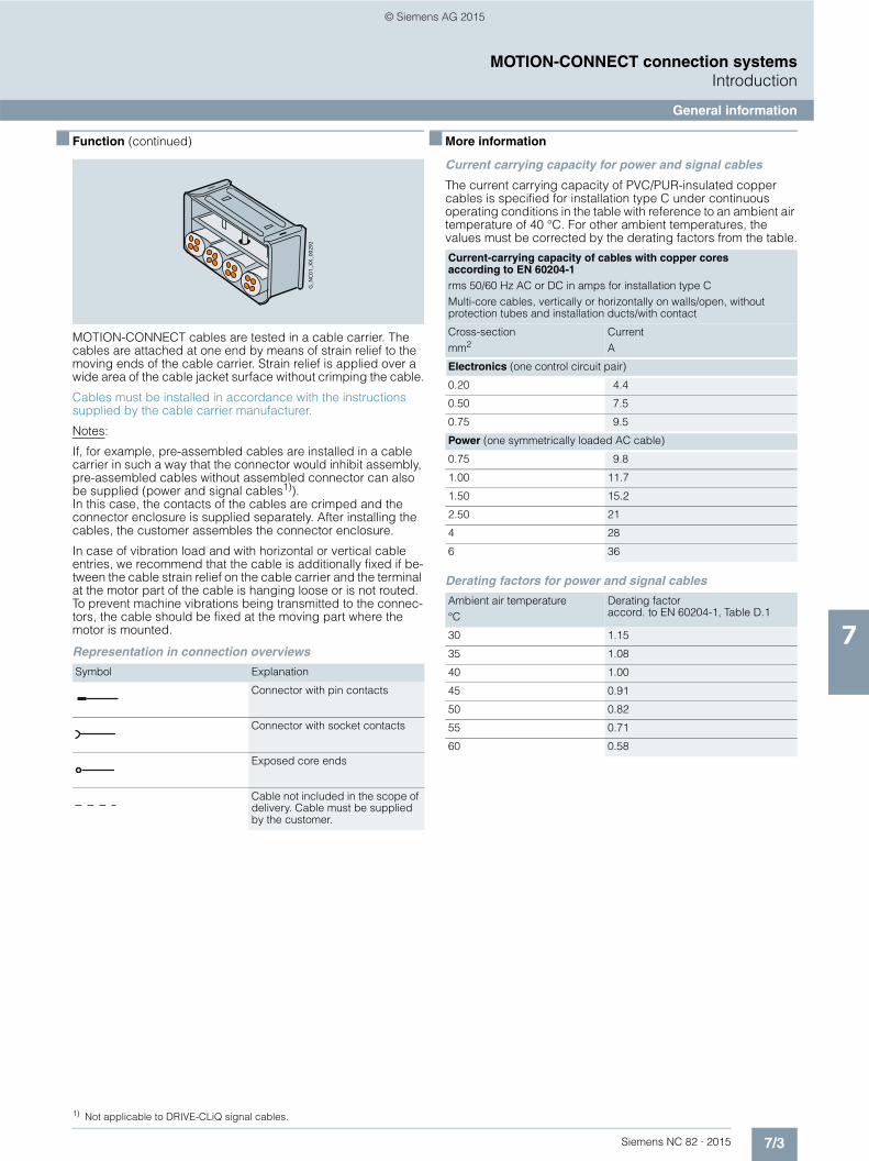
7/3Siemens NC 82 · 2015
MOTION-CONNECT connection systemsIntroduction
General information
7
■ Function (continued)
MOTION-CONNECT cables are tested in a cable carrier. The cables are attached at one end by means of strain relief to the moving ends of the cable carrier. Strain relief is applied over a wide area of the cable jacket surface without crimping the cable.
Cables must be installed in accordance with the instructions supplied by the cable carrier manufacturer.
Notes:
If, for example, pre-assembled cables are installed in a cable carrier in such a way that the connector would inhibit assembly, pre-assembled cables without assembled connector can also be supplied (power and signal cables1)). In this case, the contacts of the cables are crimped and the connector enclosure is supplied separately. After installing the cables, the customer assembles the connector enclosure.
In case of vibration load and with horizontal or vertical cable entries, we recommend that the cable is additionally fixed if be-tween the cable strain relief on the cable carrier and the terminal at the motor part of the cable is hanging loose or is not routed. To prevent machine vibrations being transmitted to the connec-tors, the cable should be fixed at the moving part where the motor is mounted.
Representation in connection overviews
■ More information
Current carrying capacity for power and signal cables
The current carrying capacity of PVC/PUR-insulated copper cables is specified for installation type C under continuous operating conditions in the table with reference to an ambient air temperature of 40 °C. For other ambient temperatures, the values must be corrected by the derating factors from the table.
Derating factors for power and signal cables
Symbol Explanation
Connector with pin contacts
Connector with socket contacts
Exposed core ends
Cable not included in the scope of delivery. Cable must be supplied by the customer.
G_N
C01
_XX_
0029
2
1) Not applicable to DRIVE-CLiQ signal cables.
Current-carrying capacity of cables with copper cores according to EN 60204-1rms 50/60 Hz AC or DC in amps for installation type CMulti-core cables, vertically or horizontally on walls/open, without protection tubes and installation ducts/with contact
Cross-sectionmm2
CurrentA
Electronics (one control circuit pair)
0.20 4.4
0.50 7.5
0.75 9.5
Power (one symmetrically loaded AC cable)
0.75 9.8
1.00 11.7
1.50 15.2
2.50 21
4 28
6 36
Ambient air temperature°C
Derating factoraccord. to EN 60204-1, Table D.1
30 1.15
35 1.08
40 1.00
45 0.91
50 0.82
55 0.71
60 0.58
© Siemens AG 2015

7/4 Siemens NC 82 · 2015
MOTION-CONNECT connection systemsConnection overviews
7
■ Integration
Connection overview of SINUMERIK 828D BASIC
DRIVE-CLiQ
Electronic handwheel (up to 2)
USB memory device Card reader
Ethernet cableProgramming device, PC
Modem router (remote diagnostics)
DRIVE-CLiQ cable ≤ 50 m (164 ft)
Power supply
Article No.Pre-assembled cables
Port 1 X120 Port 2 X120
SINAUT MD720-3 GSM/GPRS modem
Factory network
≤ 10 m (32 ft)
≤ 100 m (328 ft)
Ethernet cable≤ 100 m (328 ft)
X124 V DC
X127Ethernet OP front
Ethernet PPU rear X130
X143
X140RS232C
PLC I/O
6NH7701-5AN (length: 2.5 m (8.2 ft))≤ 3 m (9.8 ft)
6SL3060-4A..0-0AA0 (in fixed lengths)≤ 5 m (1.64 ft)6FX2002-1DC00-1..0 (by the meter)≤ 70 m (230 ft)
6FX8002-2BB01-1A..≤ 3 m (9.8 ft)
USB cable≤ 3 m (9.8 ft)
USB cable0.8 m (2.6 ft) (included in scope of delivery)
Handwheels
X125USB OP front
CF card OP front
X135USB PPU rear
X100X101X102
SINAMICS S120 Combi
Terminal ModuleTM54F
G_NC01_EN_00577c
SINUMERIKMCP Interface PN
SINUMERIKI/O modulePP 72/48D PN/PP 72/48D 2/2A PN
SIMATIC DP PN/PN coupler
Digital I Digital I/O
Digital I/O
Drive: 12 digital inputs 8 digital inputs/outputs
CNC:8 digital inputs8 digital outputsAnalog spindle (X252)
X122X132
X242X252 ≤ 30 m (98 ft)
≤ 30 m (98 ft)
MCP 310 USBMCP 483 USB
SINUMERIK 828D BASIC PPU 240.3/PPU 241.3
© Siemens AG 2015

7/5Siemens NC 82 · 2015
MOTION-CONNECT connection systemsConnection overviews
7
■ Integration (continued)
Connection overview of SINUMERIK 828D
Digital I Digital I/O
Digital I/O
DRIVE-CLiQ
Electronic handwheel (up to 2)
USB memory deviceCard reader
Ethernet cableProgramming device, PC
Modem router (remote diagnostics)
DRIVE-CLiQ cable≤ 50 m (164 ft)
Power supply
Article No.Pre-assembled cables
Drive: 12 digital inputs 8 digital inputs/outputs
CNC:8 digital inputs8 digital outputsAnalog spindle (X252)
Port 1 X120 Port 21) X120
SINAUT MD720-3 GSM/GPRS modem
Factory networkEthernet cable
X124 V DC
X127Ethernet OP front
Ethernet PPU rear X130
X143
X140RS232C
PLC I/O
6NH7701-5AN (length: 2.5 m (8.2 ft))≤ 3 m (9.8 ft)
6SL3060-4A..0-0AA0 (in fixed lengths)≤ 5 m (1.64 ft)6FX2002-1DC00-1..0 (by the meter)≤ 70 m (230 ft)
6FX8002-2BB01-1A..≤ 3 m (9.8 ft)
USB cable≤ 3 m (9.8 ft)
USB cable0.8 m (2.6 ft) (included in scope of delivery)
Handwheels
X125USB OP front
CF card OP front
X135USB PPU rear
1) Only with SW 26x for Milling.Only with SW 28x for Turning and Milling.Only with SW 28xA for Turning, Milling and G-Tech.
2) Only with SW 28xA for Turning and G-Tech.
X100X101X102
X122X132
X242X252
SINAMICS S120
Terminal ModuleTM54F
SINUMERIKMCP Interface PN
SINUMERIKI/O modulePP 72/48D PN/PP 72/48D 2/2A PN
SIMATIC DP PN/PN coupler
G_NC01_EN_00578b
≤ 30 m (98 ft)
≤ 100 m (328 ft)
≤ 100 m (328 ft)
≤ 10 m (32 ft)
≤ 30 m (98 ft)
NX10.31)
NX15.32)
MCP 310 USBMCP 483 USB
SINUMERIK 828D PPU 260.3/PPU 261.3PPU 280.3/PPU 281.3
© Siemens AG 2015

7/6 Siemens NC 82 · 2015
MOTION-CONNECT connection systemsConnection overviews
7
■ Integration (continued)
Connection overview of SINAMICS S120 Motor Modules in booksize format
Article No.Pre-assembled cablesMotor Module
FurtherMotor Modules
Pre-assembled power cables, see power cables for motors(max. cable length, see technical specifications of Motor Modules)
Motor encoder in motors with DRIVE-CLiQ interface 1FK7/1PH8
Motors
Motor encoder interface for motors with DRIVE-CLiQ interface
Motor connection
Booksize format
SINAMICS S120
1) For Single Motor Module: X200-X202 For Double Motor Module: X200-X203
Motor encoder interface via SMC for motors without DRIVE-CLiQ interface
G_NC01_EN_00579a
NX10.3/NX15.3
SINUMERIK 828D
Motor Module
Active Line Module
Smart Line Module
1)
1)
≤ 100 m (328 ft)
≤ 75 m (246 ft)
≤ 70 m (230 ft)
≤ 70 m (230 ft)
6SL3060-4A..0-0AA0≤ 5 m (1.64 ft)6FX2002-1DC00-....
6SL3060-4A..0-0AA0≤ 5 m (1.64 ft)6FX2002-1DC00-....
6FX5002- 2DC10-....
6FX8002- 2DC10-....
≤ 5 m (1.64 ft)
≤ 70 m (230 ft)
6SL3060-4A..0-0AA0
6FX2002-1DC00-....
X200-X203
X200-X203
X200-X203
1)
1)
1)
1)X200-X203
X200-X203
X100
X500 SMC10
X500 SMC20
X500 SMC30
X500 SMC40
X200-X203
X200-X202
X200-X202
© Siemens AG 2015

7/7Siemens NC 82 · 2015
MOTION-CONNECT connection systemsConnection overviews
7
■ Integration (continued)
Connection overview of SINAMICS S120 Combi Power Modules
SINAMICS S120DRIVE-CLiQ Hub Module DMC20
Direct linear incremental encoder sin/cos 1 VppLS 187(C)/LF 183(C)LB 382(C)LS 487(C)/LF 481(C)
Incremental encoder sin/cos 1 Vpp
RS422 incremental encoder (TTL)
Motor encoder in motorswith DRIVE-CLiQ interface 1FK7/1PH8
1FK7 motor without brakewith quick-release lock
1FK7 motor with brakewith quick-release lock
1PH808 motorwith terminal box
1PH810 motorwith terminal box
1PH813 motorwith terminal box
Adapter cable2)
SINAMICS S120Terminal Module TM54F
SINAMICS S120 Sensor Module Cabinet-Mounted SMC20
Motor encoderinterface formotors withDRIVE-CLiQinterface
SINAMICS S120 Motor Modules Booksize compact
Motor connection
Motor connection
Brake connection
G_N
C01
_EN
_004
32e
1) For standard configuration with the modules mounted directly adjacent to one another.2) Adapter cable available from measuring system manufacturer.
≤ 25 m (82 ft)
≤ 25 m (82 ft)
≤ 25 m (82 ft)
≤ 25 m (82 ft)
≤ 25 m (82 ft)
Article No.Pre-assembled cables
≤ 70 m (230 ft)
(164 ft)
≤ 100 m (328 ft)
≤ 100 m (328 ft)at 5 V DC
≤ 75 m (246 ft)
≤ 5 m (1.64 ft)
SINAMICS S120 Combi Power Module
SINUMERIK 828D BASIC
X200
X220
X11
X2
X3X4 X5
X201X202X203X204
X101
X100
X200
X500
X501
X500
X520
X102
X500
X501 ... X505
6FX2002-1DC00-....
6SL3060-4A..0-0AA01)
6FX8002-2DC10-….
6FX.002-2CR00-….
6FX.002-5CF1.-….
6FX.002-5CE02-….
6FX.002-5CE04-….
6FX.002-5CE06-….
6FX.002-5DF1.-….
6FX5002-2DC10-….
6FX.002-2CG00-….≤ 50 m 6FX2001-3...
6FX2001-2...
© Siemens AG 2015
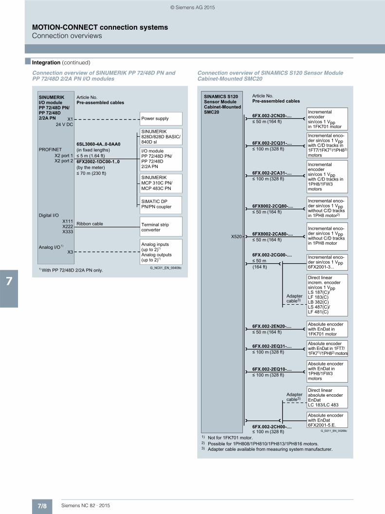
7/8 Siemens NC 82 · 2015
MOTION-CONNECT connection systemsConnection overviews
7
■ Integration (continued)
Connection overview of SINUMERIK PP 72/48D PN and PP 72/48D 2/2A PN I/O modules
Connection overview of SINAMICS S120 Sensor Module Cabinet-Mounted SMC20
SINUMERIKI/O module PP 72/48D PN/ PP 72/48D 2/2A PN
SINUMERIK MCP 310C PN/MCP 483C PN
I/O module PP 72/48D PN/ PP 72/48D 2/2A PN
Power supply
Analog inputs (up to 2)1)
Analog outputs (up to 2)1)
Ribbon cable
PROFINET
Digital I/O
Analog I/O X3
24 V DC
X2 port 1X2 port 2
X111X222X333
6SL3060-4A..0-0AA0(in fixed lengths)≤ 5 m (1.64 ft)6FX2002-1DC00-1..0(by the meter)≤ 70 m (230 ft)
X1
Article No.Pre-assembled cables
G_NC01_EN_00409c1) With PP 72/48D 2/2A PN only.
Terminal strip converter
1)
SIMATIC DPPN/PN coupler
SINUMERIK 828D/828D BASIC/840D sl
Absolute encoder with EnDat in 1PH8/1FW3 motors
Adapter cable3)
Direct linearabsolute encoder EnDat LC 183/LC 483
Absolute encoder with EnDat 6FX2001-5.E.
Adapter cable3)
Incremental enco- der sin/cos 1 Vpp 6FX2001-3...
Direct linearincrem. encoder sin/cos 1 VppLS 187(C)/LF 183(C)LB 382(C)LS 487(C)/LF 481(C)
Incremental encodersin/cos 1 Vpp with C/D tracks in 1PH8/1FW3 motors
Incremental enco-der sin/cos 1 Vpp with C/D tracks in 1FT7/1FK71)/1PH82) motors
Incremental enco- der sin/cos 1 Vpp without C/D tracks in 1PH8 motor2)
Incremental enco- der sin/cos 1 Vpp without C/D tracks in 1PH8 motor
Incremental encodersin/cos 1 Vpp in 1FK701 motor
Absolute encoder with EnDat in1FK701 motor
Absolute encoder with EnDat in 1FT7/ 1FK71)/1PH82) motors
G_D211_EN_00268c
1) Not for 1FK701 motor.
3) Adapter cable available from measuring system manufacturer. 2) Possible for 1PH808/1PH810/1PH813/1PH816 motors.
Article No.Pre-assembled cables
(164 ft)
(328 ft)
(328 ft)
(164 ft)
(164 ft)
(164 ft)
(164 ft)
(328 ft)
(328 ft)
(328 ft)
6FX.002-2EQ10-....≤ 100 m
6FX.002-2CH00-....≤ 100 m
6FX.002-2CA31-....≤ 100 m
6FX.002-2CQ31-....≤ 100 m
6FX8002-2CQ80-....≤ 50 m
6FX.002-2CG00-....≤ 50 m
6FX8002-2CA80-....≤ 50 m
6FX.002-2CN20-....≤ 50 m
6FX.002-2EN20-....≤ 50 m
6FX.002-2EQ31-....≤ 100 m
X520
SINAMICS S120Sensor ModuleCabinet-MountedSMC20
© Siemens AG 2015

7/9Siemens NC 82 · 2015
MOTION-CONNECT connection systemsConnection overviews
7
■ Integration (continued)
Connection overview of SINAMICS S120 Sensor Module Cabinet-Mounted SMC30
Connection overview of SINAMICS S120 Sensor Module Cabinet-Mounted SMC40
TTL incremental encoder RS 422 (5 V DC)6FX2001-2...
TTL incremental encoder RS 422 (24 V DC)6FX2001-2...
HTL incremental encoder in 1PH8 motor
1) Applies to HTL encoders with bipolar signal evaluation or for evaluation of difference signals A*, A and B*, B; for HTL encoders with unipolar signal evaluation the permissible cable length is reduced to 100 m (328 ft).
Absolute encoderwith SSI (24 V DC)6FX2001-5.S.
HTL incremental encoder 24 V 6FX2001-4....
(328 ft)
(328 ft)
(328 ft)
(328 ft)
(984 ft)G_D211_EN_00269c
Article No.Pre-assembled cables
6FX.002-2AH00-....≤ 300 m1)
6FX.002-2CR00-....≤ 100 m
6FX.002-2CD24-....≤ 100 m
6FX.002-2CC11-....≤ 100 m
6FX5002-2CA12-....≤ 100 m
X520
X521X531
SINAMICS S120Sensor ModuleCabinet-MountedSMC30
Absolute encoder with EnDat 2.2
G_NC01_EN_00580
1) Adapter cable between SMC40 and absolute encoder with EnDat 2.2 available from encoder manufacturer.
Adapter cable 1)
Article No.Pre-assembled cables
X520/1 X520/2
SINAMICS S120Sensor ModuleCabinet-MountedSMC40
© Siemens AG 2015
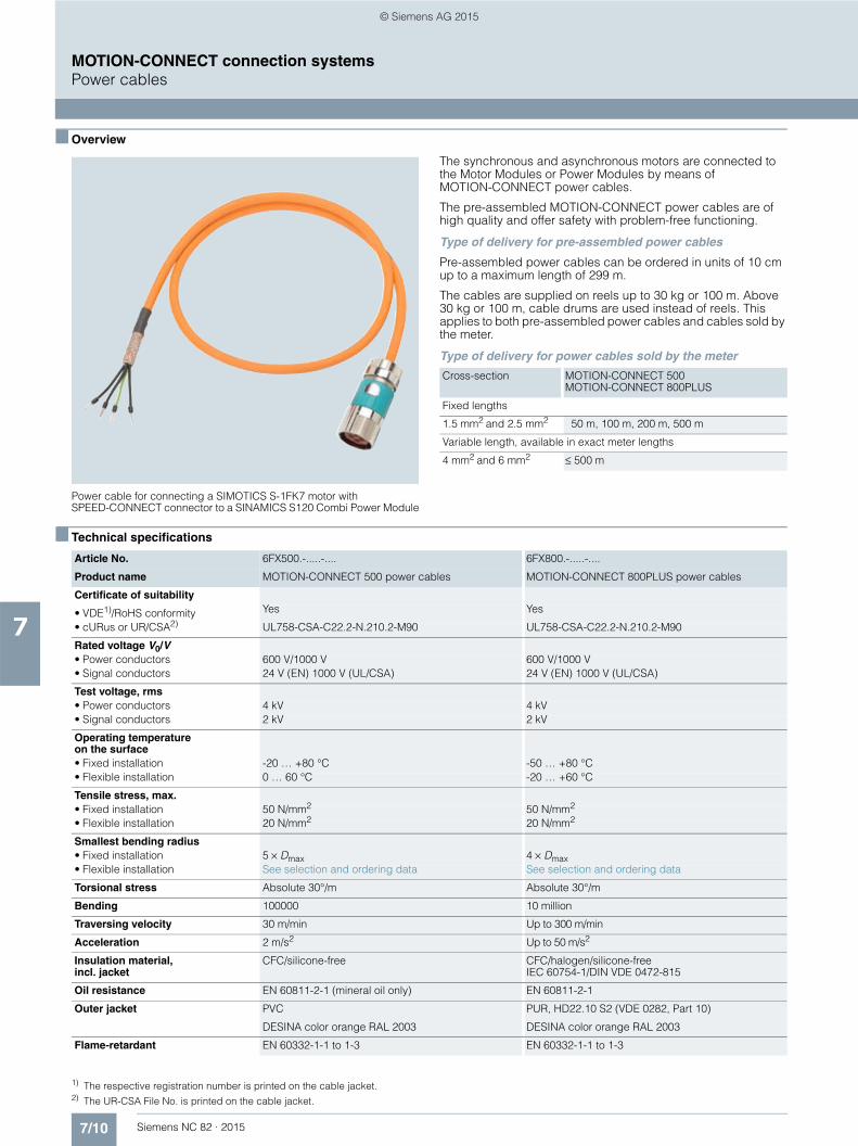
7/10 Siemens NC 82 · 2015
MOTION-CONNECT connection systemsPower cables
7
■ Overview
Power cable for connecting a SIMOTICS S-1FK7 motor with SPEED-CONNECT connector to a SINAMICS S120 Combi Power Module
The synchronous and asynchronous motors are connected to the Motor Modules or Power Modules by means of MOTION-CONNECT power cables.
The pre-assembled MOTION-CONNECT power cables are of high quality and offer safety with problem-free functioning.
Type of delivery for pre-assembled power cables
Pre-assembled power cables can be ordered in units of 10 cm up to a maximum length of 299 m.
The cables are supplied on reels up to 30 kg or 100 m. Above 30 kg or 100 m, cable drums are used instead of reels. This applies to both pre-assembled power cables and cables sold by the meter.
Type of delivery for power cables sold by the meter
■ Technical specifications
Cross-section MOTION-CONNECT 500MOTION-CONNECT 800PLUS
Fixed lengths
1.5 mm2 and 2.5 mm2 50 m, 100 m, 200 m, 500 m
Variable length, available in exact meter lengths
4 mm2 and 6 mm2 ≤ 500 m
Article No. 6FX500.-.....-.... 6FX800.-.....-....
Product name MOTION-CONNECT 500 power cables MOTION-CONNECT 800PLUS power cables
Certificate of suitability
• VDE1)/RoHS conformity Yes Yes
• cURus or UR/CSA2) UL758-CSA-C22.2-N.210.2-M90 UL758-CSA-C22.2-N.210.2-M90
Rated voltage V0/V • Power conductors 600 V/1000 V 600 V/1000 V• Signal conductors 24 V (EN) 1000 V (UL/CSA) 24 V (EN) 1000 V (UL/CSA)
Test voltage, rms • Power conductors 4 kV 4 kV• Signal conductors 2 kV 2 kV
Operating temperature on the surface• Fixed installation -20 … +80 °C -50 … +80 °C• Flexible installation 0 … 60 °C -20 … +60 °C
Tensile stress, max.• Fixed installation 50 N/mm2 50 N/mm2 • Flexible installation 20 N/mm2 20 N/mm2
Smallest bending radius• Fixed installation 5 × Dmax 4 × Dmax• Flexible installation See selection and ordering data See selection and ordering data
Torsional stress Absolute 30°/m Absolute 30°/m
Bending 100000 10 million
Traversing velocity 30 m/min Up to 300 m/min
Acceleration 2 m/s2 Up to 50 m/s2
Insulation material, incl. jacket
CFC/silicone-free CFC/halogen/silicone-freeIEC 60754-1/DIN VDE 0472-815
Oil resistance EN 60811-2-1 (mineral oil only) EN 60811-2-1
Outer jacket PVC PUR, HD22.10 S2 (VDE 0282, Part 10)
DESINA color orange RAL 2003 DESINA color orange RAL 2003
Flame-retardant EN 60332-1-1 to 1-3 EN 60332-1-1 to 1-3
1) The respective registration number is printed on the cable jacket.2) The UR-CSA File No. is printed on the cable jacket.
© Siemens AG 2015
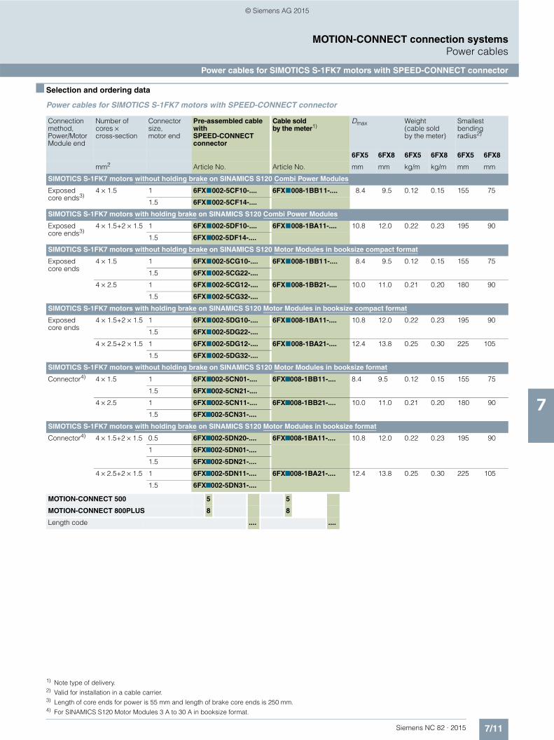
7/11Siemens NC 82 · 2015
MOTION-CONNECT connection systemsPower cables
Power cables for SIMOTICS S-1FK7 motors with SPEED-CONNECT connector
7
■ Selection and ordering data
Power cables for SIMOTICS S-1FK7 motors with SPEED-CONNECT connector
Connection method, Power/Motor Module end
Number of cores × cross-section
Connector size, motor end
Pre-assembled cable with SPEED-CONNECT connector
Cable sold by the meter1)
Dmax Weight(cable sold by the meter)
Smallest bending radius2)
6FX5 6FX8 6FX5 6FX8 6FX5 6FX8
mm2 Article No. Article No. mm mm kg/m kg/m mm mm
SIMOTICS S-1FK7 motors without holding brake on SINAMICS S120 Combi Power Modules
Exposed core ends3)
4 × 1.5 1 6FX7002-5CF10-.... 6FX7008-1BB11-.... 8.4 9.5 0.12 0.15 155 75
1.5 6FX7002-5CF14-....
SIMOTICS S-1FK7 motors with holding brake on SINAMICS S120 Combi Power Modules
Exposed core ends3)
4 × 1.5+2 × 1.5 1 6FX7002-5DF10-.... 6FX7008-1BA11-.... 10.8 12.0 0.22 0.23 195 90
1.5 6FX7002-5DF14-....
SIMOTICS S-1FK7 motors without holding brake on SINAMICS S120 Motor Modules in booksize compact format
Exposed core ends
4 × 1.5 1 6FX7002-5CG10-.... 6FX7008-1BB11-.... 8.4 9.5 0.12 0.15 155 75
1.5 6FX7002-5CG22-....
4 × 2.5 1 6FX7002-5CG12-.... 6FX7008-1BB21-.... 10.0 11.0 0.21 0.20 180 90
1.5 6FX7002-5CG32-....
SIMOTICS S-1FK7 motors with holding brake on SINAMICS S120 Motor Modules in booksize compact format
Exposed core ends
4 × 1.5+2 × 1.5 1 6FX7002-5DG10-.... 6FX7008-1BA11-.... 10.8 12.0 0.22 0.23 195 90
1.5 6FX7002-5DG22-....
4 × 2.5+2 × 1.5 1 6FX7002-5DG12-.... 6FX7008-1BA21-.... 12.4 13.8 0.25 0.30 225 105
1.5 6FX7002-5DG32-....
SIMOTICS S-1FK7 motors without holding brake on SINAMICS S120 Motor Modules in booksize format
Connector4) 4 × 1.5 1 6FX7002-5CN01-.... 6FX7008-1BB11-.... 8.4 9.5 0.12 0.15 155 75
1.5 6FX7002-5CN21-....
4 × 2.5 1 6FX7002-5CN11-.... 6FX7008-1BB21-.... 10.0 11.0 0.21 0.20 180 90
1.5 6FX7002-5CN31-....
SIMOTICS S-1FK7 motors with holding brake on SINAMICS S120 Motor Modules in booksize format
Connector4) 4 × 1.5+2 × 1.5 0.5 6FX7002-5DN20-.... 6FX7008-1BA11-.... 10.8 12.0 0.22 0.23 195 90
1 6FX7002-5DN01-....
1.5 6FX7002-5DN21-....
4 × 2.5+2 × 1.5 1 6FX7002-5DN11-.... 6FX7008-1BA21-.... 12.4 13.8 0.25 0.30 225 105
1.5 6FX7002-5DN31-....
MOTION-CONNECT 500 5 5
MOTION-CONNECT 800PLUS 8 8
Length code .... ....
1) Note type of delivery.2) Valid for installation in a cable carrier.3) Length of core ends for power is 55 mm and length of brake core ends is 250 mm.4) For SINAMICS S120 Motor Modules 3 A to 30 A in booksize format.
© Siemens AG 2015

7/12 Siemens NC 82 · 2015
MOTION-CONNECT connection systemsPower cables
Power cables for SIMOTICS M-1PH8 motors with terminal box
7
■ Selection and ordering data
Power cables for SIMOTICS M-1PH8 motors with terminal box
Motor Thread Number of cores × cross-section
Connection method Power/Motor Module end
Pre-assembled cable Cable sold by the meter1)
Dmax Weight(cable sold by the meter)
Smallest bending radius2)
6FX5 6FX8 6FX5 6FX8 6FX5 6FX8
Type mm2 Article No. Article No. mm mm kg/m kg/m mm mm
SIMOTICS M-1PH8 motors with terminal box on SINAMICS S120 Combi Power Modules
M-1PH808 M25 4 × 2.5 Exposed core ends3)
6FX7002-5CE02-.... 6FX8008-1BB21-.... 11.0 11.0 0.21 0.20 180 90
M-1PH810 M32 4 × 4 Exposed core ends3)
6FX7002-5CE04-.... 6FX8008-1BB31-.... 11.4 12.3 0.27 0.31 210 100
M-1PH813 M40 4 × 6 Exposed core ends3)
6FX7002-5CE06-.... 6FX8008-1BB41-.... 20.0 15.1 0.37 0.42 245 120
SIMOTICS M-1PH8 motors with terminal box on SINAMICS S120 Motor Modules in booksize compact format
M-1PH808 M25 4 × 2.5 Exposed core ends4)
6FX8002-5CR10-.... 6FX8008-1BB21-.... – 11.0 – 0.20 – 90
M-1PH810 M32 4 × 2.5 Exposed core ends4)
6FX8002-5CR11-.... 6FX8008-1BB21-.... – 11.0 – 0.20 – 90
SIMOTICS M-1PH8 motors with terminal box on SINAMICS S120 Motor Modules in booksize format
M-1PH808 M25 4 × 2.5 Connector5) 6FX8002-5CP10-.... 6FX8008-1BB21-.... – 11.0 – 0.20 – 90
M-1PH810 M32 4 × 2.5 Connector5) 6FX8002-5CP11-.... 6FX8008-1BB21-.... – 11.0 – 0.20 – 90
MOTION-CONNECT 500 5
MOTION-CONNECT 800PLUS 8 8
Length code .... ....
1) Note type of delivery.2) Valid for installation in a cable carrier.3) Length of core ends for power is 55 mm and length of brake core ends is 250 mm.4) Length of core ends: 300 mm. 4 M8 cable lugs and 4 M6 cable lugs are also included in the scope of supply of the cables.5) For SINAMICS S120 Motor Modules 3 A to 30 A in booksize format.
© Siemens AG 2015

7/13Siemens NC 82 · 2015
MOTION-CONNECT connection systemsSignal cables
7
■ Overview
MOTION-CONNECT DRIVE-CLiQ signal cable with IP20/IP67 connector
Signal cables are pre-assembled and are sold by the meter for the connection of a variety of components.
The following different types of cable are available:• DRIVE-CLiQ signal cables• MOTION-CONNECT DRIVE-CLiQ signal cables• MOTION-CONNECT pre-assembled signal cables
Type of delivery for pre-assembled signal cables
Pre-assembled signal cables are available in units of 10 cm.
The cables are supplied on reels up to 30 kg or 100 m. Above 30 kg or 100 m, cable drums are used instead of reels.
■ Application
DRIVE-CLiQ signal cables
DRIVE-CLiQ signal cables are used to connect components with DRIVE-CLiQ connections which have a separate or external 24 V DC power supply.
MOTION-CONNECT DRIVE-CLiQ signal cables
MOTION-CONNECT DRIVE-CLiQ signal cables with 24 V DC cores are used whenever components with DRIVE-CLiQ con-nections must meet high requirements such as mechanical stress and oil resistance, e.g. where a connection is made out-side the cabinet between Power Modules/Motor Modules and SIMOTICS S-1FK7/ SIMOTICS M-1PH8 motors with DRIVE-CLiQ interface.
MOTION-CONNECT pre-assembled signal cables
MOTION-CONNECT pre-assembled signal cables are used whenever motor encoders on motors without DRIVE-CLiQ inter-face are connected to Sensor Modules.
■ Technical specifications
Article No. 6FX2...-1DC..-.... 6FX5...-.DC..-.... 6FX8...-.DC..-....
Product name DRIVE-CLiQ signal cables DRIVE-CLiQ signal cables MOTION-CONNECT 500
DRIVE-CLiQ signal cables MOTION-CONNECT 800PLUS
Certificate of suitability
• cURus or UR/CSA1) UL STYLE 2502/CSA-N.210.2-M90 UL STYLE 2502/CSA-N.210.2-M90 UL STYLE 2502/CSA-N.210.2-M90
• RoHS conformity Yes Yes Yes
Rated voltage 30 V 30 V 30 V
Test voltage, rms 500 V 500 V 500 V
Operating temperature on the surface
• Fixed installation -20 … +80 °C -20 … +80 °C -50 … +80 °C
• Flexible installation – 0 … 60 °C -20 … +60 °C
Tensile stress, max.
• Fixed installation 45 N/mm2 80 N/mm2 50 N/mm2
• Flexible installation – 30 N/mm2 20 N/mm2
Smallest bending radius
• Fixed installation 50 mm 35 mm 35 mm
• Flexible installation – 125 mm 75 mm
1) The UR-CSA File No. is printed on the cable jacket.
© Siemens AG 2015
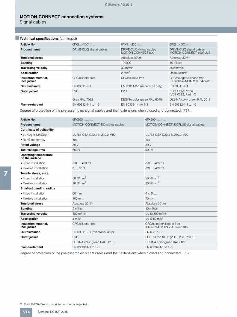
7/14 Siemens NC 82 · 2015
MOTION-CONNECT connection systemsSignal cables
7
■ Technical specifications (continued)
Degree of protection of the pre-assembled signal cables and their extensions when closed and connected: IP67.
Degree of protection of the pre-assembled signal cables and their extensions when closed and connected: IP67.
Article No. 6FX2...-1DC..-.... 6FX5...-.DC..-.... 6FX8...-.DC..-....
Product name DRIVE-CLiQ signal cables DRIVE-CLiQ signal cables MOTION-CONNECT 500
DRIVE-CLiQ signal cables MOTION-CONNECT 800PLUS
Torsional stress – Absolute 30°/m Absolute 30°/m
Bending – 100000 10 million
Traversing velocity – 30 m/min 300 m/min
Acceleration – 2 m/s2 Up to 50 m/s2
Insulation material, incl. jacket
CFC/silicone-free CFC/silicone-free CFC/halogen/silicone-freeIEC 60754-1/DIN VDE 0472-815
Oil resistance EN 60811-2-1 EN 60811-2-1 (mineral oil only) EN 60811-2-1
Outer jacket PVC PVC PUR, HD22.10 S2(VDE 0282, Part 10)
Gray RAL 7032 DESINA color green RAL 6018 DESINA color green RAL 6018
Flame-retardant EN 60332-1-1 to 1-3 EN 60332-1-1 to 1-3 EN 60332-1-1 to 1-3
Article No. 6FX500.-.....-.... 6FX800.-.....-....
Product name MOTION-CONNECT 500 signal cables MOTION-CONNECT 800PLUS signal cables
Certificate of suitability
• cURus or UR/CSA1) UL758-CSA-C22.2-N.210.2-M90 UL758-CSA-C22.2-N.210.2-M90
• RoHS conformity Yes Yes
Rated voltage 30 V 30 V
Test voltage, rms 500 V 500 V
Operating temperature on the surface
• Fixed installation -20 … +80 °C -50 … +80 °C
• Flexible installation 0 … 60 °C -20 … +60 °C
Tensile stress, max.
• Fixed installation 50 N/mm2 50 N/mm2
• Flexible installation 20 N/mm2 20 N/mm2
Smallest bending radius
• Fixed installation 60 mm 4 × Dmax
• Flexible installation 100 mm 70 mm
Torsional stress Absolute 30°/m Absolute 30°/m
Bending 2 million 10 million
Traversing velocity 180 m/min Up to 300 m/min
Acceleration 5 m/s2 Up to 50 m/s2
Insulation material, incl. jacket
CFC/silicone-free CFC/halogen/silicone-freeIEC 60754-1/DIN VDE 0472-815
Oil resistance EN 60811-2-1 (mineral oil only) EN 60811-2-1
Outer jacket PVC PUR, HD22.10 S2 (VDE 0282, Part 10)
DESINA color green RAL 6018 DESINA color green RAL 6018
Flame-retardant EN 60332-1-1 to 1-3 EN 60332-1-1 to 1-3
1) The UR-CSA File No. is printed on the cable jacket.
© Siemens AG 2015
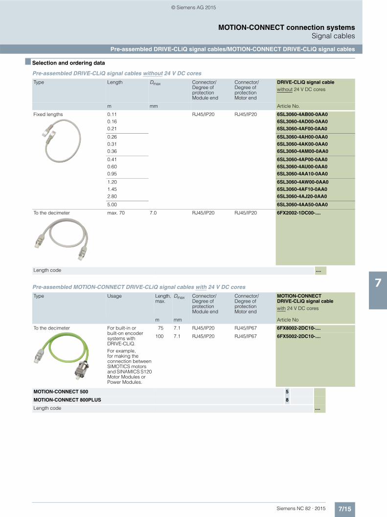
7/15Siemens NC 82 · 2015
MOTION-CONNECT connection systemsSignal cables
Pre-assembled DRIVE-CLiQ signal cables/MOTION-CONNECT DRIVE-CLiQ signal cables
7
■ Selection and ordering data
Pre-assembled DRIVE-CLiQ signal cables without 24 V DC cores
Pre-assembled MOTION-CONNECT DRIVE-CLiQ signal cables with 24 V DC cores
Type Length Dmax Connector/Degree of protection Module end
Connector/Degree of protection Motor end
DRIVE-CLiQ signal cablewithout 24 V DC cores
m mm Article No.
Fixed lengths 0.11 0.16 0.21
RJ45/IP20 RJ45/IP20 6SL3060-4AB00-0AA06SL3060-4AD00-0AA06SL3060-4AF00-0AA0
0.26 0.31 0.36
6SL3060-4AH00-0AA06SL3060-4AK00-0AA06SL3060-4AM00-0AA0
0.410.60 0.95
6SL3060-4AP00-0AA06SL3060-4AU00-0AA06SL3060-4AA10-0AA0
1.201.45 2.80
6SL3060-4AW00-0AA06SL3060-4AF10-0AA06SL3060-4AJ20-0AA0
5.00 6SL3060-4AA50-0AA0
To the decimeter max. 70 7.0 RJ45/IP20 RJ45/IP20 6FX2002-1DC00-....
Length code ....
Type Usage Length, max.
Dmax Connector/Degree of protection Module end
Connector/Degree of protection Motor end
MOTION-CONNECT DRIVE-CLiQ signal cablewith 24 V DC cores
m mm Article No
To the decimeter For built-in or built-on encoder systems with DRIVE-CLiQ.For example, for making the connection between SIMOTICS motors and SINAMICS S120 Motor Modules or Power Modules.
75 7.1 RJ45/IP20 RJ45/IP67 6FX8002-2DC10-....
100 7.1 RJ45/IP20 RJ45/IP67 6FX5002-2DC10-....
MOTION-CONNECT 500 5
MOTION-CONNECT 800PLUS 8
Length code ....
© Siemens AG 2015

7/16 Siemens NC 82 · 2015
MOTION-CONNECT connection systemsSignal cables
Signal cables for direct or external measuring systems with full-thread connector
7
■ Selection and ordering data
Pre-assembled signal cables for direct or external measuring systems with full-thread connector
The combinations of signal cable extensions shown are only provided by way of example.
The maximum specified cable length (basic cable and extensions) must not be exceeded. The total maximum length is reduced by 2 m for each interruption point.
Encoder system Connection via
Length, max.
Dmax Degree of protection Connector1)
Basic cable Extension
m mm Article No. Article No.
Absolute encoder with EnDat SMC20 100 9.8 IP20/IP67 6FX■002-2EQ10-.... 6FX■002-2EQ14-....
Absolute encoder with EnDat 6FX2001-5.E..
SMC20 100 9.2 IP20/IP67 6FX■002-2CH00-.... 6FX■002-2AD04-....
Absolute encoder with SSI 6FX2001-5.S.. 24 V DCClock-pulse rate 100 ... 250 kHz SMC30 100 9.3 IP20/IP67 6FX■002-2CC11-.... 6FX■002-2CB54-....
Incremental encoder sin/cos 1 Vpp 2048 S/R, with C and D tracks
SMC20 100 9.8 IP20/IP67 6FX■002-2CA31-…. 6FX■002-2CA34-....
Incremental encoder sin/cos 1 Vpp 256 and 512 S/R, without C and D tracks
SMC20 50 9.2 IP20/IP67 6FX8002-2CA80-.... 6FX■002-2CA34-....
HTL incremental encoder SMC30 3002) 9.3 IP20/IP67 6FX■002-2AH00-.... 6FX■002-2AH04-....
Incremental encoder sin/cos 1 Vpp without C and D tracks 6FX2001-3
SMC20 50 9.3 IP20/IP67 6FX■002-2CG00-.... 6FX■002-2CB54-....
HTL incremental encoder 24 V DC 6FX2001-4
SMC30 100 9.3 –/IP67 6FX5002-2CA12-.... –
TTL incremental encoder RS422 6FX2001-2
• 5 V DC SMC30 100 9.3 IP20/IP67 6FX■002-2CR00-.... 6FX■002-2CB54-....
• 24 V DC SMC30 100 9.3 IP20/IP67 6FX■002-2CD24-.... 6FX■002-2CB54-....
MOTION-CONNECT 500 5 5
MOTION-CONNECT 800PLUS 8 8
Length code .... ....
1) The specification of the degree of protection refers to the basic cable.2) Applicable to HTL encoders with bipolar signal evaluation or for evaluation of the difference signals A*, A and B*, B;
for HTL encoders with unipolar signal evaluation, the permissible cable length is reduced to 100 m.
© Siemens AG 2015
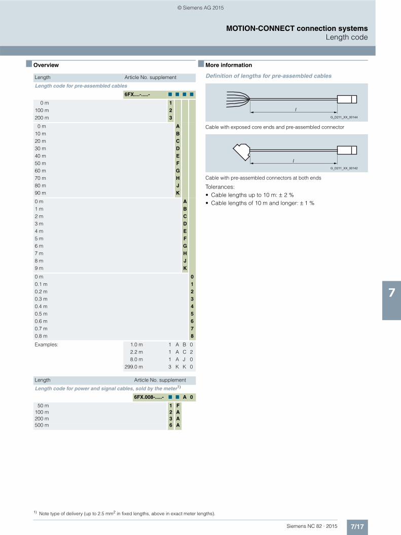
7/17Siemens NC 82 · 2015
MOTION-CONNECT connection systemsLength code
7
■ Overview ■ More information
Definition of lengths for pre-assembled cables
Cable with exposed core ends and pre-assembled connector
Cable with pre-assembled connectors at both ends
Tolerances:• Cable lengths up to 10 m: ± 2 %• Cable lengths of 10 m and longer: ± 1 %
Length Article No. supplement
Length code for pre-assembled cables
6FX....-.....- 7 7 7 7
0 m 100 m 200 m
123
0 m 10 m 20 m 30 m 40 m 50 m 60 m 70 m 80 m 90 m
ABCDEFGHJK
0 m 1 m 2 m 3 m 4 m 5 m 6 m 7 m 8 m 9 m
ABCDEFGHJK
0 m 0.1 m 0.2 m 0.3 m 0.4 m 0.5 m 0.6 m 0.7 m 0.8 m
012345678
Examples: 1.0 m2.2 m8.0 m
299.0 m
1113
AAAK
BCJK
0200
Length Article No. supplement
Length code for power and signal cables, sold by the meter1)
6FX.008-.....- 7 7 A 0
50 m 1 F100 m 2 A200 m 3 A500 m 6 A
1) Note type of delivery (up to 2.5 mm2 in fixed lengths, above in exact meter lengths).
l G_D211_XX_00144
l G_D211_XX_00142
© Siemens AG 2015
7/18 Siemens NC 82 · 2015
MOTION-CONNECT connection systems
Notes
7
© Siemens AG 2015

Siemens NC 82 · 2015
88/2 Services
8/2 On-site service
8/3 Documentation8/3 General documentation8/3 Specific documentation for
SINUMERIK 828D8/4 Specific documentation for
SINUMERIK 828D/SINAMICS S1208/4 Specific documentation for
SINAMICS S120 Combi8/4 General documentation for
SINUMERIK 828D
8/7 Training8/7 Training services8/8 SinuTrain for SINUMERIK Operate8/10 SINUMERIK 828D BASIC training case8/10 SINUMERIK 828D training case
8/11 Siemens Automation Cooperates with Education
8/11 Applicable practical know-how
8/13 Engineering software8/13 SIZER for Siemens Drives
engineering tool8/14 Drive Technology Configurator
8/15 Applications
Glossary SINUMERIK 828www.siemens.com/industrymall
Services and training
© Siemens AG 2015

8/2 Siemens NC 82 · 2015
8
Services and trainingServices
On-site service
■ Overview
Equipment package SINUMERIK 828D BASIC, SINAMICS S120 Combi and SIMOTICS M-1PH8 as well as SIMOTICS S-1FK7 motors
On-site service
For the SINUMERIK 828D BASIC and SINUMERIK 828D and the associated components1), you will receive a free on-site service contract for a period of 24 months from Siemens DF & PD.
The control is automatically registered on dispatch from the factory and the 24-month contract period begins. When arrival at the final destination or second commissioning is registered online (identSNAPSHOT) within 24 months following dispatch, the on-site service contract period is extended to 36 months.
On-site service includes:• Provision of servicing personnel• On-site diagnostics• Fault correction on site• Proof of fault correction
The fault correction is carried out by repairing and/or replacing faulty components.
■ Benefits
7 You benefit because the contract period for on-site service is extended to 36 months when final acceptance by your customer (second commissioning) is registered.
7 You can contractually extend the period for on-site service by an additional 6, 12, 24 or 36 months.
7 This contract extension is effective from expiry of the 36-month on-site service and must be purchased before it expires.
■ Selection and ordering data
■ More information
Further information about the conditions and the scope of the on-site service contract can be found at:
www.siemens.com/automation/oss
For further information about online registration with identSNAPSHOT, visit:
www.siemens.com/identsnapshot
1) Not applicable to complete motor spindles.
Description Article No.
Extension of on-site service 6FC8520-0RX00 - 7AA2
For SINUMERIK 828D BASIC and SINUMERIK 828D and the associated components from Siemens DF & PD on machine tools
• Contract extension by 6 months 0
• Contract extension by 12 months 1
• Contract extension by 24 months 2
• Contract extension by 36 months 3
© Siemens AG 2015

8/3Siemens NC 82 · 2015
8
Services and trainingDocumentation
General documentation/Specific documentation for SINUMERIK 828D
■ Overview
Comprehensive documentation is available for the SINUMERIK 828D BASIC and SINUMERIK 828D CNCs and the SINAMICS S120 Combi drive system, ranging from the Operating Manual, Programming Manual or Configuration Manual up to the Commissioning Manual.
Information is available in the following formats:• Paper version, printed copy• PDF file for downloading from the Internet
www.siemens.com/automation/support
You can find additional information on the Internet at:
www.siemens.com/motioncontrol/docu
■ Selection and ordering data
■ Selection and ordering data (continued)
Description Article No.
General documentation
DOConCDSINUMERIK 828D/840D sl SINAMICS S120SIMOTICS motorsSIMATICUser, manufacturer and service documentation on DVD-ROM Current version: 06/2015Languages:English, German
6FC5398-0AC10-1YA2
• Delivery of current version 6FC5298-0CD00-0YG0
• Update service 6FC5298-0CD00-0YG2
EMC Design Guidelines SIMOTICS, SIMOTION, SINAMICS, SINUMERIK
• Chinese Simplified 6FC5297-0AD30-0RP3
• German 6FC5297-0AD30-0AP3
• English 6FC5297-0AD30-0BP3
• French 6FC5297-0AD30-0DP3
• Italian 6FC5297-0AD30-0CP3
• Japanese 6FC5297-0AD30-0TP3
• Spanish 6FC5297-0AD30-0EP3
User Guide My SINUMERIK OperateThe useful reference guide at the machine
• German 6FC5095-0AA84-0AA2
• English 6FC5095-0AA84-0BA2
Description Article No.
Specific documentation for SINUMERIK 828D
PPU Manual SINUMERIK 828D
• Chinese Simplified 6FC5397-2DP40-5RA3
• Chinese Traditional 6FC5397-2DP40-5MA3
• German 6FC5397-2DP40-5AA3
• English 6FC5397-2DP40-5BA3
• Korean 6FC5397-2DP40-5LA3
Commissioning Manual SINUMERIK 828D Turning and Milling
• Chinese Simplified 6FC5397-3DP40-5RA3
• Chinese Traditional 6FC5397-3DP40-5MA3
• German 6FC5397-3DP40-5AA3
• English 6FC5397-3DP40-5BA3
• Korean 6FC5397-3DP40-5LA3
Commissioning Manual SINUMERIK 828D/840D sl SINUMERIK Integrate for Engineering Access MyMachine/ OPC UA
• German 6FC5397-1DP40-5AA3
• English 6FC5397-1DP40-5BA3
Service Manual SINUMERIK 828D
• Chinese Simplified 6FC5397-5DP40-5RA3
• Chinese Traditional 6FC5397-5DP40-5MA3
• German 6FC5397-5DP40-5AA3
• English 6FC5397-5DP40-5BA3
• Italian 6FC5397-5DP40-5CA3
• French 6FC5397-5DP40-5DA3
• Korean 6FC5397-5DP40-5LA3
• Portuguese 6FC5397-5DP40-5KA3
• Spanish 6FC5397-5DP20-5EA3
Parameter Manual Parameter Description SINUMERIK 828D
• Chinese Simplified 6FC5397-8DP40-5RA3
• German 6FC5397-8DP40-5AA3
• English 6FC5397-8DP40-5BA3
© Siemens AG 2015

8/4 Siemens NC 82 · 2015
8
■ Selection and ordering data (continued)
Services and trainingDocumentation
Specific documentation for SINUMERIK 828D/SINAMICS S120
Diagnostics Manual SINUMERIK 828D/SINAMICS S120
• Chinese Simplified 6FC5398-8BP40-5RA3
• Chinese Traditional 6FC5398-8BP40-5MA3
• German 6FC5398-8BP40-5AA3
• English 6FC5398-8BP40-5BA3
• Italian 6FC5398-8BP40-5CA3
• French 6FC5398-8BP40-5DA3
• Japanese 6FC5398-8BP40-5TA3
• Korean 6FC5398-8BP40-5LA3
• Polish 6FC5398-8BP40-5NA3
• Portuguese 6FC5398-8BP40-5KA3
• Russian 6FC5398-8BP40-5PA3
• Swedish 6FC5398-8BP40-5FA3
• Spanish 6FC5398-8BP40-5EA3
• Czech 6FC5398-8BP40-5UA3
• Hungarian 6FC5398-8BP40-5QA3
Parameter Manual Machine Data SINUMERIK 828D/SINAMICS S120
• Chinese Simplified 6FC5397-4DP40-5RA3
• German 6FC5397-4DP40-5AA3
• English 6FC5397-4DP40-5BA3
Parameter Manual NC variable and interface signals SINUMERIK 828D/SINAMICS S120
• Chinese Simplified 6FC5397-4DP41-1RA3
• German 6FC5397-4DP41-1AA3
• English 6FC5397-4DP41-1BA3
Specific documentation for SINAMICS S120 Combi
Manual SINAMICS S120 Combi
• Chinese Simplified 6SL3097-4AV00-0RP4
• Chinese Traditional 6SL3097-4AV00-0MP4
• German 6SL3097-4AV00-0AP4
• English 6SL3097-4AV00-0BP4
• Korean 6SL3097-4AV00-0LP4
• Portuguese 6SL3097-4AV00-0KP4
Description Article No. Description Article No.
General documentation for SINUMERIK 828D
Operating Manual SINUMERIK 840D sl/828D Turning
• Chinese Simplified 6FC5398-8CP40-5RA3
• Chinese Traditional 6FC5398-8CP40-5MA3
• Danish 6FC5398-8CP40-5GA3
• German 6FC5398-8CP40-5AA3
• English 6FC5398-8CP40-5BA3
• Italian 6FC5398-8CP40-5CA3
• French 6FC5398-8CP40-5DA3
• Finnish 6FC5398-8CP40-5HA3
• Japanese 6FC5398-8CP40-5TA3
• Korean 6FC5398-8CP40-5LA3
• Dutch 6FC5398-8CP40-5JA3
• Polish 6FC5398-8CP40-5NA3
• Portuguese 6FC5398-8CP40-5KA3
• Romanian 6FC5398-8CP40-5XC3
• Russian 6FC5398-8CP40-5PA3
• Swedish 6FC5398-8CP40-5FA3
• Slovakian 6FC5398-8CP40-5SA3
• Slovenian 6FC5398-8CP40-5WA3
• Spanish 6FC5398-8CP40-5EA3
• Thai 6FC5398-8CP40-5XE3
• Czech 6FC5398-8CP40-5UA3
• Turkish 6FC5398-8CP40-5VA3
• Hungarian 6FC5398-8CP40-5QA3
Operating Manual SINUMERIK 840D sl/828D Milling
• Chinese Simplified 6FC5398-7CP40-5RA3
• Chinese Traditional 6FC5398-7CP40-5MA3
• Danish 6FC5398-7CP40-5GA3
• German 6FC5398-7CP40-5AA3
• English 6FC5398-7CP40-5BA3
• Italian 6FC5398-7CP40-5CA3
• French 6FC5398-7CP40-5DA3
• Finnish 6FC5398-7CP40-5HA3
• Japanese 6FC5398-7CP40-5TA3
• Korean 6FC5398-7CP40-5LA3
• Dutch 6FC5398-7CP40-5JA3
• Polish 6FC5398-7CP40-5NA3
• Portuguese 6FC5398-7CP40-5KA3
• Romanian 6FC5398-7CP40-5XC3
• Russian 6FC5398-7CP40-5PA3
• Swedish 6FC5398-7CP40-5FA3
• Slovakian 6FC5398-7CP40-5SA3
• Slovenian 6FC5398-7CP40-5WA3
• Spanish 6FC5398-7CP40-5EA3
• Thai 6FC5398-7CP40-5XE3
• Czech 6FC5398-7CP40-5UA3
• Turkish 6FC5398-7CP40-5VA3
• Hungarian 6FC5398-7CP40-5QA3
Specific documentation for SINUMERIK 828D/SINAMICS S120/SINAMICS S120 Combi/General documentation for SINUMERIK 828D
© Siemens AG 2015

8/5Siemens NC 82 · 2015
8
■ Selection and ordering data (continued)
Services and trainingDocumentation
General documentation for SINUMERIK 828D
General documentation for SINUMERIK 828D (continued)Operating Manual SINUMERIK Operate Universal
• Chinese Simplified 6FC5398-6AP40-5RA3
• Chinese Traditional 6FC5398-6AP40-5MA3
• Danish 6FC5398-6AP40-5GA3
• German 6FC5398-6AP40-5AA3
• English 6FC5398-6AP40-5BA3
• Italian 6FC5398-6AP40-5CA3
• French 6FC5398-6AP40-5DA3
• Finnish 6FC5398-6AP40-5HA3
• Japanese 6FC5398-6AP40-5TA3
• Korean 6FC5398-6AP40-5LA3
• Dutch 6FC5398-6AP40-5JA3
• Polish 6FC5398-6AP40-5NA3
• Portuguese 6FC5398-6AP40-5KA3
• Romanian 6FC5398-6AP40-5XC3
• Russian 6FC5398-6AP40-5PA3
• Swedish 6FC5398-6AP40-5FA3
• Slovakian 6FC5398-6AP40-5SA3
• Slovenian 6FC5398-6AP40-5WA3
• Spanish 6FC5398-6AP40-5EA3
• Thai 6FC5398-6AP40-5XE3
• Czech 6FC5398-6AP40-5UA3
• Turkish 6FC5398-6AP40-5VA3
• Hungarian 6FC5398-6AP40-5QA3
Programming Manual Fundamentals SINUMERIK 840D sl/828D
• Chinese Simplified 6FC5398-1BP40-5RA3
• Chinese Traditional 6FC5398-1BP40-5MA3
• German 6FC5398-1BP40-5AA3
• English 6FC5398-1BP40-5BA3
• Italian 6FC5398-1BP40-5CA3
• French 6FC5398-1BP40-5DA3
• Japanese 6FC5398-1BP40-5TA3
• Korean 6FC5398-1BP40-5LA3
• Polish 6FC5398-1BP40-5NA3
• Portuguese 6FC5398-1BP40-5KA3
• Russian 6FC5398-1BP40-5PA3
• Swedish 6FC5398-1BP40-5FA3
• Spanish 6FC5398-1BP40-5EA3
• Czech 6FC5398-1BP40-5UA3
• Hungarian 6FC5398-1BP40-5QA3
Description Article No.
General documentation for SINUMERIK 828D (continued)Programming Manual Job Planning SINUMERIK 840D sl/828D
• Chinese Simplified 6FC5398-2BP40-5RA3
• Chinese Traditional 6FC5398-2BP40-5MA3
• German 6FC5398-2BP40-5AA3
• English 6FC5398-2BP40-5BA3
• Italian 6FC5398-2BP40-5CA3
• French 6FC5398-2BP40-5DA3
• Japanese 6FC5398-2BP40-5TA3
• Korean 6FC5398-2BP40-5LA3
• Polish 6FC5398-2BP40-5NA3
• Portuguese 6FC5398-2BP40-5KA3
• Russian 6FC5398-2BP40-5PA3
• Swedish 6FC5398-2BP40-5FA3
• Spanish 6FC5398-2BP40-5EA3
• Czech 6FC5398-2BP40-5UA3
• Hungarian 6FC5398-2BP40-5QA3
Programming Manual Measuring Cycles SINUMERIK 840D sl/828D
• Chinese Simplified 6FC5398-4BP40-5RA3
• Chinese Traditional 6FC5398-4BP40-5MA3
• German 6FC5398-4BP40-5AA3
• English 6FC5398-4BP40-5BA3
• Italian 6FC5398-4BP40-5CA3
• French 6FC5398-4BP40-5DA3
• Japanese 6FC5398-4BP40-5TA3
• Korean 6FC5398-4BP40-5LA3
• Polish 6FC5398-4BP40-5NA3
• Portuguese 6FC5398-4BP40-5KA3
• Russian 6FC5398-4BP40-5PA3
• Swedish 6FC5398-4BP40-5FA3
• Spanish 6FC5398-4BP40-5EA3
• Czech 6FC5398-4BP40-5UA3
• Hungarian 6FC5398-4BP40-5QA3
Description Article No.
© Siemens AG 2015
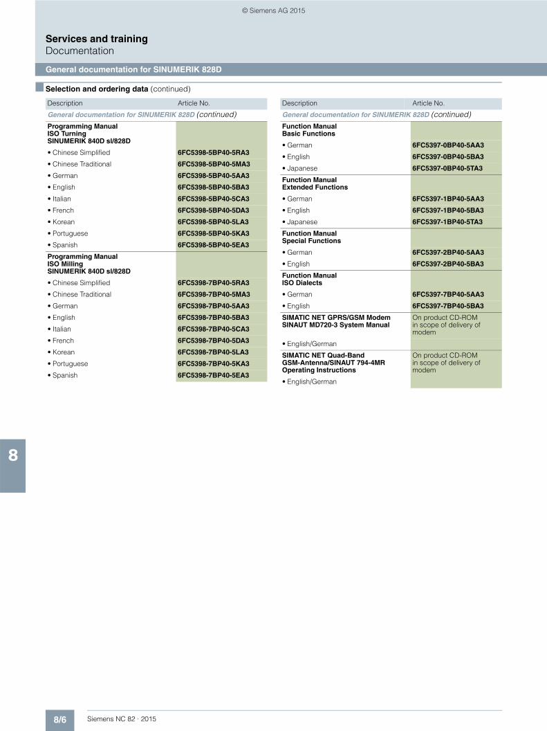
8/6 Siemens NC 82 · 2015
8
■ Selection and ordering data (continued)
Services and trainingDocumentation
General documentation for SINUMERIK 828D
General documentation for SINUMERIK 828D (continued)Programming Manual ISO Turning SINUMERIK 840D sl/828D
• Chinese Simplified 6FC5398-5BP40-5RA3
• Chinese Traditional 6FC5398-5BP40-5MA3
• German 6FC5398-5BP40-5AA3
• English 6FC5398-5BP40-5BA3
• Italian 6FC5398-5BP40-5CA3
• French 6FC5398-5BP40-5DA3
• Korean 6FC5398-5BP40-5LA3
• Portuguese 6FC5398-5BP40-5KA3
• Spanish 6FC5398-5BP40-5EA3
Programming Manual ISO Milling SINUMERIK 840D sl/828D
• Chinese Simplified 6FC5398-7BP40-5RA3
• Chinese Traditional 6FC5398-7BP40-5MA3
• German 6FC5398-7BP40-5AA3
• English 6FC5398-7BP40-5BA3
• Italian 6FC5398-7BP40-5CA3
• French 6FC5398-7BP40-5DA3
• Korean 6FC5398-7BP40-5LA3
• Portuguese 6FC5398-7BP40-5KA3
• Spanish 6FC5398-7BP40-5EA3
Description Article No.
General documentation for SINUMERIK 828D (continued)Function Manual Basic Functions
• German 6FC5397-0BP40-5AA3
• English 6FC5397-0BP40-5BA3
• Japanese 6FC5397-0BP40-5TA3
Function Manual Extended Functions
• German 6FC5397-1BP40-5AA3
• English 6FC5397-1BP40-5BA3
• Japanese 6FC5397-1BP40-5TA3
Function Manual Special Functions
• German 6FC5397-2BP40-5AA3
• English 6FC5397-2BP40-5BA3
Function Manual ISO Dialects
• German 6FC5397-7BP40-5AA3
• English 6FC5397-7BP40-5BA3
SIMATIC NET GPRS/GSM Modem SINAUT MD720-3 System Manual
On product CD-ROM in scope of delivery of modem
• English/German
SIMATIC NET Quad-Band GSM-Antenna/SINAUT 794-4MR Operating Instructions
On product CD-ROM in scope of delivery of modem
• English/German
Description Article No.
© Siemens AG 2015
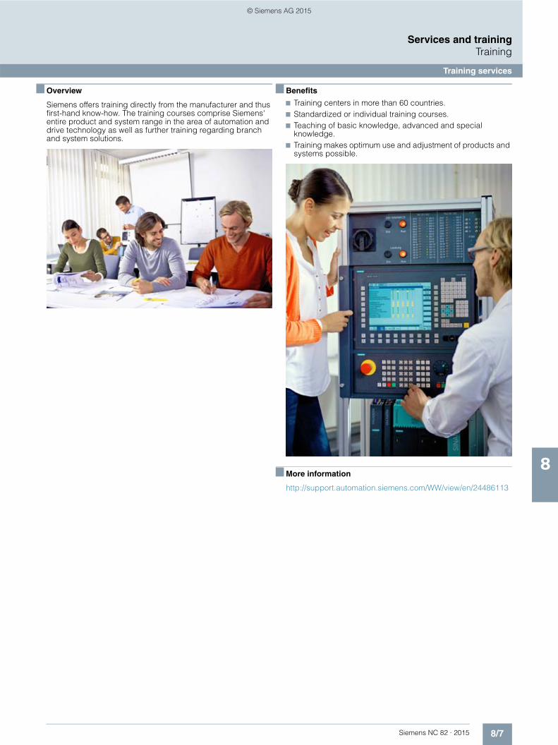
8/7Siemens NC 82 · 2015
8
Services and trainingTraining
Training services
■ Overview
Siemens offers training directly from the manufacturer and thus first-hand know-how. The training courses comprise Siemens' entire product and system range in the area of automation and drive technology as well as further training regarding branch and system solutions.
■ Benefits
7 Training centers in more than 60 countries. 7 Standardized or individual training courses. 7 Teaching of basic knowledge, advanced and special
knowledge. 7 Training makes optimum use and adjustment of products and
systems possible.
■ More information
http://support.automation.siemens.com/WW/view/en/24486113
© Siemens AG 2015

8/8 Siemens NC 82 · 2015
8
Services and trainingTraining
SinuTrain for SINUMERIK Operate
■ Overview
SinuTrain for SINUMERIK Operate is a PC-based CNC programming software package, based on the original CNC kernel.
SinuTrain for SINUMERIK Operate enables completely identical operator control and CNC programming as on SINUMERIK CNCs that are equipped with the graphical user interface SINUMERIK Operate.
■ Application
SinuTrain for SINUMERIK Operate can be used for the following applications:
In the work preparation• Higher machine availability through work preparation on the
CNC programming station and security through offline verification of the programs
• Operation and programming are identical 1:1 to that on the machine, so no new operating or programming knowledge is required.
• Increased productivity thanks to standardized program and tool management with SINUMERIK Integrate Manage MyPrograms and Manage MyTools
In the training1)
• Simple learning and professional training through preconfigured machines, and no additional hardware costs
• Learning as on the CNC, with additional tutorials and programming guides
• Perfectly tailored training packages directly from: www.siemens.com/sce
At the machine manufacturer• Adaptation of SinuTrain to the specific machine• The real machine and the machine-manufacturer-specific
SinuTrain delivered together to the end users• Another sales argument thanks to the CNC programming
station supplied
For the presentation• Present always and everywhere• Live demonstration of (new) SINUMERIK functions instead of
slides
■ Function
Programming, simulation and printing• DIN/ISO programming with programGUIDE• ShopTurn/ShopMill machining step programming• Multi-channel programming with programSYNC• Fully-fledged graphical CNC simulation• TCP/IP Ethernet networking with machines• Software machine control panel and operator panel• Print function for DIN/ISO and ShopTurn/ShopMill machining
step programs• DXF Reader
■ Integration
SinuTrain for SINUMERIK Operate Version 4.5 Edition 2 is based on SINUMERIK CNC software with software version 4.5 SP3, and can be used for:• SINUMERIK 828D BASIC• SINUMERIK 828D• SINUMERIK 840D sl
Requirements:
Hardware:• PC with 1.5 GHz processor (single core)• RAM: 1 GB• Hard disk: 3 GB of free memory space• DVD drive for installation from DVD• Graphics card: Minimum resolution 640 × 480 pixels• USB interface• Mouse, keyboard
Software:• Operating system
- Windows 7 Home Basic, Home Premium, Professional, Ultimate, Enterprise (32 bit/64 bit)
- Windows XP Professional SP3• Adobe Acrobat Reader
1) For schools and universities only, not for in-house vocational training
© Siemens AG 2015

8/9Siemens NC 82 · 2015
8
Services and trainingTraining
SinuTrain for SINUMERIK Operate
■ Selection and ordering data ■ More information
The first steps in working with SINUMERIK Operate can be learned quickly and easily through a web-based training program.
A trial version of SinuTrain for SINUMERIK Operate is available for download on the Internet.
You can find additional information on the Internet at:
www.siemens.com/cnc4you
Description Article No.
SinuTrain for SINUMERIK OperateVersion 4.5 Edition 2SINUMERIK 828D/828D BASIC SINUMERIK 840D sl with CNC software 4.5 SP3 Turning/milling/universal multi-channel capabilityOn DVD-ROM Languages: Chinese Simplified, English, French, German, Italian, Spanish
• Single-user license 6FC5870-4YC41-1YA0
• Upgrade for single-user license1)
6FC5870-4YC41-1YC0
• Classroom license (18) 6FC5870-8YC41-1YA0
• Upgrade for classroom license (18)1)
6FC5870-8YC41-1YC0
• SinuTrain trial version 60 days
6FC5870-0YC41-1YA0
Machine adaptation for SinuTrain for SINUMERIK Operate
• Machine adaptation by Siemens2)
6FC5088-4AA22-4AB1
• SinuTrain MCT (Machine Configuration Tool)
6FC5870-0CC41-1YA0
Training packages3)
• Trainer package 6 × single-user licenses 40 × student licenses
6FC5870-1TC41-0YA0
• Trainer package XL 1 × classroom license (18) 40 × student licenses
6FC5870-2TC41-0YA0
• 300 h student license 6FC5870-1YC41-1YA0
• Student package20 × 300 student licenses
6FC5870-1SC41-0YA0
1) With the upgrade license, you can upgrade an existing complete SinuTrain, SinuTrain ShopTurn or SinuTrain ShopMill to SinuTrain for SINUMERIK Operate V4.5. Prerequisite for the upgrade license is an existing, valid license key for SinuTrain versions 6.3, 7.3, 7.5, 2.6 or 4.4, this excludes SinuTrain Trial/Promotion and SinuTrain Trial BASIC.
2) Services for machine adaptation: You provide a complete file for CNC series commissioning archive by email You will then receive a file for importing into SinuTrain by email. For more information, please contact your Siemens branch.
3) For schools and universities only, not for in-house vocational training departments: www.siemens.com/sce
© Siemens AG 2015

8/10 Siemens NC 82 · 2015
8
Services and trainingTraining
SINUMERIK 828D BASIC training case SINUMERIK 828D training case
■ Overview
SINUMERIK 828D BASIC training case
The SINUMERIK 828D BASIC training case is used for the realistic practice of operating, programming, commissioning and service tasks.
■ Design
The SINUMERIK 828D BASIC training case contains:• SINUMERIK 828D BASIC PPU 241.3
including system software and software options• SINUMERIK MCP 483 PN machine control panel• SINUMERIK PP 72/48D 2/2A PN I/O module• SINAUT MD720-3 GSM/GPRS modem including antenna• SITOP power supply 24 V/10 A• Industrial Ethernet Switch SCALANCE XB005 unmanaged
The SINUMERIK 828D BASIC training case is designed for table set-up and is supplied in a PELI protector case with integrated rigid foam inlay. The extendable handle and the rollers in the base make the case easy to transport.
■ Technical specifications
■ Selection and ordering data
■ Overview
SINUMERIK 828D training case
The SINUMERIK 828D training case is used for the realistic practice of operating, programming, installation and service tasks.
■ Design
The SINUMERIK 828D training case contains:• SINUMERIK 828D PPU 281.3
including system software and software options• SINUMERIK MCP 483 PN machine control panel• SINUMERIK PP 72/48D PN I/O module• SINAUT MD720-3 GSM/GPRS modem including antenna• SITOP 24 V/10 A power supply• Industrial Ethernet Switch SCALANCE XB005 unmanaged
The SINUMERIK 828D training case is designed for table set-up and is supplied in a PELI protector case with integrated rigid foam inlay. The extendable handle and the rollers in the base make the case easy to transport.
■ Technical specifications
■ Selection and ordering data
Article number 6AG1067-1AA24-0AA0
Product designation SINUMERIK 828D BASIC training case
Supply voltage AC 230 V
Degree of protection IP00
Ambient temperature, during
• storage -20 ... +60 °C
• transport -20 ... +60 °C
• operation 5 ... 40 °C
Width 650 mm
Height 500 mm
Depth 250 mm
Net weight 30 kg
Description Article No.
SINUMERIK 828D BASICtraining case
6AG1067-1AA24-0AA0
Article number 6AG1067-1AA13-0AA0
Product designation SINUMERIK 828D training case
Supply voltage AC 230 V
Degree of protection IP00
Ambient temperature, during
• storage -20 ... +60 °C
• transport -20 ... +60 °C
• operation 5 ... 40 °C
Width 650 mm
Height 500 mm
Depth 250 mm
Net weight 30 kg
Description Article No.
SINUMERIK 828D training case
6AG1067-1AA13-0AA0
© Siemens AG 2015

8/11Siemens NC 82 · 2015
8
Services and trainingSiemens Automation Cooperates with Education
Applicable practical know-how
■ Comprehensive teaching support for educational institutions
Siemens Automation Cooperates with Education (SCE)
SCE offers a global system for sustained support of technical skills. SCE supports educational institutions in their teaching assignment in the industrial automation sector and offers added value in the form of partnerships, technical expertise, and know-how. As the technological leader, our comprehensive range of services can support you in the transfer of industrial knowledge.
Our services at a glance• Training curriculums for your lessons• Trainer packages for hands-on learning• Courses convey up-to-date, specialist knowledge• Support for your projects/textbooks• Complete didactic solutions from our partners for your lessons• Personal contact for individual support
Training curriculums for your lessons
Use our profound industrial know-how for practice-oriented and individual design of your course. We offer you more than 90 didactically prepared training documents on the topics of automation and drives technology free of charge. These materi-als are perfectly matched to your curricula and syllabuses, and optimally suited for use with our trainer packages. This takes into account all aspects of a modern industrial solution: installation, configuration, programming, and commissioning. All documents, including projects, can be individually matched to your specific requirements.
Particular highlight: the new SIMATIC PCS 7 curriculums and trainer packages. Using plant simulation, you can pass on basic, practice-oriented PCS 7 knowledge at universities within about 60 hours (= 1 semester).
www.siemens.com/sce/documents
Trainer packages for hands-on learning
Our SCE trainer packages offer a specific combination of origi-nal industrial components which are perfectly matched to your requirements and can be conveniently used in your course. These price reduced bundles available exclusively to schools include innovative and flexible hardware and software pack-ages. We currently offer more than 80 SCE trainer packages including related equipment. These cover both the factory and process automation sectors. You can use them to impart the complete course contents on industrial automation at a very low cost.
Trainer packages are available for:• Introduction to automation technology with LOGO! compact
controller and SIMATIC S7-1200• PLC engineering with SIMATIC S7 hardware and STEP 7
software• Operator control and monitoring with SIMATIC HMI• Industrial networking over bus systems with SIMATIC NET• Sensor systems with VISION, RFID, and SIWAREX• Process automation with SIMATIC PCS 7• Networked drive and motion technologies with SINAMICS and
SIMOTION• CNC programming with SinuTrain
Important ordering notes:
Only the following institutions are authorized to obtain trainer packages: vocational schools, Colleges and Universities, in-house vocational training departments, non commercial research institutions and non commercial training departments.
To purchase a trainer package, you require a specific end-use certificate, which you can obtain from your regional sales office.
www.siemens.com/sce/tp
© Siemens AG 2015
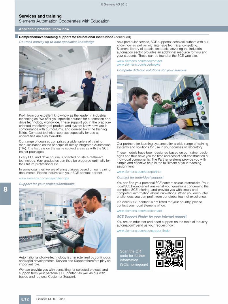
8/12 Siemens NC 82 · 2015
8
■ Comprehensive teaching support for educational institutions (continued)
Services and trainingSiemens Automation Cooperates with Education
Applicable practical know-how
Courses convey up-to-date specialist knowledge
Profit from our excellent know-how as the leader in industrial technologies. We offer you specific courses for automation and drive technology worldwide. These support you in the practice-oriented transferring of product and system know-how, are in conformance with curriculums, and derived from the training fields. Compact technical courses especially for use at universities are also available.
Our range of courses comprises a wide variety of training modules based on the principle of Totally Integrated Automation (TIA). The focus is on the same subject areas as with the SCE trainer packages.
Every PLC and drive course is oriented on state-of-the-art technology. Your graduates can thus be prepared optimally for their future professional life.
In some countries we are offering classes based on our training documents. Please inquire with your SCE contact partner.
www.siemens.com/sce/workshops
Support for your projects/textbooks
Automation and drive technology is characterized by continuous and rapid developments. Service and Support therefore play an important role.
We can provide you with consulting for selected projects and support from your personal SCE contact as well as our web based and regional Customer Support.
As a particular service, SCE supports technical authors with our know-how as well as with intensive technical consulting. Siemens library of special textbooks covering the industrial automation sector provides an additional resource for you and your students. These can be found at the SCE web site.
www.siemens.com/sce/contact www.siemens.com/sce/books
Complete didactic solutions for your lessons
Our partners for learning systems offer a wide range of training systems and solutions for use in your courses or laboratory.
These models have been designed based on our trainer pack-ages and thus save you the time and cost of self-construction of individual components. The Partner systems provide you with simple and effective help in the fulfillment of your teaching assignment.
www.siemens.com/sce/partner
Contact for individual support
You can find your personal SCE contact on our Internet site. Your local SCE Promoter will answer all your questions concerning the complete SCE offering, and provide you with timely and competent information about innovations. When you encounter challenges, you can profit from our global team of excellence.
If a direct SCE contact is not listed for your country, please contact your local Siemens office.
www.siemens.com/sce/contact
SCE Support Finder for your Internet request
You are an educator and need support on the topic of industry automation? Send us your request now:
www.siemens.com/sce/supportfinder
© Siemens AG 2015
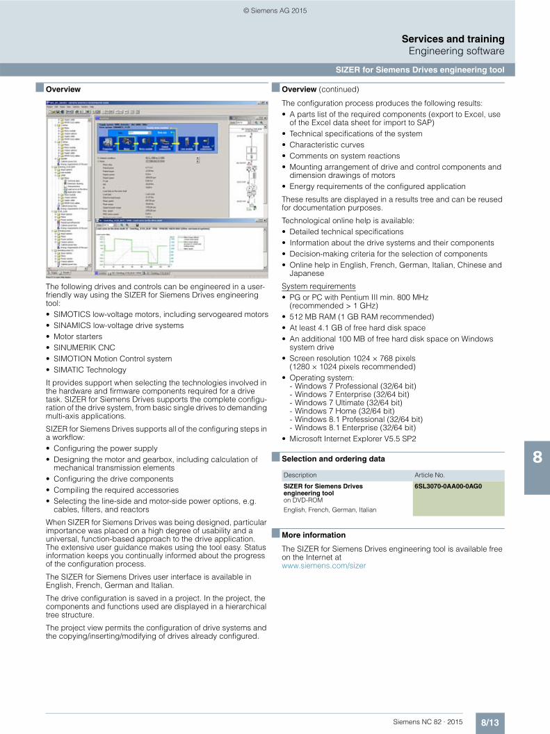
8/13Siemens NC 82 · 2015
8
Services and trainingEngineering software
SIZER for Siemens Drives engineering tool
■ Overview
The following drives and controls can be engineered in a user-friendly way using the SIZER for Siemens Drives engineering tool:• SIMOTICS low-voltage motors, including servogeared motors• SINAMICS low-voltage drive systems• Motor starters• SINUMERIK CNC• SIMOTION Motion Control system• SIMATIC Technology
It provides support when selecting the technologies involved in the hardware and firmware components required for a drive task. SIZER for Siemens Drives supports the complete configu-ration of the drive system, from basic single drives to demanding multi-axis applications.
SIZER for Siemens Drives supports all of the configuring steps in a workflow:• Configuring the power supply• Designing the motor and gearbox, including calculation of
mechanical transmission elements• Configuring the drive components• Compiling the required accessories• Selecting the line-side and motor-side power options, e.g.
cables, filters, and reactors
When SIZER for Siemens Drives was being designed, particular importance was placed on a high degree of usability and a universal, function-based approach to the drive application. The extensive user guidance makes using the tool easy. Status information keeps you continually informed about the progress of the configuration process.
The SIZER for Siemens Drives user interface is available in English, French, German and Italian.
The drive configuration is saved in a project. In the project, the components and functions used are displayed in a hierarchical tree structure.
The project view permits the configuration of drive systems and the copying/inserting/modifying of drives already configured.
■ Overview (continued)
The configuration process produces the following results:• A parts list of the required components (export to Excel, use
of the Excel data sheet for import to SAP)• Technical specifications of the system• Characteristic curves• Comments on system reactions• Mounting arrangement of drive and control components and
dimension drawings of motors• Energy requirements of the configured application
These results are displayed in a results tree and can be reused for documentation purposes.
Technological online help is available:• Detailed technical specifications• Information about the drive systems and their components• Decision-making criteria for the selection of components• Online help in English, French, German, Italian, Chinese and
Japanese
System requirements• PG or PC with Pentium III min. 800 MHz
(recommended > 1 GHz)• 512 MB RAM (1 GB RAM recommended)• At least 4.1 GB of free hard disk space• An additional 100 MB of free hard disk space on Windows
system drive• Screen resolution 1024 × 768 pixels
(1280 × 1024 pixels recommended)• Operating system:
- Windows 7 Professional (32/64 bit)- Windows 7 Enterprise (32/64 bit)- Windows 7 Ultimate (32/64 bit)- Windows 7 Home (32/64 bit)- Windows 8.1 Professional (32/64 bit)- Windows 8.1 Enterprise (32/64 bit)
• Microsoft Internet Explorer V5.5 SP2
■ Selection and ordering data
■ More information
The SIZER for Siemens Drives engineering tool is available free on the Internet atwww.siemens.com/sizer
Description Article No.
SIZER for Siemens Drives engineering toolon DVD-ROM
English, French, German, Italian
6SL3070-0AA00-0AG0
© Siemens AG 2015

8/14 Siemens NC 82 · 2015
8
Services and trainingEngineering software
Drive Technology Configurator
■ Overview
The Drive Technology Configurator (DT Configurator) helps you to configure the optimum drive technology products for your application – starting with gear units, motors, inverters and the associated options and components and ending with control-lers, software licenses and connection technology. Whether with little or detailed knowledge of products: You can easily, quickly and efficiently configure your particular drive using product group preselectors, targeted navigation through selection menus or by entering article numbers directly to select the products.
In addition to all this, comprehensive documentation comprising technical data sheets, 2D/3D dimensional drawings, operating instructions, certificates etc. can be selected in the DT Configurator. The products that you select can be directly ordered by transferring a parts list to the shopping cart of the Industry Mall.
Drive Technology Configurator for efficient drive configuration with the following functions:• Quick, efficient configuration of drive products and associated
components – gear units, motors, inverters, controllers, connection technology
• Configuration of drive systems for pump, fan and compressor applications from 1 kW to 2.6 MW
• Retrievable documentation for configured products and components, such as - Data sheets in up to 7 languages in PDF or RTF formats- 2D/3D dimensional drawings in various formats- Terminal box diagram and terminal connection diagram- Operating instructions- Certificates- Starting calculation for SIMOTICS motors- EPLAN macros
• Support for retrofit projects in conjunction with Spares On Web (www.siemens.com/sow)
• Products can be ordered directly through the Siemens Industry Mall
Access to the Drive Technology Configurator
The Drive Technology Configurator can be accessed without registration and login:
www.siemens.com/dt-configurator
■ Selection and ordering data
■ More information
Online access to the Drive Technology Configurator
More information about the Drive Technology Configurator is available on the Internet at www.siemens.com/dtconfigurator
Offline access to the Drive Technology Configurator in the Interactive Catalog CA 01
In addition, the Drive Technology Configurator is also included in the interactive catalog CA 01 on DVD-ROM – the offline version of the Siemens Industry Mall.The Interactive Catalog CA 01 can be ordered from the relevant Siemens sales office or via the Internet:
www.siemens.com/automation/CA01
Description Article No.
Interactive catalog CA 01
on DVD-ROMincl. Drive Technology Configurator
Language: English
E86060-D4001-A510-D4-7600
© Siemens AG 2015

8/15Siemens NC 82 · 2015
8
Services and trainingApplications
■ Overview
Application examples
Descriptions of real, functioning and sector-neutral solutions, comprising a solution path, performance/power data, configuring instructions and the tested program code.
■ Benefits
The application examples show you solutions for typical automation tasks as example. You can use this as a suggestion or basis for your own solutions.
■ More information
You can find application examples on the Internet at:
www.siemens.com/automation/support
Or please contact your Siemens representative.
© Siemens AG 2015

8/16 Siemens NC 82 · 2015
8
Services and training
Notes
© Siemens AG 2015
Siemens NC 82 · 2015
99/2 Introduction
9/3 EMUGE-FRANKEN GmbH & Co. KG Precision tools
9/4 Hofmann GmbH & Co. KG AB 9000 ring balancing system
9/5 MARPOSS S.p.A. Laser Tool Setter
9/6 MCU GmbH & Co. KG Toolinspect II
9/7 PROMETEC GmbH PROSINPLUS
9/8 Renishaw GmbH Non-contact tool inspection
SINUMERIK Solution Partners
© Siemens AG 2015
9/2 Siemens NC 82 · 2015
9
SINUMERIK Solution Partners
Introduction
■ Overview
The SINUMERIK Solution Partners supplement the open SINUMERIK CNCs with their own solutions.
The solutions of the SINUMERIK Solution Partners are certified and therefore offer a high degree of reliability and compatibility in productive use with the SINUMERIK CNC in production.
SINUMERIK Solution Partners assume responsibility for their own solutions, products and services.
■ More information
The systems supplied by our Solution Partners are in many cases available for earlier SINUMERIK software versions and can be installed retrospectively. For further information, please contact the Solution Partner directly.
More information is available on the Internet at:
www.siemens.com/solution-partner
© Siemens AG 2015

9/3Siemens NC 82 · 2015
9
SINUMERIK Solution Partners
EMUGE-FRANKEN GmbH & Co. KG – Precision tools
■ Overview
Precision tools that save time and money
EMUGE-FRANKEN is a group of companies that offers state-of-the-art thread cutting, testing, clamping and milling technology – and has done so for over 90 years.
Our products:• Taps• Thread gauges• Thread cutters• Tapping chucks• Twist drills• HSS milling cutters• VHM milling cutters• Threading dies• Workpiece clamping
The broadly based customer sectors include, alongside the automotive industry, also the power plant and aeronautical industry, as well as mechanical and plant engineering. 50 % of the products are exported throughout the world.
Over 1000 employees in Lauf and Rückersdorf, Germany, as well as 300 employees worldwide are responsible for the exten-sive range of products and services offered. All activities are targeted at optimizing manufacturing processes, to show the customer solutions that will save time and money.
With a range of tools that comprises more than 110000 items, EMUGE-FRANKEN covers a broad spectrum in order to satisfy the growing requirements of the market. Apart from the ex-stock standard product range, special tools are developed in cooperation with customers which are tuned to the respective process and to the machine requirements.
■ Overview (continued)
A team of experts provides the following services for the products offered by EMUGE-FRANKEN:• Worldwide hotline advice and support for the solution of
technical problems• Cooperation for planning overall concepts and suggestions
for optimizing the production procedure at the customer's site• Trials are implemented free-of-charge with customer-specific
materials in a purpose-built test area for optimum tool selection and recommendation
• Development and construction of customer-specific special tools
• Deployment of service technicians• Provision of product-related training and seminars worldwide
■ More information
EMUGE-Werk Richard Glimpel GmbH & Co. KG Factory for precision tools
Nürnberger Straße 96-100 91207 LAUF A. D. PEGNITZ GERMANY
Tel.: +49 9123 186-0 E-mail: [email protected]: www.emuge-franken.com
FRANKEN GmbH & Co. KG Factory for precision tools
Frankenstraße 7/9a 90607 RÜCKERSDORF GERMANY
Tel.: +49 911 9575-5 E-mail: [email protected]: www.emuge-franken.com
© Siemens AG 2015
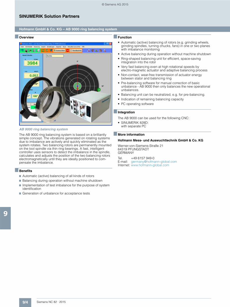
9/4 Siemens NC 82 · 2015
9
SINUMERIK Solution Partners
Hofmann GmbH & Co. KG – AB 9000 ring balancing system
■ Overview
AB 9000 ring balancing system
The AB 9000 ring balancing system is based on a brilliantly simple concept. The vibrations generated on rotating systems due to imbalance are actively and quickly eliminated as the system rotates. Two balancing rotors are permanently mounted on the tool spindle via thin ring bearings. A fast, intelligent controller uses sensors to detect the imbalance in the spindle, calculates and adjusts the position of the two balancing rotors electromagnetically until they are ideally positioned to com-pensate the imbalance.
■ Benefits
7 Automatic (active) balancing of all kinds of rotors7 Balancing during operation without machine shutdown7 Implementation of test imbalance for the purpose of system
identification7 Generation of unbalance for acceptance tests
■ Function
• Automatic (active) balancing of rotors (e.g. grinding wheels, grinding spindles, turning chucks, fans) in one or two planes with imbalance monitoring
• Active balancing during operation without machine shutdown• Ring-shaped balancing unit for efficient, space-saving
integration into the rotor• Very fast balancing even at high rotational speeds by
electro-magnetic actuator and adaptive balancing process• Non-contact, wear-free transmission of actuator energy
between stator and balancing ring• Pre-balancing software for manual correction of basic
unbalance - AB 9000 then only balances the new operational unbalances.
• Balancing unit can be neutralized, e.g. for pre-balancing.• Indication of remaining balancing capacity• PC operating software
■ Integration
The AB 9000 can be used for the following CNC:• SINUMERIK 828D:
with separate PC
■ More information
Hofmann Mess- und Auswuchttechnik GmbH & Co. KG
Werner-von-Siemens-Straße 21 64319 PFUNGSTADT GERMANY
Tel. +49 6157 949-0 E-mail: [email protected]: www.hofmann-global.com
© Siemens AG 2015

9/5Siemens NC 82 · 2015
9
SINUMERIK Solution Partners
MARPOSS S.p.A. – Laser Tool Setter
■ Overview
Laser Tool Setter – Automatic non-contact tool setting, part probing, machine and tool monitoring on machine tools
Marposs provides measuring cycles for part probing and tool setting which work in synergy with Marposs Probing Systems. The specific user interface makes programming easy.
All the necessary measurements can be performed on the part and on the tool for rapid setup of the machine. High-speed monitoring of the part, before and after the machining cycle as well as continuous monitoring of the machining conditions, can be performed by Marposs Probing and Monitoring Systems.
■ Benefits
7 Fast, automatic and precise workpiece setup7 Tool presetting in machine condition to compensate axes
thermal drift7 Tool and process verification to keep high production quality7 Part inspection on machine to avoid repositioning
■ Function
Tool measurements with Mida laser:• Length and diameter of the tool • Axial breakage• Cutters integrity • Cutters radius• Compensation of the thermal drift of the machine axes
Part measurements with Mida spindle probes:• Part positioning • Measuring of drilled holes, pins, pockets and shoulders • Single surface measurement • Measuring the internal and external cross-arm
Machine and tool monitoring with MMS:• Performance (tool breakage and wear)• Force (cutting force optimization)• Vibrations (machine condition and tool unbalancing)• Temperature (overheating of bearings) • Displacement (spindle growth)
■ Integration
Laser Tool Setter and probing systems can be used for the following CNC:• SINUMERIK 828D
■ More information
MARPOSS S.p.A.
Via Saliceto 13 40010 BENTIVOGLIO (BO) ITALY
Tel.: +39 051 899534E-mail: [email protected]: www.marposs.com
© Siemens AG 2015
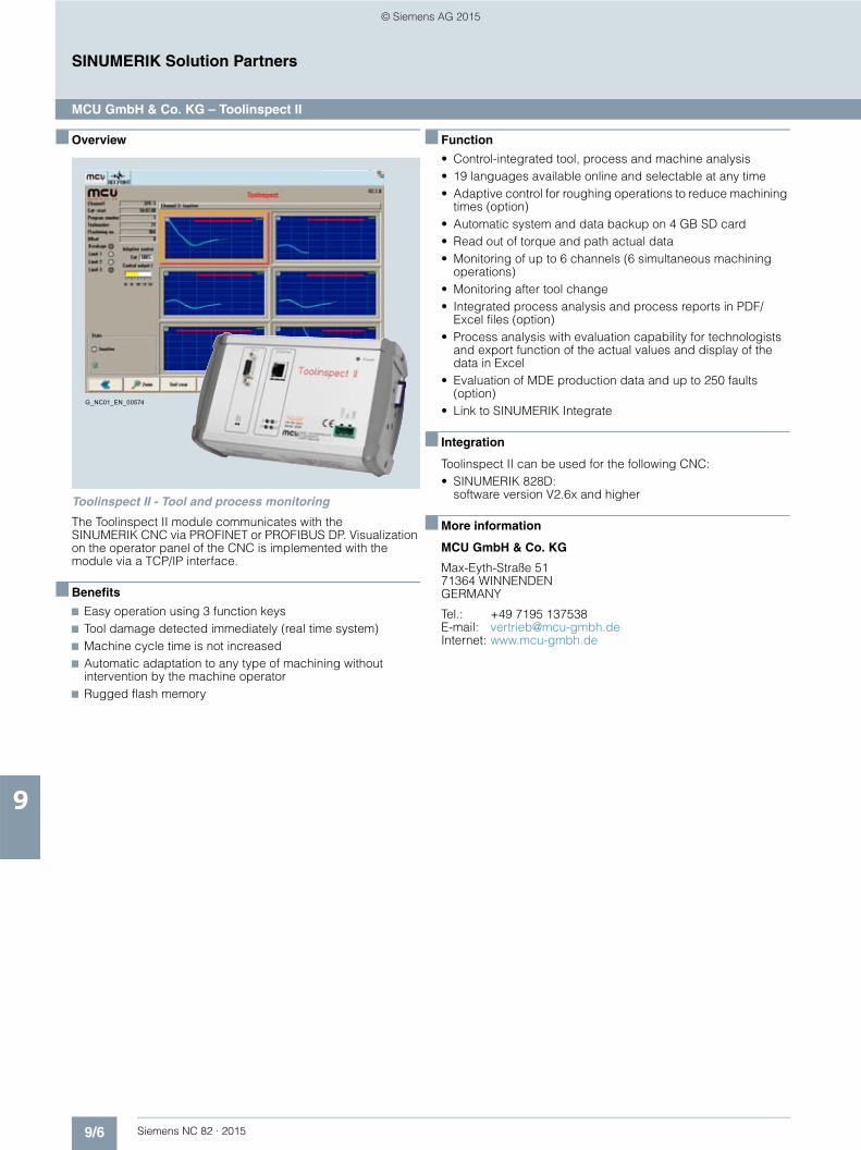
9/6 Siemens NC 82 · 2015
9
SINUMERIK Solution Partners
MCU GmbH & Co. KG – Toolinspect II
■ Overview
Toolinspect II - Tool and process monitoring
The Toolinspect II module communicates with the SINUMERIK CNC via PROFINET or PROFIBUS DP. Visualization on the operator panel of the CNC is implemented with the module via a TCP/IP interface.
■ Benefits
7 Easy operation using 3 function keys7 Tool damage detected immediately (real time system)7 Machine cycle time is not increased7 Automatic adaptation to any type of machining without
intervention by the machine operator7 Rugged flash memory
■ Function
• Control-integrated tool, process and machine analysis• 19 languages available online and selectable at any time• Adaptive control for roughing operations to reduce machining
times (option)• Automatic system and data backup on 4 GB SD card• Read out of torque and path actual data• Monitoring of up to 6 channels (6 simultaneous machining
operations)• Monitoring after tool change• Integrated process analysis and process reports in PDF/
Excel files (option)• Process analysis with evaluation capability for technologists
and export function of the actual values and display of the data in Excel
• Evaluation of MDE production data and up to 250 faults (option)
• Link to SINUMERIK Integrate
■ Integration
Toolinspect II can be used for the following CNC:• SINUMERIK 828D:
software version V2.6x and higher
■ More information
MCU GmbH & Co. KG
Max-Eyth-Straße 5171364 WINNENDEN GERMANY
Tel.: +49 7195 137538 E-mail: [email protected]: www.mcu-gmbh.de
G_NC01_EN_00574
© Siemens AG 2015
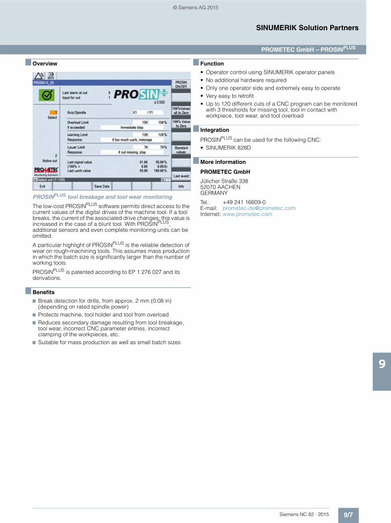
9/7Siemens NC 82 · 2015
9
SINUMERIK Solution Partners
■ Overview
PROSINPLUS tool breakage and tool wear monitoring
The low-cost PROSINPLUS software permits direct access to the current values of the digital drives of the machine tool. If a tool breaks, the current of the associated drive changes; this value is increased in the case of a blunt tool. With PROSINPLUS, additional sensors and even complete monitoring units can be omitted.
A particular highlight of PROSINPLUS is the reliable detection of wear on rough-machining tools. This assumes mass production in which the batch size is significantly larger than the number of working tools.
PROSINPLUS is patented according to EP 1 276 027 and its derivations.
■ Benefits
7 Break detection for drills, from approx. 2 mm (0.08 in) (depending on rated spindle power)
7 Protects machine, tool holder and tool from overload7 Reduces secondary damage resulting from tool breakage,
tool wear, incorrect CNC parameter entries, incorrect clamping of the workpieces, etc.
7 Suitable for mass production as well as small batch sizes
■ Function
• Operator control using SINUMERIK operator panels• No additional hardware required• Only one operator side and extremely easy to operate• Very easy to retrofit• Up to 120 different cuts of a CNC program can be monitored
with 3 thresholds for missing tool, tool in contact with workpiece, tool wear, and tool overload
■ Integration
PROSINPLUS can be used for the following CNC:• SINUMERIK 828D
■ More information
PROMETEC GmbH
Jülicher Straße 338 52070 AACHEN GERMANY
Tel.: +49 241 16609-0 E-mail: [email protected]: www.prometec.com
PROMETEC GmbH – PROSINPLUS
© Siemens AG 2015
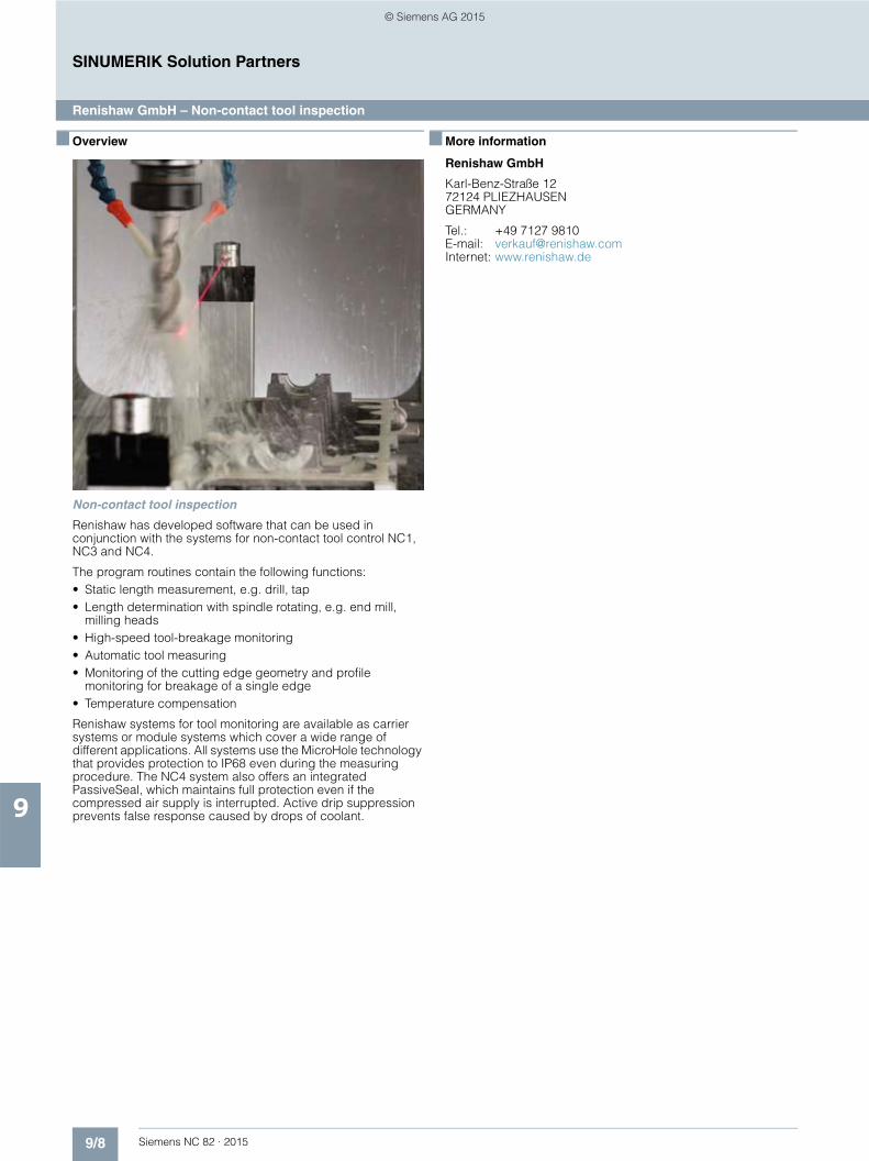
9/8 Siemens NC 82 · 2015
9
SINUMERIK Solution Partners
Renishaw GmbH – Non-contact tool inspection
■ Overview
Non-contact tool inspection
Renishaw has developed software that can be used in conjunction with the systems for non-contact tool control NC1, NC3 and NC4.
The program routines contain the following functions:• Static length measurement, e.g. drill, tap• Length determination with spindle rotating, e.g. end mill,
milling heads• High-speed tool-breakage monitoring• Automatic tool measuring• Monitoring of the cutting edge geometry and profile
monitoring for breakage of a single edge• Temperature compensation
Renishaw systems for tool monitoring are available as carrier systems or module systems which cover a wide range of different applications. All systems use the MicroHole technology that provides protection to IP68 even during the measuring procedure. The NC4 system also offers an integrated PassiveSeal, which maintains full protection even if the compressed air supply is interrupted. Active drip suppression prevents false response caused by drops of coolant.
■ More information
Renishaw GmbH
Karl-Benz-Straße 12 72124 PLIEZHAUSEN GERMANY
Tel.: +49 7127 9810 E-mail: [email protected]: www.renishaw.de
© Siemens AG 2015
Siemens NC 82 · 2015
1010/2 Approvals
10/3 Partner at Siemens
10/4 Online services10/4 Information and Ordering Options
on the Internet and DVD10/5 Information and Download Center
Social Media, Mobile Media
10/6 Notes on software10/6 Software licenses10/8 Setup texts and software update services
10/9 Indexes10/9 Subject index10/11 Type index10/12 Article number index10/14 Order code index
10/15 Conversion tables
10/17 Metal surcharges
10/20 Conditions of sale and delivery/Export regulations
Appendix
© Siemens AG 2015
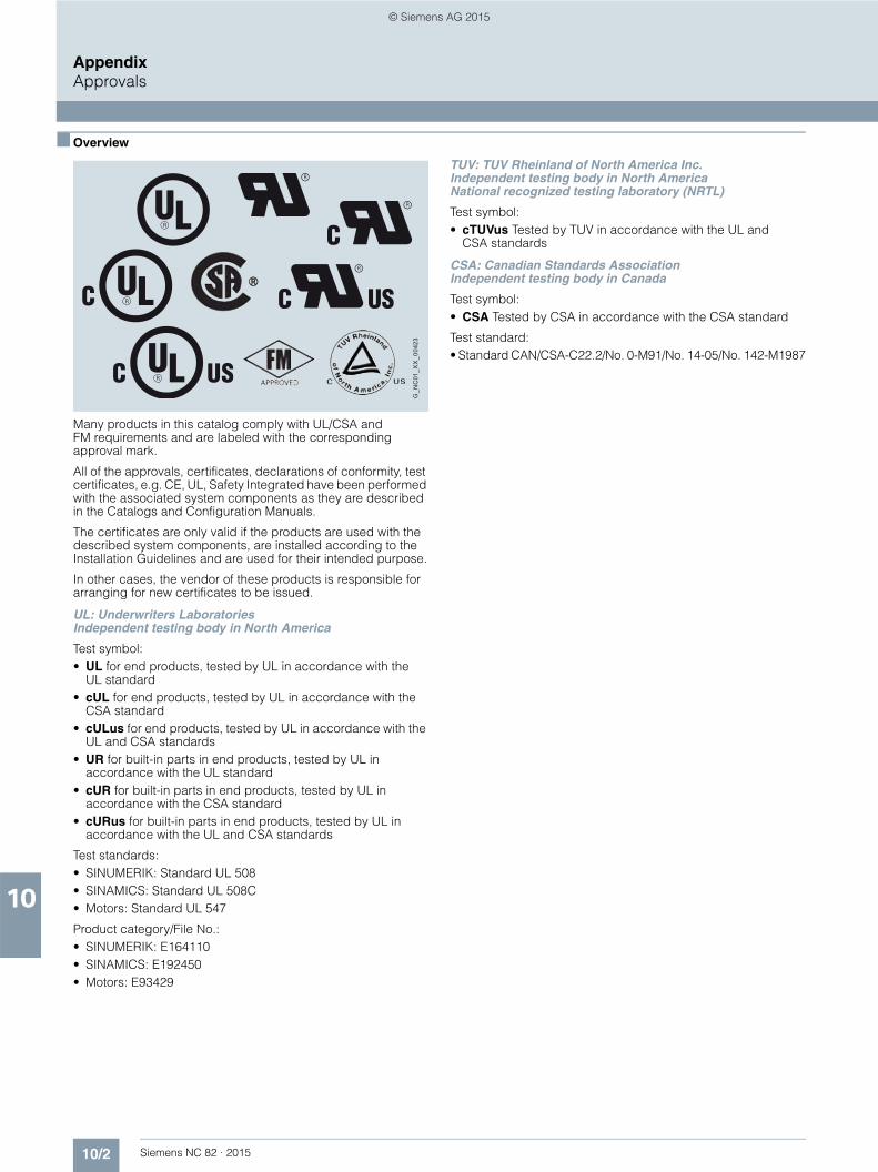
10/2 Siemens NC 82 · 2015
AppendixApprovals
10
■ Overview
Many products in this catalog comply with UL/CSA and FM requirements and are labeled with the corresponding approval mark.
All of the approvals, certificates, declarations of conformity, test certificates, e.g. CE, UL, Safety Integrated have been performed with the associated system components as they are described in the Catalogs and Configuration Manuals.
The certificates are only valid if the products are used with the described system components, are installed according to the Installation Guidelines and are used for their intended purpose.
In other cases, the vendor of these products is responsible for arranging for new certificates to be issued.
UL: Underwriters Laboratories Independent testing body in North America
Test symbol:• UL for end products, tested by UL in accordance with the
UL standard • cUL for end products, tested by UL in accordance with the
CSA standard • cULus for end products, tested by UL in accordance with the
UL and CSA standards • UR for built-in parts in end products, tested by UL in
accordance with the UL standard • cUR for built-in parts in end products, tested by UL in
accordance with the CSA standard • cURus for built-in parts in end products, tested by UL in
accordance with the UL and CSA standards
Test standards:• SINUMERIK: Standard UL 508• SINAMICS: Standard UL 508C• Motors: Standard UL 547
Product category/File No.:• SINUMERIK: E164110• SINAMICS: E192450• Motors: E93429
TUV: TUV Rheinland of North America Inc. Independent testing body in North America National recognized testing laboratory (NRTL)
Test symbol:• cTUVus Tested by TUV in accordance with the UL and
CSA standards
CSA: Canadian Standards Association Independent testing body in Canada
Test symbol:• CSA Tested by CSA in accordance with the CSA standard
Test standard:• Standard CAN/CSA-C22.2/No. 0-M91/No. 14-05/No. 142-M1987
G_N
C01
_XX
_004
23
© Siemens AG 2015

10/3Siemens NC 82 · 2015
AppendixPartner at Siemens
10
At Siemens we are resolutely pursuing the same goal: long-term improvement of your competitive ability. We are committed to this goal. Thanks to our commitment, we continue to set new standards in automation and drive technology. In all industries – worldwide.
At your service locally, around the globe for consulting, sales, training, service, support, spare parts ... on the entire Industry Automation and Drive Technologies range.
Your personal contact can be found in our Contacts Database at:www.siemens.com/automation/partner
You start by selecting • the required competence, • products and branches, • a country, • a city
or by a• location search or• person search.
© Siemens AG 2015
10/4 Siemens NC 82 · 2015
AppendixOnline services
Information and Ordering Options on the Internet and DVD
10
■ The Future of Manufacturing in the WWW
Detailed knowledge of the range of products and services available is essential when planning and engineering automa-tion systems. It goes without saying that this information must always be as up-to-date as possible.
Industry is on the threshold of the fourth industrial revolution as digitization now follows after the automation of production. The goals are to increase productivity and efficiency, speed, and quality. In this way, companies can remain competitive on the path to the future of industry.
You will find everything you need to know about products, systems and services on the internet at:
www.siemens.com/industry
■ Product Selection Using the Interactive CA 01 Automation and Drives Catalog
Detailed information together with user-friendly interactive functions: The CA 01 interactive catalog covers more than 100,000 products, thus providing a comprehensive overview of the product range provided by Siemens.
You will find everything you need here for solving tasks in the fields of automation, switching, installation and drives. All information is provided over a user interface that is both user-friendly and intuitive.
You can order the CA 01 product catalog from your Siemens sales contact or in the Information and Download Center:
www.siemens.com/industry/infocenter
Information about the CA 01 interactive catalog can be found on the Internet at:
www.siemens.com/automation/ca01
or on DVD.
■ Easy Shopping with the Industry Mall
The Industry Mall is the electronic ordering platform of Siemens AG on the Internet. Here you have online access to a huge range of products presented in an informative and attractive way.
Data transfer via EDIFACT allows the whole procedure, from selection through ordering to tracking and tracing, to be carried out online. Availability checks, customer-specific discounts and bid creation are also possible.
Numerous additional functions are provided for your support. For example, powerful search functions make it easy to select the required products. Configurators enable you to configure complex product and system components quickly and easily. CAx data types are also provided here.
You can find the Industry Mall on the Internet at:
www.siemens.com/industrymall
© Siemens AG 2015

10/5Siemens NC 82 · 2015
AppendixOnline services
Information and Download Center, Social Media, Mobile Media
10
■ Downloading Catalogs
In addition to numerous other useful documents, you can also find the catalogs listed on the back inside cover of this catalog in the Information and Download Center. You can download these catalogs in PDF format without having to register.
The filter dialog above the first catalog displayed makes it possible to carry out targeted searches. If you enter "MD 3" for example, you will find both the MD 30.1 and MD 31.1 catalogs. If you enter "IC 10", both the IC 10 catalog and the associated news or add-ons are displayed.
Visit us at:
www.siemens.com/industry/infocenter
■ Social and Mobile Media
Connect with Siemens through social media: visit our social networking sites for a wealth of useful information, demos on products and services, the opportunity to provide feedback, to exchange information and ideas with customers and other Siemens employees, and much, much more. Stay in the know and follow us on the ever-expanding global network of social media.
To find out more about Siemens' current social media activities, visit us at:
www.siemens.com/socialmedia
Or via our product pages at:
www.siemens.com/automation or www.siemens.com/drives
Connect with Siemens Industry at our central access point to read all the news on the future of manufacturing, watch current videos and inform yourself about all the latest industry developments:
www.siemens.com/future-of-manufacturing/news.html
Discover the world of Siemens.
We are also constantly expanding our offering of cross-platform apps for smartphones and tablets. You will find the current Siemens apps at the App Store (iOS) or at Google Play (Android):
https://itunes.apple.com/en/app/siemens/id452698392?mt=8
https://play.google.com/store/search?q=siemens
The Siemens app, for example, tells you all about the history, latest developments and future plans of the company – with informative pictures, fascinating reports and the most recent press releases.
© Siemens AG 2015

10/6 Siemens NC 82 · 2015
AppendixNotes on software
Software licenses
10
■ Overview
Software typesSoftware requiring a license is categorized into types.The following software types have been defined:• Engineering software• Runtime software
Engineering softwareThis includes all software products for creating (engineering) user software, e.g. for configuring, programming, parameteriz-ing, testing, commissioning or servicing. Data generated with engineering software and executable programs can be duplicated for your own use or for use by third-parties free-of-charge.
Runtime softwareThis includes all software products required for plant/machine operation, e.g. operating system, basic system, system expansions, drivers, etc.The duplication of the runtime software and executable pro-grams created with the runtime software for your own use or for use by third-parties is subject to a charge. You can find information about license fees according to use in the ordering data (e.g. in the catalog). Examples of categories of use include per CPU, per installation, per channel, per instance, per axis, per control loop, per variable, etc.Information about extended rights of use for parameteriza-tion/configuration tools supplied as integral components of the scope of delivery can be found in the readme file supplied with the relevant product(s).
License typesSiemens Industry Automation & Drive Technologies offers various types of software license:• Floating license• Single license• Rental license• Rental floating license• Trial license• Demo license• Demo floating license
Floating licenseThe software may be installed for internal use on any number of devices by the licensee. Only the concurrent user is licensed. The concurrent user is the person using the program. Use begins when the software is started. A license is required for each concurrent user.
Single licenseUnlike the floating license, a single license permits only one installation of the software per license. The type of use licensed is specified in the ordering data and in the Certificate of License (CoL). Types of use include for example per instance, per axis, per channel, etc. One single license is required for each type of use defined.
Rental licenseA rental license supports the "sporadic use" of engineering software. Once the license key has been installed, the software can be used for a specific period of time (the operating hours do not have to be consecutive). One license is required for each installation of the software.
Rental floating licenseThe rental floating license corresponds to the rental license, except that a license is not required for each installation of the software. Rather, one license is required per object (for example, user or device).
Trial licenseA trial license supports "short-term use" of the software in a non-productive context, e.g. for testing and evaluation purposes. It can be transferred to another license.
Demo licenseThe demo license support the "sporadic use" of engineering soft-ware in a non-productive context, for example, use for testing and evaluation purposes. It can be transferred to another license. After the installation of the license key, the software can be operated for a specific period of time, whereby usage can be interrupted as often as required.One license is required per installation of the software.
Demo floating licenseThe demo floating license corresponds to the demo license, except that a license is not required for each installation of the software. Rather, one license is required per object (for example, user or device).
Certificate of license (CoL)The CoL is the licensee's proof that the use of the software has been licensed by Siemens. A CoL is required for every type of use and must be kept in a safe place.
DowngradingThe licensee is permitted to use the software or an earlier version/release of the software, provided that the licensee owns such a version/release and its use is technically feasible.
Delivery versionsSoftware is constantly being updated.The following delivery versions• PowerPack• Upgradecan be used to access updates.Existing bug fixes are supplied with the ServicePack version.
PowerPackPowerPacks can be used to upgrade to more powerful software.The licensee receives a new license agreement and CoL (Certificate of License) with the PowerPack. This CoL, together with the CoL for the original product, proves that the new soft-ware is licensed. A separate PowerPack must be purchased for each original license of the software to be replaced.
UpgradeAn upgrade permits the use of a new version of the software on the condition that a license for a previous version of the product is already held.The licensee receives a new license agreement and CoL with the upgrade. This CoL, together with the CoL for the previous product, proves that the new version is licensed.A separate upgrade must be purchased for each original license of the software to be upgraded.
© Siemens AG 2015

10/7Siemens NC 82 · 2015
AppendixNotes on software
Software licenses
10
■ Overview
ServicePackServicePacks are used to debug existing products. ServicePacks may be duplicated for use as prescribed accord-ing to the number of existing original licenses.
License keySiemens Industry Automation & Drive Technologies supplies software products with and without license keys.The license key serves as an electronic license stamp and is also the "switch" for activating the software (floating license, rental license, etc.).The complete installation of software products requiring license keys includes the program to be licensed (the software) and the license key (which represents the license).
Software Update Service (SUS)As part of the SUS contract, all software updates for the respec-tive product are made available to you free of charge for a period of one year from the invoice date. The contract will automatically be extended for one year if it is not canceled three months before it expires.The possession of the current version of the respective software is a basic condition for entering into an SUS contract.
You can download explanations concerning license conditions fromwww.siemens.com/automation/salesmaterial-as/catalog/en/ terms_of_trade_en.pdf
© Siemens AG 2015

10/8 Siemens NC 82 · 2015
AppendixNotes on software
Setup texts and software update services
10
■ Overview
The "General License Conditions for Software Products for Automation and Drives" are applicable for supplies and deliveries of I DT software products.
Legal notes during setup for new software products
All software products feature a uniform reference to the license conditions. The license conditions are enclosed either with the documentation or in the software pack. When software is down-loaded from the Internet, the license contract is displayed before the ordering procedure and must be accepted by the user before downloading can continue.
Notice: This software is protected by German and/or US copyright laws and the regulations of international agreements. Unauthorized reproduction or sale of this software or parts of it is a criminal offense. This will lead to criminal and civil prosecution, and may result in significant fines and/or claims for damages. Prior to installing and using the software, please read the applicable license conditions for this software. You will find these in the documentation or packaging.
If you have received this software on a CD-ROM that is marked "Trial version", or accompanying software that is licensed for your use, the software is only permitted to be used for test and validation purposes in accordance with the accompanying con-ditions for the trial license. To this end, it is necessary for pro-grams, software libraries, etc. are installed on your computer. We therefore urgently recommend that installation is performed on a single-user computer or on a computer that is not used in the production process or for storing important data, since it cannot be completely excluded that existing files will be modified or overwritten. We accept no liability whatsoever for damage and/or data losses that result from this installation or the non-observance of this warning. Every other type of use of this soft-ware is only permitted if you are in possession of a valid license from Siemens is obtained.
If you are not in possession of a valid license that can be proven by presenting an appropriate Certificate of License/software product certificate, please abort installation immediately and contact a Siemens office without delay to avoid claims for damages.
■ Overview (continued)
Software update services
Order To order the software update service, an article number must be specified. The software update service can be ordered when the software products are ordered or at a later date. Subsequent orders require that the ordering party is in possession at least of a single license.
Note: It is recommended that the software update service is ordered as early as possible. If a new software version of a software product is released for delivery by Siemens, only those custom-ers will receive it automatically who are entered in the appropri-ate delivery list at Siemens at this time. Previous software ver-sions, or the current software version are not supplied when the software update service is ordered. The software update service requires that the software product is up-to-date at the time of completion of the contract for the software update service.
Delivery When a software update service is ordered, you will be sent the contractual conditions of this service and the price is due for payment. At the same time, you will be included in a delivery list for the software product to be updated. If Siemens releases a new software version for the corresponding software product for general sale (function version or product version), it will be delivered automatically to the goods recipient specified in the delivery address within the contract period.
■ More information
Security information
Siemens provides products and solutions with industrial security functions that support the secure operation of plants, solutions, machines, equipment and/or networks. They are important com-ponents in a holistic industrial security concept. With this in mind, Siemens’ products and solutions undergo continuous development. Siemens recommends strongly that you regularly check for product updates.
For the secure operation of Siemens products and solutions, it is necessary to take suitable preventive action (e.g. cell protection concept) and integrate each component into a holistic, state-of-the-art industrial security concept. Third-party products that may be in use should also be considered. For more information about industrial security, visit
www.siemens.com/industrialsecurity
To stay informed about product updates as they occur, sign up for a productspecific newsletter. For more information, visit
http://support.automation.siemens.com
© Siemens AG 2015
10/9Siemens NC 82 · 2015
AppendixIndexes
Subject index
10
Numerical Page> 5 screens, extended functions ......................................................2/10, 2/2824 V terminal adapter ............................................4/16, 4/24, 4/32, 4/40, 4/432D representation .............................................................................2/15, 2/212D/3D protection areas..............................................................................2/212nd commissioning........................................................................3/3, 3/6, 8/22SP1 motor spindle......................................................................................2/53D representation ....................................................................2/15, 2/17, 2/2990° angle socket ........................................................................................3/15
AAB 9000 ring balancing system...................................................................9/4Absolute encoder .................2/5, 4/54, 4/56, 4/57, 5/4, 6/2, 6/4, 7/8, 7/9, 7/16Access MyMachine /Ethernet ....................................................................2/26Access MyMachine /OPC UA...........................................................2/19, 2/30Access MyMachine /P2P .........................................2/24, 2/25, 2/30, 3/5, 3/11Access protection for cycles ............................................................2/14, 2/28Accessories pack ........................................................................................4/2Active Interface Module.............................................................................4/26Active Line Module ....................................................................................4/24Adapter set ................................................................................................3/17Advanced Surface .......................................................................2/7, 2/9, 2/30Advanced technology functions .......................................................2/14, 2/29Answers for industry .......................................................................................3Antenna.............................................................................................2/25, 3/21Approvals...................................................................................................10/2Asynchronous motors ..................................................................................5/6Automatic...................................................................................................2/16Axis functions...............................................................................................2/6Axis/spindle, each additional..............................................................2/3, 2/27
BBackup workpiece setup data..........................................................2/13, 2/30Balance Cutting ................................................................................2/14, 2/28Basic Line Filter .........................................................................................4/27Basic Line Module .....................................................................................4/32Braking Module..........................................................................................4/45Braking resistor ..........................................................................................4/46
CCable set...........................................................................................3/14, 3/19CAD CREATOR..............................................................................3/1, 4/1, 5/1Capacitor Module ......................................................................................4/47Card reader USB 2.0 .................................................................................2/20Circuit breaker .........................................................................4/19, 4/28, 4/35Clamp ..........................................................................................................6/6CNC controls ...............................................................................................1/2CNC high-level language ..........................................................................2/11CNC lock function...............................................................................2/3, 2/28CNC programming language ...........................................................2/11, 2/12CNC user memory expansion.............................................................2/3, 2/30Commissioning ...................................................................................2/24, 8/2Commissioning Manual ...............................................................................8/3CompactFlash card ...................................................................2/20, 3/5, 3/11Compensations..........................................................................................2/22Conditions of sale and delivery ...............................................................10/20Connection kit for mini handheld unit ...............................................2/20, 3/15Connection overviews...................................................................7/3, 7/4 – 7/9Connector ..................................................................................................4/57Contact block with 2 contacts ..........................................................3/12, 3/13Contact ......................................................................................................10/3Contour handwheel.............................................................................2/9, 2/30Control structure and configuration .............................................................2/2Control Supply Module ..............................................................................4/48Conversion tables ....................................................................................10/15Couplings.....................................................................................................2/7Ctrl-Energy..........................................................................................1/9, 2/25Current-carrying capacity of cables with copper cores ..............................7/3Cylinder fault compensation ......................................................................2/22
DData management .....................................................................................2/19DC link adapter.............................................4/16, 4/24, 4/32, 4/40, 4/43, 4/49DC link busbar set ............................................................................4/40, 4/43DC link rectifier adapter ................................4/16, 4/24, 4/32, 4/40, 4/43, 4/49Definition of lengths for pre-assembled cables.........................................7/17Derating factors ...........................................................................................7/3Diagnostic functions .........................................................................2/25, 2/26Diagnostics Manual .....................................................................................8/4DIAZED fuse ..............................................................................................4/28Dimensional drawings .....................................................................5/14 – 5/20Display active synchronized actions in HMI..............................................2/10DMC20 DRIVE-CLiQ Hub Module ...............................................2/4, 4/50, 7/7
D (continued) PageDME20 DRIVE-CLiQ Hub Module ......................................................2/4, 4/51Documentation ............................................................................................8/3Double Motor Modules in booksize compact format ................................4/13Double Motor Modules in booksize format......................................4/41 – 4/43DQI encoder................................................................................................2/5DRF offset ..................................................................................................2/16Drive Based Safety Integrated .........................................................2/31, 4/58Drive system.........................................................................................1/5, 4/2Drive-autonomous extended stop and retract ESR..........................2/21, 2/28DRIVE-CLiQ cable, pre-assembled...........................................................4/26DRIVE-CLiQ signal cable, pre-assembled ..............................3/11, 3/19, 7/13Drives .................................................................2/2, 2/4, 2/7, 2/10, 2/28, 8/13Dust-proof blanking plugs ..................4/16, 4/24, 4/32, 4/40, 4/43, 4/50 – 4/52DXF Reader for PC ...........................................................................2/14, 2/30
EElectronic handwheel .........................................................2/20, 3/17, 7/4, 7/5Emergency stop mushroom pushbutton ..........................................3/12, 3/13EMUGE Factory for precision tools
Richard Glimpel GmbH & Co. KG...........................................................9/3Energy efficiency .........................................................................................1/9Engineering ...............................................................................................2/10Engineering tool SIZER for Siemens Drives ..............................3/5, 3/11, 8/13Evaluation of internal drive variables, basic.....................................2/10, 2/28Execution from external storage EES .................................................2/3, 2/30Execution from network drive .................................................................... 2/16Export regulations ...................................................................................10/20Extended block search.....................................................................2/16, 2/30Extended operator functions ...................................................2/21, 2/29, 2/30Extended Safety Integrated functions .......................................1/8, 2/31, 4/59External fan module.....................................................................................4/8
FFeed override ...................................................................................3/12, 3/13Feed/rapid traverse override electronic rotary switch...............................3/14Flange socket for portable handwheel.............................................2/20, 3/17FRANKEN GmbH & Co. KG ........................................................................9/3Friction compensation ......................................................................2/22, 2/28Front cover.......................................................................................... 3/5, 3/11Function Manual ..........................................................................................8/6Fuse switch disconnector........................................................4/19, 4/28, 4/35
GGeneric coupling basic, CP-Basic .....................................................2/7, 2/27Generic coupling comfort, CP-Comfort..............................................2/8, 2/28Generic coupling static, CP-Static .....................................................2/7, 2/27G-Tech .........................................................................................................1/4
HHandwheel, electronic........................................................2/20, 3/17, 7/4, 7/5High speed settings ....................................................................................2/9Hofmann Mess- und Auswuchttechnik GmbH & Co. KG............................9/4Holder ...............................................................................................3/15, 3/17Host computer connection ...............................................................2/19, 2/30
II/O module.......................................................... 2/23, 2/31, 3/19, 7/4, 7/5, 7/8Inclined axis .......................................................................................2/8, 2/27Incremental encoder ..................................2/5, 4/54, 4/55, 6/2, 7/7 – 7/9, 7/16Industry Mall ..............................................................................................10/4Information and Ordering Options ............................................................10/4Integrated spindle monitor ISM ........................................................2/25, 2/28Interpolations...............................................................................................2/7
JJOG ...........................................................................................................2/15
LLanguage extensions ................................................................2/21, 3/5, 3/11Leading auxiliary switch ............................................................................ 4/28Leadscrew error compensation........................................................2/22, 2/28Length code ..............................................................................................7/17Line filters ................................................................................4/10, 4/18, 4/34Line reactors..............................................................................4/9, 4/17, 4/33Linear measuring systems ..........................................................................2/5Load/save MDI program............................................................................ 2/15
MMachine adaptation for SinuTrain................................................................8/9Machine control panel .............................................................2/20, 3/12, 3/13Machining step programming ShopTurn/ShopMill ....................1/3, 2/13, 2/29Main switch..............................................................................4/19, 4/28, 4/35Manage additional drives.................................................................2/19, 2/29Manual..................................................................................................8/3, 8/4MARPOSS S.p.A..........................................................................................9/5
© Siemens AG 2015
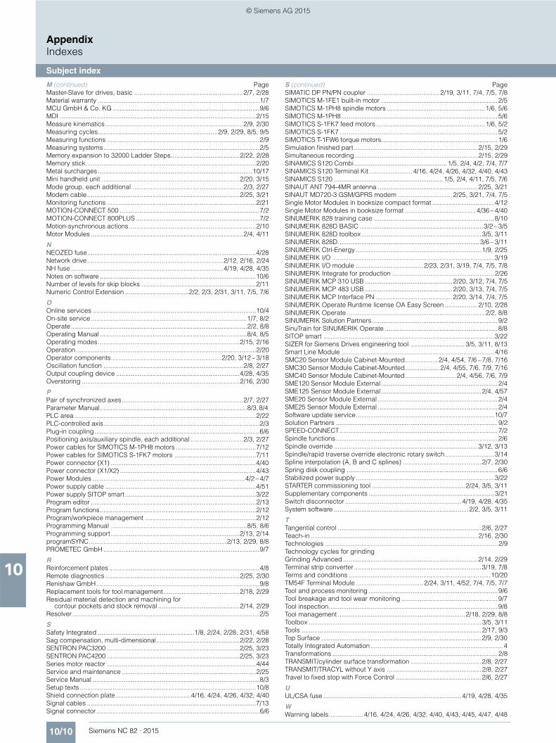
10/10 Siemens NC 82 · 2015
AppendixIndexes
Subject index
10
M (continued) PageMaster-Slave for drives, basic ............................................................2/7, 2/28Material warranty .........................................................................................1/7MCU GmbH & Co. KG .................................................................................9/6MDI ............................................................................................................2/15Measure kinematics............................................................................2/9, 2/30Measuring cycles..................................................................2/9, 2/29, 8/5, 9/5Measuring functions ....................................................................................2/9Measuring systems......................................................................................2/5Memory expansion to 32000 Ladder Steps......................................2/22, 2/28Memory stick..............................................................................................2/20Metal surcharges .....................................................................................10/17Mini handheld unit ............................................................................2/20, 3/15Mode group, each additional .............................................................2/3, 2/27Modem cable....................................................................................2/25, 3/21Monitoring functions ..................................................................................2/21MOTION-CONNECT 500 .............................................................................7/2MOTION-CONNECT 800PLUS ....................................................................7/2Motion-synchronous actions......................................................................2/10Motor Modules ....................................................................................2/4, 4/11
NNEOZED fuse.............................................................................................4/28Network drive...........................................................................2/12, 2/16, 2/24NH fuse ....................................................................................4/19, 4/28, 4/35Notes on software ......................................................................................10/6Number of levels for skip blocks ...............................................................2/11Numeric Control Extension ...................................2/2, 2/3, 2/31, 3/11, 7/5, 7/6
OOnline services ..........................................................................................10/4On-site service......................................................................................1/7, 8/2Operate.................................................................................................2/2, 8/8Operating Manual .................................................................................8/4, 8/5Operating modes..............................................................................2/15, 2/16Operation ...................................................................................................2/20Operator components.............................................................2/20, 3/12 – 3/18Oscillation function .............................................................................2/8, 2/27Output coupling device ....................................................................4/28, 4/35Overstoring .......................................................................................2/16, 2/30
PPair of synchronized axes...................................................................2/7, 2/27Parameter Manual.................................................................................8/3, 8/4 PLC area ....................................................................................................2/22PLC-controlled axis......................................................................................2/3Plug-in coupling...........................................................................................6/6Positioning axis/auxiliary spindle, each additional .............................2/3, 2/27Power cables for SIMOTICS M-1PH8 motors ............................................7/12Power cables for SIMOTICS S-1FK7 motors .............................................7/11Power connector (X1) ................................................................................4/40Power connector (X1/X2) ...........................................................................4/43Power Modules ....................................................................................4/2 – 4/7Power supply cable ...................................................................................4/51Power supply SITOP smart ........................................................................3/22Program editor ...........................................................................................2/13Program functions......................................................................................2/12Program/workpiece management .............................................................2/12Programming Manual ...........................................................................8/5, 8/6Programming support.......................................................................2/13, 2/14programSYNC............................................................................2/13, 2/29, 8/8PROMETEC GmbH ......................................................................................9/7
RReinforcement plates...................................................................................4/8Remote diagnostics ..........................................................................2/25, 2/30Renishaw GmbH..........................................................................................9/8Replacement tools for tool management..........................................2/18, 2/29Residual material detection and machining for
contour pockets and stock removal .............................................2/14, 2/29Resolver .......................................................................................................2/5
SSafety Integrated .....................................................1/8, 2/24, 2/28, 2/31, 4/58Sag compensation, multi-dimensional..............................................2/22, 2/28SENTRON PAC3200 .........................................................................2/25, 3/23SENTRON PAC4200 .........................................................................2/25, 3/23Series motor reactor ..................................................................................4/44Service and maintenance ..........................................................................2/25Service Manual ............................................................................................8/3Setup texts .................................................................................................10/8Shield connection plate .........................................4/16, 4/24, 4/26, 4/32, 4/40Signal cables .............................................................................................7/13Signal connector..........................................................................................6/6
S (continued) PageSIMATIC DP PN/PN coupler ........................................2/19, 3/11, 7/4, 7/5, 7/8SIMOTICS M-1FE1 built-in motor ................................................................2/5SIMOTICS M-1PH8 spindle motors ......................................................1/6, 5/6SIMOTICS M-1PH8......................................................................................5/6SIMOTICS S-1FK7 feed motors ............................................................1/6, 5/2SIMOTICS S-1FK7 .......................................................................................5/2SIMOTICS T-1FW6 torque motors................................................................1/6Simulation finished part ....................................................................2/15, 2/29Simultaneous recording....................................................................2/15, 2/29SINAMICS S120 Combi...................................................1/5, 2/4, 4/2, 7/4, 7/7SINAMICS S120 Terminal Kit........................4/16, 4/24, 4/26, 4/32, 4/40, 4/43SINAMICS S120 ............................................................1/5, 2/4, 4/11, 7/5, 7/6SINAUT ANT 794-4MR antenna .......................................................2/25, 3/21SINAUT MD720-3 GSM/GPRS modem ..............................2/25, 3/21, 7/4, 7/5Single Motor Modules in booksize compact format .................................. 4/12Single Motor Modules in booksize format .......................................4/36 – 4/40SINUMERIK 828 training case ..................................................................8/10SINUMERIK 828D BASIC ....................................................................3/2 – 3/5SINUMERIK 828D toolbox..................................................................3/5, 3/11SINUMERIK 828D..............................................................................3/6 – 3/11SINUMERIK Ctrl-Energy ..................................................................... 1/9, 2/25SINUMERIK I/O ......................................................................................... 3/19SINUMERIK I/O module ..................................... 2/23, 2/31, 3/19, 7/4, 7/5, 7/8SINUMERIK Integrate for production ........................................................2/26SINUMERIK MCP 310 USB ................................................2/20, 3/12, 7/4, 7/5SINUMERIK MCP 483 USB ................................................2/20, 3/13, 7/4, 7/5SINUMERIK MCP Interface PN ..........................................2/20, 3/14, 7/4, 7/5SINUMERIK Operate Runtime license OA Easy Screen ..................2/10, 2/28SINUMERIK Operate ............................................................................2/2, 8/8SINUMERIK Solution Partners .....................................................................9/2SinuTrain for SINUMERIK Operate ..............................................................8/8SITOP smart ..............................................................................................3/22SIZER for Siemens Drives engineering tool ..............................3/5, 3/11, 8/13Smart Line Module ....................................................................................4/16SMC20 Sensor Module Cabinet-Mounted..................2/4, 4/54, 7/6 – 7/8, 7/16SMC30 Sensor Module Cabinet-Mounted...................2/4, 4/55, 7/6, 7/9, 7/16SMC40 Sensor Module Cabinet-Mounted............................2/4, 4/56, 7/6, 7/9SME120 Sensor Module External ................................................................2/4SME125 Sensor Module External .......................................................2/4, 4/57SME20 Sensor Module External ..................................................................2/4SME25 Sensor Module External ..................................................................2/4Software update service............................................................................ 10/7Solution Partners .........................................................................................9/2SPEED-CONNECT.......................................................................................7/2Spindle functions.........................................................................................2/6Spindle override ...............................................................................3/12, 3/13Spindle/rapid traverse override electronic rotary switch...........................3/14Spline interpolation (A, B and C splines) ...........................................2/7, 2/30Spring disk coupling ...................................................................................6/6Stabilized power supply ............................................................................ 3/22STARTER commissioning tool ...................................................2/24, 3/5, 3/11Supplementary components .....................................................................3/21Switch disconnector ................................................................4/19, 4/28, 4/35System software ..........................................................................2/2, 3/5, 3/11
TTangential control ...............................................................................2/6, 2/27Teach-in ............................................................................................2/16, 2/30Technologies ...............................................................................................2/9Technology cycles for grindingGrinding Advanced ..........................................................................2/14, 2/29Terminal strip converter ......................................................................3/19, 7/8Terms and conditions ..............................................................................10/20TM54F Terminal Module ..................................... 2/24, 3/11, 4/52, 7/4, 7/5, 7/7Tool and process monitoring .......................................................................9/6Tool breakage and tool wear monitoring .....................................................9/7Tool inspection.............................................................................................9/8Tool management ......................................................................2/18, 2/29, 8/8Toolbox ...............................................................................................3/5, 3/11Tools ...................................................................................................2/17, 9/3Top Surface ........................................................................................2/9, 2/30Totally Integrated Automation......................................................................... 4Transformations ...........................................................................................2/8TRANSMIT/cylinder surface transformation .......................................2/8, 2/27TRANSMIT/TRACYL without Y axis ....................................................2/8, 2/27Travel to fixed stop with Force Control ...............................................2/6, 2/27
UUL/CSA fuse ............................................................................4/19, 4/28, 4/35
WWarning labels...................4/16, 4/24, 4/26, 4/32, 4/40, 4/43, 4/45, 4/47, 4/48
© Siemens AG 2015
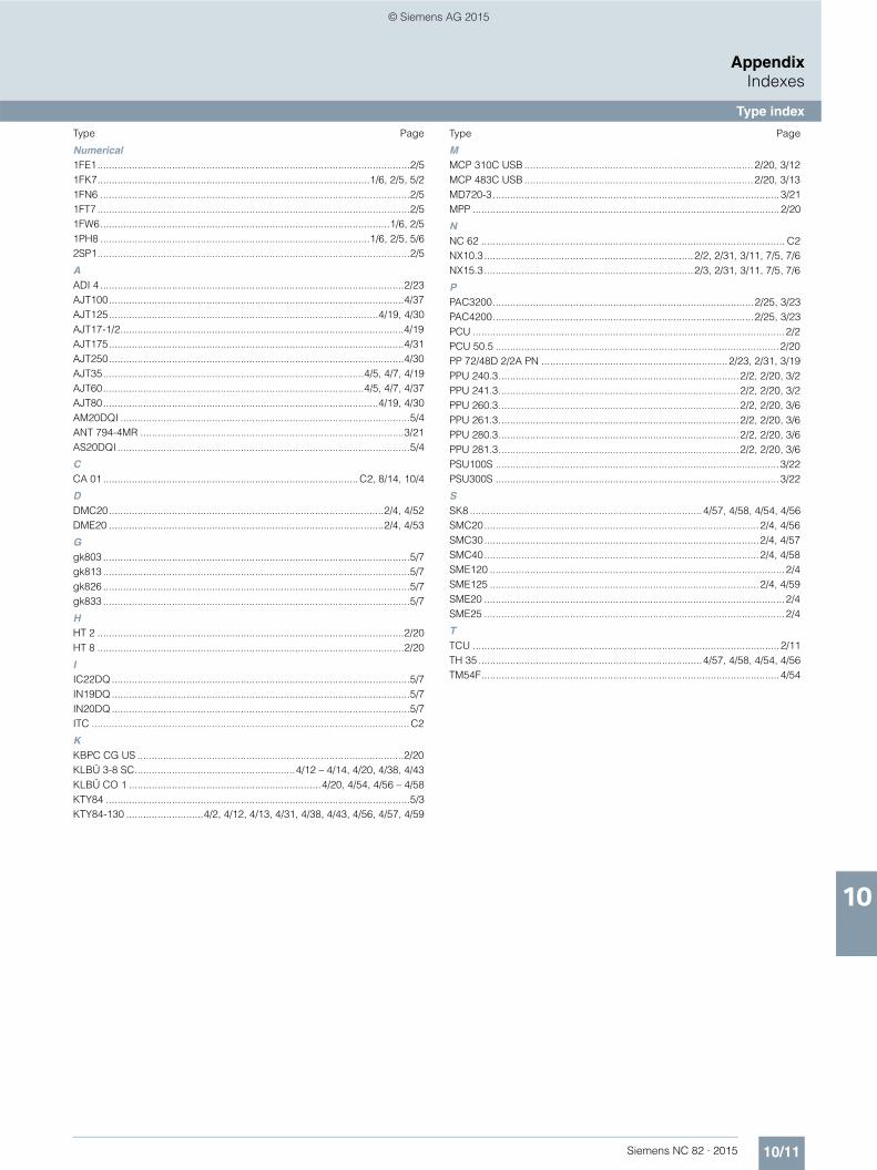
10/11Siemens NC 82 · 2015
AppendixIndexes
Type index
10
Type Page
Numerical1FE1.............................................................................................................2/51FK7...............................................................................................1/6, 2/5, 5/21FN6 ............................................................................................................2/51FT7 .............................................................................................................2/51FW6.....................................................................................................1/6, 2/51PH8 ..............................................................................................1/6, 2/5, 5/62SP1.............................................................................................................2/5
AADI 4 ..........................................................................................................2/23AJT100.......................................................................................................4/37AJT125..............................................................................................4/19, 4/30AJT17-1/2...................................................................................................4/19AJT175.......................................................................................................4/31AJT250.......................................................................................................4/30AJT35...........................................................................................4/5, 4/7, 4/19AJT60...........................................................................................4/5, 4/7, 4/37AJT80................................................................................................4/19, 4/30AM20DQI .....................................................................................................5/4ANT 794-4MR ............................................................................................3/21AS20DQI ......................................................................................................5/4
CCA 01 .........................................................................................C2, 8/14, 10/4
DDMC20................................................................................................2/4, 4/52DME20 ................................................................................................2/4, 4/53
Ggk803 ...........................................................................................................5/7gk813 ...........................................................................................................5/7gk826 ...........................................................................................................5/7gk833 ...........................................................................................................5/7
HHT 2 ...........................................................................................................2/20HT 8 ...........................................................................................................2/20
IIC22DQ ........................................................................................................5/7IN19DQ ........................................................................................................5/7IN20DQ ........................................................................................................5/7ITC ...............................................................................................................C2
KKBPC CG US .............................................................................................2/20KLBÜ 3-8 SC........................................................4/12 – 4/14, 4/20, 4/38, 4/43KLBÜ CO 1 ...................................................................4/20, 4/54, 4/56 – 4/58KTY84 ..........................................................................................................5/3KTY84-130 ...........................4/2, 4/12, 4/13, 4/31, 4/38, 4/43, 4/56, 4/57, 4/59
Type Page
MMCP 310C USB ................................................................................2/20, 3/12MCP 483C USB ................................................................................2/20, 3/13MD720-3....................................................................................................3/21MPP ...........................................................................................................2/20
NNC 62 .......................................................................................................... C2NX10.3.........................................................................2/2, 2/31, 3/11, 7/5, 7/6NX15.3.........................................................................2/3, 2/31, 3/11, 7/5, 7/6
PPAC3200...........................................................................................2/25, 3/23PAC4200...........................................................................................2/25, 3/23PCU .............................................................................................................2/2PCU 50.5 ...................................................................................................2/20PP 72/48D 2/2A PN .................................................................2/23, 2/31, 3/19PPU 240.3....................................................................................2/2, 2/20, 3/2PPU 241.3....................................................................................2/2, 2/20, 3/2PPU 260.3....................................................................................2/2, 2/20, 3/6PPU 261.3....................................................................................2/2, 2/20, 3/6PPU 280.3....................................................................................2/2, 2/20, 3/6PPU 281.3....................................................................................2/2, 2/20, 3/6PSU100S ...................................................................................................3/22PSU300S ...................................................................................................3/22
SSK8 .................................................................................4/57, 4/58, 4/54, 4/56SMC20................................................................................................2/4, 4/56SMC30................................................................................................2/4, 4/57SMC40................................................................................................2/4, 4/58SME120 .......................................................................................................2/4SME125 ..............................................................................................2/4, 4/59SME20 .........................................................................................................2/4SME25 .........................................................................................................2/4
TTCU ...........................................................................................................2/11TH 35 ..............................................................................4/57, 4/58, 4/54, 4/56TM54F........................................................................................................4/54
© Siemens AG 2015
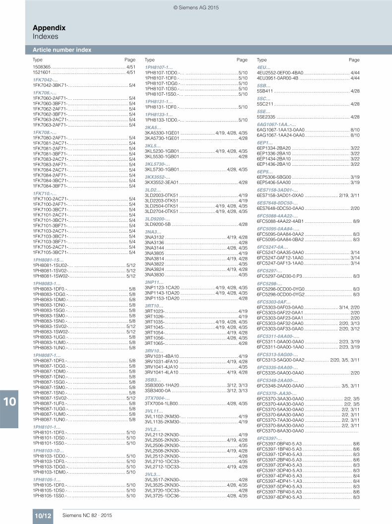
10/12 Siemens NC 82 · 2015
AppendixIndexes
Article number index
10
Type Page
1508365 .......................................................... 4/511521601 .......................................................... 4/51
1FK7042-…1FK7042-3BK71-…........................................... 5/4
1FK706.-…1FK7060-2AF71-… ........................................... 5/41FK7060-3BF71-............................................... 5/41FK7062-2AF71-… ........................................... 5/41FK7062-3BF71-............................................... 5/41FK7063-2AC71-…........................................... 5/41FK7063-2AF71-............................................... 5/4
1FK708.-…1FK7080-2AF71-… ........................................... 5/41FK7081-2AC71-…........................................... 5/41FK7081-2AF71-… ........................................... 5/41FK7081-3BF71-… ........................................... 5/41FK7083-2AC71-…........................................... 5/41FK7083-2AF71-… ........................................... 5/41FK7084-2AC71-…........................................... 5/41FK7084-2AF71-… ........................................... 5/41FK7084-3BC71-…........................................... 5/41FK7084-3BF71-… ........................................... 5/4
1FK710.-…1FK7100-2AC71-…........................................... 5/41FK7100-2AF71-… ........................................... 5/41FK7100-3BC71-…........................................... 5/41FK7101-2AC71-…........................................... 5/41FK7101-3BC71-…........................................... 5/41FK7101-3BF71-… ........................................... 5/41FK7103-2AC71-…........................................... 5/41FK7103-3BC71-…........................................... 5/41FK7103-3BF71-… ........................................... 5/41FK7105-2AC71-…........................................... 5/41FK7105-3BC71-…........................................... 5/4
1PH8081-1S…1PH8081-1SU02-… ........................................ 5/121PH8081-1SV02-…......................................... 5/121PH8081-1SW02-…........................................ 5/12
1PH8083-1…1PH8083-1DF0.-…............................................ 5/81PH8083-1DG0.-…........................................... 5/81PH8083-1DM0.-…........................................... 5/81PH8083-1DN0.-… ........................................... 5/81PH8083-1SG0.-… ........................................... 5/81PH8083-1SM0.-… ........................................... 5/81PH8083-1SN0.-… ........................................... 5/81PH8083-1SV02-…......................................... 5/121PH8083-1SW02-…........................................ 5/121PH8083-1UG0.-…........................................... 5/81PH8083-1UM0.-…........................................... 5/81PH8083-1UN0.-… ........................................... 5/8
1PH8087-1…1PH8087-1DF0.-…............................................ 5/81PH8087-1DG0.-…........................................... 5/81PH8087-1DM0.-…........................................... 5/81PH8087-1DN0.-… ........................................... 5/81PH8087-1SG0.-… ........................................... 5/81PH8087-1SM0.-… ........................................... 5/81PH8087-1SN0.-… ........................................... 5/81PH8087-1SV02-…......................................... 5/121PH8087-1UF0.-…............................................ 5/81PH8087-1UG0.-…........................................... 5/81PH8087-1UM0.-…........................................... 5/81PH8087-1UN0.-… ........................................... 5/8
1PH8101-1…1PH8101-1DF0.-….......................................... 5/101PH8101-1DS0.-… ......................................... 5/101PH8101-1SS0.-….......................................... 5/10
1PH8103-1D…1PH8103-1DD0.-… ......................................... 5/101PH8103-1DF0.-….......................................... 5/101PH8103-1DG0.-…......................................... 5/101PH8103-1DM0.-…......................................... 5/10
1PH8105-1…1PH8105-1DF0.-….......................................... 5/101PH8105-1DS0.-… ......................................... 5/101PH8105-1SS0.-….......................................... 5/10
Type Page
1PH8107-1…1PH8107-1DD0.-… .........................................5/101PH8107-1DF0.-… ..........................................5/101PH8107-1DG0.-… .........................................5/101PH8107-1DS0.-…..........................................5/101PH8107-1SS0.-… ..........................................5/10
1PH8131-1…1PH8131-1DF0.-… ..........................................5/10
1PH8133-1…1PH8133-1DD0.-… .........................................5/10
3KA5…3KA5330-1GE01 ...........................4/19, 4/28, 4/353KA5730-1GE01 .............................................4/28
3KL5…3KL5230-1GB01............................4/19, 4/28, 4/353KL5530-1GB01..............................................4/28
3KL5730-…3KL5730-1GB01.....................................4/28, 4/35
3KX3552-…3KX3552-3EA01 ..............................................4/28
3LD2…3LD2003-0TK51 ..............................................4/193LD2203-0TK51 ..............................................4/193LD2504-0TK51 ............................4/19, 4/28, 4/353LD2704-0TK51 ............................4/19, 4/28, 4/35
3LD9200-…3LD9200-5B ....................................................4/28
3NA3…3NA3132 ................................................4/19, 4/283NA3136 .........................................................4/283NA3144 ................................................4/28, 4/353NA3805 .........................................................4/193NA3814 ................................................4/19, 4/283NA3822 .........................................................4/353NA3824 ................................................4/19, 4/283NA3830 .........................................................4/35
3NP11…3NP1123-1CA20 ...........................4/19, 4/28, 4/353NP1143-1DA20 ...........................4/19, 4/28, 4/353NP1153-1DA20 .............................................4/28
3RT10…3RT1023-... ......................................................4/193RT1026-... ......................................................4/193RT1035-... ....................................4/19, 4/28, 4/353RT1045-... ....................................4/19, 4/28, 4/353RT1054-... .............................................4/19, 4/283RT1056-... .............................................4/28, 4/353RT1065-... ......................................................4/28
3RV10…3RV1031-4BA10..............................................4/193RV1031-4FA10 .....................................4/19, 4/283RV1041-4JA10 ..............................................4/353RV1041-4LA10 .....................................4/19, 4/28
3SB3…3SB3000-1HA20.....................................3/12, 3/133SB3400-0A ...........................................3/12, 3/13
3TX7004-…3TX7004-1LB00......................................4/28, 4/35
3VL11…3VL1102-2KM30-.... ........................................4/193VL1135-2KM30-.... ........................................4/19
3VL2…3VL2112-2KN30-.... .........................................4/193VL2505-2KN30-.... ................................4/19, 4/283VL2506-2KN30-.... .........................................4/353VL2508-2KN30-.... ................................4/19, 4/283VL2512-2KN30-.... .........................................4/283VL2710-1DC33-.............................................4/353VL2712-1DC33-....................................4/19, 4/28
3VL3…3VL3517-2KN30-.... .........................................4/283VL3525-2KN30-.... ................................4/28, 4/353VL3720-1DC33-.............................................4/283VL3725-1DC36-....................................4/28, 4/35
Type Page
4EU…4EU2552-0EF00-4BA0.................................... 4/444EU3951-0AR00-4B ....................................... 4/44
5SB…5SB411 ........................................................... 4/28
5SC…5SC211 ........................................................... 4/28
5SE…5SE2335 ......................................................... 4/28
6AG1067-1AA..-…6AG1067-1AA13-0AA0................................... 8/106AG1067-1AA24-0AA0................................... 8/10
6EP1…6EP1334-2BA20 ............................................. 3/226EP1336-2BA10 ............................................. 3/226EP1434-2BA10 ............................................. 3/226EP1436-2BA10 ............................................. 3/22
6EP5…6EP5306-5BG00 ............................................. 3/196EP5406-5AA00 ............................................. 3/19
6ES7158-3AD01-…6ES7158-3AD01-0XA0 .......................... 2/19, 3/11
6ES7648-0DC50-…6ES7648-0DC50-0AA0 ................................... 2/20
6FC5088-4AA22-…6FC5088-4AA22-4AB1 ..................................... 8/9
6FC5095-0AA84-….6FC5095-0AA84-0AA2 ..................................... 8/36FC5095-0AA84-0BA2 ..................................... 8/3
6FC5247-0A…6FC5247-0AA35-0AA0 ................................... 3/146FC5247-0AF12-1AA0.................................... 3/146FC5247-0AF13-1AA0.................................... 3/14
6FC5297-…6FC5297-0AD30-0.P3....................................... 8/3
6FC5298-…6FC5298-0CD00-0YG0..................................... 8/36FC5298-0CD00-0YG2..................................... 8/3
6FC5303-0AF…6FC5303-0AF03-0AA0........................... 3/14, 2/206FC5303-0AF22-0AA1.................................... 2/206FC5303-0AF23-0AA1.................................... 2/206FC5303-0AF32-0AA0........................... 2/20, 3/136FC5303-0AF33-0AA0........................... 2/20, 3/12
6FC5311-0AA00-….6FC5311-0AA00-0AA0 .......................... 2/23, 3/196FC5311-0AA00-1AA0 .......................... 2/23, 3/19
6FC5313-5AG00-…6FC5313-5AG00-0AA2................... 2/20, 3/5, 3/11
6FC5335-0AA00-…6FC5335-0AA00-0AA0 ................................... 2/20
6FC5348-2AA00-…6FC5348-2AA00-0AA0 ............................ 3/5, 3/11
6FC5370-.AA30-…6FC5370-3AA30-0AA0 .............................. 2/2, 3/56FC5370-4AA30-0AA0 .............................. 2/2, 3/56FC5370-5AA30-0AA0 ............................ 2/2, 3/116FC5370-6AA30-0AA0 ............................ 2/2, 3/116FC5370-7AA30-0AA0 ............................ 2/2, 3/116FC5370-8AA30-0AA0 ............................ 2/2, 3/116FC5370-8AA30-0AA0 ..........................................
6FC5397-…6FC5397-0BP40-5.A3....................................... 8/66FC5397-1BP40-5.A3....................................... 8/66FC5397-1DP40-5.A3....................................... 8/36FC5397-2BP40-5.A3....................................... 8/66FC5397-2DP40-5.A3....................................... 8/36FC5397-3DP40-5.A3....................................... 8/36FC5397-4DP40-5.A3....................................... 8/46FC5397-4DP41-1.A3....................................... 8/46FC5397-5DP40-5.A3....................................... 8/36FC5397-7BP40-5.A3....................................... 8/66FC5397-8DP40-5.A3....................................... 8/3
© Siemens AG 2015
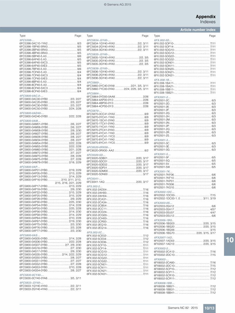
10/13Siemens NC 82 · 2015
AppendixIndexes
Article number index
10
Type Page
6FC5398-…6FC5398-0AC10-1YA2...................................... 8/36FC5398-1BP40-5RA3...................................... 8/56FC5398-2BP40-5RA3...................................... 8/56FC5398-4BP40-5RA3...................................... 8/56FC5398-5BP40-5.A3 ....................................... 8/66FC5398-6AP40-5.A3 ....................................... 8/56FC5398-6AP40-5XC3...................................... 8/56FC5398-6AP40-5XE3 ...................................... 8/56FC5398-7BP40-5.A3 ....................................... 8/66FC5398-7CP40-5.A3....................................... 8/46FC5398-7CP40-5XC3 ..................................... 8/46FC5398-7CP40-5XE3...................................... 8/46FC5398-8BP40-5.A3 ....................................... 8/46FC5398-8CP40-5.A3....................................... 8/46FC5398-8CP40-5XC3 ..................................... 8/46FC5398-8CP40-5XE3...................................... 8/4
6FC5800-0AC.0-…6FC5800-0AC00-0YB0 ............................ 2/3, 2/276FC5800-0AC20-0YB0 ............................ 2/3, 2/276FC5800-0AC30-0YB0 ............................ 2/3, 2/276FC5800-0AC50-0YB0 .......................... 2/24, 2/28
6FC5800-0AD40-…6FC5800-0AD40-0YB0 .......................... 2/22, 2/28
6FC5800-0AM…6FC5800-0AM01-0YB0 ............................ 2/6, 2/276FC5800-0AM06-0YB0 ............................ 2/6, 2/276FC5800-0AM08-0YB0 ............................ 2/9, 2/306FC5800-0AM27-0YB0 ............................ 2/8, 2/276FC5800-0AM28-0YB0 ............................ 2/8, 2/276FC5800-0AM34-0YB0 ............................ 2/8, 2/276FC5800-0AM54-0YB0 .......................... 2/22, 2/286FC5800-0AM55-0YB0 .......................... 2/22, 2/286FC5800-0AM60-0YB0 .......................... 2/21, 2/286FC5800-0AM72-0YB0 ............................ 2/7, 2/276FC5800-0AM73-0YB0 ............................ 2/8, 2/286FC5800-0AM75-0YB0 ............................ 2/7, 2/286FC5800-0AM78-0YB0 .......................... 2/18, 2/29
6FC5800-0AP…6FC5800-0AP01-0YB0........................... 2/19, 2/296FC5800-0AP05-0YB0........................... 2/13, 2/296FC5800-0AP13-0YB0........................... 2/14, 2/296FC5800-0AP16-0YB0................. 2/10, 2/11, 2/13,
2/15, 2/16, 2/21, 2/296FC5800-0AP17-0YB0........................... 2/13, 2/296FC5800-0AP18-0YB0............................. 2/9, 2/306FC5800-0AP22-0YB0........................... 2/15, 2/296FC5800-0AP25-0YB0........................... 2/15, 2/296FC5800-0AP28-0YB0............................. 2/9, 2/296FC5800-0AP30-0YB0........................... 2/25, 2/306FC5800-0AP54-0YB0........................... 2/14, 2/286FC5800-0AP55-0YB0........................... 2/25, 2/286FC5800-0AP56-0YB0........................... 2/14, 2/306FC5800-0AP58-0YB0........................... 2/14, 2/296FC5800-0AP64-0YB0........................... 2/10, 2/286FC5800-0AP67-0YB0........................... 2/19, 2/306FC5800-0AP75-0YB0............................. 2/3, 2/306FC5800-0AP76-0YB0............................. 2/3, 2/286FC5800-0AP77-0YB0............................. 2/3, 2/30
6FC5800-0AS…6FC5800-0AS05-0YB0........................... 2/14, 2/286FC5800-0AS06-0YB0........................... 2/22, 2/286FC5800-0AS07-0YB0...................... 2/7, 2/9, 2/306FC5800-0AS16-0YB0............................. 2/7, 2/306FC5800-0AS17-0YB0............................. 2/9, 2/306FC5800-0AS35-0YB0.................. 2/14, 2/22, 2/296FC5800-0AS50-0YB0............................. 2/8, 2/276FC5800-0AS51-0YB0............................. 2/7, 2/276FC5800-0AS52-0YB0............................. 2/7, 2/286FC5800-0AS53-0YB0........................... 2/10, 2/286FC5800-0AS54-0YB0............................. 2/8, 2/27
6FC5830-0CY40-…6FC5830-0CY40-0YA8............................. 3/5, 3/11
6FC5833-.GY40-…6FC5833-1GY40-4YA0............................. 2/2, 3/116FC5833-2GY40-4YA0............................. 2/2, 3/11
Type Page
6FC5834-.GY40-…6FC5834-1GY40-4YA0 .............................2/2, 3/116FC5834-2GY40-4YA0 .............................2/2, 3/116FC5834-3GY40-4YA0 .............................2/2, 3/11
6FC5835-.GY40-…6FC5835-1GY40-4YA0 ...............................2/2, 3/56FC5835-2GY40-4YA0 ...............................2/2, 3/56FC5835-3GY40-4YA0 ...............................2/2, 3/5
6FC5836-.GY40-…6FC5836-1GY40-4YA0 .............................2/2, 3/116FC5836-2GY40-4YA0 .............................2/2, 3/116FC5836-3GY40-4YA0 .............................2/2, 3/11
6FC5860-…6FC5860-0YC40-0YA8 ....................2/21, 3/5, 3/116FC5860-7YC00-0YA0 ...........2/24, 2/25, 3/5, 3/11
6FC5864-…6FC5864-0YD00-0AA8....................................2/266FC5864-4AP00-0Y.0 ......................................2/266FC5864-4BP00-0Y.0 ......................................2/266FC5864-4CP00-0Y.0......................................2/26
6FC5870-…6FC5870-0CC41-0YA0......................................8/96FC5870-0YC41-1YA0 ......................................8/96FC5870-1SC41-0YA0 ......................................8/96FC5870-1TC41-0YA0.......................................8/96FC5870-1YC41-1YA0 ......................................8/96FC5870-2TC41-0YA0.......................................8/96FC5870-4YC41-1YA0 ......................................8/96FC5870-4YC41-1YC0......................................8/96FC5870-8YC41-1YA0 ......................................8/96FC5870-8YC41-1YC0......................................8/9
6FC8520-0RX00-…6FC8520-0RX00-.AA2 .......................................8/2
6FC9320-5D…6FC9320-5DB01.....................................2/20, 3/176FC9320-5DC01 ....................................2/20, 3/176FC9320-5DE02.....................................2/20, 3/176FC9320-5DF01 .....................................2/20, 3/176FC9320-5DM00 ....................................2/20, 3/176FC9320-5DN00 .............................................3/17
6FC9341-…6FC9341-1AQ ........................................2/20, 3/17
6FX.002-2…6FX.002-2AD04-.... ..........................................7/166FX.002-2AH00-.... ..........................................7/166FX.002-2AH04-.... ..........................................7/166FX.002-2CA31-…. .........................................7/166FX.002-2CA34-.... ..........................................7/166FX.002-2CB54-.... ..........................................7/166FX.002-2CC11-..............................................7/166FX.002-2CD24-..............................................7/166FX.002-2CG00-.... .........................................7/166FX.002-2CH00-..............................................7/166FX.002-2CR00-.... ..........................................7/166FX.002-2EQ10-.... ..........................................7/166FX.002-2EQ14-.... ..........................................7/16
6FX.002-5C…6FX.002-5CE02-.... ..........................................7/126FX.002-5CE04-.... ..........................................7/126FX.002-5CE06-.... ..........................................7/126FX.002-5CF10-.... ..........................................7/116FX.002-5CF14-.... ..........................................7/116FX.002-5CG10-.... .........................................7/116FX.002-5CG12-.... .........................................7/116FX.002-5CG22-.... .........................................7/116FX.002-5CG32-.... .........................................7/116FX.002-5CN01-..............................................7/116FX.002-5CN11-..............................................7/116FX.002-5CN21-..............................................7/116FX.002-5CN31-..............................................7/11
Type Page
6FX.002-5D…6FX.002-5DF10-.............................................. 7/116FX.002-5DF14-.............................................. 7/116FX.002-5DG10-.... ......................................... 7/116FX.002-5DG12-.... ......................................... 7/116FX.002-5DG22-.... ......................................... 7/116FX.002-5DG32-.... ......................................... 7/116FX.002-5DN01-.... ......................................... 7/116FX.002-5DN11-.... ......................................... 7/116FX.002-5DN20-.... ......................................... 7/116FX.002-5DN21-.... ......................................... 7/116FX.002-5DN31-.... ......................................... 7/11
6FX.008-1B…6FX.008-1BA11-.... ......................................... 7/116FX.008-1BA21-.... ......................................... 7/116FX.008-1BB11-.... ......................................... 7/116FX.008-1BB21-.... ......................................... 7/11
6FX2001-2…6FX2001-2C… .................................................. 6/36FX2001-2D… .................................................. 6/36FX2001-2E…................................................... 6/36FX2001-2F…................................................... 6/36FX2001-2G… .................................................. 6/36FX2001-2H… .................................................. 6/36FX2001-2M….................................................. 6/36FX2001-2N… .................................................. 6/36FX2001-2P…................................................... 6/36FX2001-2Q… .................................................. 6/36FX2001-2R… .................................................. 6/36FX2001-2S…................................................... 6/3
6FX2001-3…6FX2001-3C… .................................................. 6/36FX2001-3E…................................................... 6/36FX2001-3G… .................................................. 6/3
6FX2001-5…6FX2001-5F…................................................... 6/56FX2001-5Q… .................................................. 6/56FX2001-5V…................................................... 6/56FX2001-5W….................................................. 6/5
6FX2001-7K…6FX2001-7KF06 ................................................ 6/66FX2001-7KF10 ................................................ 6/66FX2001-7KP01................................................ 6/66FX2001-7KS06................................................ 6/66FX2001-7KS10................................................ 6/6
6FX2002-1DC…6FX2002-1DC00-.... ........................................ 7/156FX2002-1DC00-1..0 ............................. 3/11, 3/19
6FX2003-0S…6FX2003-0SA12................................................ 6/66FX2003-0SA17.............................................. 4/576FX2003-0SU07.............................................. 4/476FX2003-0SU12................................................ 6/6
6FX2006-1BG..6FX2006-1BG03 .................................... 2/20, 3/156FX2006-1BG20 .................................... 2/20, 3/156FX2006-1BG56 ............................................. 3/156FX2006-1BG70 ........................... 2/20, 3/15, 3/17
6FX2007-1AD..6FX2007-1AD03 .................................... 2/20, 3/156FX2007-1AD13 .................................... 2/20, 3/15
6FX5002-2…6FX5002-2CA12-.... ........................................ 7/166FX5002-2DC10-.... ........................................ 7/15
6FX8002-…6FX8002-2CA80-.... ........................................ 7/166FX8002-2DC10-.... ........................................ 7/156FX8002-5CP10-.... ........................................ 7/126FX8002-5CP11-.... ........................................ 7/126FX8002-5CR10-.... ........................................ 7/126FX8002-5CR11-.... ........................................ 7/12
6FX8008-1BB…6FX8008-1BB21-.... ........................................ 7/126FX8008-1BB31-.... ........................................ 7/126FX8008-1BB41-.... ........................................ 7/12
© Siemens AG 2015

10/14 Siemens NC 82 · 2015
AppendixIndexes
Article number index
10
Type Page
6NH…6NH7701-5AN........................................ 2/25, 3/216NH9720-3AA00.................................... 2/25, 3/216NH9860-1AA00.................................... 2/25, 3/21
6SE7023-2…6SE7023-2ES87-2DC0.................................... 4/46
6SE7028-0…6SE7028-0ES87-2DC0.................................... 4/46
6SL3000-0…6SL3000-0BE21-6DA0......... 4/10, 4/18 ,4/27, 4/346SL3000-0BE23-6DA1.................. 4/18, 4/27, 4/346SL3000-0BE25-5DA0........................... 4/18, 4/276SL3000-0BE28-0DA0.................................... 4/276SL3000-0BE31-2DA0........................... 4/27, 4/346SL3000-0CE15-0AA0.................................... 4/176SL3000-0CE21-0AA0.................................... 4/176SL3000-0CE21-6AA0.................................... 4/176SL3000-0CE22-0AA0.................................... 4/336SL3000-0CE23-6AA0.................................... 4/176SL3000-0CE24-0AA0.................................... 4/336SL3000-0CE25-5AA0.................................... 4/176SL3000-0CE31-0AA0.................................... 4/336SL3000-0HE15-0AA0.................................... 4/186SL3000-0HE21-0AA0.................................... 4/18
6SL3040-1N…6SL3040-1NB00-0AA0............................. 2/3, 3/116SL3040-1NC00-0AA0 ............................ 2/2, 3/11
6SL3055-0AA00-…6SL3055-0AA00-3BA0........................... 2/24, 3/116SL3055-0AA00-3BA0.................................... 4/526SL3055-0AA00-5BA3............................. 2/4, 4/546SL3055-0AA00-5CA2............................. 2/4, 4/556SL3055-0AA00-5DA0............................. 2/4, 4/566SL3055-0AA00-5EA3 ...................................... 2/46SL3055-0AA00-5HA3...................................... 2/46SL3055-0AA00-5JA3 ...................................... 2/46SL3055-0AA00-5KA3............................. 2/4, 4/576SL3055-0AA00-6AA1............................. 2/4, 4/506SL3055-0AA00-6AB0............................. 2/4, 4/51
6SL3060-4A..0-…6SL3060-4A..0-0AA0 .................... 3/11, 3/19, 7/156SL3060-4AA10-0AA0.................................... 4/266SL3060-4AK00-0AA0.................................... 4/266SL3060-4AP00-0AA0 .................................... 4/266SL3060-4AU00-0AA0.................................... 4/26
6SL3066-4CA0…6SL3066-4CA00-0AA0................. 4/16, 4/24, 4/32,
4/40, 4/50 – 4/526SL3066-4CA01-0AA0................. 4/16, 4/24, 4/32,
4/40, 4/50 – 4/52
6SL3070-0AA00-…6SL3070-0AA00-0AG0 ................... 3/5, 3/11, 8/13
6SL3072-0AA00-…6SL3072-0AA00-0AG0 ............................ 3/5, 3/11
6SL3097-…6SL3097-4AV00-0.P4........................................ 8/4
6SL3100-0…6SL3100-0BE21-6AB0 .................................... 4/266SL3100-0BE23-6AB0 .................................... 4/266SL3100-0BE25-5AB0 .................................... 4/266SL3100-0BE28-0AB0 .................................... 4/266SL3100-0BE31-2AB0 .................................... 4/266SL3100-0EE21-6AA0 ...................................... 4/96SL3100-0EE22-0AA0 ...................................... 4/9
Type Page
6SL3100-1…6SL3100-1AE31-0AB1 ....................................4/456SL3100-1BE31-0AA0 ....................................4/466SL3100-1CE14-0AA0 ....................................4/476SL3100-1DE22-0AA1 ....................................4/48
6SL3111-.VE2…6SL3111-3VE21-6EA0.......................................4/36SL3111-3VE21-6FA0 .......................................4/36SL3111-3VE22-0HA0 ......................................4/36SL3111-4VE21-0EA0.......................................4/36SL3111-4VE21-6EA0.......................................4/36SL3111-4VE21-6FA0 .......................................4/36SL3111-4VE22-0HA0 ......................................4/3
6SL3120-1TE…6SL3120-1TE13-0AA4.....................................4/406SL3120-1TE15-0AA4.....................................4/406SL3120-1TE21-0AA4.....................................4/406SL3120-1TE21-8AA4.....................................4/406SL3120-1TE23-0AA4.....................................4/406SL3120-1TE24-5AA3.....................................4/406SL3120-1TE26-0AA3.....................................4/406SL3120-1TE28-5AA3.....................................4/406SL3120-1TE31-3AA3.....................................4/406SL3120-1TE32-0AA4.....................................4/40
6SL3120-2TE…6SL3120-2TE13-0AA4.....................................4/436SL3120-2TE15-0AA4.....................................4/436SL3120-2TE21-0AA4.....................................4/436SL3120-2TE21-8AA3.....................................4/43
6SL3121-1TE…6SL3121-1TE13-0AA4.....................................4/406SL3121-1TE15-0AA4.....................................4/406SL3121-1TE21-0AA4.....................................4/406SL3121-1TE21-8AA4.....................................4/406SL3121-1TE23-0AA3.....................................4/406SL3121-1TE24-5AA3.....................................4/406SL3121-1TE26-0AA3.....................................4/406SL3121-1TE28-5AA3.....................................4/406SL3121-1TE31-3AA3.....................................4/406SL3121-1TE32-0AA4.....................................4/40
6SL3121-2TE…6SL3121-2TE13-0AA4.....................................4/436SL3121-2TE15-0AA4.....................................4/436SL3121-2TE21-0AA4.....................................4/436SL3121-2TE21-8AA3.....................................4/43
6SL3130-1…6SL3130-1TE22-0AA0.....................................4/326SL3130-1TE24-0AA0.....................................4/326SL3130-1TE31-0AA0.....................................4/32
6SL3130-6…6SL3130-6AE15-0AB1 ....................................4/166SL3130-6AE21-0AB1 ....................................4/166SL3130-6TE21-6AA4.....................................4/166SL3130-6TE23-6AA3.....................................4/166SL3130-6TE25-5AA3.....................................4/16
6SL3130-7TE…6SL3130-7TE21-6AA4.....................................4/246SL3130-7TE23-6AA3.....................................4/246SL3130-7TE25-5AA3.....................................4/246SL3130-7TE28-0AA3.....................................4/246SL3130-7TE31-2AA3.....................................4/24
6SL3131-6…6SL3131-6AE15-0AA1 ....................................4/166SL3131-6AE21-0AA1 ....................................4/166SL3131-6TE21-6AA3.....................................4/166SL3131-6TE23-6AA3.....................................4/166SL3131-6TE25-5AA3.....................................4/16
Type Page
6SL3131-7TE2…6SL3131-7TE21-6AA3 .................................... 4/246SL3131-7TE23-6AA3 .................................... 4/246SL3131-7TE25-5AA3 .................................... 4/246SL3131-7TE28-0AA3 .................................... 4/246SL3131-7TE31-2AA3 .................................... 4/24
6SL3160-8…6SL3160-8CD10-0AA0 ................................... 4/266SL3160-8DF10-0AA0.................................... 4/266SL3160-8EH10-0AA0.................................... 4/266SL3160-8FM10-0AA0 ................................... 4/26
6SL3161-…6SL3161-0EP00-0AA0 ...................................... 4/86SL3161-1LP00-0AA0 ...................................... 4/8
6SL3162-1…6SL3162-1AF00-0AA1 ......... 4/16, 4/24, 4/32, 4/406SL3162-1AF00-0BA1 ........................... 4/24, 4/406SL3162-1AH00-0AA0 .......................... 4/24, 4/406SL3162-1AH01-0AA0 .......................... 4/24, 4/326SL3162-1AH01-0BA0 .......................... 4/24, 4/40
6SL3162-2…6SL3162-2AA00-0AA0......... 4/16, 4/24, 4/32, 4/406SL3162-2BD00-0AA0 ................ 4/16, 4/24, 4/32,
4/40, 4/43, 4/496SL3162-2BM00-0AA0 ................ 4/16, 4/24, 4/32,
4/40, 4/496SL3162-2BM01-0AA0 ................ 4/16, 4/24, 4/32,
4/40, 4/43, 4/496SL3162-2DB00-0AA0 .......................... 4/40, 4/436SL3162-2DD00-0AA0 .......................... 4/40, 4/436SL3162-2MA00-0AA0 .......................... 4/40, 4/43
6SL3162-8…6SL3162-8AB00-0AA0.................................... 4/436SL3162-8BD00-0AA0 ................................... 4/43
6SL3163-1…6SL3163-1AF00-0AA0 .................................... 4/266SL3163-1AH00-0AA0 ................................... 4/266SL3163-1AM00-0AA0 ................................... 4/26
6SL3163-8…6SL3163-8FD00-0AA0........................... 4/16, 4/246SL3163-8GF00-0AA0........................... 4/16, 4/246SL3163-8HH00-0AA0 ................................... 4/246SL3163-8JM00-0AA0.................................... 4/246SL3163-8KB00-0AA1.................................... 4/166SL3163-8LD00-0AA0.................................... 4/32
6SL3166-…6SL3166-3AB00-0AA0........ 4/16, 4/24, 4/26, 4/32,
4/40, 4/45, 4/47, 4/48
6SL3420-.TE…6SL3420-1TE13-0AA1 .................................... 4/126SL3420-1TE15-0AA1 .................................... 4/126SL3420-1TE21-0AA1 .................................... 4/126SL3420-1TE21-8AA1 .................................... 4/126SL3420-2TE11-7AA1 .................................... 4/136SL3420-2TE13-0AA1 .................................... 4/136SL3420-2TE15-0AA1 .................................... 4/13
6SN1113-1AA00-…6SN1113-1AA00-0DA0................................... 4/46
7KM…7KM2112-0BA00-3AA0 ......................... 2/25, 3/237KM4212-0BA00-3AA0 ......................... 2/25, 3/23
E86060-D4001-…E86060-D4001-A510-D4-7600 ....................... 8/14
Order code Page
K23.................................................... 5/3, 5/9, 5/11Q12 ................................................................. 5/12Q52 ................................................................. 5/12Y64.................................................................. 5/12
Order code index
© Siemens AG 2015
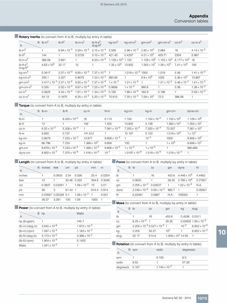
10/15Siemens NC 82 · 2015
AppendixConversion tables
10
■ Rotary inertia (to convert from A to B, multiply by entry in table)
■ Torque (to convert from A to B, multiply by entry in table)
■ Length (to convert from A to B, multiply by entry in table)
■ Power (to convert from A to B, multiply by entry in table)
■ Force (to convert from A to B, multiply by entry in table)
■ Mass (to convert from A to B, multiply by entry in table)
■ Rotation (to convert from A to B, multiply by entry in table)
BA
lb-in2 lb-ft2 lb-in-s2 lb-ft-s2
slug-ft2kg-cm2 kg-cm-s2 gm-cm2 gm-cm-s2 oz-in2 oz-in-s2
lb-in2 1 6.94 × 10⁻³ 2.59 × 10⁻³ 2.15 × 10⁻⁴ 2.926 2.98 × 10⁻³ 2.92 × 10³ 2.984 16 4.14 × 10⁻²
lb-ft2 144 1 0.3729 3.10 × 10⁻² 421.40 0.4297 4.21 × 10⁵ 429.71 2304 5.967
lb-in-s2 386.08 2.681 1 8.33 × 10⁻² 1.129 × 10³ 1.152 1.129 × 10⁶ 1.152 × 10³ 6.177 × 10³ 16
lb-ft-s2
slug-ft24.63 × 103 32.17 12 1 1.35 × 10⁴ 13.825 1.355 × 10⁷ 1.38 × 10⁴ 7.41 × 10⁴ 192
kg-cm2 0.3417 2.37 × 10⁻³ 8.85 × 10⁻⁴ 7.37 × 10⁻⁵ 1 1.019 × 10⁻³ 1000 1.019 5.46 1.41 × 10⁻²
kg-cm-s2 335.1 2.327 0.8679 7.23 × 10⁻² 980.66 1 9.8 × 10⁵ 1000 5.36 × 10³ 13.887
gm-cm2 3.417 × 10⁻⁴ 2.37 × 10⁻⁶ 8.85 × 10⁻⁷ 7.37 × 10⁻⁸ 1 × 10⁻³ 1.01 × 10⁻⁶ 1 1.01 × 10⁻³ 5.46 × 10⁻³ 1.41 × 10⁻⁵
gm-cm-s2 0.335 2.32 × 10⁻³ 8.67 × 10⁻⁴ 7.23 × 10⁻⁵ 0.9806 1 × 10⁻³ 980.6 1 5.36 1.38 × 10⁻²
oz-in2 0.0625 4.34 × 10⁻⁴ 1.61 × 10⁻⁴ 1.34 × 10⁻⁵ 0.182 1.86 × 10⁻⁴ 182.9 0.186 1 2.59 × 10⁻³
oz-in-s2 24.13 0.1675 6.25 × 10⁻² 5.20 × 10⁻³ 70.615 7.20 × 10⁻² 7.09 × 10⁴ 72.0 386.08 1
BA
lb-in lb-ft oz-in N-m kg-cm kg-m gm-cm dyne-cm
lb-in 1 8.333 × 10⁻² 16 0.113 1.152 1.152 × 10⁻² 1.152 × 10³ 1.129 × 10⁶
lb-ft 12 1 192 1.355 13.825 0.138 1.382 × 10⁴ 1.355 × 10⁷
oz-in 6.25 × 10⁻² 5.208 × 10⁻³ 1 7.061 × 10⁻³ 7.200 × 10⁻² 7.200 × 10⁻⁴ 72.007 7.061 × 10⁴
N-m 8.850 0.737 141.612 1 10.197 0.102 1.019 × 10⁴ 1 × 10⁷
kg-cm 0.8679 7.233 × 10⁻² 13.877 9.806 × 10⁻² 1 10–2 1000 9.806 × 10⁵
kg-m 86.796 7.233 1.388 × 10³ 9.806 100 1 1 × 10⁵ 9.806 × 10⁷
gm-cm 8.679 × 10⁻⁴ 7.233 × 10⁻⁵ 1.388 × 10⁻² 9.806 × 10⁻⁵ 1 × 10⁻³ 1 × 10⁻⁵ 1 980.665
dyne-cm 8.850 × 10⁻⁷ 7.375 × 10⁻⁸ 1.416 × 10⁻⁵ 10–7 1.0197 × 10⁻⁶ 1.019 × 10⁻⁸ 1.019 × 10⁻³ 1
BA
inches feet cm yd mm m
inches 1 0.0833 2.54 0.028 25.4 0.0254
feet 12 1 30.48 0.333 304.8 0.3048
cm 0.3937 0.03281 1 1.09 × 10⁻² 10 0.01
yd 36 3 91.44 1 914.4 0.914
mm 0.03937 0.00328 0.1 1.09 × 10⁻³ 1 0.001
m 39.37 3.281 100 1.09 1000 1
BA
hp Watts
hp (English) 1 745.7
(lb-in) (deg./s) 2.645 × 10⁻⁶ 1.972 × 10⁻³
(lb-in) (rpm) 1.587 × 10⁻⁵ 1.183 × 10⁻²
(lb-ft) (deg./s) 3.173 × 10⁻⁵ 2.366 × 10⁻²
(lb-ft) (rpm) 1.904 × 10⁻⁴ 0.1420
Watts 1.341 × 10⁻³ 1
BA
lb oz gm dyne N
lb 1 16 453.6 4.448 × 10⁵ 4.4482
oz 0.0625 1 28.35 2.780 × 10⁴ 0.27801
gm 2.205 × 10⁻³ 0.03527 1 1.02 × 10⁻³ N.A.
dyne 2.248 × 10⁻⁶ 3.59 × 10⁻⁵ 980.7 1 0.00001
N 0.22481 3.5967 N.A. 100000 1
BA
lb oz gm kg slug
lb 1 16 453.6 0.4536 0.0311
oz 6.25 × 10⁻² 1 28.35 0.02835 1.93 × 10⁻³
gm 2.205 × 10⁻³ 3.527 × 10⁻² 1 10–3 6.852 × 10⁻⁵
kg 2.205 35.27 103 1 6.852 × 10⁻²
slug 32.17 514.8 1.459 × 10⁴ 14.59 1
BA
rpm rad/s degrees/s
rpm 1 0.105 6.0
rad/s 9.55 1 57.30
degrees/s 0.167 1.745 × 10⁻² 1
© Siemens AG 2015
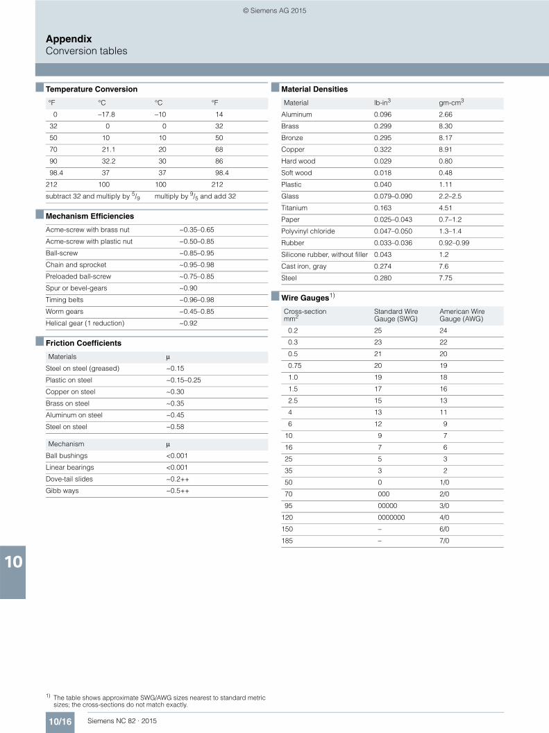
10/16 Siemens NC 82 · 2015
AppendixConversion tables
10
■ Temperature Conversion
■ Mechanism Efficiencies
■ Friction Coefficients
1) The table shows approximate SWG/AWG sizes nearest to standard metric sizes; the cross-sections do not match exactly.
■ Material Densities
■ Wire Gauges1)
°F °C °C °F
0 –17.8 –10 14
32 0 0 32
50 10 10 50
70 21.1 20 68
90 32.2 30 86
98.4 37 37 98.4
212 100 100 212
subtract 32 and multiply by 5/9 multiply by 9/5 and add 32
Acme-screw with brass nut ~0.35–0.65
Acme-screw with plastic nut ~0.50–0.85
Ball-screw ~0.85–0.95
Chain and sprocket ~0.95–0.98
Preloaded ball-screw ~0.75–0.85
Spur or bevel-gears ~0.90
Timing belts ~0.96–0.98
Worm gears ~0.45–0.85
Helical gear (1 reduction) ~0.92
Materials μ
Steel on steel (greased) ~0.15
Plastic on steel ~0.15–0.25
Copper on steel ~0.30
Brass on steel ~0.35
Aluminum on steel ~0.45
Steel on steel ~0.58
Mechanism μ
Ball bushings <0.001
Linear bearings <0.001
Dove-tail slides ~0.2++
Gibb ways ~0.5++
Material lb-in3 gm-cm3
Aluminum 0.096 2.66
Brass 0.299 8.30
Bronze 0.295 8.17
Copper 0.322 8.91
Hard wood 0.029 0.80
Soft wood 0.018 0.48
Plastic 0.040 1.11
Glass 0.079–0.090 2.2–2.5
Titanium 0.163 4.51
Paper 0.025–0.043 0.7–1.2
Polyvinyl chloride 0.047–0.050 1.3–1.4
Rubber 0.033–0.036 0.92–0.99
Silicone rubber, without filler 0.043 1.2
Cast iron, gray 0.274 7.6
Steel 0.280 7.75
Cross-sectionmm2
Standard WireGauge (SWG)
American WireGauge (AWG)
0.2 25 24
0.3 23 22
0.5 21 20
0.75 20 19
1.0 19 18
1.5 17 16
2.5 15 13
4 13 11
6 12 9
10 9 7
16 7 6
25 5 3
35 3 2
50 0 1/0
70 000 2/0
95 00000 3/0
120 0000000 4/0
150 – 6/0
185 – 7/0
© Siemens AG 2015
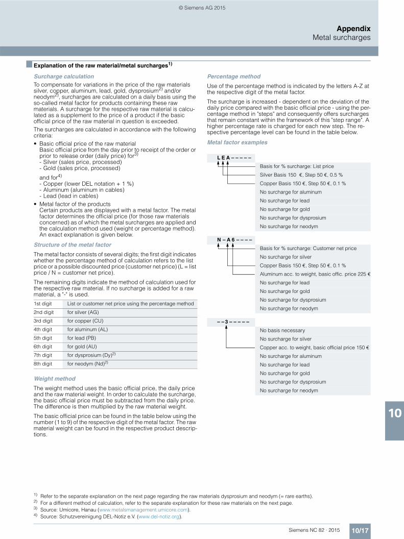
10/17Siemens NC 82 · 2015
AppendixMetal surcharges
10
■ Explanation of the raw material/metal surcharges1) 2) 3) 4)
Surcharge calculationTo compensate for variations in the price of the raw materials silver, copper, aluminum, lead, gold, dysprosium2) and/or neodym2), surcharges are calculated on a daily basis using the so-called metal factor for products containing these raw materials. A surcharge for the respective raw material is calcu-lated as a supplement to the price of a product if the basic official price of the raw material in question is exceeded.The surcharges are calculated in accordance with the following criteria:• Basic official price of the raw material
Basic official price from the day prior to receipt of the order or prior to release order (daily price) for3)
- Silver (sales price, processed) - Gold (sales price, processed)
and for4)
- Copper (lower DEL notation + 1 %)- Aluminum (aluminum in cables) - Lead (lead in cables)
• Metal factor of the productsCertain products are displayed with a metal factor. The metal factor determines the official price (for those raw materials concerned) as of which the metal surcharges are applied and the calculation method used (weight or percentage method). An exact explanation is given below.
Structure of the metal factor
The metal factor consists of several digits; the first digit indicates whether the percentage method of calculation refers to the list price or a possible discounted price (customer net price) (L = list price / N = customer net price).
The remaining digits indicate the method of calculation used for the respective raw material. If no surcharge is added for a raw material, a "-" is used.
Weight method
The weight method uses the basic official price, the daily price and the raw material weight. In order to calculate the surcharge, the basic official price must be subtracted from the daily price. The difference is then multiplied by the raw material weight.
The basic official price can be found in the table below using the number (1 to 9) of the respective digit of the metal factor. The raw material weight can be found in the respective product descrip-tions.
Percentage method
Use of the percentage method is indicated by the letters A-Z at the respective digit of the metal factor.
The surcharge is increased - dependent on the deviation of the daily price compared with the basic official price - using the per-centage method in "steps" and consequently offers surcharges that remain constant within the framework of this "step range". A higher percentage rate is charged for each new step. The re-spective percentage level can be found in the table below.
Metal factor examples
1) Refer to the separate explanation on the next page regarding the raw materials dysprosium and neodym (= rare earths).2) For a different method of calculation, refer to the separate explanation for these raw materials on the next page.3) Source: Umicore, Hanau (www.metalsmanagement.umicore.com).4) Source: Schutzvereinigung DEL-Notiz e.V. (www.del-notiz.org).
1st digit List or customer net price using the percentage method
2nd digit for silver (AG)
3rd digit for copper (CU)
4th digit for aluminum (AL)
5th digit for lead (PB)
6th digit for gold (AU)
7th digit for dysprosium (Dy)2)
8th digit for neodym (Nd)2)
L E A – – – – –
Basis for % surcharge: List price
Silver Basis 150 €, Step 50 €, 0.5 %
Copper Basis 150 €, Step 50 €, 0.1 %
No surcharge for aluminum
No surcharge for lead
No surcharge for gold
No surcharge for dysprosium
No surcharge for neodym
N – A 6 – – – –
Basis for % surcharge: Customer net price
No surcharge for silver
Copper Basis 150 €, Step 50 €, 0.1 %
Aluminum acc. to weight, basic offic. price 225 €
No surcharge for lead
No surcharge for gold
No surcharge for dysprosium
No surcharge for neodym
– – 3 – – – – –
No basis necessary
No surcharge for silver
Copper acc. to weight, basic official price 150 €
No surcharge for aluminum
No surcharge for lead
No surcharge for gold
No surcharge for dysprosium
No surcharge for neodym
© Siemens AG 2015
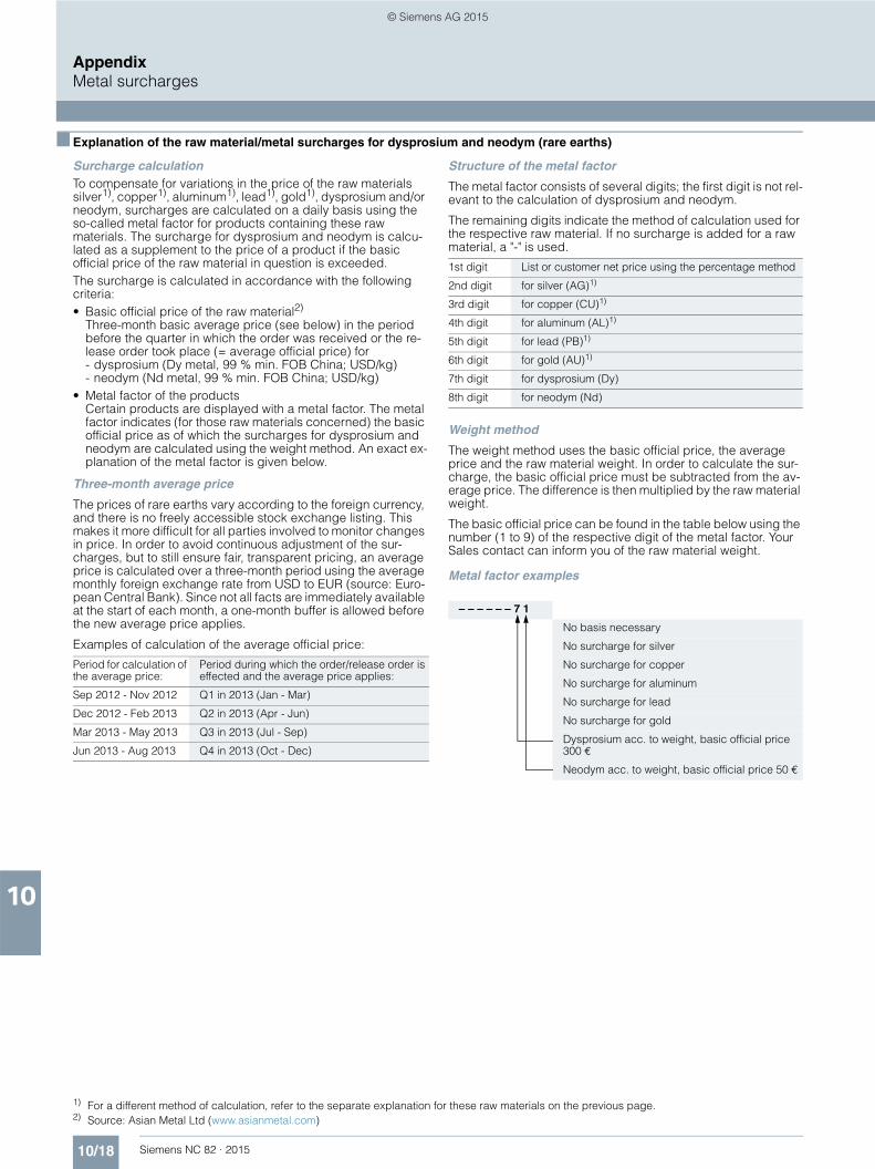
10/18 Siemens NC 82 · 2015
AppendixMetal surcharges
10
■ Explanation of the raw material/metal surcharges for dysprosium and neodym (rare earths)1) 2)
Surcharge calculationTo compensate for variations in the price of the raw materials silver1), copper1), aluminum1), lead1), gold1), dysprosium and/or neodym, surcharges are calculated on a daily basis using the so-called metal factor for products containing these raw materials. The surcharge for dysprosium and neodym is calcu-lated as a supplement to the price of a product if the basic official price of the raw material in question is exceeded.The surcharge is calculated in accordance with the following criteria:• Basic official price of the raw material2)
Three-month basic average price (see below) in the period before the quarter in which the order was received or the re-lease order took place (= average official price) for- dysprosium (Dy metal, 99 % min. FOB China; USD/kg)- neodym (Nd metal, 99 % min. FOB China; USD/kg)
• Metal factor of the productsCertain products are displayed with a metal factor. The metal factor indicates (for those raw materials concerned) the basic official price as of which the surcharges for dysprosium and neodym are calculated using the weight method. An exact ex-planation of the metal factor is given below.
Three-month average price
The prices of rare earths vary according to the foreign currency, and there is no freely accessible stock exchange listing. This makes it more difficult for all parties involved to monitor changes in price. In order to avoid continuous adjustment of the sur-charges, but to still ensure fair, transparent pricing, an average price is calculated over a three-month period using the average monthly foreign exchange rate from USD to EUR (source: Euro-pean Central Bank). Since not all facts are immediately available at the start of each month, a one-month buffer is allowed before the new average price applies.
Examples of calculation of the average official price:
Structure of the metal factor
The metal factor consists of several digits; the first digit is not rel-evant to the calculation of dysprosium and neodym.
The remaining digits indicate the method of calculation used for the respective raw material. If no surcharge is added for a raw material, a "-" is used.
Weight method
The weight method uses the basic official price, the average price and the raw material weight. In order to calculate the sur-charge, the basic official price must be subtracted from the av-erage price. The difference is then multiplied by the raw material weight.
The basic official price can be found in the table below using the number (1 to 9) of the respective digit of the metal factor. Your Sales contact can inform you of the raw material weight.
Metal factor examples
1) For a different method of calculation, refer to the separate explanation for these raw materials on the previous page.2) Source: Asian Metal Ltd (www.asianmetal.com)
Period for calculation of the average price:
Period during which the order/release order is effected and the average price applies:
Sep 2012 - Nov 2012 Q1 in 2013 (Jan - Mar)
Dec 2012 - Feb 2013 Q2 in 2013 (Apr - Jun)
Mar 2013 - May 2013 Q3 in 2013 (Jul - Sep)
Jun 2013 - Aug 2013 Q4 in 2013 (Oct - Dec)
1st digit List or customer net price using the percentage method
2nd digit for silver (AG)1)
3rd digit for copper (CU)1)
4th digit for aluminum (AL)1)
5th digit for lead (PB)1)
6th digit for gold (AU)1)
7th digit for dysprosium (Dy)
8th digit for neodym (Nd)
– – – – – – 7 1
No basis necessary
No surcharge for silver
No surcharge for copper
No surcharge for aluminum
No surcharge for lead
No surcharge for gold
Dysprosium acc. to weight, basic official price 300 €
Neodym acc. to weight, basic official price 50 €
© Siemens AG 2015

10/19Siemens NC 82 · 2015
AppendixMetal surcharges
10
■ Values of the metal factor
Percentage method
Basic official pricein €
Step range in €
% surcharge1st step
% surcharge2nd step
% surcharge3rd step
% surcharge4th step
% sur-charge
per addi-tional stepPrice in € Price in € Price in € Price in €
150.01 - 200.00 200.01 - 250.00 250.01 - 300.00 300.01 - 350.00
A 150 50 0.1 0.2 0.3 0.4 0.1
B 150 50 0.2 0.4 0.6 0.8 0.2
C 150 50 0.3 0.6 0.9 1.2 0.3
D 150 50 0.4 0.8 1.2 1.6 0.4
E 150 50 0.5 1.0 1.5 2.0 0.5
F 150 50 0.6 1.2 1.8 2.4 0.6
G 150 50 1.0 2.0 3.0 4.0 1.0
H 150 50 1.2 2.4 3.6 4.8 1.2
I 150 50 1.6 3.2 4.8 6.4 1.6
J 150 50 1.8 3.6 5.4 7.2 1.8
175.01 - 225.00 225.01 - 275.00 275.01 - 325.00 325.01 - 375.00
O 175 50 0.1 0.2 0.3 0.4 0.1
P 175 50 0.2 0.4 0.6 0.8 0.2
R 175 50 0.5 1.0 1.5 2.0 0.5
225.01 - 275.00 275.01 - 325.00 325.01 - 375.00 375.01 - 425.00
S 225 50 0.2 0.4 0.6 0.8 0.2
U 225 50 1.0 2.0 3.0 4.0 1.0
V 225 50 1.0 1.5 2.0 3.0 1.0
W 225 50 1.2 2.5 3.5 4.5 1.0
150.01 - 175.00 175.01 - 200.00 200.01 - 225.00 225.01 - 250.00
Y 150 25 0.3 0.6 0.9 1.2 0.3
400.01 - 425.00 425.01 - 450.00 450.01 - 475.00 475.01 - 500.00
Z 400 25 0.1 0.2 0.3 0.4 0.1
Price basis (1st digit)
L Calculation based on the list price
N Calculation based on the customer net price (discounted list price)
Weight method
Basic official price in €
1 50
Calculation based on raw material weight
2 100
3 150
4 175
5 200
6 225
7 300
8 400
9 555
Miscella-neous
- No metal surcharge
© Siemens AG 2015
10/20 Siemens NC 82 · 2015
AppendixConditions of sale and delivery/Export regulations
10
■ 1. General Provisions
By using this catalog you can acquire hardware and software products described therein from Siemens AG subject to the following Terms and Conditions of Sale and Delivery (hereinafter referred to as "T&C"). Please note that the scope, the quality and the conditions for supplies and services, including software products, by any Siemens entity having a registered office outside Germany, shall be subject exclusively to the General Terms and Conditions of the respective Siemens entity. The following T&C apply exclusively for orders placed with Siemens Aktiengesellschaft, Germany.
1.1 For customers with a seat or registered office in GermanyFor customers with a seat or registered office in Germany, the following applies subordinate to the T&C:• the "General Terms of Payment"1) and,• for software products, the "General License Conditions for
Software Products for Automation and Drives for Customers with a Seat or Registered Office in Germany"1) and,
• for other supplies and services, the "General Conditions for the Supply of Products and Services of the Electrical and Electronics Industry"1).
1.2 For customers with a seat or registered office outside GermanyFor customers with a seat or registered office outside Germany, the following applies subordinate to the T&C:• the "General Terms of Payment"1) and,• for software products, the "General License Conditions for
Software Products for Automation and Drives for Customers with a Seat or Registered Office outside of Germany"1) and
• for other supplies and/or services, the "General Conditions for Supplies of Siemens Industry for Customers with a Seat or Registered Office outside of Germany"1).
■ 2. Prices
The prices are in € (Euro) ex point of delivery, exclusive of packaging.The sales tax (value added tax) is not included in the prices. It shall be charged separately at the respective rate according to the applicable statutory legal regulations.Prices are subject to change without prior notice. We will charge the prices valid at the time of delivery.To compensate for variations in the price of raw materials (e.g. silver, copper, aluminum, lead, gold, dysprosium and neodym), surcharges are calculated on a daily basis using the so-called metal factor for products containing these raw materials. A surcharge for the respective raw material is calculated as a supplement to the price of a product if the basic official price of the raw material in question is exceeded.The metal factor of a product indicates the basic official price (for those raw materials concerned) as of which the surcharges on the price of the product are applied, and with what method of calculation. You will find a detailed explanation of the metal factor on the page headed "Metal surcharges".To calculate the surcharge (except in the cases of dysprosium and neodym), the official price from the day prior to that on which the order was received or the release order was effected is used.To calculate the surcharge applicable to dysprosium and neodym ("rare earths"), the corresponding three-month basic average price in the quarter prior to that in which the order was received or the release order was effected is used with a one-month buffer (details on the calculation can be found in the explanation of the metal factor).
■ 3. Additional Terms and Conditions
The dimensions are in mm. In Germany, according to the German law on units in measuring technology, data in inches apply only to devices for export.Illustrations are not binding.Insofar as there are no remarks on the individual pages of this catalog - especially with regard to data, dimensions and weights given - these are subject to change without prior notice.
■ 4. Export regulations
We shall not be obligated to fulfill any agreement if such fulfillment is prevented by any impediments arising out of national or international foreign trade or customs requirements or any embargoes and/or other sanctions.Export of goods listed in this catalog may be subject to licensing requirements. We will indicate in the delivery details whether licenses are required under German, European and US export lists. Goods labeled with "AL" not equal to "N" are subject to European or German export authorization when being exported out of the EU. Goods labeled with "ECCN" not equal to "N" are subject to US re-export authorization. The export indications can be viewed in advance in the description of the respective goods on the Industry Mall, our online catalog system. Only the export labels "AL" and "ECCN" indicated on order confirmations, delivery notes and invoices are authoritative.Even without a label, or with label "AL:N" or "ECCN:N", authori-zation may be required i.a. due to the final disposition and intended use of goods.If you transfer goods (hardware and/or software and/or technology as well as corresponding documentation, regardless of the mode of provision) delivered by us or works and services (including all kinds of technical support) performed by us to a third party worldwide, you must comply with all applicable national and international (re-)export control regulations.If required for the purpose of conducting export control checks, you (upon request by us) shall promptly provide us with all infor-mation pertaining to the particular end customer, final dispo-sition and intended use of goods delivered by us respectively works and services provided by us, as well as to any export control restrictions existing in this relation.The products listed in this catalog may be subject to European/German and/or US export regulations. Any export requiring approval is therefore subject to authorization by the relevant authorities.Errors excepted and subject to change without prior notice.
1) The text of the Terms and Conditions of Siemens AG can be downloaded atwww.siemens.com/automation/salesmaterial-as/catalog/en/ terms_of_trade_en.pdf
© Siemens AG 2015
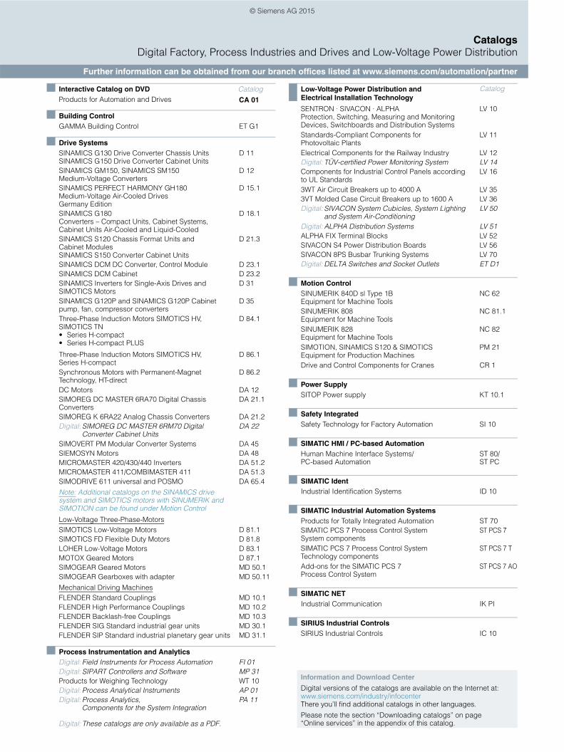
CatalogsDigital Factory, Process Industries and Drives and Low-Voltage Power Distribution
Further information can be obtained from our branch offices listed at www.siemens.com/automation/partner
Interactive Catalog on DVD CatalogProducts for Automation and Drives CA 01
Building ControlGAMMA Building Control ET G1
Drive SystemsSINAMICS G130 Drive Converter Chassis Units SINAMICS G150 Drive Converter Cabinet Units
D 11
SINAMICS GM150, SINAMICS SM150 Medium-Voltage Converters
D 12
SINAMICS PERFECT HARMONY GH180 Medium-Voltage Air-Cooled Drives Germany Edition
D 15.1
SINAMICS G180 Converters – Compact Units, Cabinet Systems, Cabinet Units Air-Cooled and Liquid-Cooled
D 18.1
SINAMICS S120 Chassis Format Units and Cabinet Modules SINAMICS S150 Converter Cabinet Units
D 21.3
SINAMICS DCM DC Converter, Control Module D 23.1SINAMICS DCM Cabinet D 23.2SINAMICS Inverters for Single-Axis Drives and SIMOTICS Motors
D 31
SINAMICS G120P and SINAMICS G120P Cabinet pump, fan, compressor converters
D 35
Three-Phase Induction Motors SIMOTICS HV, SIMOTICS TN• Series H-compact• Series H-compact PLUS
D 84.1
Three-Phase Induction Motors SIMOTICS HV, Series H-compact
D 86.1
Synchronous Motors with Permanent-Magnet Technology, HT-direct
D 86.2
DC Motors DA 12SIMOREG DC MASTER 6RA70 Digital Chassis Converters
DA 21.1
SIMOREG K 6RA22 Analog Chassis Converters DA 21.2Digital: SIMOREG DC MASTER 6RM70 Digital
Converter Cabinet UnitsDA 22
SIMOVERT PM Modular Converter Systems DA 45SIEMOSYN Motors DA 48MICROMASTER 420/430/440 Inverters DA 51.2MICROMASTER 411/COMBIMASTER 411 DA 51.3SIMODRIVE 611 universal and POSMO DA 65.4
Note: Additional catalogs on the SINAMICS drive system and SIMOTICS motors with SINUMERIK and SIMOTION can be found under Motion Control
Low-Voltage Three-Phase-MotorsSIMOTICS Low-Voltage Motors D 81.1SIMOTICS FD Flexible Duty Motors D 81.8LOHER Low-Voltage Motors D 83.1MOTOX Geared Motors D 87.1SIMOGEAR Geared Motors MD 50.1SIMOGEAR Gearboxes with adapter MD 50.11
Mechanical Driving MachinesFLENDER Standard Couplings MD 10.1FLENDER High Performance Couplings MD 10.2FLENDER Backlash-free Couplings MD 10.3FLENDER SIG Standard industrial gear units MD 30.1FLENDER SIP Standard industrial planetary gear units MD 31.1
Process Instrumentation and AnalyticsDigital: Field Instruments for Process Automation FI 01Digital: SIPART Controllers and Software MP 31Products for Weighing Technology WT 10Digital: Process Analytical Instruments AP 01Digital: Process Analytics,
Components for the System IntegrationPA 11
Digital: These catalogs are only available as a PDF.
Low-Voltage Power Distribution and Electrical Installation Technology
Catalog
SENTRON · SIVACON · ALPHA Protection, Switching, Measuring and Monitoring Devices, Switchboards and Distribution Systems
LV 10
Standards-Compliant Components for Photovoltaic Plants
LV 11
Electrical Components for the Railway Industry LV 12Digital: TÜV-certified Power Monitoring System LV 14Components for Industrial Control Panels according to UL Standards
LV 16
3WT Air Circuit Breakers up to 4000 A LV 353VT Molded Case Circuit Breakers up to 1600 A LV 36Digital: SIVACON System Cubicles, System Lighting
and System Air-ConditioningLV 50
Digital: ALPHA Distribution Systems LV 51ALPHA FIX Terminal Blocks LV 52SIVACON S4 Power Distribution Boards LV 56SIVACON 8PS Busbar Trunking Systems LV 70Digital: DELTA Switches and Socket Outlets ET D1
Motion ControlSINUMERIK 840D sl Type 1B Equipment for Machine Tools
NC 62
SINUMERIK 808 Equipment for Machine Tools
NC 81.1
SINUMERIK 828 Equipment for Machine Tools
NC 82
SIMOTION, SINAMICS S120 & SIMOTICS Equipment for Production Machines
PM 21
Drive and Control Components for Cranes CR 1
Power SupplySITOP Power supply KT 10.1
Safety IntegratedSafety Technology for Factory Automation SI 10
SIMATIC HMI / PC-based AutomationHuman Machine Interface Systems/PC-based Automation
ST 80/ ST PC
SIMATIC IdentIndustrial Identification Systems ID 10
SIMATIC Industrial Automation SystemsProducts for Totally Integrated Automation ST 70SIMATIC PCS 7 Process Control System System components
ST PCS 7
SIMATIC PCS 7 Process Control System Technology components
ST PCS 7 T
Add-ons for the SIMATIC PCS 7 Process Control System
ST PCS 7 AO
SIMATIC NETIndustrial Communication IK PI
SIRIUS Industrial Controls SIRIUS Industrial Controls IC 10
Information and Download Center
Digital versions of the catalogs are available on the Internet at:www.siemens.com/industry/infocenter There you’ll find additional catalogs in other languages.
Please note the section “Downloading catalogs” on page “Online services” in the appendix of this catalog.
© Siemens AG 2015

Get more information
SINUMERIK automation systems for machine tools:www.siemens.com/sinumerik
The drives family SINAMICS:www.siemens.com/sinamics
Motion Control Systems and Motion Control Solutions for production machine and machine tool equipment:www.siemens.com/motioncontrol
Local partners worldwide:www.siemens.com/automation/partner
The information provided in this catalog contains merely general descriptions or characteristics of performance which in case of actual use do not always apply as described or which may change as a result of further development of the products. An obligation to provide the respective characteristics shall only exist if expressly agreed in the terms of contract. Availability and technical specifications are subject to change without notice. All product designations may be trademarks or product names of Siemens AG or supplier companies whose use by third parties for their own purposes could violate the rights of the owners.
Token fee: 3.00 €
Siemens AGDigital FactoryMotion ControlPostfach 318091050 ERLANGENGERMANY
Subject to change without prior noticeArticle No. E86060-K4482-A101-A4-7600E.9114.88.VKT / Dispo 09400KG 0915 1. HOF 220 EnPrinted in Germany © Siemens AG 2015
www.siemens.com/automation
Security information
Siemens provides products and solutions with industrial security functions that support the secure operation of plants, solutions, machines, equipment and/or networks. They are important components in a holistic industrial security concept. With this in mind, Siemens’ products and solutions undergo continuous development. Siemens recommends strongly that you regularly check for product updates.
For the secure operation of Siemens products and solutions, it is necessary to take suitable preventive action (e.g. cell protection concept) and integrate each component into a holistic, state-of-the-art industrial security concept. Third-party products that may be in use should also be considered. For more information about industrial security, visit www.siemens.com/industrialsecurity
To stay informed about product updates as they occur, sign up for a product-specific newsletter. For more information, visit http://support.automation.siemens.com
© Siemens AG 2015