catalog ik pi 2015, englishb85470b6-efa0... · 5/2 siemens ik pi · 2015 io-link introduction...
TRANSCRIPT
Siemens IK PI · 2015
55/2 Introduction5/2 Communication overview
5/3 System components
5/8 IO-Link specification
5/9 Masters
5/9 IO-Link master module for S7-12005/9 - SM 1278 4xIO-Link master
5/10 IO-Link master module for ET 200SP5/10 - CM 4xIO-Link
5/12 IO-Link master modules for ET 200S
5/12 - IO-Link 4SI electronic modules
5/13 - SIRIUS 4SI electronic modules
5/14 IO-Link master modules for ET 200eco PN
5/15 Input modules
5/15 General data5/16 IO-Link K20 modules
5/18 Contactors and contactor assemblies
5/18 SIRIUS 3RT20 contactors, 3-pole, 3 ... 18.5 kW
5/20 SIRIUS 3RA23 reversing contactor assemblies
5/22 SIRIUS 3RA24 contactor assembliesfor wye-delta starting
5/24 SIRIUS 3RA27 function module for IO-Link
5/26 SIRIUS 3RB24 solid-state overload relays for IO-Link
5/26 3RB24 for IO-Link, up to 630 Afor High-Feature applications
5/30 Current measuring modules
5/31 Accessories
5/33 SIRIUS 3RA6 compact starters
5/33 SIRIUS 3RA64, 3RA65 compact startersfor IO-Link
5/35 Accessories for compact startersfor IO-Link
5/36 SIRIUS 3RR24 monitoring relays for mounting onto 3RT2 contactorsfor IO-Link
5/36 General data
5/39 Current and active current monitoring
5/43 SIRIUS 3UG48 monitoring relays for stand-alone installationfor IO-Link
5/43 General data
5/46 Line monitoring
5/47 Voltage monitoring
5/48 Current monitoring
5/49 Power factor and active current monitoring
Residual current monitoring
5/50 - Residual-current monitoring relays5/51 - 3UL23 residual-current transformers
5/52 Speed monitoring
5/53 Accessories
5/54 SIRIUS 3RS14, 3RS15 temperature monitoring relays for IO-Link
5/54 General data
5/56 Relays, digitally adjustable for 1 sensor
5/58 Relays, digitally adjustable for up to 3 sensors
5/59 Accessories
5/60 RFID systems
5/61 SIMATIC RF210R
5/63 SIMATIC RF220R
5/65 SIMATIC RF260R
IO-Link
IKPI_05_en.book Seite 1 Montag, 6. Oktober 2014 4:09 16
© Siemens AG 2014
5/2 Siemens IK PI · 2015
IO-LinkIntroduction
Communication overview
5
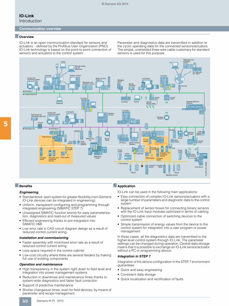
■ Overview
IO-Link is an open communication standard for sensors and actuators – defined by the Profibus User Organization (PNO). IO-Link technology is based on the point-to-point connection of sensors and actuators to the control system.
Parameter and diagnostics data are transmitted in addition to the cyclic operating data for the connected sensors/actuators. The simple, unshielded three-wire cable customary for standard sensors is used for this purpose.
■ Benefits
Engineering• Standardized, open system for greater flexibility (non-Siemens
IO-Link devices can be integrated in engineering)• Uniform, transparent configuring and programming through
integrated engineering (SIMATIC STEP 7)• Unassigned SIMATIC function blocks for easy parameteriza-
tion, diagnostics and read-out of measured values• Efficient engineering thanks to pre-integration into
SIMATIC HMI• Low error rate in CAD circuit diagram design as a result of
reduced control current wiring
Installation and commissioning• Faster assembly with minimized error rate as a result of
reduced control current wiring• Less space required in the control cabinet• Low-cost circuitry where there are several feeders by making
full use of existing components
Operation and maintenance• High transparency in the system right down to field level and
integration into power management systems• Reduction in downtimes and maintenance times thanks to
system-wide diagnostics and faster fault correction• Support of predictive maintenance• Shorter changeover times, even for field devices, by means of
parameter and recipe management
■ Application
IO-Link can be used in the following main applications:• Easy connection of complex IO-Link sensors/actuators with a
large number of parameters and diagnostic data to the control system
• Replacement of sensor boxes for connecting binary sensors with the IO-Link input modules optimized in terms of cabling
• Optimized cable connection of switching devices to the control system
• Simple transmission of energy values from the device to the control system for integration into a user program or power management
In these cases, all the diagnostics data are transmitted to the higher-level control system through IO-Link. The parameter settings can be changed during operation. Central data storage means that it is possible to exchange an IO-Link sensor/actuator without a PC or programming device.
Integration in STEP 7
Integration of the device configuration in the STEP 7 environment guarantees: • Quick and easy engineering • Consistent data storage• Quick localization and rectification of faults
Control andmonitoring system
Telecontrol and substation control
Remote access, e.g. via teleservice
Control andmonitoring systemField device for
intrinsically safe area
Coupler
Field devices
Code reading systems
RFID system
Telecontrol and substation control
Compactstarter
Compactstarter
Compactfeeder
Field devices
Field device
Power supply
Signalling column
Powersupply
Code reading
systems
IO-Linkmaster RFID
system
S7-1200 with CP�1242-7
Compactstarter
Protection and monitoring devices
Protection and monitoring devices
IO-Link module
IO-Link module
RFID system RFID system
PC/PG/IPC
Controller
Industrial Ethernet
PROFIBUSPROFIBUS PA
Laptop
Motion ControlSystems
Notebook
SINAMICS Drives
Numeric Control
MobilePanel
SIMOCODE pro
PROFINET
ASM456
Controller
PC/PG/IPC
Controller
Security
Link
Drives
PC/PG
Mobile Panel
IWLAN Controller
Database Server
DP-Slave Motion ControlSystems
ControllerLOGO!
Slaves Slaves
AS-Interface
Link
RF180C
AccessPoint
Link
Industrial EthernetSwitches
IWLANRCoax Cable
G_I
K10
_XX
_300
49
Controller Numeric Control
Controller
AccessPoint
ClientModule
PC
Wireless Devices
AccessPoint
IKPI_05_en.book Seite 2 Montag, 6. Oktober 2014 4:09 16
© Siemens AG 2014
5/3Siemens IK PI · 2015
IO-LinkIntroduction
System components
5
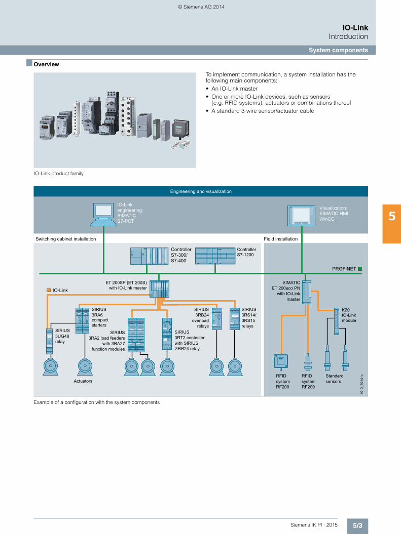
■ Overview
IO-Link product family
To implement communication, a system installation has the following main components: • An IO-Link master• One or more IO-Link devices, such as sensors
(e.g. RFID systems), actuators or combinations thereof• A standard 3-wire sensor/actuator cable
Example of a configuration with the system components
with SIRIUS 3RT2 contactorSIRIUS
Field installationSwitching cabinet installation
relaysoverload
3RB24 SIRIUS
S7-PCTSIMATIC engineering: IO-Link
WinCCSIMATIC HMI Visualization:
Engineering and visualization
ET 200SP (ET 200S)with IO-Link master
S7-400
Controller
RF200systemRFID
RF200systemRFID
sensorsStandard
moduleIO-Link K20
masterwith IO-Link
ET 200eco PN SIMATIC
relays3RS15 3RS14/SIRIUS
3RR24 relay
S7-300/
Actuators
3UG48relay
SIRIUS
compact starters
3RA6 SIRIUS
function moduleswith 3RA27
3RA2 load feeders SIRIUS
ControllerS7-1200
IK10
_301
41c
IO-Link
PROFINET
IKPI_05_en.book Seite 3 Montag, 6. Oktober 2014 4:09 16
© Siemens AG 2014

5/4 Siemens IK PI · 2015
IO-LinkIntroduction
System components
5
■ Overview (continued)
Compatibility of IO-Link
IO-Link guarantees compatibility between IO-Link-capable modules and standard modules as follows: • IO-Link sensors can be operated both on IO-Link modules
(masters) and standard input modules.• IO-Link sensors/actuators as well as today's standard sen-
sors/actuators can be used on IO-Link masters.• If conventional components are used in the IO-Link system,
then of course only the standard functions are available at this point.
Analog signals
Another advantage of IO-Link technology is that analog signals are digitized already in the IO-Link sensor itself and are digitally transmitted by the IO-Link communication. As the result, faults are prevented and there is no extra cost for cable shielding.
Enhanced through IO-Link input modules
IO-Link compatibility also permits connection of standard sensors/actuators, i.e. conventional sensors/actuators can also be connected to IO-Link. This is particularly effective with the IO-Link input modules, which allow several sensors to be con-nected at one time via a cable to the controller.
Load feeders and motor starters
Through IO-Link it is possible to control not only sensors but also actuators in the form of load feeders and motor starters.
Possibilities for connecting load feeders and motor starters to IO-Link or in the conventional way
Grouping of motor starters
The SIRIUS controls allow four starters to be combined to form a group.
Connection of a motor starter group made up of three 3RA64 direct-on-line starters and a 3RA65 reversing starter
In this way up to 16 starters can be operated on a single IO-Link master. This leads to a reduction in the installation space and control wiring required.
Sensors SensorsActuators Actuators
Point-to-pointconnection through IO-Link
Classicwiring
ET 200S/ET 200SPwith IO-Link master
ET 200S/ET 200SP with digital I/O modules
K20Sensorbox
NS
A0_
0048
9c
IKPI_05_en.book Seite 4 Montag, 6. Oktober 2014 4:09 16
© Siemens AG 2014
5/5Siemens IK PI · 2015
IO-LinkIntroduction
System components
5
■ Overview (continued)
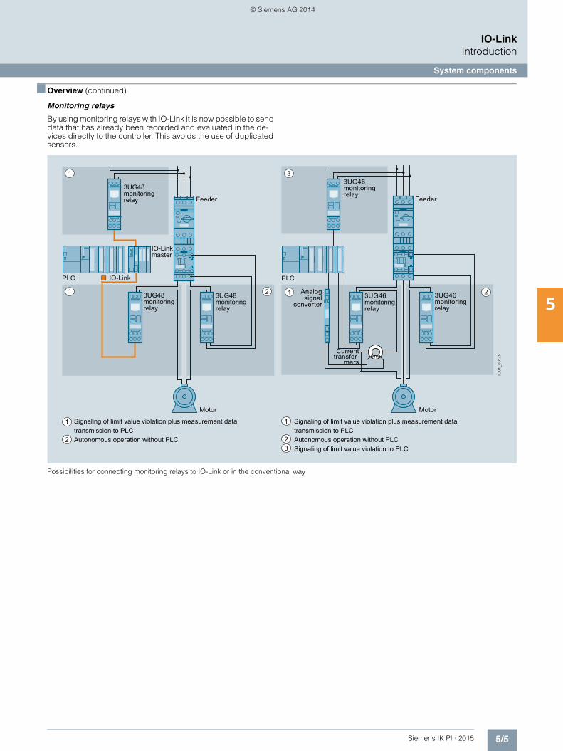
Monitoring relays
By using monitoring relays with IO-Link it is now possible to send data that has already been recorded and evaluated in the de-vices directly to the controller. This avoids the use of duplicated sensors.
Possibilities for connecting monitoring relays to IO-Link or in the conventional way
3
1 22
1
1
Feeder
PLC
Motor
3UG46monitoring relay
3UG46monitoring relay
3UG46monitoring relay
Analog signal
converter
Current transfor-
mers
Signaling of limit value violation plus measurement data transmission to PLCAutonomous operation without PLCSignaling of limit value violation to PLC
1
2
PLC
IO-Link master
3UG48monitoring relay
3UG48monitoring relay
3UG48monitoring relay Feeder
Motor
Signaling of limit value violation plus measurement data transmission to PLCAutonomous operation without PLC
1
23
IC01
_001
75
IO-Link
IKPI_05_en.book Seite 5 Montag, 6. Oktober 2014 4:09 16
© Siemens AG 2014

5/6 Siemens IK PI · 2015
IO-LinkIntroduction
System components
5
■ Overview (continued)
Wireless communication
Using an upstream IWLAN client module, such as SCALANCE W722-1 RJ45, allows IO-Link to be be integrated into the PROFINET world via a distributed I/O. Possible uses include acting as an alternative to fault-prone cable carrier or collector wire technology. The individual diagnostics options
offered by the various IO-Link devices provide greater transpar-ency for the production process. Just like the parameter data for a device, these diagnostics data can be evaluated remotely using the possibilities offered by SIMATIC. This supports remote maintenance down to the lowest level in the field.
Wireless communication between Industrial Ethernet and IO-Link components
ET 200SP (ET 200S)with IO-Link master
Pump station Maintenance station
Control room
3RA6 Compact starter
IC01
_001
98b
Industrial Ethernet
Industrial Ethernet
IO-Link
SCALANCE W722-1 RJ45
SIMATIC HMI KTP 1500 Basic
SIMATICS7-300
SCALANCE W786-1 RJ45 Access Point
IKPI_05_en.book Seite 6 Montag, 6. Oktober 2014 4:09 16
© Siemens AG 2014
5/7Siemens IK PI · 2015
IO-LinkIntroduction
System components
5
■ Overview (continued)
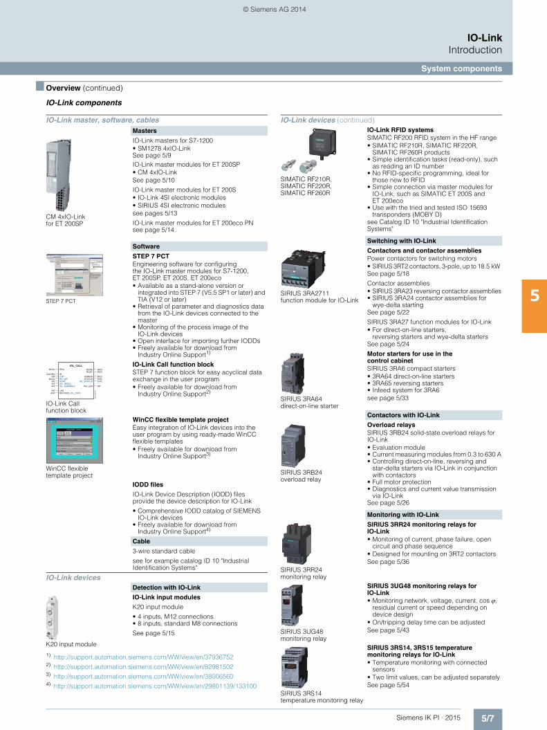
IO-Link components
1) http://support.automation.siemens.com/WW/view/en/37936752 2) http://support.automation.siemens.com/WW/view/en/82981502 3) http://support.automation.siemens.com/WW/view/en/38006560 4) http://support.automation.siemens.com/WW/view/en/29801139/133100
IO-Link master, software, cablesMasters
CM 4xIO-Link for ET 200SP
IO-Link masters for S7-1200• SM1278 4xIO-Link See page 5/9IO-Link master modules for ET 200SP• CM 4xIO-Link See page 5/10
IO-Link master modules for ET 200S • IO-Link 4SI electronic modules • SIRIUS 4SI electronic modules see pages 5/13
IO-Link master modules for ET 200eco PN see page 5/14.
Software
STEP 7 PCT
STEP 7 PCT Engineering software for configuring the IO-Link master modules for S7-1200, ET 200SP, ET 200S, ET 200eco• Available as a stand-alone version or
integrated into STEP 7 (V5.5 SP1 or later) and TIA (V12 or later)
• Retrieval of parameter and diagnostics data from the IO-Link devices connected to the master
• Monitoring of the process image of the IO-Link devices
• Open interface for importing further IODDs • Freely available for download from
Industry Online Support1)
IO-Link Call function block
IO-Link Call function blockSTEP 7 function block for easy acyclical data exchange in the user program• Freely available for download from
Industry Online Support2)
WinCC flexible template project
WinCC flexible template projectEasy integration of IO-Link devices into the user program by using ready-made WinCC flexible templates• Freely available for download from
Industry Online Support3)
IODD files
IO-Link Device Description (IODD) files provide the device description for IO-Link
• Comprehensive IODD catalog of SIEMENS IO-Link devices
• Freely available for download from Industry Online Support4)
Cable
3-wire standard cable
see for example catalog ID 10 "Industrial Identification Systems"
IO-Link devicesDetection with IO-Link
K20 input module
IO-Link input modules
K20 input module
• 4 inputs, M12 connections• 8 inputs, standard M8 connections
See page 5/15
BOOLIOL_CALL
DWORDINT
DONEBUSY
INTINTINT RD_LEN
INTANY
BOOLERROR
IOL_STATUSSTATUS
BOOLBOOL
INT
BOOL
DWODWO
REQ
IDCAP
PORTIOL_INDEXIOL_SUBINDEX
LENRECORD_IOL_DATA
RD_WR
IC01
_001
97
IO-Link devices (continued)
SIMATIC RF210R, SIMATIC RF220R, SIMATIC RF260R
IO-Link RFID systemsSIMATIC RF200 RFID system in the HF range• SIMATIC RF210R, SIMATIC RF220R,
SIMATIC RF260R products• Simple identification tasks (read-only), such
as reading an ID number• No RFID-specific programming, ideal for
those new to RFID• Simple connection via master modules for
IO-Link, such as SIMATIC ET 200S and ET 200eco
• Use with the tried and tested ISO 15693 transponders (MOBY D)
see Catalog ID 10 "Industrial Identification Systems"
Switching with IO-Link
SIRIUS 3RA2711 function module for IO-Link
Contactors and contactor assembliesPower contactors for switching motors• SIRIUS 3RT2 contactors, 3-pole, up to 18.5 kW See page 5/18
Contactor assemblies• SIRIUS 3RA23 reversing contactor assemblies• SIRIUS 3RA24 contactor assemblies for
wye-delta startingSee page 5/22
SIRIUS 3RA27 function modules for IO-Link• For direct-on-line starters,
reversing starters and wye-delta startersSee page 5/24
SIRIUS 3RA64 direct-on-line starter
Motor starters for use in the control cabinetSIRIUS 3RA6 compact starters• 3RA64 direct-on-line starters• 3RA65 reversing starters• Infeed system for 3RA6see page 5/33
Contactors with IO-Link
SIRIUS 3RB24 overload relay
Overload relaysSIRIUS 3RB24 solid-state overload relays for IO-Link• Evaluation module• Current measuring modules from 0.3 to 630 A• Controlling direct-on-line, reversing and
star-delta starters via IO-Link in conjunction with contactors
• Full motor protection• Diagnostics and current value transmission
via IO-LinkSee page 5/26
Monitoring with IO-Link
SIRIUS 3RR24 monitoring relay
SIRIUS 3RR24 monitoring relays for IO-Link• Monitoring of current, phase failure, open
circuit and phase sequence • Designed for mounting on 3RT2 contactorsSee page 5/36
SIRIUS 3UG48 monitoring relay
SIRIUS 3UG48 monitoring relays for IO-Link • Monitoring network, voltage, current, cos,
residual current or speed depending on device design
• On/tripping delay time can be adjustedSee page 5/43
SIRIUS 3RS14 temperature monitoring relay
SIRIUS 3RS14, 3RS15 temperature monitoring relays for IO-Link• Temperature monitoring with connected
sensors• Two limit values, can be adjusted separatelySee page 5/54
IKPI_05_en.book Seite 7 Montag, 6. Oktober 2014 4:09 16
© Siemens AG 2014

5/8 Siemens IK PI · 2015
IO-LinkIntroduction
IO-Link specification
5
■ Overview
Principles of the IO-Link specification
According to the IO-Link specification, communication functions as follows: • Transmission takes place via an unshielded three-wire cable
no more than 20 m long, of the kind normally used for standard sensors.
• Analog values which have already been digitized are transmit-ted in the form of message frames, which may correspond to 10 V or 4 to 20 mA.
• Digital communication from 0 to 24 V on the so-called C/Q cable
• Most of the values transmitted are measured values from the sensors which include the units.
• The sensors and actuators are described by the IO-Link Device Description (IODD).
• While the IO-Link specification permits an infinite number of ports, an IO-Link master currently only supports four ports. Only one IO-Link device (slave) can be connected to each port (point-to-point connection).
• The transmission rates between IO-Link master and the devices are as follows:- via COM1: 4 800 Bd - via COM2: 38 400 Bd - via COM3: 230 400 Bd
• The average cycle time is 2 ms for the reading/writing of 16 data bits at a transmission rate of 38 400 Bd.
IO-Link protocol
For the dialog between device and master, IO-Link uses a standard protocol, the standard asynchronous communication interface (UART) in "semi-duplex" mode.
The IO-Link protocol supports both the Standard IO mode (SIO) and the IO-Link communication mode (COM).
The structure of the protocol and its message frames depends on the types of data to be transmitted.
Data types
In the IO-Link specification a distinction is made between the fo-llowing data types:
Process data
The process data of the devices are transmitted cyclically in a data frame, provided the process data width does not exceed 2 bytes. In the case of larger process data widths up to 32 bytes, parts are transmitted one after the other in several cycles. As of Version 1.1 of the specification, up to 32 bytes of process data can be transferred in a single cycle.
Service data (SD)
With the aid of the service data, parameter values or device statuses can be read out. It is also possible to write the parame-ter values or transmit commands via the service data. Service data are always exchanged acyclically and in response to an inquiry from the IO-Link master.
Events
Via events it is possible to transmit device events or statuses such as contamination, overheating, short circuits etc., from the the device via the IO-Link master to the PLC or to visualize them.
The events are sent on the initiative of the devices via the "event flag", which the master evaluates. The master itself can also generate events.
Three categories of event are defined:• Error signals (errors)• Maintenance data (warnings)• Device functions (notifications)
Data storage
As of Specification V1.1, a data storage concept has been created for IO-Link. In this concept, the IO-Link device initiates the storage of its data on a higher-level parameter server. In the event that a device is replaced, the parameter server can restore the original parameterization. It is therefore possible to replace the devices without re-parameterization.
The IO-Link master can contain the parameter server. The parameter server can also be implemented centrally in the PLC or in a system server. In this case the IO-Link master passes on the corresponding information.
IO-Link master
The IO-Link master is the interface to higher-level control sys-tems. The IO-Link master presents itself as a normal fieldbus node, and is integrated into the appropriate network configurator via the relevant device description (e. g. GSD, FDCML, EDS etc.).
IO-Link Device Description (IODD)
The IO-Link Device Description (IODD) has been defined to provide a full, transparent description of system characteristics as far as the IO-Link device. It is based on the open XML standard.
The IODD contains information on communication characteris-tics, device parameters, identification, process and diagnostics data, and is supplied by the manufacturer. The design of the IODD is the same for all devices from all manufacturers, and is always presented in the same way by the IODD Interpreter Tools. This therefore ensures that the handling is the same for all IO-Link devices, whatever the manufacturer.
New in IO-Link Specification V1.1
The IO-Link Specification is currently available in Version 1.1, and standardized in accordance with IEC 61131-9.
Specification V1.1 offers the following new features compared with the previous Specification V1.0:• Transmission of up to 32 bytes of process or service data in
one cycle• Data storage concept
IO-Link master
Interface hardware:Compatible with sensors according to IEC 60947-5-2 and actuatorsCommunication and switching possible alternately
IO-Link device
SIOStandard IOswitching operation
SIO / IO-Link
COMSerial, bidirectional communication
IC01
_001
76
L+
C/Q
L–
41
23
IKPI_05_en.book Seite 8 Montag, 6. Oktober 2014 4:09 16
© Siemens AG 2014

5/9Siemens IK PI · 2015
IO-LinkMasters
IO-Link master module for S7-1200
SM 1278 4xIO-Link master
5
■ Overview
SM 1278 4xIO-Link master
The SM 1278 4xIO-Link master signal module is an IO-Link master, and can be used in the SIMATIC S7-1200 automation system.
Features• IO-Link master according to IO-Link specification V1.1• Up to four IO-Link devices (3-wire connections) can be
connected to each IO-Link master module. • Data transmission rates COM1 (4.8 kBd), COM2 (38.4 kBd),
COM3 (230.4 kBd), automatic adjustment to the transmission rate supported by the device
• Port-by-port parameterizable diagnostics• Up to eight IO-Link master modules can be used depending
on the SIMATIC S7-1200 CPU in use.
Central data storage
The device parameters are kept in the master module according to the specification V1.1.
Note:When the SM 1278 4xIO-Link master module is exchanged, the IO-Link parameter data are not assigned automatically.
Configuration
Module integration
To integrate the module you need the STEP 7 V13 TIA Portal engineering tool.
Configuration
S7-PCT V3.2 and higher is required in addition for IO-Link configuration.
PROFINET configuration with SIMATIC S7-1200 CPU and ET 200S distributed I/O with IO-Link master modules
The address areas for exchanging the cyclic data (process values) are defined by IO-Link in the device view of the PROFINET device.
Device view with setting of the address range by IO-Link via TIA Portal
■ Selection and ordering data
■ More information
For more information about SIMATIC S7-1200 see http://support.automation.siemens.com/WW/view/en/86567043.
Manuals
Manual "SIMATIC IO-Link System" see http://support.automation.siemens.com/WW/view/en/65949252.
Industry Mall
More information see Industry Mall at "Automation Technology" "Industrial Communication" "IO-Link" "Masters" "IO-Link Master Module for S7-1200"
Version Article No.
6ES7278-4BD32-0XB0
SM 1278 4xIO-Link master signal modules 6ES7278-4BD32-0XB0
• IO-Link master for SIMATIC S7-1200
• Corresponds to IO-Link specification V1.1
• Dimensions (W H D / mm): 45 100 75
• Up to eight IO-Link master modules can be used depending on the SIMATIC S7-1200 CPU in use.
• Firmware updates
IKPI_05_en.book Seite 9 Montag, 6. Oktober 2014 4:09 16
© Siemens AG 2014
5/10 Siemens IK PI · 2015
IO-LinkMastersIO-Link master module for ET 200SP
CM 4xIO-Link
5
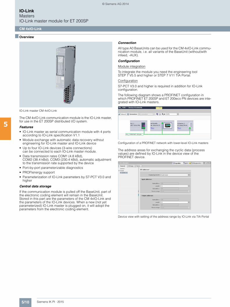
■ Overview
IO-Link master CM 4xIO-Link
The CM 4xIO-Link communication module is the IO-Link master, for use in the ET 200SP distributed I/O system.
Features• IO-Link master as serial communication module with 4 ports
according to IO-Link specification V1.1• Module exchange with automatic data recovery without
engineering for IO-Link master and IO-Link device• Up to four IO-Link devices (3-wire connections)
can be connected to each IO-Link master module. • Data transmission rates COM1 (4.8 kBd),
COM2 (38.4 kBd), COM3 (230.4 kBd), automatic adjustment to the transmission rate supported by the device
• Port-by-port parameterizable diagnostics• PROFIenergy support• Parameterization of IO-Link parameters by S7-PCT V3.0 and
higher
Central data storage
If the communication module is pulled off the BaseUnit, part of the electronic coding element will remain in the BaseUnit. Stored in this part are the parameters of the CM 4xIO-Link and the parameters of the IO-Link devices. When a new (not yet parameterized) IO-Link master is plugged on, it will adopt the parameters from the electronic coding element.
Connection
All type A0 BaseUnits can be used for the CM 4xIO-Link commu-nication module, i.e. all variants of the BaseUnit (without/with infeed, -AUX).
Configuration
Module integration
To integrate the module you need the engineering tool STEP 7 V5.5 and higher or STEP 7 V11 TIA Portal.
Configuration
S7-PCT V3.0 and higher is required in addition for IO-Link configuration.
The following diagram shows a PROFINET configuration in which PROFINET ET 200SP and ET 200eco PN devices are inte-grated with IO-Link masters.
Configuration of a PROFINET network with lower-level IO-Link masters
The address areas for exchanging the cyclic data (process values) are defined by IO-Link in the device view of the PROFINET device.
Device view with setting of the address range by IO-Link via TIA Portal
IKPI_05_en.book Seite 10 Montag, 6. Oktober 2014 4:09 16
© Siemens AG 2014
5/11Siemens IK PI · 2015
IO-LinkMasters
IO-Link master module for ET 200SP
CM 4xIO-Link
5
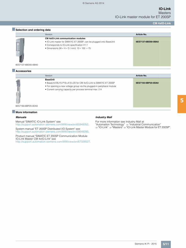
■ Selection and ordering data
■ Accessories
■ More information
Manuals
Manual "SIMATIC IO-Link System" see http://support.automation.siemens.com/WW/view/en/65949252.
System manual "ET 200SP Distributed I/O System" see http://support.automation.siemens.com/WW/view/en/58649293.
Product manual "SIMATIC ET 200SP Communication ModuleIO-Link Master CM 4xIO-Link" see http://support.automation.siemens.com/WW/view/en/67328527.
Industry Mall
For more information see Industry Mall at "Automation Technology" "Industrial Communication" "IO-Link" "Masters" "IO-Link Master Module for ET 200SP".
Version Article No.
6ES7137-6BD00-0BA0
CM 4xIO-Link communication modules
• IO-Link master for SIMATIC ET 200SP, can be plugged onto BaseUnit
• Corresponds to IO-Link specification V1.1
• Dimensions (W H D / mm): 15 100 75
6ES7137-6BD00-0BA0
Version Article No.
6ES7193-6BP20-0DA0
BaseUnit
• BaseUnit BU15-P16+A10+2D for CM 4xIO-Link to SIMATIC ET 200SP
• For opening a new voltage group via the plugged-in peripheral module
• Current carrying capacity per process terminal max. 2 A
6ES7193-6BP20-0DA0
IKPI_05_en.book Seite 11 Montag, 6. Oktober 2014 4:09 16
© Siemens AG 2014

5/12 Siemens IK PI · 2015
IO-LinkMastersIO-Link master modules for ET 200S
4SI IO-Link electronic modules
5
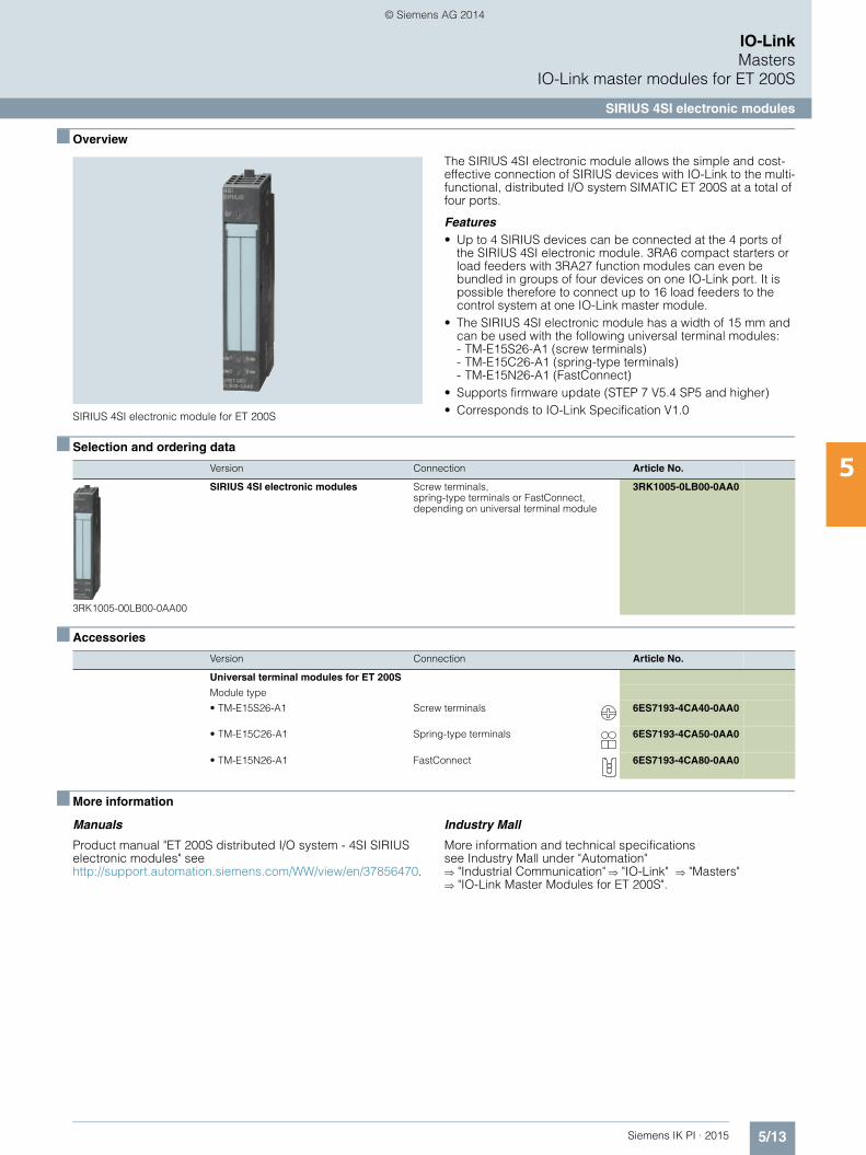
■ Overview
IO-Link 4SI electronic module for ET 200S
The 4SI IO-Link electronic module is an IO-Link master and enables easy integration of sensors and actuators from different manufacturers in the SIMATIC ET 200S multifunctional, distrib-uted I/O system at a total of four ports.
Features• Up to four IO-Link devices (3-wire connection) can be con-
nected to each IO-Link master module. 3RA6 compact start-ers or load feeders with 3RA27 function modules can even be bundled in groups of four devices on one IO-Link port. It is possible therefore to connect up to 16 load feeders to the control system at one IO-Link master module.
• Up to four standard sensors (2-wire/3-wire connection) can be connected.
• The 4SI IO-Link electronic module has a width of 15 mm and can be used with the following universal terminal modules: - TM-E15S26-A1 (screw terminals) - TM-E15C26-A1 (spring-type terminals) - TM-E15N26-A1 (FastConnect)
• Supports firmware update (STEP 7 V5.4 SP4 and higher). • Corresponds to IO-Link Specification V1.0
■ Selection and ordering data
■ Accessories
■ More information
Manuals
Product manual "SIMATIC ET 200S distributed I/O 4SI IO-Link electronic modules" seehttp://support.automation.siemens.com/WW/view/en/29825814
Industry Mall
More information and technical specifications see Industry Mall under "Automation" "Industrial Communication" "IO-Link" "Masters" "IO-Link Master Modules for ET 200S".
Version Connection Article No.
6ES7138-4GA50-0AB0
IO-Link 4SI electronic module Screw terminals, spring-type terminals or FastConnect, depending on universal terminal module
6ES7138-4GA50-0AB0
Version Connection Article No.
Universal terminal modules for ET 200S
Module type
• TM-E15S26-A1 Screw terminals 6ES7193-4CA40-0AA0
• TM-E15C26-A1 Spring-type terminals 6ES7193-4CA50-0AA0
• TM-E15N26-A1 FastConnect 6ES7193-4CA80-0AA0
IKPI_05_en.book Seite 12 Montag, 6. Oktober 2014 4:09 16
© Siemens AG 2014
5/13Siemens IK PI · 2015
IO-LinkMasters
IO-Link master modules for ET 200S
SIRIUS 4SI electronic modules
5
■ Overview
SIRIUS 4SI electronic module for ET 200S
The SIRIUS 4SI electronic module allows the simple and cost-effective connection of SIRIUS devices with IO-Link to the multi-functional, distributed I/O system SIMATIC ET 200S at a total of four ports.
Features• Up to 4 SIRIUS devices can be connected at the 4 ports of
the SIRIUS 4SI electronic module. 3RA6 compact starters or load feeders with 3RA27 function modules can even be bundled in groups of four devices on one IO-Link port. It is possible therefore to connect up to 16 load feeders to the control system at one IO-Link master module.
• The SIRIUS 4SI electronic module has a width of 15 mm and can be used with the following universal terminal modules: - TM-E15S26-A1 (screw terminals) - TM-E15C26-A1 (spring-type terminals) - TM-E15N26-A1 (FastConnect)
• Supports firmware update (STEP 7 V5.4 SP5 and higher) • Corresponds to IO-Link Specification V1.0
■ Selection and ordering data
■ Accessories
■ More information
Manuals
Product manual "ET 200S distributed I/O system - 4SI SIRIUS electronic modules" see http://support.automation.siemens.com/WW/view/en/37856470.
Industry Mall
More information and technical specifications see Industry Mall under "Automation" "Industrial Communication" "IO-Link" "Masters" "IO-Link Master Modules for ET 200S".
Version Connection Article No.
3RK1005-00LB00-0AA00
SIRIUS 4SI electronic modules Screw terminals, spring-type terminals or FastConnect, depending on universal terminal module
3RK1005-0LB00-0AA0
Version Connection Article No.
Universal terminal modules for ET 200S
Module type
• TM-E15S26-A1 Screw terminals 6ES7193-4CA40-0AA0
• TM-E15C26-A1 Spring-type terminals 6ES7193-4CA50-0AA0
• TM-E15N26-A1 FastConnect 6ES7193-4CA80-0AA0
IKPI_05_en.book Seite 13 Montag, 6. Oktober 2014 4:09 16
© Siemens AG 2014
5/14 Siemens IK PI · 2015
IO-LinkMasters
IO-Link master modules for ET 200eco PN
5
■ Overview
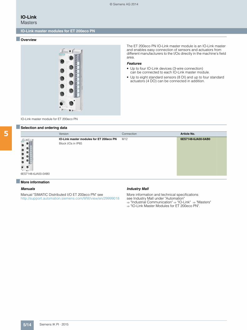
IO-Link master module for ET 200eco PN
The ET 200eco PN IO-Link master module is an IO-Link master and enables easy connection of sensors and actuators from different manufacturers to the I/Os directly in the machine's field area.
Features• Up to four IO-Link devices (3-wire connection)
can be connected to each IO-Link master module.• Up to eight standard sensors (8 DI) and up to four standard
actuators (4 DO) can be connected in addition.
■ Selection and ordering data
■ More information
Manuals
Manual "SIMATIC Distributed I/O ET 200eco PN" see http://support.automation.siemens.com/WW/view/en/29999018
Industry Mall
More information and technical specifications see Industry Mall under "Automation" "Industrial Communication" "IO-Link" "Masters" "IO-Link Master Modules for ET 200eco PN".
Version Connection Article No.
6ES7148-6JA00-0AB0
IO-Link master modules for ET 200eco PN
Block I/Os in IP65
M12 6ES7148-6JA00-0AB0
IKPI_05_en.book Seite 14 Montag, 6. Oktober 2014 4:09 16
© Siemens AG 2014
5/15Siemens IK PI · 2015
IO-LinkInput modules
General data
5
■ Overview
IO-Link input modules
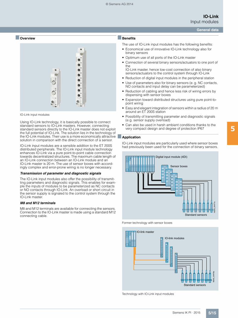
Using IO-Link technology, it is basically possible to connect standard sensors to IO-Link masters. However, connecting standard sensors directly to the IO-Link master does not exploit the full potential of IO-Link. The solution lies in the technology of the IO-Link modules. Their use is a more economically attractive solution in comparison with the direct connection of a sensor.
IO-Link input modules are a sensible addition to the ET 200S distributed peripherals. The IO-Link input module technology enhances IO-Link via a pure point-to-point cable connection towards decentralized structures. The maximum cable length of an IO-Link connection between an IO-Link module and an IO-Link master is 20 m. The use of sensor boxes with accord-ingly complex and error-prone wiring is no longer necessary.
Transmission of parameter and diagnostic signals
The IO-Link input modules also offer the possibility of transmit-ting parameters and diagnostic signals. This enables for exam-ple the inputs of modules to be parameterized as NC contacts or NO contacts through IO-Link. An overload or short circuit in the sensor supply is signaled to the control system through the IO-Link master.
M8 and M12 terminals
M8 and M12 terminals are available for connecting the sensors. Connection to the IO-Link master is made using a standard M12 connecting cable.
■ Benefits
The use of IO-Link input modules has the following benefits:• Economical use of innovative IO-Link technology also for
binary sensors• Optimum use of all ports of the IO-Link master• Connection of several binary sensors/actuators to one port of
the IO-Link master, hence low-cost connection of also binary sensors/actuators to the control system through IO-Link
• Reduction of digital input modules in the peripheral station• Use of parameters also for binary sensors (e. g. NC contacts,
NO contacts and input delay can be parameterized)• Reduction of cabling and hence less risk of wiring errors by
dispensing with sensor boxes• Expansion toward distributed structures using pure point-to-
point wiring• Easy and elegant integration of sensors within a radius of 20 m
around an ET 200S station• Possibility of transmitting parameter and diagnostic signals
(e.g. sensor supply overload)• Can also be used in harsh ambient conditions thanks to the
very compact design and degree of protection IP67
■ Application
IO-Link input modules are particularly used where sensor boxes had previously been used for the connection of binary sensors.
Former technology with sensor boxes
Technology with IO-Link input modules
Sensor boxes
Digital input module (4DI)
Standard sensorsN
SA
0_00
477a
Standard sensors
IO-link master
IO-link modules
NS
A0_
0047
8a
IKPI_05_en.book Seite 15 Montag, 6. Oktober 2014 4:09 16
© Siemens AG 2014
5/16 Siemens IK PI · 2015
IO-LinkInput modules
IO-Link K20 modules
5
■ Selection and ordering data
Type Pin assignment Connection Article No.
3RK5010-0BA10-0AA0
3RK5010-0CA00-0AA0
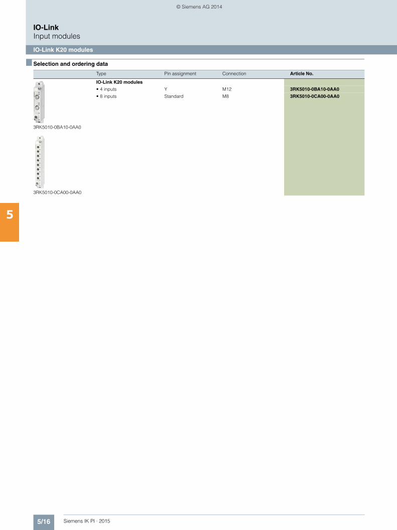
IO-Link K20 modules
• 4 inputs Y M12 3RK5010-0BA10-0AA0
• 8 inputs Standard M8 3RK5010-0CA00-0AA0
IKPI_05_en.book Seite 16 Montag, 6. Oktober 2014 4:09 16
© Siemens AG 2014
5/17Siemens IK PI · 2015
IO-LinkInput modules
IO-Link K20 modules
5
■ Accessories
■ More information
Industry Mall
More information and technical specifications see Industry Mall under "Automation" "Industrial Communication" "IO-Link" "Input Modules" "IO-Link K20 Modules".
Type Article No.
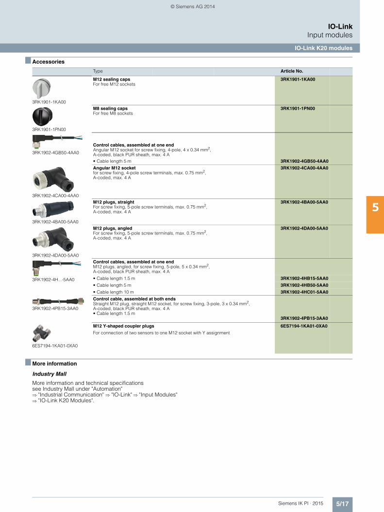
3RK1901-1KA00
M12 sealing capsFor free M12 sockets
3RK1901-1KA00
3RK1901-1PN00
M8 sealing capsFor free M8 sockets
3RK1901-1PN00
3RK1902-4GB50-4AA0
Control cables, assembled at one endAngular M12 socket for screw fixing, 4-pole, 4 x 0.34 mm2, A-coded, black PUR sheath, max. 4 A• Cable length 5 m 3RK1902-4GB50-4AA0
3RK1902-4CA00-4AA0
Angular M12 socket for screw fixing, 4-pole screw terminals, max. 0.75 mm2,A-coded, max. 4 A
3RK1902-4CA00-4AA0
3RK1902-4BA00-5AA0
M12 plugs, straightFor screw fixing, 5-pole screw terminals, max. 0.75 mm2,A-coded, max. 4 A
3RK1902-4BA00-5AA0
3RK1902-4DA00-5AA0
M12 plugs, angled For screw fixing, 5-pole screw terminals, max. 0.75 mm2,A-coded, max. 4 A
3RK1902-4DA00-5AA0
3RK1902-4H...-5AA0
Control cables, assembled at one endM12 plugs, angled, for screw fixing, 5-pole, 5 x 0.34 mm2, A-coded, black PUR sheath, max. 4 A
• Cable length 1.5 m 3RK1902-4HB15-5AA0
• Cable length 5 m 3RK1902-4HB50-5AA0
• Cable length 10 m 3RK1902-4HC01-5AA0
3RK1902-4PB15-3AA0
Control cable, assembled at both endsStraight M12 plug, straight M12 socket, for screw fixing, 3-pole, 3 x 0.34 mm2,A-coded, black PUR sheath, max. 4 A• Cable length 1.5 m
3RK1902-4PB15-3AA0
6ES7194-1KA01-0XA0
M12 Y-shaped coupler plugs
For connection of two sensors to one M12 socket with Y assignment
6ES7194-1KA01-0XA0
IKPI_05_en.book Seite 17 Montag, 6. Oktober 2014 4:09 16
© Siemens AG 2014

5/18 Siemens IK PI · 2015
IO-LinkContactors and contactor assemblies
SIRIUS 3RT20 contactors, 3-pole, 3 ... 18.5 kW
5
■ Overview
Contactors with communication interface, sizes S00 and S0
Contactor versions with communication interface are required to establish a connection to the control system via IO-Link or AS-Interface. The link is established by means of function mod-ules mounted on the front of the contactor.
Contactor size S00 with communication interface and spring-type terminals and contactor size S0 with screw terminals
Standards
IEC 60947-1, EN 60947-1, IEC 60947-4-1, EN 60947-4-1, IEC 60947-5-1, EN 60947-5-1 (auxiliary switches)
The 3RT20 contactors for switching motors are climate-proof and are suitable and tested for use worldwide.
If the devices are used in ambient conditions which deviate from common industrial conditions (IEC 60721-3-3 "Stationary Use, Weather-Protected"), information must be obtained about possi-ble restrictions with regard to the reliability and endurance of the device and possible protective measures. In this case contact our Technical Assistance.
3RT2 contactors are finger-safe according to EN 50274.
The contactors are suitable for screw fixing or for mounting onto TH 35 standard mounting rails according to IEC 60715.
Contact reliability
If voltages 110 V and currents 100 mA are to be switched, the auxiliary contacts of the 3RT2 contactor or 3RH21 contactor relay should be used as they guarantee a high level of contact reliability.
These auxiliary contacts are suitable for solid-state circuits with currents 1 mA at a voltage 17 V.
Connection methods
The 3RT2 contactors are available with screw terminals or spring-type terminals.
Short-circuit protection of the contactors
Short-circuit protection of the contactors without overload relay, see "Technical specifications" (see Note).
To assemble fuseless motor feeders you must select combina-tions of motor starter protector and contactor as explained in "3RA2 Load Feeders".
Motor protection
3RU21 thermal overload relays or 3RB30 solid-state overload relays can be fitted to the 3RT2 contactors for protection against overload. The overload relays must be ordered separately.
Ratings of three-phase motors
The quoted rating (in kW) refers to the output power on the motor shaft (according to the nameplate).
Control supply voltage
Contactors with communication interface are available with 24 V DC operation.
Manuals and configurator
For more information, see • System manual "SIRIUS Innovations – System Overview",
http://support.automation.siemens.com/WW/view/en/60311318 • Manual "SIRIUS Innovations – SIRIUS 3RT2 Contactors/
Contactor Assemblies", http://support.automation.siemens.com/WW/view/en/60306557
For online configurator see www.siemens.com/sirius/configurators.
IKPI_05_en.book Seite 18 Montag, 6. Oktober 2014 4:09 16
© Siemens AG 2014
5/19Siemens IK PI · 2015
IO-LinkContactors and contactor assemblies
SIRIUS 3RT20 contactors, 3-pole, 3 ... 18.5 kW
5
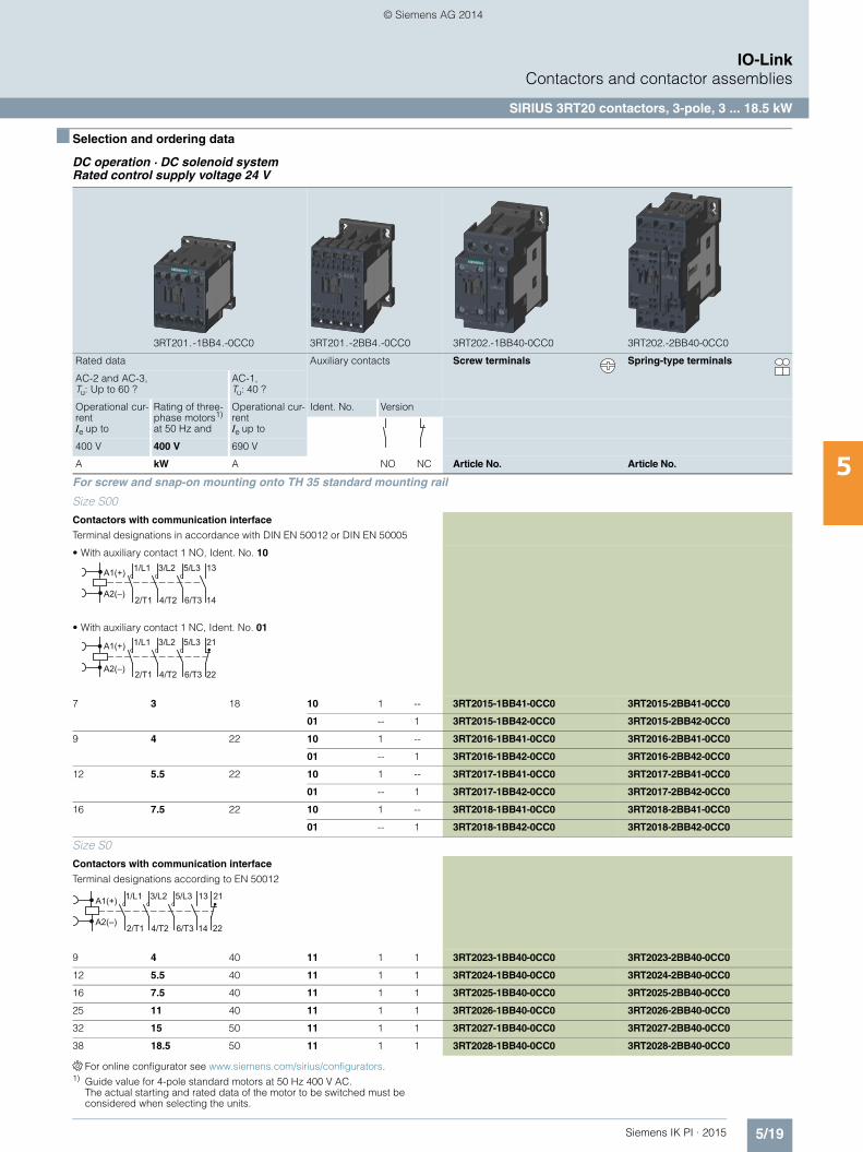
■ Selection and ordering data
DC operation · DC solenoid system Rated control supply voltage 24 V
For online configurator see www.siemens.com/sirius/configurators.1) Guide value for 4-pole standard motors at 50 Hz 400 V AC.
The actual starting and rated data of the motor to be switched must be considered when selecting the units.
3RT201.-1BB4.-0CC0 3RT201.-2BB4.-0CC0 3RT202.-1BB40-0CC0 3RT202.-2BB40-0CC0
Rated data Auxiliary contacts Screw terminals Spring-type terminals
AC-2 and AC-3, Tu: Up to 60 ?
AC-1, Tu: 40 ?
Operational cur-rent Ie up to
Rating of three-phase motors1) at 50 Hz and
Operational cur-rent Ie up to
Ident. No. Version
400 V 400 V 690 V
A kW A NO NC Article No. Article No.
For screw and snap-on mounting onto TH 35 standard mounting rail
Size S00
Contactors with communication interface
Terminal designations in accordance with DIN EN 50012 or DIN EN 50005
• With auxiliary contact 1 NO, Ident. No. 10
• With auxiliary contact 1 NC, Ident. No. 01
7 3 18 10 1 -- 3RT2015-1BB41-0CC0 3RT2015-2BB41-0CC0
01 -- 1 3RT2015-1BB42-0CC0 3RT2015-2BB42-0CC0
9 4 22 10 1 -- 3RT2016-1BB41-0CC0 3RT2016-2BB41-0CC0
01 -- 1 3RT2016-1BB42-0CC0 3RT2016-2BB42-0CC0
12 5.5 22 10 1 -- 3RT2017-1BB41-0CC0 3RT2017-2BB41-0CC0
01 -- 1 3RT2017-1BB42-0CC0 3RT2017-2BB42-0CC0
16 7.5 22 10 1 -- 3RT2018-1BB41-0CC0 3RT2018-2BB41-0CC0
01 -- 1 3RT2018-1BB42-0CC0 3RT2018-2BB42-0CC0
Size S0
Contactors with communication interface
Terminal designations according to EN 50012
9 4 40 11 1 1 3RT2023-1BB40-0CC0 3RT2023-2BB40-0CC0
12 5.5 40 11 1 1 3RT2024-1BB40-0CC0 3RT2024-2BB40-0CC0
16 7.5 40 11 1 1 3RT2025-1BB40-0CC0 3RT2025-2BB40-0CC0
25 11 40 11 1 1 3RT2026-1BB40-0CC0 3RT2026-2BB40-0CC0
32 15 50 11 1 1 3RT2027-1BB40-0CC0 3RT2027-2BB40-0CC0
38 18.5 50 11 1 1 3RT2028-1BB40-0CC0 3RT2028-2BB40-0CC0
6/T3
5/L3
4/T2
3/L2A1(+)
A2(–)2/T1 14
131/L1
6/T3
5/L3
4/T2
3/L2A1(+)
A2(–) 2/T1 22
211/L1
22
21
6/T3
5/L3
4/T2
3/L2A1(+)
A2(–)2/T1 14
131/L1
IKPI_05_en.book Seite 19 Montag, 6. Oktober 2014 4:09 16
© Siemens AG 2014
5/20 Siemens IK PI · 2015
IO-LinkContactors and contactor assemblies
SIRIUS 3RA23 reversing contactor assemblies
5
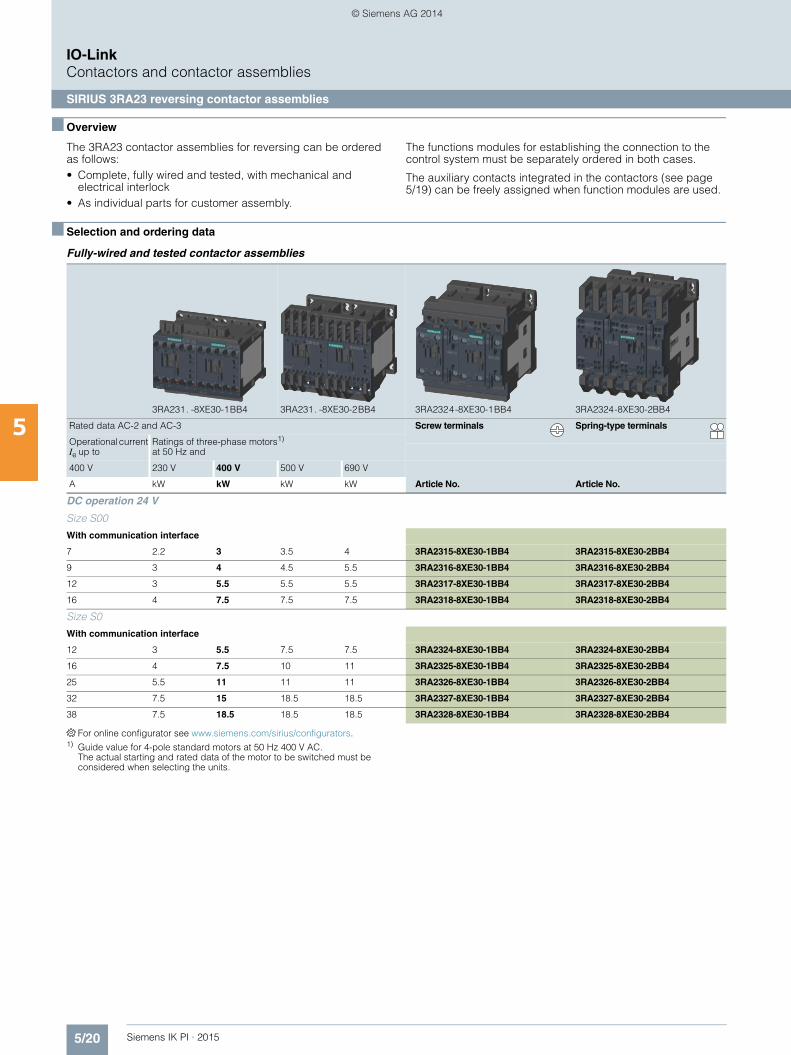
■ Overview
The 3RA23 contactor assemblies for reversing can be ordered as follows:• Complete, fully wired and tested, with mechanical and
electrical interlock• As individual parts for customer assembly.
The functions modules for establishing the connection to the control system must be separately ordered in both cases.
The auxiliary contacts integrated in the contactors (see page 5/19) can be freely assigned when function modules are used.
■ Selection and ordering data
Fully-wired and tested contactor assemblies
For online configurator see www.siemens.com/sirius/configurators.1) Guide value for 4-pole standard motors at 50 Hz 400 V AC.
The actual starting and rated data of the motor to be switched must be considered when selecting the units.
3RA231. -8XE30-1BB4 3RA231. -8XE30-2BB4 3RA2324-8XE30-1BB4 3RA2324-8XE30-2BB4
Rated data AC-2 and AC-3 Screw terminals Spring-type terminals
Operational current Ie up to
Ratings of three-phase motors1) at 50 Hz and
400 V 230 V 400 V 500 V 690 V
A kW kW kW kW Article No. Article No.
DC operation 24 V
Size S00
With communication interface
7 2.2 3 3.5 4 3RA2315-8XE30-1BB4 3RA2315-8XE30-2BB4
9 3 4 4.5 5.5 3RA2316-8XE30-1BB4 3RA2316-8XE30-2BB4
12 3 5.5 5.5 5.5 3RA2317-8XE30-1BB4 3RA2317-8XE30-2BB4
16 4 7.5 7.5 7.5 3RA2318-8XE30-1BB4 3RA2318-8XE30-2BB4
Size S0
With communication interface
12 3 5.5 7.5 7.5 3RA2324-8XE30-1BB4 3RA2324-8XE30-2BB4
16 4 7.5 10 11 3RA2325-8XE30-1BB4 3RA2325-8XE30-2BB4
25 5.5 11 11 11 3RA2326-8XE30-1BB4 3RA2326-8XE30-2BB4
32 7.5 15 18.5 18.5 3RA2327-8XE30-1BB4 3RA2327-8XE30-2BB4
38 7.5 18.5 18.5 18.5 3RA2328-8XE30-1BB4 3RA2328-8XE30-2BB4
IKPI_05_en.book Seite 20 Montag, 6. Oktober 2014 4:09 16
© Siemens AG 2014

5/21Siemens IK PI · 2015
IO-LinkContactors and contactor assemblies
SIRIUS 3RA23 reversing contactor assemblies
5
■ Selection and ordering data (continued)
Components for customer assembly
Assembly kits for all sizes are available for customer assembly of reversing contactor assemblies.
Contactors, overload relays and function modules for reversing starting must be ordered separately.
Selection of contactors for customer assembly
1) Version in size S0 with spring-type terminals: Only the wiring modules for the main circuit are included. No connectors are included for the auxiliary and control circuit.
Rated data AC-2 and AC-3 for 50 Hz 400 V AC
Size Article No.
Rating Operational cur-rent Ie
Contactor Assembly kit Complete assemblies
kW A
3 7 S00 3RT2015-.BB4.-0CC0 3RA2913-2AA. 3RA2315-8XB30-.BB4
4 9 3RT2016-.BB4.-0CC0 3RA2316-8XB30-.BB4
5.5 12 3RT2017-.BB4.-0CC0 3RA2317-8XB30-.BB4
7.5 16 3RT2018-.BB4.-0CC0 3RA2318-8XB30-.BB4
5.5 12 S0 3RT2024-.BB40-0CC0 3RA2923-2AA. 3RA2324-8XB30-.BB4
7.5 16 3RT2025-.BB40-0CC0 3RA2325-8XB30-.BB4
11 25 3RT2026-.BB40-0CC0 3RA2326-8XB30-.BB4
15 32 3RT2027-.BB40-0CC0 3RA2327-8XB30-.BB4
18.5 38 3RT2028-.BB40-0CC0 3RA2328-8XB30-.BB4
3RA2923-2AA1 3RA2923-2AA2
For contactors
Size Version Screw terminals Spring-type terminals
Type Article No. Article No.
Assembly kits for making 3-pole contactor assemblies
3RT201 S00-S00 The assembly kit contains: Mechanical interlock, 2 connecting clips for 2 contactors, wiring modules on the top and bottom
• For main, auxiliary and control circuits 3RA2913-2AA1 3RA2913-2AA2
3RT202 S0-S0 The assembly kit contains: Mechanical interlock, 2 connecting clips for 2 contactors, wiring modules on the top and bottom
• For main, auxiliary and control circuits 3RA2923-2AA1 --
• Only for main circuit1) -- 3RA2923-2AA2
IKPI_05_en.book Seite 21 Montag, 6. Oktober 2014 4:09 16
© Siemens AG 2014
5/22 Siemens IK PI · 2015
IO-LinkContactors and contactor assemblies
SIRIUS 3RA24 contactor assemblies for wye-delta starting
5
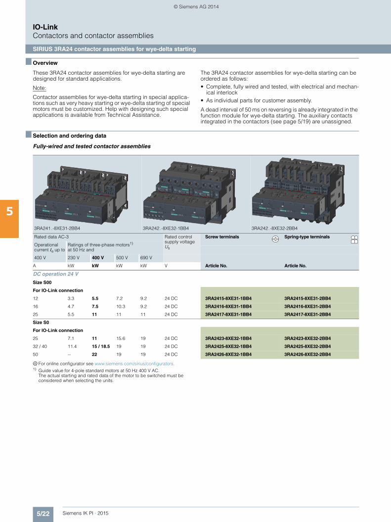
■ Overview
These 3RA24 contactor assemblies for wye-delta starting are designed for standard applications.
Note:
Contactor assemblies for wye-delta starting in special applica-tions such as very heavy starting or wye-delta starting of special motors must be customized. Help with designing such special applications is available from Technical Assistance.
The 3RA24 contactor assemblies for wye-delta starting can be ordered as follows:• Complete, fully wired and tested, with electrical and mechan-
ical interlock• As individual parts for customer assembly.
A dead interval of 50 ms on reversing is already integrated in the function module for wye-delta starting. The auxiliary contacts integrated in the contactors (see page 5/19) are unassigned.
■ Selection and ordering data
Fully-wired and tested contactor assemblies
For online configurator see www.siemens.com/sirius/configurators.1) Guide value for 4-pole standard motors at 50 Hz 400 V AC.
The actual starting and rated data of the motor to be switched must be considered when selecting the units.
3RA241.-8XE31-2BB4 3RA242.-8XE32-1BB4 3RA242.-8XE32-2BB4
Rated data AC-3 Rated control supply voltage Us
Screw terminals Spring-type terminals
Operational current Ie up to
Ratings of three-phase motors1) at 50 Hz and
400 V 230 V 400 V 500 V 690 V
A kW kW kW kW V Article No. Article No.
DC operation 24 V
Size S00
For IO-Link connection
12 3.3 5.5 7.2 9.2 24 DC 3RA2415-8XE31-1BB4 3RA2415-8XE31-2BB4
16 4.7 7.5 10.3 9.2 24 DC 3RA2416-8XE31-1BB4 3RA2416-8XE31-2BB4
25 5.5 11 11 11 24 DC 3RA2417-8XE31-1BB4 3RA2417-8XE31-2BB4
Size S0
For IO-Link connection
25 7.1 11 15.6 19 24 DC 3RA2423-8XE32-1BB4 3RA2423-8XE32-2BB4
32 / 40 11.4 15 / 18.5 19 19 24 DC 3RA2425-8XE32-1BB4 3RA2425-8XE32-2BB4
50 -- 22 19 19 24 DC 3RA2426-8XE32-1BB4 3RA2426-8XE32-2BB4
IKPI_05_en.book Seite 22 Montag, 6. Oktober 2014 4:09 16
© Siemens AG 2014

5/23Siemens IK PI · 2015
IO-LinkContactors and contactor assemblies
SIRIUS 3RA24 contactor assemblies for wye-delta starting
5
■ Selection and ordering data (continued)
Components for customer assembly
Assembly kits with wiring modules and mechanical connectors are available for contactor assemblies for wye-delta starting. Contactors, overload relays, function modules for wye-delta starting, auxiliary switches for electrical interlock – if required also infeed terminals – must be ordered separately.
The wiring kits for sizes S00 and S0 contain the top and bottom main conducting path connections between the line and delta contactors (top) and between the delta and star contactors (bottom).
Selection of contactors for customer assembly
For contactors, see page 5/19.
1) When using the function modules for wye-delta starting, the wiring modules included in the assembly kit for the auxiliary current are not required.
2) Version in size S0 with spring-type terminals: Only the wiring modules for the main circuit are included. No connectors are included for the auxiliary and control circuit.
Rated data AC-3 at 50 Hz 400 V AC Size Article No.
Rating Operational current Ie
Motor current Line/delta contactor Star contactor Complete assemblies
kW A A
5.5 12 9.5 ... 13.8 S00-S00-S00 3RT2015-.BB4.-0CC0 3RT2015-.BB4.-0CC0 3RA2415-8XE31-.BB4
7.5 16 12.1 ... 17 3RT2017-.BB4.-0CC0 3RT2015-.BB4.-0CC0 3RA2416-8XE31-.BB4
11 25 19 ... 25 3RT2018-.BB4.-0CC0 3RT2016-.BB4.-0CC0 3RA2417-8XE31-.BB4
11 25 19 ... 25 S0-S0-S0 3RT2024-.BB40-0CC0 3RT2024-.BB40-0CC0 3RA2423-8XE32-.BB4
15 32 24.1 ... 34 3RT2026-.BB40-0CC0 3RT2024-.BB40-0CC0 3RA2425-8XE32-.BB4
18.5 40 34.5 ... 40 3RT2026-.BB40-0CC0 3RT2024-.BB40-0CC0 3RA2425-8XE32-.BB4
22 50 31 ... 43 3RT2027-.BB40-0CC0 3RT2026-.BB40-0CC0 3RA2426-8XE32-.BB4
3RA2923-2BB1 3RA2923-2BB2
For contactors
Size Version Screw terminals Spring-type terminals
Type Article No. Article No.
Assembly kits for making 3-pole contactor assemblies
3RT201 S00 The assembly kit contains: Mechanical interlock, 4 connecting clips for 3 contactors; star jumper, wiring modules on the top and bottom
• For main, auxiliary and control circuits 3RA2913-2BB1 3RA2913-2BB2
3RT202 S0 The assembly kit contains: Mechanical interlock, 4 connecting clips for 3 contactors, star jumper, wiring modules on the top and bottom1)
• For main, auxiliary and control circuits 3RA2923-2BB1 --
• Only for main circuit2) -- 3RA2923-2BB2
S0 The assembly kit contains: mechanical interlock; 2 connecting clips for 3 contactors, wiring modules on the top and bottom, 3-phase infeed terminals
• For main, auxiliary and control circuits 3RA2924-2BB1 --
IKPI_05_en.book Seite 23 Montag, 6. Oktober 2014 4:09 16
© Siemens AG 2014

5/24 Siemens IK PI · 2015
IO-LinkContactors and contactor assemblies
SIRIUS 3RA27 function module for IO-Link
5
■ Overview
The function modules for mounting onto contactors enable the configuration of starters and contactor assemblies for direct-on-line, reversing and wye-delta starting without any additional, complicated wiring of the individual components.
They include the key control functions required for the particular feeder, e.g. timing and interlocking, and can be connected to the control system via IO-Link.
Manuals
For more information see manual "SIRIUS Function Modules for IO-Link", http://support.automation.siemens.com/WW/view/en/39319600
■ Selection and ordering data
Suitable contactors or reversing contactor assemblies with com-munication interface are required (see pages 5/19 and 5/20).
Note:
When using the function modules, no other auxiliary switches are allowed to be connected to the basic units.
1) For prewired contactor assemblies for reversing starting with commu-nication interface, see page 5/20. When these contactor assemblies are used, the assembly kit for the wiring is already integrated.
2) For complete contactor assemblies for wye-delta starting incl. function modules, see page 5/22.
Version Screw terminals Spring-type terminals
Article No. Article No.
Function modules for direct-on-line starting
3RA2711-1AA00
3RA2711-2AA00
IO-Link connectionIncludes one module connector for assembling an IO-Link group
3RA2711-1AA00 3RA2711-2AA00
Function modules for reversing starting 1)
3RA2711-1BA00
3RA2711-2BA00
IO-Link connection, comprising one basic and one coupling module and an additional module connector for assembling an IO-Link group
3RA2711-1BA00 3RA2711-2BA00
Function modules for wye-delta starting 2)
3RA2711-1CA00
3RA2711-2CA00
IO-Link connection, comprising one basic module and twocoupling modules, plus an additional module con-nector for assembling anIO-Link group
3RA2711-1CA00 3RA2711-2CA00
IKPI_05_en.book Seite 24 Montag, 6. Oktober 2014 4:09 16
© Siemens AG 2014
5/25Siemens IK PI · 2015
IO-LinkContactors and contactor assemblies
SIRIUS 3RA27 function module for IO-Link
5
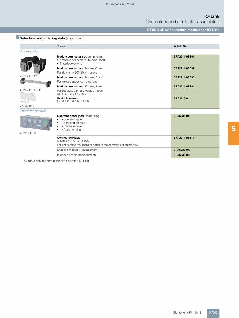
■ Selection and ordering data (continued)
1) Suitable only for communication through IO-Link.
Version Article No.
Accessories
3RA2711-0EE01
3RA2711-0EE02
3RA2910-0
Module connector set, comprising:• 2 module connectors, 14-pole, short• 2 interface covers
3RA2711-0EE01
Module connectors, 14-pole, 8 cm
For size jump S00-S0 + 1 space
3RA2711-0EE02
Module connectors, 14-pole, 21 cm
For various space combinations
3RA2711-0EE03
Module connectors, 10-pole, 8 cm
For separate auxiliary voltage infeed within an IO-Link group
3RA2711-0EE04
Sealable covers for 3RA27, 3RA28, 3RA29
3RA2910-0
Operator panels1)
3RA6935-0A
Operator panel (set), comprising:• 1 x operator panel• 1 x enabling module• 1 x interface cover• 1 x fixing terminal
3RA6935-0A
Connection cable, length 2 m, 10- to 14-pole
For connecting the operator panel to the communication module
3RA2711-0EE11
Enabling modules (replacement) 3RA6936-0A
Interface covers (replacement) 3RA6936-0B
IKPI_05_en.book Seite 25 Montag, 6. Oktober 2014 4:09 16
© Siemens AG 2014
5/26 Siemens IK PI · 2015
IO-LinkSIRIUS 3RB24 solid-state overload relays for IO-Link
3RB24 for IO-Link, up to 630 A for High-Feature applications
5
■ Overview
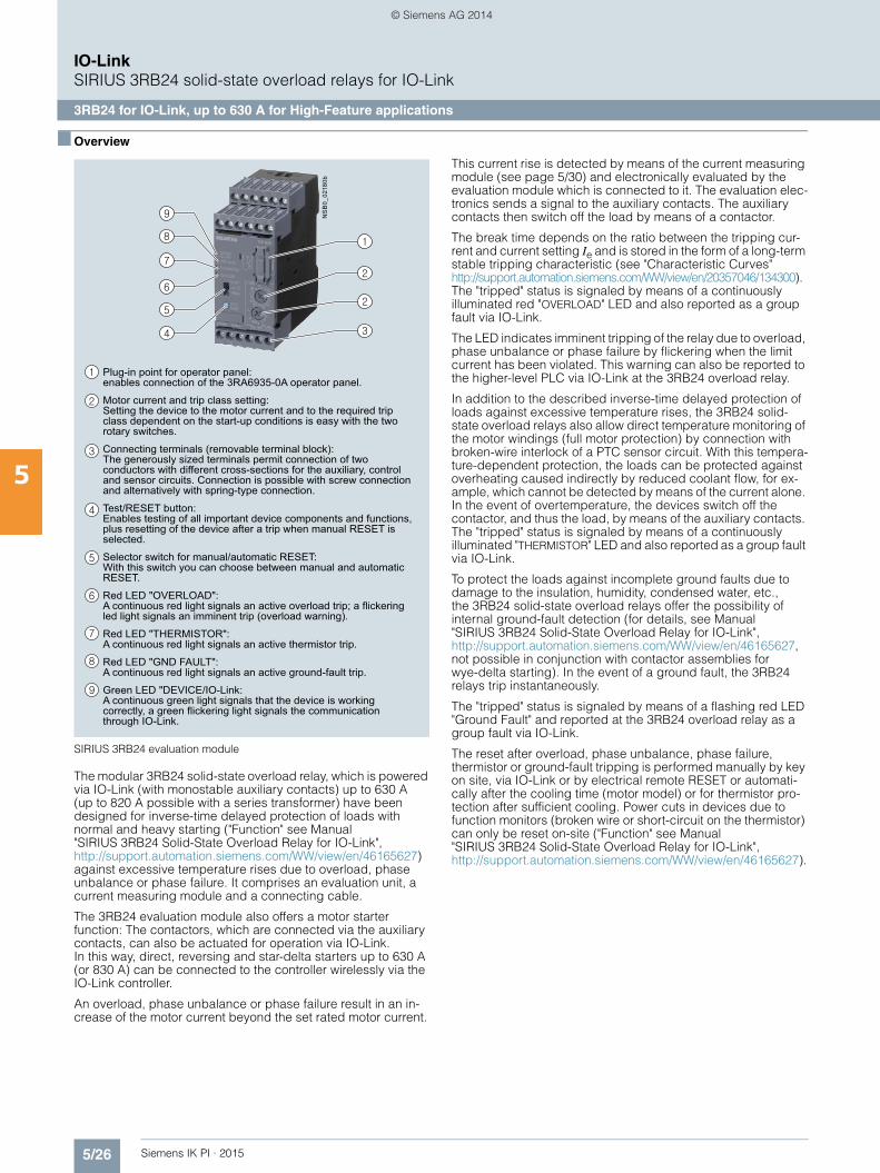
SIRIUS 3RB24 evaluation module
The modular 3RB24 solid-state overload relay, which is powered via IO-Link (with monostable auxiliary contacts) up to 630 A (up to 820 A possible with a series transformer) have been designed for inverse-time delayed protection of loads with normal and heavy starting ("Function" see Manual "SIRIUS 3RB24 Solid-State Overload Relay for IO-Link", http://support.automation.siemens.com/WW/view/en/46165627) against excessive temperature rises due to overload, phase unbalance or phase failure. It comprises an evaluation unit, a current measuring module and a connecting cable.
The 3RB24 evaluation module also offers a motor starter function: The contactors, which are connected via the auxiliary contacts, can also be actuated for operation via IO-Link. In this way, direct, reversing and star-delta starters up to 630 A (or 830 A) can be connected to the controller wirelessly via the IO-Link controller.
An overload, phase unbalance or phase failure result in an in-crease of the motor current beyond the set rated motor current.
This current rise is detected by means of the current measuring module (see page 5/30) and electronically evaluated by the evaluation module which is connected to it. The evaluation elec-tronics sends a signal to the auxiliary contacts. The auxiliary contacts then switch off the load by means of a contactor.
The break time depends on the ratio between the tripping cur-rent and current setting Ie and is stored in the form of a long-term stable tripping characteristic (see "Characteristic Curves" http://support.automation.siemens.com/WW/view/en/20357046/134300). The "tripped" status is signaled by means of a continuously illuminated red "OVERLOAD" LED and also reported as a group fault via IO-Link.
The LED indicates imminent tripping of the relay due to overload, phase unbalance or phase failure by flickering when the limit current has been violated. This warning can also be reported to the higher-level PLC via IO-Link at the 3RB24 overload relay.
In addition to the described inverse-time delayed protection of loads against excessive temperature rises, the 3RB24 solid-state overload relays also allow direct temperature monitoring of the motor windings (full motor protection) by connection with broken-wire interlock of a PTC sensor circuit. With this tempera-ture-dependent protection, the loads can be protected against overheating caused indirectly by reduced coolant flow, for ex-ample, which cannot be detected by means of the current alone. In the event of overtemperature, the devices switch off the contactor, and thus the load, by means of the auxiliary contacts. The "tripped" status is signaled by means of a continuously illuminated "THERMISTOR" LED and also reported as a group fault via IO-Link.
To protect the loads against incomplete ground faults due to damage to the insulation, humidity, condensed water, etc., the 3RB24 solid-state overload relays offer the possibility of internal ground-fault detection (for details, see Manual "SIRIUS 3RB24 Solid-State Overload Relay for IO-Link", http://support.automation.siemens.com/WW/view/en/46165627, not possible in conjunction with contactor assemblies for wye-delta starting). In the event of a ground fault, the 3RB24 relays trip instantaneously.
The "tripped" status is signaled by means of a flashing red LED "Ground Fault" and reported at the 3RB24 overload relay as a group fault via IO-Link.
The reset after overload, phase unbalance, phase failure, thermistor or ground-fault tripping is performed manually by key on site, via IO-Link or by electrical remote RESET or automati-cally after the cooling time (motor model) or for thermistor pro-tection after sufficient cooling. Power cuts in devices due to function monitors (broken wire or short-circuit on the thermistor) can only be reset on-site ("Function" see Manual "SIRIUS 3RB24 Solid-State Overload Relay for IO-Link", http://support.automation.siemens.com/WW/view/en/46165627).
Plug-in point for operator panel: enables connection of the 3RA6935-0A operator panel.
Motor current and trip class setting:Setting the device to the motor current and to the required trip class dependent on the start-up conditions is easy with the two rotary switches.
Connecting terminals (removable terminal block):The generously sized terminals permit connection of two conductors with different cross-sections for the auxiliary, control and sensor circuits. Connection is possible with screw connection and alternatively with spring-type connection.
Test/RESET button:Enables testing of all important device components and functions, plus resetting of the device after a trip when manual RESET is selected.
Selector switch for manual/automatic RESET:With this switch you can choose between manual and automatic RESET.
Red LED "OVERLOAD":A continuous red light signals an active overload trip; a flickering led light signals an imminent trip (overload warning).
Red LED "THERMISTOR":A continuous red light signals an active thermistor trip.
Red LED "GND FAULT":A continuous red light signals an active ground-fault trip.
Green LED "DEVICE/IO-Link:A continuous green light signals that the device is working correctly, a green flickering light signals the communication through IO-Link.
NS
B0_
0218
0b
IKPI_05_en.book Seite 26 Montag, 6. Oktober 2014 4:09 16
© Siemens AG 2014
5/27Siemens IK PI · 2015
IO-LinkSIRIUS 3RB24 solid-state overload relays for IO-Link
3RB24 for IO-Link, up to 630 A for High-Feature applications
5
■ Overview (continued)
In conjunction with a function expansion module, the motor current measured by the microprocessor can be output in the form of an analog signal DC 4 to 20 mA for operating rotary coil instruments or for feeding into analog inputs of programmable logic controllers.
The current values can be transmitted to the higher-level controller via IO-Link.
The 3RB24 solid-state overload relay for IO-Link is suitable for operation with frequency converters. Please follow the instructions in the manual "SIRIUS 3RB24 Solid-State Overload Relay for IO-Link", see http://support.automation.siemens.com/WW/view/en/46165627.
The devices are manufactured in accordance with environmen-tal guidelines and contain environmentally friendly and reusable materials. They comply with all important worldwide standards and approvals.
Type of protection "increased safety EEx e and explosion-proof enclosure EEx d" in accordance with ATEX Directive 94/9/EC
The 3RB24 solid-state overload relay (monostable) are suitable for the overload protection of explosion-proof motors of types of protection EEx e and EEx d.
They comply with the requirements of IEC 60079-7 (Electrical devices for areas subject to explosion hazards - Increased safety "e" as well as for flameproof enclosure "d").
EC type test certificate for Group II, Category (2) G/D has been submitted. On request.
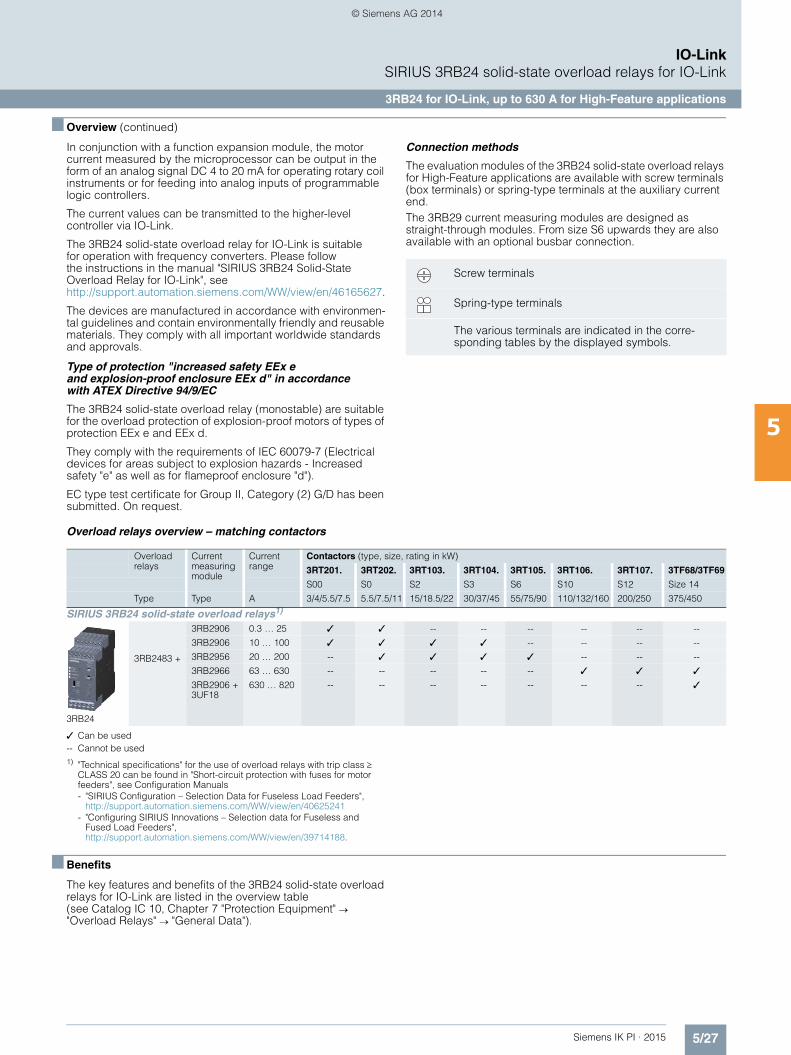
Connection methods
The evaluation modules of the 3RB24 solid-state overload relays for High-Feature applications are available with screw terminals (box terminals) or spring-type terminals at the auxiliary current end. The 3RB29 current measuring modules are designed as straight-through modules. From size S6 upwards they are also available with an optional busbar connection.
Overload relays overview – matching contactors
✓ Can be used-- Cannot be used1) "Technical specifications" for the use of overload relays with trip class
CLASS 20 can be found in "Short-circuit protection with fuses for motor feeders", see Configuration Manuals- "SIRIUS Configuration – Selection Data for Fuseless Load Feeders",
http://support.automation.siemens.com/WW/view/en/40625241- "Configuring SIRIUS Innovations – Selection data for Fuseless and
Fused Load Feeders",http://support.automation.siemens.com/WW/view/en/39714188.
■ Benefits
The key features and benefits of the 3RB24 solid-state overload relays for IO-Link are listed in the overview table (see Catalog IC 10, Chapter 7 "Protection Equipment" "Overload Relays" "General Data").
Screw terminals
Spring-type terminals
The various terminals are indicated in the corre-sponding tables by the displayed symbols.
Overload relays
Current measuring module
Current range
Contactors (type, size, rating in kW)
3RT201. 3RT202. 3RT103. 3RT104. 3RT105. 3RT106. 3RT107. 3TF68/3TF69
S00 S0 S2 S3 S6 S10 S12 Size 14
Type Type A 3/4/5.5/7.5 5.5/7.5/11 15/18.5/22 30/37/45 55/75/90 110/132/160 200/250 375/450
SIRIUS 3RB24 solid-state overload relays1)
3RB24
3RB2483 +
3RB2906 0.3 … 25 ✓ ✓ -- -- -- -- -- --
3RB2906 10 … 100 ✓ ✓ ✓ ✓ -- -- -- --
3RB2956 20 … 200 -- ✓ ✓ ✓ ✓ -- -- --
3RB2966 63 … 630 -- -- -- -- -- ✓ ✓ ✓
3RB2906 + 3UF18
630 … 820 -- -- -- -- -- -- -- ✓
IKPI_05_en.book Seite 27 Montag, 6. Oktober 2014 4:09 16
© Siemens AG 2014
5/28 Siemens IK PI · 2015
IO-LinkSIRIUS 3RB24 solid-state overload relays for IO-Link
3RB24 for IO-Link, up to 630 A for High-Feature applications
5
■ Application
Industries
The 3RB24 solid-state overload relays are suitable for customers from all industries who want to guarantee optimum inverse-time delayed and temperature-dependent protection of their electri-cal loads (e.g. motors) under normal and heavy starting condi-tions (CLASS 5 to 30), minimize project completion times, inven-tories and energy consumption, and optimize plant availability and maintenance management.
Application area
The 3RB24 solid-state overload relays have been designed for the protection of three-phase asynchronous and single-phase AC motors.
In addition to protection function, these devices can be used together with contactors as direct or reversing starters (star-delta (wye-delta) start also possible), which are controlled via IO-Link. This makes it possible to directly control drives via IO-Link from a higher-level controller or on site via the optional hand-held device lamps and also, for example, to return current values directly via IO-Link.
If single-phase AC motors are to be protected by the 3RB24 solid-state overload relays, the main current paths of the current measuring modules must be series-connected ("Circuit Dia-grams" see Manual "SIRIUS 3RB24 Solid-State Overload Relay for IO-Link", http://support.automation.siemens.com/WW/view/en/46165627).
Ambient conditions
The devices are insensitive to external influences such as shocks, corrosive ambient conditions, ageing and temperature fluctuations.
For the temperature range from –25 C to +60 °C, the 3RB24 solid-state overload relays compensate the temperature in ac-cordance with IEC 60947-4-1.
Configuration notes for use of the devices below –25 °C or above +60 °C on request.
IKPI_05_en.book Seite 28 Montag, 6. Oktober 2014 4:09 16
© Siemens AG 2014
5/29Siemens IK PI · 2015
IO-LinkSIRIUS 3RB24 solid-state overload relays for IO-Link
3RB24 for IO-Link, up to 630 A for High-Feature applications
5
■ Selection and ordering data
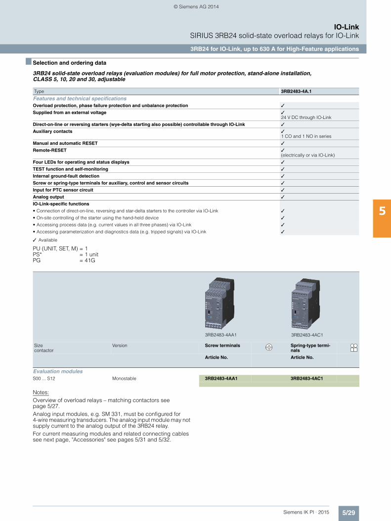
3RB24 solid-state overload relays (evaluation modules) for full motor protection, stand-alone installation, CLASS 5, 10, 20 and 30, adjustable
✓ Available
PU (UNIT, SET, M) = 1PS* = 1 unitPG = 41G
Notes:Overview of overload relays – matching contactors see page 5/27.Analog input modules, e.g. SM 331, must be configured for 4-wire measuring transducers. The analog input module may not supply current to the analog output of the 3RB24 relay.For current measuring modules and related connecting cables see next page, "Accessories" see pages 5/31 and 5/32.
Type 3RB2483-4A.1
Features and technical specificationsOverload protection, phase failure protection and unbalance protection ✓
Supplied from an external voltage ✓24 V DC through IO-Link
Direct-on-line or reversing starters (wye-delta starting also possible) controllable through IO-Link ✓
Auxiliary contacts ✓1 CO and 1 NO in series
Manual and automatic RESET ✓
Remote-RESET ✓(electrically or via IO-Link)
Four LEDs for operating and status displays ✓
TEST function and self-monitoring ✓
Internal ground-fault detection ✓
Screw or spring-type terminals for auxiliary, control and sensor circuits ✓
Input for PTC sensor circuit ✓
Analog output ✓
IO-Link-specific functions
• Connection of direct-on-line, reversing and star-delta starters to the controller via IO-Link ✓
• On-site controlling of the starter using the hand-held device ✓
• Accessing process data (e.g. current values in all three phases) via IO-Link ✓
• Accessing parameterization and diagnostics data (e.g. tripped signals) via IO-Link ✓
Size contactor
Version Screw terminals Spring-type termi-nals
Article No. Article No.
Evaluation modules S00 ... S12 Monostable 3RB2483-4AA1 3RB2483-4AC1
3RB2483-4AC13RB2483-4AA1
IKPI_05_en.book Seite 29 Montag, 6. Oktober 2014 4:09 16
© Siemens AG 2014
5/30 Siemens IK PI · 2015
IO-LinkSIRIUS 3RB24 solid-state overload relays for IO-Link
Current measuring modules
5
■ Overview
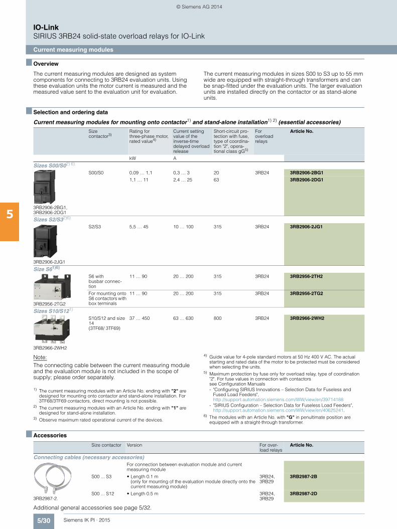
The current measuring modules are designed as system components for connecting to 3RB24 evaluation units. Using these evaluation units the motor current is measured and the measured value sent to the evaluation unit for evaluation.
The current measuring modules in sizes S00 to S3 up to 55 mm wide are equipped with straight-through transformers and can be snap-fitted under the evaluation units. The larger evaluation units are installed directly on the contactor or as stand-alone units.
■ Selection and ordering data
Current measuring modules for mounting onto contactor1) and stand-alone installation1) 2) (essential accessories)
Note:The connecting cable between the current measuring module and the evaluation module is not included in the scope of supply; please order separately.
1) The current measuring modules with an Article No. ending with "2" are designed for mounting onto contactor and stand-alone installation. For 3TF68/3TF69 contactors, direct mounting is not possible.
2) The current measuring modules with an Article No. ending with "1" are designed for stand-alone installation.
3) Observe maximum rated operational current of the devices.
4) Guide value for 4-pole standard motors at 50 Hz 400 V AC. The actual starting and rated data of the motor to be protected must be considered when selecting the units.
5) Maximum protection by fuse only for overload relay, type of coordination "2". For fuse values in connection with contactors see Configuration Manuals- "Configuring SIRIUS Innovations – Selection Data for Fuseless and
Fused Load Feeders", http://support.automation.siemens.com/WW/view/en/39714188
- "SIRIUS Configuration – Selection Data for Fuseless Load Feeders", http://support.automation.siemens.com/WW/view/en/40625241.
6) The modules with an Article No. with "G" in penultimate position are equipped with a straight-through transformer.
■ Accessories
Additional general accessories see page 5/32.
Size contactor3)
Rating for three-phase motor, rated value4)
Current setting value of the inverse-time delayed overload release
Short-circuit pro-tection with fuse, type of coordina-tion "2", opera-tional class gG5)
For overload relays
Article No.
kW A
Sizes S00/S02) 6)
S00/S0 0,09 … 1,1 0,3 … 3 20 3RB24 3RB2906-2BG1
1,1 … 11 2,4 … 25 63 3RB2906-2DG1
Sizes S2/S32)6)
S2/S3 5,5 … 45 10 … 100 315 3RB24 3RB2906-2JG1
Size S61)6)
S6 with busbar connec-tion
11 … 90 20 … 200 315 3RB24 3RB2956-2TH2
For mounting onto S6 contactors with box terminals
11 … 90 20 … 200 315 3RB24 3RB2956-2TG2
Sizes S10/S121)
S10/S12 and size 14 (3TF68/ 3TF69)
37 … 450 63 … 630 800 3RB24 3RB2966-2WH2
3RB2906-2BG1, 3RB2906-2DG1
3RB2906-2JG1
3RB2956-2TG2
3RB2966-2WH2
Size contactor Version For over-load relays
Article No.
Connecting cables (necessary accessories)
3RB2987-2.
For connection between evaluation module and current measuring module
S00 ... S3 • Length 0.1 m (only for mounting of the evaluation module directly onto the current measuring module)
3RB24, 3RB29
3RB2987-2B
S00 ... S12 • Length 0.5 m 3RB24, 3RB29
3RB2987-2D
IKPI_05_en.book Seite 30 Montag, 6. Oktober 2014 4:09 16
© Siemens AG 2014
5/31Siemens IK PI · 2015
IO-LinkSIRIUS 3RB24 solid-state overload relays for IO-Link
Accessories
5
■ Overview
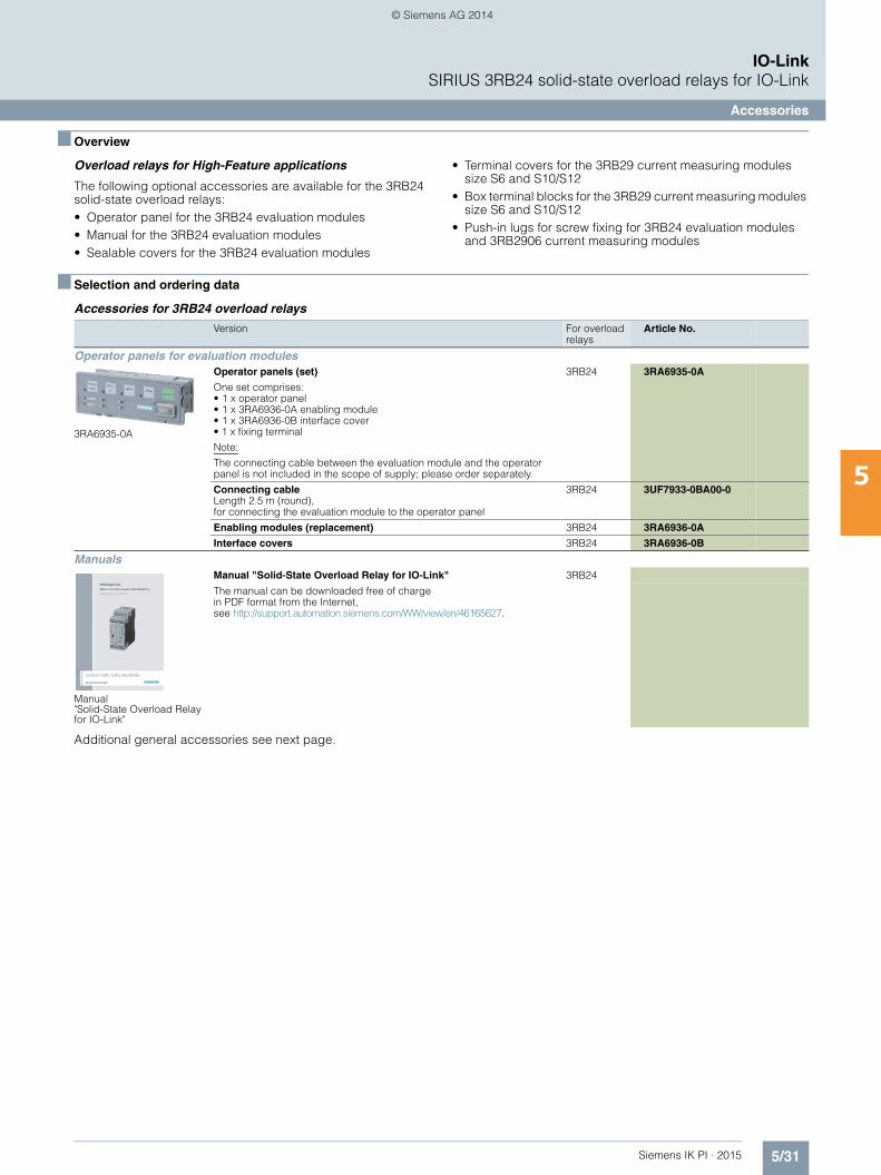
Overload relays for High-Feature applications
The following optional accessories are available for the 3RB24 solid-state overload relays:• Operator panel for the 3RB24 evaluation modules• Manual for the 3RB24 evaluation modules• Sealable covers for the 3RB24 evaluation modules
• Terminal covers for the 3RB29 current measuring modules size S6 and S10/S12
• Box terminal blocks for the 3RB29 current measuring modules size S6 and S10/S12
• Push-in lugs for screw fixing for 3RB24 evaluation modules and 3RB2906 current measuring modules
■ Selection and ordering data
Accessories for 3RB24 overload relays
Additional general accessories see next page.
Version For overload relays
Article No.
Operator panels for evaluation modules
3RA6935-0A
Operator panels (set)
One set comprises:• 1 x operator panel• 1 x 3RA6936-0A enabling module• 1 x 3RA6936-0B interface cover• 1 x fixing terminal
Note:
The connecting cable between the evaluation module and the operator panel is not included in the scope of supply; please order separately.
3RB24 3RA6935-0A
Connecting cable Length 2.5 m (round), for connecting the evaluation module to the operator panel
3RB24 3UF7933-0BA00-0
Enabling modules (replacement) 3RB24 3RA6936-0A
Interface covers 3RB24 3RA6936-0B
Manuals
Manual "Solid-State Overload Relay for IO-Link"
Manual "Solid-State Overload Relay for IO-Link" 3RB24
The manual can be downloaded free of charge in PDF format from the Internet, see http://support.automation.siemens.com/WW/view/en/46165627.
IKPI_05_en.book Seite 31 Montag, 6. Oktober 2014 4:09 16
© Siemens AG 2014
5/32 Siemens IK PI · 2015
IO-LinkSIRIUS 3RB24 solid-state overload relays for IO-Link
Accessories
5
■ Selection and ordering data (continued)
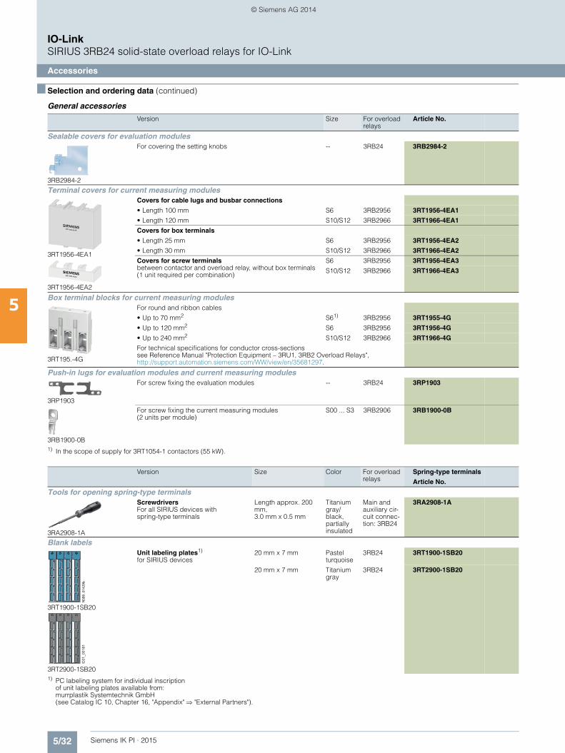
General accessories
1) In the scope of supply for 3RT1054-1 contactors (55 kW).
1) PC labeling system for individual inscriptionof unit labeling plates available from:murrplastik Systemtechnik GmbH(see Catalog IC 10, Chapter 16, "Appendix" "External Partners").
Version Size For overload relays
Article No.
Sealable covers for evaluation modules
3RB2984-2
For covering the setting knobs -- 3RB24 3RB2984-2
Terminal covers for current measuring modules
3RT1956-4EA1
3RT1956-4EA2
Covers for cable lugs and busbar connections
• Length 100 mm S6 3RB2956 3RT1956-4EA1
• Length 120 mm S10/S12 3RB2966 3RT1966-4EA1
Covers for box terminals
• Length 25 mm S6 3RB2956 3RT1956-4EA2
• Length 30 mm S10/S12 3RB2966 3RT1966-4EA2
Covers for screw terminals between contactor and overload relay, without box terminals (1 unit required per combination)
S6 3RB2956 3RT1956-4EA3
S10/S12 3RB2966 3RT1966-4EA3
Box terminal blocks for current measuring modules
3RT195.-4G
For round and ribbon cables
• Up to 70 mm2 S61) 3RB2956 3RT1955-4G
• Up to 120 mm2 S6 3RB2956 3RT1956-4G
• Up to 240 mm2 S10/S12 3RB2966 3RT1966-4G
For technical specifications for conductor cross-sections see Reference Manual "Protection Equipment – 3RU1, 3RB2 Overload Relays", http://support.automation.siemens.com/WW/view/en/35681297.
Push-in lugs for evaluation modules and current measuring modules
3RP1903
For screw fixing the evaluation modules -- 3RB24 3RP1903
3RB1900-0B
For screw fixing the current measuring modules(2 units per module)
S00 ... S3 3RB2906 3RB1900-0B
Version Size Color For overload relays
Spring-type terminals
Article No.
Tools for opening spring-type terminals
3RA2908-1A
Screwdrivers For all SIRIUS devices with spring-type terminals
Length approx. 200 mm, 3.0 mm x 0.5 mm
Titanium gray/black, partially insulated
Main and auxiliary cir-cuit connec-tion: 3RB24
3RA2908-1A
Blank labels
3RT1900-1SB20
3RT2900-1SB20
Unit labeling plates1)
for SIRIUS devices20 mm x 7 mm Pastel
turquoise3RB24 3RT1900-1SB20
20 mm x 7 mm Titanium gray
3RB24 3RT2900-1SB20
NSB
0_01
429b
IC01
_001
81
IKPI_05_en.book Seite 32 Montag, 6. Oktober 2014 4:09 16
© Siemens AG 2014

5/33Siemens IK PI · 2015
IO-LinkSIRIUS 3RA6 compact starters
SIRIUS 3RA64, 3RA65 compact starters for IO-Link
5
■ Overview
Communications integration using IO-Link
The 3RA64/65 compact starters comply with IO-Link specifica-tion V1.0. Up to 4 compact starters in IO-Link version (reversing and direct-on-line starters) can be connected together and easily linked to the IO-Link master through a standardized IO-Link connection. The 4SI SIRIUS electronic module can be used, for example, as an IO-Link master for the connection to the SIMATIC ET 200S distributed I/O system.
The IO-Link connection enables a high density of information in the local range.
The diagnostics data of the process collected by the 3RA6 com-pact starter, e.g. short circuit, end of service life, limit position etc., are not only indicated on the compact starter itself but also transmitted to the higher-level control system through IO-Link.
Thanks to the optionally available operator panel, which can be installed in the control cabinet door, it is easy to control the 3RA6 compact starter with IO-Link from the control cabinet door.
Note
For general data about 3RA6 compact starters, see Chapter 4 "AS-Interface" "3RA6 Compact Starters" "General Data"
■ Selection and ordering data
3RA64 direct-on-line starters
1) The actual starting and rated data of the motor to be protected must be considered when selecting the units.
3RA64 with 3RA6911-1A auxiliary switch block
Direct-on-line start Rated control supply voltage 24 V DC
Width 45 mm
Rated short-circuit current ICS = 53 kA at 400 V
A set of 3A6940-0A adapters is required for screw fixing.
Standard three-phase motor 4-pole at 400 V AC1)
Standard output P
Setting range for solid-state overload release
Instantaneous overcurrent release
Screw terminals Spring-type terminals
kW A A Article No. Article No.
For standard mounting rail or screw fixing,including 1 pair of main circuit terminals and 1 pair of control circuit terminals
0.09 0.1 ... 0.4 56 3RA6400-1AB42 3RA6400-2AB42
0.37 0.32 ... 1.25 56 3RA6400-1BB42 3RA6400-2BB42
1.5 1 ... 4 56 3RA6400-1CB42 3RA6400-2CB42
5.5 3 ... 12 168 3RA6400-1DB42 3RA6400-2DB42
15 8 ... 32 448 3RA6400-1EB42 3RA6400-2EB42
For use in the infeed system for 3RA6,without main circuit terminals with 1 pair of control circuit terminals
0.09 0.1 ... 0.4 56 3RA6400-1AB43 3RA6400-2AB43
0.37 0.32 ... 1.25 56 3RA6400-1BB43 3RA6400-2BB43
1.5 1 ... 4 56 3RA6400-1CB43 3RA6400-2CB43
5.5 3 ... 12 168 3RA6400-1DB43 3RA6400-2DB43
15 8 ... 32 448 3RA6400-1EB43 3RA6400-2EB43
NSB0_01946
IKPI_05_en.book Seite 33 Montag, 6. Oktober 2014 4:09 16
© Siemens AG 2014
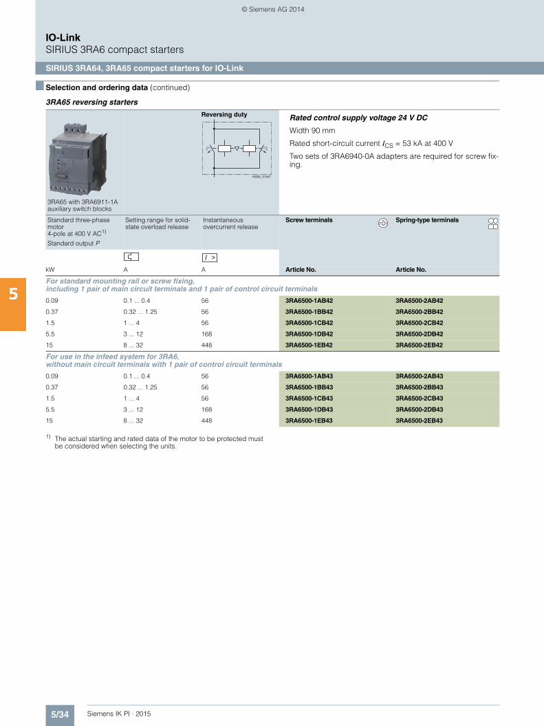
5/34 Siemens IK PI · 2015
IO-LinkSIRIUS 3RA6 compact starters
SIRIUS 3RA64, 3RA65 compact starters for IO-Link
5
■ Selection and ordering data (continued)
3RA65 reversing starters
1) The actual starting and rated data of the motor to be protected must be considered when selecting the units.
3RA65 with 3RA6911-1A auxiliary switch blocks
Reversing duty Rated control supply voltage 24 V DC
Width 90 mm
Rated short-circuit current ICS = 53 kA at 400 V
Two sets of 3RA6940-0A adapters are required for screw fix-ing.
Standard three-phase motor 4-pole at 400 V AC1)
Standard output P
Setting range for solid-state overload release
Instantaneous overcurrent release
Screw terminals Spring-type terminals
kW A A Article No. Article No.
For standard mounting rail or screw fixing,including 1 pair of main circuit terminals and 1 pair of control circuit terminals
0.09 0.1 ... 0.4 56 3RA6500-1AB42 3RA6500-2AB42
0.37 0.32 ... 1.25 56 3RA6500-1BB42 3RA6500-2BB42
1.5 1 ... 4 56 3RA6500-1CB42 3RA6500-2CB42
5.5 3 ... 12 168 3RA6500-1DB42 3RA6500-2DB42
15 8 ... 32 448 3RA6500-1EB42 3RA6500-2EB42
For use in the infeed system for 3RA6,without main circuit terminals with 1 pair of control circuit terminals
0.09 0.1 ... 0.4 56 3RA6500-1AB43 3RA6500-2AB43
0.37 0.32 ... 1.25 56 3RA6500-1BB43 3RA6500-2BB43
1.5 1 ... 4 56 3RA6500-1CB43 3RA6500-2CB43
5.5 3 ... 12 168 3RA6500-1DB43 3RA6500-2DB43
15 8 ... 32 448 3RA6500-1EB43 3RA6500-2EB43
NSB0_01947
IKPI_05_en.book Seite 34 Montag, 6. Oktober 2014 4:09 16
© Siemens AG 2014
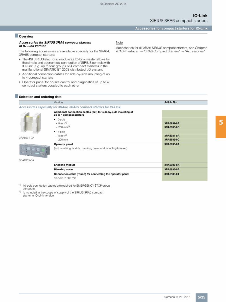
5/35Siemens IK PI · 2015
IO-LinkSIRIUS 3RA6 compact starters
Accessories for compact starters for IO-Link
5
■ Overview
Accessories for SIRIUS 3RA6 compact starters in IO-Link version
The following accessories are available specially for the 3RA64, 3RA65 compact starters:• The 4SI SIRIUS electronic module as IO-Link master allows for
the simple and economical connection of SIRIUS controls with IO-Link (e.g. up to four groups of 4 compact starters) to the multifunctional SIMATIC ET 200S distributed I/O system.
• Additional connection cables for side-by-side mounting of up to 4 compact starters
• Operator panel for on-site control and diagnostics of up to 4 compact starters coupled to each other
Note
Accessories for all 3RA6 SIRIUS compact starters, see Chapter 4 "AS-Interface" "3RA6 Compact Starters" "Accessories"
■ Selection and ordering data
1) 10-pole connection cables are required for EMERGENCY-STOP group concepts.
2) Is included in the scope of supply of the SIRIUS 3RA6 compact starter in IO-Link version.
Version Article No.
Accessories especially for 3RA64, 3RA65 compact starters for IO-Link
3RA6931-0A
Additional connection cables (flat) for side-by-side mounting of up to 4 compact starters
• 10-pole- 8 mm1) 3RA6932-0A- 200 mm1) 3RA6933-0B
• 14-pole- 8 mm2) 3RA6931-0A- 200 mm 3RA6933-0C
3RA6935-0A
Operator panel
(incl. enabling module, blanking cover and mounting bracket)
3RA6935-0A
Enabling module 3RA6936-0A
Blanking cover 3RA6936-0B
Connection cable (round) for connecting the operator panel
10-pole, 2 000 mm
3RA6933-0A
IKPI_05_en.book Seite 35 Montag, 6. Oktober 2014 4:09 16
© Siemens AG 2014
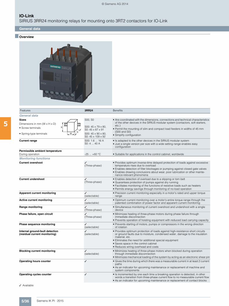
5/36 Siemens IK PI · 2015
IO-LinkSIRIUS 3RR24 monitoring relays for mounting onto 3RT2 contactors for IO-Link
General data
5
■ Overview
✓ Available
Features 3RR24 Benefits
General dataSizes
Dimensions in mm (W x H x D)
• Screw terminals
• Spring-type terminals
S00, S0
S00: 45 x 79 x 80,S0: 45 x 87 x 91
S00: 45 x 90 x 80,S0: 45 x 109 x 92
• Are coordinated with the dimensions, connections and technical characteristics of the other devices in the SIRIUS modular system (contactors, soft starters, etc.)
• Permit the mounting of slim and compact load feeders in widths of 45 mm(S00 and S0)
• Simplify configuration
Current range S00: 1.6 ... 16 AS0: 4 ... 40 A
• Is adapted to the other devices in the SIRIUS modular system• Just a single version per size with a wide setting range enables easy
configuration
Permissible ambient temperature During operation -25 ... +60 °C • Suitable for applications in the control cabinet, worldwide
Monitoring functionsCurrent overshoot ✓
(Three-phase)• Provides optimum inverse-time delayed protection of loads against excessive
temperature rises due to overload• Enables detection of filter blockages or pumping against closed gate valves• Enables drawing conclusions about wear, poor lubrication or other mainte-
nance-relevant phenomena
Current undershoot ✓(Three-phase)
• Enables detection of overload due to a slipping or torn belt • Guarantees protection of pumps against dry running• Facilitates monitoring of the functions of resistive loads such as heaters• Permits energy savings through monitoring of no-load operation
Apparent current monitoring ✓(selectable)
• Precision current monitoring especially in a motor's rated and upper torque range
Active current monitoring ✓(selectable)
• Optimum current monitoring over a motor's entire torque range through the patented combination of power factor and apparent current monitoring
Range monitoring ✓(Three-phase)
• Simultaneous monitoring of current overshoot and undershoot with a single device
Phase failure, open circuit ✓(Three-phase)
• Minimizes heating of three-phase motors during phase failure through immediate disconnection
• Prevents operation of hoisting equipment with reduced load carrying capacity
Phase sequence monitoring ✓(selectable)
• Prevents starting of motors, pumps or compressors in the wrong direction of rotation
Internal ground-fault detection(residual current monitoring)
✓(selectable)
• Provides optimum protection of loads against high-resistance short circuits or ground faults due to moisture, condensed water, damage to the insulation material, etc.
• Eliminates the need for additional special equipment• Saves space in the control cabinet• Reduces wiring overhead and costs
Blocking current monitoring ✓(selectable)
• Minimizes heating of three-phase motors when blocked during operation through immediate disconnection
• Minimizes mechanical loading of the system by acting as an electronic shear pin
Operating hours counter ✓ • Gives the time during which there was a measurable current in at least 2 current paths
• As an indicator for upcoming maintenance or replacement of machine and system components
Operating cycles counter ✓ • Is incremented by one each time a breaking operation is detected, in other words a transition from three-phase current flow to no measurable current flow
• As an indicator for upcoming maintenance or replacement of contact blocks
W
H
D
IKPI_05_en.book Seite 36 Montag, 6. Oktober 2014 4:09 16
© Siemens AG 2014
5/37Siemens IK PI · 2015
IO-LinkSIRIUS 3RR24 monitoring relays for mounting onto 3RT2 contactors for IO-Link
General data
5
■ Overview (continued)
✓ Available
Features 3RR24 Benefits
FeaturesRESET function ✓ • Allows manual or automatic resetting of the relay
• Resetting directly on the device, by switching the control supply voltage off and on or via IO-Link (remote RESET)
ON-delay time 0 ... 999.9 s • Enables motor starting without evaluation of the starting current• Can be used for monitoring motors with lengthy start-up
Tripping delay time 0 ... 999.9 s • Permits brief threshold value violations during operation• Prevents frequent warnings and disconnections with currents near the
threshold values
Operating and indicating ele-ments
Displays and buttons • For setting the threshold values and delay times• For selectable functions• For quick and selective diagnostics• Displays for permanent display of measured values
Integrated contacts 1 CO contact, 1 semiconductor output (in SIO mode)
• Enable disconnection of the system or process when there is an irregularity• Can be used to output signals
Design of load feedersShort-circuit strength up to 100 kA at 690 V(in conjunction with the corresponding fuses or the corresponding motor starter protector)
✓ • Provides optimum protection of the loads and operating personnel in the event of short circuits due to insulation faults or faulty switching operations
Electrical and mechanical matching to 3RT2 contactors
✓ • Simplifies configuration• Reduces wiring outlay and costs• Enables stand-alone installation as well as space-saving direct mounting
Spring-type terminals for main circuit and auxiliary circuits
✓(optional)
• Enables fast connections• Permits vibration-resistant connections• Enables maintenance-free connections
Other features
Suitable for single- and three-phase loads ✓ • Enables the monitoring of single-phase systems through parallel infeed at the contactor or looping the current through the three phase connections
Wide setting ranges ✓ • Reduce the number of variants• Minimize the configuration outlay and costs• Minimize storage overheads, storage costs, tied-up capital
Power supply 24 V DC • Direct via IO-Link master or via an external auxiliary voltage independent of the IO-Link
• Minimizes the configuring overhead and costs
IKPI_05_en.book Seite 37 Montag, 6. Oktober 2014 4:09 16
© Siemens AG 2014
5/38 Siemens IK PI · 2015
IO-LinkSIRIUS 3RR24 monitoring relays for mounting onto 3RT2 contactors for IO-Link
General data
5
■ Overview (continued)
Possible combinations of 3RR24 monitoring relays with 3RT2 contactors for IO-Link
✓ Available
Notes:
Devices required for the communication via IO-Link:• Any controller that supports the IO-Link
(e.g. ET 200S with CPU or S7-1200), see Catalog ST 70 "Products for Totally Integrated Automation"
• IO-Link master (e.g. 4SI or 4SI IO-Link electronic module for SIMATIC ET200S or SM 1278 for S7-1200) see Catalog ST 70 "Products for Totally Integrated Automation"
Each monitoring relay requires an IO-Link channel.
Connection methods
Selection tables for the 3RR24 monitoring relays can be found on the following pages.
■ More information
Configuration Manual "Configuring SIRIUS Innovations – Selection Data for Fuseless and Fused Load Feeders" see http://support.automation.siemens.com/WW/view/en/39714188.
System Manual "Industrial Controls – SIRIUS Innovations" see http://support.automation.siemens.com/WW/view/en/60311318.
Manual "3UG48/3RR24 Monitoring Relays for IO-Link" see http://support.automation.siemens.com/WW/view/en/54375430.
Notes on safety:
System networking requires suitable protective measures (in-cluding network segmentation for IT security) in order to ensure safe plant operation, see www.siemens.com/industrialsecurity.
More information about the subject of Industrial Security see www.siemens.com/industrialsecurity.
Monitoring relays Current range Contactors (type, size, rating)
3RT201 3RT202
S00 S0
Type A 3/4/5.5/7.5 kW 5.5/7.5/11/15/18.5 kW
3RR2441 1.6 ... 16 ✓ With stand-alone installation support
3RR2442 4 ... 40 With stand-alone installation support ✓
Screw terminals
Spring-type terminals
IKPI_05_en.book Seite 38 Montag, 6. Oktober 2014 4:09 16
© Siemens AG 2014
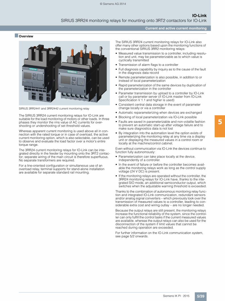
5/39Siemens IK PI · 2015
IO-LinkSIRIUS 3RR24 monitoring relays for mounting onto 3RT2 contactors for IO-Link
Current and active current monitoring
5
■ Overview
SIRIUS 3RR2441 and 3RR2442 current monitoring relay
The SIRIUS 3RR24 current monitoring relays for IO-Link are suitable for the load monitoring of motors or other loads. In three phases they monitor the rms value of AC currents for over-shooting or undershooting of set threshold values.
Whereas apparent current monitoring is used above all in con-nection with the rated torque or in case of overload, the active current monitoring option, which is also selectable, can be used to observe and evaluate the load factor over a motor's entire torque range.
The 3RR24 current monitoring relays for IO-Link can be inte-grated directly in the feeder by mounting onto the 3RT2 contac-tor; separate wiring of the main circuit is therefore superfluous. No separate transformers are required.
For a line-oriented configuration or simultaneous use of an overload relay, terminal supports for stand-alone installation are available for separate standard rail mounting.
The SIRIUS 3RR24 current monitoring relays for IO-Link also offer many other options based upon the monitoring functions of the conventional SIRIUS 3RR2 monitoring relays:• Measured value transmission to a controller, including resolu-
tion and unit, may be parameterizable as to which value is cyclically transmitted
• Transmission of alarm flags to a controller• Full diagnosis capability by inquiry as to the cause of the fault
in the diagnosis data record• Remote parameterization is also possible, in addition to or
instead of local parameterization• Rapid parameterization of the same devices by duplication of
the parameterization in the controller• Parameter transmission by upload to a controller by IO-Link
call or by parameter server (if IO-Link master from IO-Link Specification V 1.1 and higher is used)
• Consistent central data storage in the event of parameter change locally or via a controller
• Automatic reparameterizing when devices are exchanged• Blocking of local parameterization via IO-Link possible• Faults are saved in parameterizable and non-volatile fashion
to prevent an automatic start-up after voltage failure and to make sure diagnostics data is not lost
• By integration into the automation level the option exists of parameterizing the monitoring relay at any time via a display unit or displaying the measured values in a control room or locally at the machine/control cabinet.
Even without communication via IO-Link the devices continue to function fully autonomously:• Parameterization can take place locally at the device,
independently of a controller.• In the event of failure or before the controller becomes avail-
able the monitoring relays work as long as the control supply voltage (24 V DC) is present.
• If the monitoring relays are operated without the controller, the 3RR24 monitoring relays for IO-Link have, thanks to the inte-grated SIO mode, an additional semiconductor output, which switches when the adjustable warning threshold is exceeded.
Thanks to the combination of autonomous monitoring relay func-tion and integrated IO-Link communication, redundant sensors and/or analog signal converters – which previously took over the transmission of measured values to a controller, leading to con-siderable extra cost and wiring outlay – are no longer needed.
Because the output relays are still present, the monitoring relays increase the functional reliability of the system, since the control-ler can only fulfill the control tasks if the current measured values are available, whereas the output relays can also be used for the disconnection of the system if limit values that cannot be reached during operation are exceeded.
For further information on the IO-Link communication system, see page 5/2 onwards.
IKPI_05_en.book Seite 39 Montag, 6. Oktober 2014 4:09 16
© Siemens AG 2014
5/40 Siemens IK PI · 2015
IO-LinkSIRIUS 3RR24 monitoring relays for mounting onto 3RT2 contactors for IO-Link
Current and active current monitoring
5
■ Benefits
• Can be mounted directly on 3RT2 contactors and 3RA23 reversing contactor assemblies, in other words, there is no need for additional wiring in the main circuit
• Optimally coordinated with the technical characteristics of the 3RT2 contactors
• No separate current transformer required• Variably adjustable to overshoot, undershoot or range
monitoring• Freely configurable delay times and RESET response• Display of ACTUAL value and status messages• All versions with removable control current terminals• All versions with screw or spring-type terminals• Simple determination of the threshold values through direct
reference to actually measured values for setpoint loading• Range monitoring and selectable active current measurement
mean that only one device for monitoring a motor is required along the entire torque curve
• In addition to current monitoring it is also possible to monitor for current unbalance, broken cables, phase failure, phase sequence, residual current and motor blocking.
• Integrated counter for operating cycles counter and operating hours to support requirements-based maintenance of the monitored machine or application
• Simple cyclical transmission of the current measured values, relay switching states and events to a controller
• Remote parameterization• Automatic reparameterizing when devices are exchanged• Simple duplication of identical or similar parameterizations• Reduction of control current wiring• Elimination of testing costs and wiring errors• Reduction of configuration work• Integration in TIA means clear diagnostics if a fault occurs• Cost saving and space saving in control cabinet due to the
elimination of AI and IO modules as well as analog signal con-verters and duplicated sensors
■ Application
• Monitoring of current overshoot and undershoot• Monitoring of broken conductors• Monitoring of no-load operation and load
shedding, e.g. in the event of a torn V-belt or no-load operation of a pump
• Monitoring of overload, e.g. on pumps due to a dirty filter system
• Monitoring the functionality of electrical loads such as heaters• Monitoring of wrong phase sequence on mobile equipment
such as compressors or cranes• Monitoring of high-impedance short-circuits,
e. g. due to damaged insulation or moisture
The use of SIRIUS monitoring relays for IO-Link is particularly recommended for machines and plant in which these relays, in addition to their monitoring function, are to be connected to the automation level for the rapid, simple and fault-free provision of the current measured values and/or for remote parameterization.
The monitoring relays can either relieve the controller of monitor-ing tasks or, as a second monitoring entity in parallel to and in-dependent of the controller, increase the reliability in the process or in the system. In addition, the elimination of AI and IO modules allows the width of the controller to be reduced despite signifi-cantly expanded functionality.
IKPI_05_en.book Seite 40 Montag, 6. Oktober 2014 4:09 16
© Siemens AG 2014
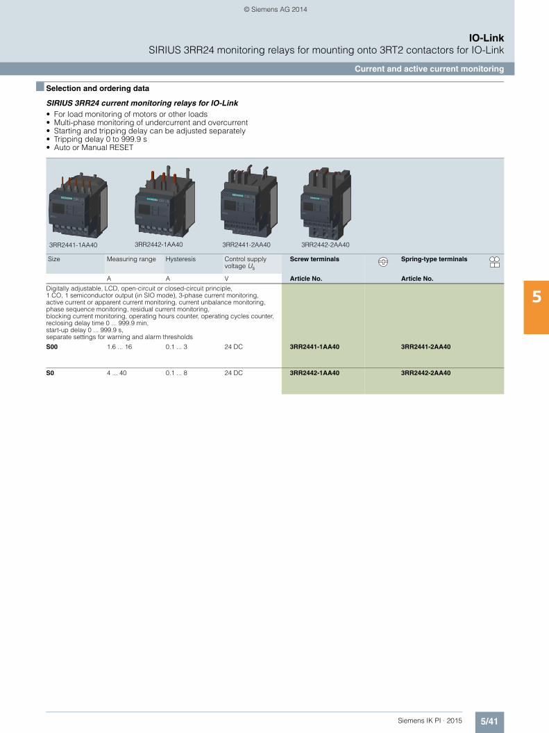
5/41Siemens IK PI · 2015
IO-LinkSIRIUS 3RR24 monitoring relays for mounting onto 3RT2 contactors for IO-Link
Current and active current monitoring
5
■ Selection and ordering data
SIRIUS 3RR24 current monitoring relays for IO-Link• For load monitoring of motors or other loads• Multi-phase monitoring of undercurrent and overcurrent• Starting and tripping delay can be adjusted separately• Tripping delay 0 to 999.9 s• Auto or Manual RESET
Size Measuring range Hysteresis Control supply voltage Us
Screw terminals Spring-type terminals
A A V Article No. Article No.
Digitally adjustable, LCD, open-circuit or closed-circuit principle, 1 CO, 1 semiconductor output (in SIO mode), 3-phase current monitoring, active current or apparent current monitoring, current unbalance monitoring, phase sequence monitoring, residual current monitoring, blocking current monitoring, operating hours counter, operating cycles counter, reclosing delay time 0 ... 999.9 min, start-up delay 0 ... 999.9 s, separate settings for warning and alarm thresholds
S00 1.6 ... 16 0.1 ... 3 24 DC 3RR2441-1AA40 3RR2441-2AA40
S0 4 ... 40 0.1 ... 8 24 DC 3RR2442-1AA40 3RR2442-2AA40
3RR2441-1AA40 3RR2442-1AA40 3RR2441-2AA40 3RR2442-2AA40
IKPI_05_en.book Seite 41 Montag, 6. Oktober 2014 4:09 16
© Siemens AG 2014
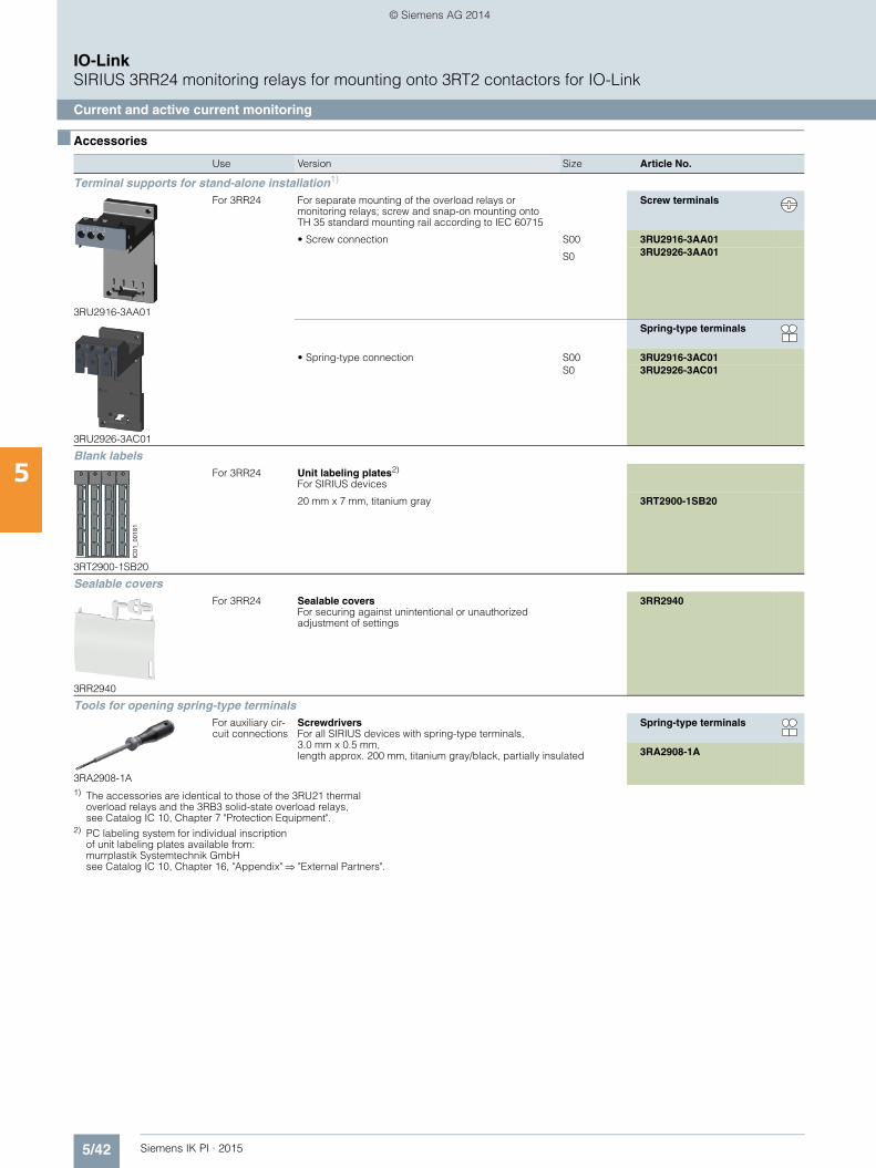
5/42 Siemens IK PI · 2015
IO-LinkSIRIUS 3RR24 monitoring relays for mounting onto 3RT2 contactors for IO-Link
Current and active current monitoring
5
■ Accessories
1) The accessories are identical to those of the 3RU21 thermal overload relays and the 3RB3 solid-state overload relays, see Catalog IC 10, Chapter 7 "Protection Equipment".
2) PC labeling system for individual inscriptionof unit labeling plates available from:murrplastik Systemtechnik GmbHsee Catalog IC 10, Chapter 16, "Appendix" "External Partners".
Use Version Size Article No.
Terminal supports for stand-alone installation1)
3RU2916-3AA01
For 3RR24 For separate mounting of the overload relays or monitoring relays; screw and snap-on mounting onto TH 35 standard mounting rail according to IEC 60715
Screw terminals
• Screw connection S00 3RU2916-3AA01
S0 3RU2926-3AA01
3RU2926-3AC01
Spring-type terminals
• Spring-type connection S00 3RU2916-3AC01S0 3RU2926-3AC01
Blank labels
3RT2900-1SB20
For 3RR24 Unit labeling plates2)
For SIRIUS devices
20 mm x 7 mm, titanium gray 3RT2900-1SB20
Sealable covers
3RR2940
For 3RR24 Sealable coversFor securing against unintentional or unauthorized adjustment of settings
3RR2940
Tools for opening spring-type terminals
3RA2908-1A
For auxiliary cir-cuit connections
Screwdrivers For all SIRIUS devices with spring-type terminals, 3.0 mm x 0.5 mm, length approx. 200 mm, titanium gray/black, partially insulated
Spring-type terminals
3RA2908-1A
IC01
_001
81
IKPI_05_en.book Seite 42 Montag, 6. Oktober 2014 4:09 16
© Siemens AG 2014
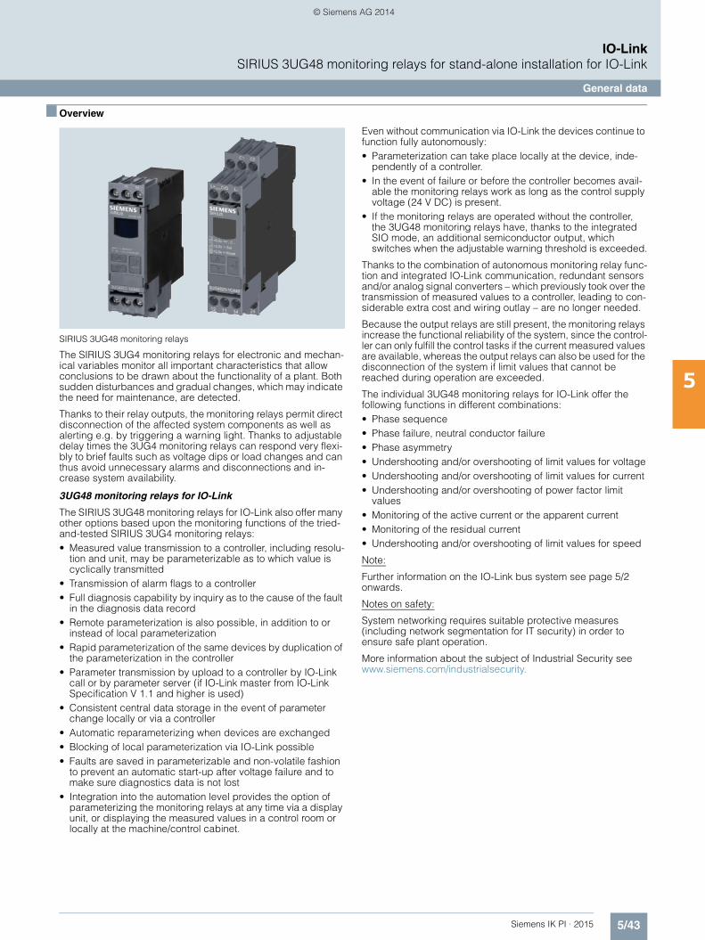
5/43Siemens IK PI · 2015
IO-LinkSIRIUS 3UG48 monitoring relays for stand-alone installation for IO-Link
General data
5
■ Overview
SIRIUS 3UG48 monitoring relays
The SIRIUS 3UG4 monitoring relays for electronic and mechan-ical variables monitor all important characteristics that allow conclusions to be drawn about the functionality of a plant. Both sudden disturbances and gradual changes, which may indicate the need for maintenance, are detected.
Thanks to their relay outputs, the monitoring relays permit direct disconnection of the affected system components as well as alerting e.g. by triggering a warning light. Thanks to adjustable delay times the 3UG4 monitoring relays can respond very flexi-bly to brief faults such as voltage dips or load changes and can thus avoid unnecessary alarms and disconnections and in-crease system availability.
3UG48 monitoring relays for IO-Link
The SIRIUS 3UG48 monitoring relays for IO-Link also offer many other options based upon the monitoring functions of the tried-and-tested SIRIUS 3UG4 monitoring relays:• Measured value transmission to a controller, including resolu-
tion and unit, may be parameterizable as to which value is cyclically transmitted
• Transmission of alarm flags to a controller• Full diagnosis capability by inquiry as to the cause of the fault
in the diagnosis data record• Remote parameterization is also possible, in addition to or
instead of local parameterization• Rapid parameterization of the same devices by duplication of
the parameterization in the controller• Parameter transmission by upload to a controller by IO-Link
call or by parameter server (if IO-Link master from IO-Link Specification V 1.1 and higher is used)
• Consistent central data storage in the event of parameter change locally or via a controller
• Automatic reparameterizing when devices are exchanged• Blocking of local parameterization via IO-Link possible• Faults are saved in parameterizable and non-volatile fashion
to prevent an automatic start-up after voltage failure and to make sure diagnostics data is not lost
• Integration into the automation level provides the option of parameterizing the monitoring relays at any time via a display unit, or displaying the measured values in a control room or locally at the machine/control cabinet.
Even without communication via IO-Link the devices continue to function fully autonomously:• Parameterization can take place locally at the device, inde-
pendently of a controller. • In the event of failure or before the controller becomes avail-
able the monitoring relays work as long as the control supply voltage (24 V DC) is present.
• If the monitoring relays are operated without the controller, the 3UG48 monitoring relays have, thanks to the integrated SIO mode, an additional semiconductor output, which switches when the adjustable warning threshold is exceeded.
Thanks to the combination of autonomous monitoring relay func-tion and integrated IO-Link communication, redundant sensors and/or analog signal converters – which previously took over the transmission of measured values to a controller, leading to con-siderable extra cost and wiring outlay – are no longer needed.
Because the output relays are still present, the monitoring relays increase the functional reliability of the system, since the control-ler can only fulfill the control tasks if the current measured values are available, whereas the output relays can also be used for the disconnection of the system if limit values that cannot be reached during operation are exceeded.
The individual 3UG48 monitoring relays for IO-Link offer the following functions in different combinations:• Phase sequence• Phase failure, neutral conductor failure• Phase asymmetry• Undershooting and/or overshooting of limit values for voltage• Undershooting and/or overshooting of limit values for current• Undershooting and/or overshooting of power factor limit
values• Monitoring of the active current or the apparent current• Monitoring of the residual current• Undershooting and/or overshooting of limit values for speed
Note:
Further information on the IO-Link bus system see page 5/2 onwards.
Notes on safety:
System networking requires suitable protective measures (including network segmentation for IT security) in order to ensure safe plant operation.
More information about the subject of Industrial Security see www.siemens.com/industrialsecurity.
IKPI_05_en.book Seite 43 Montag, 6. Oktober 2014 4:09 16
© Siemens AG 2014
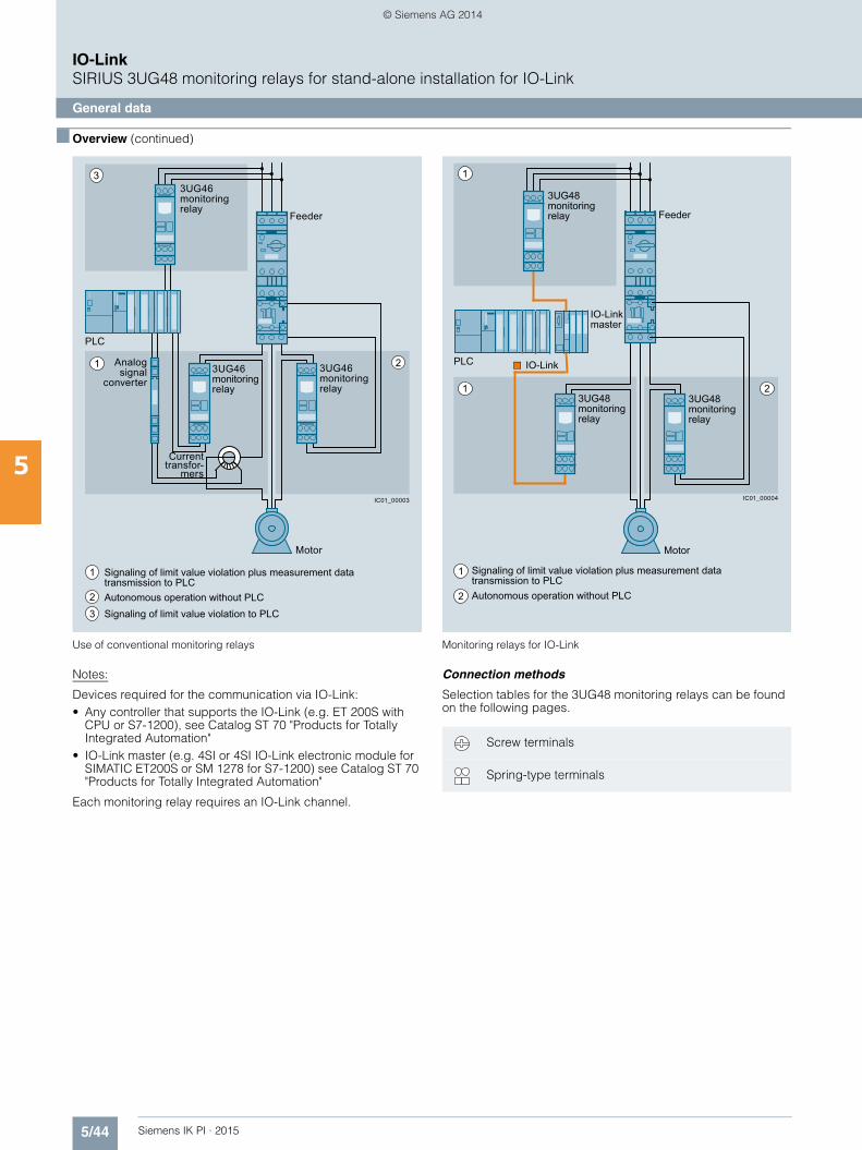
5/44 Siemens IK PI · 2015
IO-LinkSIRIUS 3UG48 monitoring relays for stand-alone installation for IO-Link
General data
5
■ Overview (continued)
Use of conventional monitoring relays Monitoring relays for IO-Link
Notes:
Devices required for the communication via IO-Link:• Any controller that supports the IO-Link (e.g. ET 200S with
CPU or S7-1200), see Catalog ST 70 "Products for Totally Integrated Automation"
• IO-Link master (e.g. 4SI or 4SI IO-Link electronic module for SIMATIC ET200S or SM 1278 for S7-1200) see Catalog ST 70 "Products for Totally Integrated Automation"
Each monitoring relay requires an IO-Link channel.
Connection methods
Selection tables for the 3UG48 monitoring relays can be found on the following pages.
3
1 2
Feeder
PLC
Motor
3UG46monitoring relay
3UG46monitoring relay
3UG46monitoring relay
Analog signal
converter
Current transfor-
mers
Autonomous operation without PLC
Signaling of limit value violation plus measurement data transmission to PLC
Signaling of limit value violation to PLC
1
23
IC01_00003
2
1
1
PLC
IO-Link master
3UG48monitoring relay
3UG48monitoring relay
3UG48monitoring relay Feeder
Autonomous operation without PLC
Signaling of limit value violation plus measurement data transmission to PLC
2
Motor
1
IC01_00004
IO-Link
Screw terminals
Spring-type terminals
IKPI_05_en.book Seite 44 Montag, 6. Oktober 2014 4:09 16
© Siemens AG 2014

5/45Siemens IK PI · 2015
IO-LinkSIRIUS 3UG48 monitoring relays for stand-alone installation for IO-Link
General data
5
■ Benefits
• Simple cyclical transmission of the current measured values, relay switching states and events to a controller
• Remote parameterization• Automatic reparameterizing when devices are exchanged• Simple duplication of identical or similar parameterizations• Reduction of control current wiring • Elimination of testing costs and wiring errors• Reduction of configuration work• Integration in TIA means clear diagnostics if a fault occurs• Cost saving and space saving in control cabinet due to the
elimination of AI and IO modules as well as analog signal converters and duplicated sensors
■ Application
The use of SIRIUS monitoring relays for IO-Link is particularly recommended for machines and plant in which these relays, in addition to their monitoring function, are to be connected to the automation level for the rapid, simple and fault-free provision of the current measured values and/or for remote parameterization.
The monitoring relays can either relieve the controller of monitor-ing tasks or, as a second monitoring entity in parallel to and in-dependent of the controller, increase the reliability in the process or in the system. In addition, the elimination of AI and IO modules allows the width of the controller to be reduced despite signifi-cantly expanded functionality.
■ More information
Manual "3UG48/3RR24 Monitoring Relays for IO-Link" see http://support.automation.siemens.com/WW/view/en/54375430.
Notes on safety:
System networking requires suitable protective measures (including network segmentation for IT security) in order to ensure safe plant operation.
More information about the subject of Industrial Security see www.siemens.com/industrialsecurity.
IKPI_05_en.book Seite 45 Montag, 6. Oktober 2014 4:09 16
© Siemens AG 2014
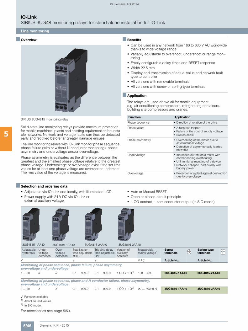
5/46 Siemens IK PI · 2015
IO-LinkSIRIUS 3UG48 monitoring relays for stand-alone installation for IO-Link
Line monitoring
5
■ Overview
SIRIUS 3UG4815 monitoring relay
Solid-state line monitoring relays provide maximum protection for mobile machines, plants and hoisting equipment or for unsta-ble networks. Network and voltage faults can thus be detected early and rectified before far greater damage ensues.
The line monitoring relays with IO-Link monitor phase sequence, phase failure (with or without N conductor monitoring), phase asymmetry and undervoltage and/or overvoltage.
Phase asymmetry is evaluated as the difference between the greatest and the smallest phase voltage relative to the greatest phase voltage. Undervoltage or overvoltage exist if the set limit values for at least one phase voltage are overshot or undershot. The rms value of the voltage is measured.
■ Benefits
• Can be used in any network from 160 to 630 V AC worldwide thanks to wide voltage range
• Variably adjustable to overshoot, undershoot or range moni-toring
• Freely configurable delay times and RESET response• Width 22.5 mm• Display and transmission of actual value and network fault
type to controller• All versions with removable terminals• All versions with screw or spring-type terminals
■ Application
The relays are used above all for mobile equipment, e.g. air conditioning compressors, refrigerating containers, building site compressors and cranes.
■ Selection and ordering data
• Adjustable via IO-Link and locally, with illuminated LCD• Power supply with 24 V DC via IO-Link or
external auxiliary voltage
• Auto or Manual RESET• Open or closed-circuit principle• 1 CO contact, 1 semiconductor output (in SIO mode)
✓ Function available1) Absolute limit values.2) In SIO mode.
For accessories see page 5/53.
Function Application
Phase sequence • Direction of rotation of the drive
Phase failure • A fuse has tripped• Failure of the control supply voltage• Broken cable
Phase asymmetry • Overheating of the motor due to asymmetrical voltage
• Detection of asymmetrically loaded networks
Undervoltage • Increased current on a motor with corresponding overheating
• Unintentional resetting of a device • Network collapse, particularly with
battery power
Overvoltage • Protection of a plant against destruction due to overvoltage
Adjustable hysteresis
Under-voltagedetection
Over-voltagedetection
Stabilization time adjustable stDEL
Tripping delay time adjustable Del
Version of auxiliary contacts
Measurable mains voltage1)
Screw terminals
Spring-type terminals
V s s V AC Article No. Article No.
Monitoring of phase sequence, phase failure, phase asymmetry, overvoltage and undervoltage 1 ... 20 ✓ ✓ 0.1 … 999.9 0.1 … 999.9 1 CO + 1 Q2) 160 … 690 3UG4815-1AA40 3UG4815-2AA40
Monitoring of phase sequence, phase and N conductor failure, phase asymmetry, overvoltage and undervoltage 1 ... 20 ✓ ✓ 0.1 … 999.9 0.1 … 999.9 1 CO + 1 Q2) 90 … 400 to N 3UG4816-1AA40 3UG4816-2AA40
3UG4815-1AA40 3UG4816-1AA40 3UG4815-2AA40 3UG4816-2AA40
IKPI_05_en.book Seite 46 Montag, 6. Oktober 2014 4:09 16
© Siemens AG 2014

5/47Siemens IK PI · 2015
IO-LinkSIRIUS 3UG48 monitoring relays for stand-alone installation for IO-Link
Voltage monitoring
5
■ Overview
SIRIUS 3UG4832 monitoring relays
The relays monitor single-phase AC voltages (rms value) and DC voltages against the set limit value for overshoot and under-shoot.
■ Benefits
• Variably adjustable to overshoot, undershoot or range monitoring
• Freely configurable delay times and RESET response• Width 22.5 mm• Display and transmission of actual value and status messages
to controller• All versions with removable terminals• All versions with screw or spring-type terminals
■ Application
• Protection of a plant against destruction due to overvoltage• Switch-on of a plant at a defined voltage and higher• Protection from undervoltage due to overloaded control
supply voltages, particularly with battery power
■ Selection and ordering data
• Adjustable via IO-Link and locally, with illuminated LCD• Power supply with 24 V DC via IO-Link or external auxiliary
voltage• Auto or Manual RESET• Open or closed-circuit principle• 1 CO contact, 1 semiconductor output (in SIO mode)
For accessories see page 5/53.
Measuring range Adjustable hysteresis
ON-delay time adjustable onDel
Tripping delay time separately adjustable U▲Del/U▼Del
Screw terminals
Spring-type terminals
V AC/DC V s s Article No. Article No.
Monitoring of voltage for overshoot and undershoot10 … 600 0.1 ... 300 0 … 999.9 0 … 999.9 3UG4832-1AA40 3UG4832-2AA40
3UG4832-1AA40 3UG4832-2AA40
IKPI_05_en.book Seite 47 Montag, 6. Oktober 2014 4:09 16
© Siemens AG 2014

5/48 Siemens IK PI · 2015
IO-LinkSIRIUS 3UG48 monitoring relays for stand-alone installation for IO-Link
Current monitoring
5
■ Overview
SIRIUS 3UG4822 monitoring relays
The relays monitor single-phase AC (rms value) and DC currents against the set limit value for overshoot and undershoot.
■ Benefits
• Variably adjustable to overshoot, undershoot or range moni-toring
• Freely configurable delay times and RESET response
• Width 22.5 mm• Display and transmission of actual value and status messages
to controller• All versions with removable terminals• All versions with screw or spring-type terminals
■ Application
• Overcurrent and undercurrent monitoring• Monitoring the functionality of electrical
loads• Monitoring for broken conductors
■ Selection and ordering data
• Adjustable via IO-Link and locally, with illuminated LCD• Power supply with 24 V DC via IO-Link or
external auxiliary voltage• Adjustable converter factor to display the measured primary
current when external current transformer used• Auto or Manual RESET• Open or closed-circuit principle• 1 CO contact, 1 semiconductor output (in SIO mode)
For accessories see page 5/53.
For AC currents I > 10 A it is possible to use commercially available current transformers, e.g. the Siemens 4NC current transformer, as accessories, see Catalog LV 10, "Low-Voltage Power Distribution and Electrical Installation Technology".
Measuring range Adjustable hysteresis
ON-delay time adjustable onDel
Tripping delay time separately adjustable U▲Del/U▼Del
Screw terminals
Spring-type terminals
AC/DC A A s s Article No. Article No.
Monitoring of current for overshooting and undershooting 0.05 … 10 0.01 ... 5 0.1 … 999.9 0.1 … 999.9 3UG4822-1AA40 3UG4822-2AA40
3UG4822-1AA40 3UG4822-2AA40
IKPI_05_en.book Seite 48 Montag, 6. Oktober 2014 4:09 16
© Siemens AG 2014
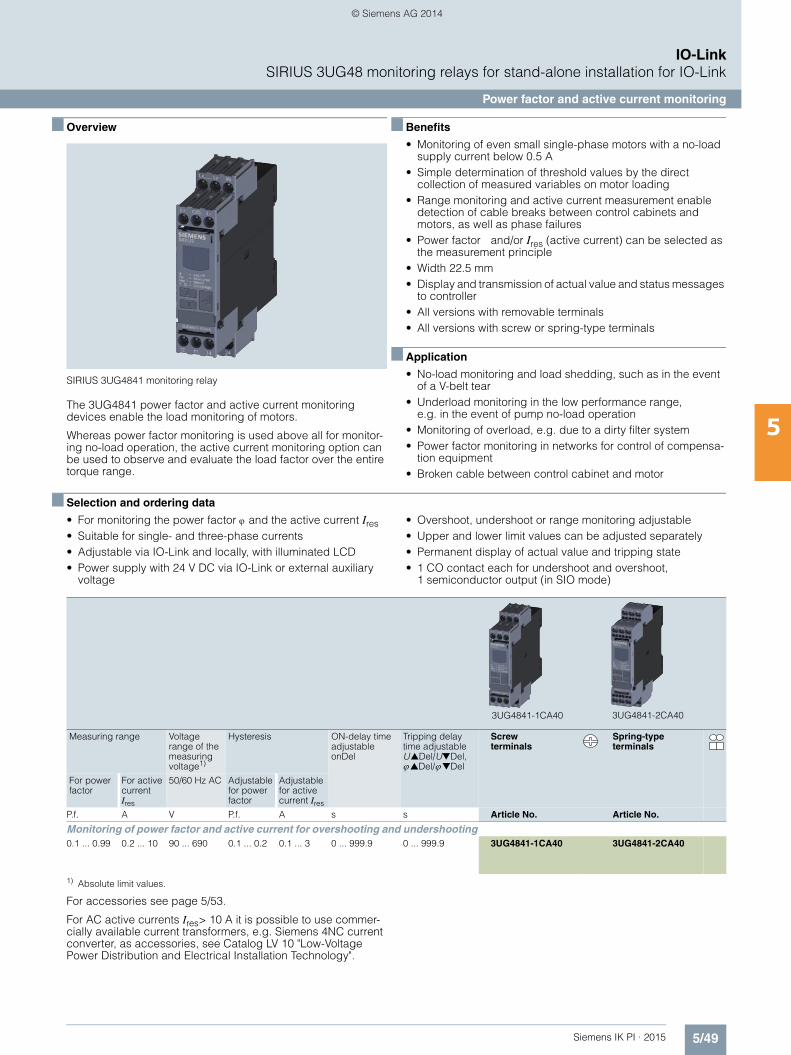
5/49Siemens IK PI · 2015
IO-LinkSIRIUS 3UG48 monitoring relays for stand-alone installation for IO-Link
Power factor and active current monitoring
5
■ Overview
SIRIUS 3UG4841 monitoring relay
The 3UG4841 power factor and active current monitoring devices enable the load monitoring of motors.
Whereas power factor monitoring is used above all for monitor-ing no-load operation, the active current monitoring option can be used to observe and evaluate the load factor over the entire torque range.
■ Benefits
• Monitoring of even small single-phase motors with a no-load supply current below 0.5 A
• Simple determination of threshold values by the direct collection of measured variables on motor loading
• Range monitoring and active current measurement enable detection of cable breaks between control cabinets and motors, as well as phase failures
• Power factor and/or Ires (active current) can be selected as the measurement principle
• Width 22.5 mm• Display and transmission of actual value and status messages
to controller• All versions with removable terminals• All versions with screw or spring-type terminals
■ Application
• No-load monitoring and load shedding, such as in the event of a V-belt tear
• Underload monitoring in the low performance range, e.g. in the event of pump no-load operation
• Monitoring of overload, e.g. due to a dirty filter system• Power factor monitoring in networks for control of compensa-
tion equipment• Broken cable between control cabinet and motor
■ Selection and ordering data
• For monitoring the power factor and the active current Ires • Suitable for single- and three-phase currents• Adjustable via IO-Link and locally, with illuminated LCD• Power supply with 24 V DC via IO-Link or external auxiliary
voltage
• Overshoot, undershoot or range monitoring adjustable• Upper and lower limit values can be adjusted separately• Permanent display of actual value and tripping state• 1 CO contact each for undershoot and overshoot,
1 semiconductor output (in SIO mode)
1) Absolute limit values.
For accessories see page 5/53.
For AC active currents Ires> 10 A it is possible to use commer-cially available current transformers, e.g. Siemens 4NC current converter, as accessories, see Catalog LV 10 "Low-Voltage Power Distribution and Electrical Installation Technology".
Measuring range Voltage range of the measuring voltage1)
Hysteresis ON-delay time adjustable onDel
Tripping delay time adjustable U▲Del/U▼Del, ▲Del/▼Del
Screw terminals
Spring-type terminals
For power factor
For active current Ires
50/60 Hz AC Adjustable for power factor
Adjustable for active current Ires
P.f. A V P.f. A s s Article No. Article No.
Monitoring of power factor and active current for overshooting and undershooting0.1 ... 0.99 0.2 ... 10 90 ... 690 0.1 ... 0.2 0.1 ... 3 0 ... 999.9 0 ... 999.9 3UG4841-1CA40 3UG4841-2CA40
3UG4841-1CA40 3UG4841-2CA40
IKPI_05_en.book Seite 49 Montag, 6. Oktober 2014 4:09 16
© Siemens AG 2014

5/50 Siemens IK PI · 2015
IO-LinkSIRIUS 3UG48 monitoring relays for stand-alone installation for IO-LinkResidual current monitoring
Residual-current monitoring relays
5
■ Overview
SIRIUS 3UG4825 monitoring relay
The 3UG4825 residual-current monitoring relays are used in conjunction with the 3UL23 residual current transformers for monitoring plants in which higher residual currents are increas-ingly expected due to environmental conditions. Monitoring encompasses pure AC residual currents or AC residual currents with a pulsating DC fault current component (transformer type A in accordance with DIN VDE 0100-530/IEC TR 60755).
■ Benefits
• High measuring accuracy ± 7.5%• Permanent self-monitoring• Parameterization of the devices locally or via IO-Link possible• Variable threshold values for warning and disconnection• Freely configurable delay times and RESET response• Display and transmission of actual value and status messages
to controller• High level of flexibility and space saving through installation of
the transformer inside or outside the control cabinet• Width 22.5 m• All versions with removable terminals• All versions with screw or spring-type terminals
■ Application
Monitoring of plants in which residual currents can occur, e.g. due to dust deposits or moisture, porous cables and leads, or capacitive residual currents
■ Selection and ordering data
• For monitoring residual currents from 0.03 to 40 A, from 16 to 400 Hz
• For 3UL23 residual-current transformers with feed-through opening from 35 to 210 mm
• Permanent self-monitoring• Certified in accordance with IEC 60947, functionality corre-
sponds to IEC 62020• Digitally adjustable, with illuminated LCD• Permanent display of actual value and tripping state• Separately adjustable limit value and warning threshold• 1 changeover contact each for warning threshold and tripping
threshold
For accessories see page 5/53.
3UL23 residual-current transformers and accessories for 3UL23 see page 5/51.
Measurable current
Adjustable response value current
Switching hysteresis
Adjustable response delay time
Control supply voltage
Screw terminals
Spring-type terminals
At DC, rated value
A A % s V Article No. Article No.
0.01 ... 43 0.03 ... 40 0 ... 50 0 ... 999.9 24 3UG4825-1CA40 3UG4825-2CA40
3UG4825-1CA40 3UG4825-2CA40
IKPI_05_en.book Seite 50 Montag, 6. Oktober 2014 4:09 16
© Siemens AG 2014
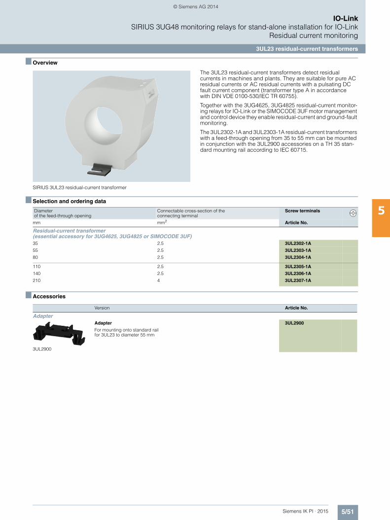
5/51Siemens IK PI · 2015
IO-LinkSIRIUS 3UG48 monitoring relays for stand-alone installation for IO-Link
Residual current monitoring
3UL23 residual-current transformers
5
■ Overview
SIRIUS 3UL23 residual-current transformer
The 3UL23 residual-current transformers detect residual currents in machines and plants. They are suitable for pure AC residual currents or AC residual currents with a pulsating DC fault current component (transformer type A in accordance with DIN VDE 0100-530/IEC TR 60755).
Together with the 3UG4625, 3UG4825 residual-current monitor-ing relays for IO-Link or the SIMOCODE 3UF motor management and control device they enable residual-current and ground-fault monitoring.
The 3UL2302-1A and 3UL2303-1A residual-current transformers with a feed-through opening from 35 to 55 mm can be mounted in conjunction with the 3UL2900 accessories on a TH 35 stan-dard mounting rail according to IEC 60715.
■ Selection and ordering data
■ Accessories
Diameter of the feed-through opening
Connectable cross-section of the connecting terminal
Screw terminals
mm mm2 Article No.
Residual-current transformer (essential accessory for 3UG4625, 3UG4825 or SIMOCODE 3UF)
35 2.5 3UL2302-1A
55 2.5 3UL2303-1A
80 2.5 3UL2304-1A
110 2.5 3UL2305-1A
140 2.5 3UL2306-1A
210 4 3UL2307-1A
Version Article No.
Adapter
3UL2900
Adapter
For mounting onto standard railfor 3UL23 to diameter 55 mm
3UL2900
IKPI_05_en.book Seite 51 Montag, 6. Oktober 2014 4:09 16
© Siemens AG 2014
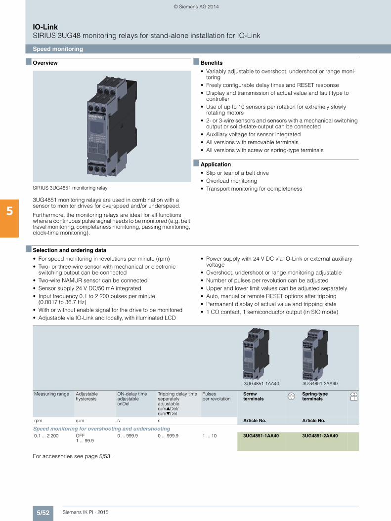
5/52 Siemens IK PI · 2015
IO-LinkSIRIUS 3UG48 monitoring relays for stand-alone installation for IO-Link
Speed monitoring
5
■ Overview
SIRIUS 3UG4851 monitoring relay
3UG4851 monitoring relays are used in combination with a sensor to monitor drives for overspeed and/or underspeed.
Furthermore, the monitoring relays are ideal for all functions where a continuous pulse signal needs to be monitored (e.g. belt travel monitoring, completeness monitoring, passing monitoring, clock-time monitoring).
■ Benefits
• Variably adjustable to overshoot, undershoot or range moni-toring
• Freely configurable delay times and RESET response• Display and transmission of actual value and fault type to
controller• Use of up to 10 sensors per rotation for extremely slowly
rotating motors• 2- or 3-wire sensors and sensors with a mechanical switching
output or solid-state-output can be connected• Auxiliary voltage for sensor integrated• All versions with removable terminals• All versions with screw or spring-type terminals
■ Application
• Slip or tear of a belt drive• Overload monitoring• Transport monitoring for completeness
■ Selection and ordering data
• For speed monitoring in revolutions per minute (rpm)• Two- or three-wire sensor with mechanical or electronic
switching output can be connected• Two-wire NAMUR sensor can be connected• Sensor supply 24 V DC/50 mA integrated• Input frequency 0.1 to 2 200 pulses per minute
(0.0017 to 36.7 Hz)• With or without enable signal for the drive to be monitored• Adjustable via IO-Link and locally, with illuminated LCD
• Power supply with 24 V DC via IO-Link or external auxiliary voltage
• Overshoot, undershoot or range monitoring adjustable• Number of pulses per revolution can be adjusted• Upper and lower limit values can be adjusted separately• Auto, manual or remote RESET options after tripping• Permanent display of actual value and tripping state• 1 CO contact, 1 semiconductor output (in SIO mode)
For accessories see page 5/53.
Measuring range Adjustable hysteresis
ON-delay time adjustable onDel
Tripping delay time separately adjustable rpm▲Del/rpm▼Del
Pulsesper revolution
Screw terminals
Spring-type terminals
rpm rpm s s Article No. Article No.
Speed monitoring for overshooting and undershooting0.1 ... 2 200 OFF
1 ... 99.90 ... 999.9 0 ... 999.9 1 ... 10 3UG4851-1AA40 3UG4851-2AA40
3UG4851-1AA40 3UG4851-2AA40
IKPI_05_en.book Seite 52 Montag, 6. Oktober 2014 4:09 16
© Siemens AG 2014
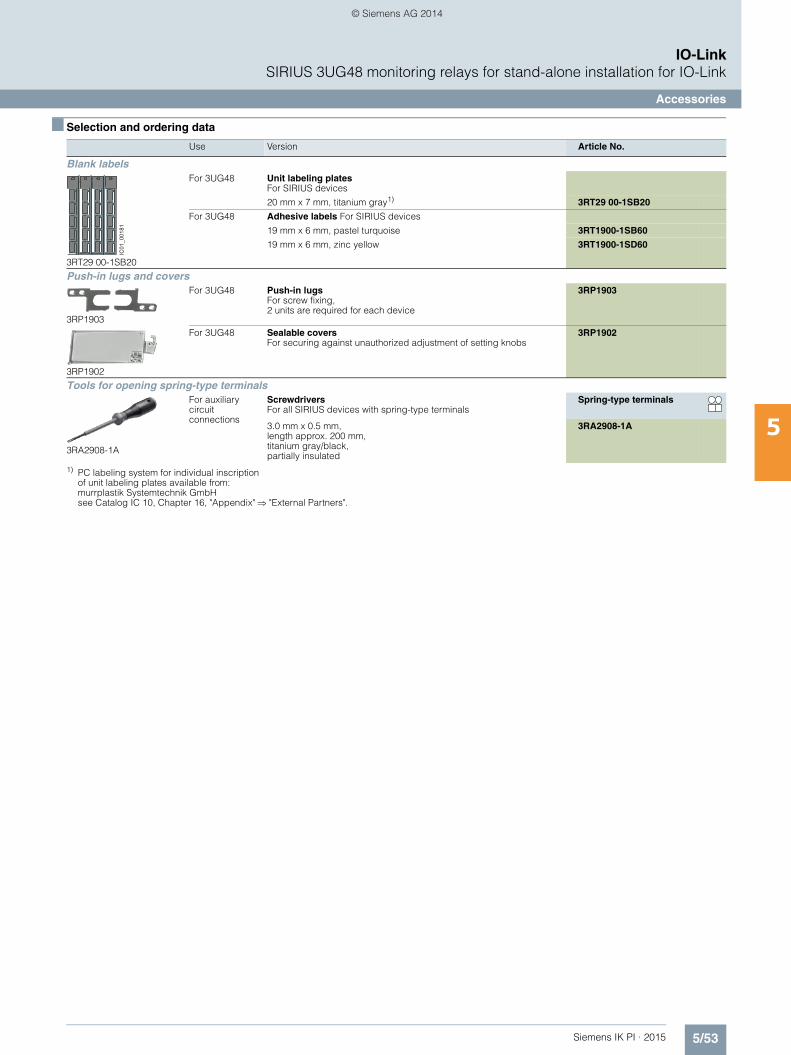
5/53Siemens IK PI · 2015
IO-LinkSIRIUS 3UG48 monitoring relays for stand-alone installation for IO-Link
Accessories
5
■ Selection and ordering data
1) PC labeling system for individual inscriptionof unit labeling plates available from:murrplastik Systemtechnik GmbHsee Catalog IC 10, Chapter 16, "Appendix" "External Partners".
Use Version Article No.
Blank labels
3RT29 00-1SB20
For 3UG48 Unit labeling plates For SIRIUS devices
20 mm x 7 mm, titanium gray1) 3RT29 00-1SB20
For 3UG48 Adhesive labels For SIRIUS devices
19 mm x 6 mm, pastel turquoise 3RT1900-1SB60
19 mm x 6 mm, zinc yellow 3RT1900-1SD60
Push-in lugs and covers
3RP1903
For 3UG48 Push-in lugs For screw fixing,2 units are required for each device
3RP1903
3RP1902
For 3UG48 Sealable covers For securing against unauthorized adjustment of setting knobs
3RP1902
Tools for opening spring-type terminals
3RA2908-1A
For auxiliary circuit connections
Screwdrivers For all SIRIUS devices with spring-type terminals
Spring-type terminals
3.0 mm x 0.5 mm, length approx. 200 mm, titanium gray/black, partially insulated
3RA2908-1A
IC01
_001
81
IKPI_05_en.book Seite 53 Montag, 6. Oktober 2014 4:09 16
© Siemens AG 2014
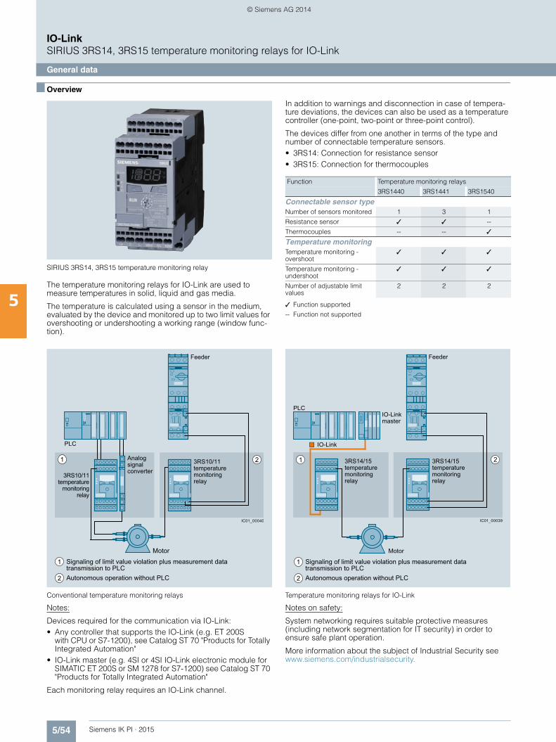
5/54 Siemens IK PI · 2015
IO-LinkSIRIUS 3RS14, 3RS15 temperature monitoring relays for IO-Link
General data
5
■ Overview
SIRIUS 3RS14, 3RS15 temperature monitoring relay
The temperature monitoring relays for IO-Link are used to measure temperatures in solid, liquid and gas media.
The temperature is calculated using a sensor in the medium, evaluated by the device and monitored up to two limit values for overshooting or undershooting a working range (window func-tion).
In addition to warnings and disconnection in case of tempera-ture deviations, the devices can also be used as a temperature controller (one-point, two-point or three-point control).
The devices differ from one another in terms of the type and number of connectable temperature sensors.• 3RS14: Connection for resistance sensor• 3RS15: Connection for thermocouples
✓ Function supported
-- Function not supported
Conventional temperature monitoring relays
Notes:
Devices required for the communication via IO-Link:• Any controller that supports the IO-Link (e.g. ET 200S
with CPU or S7-1200), see Catalog ST 70 "Products for Totally Integrated Automation"
• IO-Link master (e.g. 4SI or 4SI IO-Link electronic module for SIMATIC ET 200S or SM 1278 for S7-1200) see Catalog ST 70 "Products for Totally Integrated Automation"
Each monitoring relay requires an IO-Link channel.
Temperature monitoring relays for IO-Link
Notes on safety:
System networking requires suitable protective measures (including network segmentation for IT security) in order to ensure safe plant operation.
More information about the subject of Industrial Security see www.siemens.com/industrialsecurity.
Function Temperature monitoring relays
3RS1440 3RS1441 3RS1540
Connectable sensor typeNumber of sensors monitored 1 3 1
Resistance sensor ✓ ✓ --
Thermocouples -- -- ✓
Temperature monitoringTemperature monitoring - overshoot
✓ ✓ ✓
Temperature monitoring - undershoot
✓ ✓ ✓
Number of adjustable limit values
2 2 2
1 2
Feeder
1
2
PLC
Motor
Autonomous operation without PLC
Signaling of limit value violation plus measurement data transmission to PLC
Analog signal converter
3RS10/11temperature
monitoring relay
3RS10/11temperature monitoring relay
IC01_00040
21
1
2
PLCIO-Link master
Feeder
Autonomous operation without PLC
Signaling of limit value violation plus measurement data transmission to PLC
Motor
3RS14/15temperature monitoringrelay
3RS14/15temperature monitoring relay
IC01_00039
IO-Link
IKPI_05_en.book Seite 54 Montag, 6. Oktober 2014 4:09 16
© Siemens AG 2014
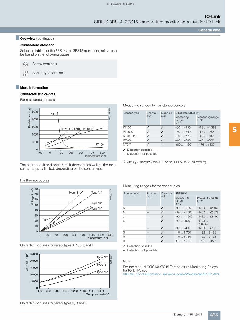
5/55Siemens IK PI · 2015
IO-LinkSIRIUS 3RS14, 3RS15 temperature monitoring relays for IO-Link
General data
5
■ Overview (continued)
Connection methods
Selection tables for the 3RS14 and 3RS15 monitoring relays can be found on the following pages.
■ More information
Characteristic curves
For resistance sensors
The short-circuit and open-circuit detection as well as the mea-suring range is limited, depending on the sensor type.
Measuring ranges for resistance sensors
✓ Detection possible-- Detection not possible
1) NTC type: B57227-K333-A1 (100 °C: 1.8 k; 25 °C: 32.762 k).
For thermocouples
Characteristic curves for sensor types K, N, J, E and T
Characteristic curves for sensor types S, R and B
Measuring ranges for thermocouples
✓ Detection possible-- Detection not possible
Note:
For the manual "3RS14/3RS15 Temperature Monitoring Relays for IO-Link", seehttp://support.automation.siemens.com/WW/view/en/54375463.
Screw terminals
Spring-type terminals
5 000
4 000
3 000
2 000
1 000
0
NTC
KTY83 KTY84 PT1000
PT100
NS
B0_
0132
2a
-100 100 200 300 400 5000Temperature in °C
Res
ista
nce
in
Sensor type Short cir-cuit
Open cir-cuit
3RS1440, 3RS1441
Measuring range in °C
Measuring range in °F
PT100 ✓ ✓ –50 ... +750 –58 ... +1 382
PT1000 ✓ ✓ –50 ... +500 –58 ... +932
KTY83-110 ✓ ✓ –50 ... +175 –58 ... +347
KTY84 ✓ ✓ –40 ... +300 –40 ... +572
NTC1) ✓ -- +80 ... +160 +176 ... +320
80
70
60
50
40
30
20
10
0
NS
B0_
0132
1a
0 200 400 500 800 1 000 1 200 1 400 1 600Temperature in °C
Type "E" Type "J"
Type "K"
Type "N"
Type "T"
Volta
ge in
mV
IC01
_000
4425 000
20 000
15 000
10 000
5 000
0400 600 800 1 000 1 200 1 400 1 600 1 800
Temperature in °C
Type "R"
Type "S"
Type "B"
Sensor type Short cir-cuit
Open cir-cuit
3RS1540
Measuring range in °C
Measuring range in °F
K -- ✓ -99 ... +1 350 -146.2 ... +2 462
N -- ✓ -99 ... +1 300 -146.2 ... +2 372
J -- ✓ -99 ... +1 200 -146.2 ... +2 192
E -- ✓ -99 ... +999 -146.2 ... +1 830.2
T -- ✓ -99 ... +400 -146.2 ... +752
S -- ✓ 0 ... 1 750 32 ... 3 182
R -- ✓ 0 ... 1 750 32 ... 3 182
B -- ✓ 400 ... 1 800 752 ... 3 272
IKPI_05_en.book Seite 55 Montag, 6. Oktober 2014 4:09 16
© Siemens AG 2014

5/56 Siemens IK PI · 2015
IO-LinkSIRIUS 3RS14, 3RS15 temperature monitoring relays for IO-Link
Relays, digitally adjustable for 1 sensor
5
■ Overview
SIRIUS 3RS1440 digital monitoring relay for 1 sensor
The 3RS14 and 3RS15 temperature monitoring relays for IO-Link are used to measure temperatures in solid, liquid and gas media. The temperature is calculated using a sensor in the medium, evaluated by the device and monitored for overshoot-ing or undershooting a working range (window function). The digital temperature monitoring relays have two separately adjustable limit values, are non-volatile and can be operated as desired using the open- or closed-circuit principle.
The devices differ in terms of the number of temperature sensors which can be evaluated. The 3RS1440 and 3RS1540 for IO-Link temperature monitoring relays can be digitally adjusted for one sensor and represent an alternative to temperature controllers in the low-end range (two-point or three-point control).
The devices with two-point control can, for example, be used as a thermostat. The devices with three-point control can, for exam-ple, independently switch between heating and cooling.
The 3RS1441 temperature monitoring relays for IO-Link can be digitally adjusted to evaluate up to three resistance sensors at one time. The devices were designed specifically for monitoring motor windings and positions.
The temperature monitoring relays are powered through the control supply voltages IO-Link (L+) and ground (L-) or via an external 24 V DC power supply.
Monitoring
When the temperature has reached the 1 limit value, the K1 output relay changes its switching state after the configured time t has expired (output relay K2 reacts accordingly at 2). The delay time can be adjusted.
The output relays return immediately to their original state once the temperature reaches the respective hysteresis value.
When the temperature has reached the top 1 limit value, the K1 output relay changes its switching state after the configured time t has expired. The output relay returns immediately to its original state once the temperature reaches the respective hysteresis value.
The K2 output relay reacts in the same way at the 2 lower threshold. Both limit values 1 and 2 can be parameterized for overshooting or undershooting the thresholds. This makes it possible to use a limit value for issuing an alarm signal to an-nounce that a limit value is about to be overshot or undershot.
Note:
The "Temperature monitoring mode" parameter can be used to set the desired type of monitoring (monitoring for overshooting or undershooting or range monitoring).
■ Benefits
• Very simple operation without complicated menu selections• Two- or three-point control can be parameterized quickly• All versions with removable terminals• All versions with screw or spring-type terminals
■ Application
The temperature monitoring relays can be used in almost any application in which temperature overshoot or undershoot is not permitted, e.g. in the monitoring of set temperature limits and the output of alarm messages for:• Plant and environment protection• Temperature limits for process variables e.g. in the packaging
industry or electroplating• Temperature limits for district heating plants• Exhaust temperature monitoring• Controlling equipment and machines such as heating, climate
and ventilation systems, solar collectors, heat pumps or warm water supplies
• Motor, bearing and gear oil monitoring• Monitoring of coolants
IKPI_05_en.book Seite 56 Montag, 6. Oktober 2014 4:09 16
© Siemens AG 2014
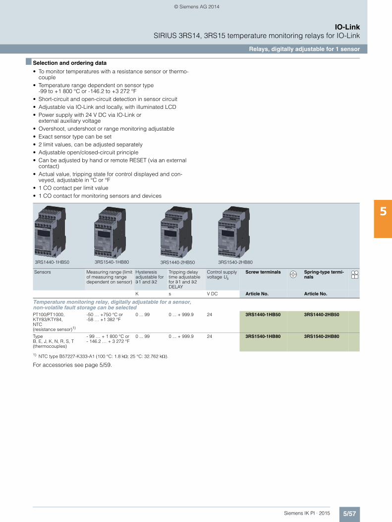
5/57Siemens IK PI · 2015
IO-LinkSIRIUS 3RS14, 3RS15 temperature monitoring relays for IO-Link
Relays, digitally adjustable for 1 sensor
5
■ Selection and ordering data
• To monitor temperatures with a resistance sensor or thermo-couple
• Temperature range dependent on sensor type -99 to +1 800 °C or -146.2 to +3 272 °F
• Short-circuit and open-circuit detection in sensor circuit• Adjustable via IO-Link and locally, with illuminated LCD• Power supply with 24 V DC via IO-Link or
external auxiliary voltage• Overshoot, undershoot or range monitoring adjustable• Exact sensor type can be set• 2 limit values, can be adjusted separately• Adjustable open/closed-circuit principle• Can be adjusted by hand or remote RESET (via an external
contact)• Actual value, tripping state for control displayed and con-
veyed, adjustable in °C or °F • 1 CO contact per limit value• 1 CO contact for monitoring sensors and devices
1) NTC type B57227-K333-A1 (100 °C: 1.8 k; 25 °C: 32.762 k).
For accessories see page 5/59.
Sensors Measuring range (limit of measuring range dependent on sensor)
Hysteresis adjustable for1 and 2
Tripping delay time adjustable for 1 and 2 DELAY
Control supply voltage Us
Screw terminals Spring-type termi-nals
K s V DC Article No. Article No.
Temperature monitoring relay, digitally adjustable for a sensor, non-volatile fault storage can be selected
PT100/PT1000, KTY83/KTY84, NTC (resistance sensor)1)
-50 … +750 °C or-58 … +1 382 °F
0 ... 99 0 ... + 999.9 24 3RS1440-1HB50 3RS1440-2HB50
Type B, E, J, K, N, R, S, T (thermocouples)
- 99 … + 1 800 °C or- 146.2 … + 3 272 °F
0 ... 99 0 ... + 999.9 24 3RS1540-1HB80 3RS1540-2HB80
3RS1440-1HB50 3RS1540-1HB80 3RS1440-2HB50 3RS1540-2HB80
IKPI_05_en.book Seite 57 Montag, 6. Oktober 2014 4:09 16
© Siemens AG 2014
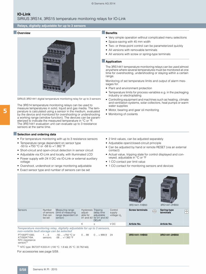
5/58 Siemens IK PI · 2015
IO-LinkSIRIUS 3RS14, 3RS15 temperature monitoring relays for IO-Link
Relays, digitally adjustable for up to 3 sensors
5
■ Overview
SIRIUS 3RS1441 digital temperature monitoring relay for up to 3 sensors
The 3RS14 temperature monitoring relays can be used to measure temperatures in solid, liquid and gas media. The tem-perature is calculated using a sensor in the medium, evaluated by the device and monitored for overshooting or undershooting a working range (window function). The devices can be param-eterized to indicate the measured temperature in °C or °F. The 3RS1441 evaluation unit can evaluate up to 3 resistance sensors at the same time.
■ Benefits
• Very simple operation without complicated menu selections• Space-saving with 45 mm width• Two- or three-point control can be parameterized quickly• All versions with removable terminals• All versions with screw or spring-type terminals
■ Application
The 3RS1441 temperature monitoring relays can be used almost anywhere where several temperatures must be monitored at one time for overshooting, undershooting or staying within a certain range.
Monitoring of set temperature limits and output of alarm mes-sages for:• Plant and environment protection• Temperature limits for process variables e.g. in the packaging
industry or electroplating• Controlling equipment and machines such as heating, climate
and ventilation systems, solar collectors, heat pumps or warm water supplies
• Motor, bearing and gear oil monitoring• Monitoring of coolants
■ Selection and ordering data
• For temperature monitoring with up to 3 resistance sensors• Temperature range dependent on sensor type
-50 to +750 °C or -58 to +1 382 °F• Short-circuit and open-circuit detection in sensor circuit• Adjustable via IO-Link and locally, with illuminated LCD• Power supply with 24 V DC via IO-Link or external auxiliary
voltage• Overshoot, undershoot or range monitoring adjustable• Exact sensor type and number of sensors can be set
• 2 limit values, can be adjusted separately• Adjustable open/closed-circuit principle• Can be adjusted by hand or remote RESET (via an external
contact)• Actual value, tripping state for control displayed and con-
veyed, adjustable in °C or °F• 1 CO contact per limit value• 1 CO contact for monitoring sensors and devices
1) NTC type: B57227-K333-A1 (100 °C: 1.8 k; 25 °C: 32.762 k).
For accessories see page 5/59.
Sensors Number of sensors that can be set
Measuring range (limit of measuring range dependent on sensor)
Hysteresis adjust-able for1 and 2
Tripping delay time adjustable for 1 and 2 DELAY
Control supply voltage Us
Screw terminals Spring-type terminals
K s V DC Article No. Article No.
Temperature monitoring relay, digitally adjustable for up to 3 sensors, non-volatile fault storage can be selectedPT100/PT1000, KTY83/KTY84, NTC (resistance sensor)1)
1 ... 3 sensors
- 50 ... +750 °C or-58 ... +1 382 °F
0 ... 99 0 ... + 999.9 24 3RS1441-1HB50 3RS1441-2HB50
3RS1441-1HB50 3RS1441-2HB50
IKPI_05_en.book Seite 58 Montag, 6. Oktober 2014 4:09 16
© Siemens AG 2014
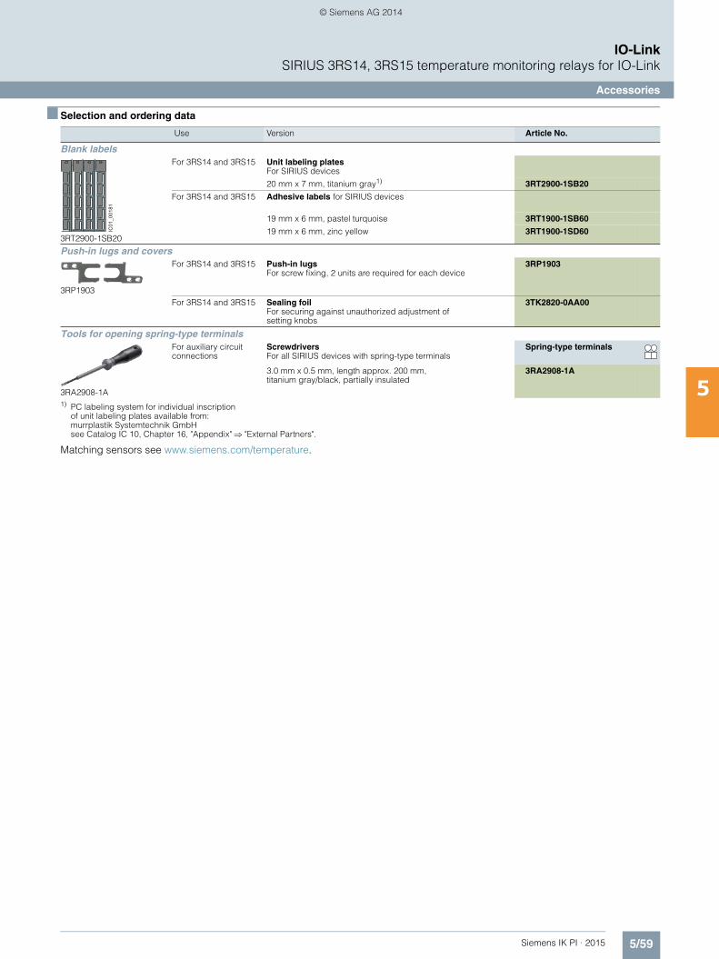
5/59Siemens IK PI · 2015
IO-LinkSIRIUS 3RS14, 3RS15 temperature monitoring relays for IO-Link
Accessories
5
■ Selection and ordering data
1) PC labeling system for individual inscriptionof unit labeling plates available from:murrplastik Systemtechnik GmbHsee Catalog IC 10, Chapter 16, "Appendix" "External Partners".
Matching sensors see www.siemens.com/temperature.
Use Version Article No.
Blank labels
3RT2900-1SB20
For 3RS14 and 3RS15 Unit labeling plates For SIRIUS devices
20 mm x 7 mm, titanium gray1) 3RT2900-1SB20
For 3RS14 and 3RS15 Adhesive labels for SIRIUS devices
19 mm x 6 mm, pastel turquoise 3RT1900-1SB60
19 mm x 6 mm, zinc yellow 3RT1900-1SD60
Push-in lugs and covers
3RP1903
For 3RS14 and 3RS15 Push-in lugs For screw fixing, 2 units are required for each device
3RP1903
For 3RS14 and 3RS15 Sealing foilFor securing against unauthorized adjustment of setting knobs
3TK2820-0AA00
Tools for opening spring-type terminals
3RA2908-1A
For auxiliary circuit connections
Screwdrivers For all SIRIUS devices with spring-type terminals
Spring-type terminals
3.0 mm x 0.5 mm, length approx. 200 mm, titanium gray/black, partially insulated
3RA2908-1A
IC01
_001
81
IKPI_05_en.book Seite 59 Montag, 6. Oktober 2014 4:09 16
© Siemens AG 2014
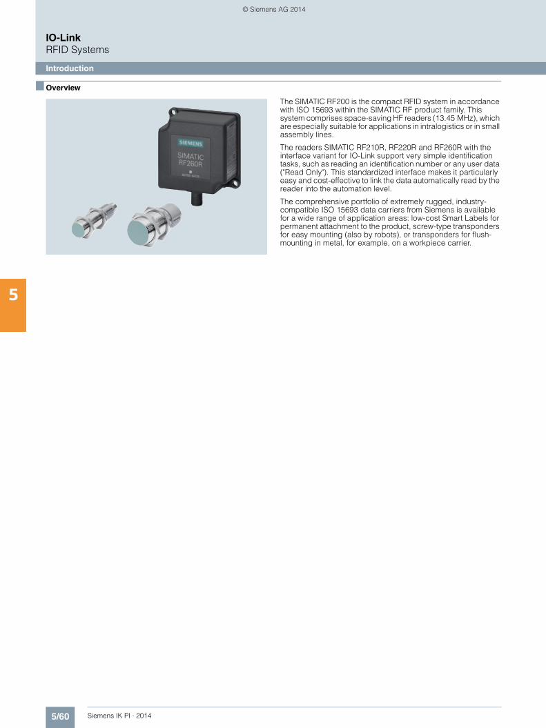
5/60 Siemens IK PI · 2014
5
IO-LinkRFID Systems
Introduction
■ Overview
The SIMATIC RF200 is the compact RFID system in accordance with ISO 15693 within the SIMATIC RF product family. This system comprises space-saving HF readers (13.45 MHz), which are especially suitable for applications in intralogistics or in small assembly lines.
The readers SIMATIC RF210R, RF220R and RF260R with the interface variant for IO-Link support very simple identification tasks, such as reading an identification number or any user data ("Read Only"). This standardized interface makes it particularly easy and cost-effective to link the data automatically read by the reader into the automation level.
The comprehensive portfolio of extremely rugged, industry-compatible ISO 15693 data carriers from Siemens is available for a wide range of application areas: low-cost Smart Labels for permanent attachment to the product, screw-type transponders for easy mounting (also by robots), or transponders for flush-mounting in metal, for example, on a workpiece carrier.
IKPI_05_en.book Seite 60 Montag, 6. Oktober 2014 4:09 16
© Siemens AG 2014
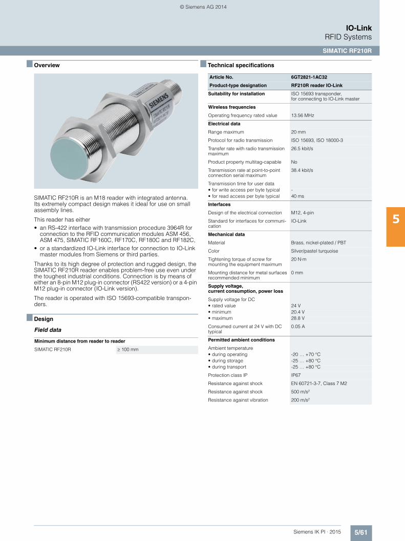
5/61Siemens IK PI · 2015
IO-LinkRFID Systems
SIMATIC RF210R
5
■ Overview
SIMATIC RF210R is an M18 reader with integrated antenna. Its extremely compact design makes it ideal for use on small assembly lines.
This reader has either• an RS-422 interface with transmission procedure 3964R for
connection to the RFID communication modules ASM 456, ASM 475, SIMATIC RF160C, RF170C, RF180C and RF182C,
• or a standardized IO-Link interface for connection to IO-Link master modules from Siemens or third parties.
Thanks to its high degree of protection and rugged design, the SIMATIC RF210R reader enables problem-free use even under the toughest industrial conditions. Connection is by means of either an 8-pin M12 plug-in connector (RS422 version) or a 4-pin M12 plug-in connector (IO-Link version).
The reader is operated with ISO 15693-compatible transpon-ders.
■ Design
Field data
■ Technical specifications
Minimum distance from reader to reader
SIMATIC RF210R 100 mm
Article No. 6GT2821-1AC32
Product-type designation RF210R reader IO-Link
Suitability for installation ISO 15693 transponder, for connecting to IO-Link master
Wireless frequencies
Operating frequency rated value 13.56 MHz
Electrical data
Range maximum 20 mm
Protocol for radio transmission ISO 15693, ISO 18000-3
Transfer rate with radio transmission maximum
26.5 kbit/s
Product property multitag-capable No
Transmission rate at point-to-point connection serial maximum
38.4 kbit/s
Transmission time for user data• for write access per byte typical -• for read access per byte typical 40 ms
Interfaces
Design of the electrical connection M12, 4-pin
Standard for interfaces for communi-cation
IO-Link
Mechanical data
Material Brass, nickel-plated / PBT
Color Silver/pastel turquoise
Tightening torque of screw for mounting the equipment maximum
20 N·m
Mounting distance for metal surfaces recommended minimum
0 mm
Supply voltage, current consumption, power loss
Supply voltage for DC• rated value 24 V• minimum 20.4 V• maximum 28.8 V
Consumed current at 24 V with DC typical
0.05 A
Permitted ambient conditions
Ambient temperature• during operating -20 … +70 °C• during storage -25 … +80 °C• during transport -25 … +80 °C
Protection class IP IP67
Resistance against shock EN 60721-3-7, Class 7 M2
Resistance against shock 500 m/s²
Resistance against vibration 200 m/s²
IKPI_05_en.book Seite 61 Montag, 6. Oktober 2014 4:09 16
© Siemens AG 2014
5/62 Siemens IK PI · 2015
■ Technical specifications (continued)
IO-LinkRFID Systems
SIMATIC RF210R
5
Design, dimensions and weight
Height 83 mm
Diameter 18 mm
Net weight 0.065 kg
Mounting type 2 x M18 nuts (included in scope of supply)
Cable length for RS 422 interface maximum
-
Cable length between master and IO-Link device maximum
20 m
Product properties, functions, components general
Type of display 3-color LED
Product feature silicon-free Yes
Standards, specifications, approvals
Verification of suitability Wireless according to R&TTE guide-lines EN300 330 and EN 301489, FCC, UL/CSA
Article No. 6GT2821-1AC32
Product-type designation RF210R reader IO-Link
■ Ordering data Article No.
■ More information
All current approvals can be found on the Internet at:
http://www.siemens.com/rfid-approvals
SIMATIC RF210R reader (IO-Link)
6GT2821-1AC32
Accessories
Note:All connection options can be found in Chapter 6 "Communication Modules".
IO-Link master
For SIMATIC ET 200eco PN, for 4 readers.
6ES7148-6JA00-0AB0
IO-Link Master 4SI
For SIMATIC ET 200S, for 4 readers.
6ES7138-4GA50-0AB0
IO-Link connecting cables• between IO-Link
master and reader, with M12 plug on the IO-Link master, open end, 4-pole, 5 m
6GT2891-4LH50
• between IO-Link master and reader, with M12 plug on the IO-Link master, open end, 4-pole, 10 m
6GT2891-4LN10
• between IO-Link master and reader, with M12 plug at both ends, 4-pole, 5 m
6GT2891-0MH50
• between IO-Link master and reader, with M12 plug at both ends, 4-pole, 10 m
6GT2891-0MN10
DVD "RFID Systems Software & Documentation"
6GT2080-2AA20
IKPI_05_en.book Seite 62 Montag, 6. Oktober 2014 4:09 16
© Siemens AG 2014

5/63Siemens IK PI · 2015
IO-LinkRFID Systems
SIMATIC RF220R
5
■ Overview
SIMATIC RF220R is an M30 reader with integrated antenna. Its compact design makes it ideal for use in small assembly lines which require a slightly higher range.
This reader has either• an RS-422 interface with transmission procedure 3964R for
connection to the RFID communication modules ASM 456, ASM 475, SIMATIC RF160C, RF170C, RF180C and RF182C,
• or a standardized IO-Link interface for connection to IO-Link master modules from Siemens or third parties.
Thanks to its high degree of protection and rugged design, the SIMATIC RF220R reader enables problem-free use even under the toughest industrial conditions. Connection is by means of either an 8-pin M12 plug-in connector (RS422 version) or a 4-pin M12 plug-in connector (IO-Link version).
The reader is operated with ISO 15693-compatible transpon-ders.
■ Design
Field data
■ Technical specifications
Minimum distance from reader to reader
SIMATIC RF220R 150 mm
Article No. 6GT2821-2AC32
Product-type designation RF220R reader IO-Link
Suitability for installation ISO 15693 transponder, for connecting to IO-Link master
Wireless frequencies
Operating frequency rated value 13.56 MHz
Electrical data
Range maximum 35 mm
Protocol for radio transmission ISO 15693, ISO 18000-3
Transfer rate with radio transmission maximum
26.5 kbit/s
Product property multitag-capable No
Transmission rate at point-to-point connection serial maximum
38.4 kbit/s
Transmission time for user data• for write access per byte typical -• for read access per byte typical 40 ms
Interfaces
Design of the electrical connection M12, 4-pin
Standard for interfaces for communication
IO-Link
Mechanical data
Material Brass, nickel-plated / PBT
Color Silver/pastel turquoise
Tightening torque of screw for mount-ing the equipment maximum
40 N·m
Mounting distance for metal surfaces recommended minimum
0 mm
Supply voltage, current consumption, power loss
Supply voltage for DC• rated value 24 V• minimum 20.4 V• maximum 28.8 V
Consumed current at 24 V with DC typical
0.05 A
Permitted ambient conditions
Ambient temperature• during operating -20 … +70 °C• during storage -25 … +80 °C• during transport -25 … +80 °C
Protection class IP IP67
Resistance against shock EN 60721-3-7, Class 7 M2
Resistance against shock 500 m/s²
Resistance against vibration 200 m/s²
IKPI_05_en.book Seite 63 Montag, 6. Oktober 2014 4:09 16
© Siemens AG 2014

5/64 Siemens IK PI · 2015
■ Technical specifications (continued)
IO-LinkRFID Systems
SIMATIC RF220R
5
Design, dimensions and weight
Height 83 mm
Diameter 30 mm
Net weight 0.14 kg
Mounting type 2 x M30 nuts (included in scope of supply)
Cable length• for RS 422 interface maximum -• between master and IO-Link device
maximum20 m
Product properties, functions, components general
Type of display 3-color LED
Product feature silicon-free Yes
Standards, specifications, approvals
Verification of suitability Wireless according to R&TTE guide-lines EN300 330 and EN 301489, FCC, UL/CSA
Article No. 6GT2821-2AC32
Product-type designation RF220R reader IO-Link
■ Ordering data Article No.
■ More information
All current approvals can be found on the Internet at:
http://www.siemens.com/rfid-approvals
SIMATIC RF220R reader (IO-Link)
6GT2821-2AC32
Accessories
Note:All connection options can be found in Chapter 6 "Communication Modules".
IO-Link master
For SIMATIC ET 200eco PN,for 4 readers.
6ES7148-6JA00-0AB0
IO-Link Master 4SI
For SIMATIC ET 200S, for 4 readers.
6ES7138-4GA50-0AB0
IO-Link connecting cables• between IO-Link
master and reader, with M12 plug on the IO-Link master, open end, 4-pole, 5 m
6GT2891-4LH50
• between IO-Link master and reader, with M12 plug on the IO-Link master, open end, 4-pole, 10 m
6GT2891-4LN10
• between IO-Link master and reader, with M12 plug at both ends, 4-pole, 5 m
6GT2891-0MH50
• between IO-Link master and reader, with M12 plug at both ends, 4-pole, 10 m
6GT2891-0MN10
DVD "RFID Systems Software & Documentation"
6GT2080-2AA20
IKPI_05_en.book Seite 64 Montag, 6. Oktober 2014 4:09 16
© Siemens AG 2014
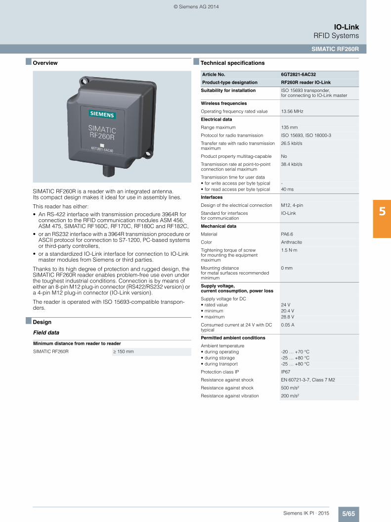
5/65Siemens IK PI · 2015
IO-LinkRFID Systems
SIMATIC RF260R
5
■ Overview
SIMATIC RF260R is a reader with an integrated antenna. Its compact design makes it ideal for use in assembly lines.
This reader has either:• An RS-422 interface with transmission procedure 3964R for
connection to the RFID communication modules ASM 456, ASM 475, SIMATIC RF160C, RF170C, RF180C and RF182C,
• or an RS232 interface with a 3964R transmission procedure or ASCII protocol for connection to S7-1200, PC-based systems or third-party controllers,
• or a standardized IO-Link interface for connection to IO-Link master modules from Siemens or third parties.
Thanks to its high degree of protection and rugged design, the SIMATIC RF260R reader enables problem-free use even under the toughest industrial conditions. Connection is by means of either an 8-pin M12 plug-in connector (RS422/RS232 version) or a 4-pin M12 plug-in connector (IO-Link version).
The reader is operated with ISO 15693-compatible transpon-ders.
■ Design
Field data
■ Technical specifications
Minimum distance from reader to reader
SIMATIC RF260R 150 mm
Article No. 6GT2821-6AC32
Product-type designation RF260R reader IO-Link
Suitability for installation ISO 15693 transponder, for connecting to IO-Link master
Wireless frequencies
Operating frequency rated value 13.56 MHz
Electrical data
Range maximum 135 mm
Protocol for radio transmission ISO 15693, ISO 18000-3
Transfer rate with radio transmission maximum
26.5 kbit/s
Product property multitag-capable No
Transmission rate at point-to-point connection serial maximum
38.4 kbit/s
Transmission time for user data• for write access per byte typical -• for read access per byte typical 40 ms
Interfaces
Design of the electrical connection M12, 4-pin
Standard for interfaces for communication
IO-Link
Mechanical data
Material PA6.6
Color Anthracite
Tightening torque of screwfor mounting the equipment maximum
1.5 N·m
Mounting distance for metal surfaces recommended minimum
0 mm
Supply voltage,current consumption, power loss
Supply voltage for DC• rated value 24 V• minimum 20.4 V• maximum 28.8 V
Consumed current at 24 V with DC typical
0.05 A
Permitted ambient conditions
Ambient temperature• during operating -20 … +70 °C• during storage -25 … +80 °C• during transport -25 … +80 °C
Protection class IP IP67
Resistance against shock EN 60721-3-7, Class 7 M2
Resistance against shock 500 m/s²
Resistance against vibration 200 m/s²
IKPI_05_en.book Seite 65 Montag, 6. Oktober 2014 4:09 16
© Siemens AG 2014
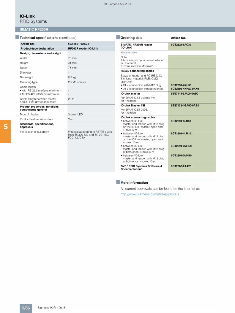
5/66 Siemens IK PI · 2015
■ Technical specifications (continued)
IO-LinkRFID Systems
SIMATIC RF260R
5
Design, dimensions and weight
Width 75 mm
Height 41 mm
Depth 75 mm
Diameter -
Net weight 0.2 kg
Mounting type 2 x M5 screws
Cable length• with RS 232 interface maximum -• for RS 422 interface maximum -
Cable length between master and IO-Link device maximum
20 m
Product properties, functions, components general
Type of display 3-color LED
Product feature silicon-free Yes
Standards, specifications,approvals
Verification of suitability Wireless according to R&TTE guide-lines EN300 330 and EN 301489, FCC, UL/CSA
Article No. 6GT2821-6AC32
Product-type designation RF260R reader IO-Link
■ Ordering data Article No.
■ More information
All current approvals can be found on the Internet at:
http://www.siemens.com/rfid-approvals
SIMATIC RF260R reader (IO-Link)
6GT2821-6AC32
Accessories
Note:All connection options can be found in Chapter 6 "Communication Modules".
RS232 connecting cables
Between reader and PC (RS232), 5 m long, material: PUR, CMG approval.• 24 V connection with M12 plug 6GT2891-4KH50• 24 V connection with open ends 6GT2891-4KH50-0AX0
IO-Link master
For SIMATIC ET 200eco PN, for 4 readers
6ES7148-6JA00-0AB0
IO-Link Master 4SI
For SIMATIC ET 200S, for 4 readers
6ES7138-4GA50-0AB0
IO-Link connecting cables• between IO-Link
master and reader, with M12 plug on the IO-Link master, open end, 4-pole, 5 m
6GT2891-4LH50
• between IO-Link master and reader, with M12 plug on the IO-Link master, open end, 4-pole, 10 m
6GT2891-4LN10
• between IO-Link master and reader, with M12 plug at both ends, 4-pole, 5 m
6GT2891-0MH50
• between IO-Link master and reader, with M12 plug at both ends, 4-pole, 10 m
6GT2891-0MN10
DVD "RFID Systems Software & Documentation"
6GT2080-2AA20
IKPI_05_en.book Seite 66 Montag, 6. Oktober 2014 4:09 16
© Siemens AG 2014