catalog d 23.1 - 2010 - nes nová dubnica s.r.o. · 2014-10-20 · pdf formats † starter...
TRANSCRIPT

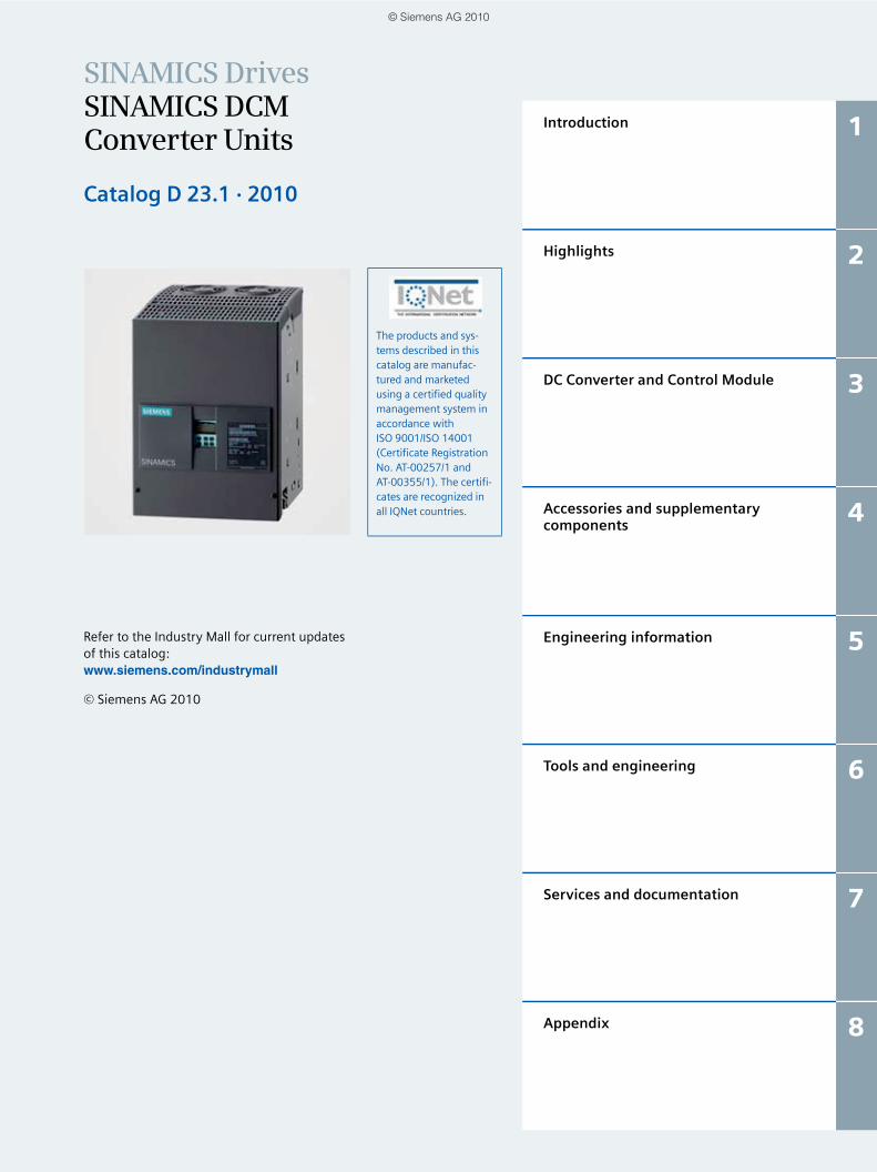
SINAMICS DCM Converter Units
Catalog D 23.1 • 2010
SINAMICS Drives
Answers for industry.
© Siemens AG 2010
SINAMICS G110, SINAMICS G120 D 11.1Standard Inverters SINAMICS G110D, SINAMICS G120DDistributed Inverters
E86060-K5511-A111-A6-7600
SINAMICS G130 D 11Drive Converter Chassis UnitsSINAMICS G150Drive Converter Cabinet Units
E86060-K5511-A101-A4-7600
SINAMICS GM150, D 12SINAMICS SM150Medium-Voltage Converters
E86060-K5512-A101-A2-7600
SINAMICS S120 D 21.3Chassis Format Units and Cabinet ModulesSINAMICS S150Converter Cabinet UnitsE86060-K5521-A131-A2-7600
SIMOREG DC-MASTER DA 21.1Digital Chassis Converters
E86060-K5321-A111-A2-7600
DC motors DA 12Sizes 160 to 63031.5 kW to 1610 kW
E86060-K5312-A101-A2-7600
DC motors DA 12 TEngineering information for Catalog DA 12
E86060-T5312-A101-A2-7600
Motion Control PM 21SIMOTION, SINAMICS S120 and Motors for Production Machines
E86060-K4921-A101-A1-7600News: E86060-K4921-E101-A1-7600
SINAMICS S110 PM 22The Basic Positioning Drive
E86060-K4922-A101-A1-7600
DVD-ROM included with Catalog D 23.1 · 2010
SITRAIN ITCTraining for Automation and Industrial SolutionsLanguage: German
E86060-K6850-A101-B9
Interactive Catalog CA 01Products for Automation and Drives
E86060-D4001-A510-C8-7600
Industry MallInformation and ordering platform in the Internet:www.siemens.com/industrymall
On the DVD-ROM included with Catalog D 23.1 · 2010, you will find:• Manuals, SINAMICS DCM and
SICROWBAR AC/DC• GSD files• Function block diagrams in the VSD format• Dimension drawings of the DC Converter
and Control Module in the DXF and PDF formats
• STARTER commissioning tool• Spare parts list in the XLS format• Catalog D 23.1 · 2010 in the PDF format• Information about service and support
Related catalogs
© Siemens AG 2010
SINAMICS DrivesSINAMICS DCM Converter Units
Catalog D 23.1 · 2010
Refer to the Industry Mall for current updates of this catalog:www.siemens.com/industrymall
© Siemens AG 2010
The products and sys-tems described in this catalog are manufac-tured and marketed using a certified quality management system in accordance with ISO 9001/ISO 14001 (Certificate Registration No. AT-00257/1 and AT-00355/1). The certifi-cates are recognized in all IQNet countries.
Introduction 1
Highlights 2
DC Converter and Control Module 3
Accessories and supplementary components
4
Engineering information 5
Tools and engineering 6
Services and documentation 7
Appendix 8
© Siemens AG 2010

0/2 Siemens D 23.1 · 2010
© Siemens AG 2010

0/3Siemens D 23.1 · 2010
Answers for industry.
Siemens Industry answers the challenges in the
manufacturing and the process industry as well as in
the building automation business. Our drive and automation
solutions based on Totally Integrated Automation (TIA) and
Totally Integrated Power (TIP) are employed in all kinds
of industry. In the manufacturing and the process industry.
In industrial as well as in functional buildings.
Siemens offers automation, drive, and low-voltage switching technology as well as industrial software from stan-dard products up to entire industry solu-tions. The industry software enables our industry customers to optimize the en-tire value chain – from product design and development through manufacture and sales up to after-sales service. Our electrical and mechanical components offer integrated technologies for the en-tire drive train – from couplings to gear units, from motors to control and drive solutions for all engineering industries. Our technology platform TIP offers ro-bust solutions for power distribution.
The high quality of our products sets industry-wide benchmarks. High environmental aims are part of our eco-management, and we imple-ment these aims consistently. Right from product design, possible effects on the environment are examined. Hence many of our products and systems are RoHS compliant (Restriction of Hazard-ous Substances). As a matter of course, our production sites are certified ac-cording to DIN EN ISO 14001, but to us, environmental protection also means most efficient utilization of valuable resources. The best example are our energy-efficient drives with energy sav-ings up to 60 %.
Check out the opportunities our automation and drive solutions provide. And discover how you can sustainably enhance your competitive edge with us.
© Siemens AG 2010

0/4 Siemens D 23.1 · 2010
Field Level
Control Level
Operations Level
Management Level
ERP – Enterprise Resource Planning
MES – Manufacturing Execution Systems
SIMATIC PCS 7Process Control (DCS)
• Maintenance• Modernization and Upgrade• Energy Management
Industrial Software for• Design and Engineering• Installation and Commissioning• Operation
Process Instrumentation SIMATIC Sensors
SINUMERIK Computer Numeric Control
SIMOTIONMotion Control System
IO-Link
HART
PROFIBUS PA
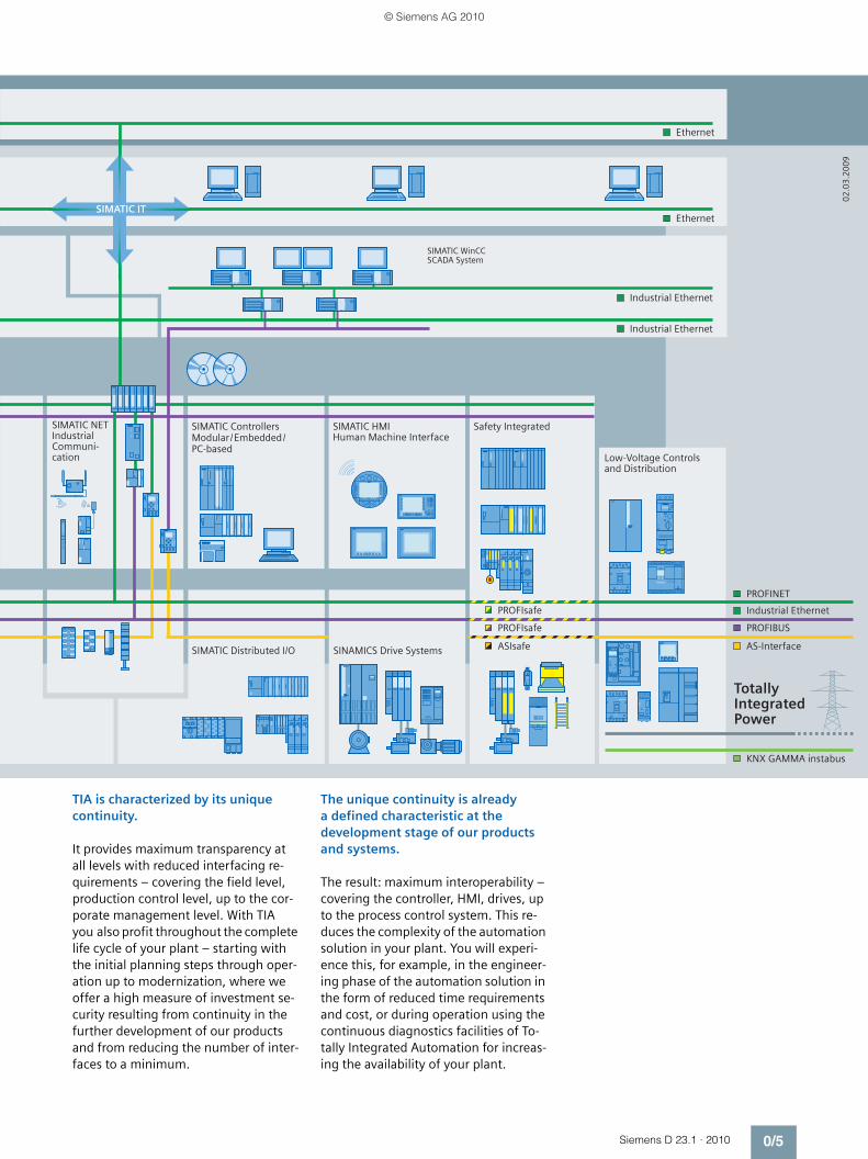
Totally IntegratedAutomation
Setting standards in productivity and competitiveness.Totally Integrated Automation.
Thanks to Totally Integrated Automation, Siemens is the only provider
of an integrated basis for implementation of customized automation
solutions – in all industries from inbound to outbound.
© Siemens AG 2010
0/5Siemens D 23.1 · 2010
SIMATIC WinCC SCADA System
SIMATIC NETIndustrial Communi-cation
SIMATIC ControllersModular/Embedded/PC-based
SIMATIC HMIHuman Machine Interface
Safety Integrated
Low-Voltage Controlsand Distribution
SIMATIC Distributed I/O SINAMICS Drive Systems
KNX GAMMA instabus
PROFIBUSPROFIsafe
PROFIsafe Industrial Ethernet
PROFINET
AS-Interface
Industrial Ethernet
Ethernet
Industrial Ethernet
Ethernet
Totally Integrated Power
ASIsafe
SIMATIC IT
02
.03
.20
09
TIA is characterized by its unique continuity.
It provides maximum transparency at all levels with reduced interfacing re-quirements – covering the field level, production control level, up to the cor-porate management level. With TIA you also profit throughout the complete life cycle of your plant – starting with the initial planning steps through oper-ation up to modernization, where we offer a high measure of investment se-curity resulting from continuity in the further development of our products and from reducing the number of inter-faces to a minimum.
The unique continuity is already a defined characteristic at the development stage of our products and systems.
The result: maximum interoperability – covering the controller, HMI, drives, up to the process control system. This re-duces the complexity of the automation solution in your plant. You will experi-ence this, for example, in the engineer-ing phase of the automation solution in the form of reduced time requirements and cost, or during operation using the continuous diagnostics facilities of To-tally Integrated Automation for increas-ing the availability of your plant.
© Siemens AG 2010
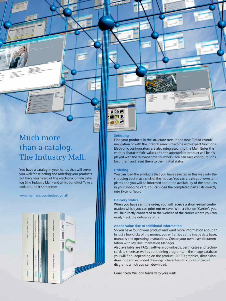
SelectingFind your products in the structure tree, in the new “Bread-crumb” navigation or with the integral search machine with expert functions. Electronic configurators are also integrated into the Mall. Enter the various characteristic values and the appropriate product will be dis-played with the relevant order numbers. You can save configurations, load them and reset them to their initial status.
OrderingYou can load the products that you have selected in this way into the shopping basket at a click of the mouse. You can create your own tem-plates and you will be informed about the availability of the products in your shopping cart. You can load the completed parts lists directly into Excel or Word.
Delivery statusWhen you have sent the order, you will receive a short e-mail confir-mation which you can print out or save. With a click on "Carrier", you will be directly connected to the website of the carrier where you can easily track the delivery status.
Added value due to additional informationSo you have found your product and want more information about it? In just a few clicks of the mouse, you will arrive at the image data base, manuals and operating instructions. Create your own user documen-tation with My Documentation Manager.Also available are FAQs, software downloads, certificates and techni-cal data sheets as well as our training programs. In the image database you will find, depending on the product, 2D/3D graphics, dimension drawings and exploded drawings, characteristic curves or circuit diagrams which you can download.
Convinced? We look forward to your visit!
Much more than a catalog.The Industry Mall.
You have a catalog in your hands that will serve you well for selecting and ordering your products. But have you heard of the electronic online cata-log (the Industry Mall) and all its benefits? Take a look around it sometime:
www.siemens.com/industrymall
© Siemens AG 2010

Siemens D 23.1 · 2010
11/2 The SINAMICS drive family1/2 Area of application1/2 Variants1/2 Platform concept and
Totally Integrated Automation1/3 Quality according to DIN EN ISO 9001
1/6 The members of the SINAMICS drive family
1/6 SINAMICS DC converters1/6 • SINAMICS DCM1/7 SINAMICS low-voltage converters1/7 • SINAMICS G1101/7 • SINAMICS G1201/7 • SINAMICS G110D1/7 • SINAMICS G120D1/8 • SINAMICS G130, SINAMICS G1501/8 • SINAMICS S1101/8 • SINAMICS S1201/8 • SINAMICS S1501/9 SINAMICS medium-voltage converters1/9 • SINAMICS GM1501/9 • SINAMICS SM1501/9 • SINAMICS GL1501/9 • SINAMICS SL150
1/10 SINAMICS DCM series of converters
1/10 Overview
1/11 The system components of a DC drive
1/11 Overview1/12 Configuration
Introduction
© Siemens AG 2010

SINAMICS DCMIntroduction
The SINAMICS drive family
1/2 Siemens D 23.1 · 2010
1
SINAMICS range applications
Area of application
SINAMICS is the new family of drives from Siemens designed for mechanical and plant engineering applications. SINAMICS offers solutions for all drive tasks:7 Simple pump and fan applications in the process industry7 Complex single drives in centrifuges, presses, extruders,
elevators, as well as conveyor and transport systems7 Drive line-ups in textile, plastic film, and paper machines, as
well as in rolling mill plants7 Highly dynamic servo drives for machine tools, as well as
packaging and printing machines
Variants
Depending on the application, the SINAMICS range offers the ideal variant for any drive task.7 SINAMICS G is designed for standard applications with induc-
tion motors. These applications have less stringent require-ments regarding the dynamic performance of the motor speed.
7 SINAMICS S handles complex drive tasks with synchro-nous/induction motors and fulfills stringent requirements regarding - the dynamic performance and accuracy- the integration of extensive technological functions in the
drive control system7 SINAMICS DC MASTER is the DC drive belonging to the
SINAMICS family. As a result of its standard expandability, it fulfills both basic as well as demanding requirements relating to drive technology and complementary markets.
Platform concept and Totally Integrated Automation
All SINAMICS versions are based on a platform concept. Com-mon hardware and software components, as well as standard-ized tools for design, configuration and commissioning tasks, ensure high-level integration across all components. SINAMICS handles a wide variety of drive tasks without system gaps. The different SINAMICS versions can be easily combined with each other.
SINAMICS is a part of the Siemens “Totally Integrated Automa-tion” concept. Integrated SINAMICS systems covering engi-neering, data management and communication at the automa-tion level, result in extremely cost-effective solutions based on SIMOTION, SINUMERIK and SIMATIC control systems.
SINAMICS G SINAMICS SSINAMICS DCM
Mixer/mills
Extrusion
Textiles
Pumps/fans/ compressors
Conveyor systems Woodworking Printing and paper
machines
Metal formingtechnology
Rolling mills
Packaging
Machine tools
G_D
211_
EN
_001
37
© Siemens AG 2010

SINAMICS DCMIntroduction
The SINAMICS drive family
1/3Siemens D 23.1 · 2010
1
SINAMICS as part of the Siemens modular automation system
Quality according to DIN EN ISO 9001
SINAMICS is able to meet the highest requirements in terms of quality. Comprehensive quality assurance measures in all devel-opment and production processes ensure a consistently high level of quality.
Of course, our quality assurance system is certified by an inde-pendent authority in accordance with DIN EN ISO 9001.
SIMATICSIMOTION SINUMERIK
SINAMICS
Asynchronous (induction) motorsSynchronous motors
G_D
211_
EN
_002
02
DC motors
© Siemens AG 2010
SINAMICS DCMIntroduction
The SINAMICS drive family
1/4 Siemens D 23.1 · 2010
1
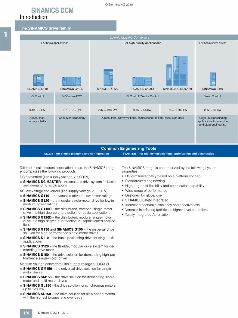
Tailored to suit different application areas, the SINAMICS range encompasses the following products:
DC converters (line supply voltage < 1 000 V)7 SINAMICS DC MASTER – the scalable drive system for basic
and demanding applications
AC low-voltage converters (line supply voltage < 1 000 V)7 SINAMICS G110 – the versatile drive for low power ratings7 SINAMICS G120 – the modular single-motor drive for low to
medium power ratings7 SINAMICS G110D – the distributed, compact single-motor
drive in a high degree of protection for basic applications7 SINAMICS G120D – the distributed, modular single-motor
drive in a high degree of protection for sophisticated applica-tions
7 SINAMICS G130 and SINAMICS G150 – the universal drive solution for high-performance single-motor drives
7 SINAMICS S110 – the basic positioning drive for single-axis applications
7 SINAMICS S120 – the flexible, modular drive system for de-manding drive tasks
7 SINAMICS S150 – the drive solution for demanding high-per-formance single-motor drives
Medium-voltage converters (line supply voltage > 1 000 V)7 SINAMICS GM150 – the universal drive solution for single-
motor drives7 SINAMICS SM150 – the drive solution for demanding single-
motor and multi-motor drives7 SINAMICS GL150 – the drive solution for synchronous motors
up to 120 MW7 SINAMICS SL150 – the drive solution for slow speed motors
with the highest torques and overloads
The SINAMICS range is characterized by the following system properties:• Uniform functionality based on a platform concept• Standardized engineering• High degree of flexibility and combination capability• Wide range of performance• Designed for global use• SINAMICS Safety Integrated• Increased economic efficiency and effectiveness • Versatile interfacing facilities to higher-level controllers• Totally Integrated Automation
V/f Control V/f Control/FCC
0.12 ... 3 kW
Pumps, fans, conveyor belts
Conveyor technology
SIZER – for simple planning and configuration STARTER – for fast commissioning, optimization and diagnosticsCommon Engineering Tools
0.12 ... 90 kW
Servo Control
Single-axis positioningapplications for machine
and plant engineering
For basic applications
Low-Voltage AC Converters
For basic servo drives
V/f Control / Vector Control
0.37 ... 250 kW 0.75 ... 7.5 kW0.75 ... 7.5 kW 75 ... 1 500 kW
For high-quality applications
Pumps, fans, conveyor belts, compressors, mixers, mills, extruders
SINAMICS S110SINAMICS G110 SINAMICS G110D SINAMICS G130/G150SINAMICS G120 SINAMICS G120D
© Siemens AG 2010

SINAMICS DCMIntroduction
The SINAMICS drive family
1/5Siemens D 23.1 · 2010
1
Motion Control applications in production machines(packaging, textile, printing, paper, plastic),
machine tools, plants and process lines
Common Engineering ToolsSIZER – for simple planning and configuration STARTER – for fast commissioning, optimization and diagnostics
V/f Control / Vector Control / Servo Control
0.12 ... 4 500 kW 75 ... 1 200 kW
Test stands, cross cutters,centrifuges
V/f Control / Vector Control
Pumps, fans, compressors, mixers, extruders, mills, rolling mills,
mining hoist drives, excavators, test stands
0.8 ... 120 MW
For high-power applications
Low-Voltage AC Converters
For demanding applications
Medium-Voltage AC Converters
Rolling mills, cross cutters and shears, wire-drawing machines,
extruders and kneaders, presses, elevator and crane installations,
cableways and lifts, mining hoists, test stand drives
DC Converters
For basic and demanding applications
6 kW ... 30 MW
Closed-loop speed control / torque control
G_D
023_
EN
_000
68
SINAMICS GM150/SM150/GL150/SL150SINAMICS S120 SINAMICS S150 SINAMICS DCM
© Siemens AG 2010

SINAMICS DCMIntroduction
The members of the SINAMICS drive family
1/6 Siemens D 23.1 · 2010
1
SINAMICS DC converters
SINAMICS DCM
The scalable drive system for basic and demanding applications
Main applications
• Machines and plants in the industrial environment (steel/aluminum, plastics, printing, paper, cranes, mining, oil and gas, excitation equip-ment) in the new plant and retrofit businesses
Application examples
• Rolling mills• Cross cutters and shears• Wire-drawing machines• Extruders and kneaders • Presses• Elevators and cranes• Cableways and lifts• Mine hoists• Test stand drives
Highlights
• PROFIBUS as standard, PROFINET optional• Variance of the Control Units• Field power supply in line with requirements• Electronics power supply for connection to 24 V DC• Power section isolated with respect to ground• Free function blocks and Drive Control Chart• Expandable functionality using SINAMICS components• Single-phase connection possible• Coated PCBs and nickel-plated copper busbars• Wide temperature range
Catalog D 23.1
© Siemens AG 2010

SINAMICS DCMIntroduction
The members of the SINAMICS drive family
1/7Siemens D 23.1 · 2010
1
SINAMICS low-voltage converters
SINAMICS G110 SINAMICS G120 SINAMICS G110D SINAMICS G120D
The versatile drive for low power ratings
The modular single-motor drive for low to medium power ratings
The distributed, compact single-motor drive in a high degree of protection for basic applications
The distributed, modular single-motor drive in a high degree of protection for sophisticated applications
Main applications
• Machines and plants for industrial and commercial applications
• Machines and plants for industrial and commercial applications (ma-chinery construction, automobile, textiles, chemical industry, print-ing, steel)
• Horizontal conveyor applications in the industrial environment, with the main focus on distribution and logistics in airports; generally suit-able for basic conveyor-related tasks with local control or connect-ed to a bus via AS-Interface
• Conveyor drive applications in in-dustrial environments, main focus on the automotive industry; also suitable for high-performance ap-plications e.g. at airports and in the food, beverage and tobacco industry (without tenside)
Application examples
• Pumps and fans• Auxiliary drives• Conveyor systems• Billboards• Door/gate operating mechanisms• Centrifuges
• Pumps and fans• Compressors• Conveyor systems
• Conveyor systems• Airports• Distribution logistics
• Conveyor systems• Electric monorail system in distri-
bution logistics
Highlights
• Compact• Can be flexibly adapted to differ-
ent applications• Simple and fast commissioning• Clear terminal layout• Optimum interaction with SIMATIC
and LOGO!
• Modular• Can be flexibly expanded• Simple and fast commissioning• Regenerative feedback• Innovative cooling concept• Optimum interaction with
SIMOTION and SIMATIC• SINAMICS Safety Integrated
• Low profile design with standard drilling dimensions (standard foot-print) in IP65 degree of protection
• Simple and fast commissioning• Versions with and without a main-
tenance switch• Optional key-operated switch• AS-Interface with bus parameter-
ization• Quick stop function• Integrated brake control,
180 V DC• Optimum interaction with SIMATIC
and LOGO!
• Low profile design with standard drilling dimensions (standard foot-print) in IP65 degree of protection
• Modular• Can be flexibly expanded• Simple and fast commissioning• Regenerative feedback• Optimum interaction with
SIMOTION and SIMATIC• SINAMICS Safety Integrated
Catalog D 11.1 Catalog D 11.1 Catalog D 11.1 Catalog D 11.1
© Siemens AG 2010
SINAMICS DCMIntroduction
The members of the SINAMICS drive family
1/8 Siemens D 23.1 · 2010
1
SINAMICS low-voltage converters
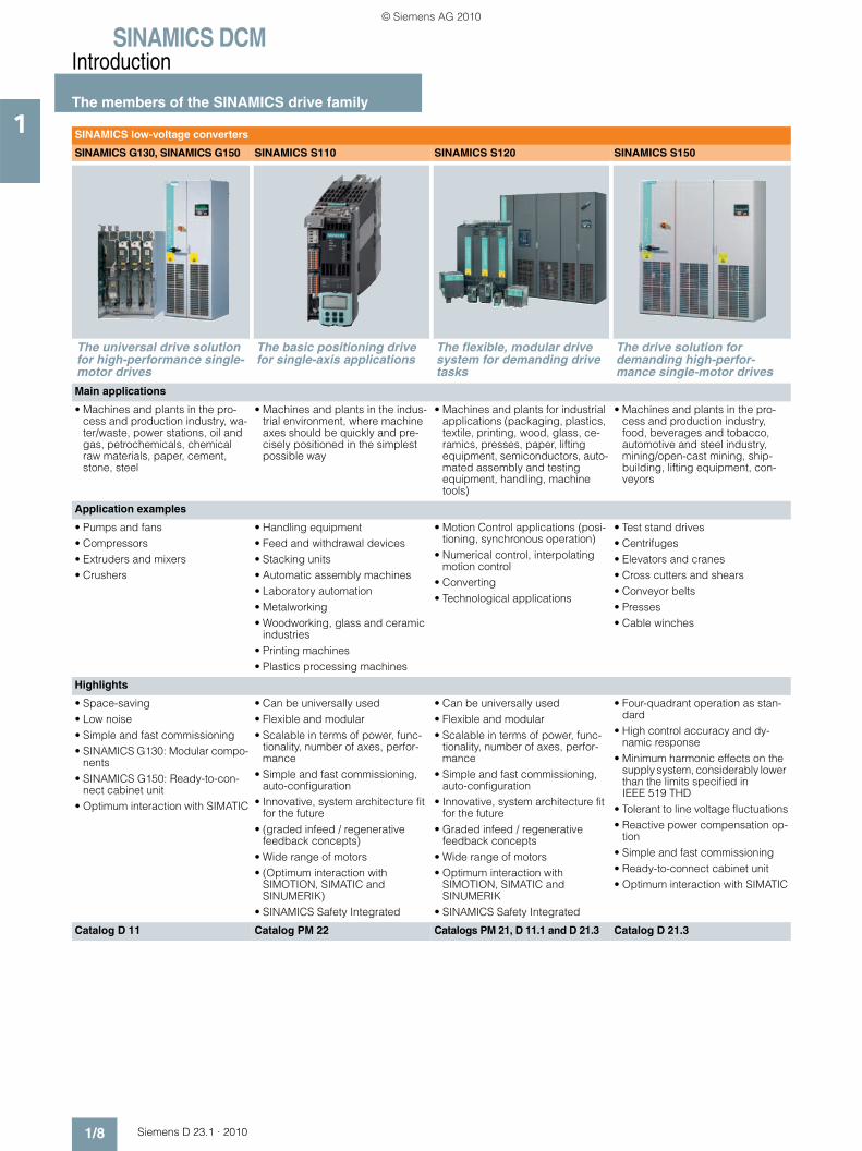
SINAMICS G130, SINAMICS G150 SINAMICS S110 SINAMICS S120 SINAMICS S150
The universal drive solution for high-performance single-motor drives
The basic positioning drive for single-axis applications
The flexible, modular drive system for demanding drive tasks
The drive solution for demanding high-perfor-mance single-motor drives
Main applications
• Machines and plants in the pro-cess and production industry, wa-ter/waste, power stations, oil and gas, petrochemicals, chemical raw materials, paper, cement, stone, steel
• Machines and plants in the indus-trial environment, where machine axes should be quickly and pre-cisely positioned in the simplest possible way
• Machines and plants for industrial applications (packaging, plastics, textile, printing, wood, glass, ce-ramics, presses, paper, lifting equipment, semiconductors, auto-mated assembly and testing equipment, handling, machine tools)
• Machines and plants in the pro-cess and production industry, food, beverages and tobacco, automotive and steel industry, mining/open-cast mining, ship-building, lifting equipment, con-veyors
Application examples
• Pumps and fans• Compressors• Extruders and mixers• Crushers
• Handling equipment• Feed and withdrawal devices• Stacking units• Automatic assembly machines• Laboratory automation• Metalworking• Woodworking, glass and ceramic
industries• Printing machines• Plastics processing machines
• Motion Control applications (posi-tioning, synchronous operation)
• Numerical control, interpolating motion control
• Converting• Technological applications
• Test stand drives• Centrifuges• Elevators and cranes• Cross cutters and shears• Conveyor belts• Presses• Cable winches
Highlights
• Space-saving• Low noise• Simple and fast commissioning• SINAMICS G130: Modular compo-
nents• SINAMICS G150: Ready-to-con-
nect cabinet unit• Optimum interaction with SIMATIC
• Can be universally used• Flexible and modular• Scalable in terms of power, func-
tionality, number of axes, perfor-mance
• Simple and fast commissioning, auto-configuration
• Innovative, system architecture fit for the future
• (graded infeed / regenerative feedback concepts)
• Wide range of motors• (Optimum interaction with
SIMOTION, SIMATIC and SINUMERIK)
• SINAMICS Safety Integrated
• Can be universally used• Flexible and modular• Scalable in terms of power, func-
tionality, number of axes, perfor-mance
• Simple and fast commissioning, auto-configuration
• Innovative, system architecture fit for the future
• Graded infeed / regenerative feedback concepts
• Wide range of motors• Optimum interaction with
SIMOTION, SIMATIC and SINUMERIK
• SINAMICS Safety Integrated
• Four-quadrant operation as stan-dard
• High control accuracy and dy-namic response
• Minimum harmonic effects on the supply system, considerably lower than the limits specified in IEEE 519 THD
• Tolerant to line voltage fluctuations• Reactive power compensation op-
tion• Simple and fast commissioning• Ready-to-connect cabinet unit• Optimum interaction with SIMATIC
Catalog D 11 Catalog PM 22 Catalogs PM 21, D 11.1 and D 21.3 Catalog D 21.3
© Siemens AG 2010

SINAMICS DCMIntroduction
The members of the SINAMICS drive family
1/9Siemens D 23.1 · 2010
1
SINAMICS medium-voltage converters
SINAMICS GM150 SINAMICS SM150 SINAMICS GL150 SINAMICS SL150
The universal drive solution for single-motor drives
The drive solution for demanding single-motor and multi-motor drives
The drive solution for synchronous motors up to 120 MW
The drive solution for slow speed motors with the high-est torques and overloads
Main applications
• Machines and plants in the process industry
• Machines and plants in the steel industry sector (rolling mills) and mining industry
• Machines and plants in the pro-cess industry, especially in the oil, gas and petrochemicals sectors
• Machines and plants in the basic materials industry, especially in the steel and mining sectors
Application examples
• Pumps and fans• Compressors• Extruders and mixers• Crushers• Marine drives
• Hot and cold rolling mill stands• Mining hoists• Test stand drives• Ore conveyor belts
• Compressors• Pumps and fans• Extruders and kneaders• Marine drives
• Blast furnace blowers
• Hot rolling mill roughing stands• Mine hoists• Ore and cement mills• Excavators
Highlights
• Space-saving• Simple and fast commissioning• Ready-to-connect cabinet unit• Optimum interaction with SIMATIC
• Four-quadrant operation as standard
• High degree of efficiency and op-eration that reduces the stress on the motor
• High control accuracy and dynamic response
• Almost no line harmonics• Reactive power compensation
option• Simple and fast commissioning• Ready-to-connect cabinet unit• Optimum interaction with SIMATIC
• Compact design and high power density
• Simple operator control and monitoring
• Extremely rugged, reliable in operation and almost mainte-nance-free
• Two directions of rotation by reversing the rotating field
• Can be seamlessly integrated into higher-level automation systems
• Low output frequency/motor speed
• High short-time overload capability
• Four-quadrant operation as standard
• Extremely rugged, reliable in operation and almost mainte-nance-free
• High efficiency• Can be seamlessly integrated into
higher-level automation systems
Catalog D 12 Catalog D 12 – –
© Siemens AG 2010
SINAMICS DCMIntroduction
SINAMICS DCM series of converters
1/10 Siemens D 23.1 · 2010
1 ■ Overview
SINAMICS DC MASTER is the new generation of DC converters from Siemens. The name SINAMICS DC MASTER – briefly: SINAMICS DCM – embodies the strengths of this new genera-tion. It combines the advantages of its predecessor SIMOREG DC-MASTER, with the advantages of the SINAMICS family.
When it comes to quality, reliability and functionality, SINAMICS DC MASTER is not only on par with its predecessor – but espe-cially in the area of functionality – offers new features and in-cludes useful functions from its predecessor as standard.
SINAMICS DC MASTER is the new member of the SINAMICS family that now makes many of the SINAMICS tools and compo-nents known from AC technology available to DC technology.
As scalable drive system, the SINAMICS DC MASTER series of converters is convincing both for basic as well as demanding applications. The DC Converter is equipped with a standard Control Unit (Standard CUD) for standard closed-loop control. The option of combining Standard CUD and Advanced CUD is used to address applications demanding a higher computa-tional performance and more interfaces.
The DC Converter of the SINAMICS DC MASTER series com-bines the open-loop and closed-loop control and power sections in one device. It especially sets itself apart as a result of the com-pact, space-saving design.
The AOP30 Advanced Operator Panel and the BOP20 Basic Operator Panel can be used for commissioning and local oper-ation.
The interfaces of the CUD and the number of digital inputs and outputs can be supplemented using additional modules – such as the TM15 and TM31 Terminal Modules.
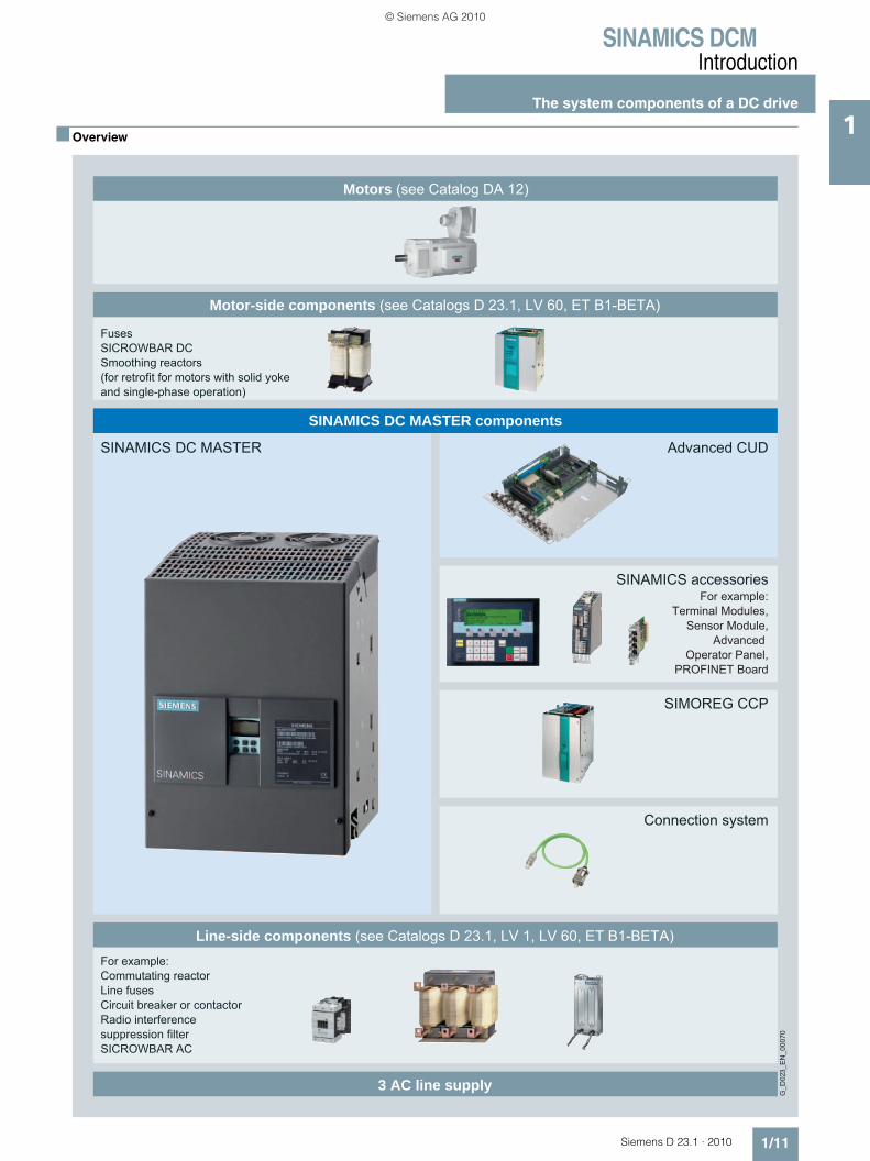
The components of a DC drive system and how these are logically interlinked are shown in the following diagram. A flow diagram on pages 1/12 and 1/13 provides support when select-ing and dimensioning the required components.
© Siemens AG 2010
SINAMICS DCMIntroduction
The system components of a DC drive
1/11Siemens D 23.1 · 2010
1■ Overview
SIMOREG CCP
Advanced CUDSINAMICS DC MASTER
For example:Terminal Modules,
Sensor Module,Advanced
Operator Panel,PROFINET Board
SINAMICS accessories
Motors (see Catalog DA 12)
Line-side components (see Catalogs D 23.1, LV 1, LV 60, ET B1-BETA)
3 AC line supply
Motor-side components (see Catalogs D 23.1, LV 60, ET B1-BETA)
SINAMICS DC MASTER components
G_D
023_
EN
_000
70
For example:Commutating reactorLine fusesCircuit breaker or contactorRadio interference suppression filterSICROWBAR AC
FusesSICROWBAR DCSmoothing reactors (for retrofit for motors with solid yoke and single-phase operation)
Connection system
© Siemens AG 2010

SINAMICS DCMIntroduction
The system components of a DC drive
1/12 Siemens D 23.1 · 2010
1 ■ Configuration
For the specific arrangementof the components, see
"Notes for EMC- compliant drive installation"
Semiconductor fuses and commutating reactor for the field circuitFuses, circuit-breaker, contactors for the DC Converter fanFuses, circuit-breaker, contactors for the electronics power supplyFuses, circuit-breaker, contactors for the DC motor fanControl transformer, if required, with fuses, circuit-breakerRadio interference suppression filter for the field circuit and electronics power supplyApplication-specific components
Additional components to be selected depending on the requirements
Dimension the motor cable and tachometer cable
Lineconnection
Observe the max. permissible short-circuit current, when required, use fuses
or short-circuit current limiting
circuit-breakers
For four-quadrant operation and rated DC current ≤ 850 A, use
semiconductor fuses in the DC motor circuit
Motor connectionLine connection
Contactor and main switch - Page 4/19Circuit-breaker - Page 4/19
Radio interference suppression filter - Page 4/19
Commutating reactor - Page 4/16
Contactor orcircuit-breaker?
Semiconductorfuses in the
DC Converter? Yes
Yes
Yes
Yes
No
No
No
No
Radio interference suppression filter?
Converter transformer
Additional loads connected to this converter
transformer?
Rated input voltage = Line voltage?
Use semiconductor fuses - Page 4/12
Motorconnection
© Siemens AG 2010

SINAMICS DCMIntroduction
The system components of a DC drive
1/13Siemens D 23.1 · 2010
1■ Configuration (continued)
1)
Configuration start
Configuration end
Motor selection according to therequirements of the driven machine
or data of an existing motor
Determine the DC Converter according to the power data
Pages 3/30 and 3/31
Extended computational performance
DC Converter and/or additional options?
Selected according to the table
DC armature currentDC armature voltage
Duty cycleTwo-quadrant or four-quadrant
operationField current and voltage
Select the rated input voltage
Open-loop &
closed-loop control
Powercom-ponents
Electrical and
mechanicaloptions
Select the options with the order codes from the option list,
Page 3/32
Select theoptions
Standard CUD
No
Yes Extended
Lefthandslot
Righthandslot FunctionalityVersion
12
3
4
Standard CUDAdvanced CUD
Advanced CUD
Advanced CUD
Standard CUD
Advanced CUD
Basic functions/PROFIBUSBasic functions+ PROFINET with accessory CBE20+ additional inp./outp. with accessory TM31, TM15+ DRIVE-CLiQAs for version 2+ Expansion of the computational performanceAs for twice version 2+ Expansion of the computational performance
Page 3/35Page 3/35
Page 3/35
Page 3/35
Description
DC Converter with options
DC ConverterData according to the Catalog
Catalog LV 1
Catalog LV 60 and Catalog D 23.1 and/or SIZER
Catalog ET B1 Beta and Catalog D 23.1 and/or SIZER
Catalog D 23.1 and/or SIZER
Catalog DA 12 (Page 3/2) and/or SIZER
Directive for selecting the rated input voltage:a) Voltage is given (e.g. modernization/retrofit)b) The secondary voltage of the converter transformer can be freely selected corresponding to the requirements of the load or the selected motor (take into account the rated supply voltagesof the converter that are available)
G_D
023_
EN
_000
59a
1)
http://www.siemens.com/dt-configurator
© Siemens AG 2010

SINAMICS DCMIntroduction
Notes
1/14 Siemens D 23.1 · 2010
1
© Siemens AG 2010

Siemens D 23.1 · 2010
22/2 Overview2/2 • The SINAMICS drive family2/2 • PROFIBUS as standard,
PROFINET optional2/2 • Variance of the Control Units2/2 • Field power supply in line with
requirements2/3 • 24 V DC electronics power supply2/3 • Power section isolated with respect to
ground2/3 • Free function blocks and
Drive Control Chart2/3 • Expandable functionality using
SINAMICS components2/3 • Single-phase connection is possible2/4 • Coated PCBs and nickel-plated
copper busbars2/4 • Wide temperature range
Highlights
© Siemens AG 2010
SINAMICS DCMHighlights
2/2 Siemens D 23.1 · 2010
2
■ Overview
SINAMICS DC MASTER is the drive system for basic applica-tions and demanding DC applications. The use in a wide range of different sectors and complementary markets demands a high degree of scalability and the ability to expand the converter series over a wide range.
In order to be able to guarantee this versatile use, SINAMICS DC MASTER has a whole raft of new features:
The SINAMICS drive family
SINAMICS DC MASTER is a member of the SINAMICS drive family. The individual SINAMICS versions are based on a com-mon platform, especially in the area of interfaces, tools and operator control & monitoring. All of the SINAMICS drives support the TIA philosophy and share common ways of engineering, communication and data man-agement with the SIMATIC, SIMOTION and SINUMERIK automa-tion systems from Siemens. When using these systems, automa-tion solutions can be very simply generated using SINAMICS.As a result of the standard and seamless integration into the automation environment of Siemens, customers also profit from faster engineering and commissioning of the complete machine automation and drive technology. Further, training-related costs are reduced and support, service & maintenance and spare parts stocking are simplified.
PROFIBUS as standard, PROFINET optional
The units are equipped as standard with PROFIBUS – the indus-try standard. PROFINET is available as option. Communication to other fieldbus systems can be realized using external adapt-ers.
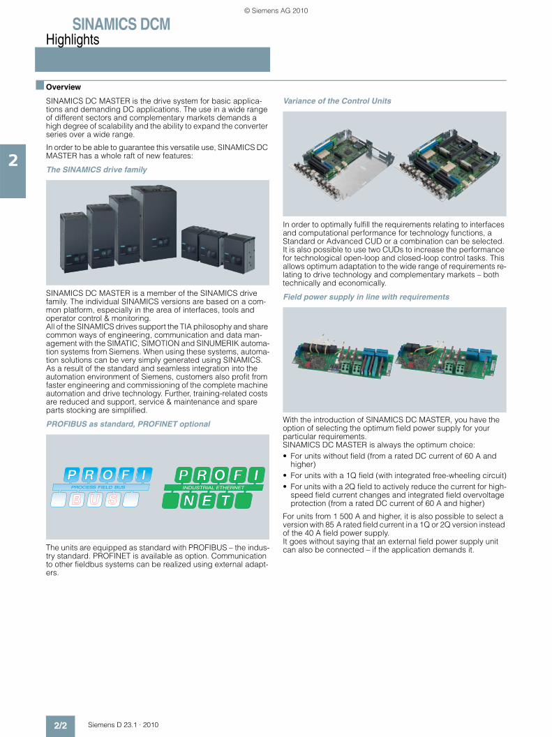
Variance of the Control Units
In order to optimally fulfill the requirements relating to interfaces and computational performance for technology functions, a Standard or Advanced CUD or a combination can be selected. It is also possible to use two CUDs to increase the performance for technological open-loop and closed-loop control tasks. This allows optimum adaptation to the wide range of requirements re-lating to drive technology and complementary markets – both technically and economically.
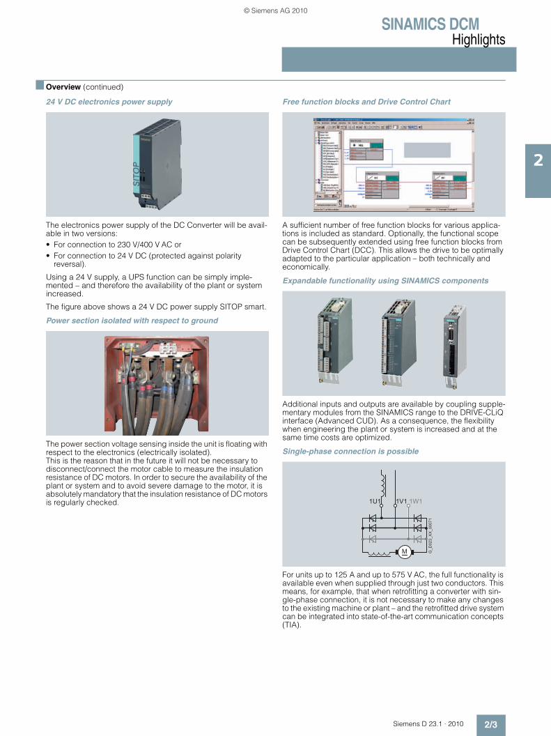
Field power supply in line with requirements
With the introduction of SINAMICS DC MASTER, you have the option of selecting the optimum field power supply for your particular requirements. SINAMICS DC MASTER is always the optimum choice:• For units without field (from a rated DC current of 60 A and
higher)• For units with a 1Q field (with integrated free-wheeling circuit)• For units with a 2Q field to actively reduce the current for high-
speed field current changes and integrated field overvoltage protection (from a rated DC current of 60 A and higher)
For units from 1 500 A and higher, it is also possible to select a version with 85 A rated field current in a 1Q or 2Q version instead of the 40 A field power supply. It goes without saying that an external field power supply unit can also be connected – if the application demands it.
© Siemens AG 2010
SINAMICS DCMHighlights
2/3Siemens D 23.1 · 2010
2
■ Overview (continued)
24 V DC electronics power supply
The electronics power supply of the DC Converter will be avail-able in two versions: • For connection to 230 V/400 V AC or • For connection to 24 V DC (protected against polarity
reversal).
Using a 24 V supply, a UPS function can be simply imple-mented – and therefore the availability of the plant or system increased.
The figure above shows a 24 V DC power supply SITOP smart.
Power section isolated with respect to ground
The power section voltage sensing inside the unit is floating with respect to the electronics (electrically isolated). This is the reason that in the future it will not be necessary to disconnect/connect the motor cable to measure the insulation resistance of DC motors. In order to secure the availability of the plant or system and to avoid severe damage to the motor, it is absolutely mandatory that the insulation resistance of DC motors is regularly checked.
Free function blocks and Drive Control Chart
A sufficient number of free function blocks for various applica-tions is included as standard. Optionally, the functional scope can be subsequently extended using free function blocks from Drive Control Chart (DCC). This allows the drive to be optimally adapted to the particular application – both technically and economically.
Expandable functionality using SINAMICS components
Additional inputs and outputs are available by coupling supple-mentary modules from the SINAMICS range to the DRIVE-CLiQ interface (Advanced CUD). As a consequence, the flexibility when engineering the plant or system is increased and at the same time costs are optimized.
Single-phase connection is possible
For units up to 125 A and up to 575 V AC, the full functionality is available even when supplied through just two conductors. This means, for example, that when retrofitting a converter with sin-gle-phase connection, it is not necessary to make any changes to the existing machine or plant – and the retrofitted drive system can be integrated into state-of-the-art communication concepts (TIA).
M G_D
023_
XX
_000
71
1U1 1V1 1W1
© Siemens AG 2010
SINAMICS DCMHighlights
2/4 Siemens D 23.1 · 2010
2
■ Overview (continued)
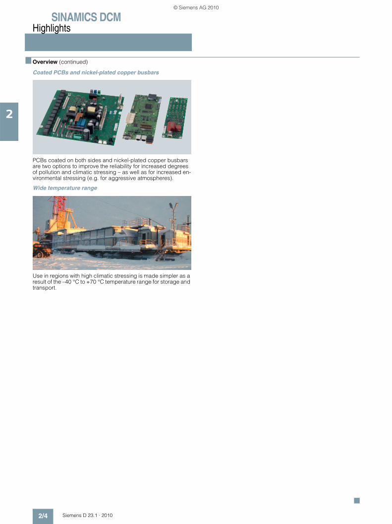
Coated PCBs and nickel-plated copper busbars
PCBs coated on both sides and nickel-plated copper busbars are two options to improve the reliability for increased degrees of pollution and climatic stressing – as well as for increased en-vironmental stressing (e.g. for aggressive atmospheres).
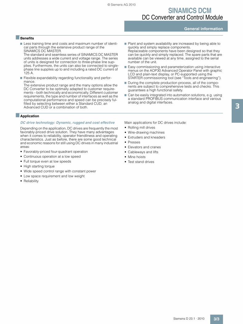
Wide temperature range
Use in regions with high climatic stressing is made simpler as a result of the –40 °C to +70 °C temperature range for storage and transport.
© Siemens AG 2010

Siemens D 23.1 · 2010
33/2 General information3/2 Overview3/3 Benefits3/3 Application3/4 Function3/4 • Functions of the closed-loop control in
the armature circuit3/6 • Functions of the closed-loop control in
the field circuit3/6 • Communication between drive
components3/8 • Single-phase operation3/8 • Coolant temperature and installation
altitude3/9 More information3/9 • Documentation
3/10 DC Converter3/10 Overview3/10 Technical specifications3/11 • General technical data3/12 • SINAMICS DC MASTER converters
for:3/12 - 400 V 3 AC, 60 to 280 A,
two-quadrant operation3/13 - 400 V 3 AC, 400 to 1 200 A,
two-quadrant operation3/14 - 400 V 3 AC, 1 600 to 3 000 A,
two-quadrant operation3/15 - 480 V 3 AC, 60 to 280 A,
two-quadrant operation3/16 - 480 V 3 AC, 450 to 1 200 A,
two-quadrant operation3/17 - 575 V 3 AC, 60 to 800 A,
two-quadrant operation3/18 - 575 V 3 AC, 1 100 to 2 800 A,
two-quadrant operation3/19 - 690 V 3 AC, 720 to 2 600 A,
two-quadrant operation3/20 - 830 V 3 AC, 950 to 1 900 A and
950 V 3 AC, 2 200 A, two-quadrant operation
3/21 - 400 V 3 AC, 15 to 125 A, four-quadrant operation
3/22 - 400 V 3 AC, 210 to 850 A, four-quadrant operation
3/23 - 400 V 3 AC, 1 200 to 3 000 A, four-quadrant operation
3/24 - 480 V 3 AC, 15 to 210 A, four-quadrant operation
3/25 - 480 V 3 AC, 280 to 1 200 A, four-quadrant operation
3/26 - 575 V 3 AC, 60 to 850 A, four-quadrant operation
3/27 - 575 V 3 AC, 1 100 to 2 800 A, four-quadrant operation
3/28 - 690 V 3 AC, 760 to 2 600 A, four-quadrant operation
3/29 - 830 V 3 AC, 950 to 1 900 A and 950 V 3 AC, 2 200 A, four-quadrant operation
3/30 Selection and ordering data3/30 • DC Converters for two-quadrant
operation3/31 • DC Converters for four-quadrant
operation3/32 Options3/32 • Available options3/33 • Option selection matrix3/34 • Ordering examples3/35 • Description of options3/37 Schematics3/37 • Control Units3/38 • DC Converters3/39 • Assignment of terminals and
connectors3/44 More information3/44 • Free function blocks3/45 • Drive Control Chart (DCC)3/45 • Power section and cooling3/45 • Parameterizing devices3/46 • Closed-loop control and open-loop
drive control3/47 • Optimization run3/47 • Monitoring and diagnostics3/48 • Functions of the inputs and outputs3/49 • Safety shutdown (E-STOP)3/49 • Serial interfaces3/49 • Control terminal block3/50 • Interface to the motor3/50 • Siemens DC motors
3/51 Control Module3/51 Application3/51 Design3/52 Technical specifications3/52 Selection and ordering data3/52 Options3/53 Accessories3/54 Schematics
DC Converter and Control Module
© Siemens AG 2010

SINAMICS DCMDC Converter and Control Module
General information
3/2 Siemens D 23.1 · 2010
3
■ Overview
SINAMICS DC MASTER converter
The SINAMICS DC MASTER series of converters includes the DC Converter and Control Module product versions.
The DC Converter includes built-in units for connection to a three-phase supply. These are used to supply the armature and field of variable-speed DC drives. The rated DC current range of the units extends from 15 to 3 000 A and can be increased by connecting DC Converters in parallel.
Depending on the application, there are units for two-quadrant and four-quadrant operation. The units are autonomous as a re-sult of the integrated parameterization device and do not require any additional equipment for parameterization. All functions as-sociated with open-loop and closed-loop control, as well as all monitoring and auxiliary functions, are handled by a micropro-cessor system. Setpoints and actual values can either be en-tered as analog or digital values.
The SINAMICS DC MASTER Control Module is the successor of the SIMOREG CM and is mainly used to retrofit and modernize DC drives.
SINAMICS DC MASTER converters are available in the following sizes (self-ventilated up to 125 A):
Detailed dimension drawings in the PDF and DXF formats are available on the DVD-ROM supplied with this catalog and in the Internet under www.siemens.com/sinamics-dcm (information material).
G_D023_XX_00067
DC Converter Control Module
Rated DC currentA
≤ 30 ≤ 280 ≤ 600 ≤ 850 ≤ 1 200 ≤ 3 000 –
Dimensions (W × H × D)mm
268 × 385 × 221 268 × 385 × 252 268 × 625 × 275 268 × 700 × 311 268 × 785 × 435 453 × 883 × 505 271 × 388 × 253
© Siemens AG 2010
SINAMICS DCMDC Converter and Control Module
General information
3/3Siemens D 23.1 · 2010
3
■ Benefits
7 Less training time and costs and maximum number of identi-cal parts through the extensive product range of the SINAMICS DC MASTER.The standard and seamless series of SINAMICS DC MASTER units addresses a wide current and voltage range. The series of units is designed for connection to three-phase line sup-plies. Furthermore, the units can also be connected to single-phase line supplies up to and including a rated DC current of 125 A.
7 Flexible expandability regarding functionality and perfor-mance.The extensive product range and the many options allow the DC Converter to be optimally adapted to customer require-ments – both technically and economically. Different customer requirements, the type and number of interfaces as well as the computational performance and speed can be precisely ful-filled by selecting between either a Standard CUD, an Advanced CUD or a combination of both.
7 Plant and system availability are increased by being able to quickly and simply replace components. Replaceable components have been designed so that they can be quickly and simply replaced. The spare parts that are available can be viewed at any time, assigned to the serial number of the unit.
7 Easy commissioning and parameterization using interactive menus on the AOP30 Advanced Operator Panel with graphic LCD and plain-text display, or PC-supported using the STARTER commissioning tool (see “Tools and engineering”).
7 During the complete production process, all of the compo-nents are subject to comprehensive tests and checks. This guarantees a high functional safety.
7 Can be easily integrated into automation solutions, e.g. using a standard PROFIBUS communication interface and various analog and digital interfaces.
■ Application
DC drive technology: Dynamic, rugged and cost effective
Depending on the application, DC drives are frequently the most favorably-priced drive solution. They have many advantages when it comes to reliability, operator friendliness and operating characteristics. Just as before, there are some good technical and economic reasons for still using DC drives in many industrial areas:• Favorably-priced four-quadrant operation• Continuous operation at a low speed• Full torque even at low speeds• High starting torque• Wide speed control range with constant power• Low space requirement and low weight• Reliability
Main applications for DC drives include:• Rolling mill drives• Wire-drawing machines• Extruders and kneaders• Presses• Elevators and cranes• Cableways and lifts• Mine hoists• Test stand drives
© Siemens AG 2010
SINAMICS DCMDC Converter and Control Module
General information
3/4 Siemens D 23.1 · 2010
3
■ Function
Function Description
Functions of the closed-loop control in the armature circuit
Speed setpoint The source of the speed setpoint and additional setpoints can be freely selected by making the appropriate parameter settings:• Entered using analog values 0 to ± 10 V, 0 to ± 20 mA, 4 to 20 mA• Using the integrated motorized potentiometer• Using binectors with the functions: Fixed setpoint, jogging, crawl• Entered via serial interfaces of the SINAMICS DC MASTER• Entered via supplementary modulesThe scaling is realized so that 100 % setpoint (formed from the main setpoint and supplementary setpoints) corresponds to the maximum motor speed.The setpoint can be limited to a minimum and maximum value via a parameter or connector. Further, additional points are provided in the software e.g. in order to be able to enter supplementary setpoints before or after the ramp-function generator. The “setpoint enable function” can be selected using a binector. After a parameterizable filter function (PT1 element), the summed setpoint is transferred to the setpoint input of the speed controller. In this case, the ramp-function generator is also active.
Actual speed One of four sources can be selected as signal for the speed actual value.• Analog tachometer
The voltage of the tachogenerator at maximum speed can be between 8 and 270 V. Adaptation to the voltage is realized using parameters.
• Pulse encoder The pulse encoder type, the number of pulses per revolution and the maximum speed are set using parameters. Encoder signals (symmetrical: with additional inverted track, unsymmetrical: referred to ground) up to a maximum differential voltage of 27 V can be processed by the evaluation electronics.The rated voltage range (5 or 15 V) for the encoder is selected via parameter. The power supply for the pulse encoder can be taken from the DC Converter for a rated voltage of 15 V. 5 V encoders require an external power supply. The pulse encoder is evaluated across the three tracks: Track 1, track 2 and zero mark. However, pulse encoders without zero mark can also be used. A position actual value can be sensed using the zero mark. The maximum frequency of the encoder pulses can be 300 kHz. It is recommended that pulse encoders with at least 1 024 pulses per revolution are used (due to the smooth running operation at low speeds).
• Operation without tachometer with EMF controlA speed actual value encoder is not required for closed-loop EMF control. In this case, the output voltage of the device is measured in the DC Converter. The measured armature voltage is compensated by the internal voltage drop across the motor (IR compensation). The level of compensation is automatically determined during the current controller opti-mization run. The accuracy of this control method, which is defined by the temperature-dependent change in the motor armature circuit resistance, is approximately 5 %. We recommend that the current controller optimization run is repeated when the motor is in the warm operating condition to achieve a higher degree of precision. The closed-loop EMF control can be used if the requirements on the precision are not so high, if it is not possible to mount an encoder and the motor is operated in the armature voltage control range.Notice: In this mode, EMF-dependent field weakening is not possible.
• Freely selectable speed actual value signal For this mode, any connector number can be selected as speed actual value signal. This setting is especially selected if the speed actual value sensing is implemented on a supplementary technology module. Before the speed actual value is transferred to the speed controller, it can be smoothed using a parameterizable smooth-ing element (PT1 element) and two adjustable bandstop filters. Bandstop filters are used primarily for the purpose of filtering out resonant frequencies caused by mechanical resonance. The resonant frequency and the filter quality factor can be set.
Ramp-function generator
When there is a step change in the setpoint applied at its input, the ramp-function generator converts the setpoint into a signal with a steady rate of rise. Ramp-up time and ramp-down time can be selected independently of one another. In addition, the ramp-function generator has initial and final rounding-off (jerk limiting) that are effective at the beginning and end of the ramp-up time.All of the times for the ramp-function generator can be set independently of one another.Three parameter sets are available for the ramp-function generator times; these can be selected via binary select inputs or a serial interface (via binectors). The ramp-up function generator parameters can be switched over in operation. In addition, a multiplication factor can be applied to the value of parameter set 1 via a connector (to change the ramp-func-tion generator data via a connector). When entering ramp-function generator times with the value zero, the speed set-point is directly input into the speed controller.
© Siemens AG 2010

SINAMICS DCMDC Converter and Control Module
General information
3/5Siemens D 23.1 · 2010
3
■ Function (continued)
Function Description
Functions of the closed-loop control in the armature circuit (continued)
Speed controller The speed controller compares the setpoint and actual value of the speed and if there is a deviation, enters an appropri-ate current setpoint into the current controller (principle: Speed control with lower-level current controller). The speed controller is implemented as PI controller with additional D component that can be selected. Further, a switchable droop function can be parameterized. All of the controller parameters can be adjusted independently of one another. The value for Kp (gain) can be adapted depending on a connector signal (external or internal).In this case, the P gain of the speed controller can be adapted depending on the speed actual value, current actual value, setpoint-actual value distance or the wound roll diameter. This can be precontrolled in order to achieve a high dynamic performance in the speed control loop. For this purpose, e.g. depending on the friction and the moment of iner-tia of the drive, a torque setpoint signal can be added after the speed controller. The friction and moment of inertia com-pensation are determined using an automatic optimization run.The output quantity of the speed controller can be directly adjusted via parameter after the controller has been enabled.Depending on the parameterization, the speed controller can be bypassed and the converter controlled either with closed-loop torque or current control. In addition, it is also possible to switch between speed control/torque control in operation using the “leading/following switchover” selection function. The function can be selected as binector using a binary user-assignable terminal or a serial interface. The torque setpoint is input via a selectable connector and can therefore come from an analog user-assignable terminal or via a serial interface.A limiting controller is active in the following drive state (torque or current controlled operation). In this case, depending on a speed limit that can be selected using parameters, the limiting controller can intervene in order to prevent the drive accelerating in an uncontrolled fashion. In this case, the drive is limited to an adjustable speed deviation.
Torque limiting The speed controller output represents the torque setpoint or current setpoint depending on what has been parameter-ized. In torque-controlled operation, the speed controller output is weighted with the machine flux Φ and transferred to a current limiting stage as a current setpoint. Torque control is applied primarily in field weakening operation in order to limit the maximum motor torque independent of the speed.The following functions are available:• Independent setting of positive and negative torque limits using parameters.• Switchover of the torque limit using a binector as a function of a parameterizable switchover speed.• Free input of a torque limit by means of a connector signal, e.g. via an analog input or via serial interface.The lowest specified quantity should always be effective as the actual torque limit. Additional torque setpoints can be added after the torque limit.
Current limiting The current limit that can be adjusted after the torque limit is used to protect the converter and the motor. The lowest specified quantity is always effective as the actual current limit.The following current limit values can be set:• Independent setting of positive and negative current limits using parameters (maximum motor current setting).• Free input of a current limit using a connector, e.g. from an analog input or via a serial interface.• Separate setting of current limit using parameters for stopping and quick stop.• Speed-dependent current limiting: An automatically initiated, speed-dependent reduction of the current limit at high
speeds can be parameterized (commutation limit curve of the motor).I 2t monitoring of the power section: The thermal state of the thyristors is calculated for all current values. When the thyris-
tor limit temperature is reached, the unit responds as a function of parameter settings, i.e. the converter current is reduced to the rated DC current or the unit is shut down with a fault message. This function is used to protect the thyris-tors.
Current controller The current controller is implemented as PI controller with P gain and integral time that can be set independently from one another. The P and I components can also be deactivated (pure P controller or pure I controller). The current actual value is sensed using a current transformer on the three-phase side and is fed to the current controller via a load resistor and rectification after analog-digital conversion. The resolution is 10 bits for the converter related current. The current limit output is used as current setpoint.The current controller output transfers the firing angle to the gating unit – the precontrol function is effective in parallel.
Precontrol The precontrol in the current control loop improves the dynamic performance of the closed-loop control. This allows rise times of between 6 and 9 ms in the current control loop. The precontrol is effective dependent on the current setpoint and EMF of the motor and ensures – for intermittent and continuous current or when the torque direction is reversed – that the required firing angle is quickly transferred as setpoint to the gating unit.
Auto-reversing module In conjunction with the current control loop, the auto-reversing module (only for units with four-quadrant drives) ensures the logical sequence of all of the operations and processes required to change the torque direction. The torque direction can also be disabled when required via parameter.
Gating unit The gating unit generates the firing pulses for the power section thyristors in synchronism with the line supply voltage. The synchronization is independent of the speed and the electronics supply and is sensed at the power section. The tim-ing of the firing pulses is defined by the output values of the current controller and the precontrol. The firing angle limit can be set using parameters.In a frequency range from 45 to 65 Hz, the gating unit automatically adapts itself to the actual line frequency.
© Siemens AG 2010

SINAMICS DCMDC Converter and Control Module
General information
3/6 Siemens D 23.1 · 2010
3
■ Function (continued)
Function Description
Functions of the closed-loop control in the field circuit
EMF controller The EMF controller compares setpoint and actual value of the EMF (induced motor voltage) and enters the setpoint for the field current controller. This therefore permits field weakening control that is dependent on the EMF. The EMF controller operates as PI controller; P and I components can be adjusted independently of one another and/or the controller can be operated as pure P controller or pure I controller. A precontrol function operates in parallel to the EMF controller. Depending on the speed, it precontrols the field current setpoint using an automatically recorded field characteristic (refer to the optimization runs). There is an adding point after the EMF controller, where the supplementary field current setpoints can be entered either via a connector, via an analog input or a serial interface. The limit is then effective for the field current setpoint. In this case, the field current setpoint can be limited to a minimum and a maximum value that can be set independently from one another. The limit is realized using a parameter or a connector. The mini-mum for the upper limit or the maximum for the lower limit is effective.
Field current controller The field current controller is a PI controller – where Kp and Tn can be independently set. It can also be operated as pure P and I controller. A precontrol function operates in parallel to the field current controller. This calculates and sets the fir-ing angle for the field circuit as a function of current setpoint and line supply voltage. The precontrol supports the current controller and ensures that the field circuit has the appropriate dynamic performance.
Gating unit The gating unit generates the firing pulses for the power section thyristors in synchronism with the line supply voltage in the field circuit. The synchronization is detected in the power section and is therefore independent of the electronics power supply. The timing of the firing pulses is defined by the output values of the current controller and the precontrol. The firing angle limit can be set using parameters. In a frequency range from 45 to 65 Hz, the gating unit automatically adapts itself to the actual line supply voltage.
Communication between drive components
DRIVE-CLiQ Communication between SINAMICS components is realized using the standard internal SINAMICS interface DRIVE-CLiQ (this is an abbreviation for Drive Component Link with IQ). This couples the Control Unit with the connected drive components (e.g. DC Converter, Terminal Modules etc.). DRIVE-CLiQ provides standard digital interfaces for all SINAMICS drives. This permits modularization of the drive func-tions and thus increased flexibility for customized solutions (allows power and intelligence to be separated).The DRIVE-CLiQ hardware is based on the Industrial Ethernet standard and uses twisted-pair cables. The DRIVE-CLiQ line provides the transmit and receive signals and also the 24 V power supply.Setpoints and actual values, control commands, status feedback signals and electronic rating plate data of the drive components are transferred via DRIVE-CLiQ. Only original Siemens cables must be used for DRIVE-CLiQ cables. As a result of the special transfer and damping properties, only these cables can guarantee that the system functions per-fectly.
SINAMICS Link SINAMICS Link allows data to be directly exchanged between several (2 to 64) Control Units. A higher-level master is not required. The following Control Units support SINAMICS Link:• CU320-2• Advanced CUDFor use of SINAMICS Link, all of the Control Units must be equipped with the CBE20 Communication Board (option G20).In addition, a memory card (options S01, S02) is required for the Advanced CUD. Communication can either be synchronous (only CU320-2) or non-synchronous or a combination of both. Each participant can send and receive up to 16 process data words. For instance, SINAMICS Link can be used for the following applications:• Torque distribution for n drives• Setpoint cascading for n drives• Load distribution of drives coupled through a material web• Master/slave function for infeed units• Couplings between SINAMICS units
© Siemens AG 2010
SINAMICS DCMDC Converter and Control Module
General information
3/7Siemens D 23.1 · 2010
3
■ Function (continued)
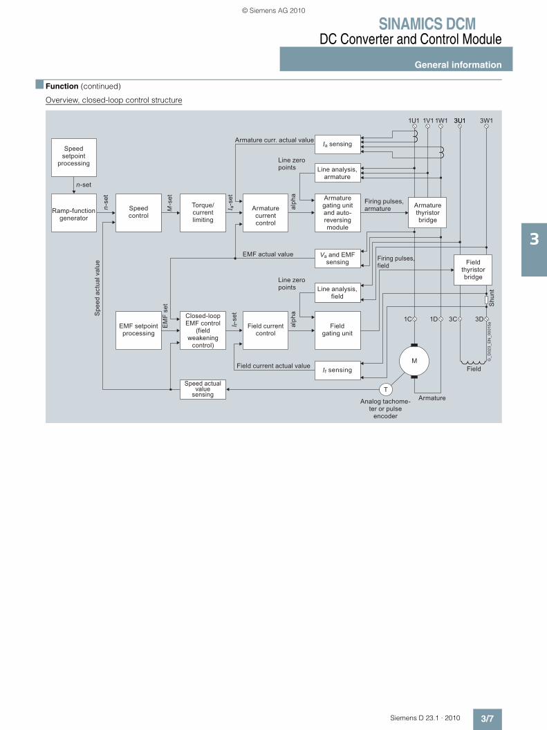
Overview, closed-loop control structure
Speedsetpoint
processing
Speedcontrol
EMF setpointprocessing
Closed-loop EMF control
(field weakening
control)
Speed actual value
sensing
Field currentcontrol
Armature currentcontrol
Line analysis,armature
Line analysis,field
Fieldgating unit
If sensing
Va and EMF sensing
EMF actual value
Ia sensing
1U1 1V1 1W1 3W13U13U1
Armaturethyristorbridge
Fieldthyristorbridge
Field
Armature
M
T
Firing pulses, armature
Firing pulses, field
Armature gating unitand auto-reversingmodule
Armature curr. actual value
Line zeropoints
Line zeropoints
Field current actual value
Torque/currentlimiting
Ramp-function generator
n-set
n-se
t
M-s
et
I a-s
etI f-
set
alph
aal
pha
Shu
ntG
_D02
3_E
N_0
0015
a
1C 1D 3C 3D
Analog tachome-ter or pulse
encoder
EM
F se
t
Spe
ed a
ctua
l val
ue
© Siemens AG 2010
SINAMICS DCMDC Converter and Control Module
General information
3/8 Siemens D 23.1 · 2010
3
■ Function (continued)
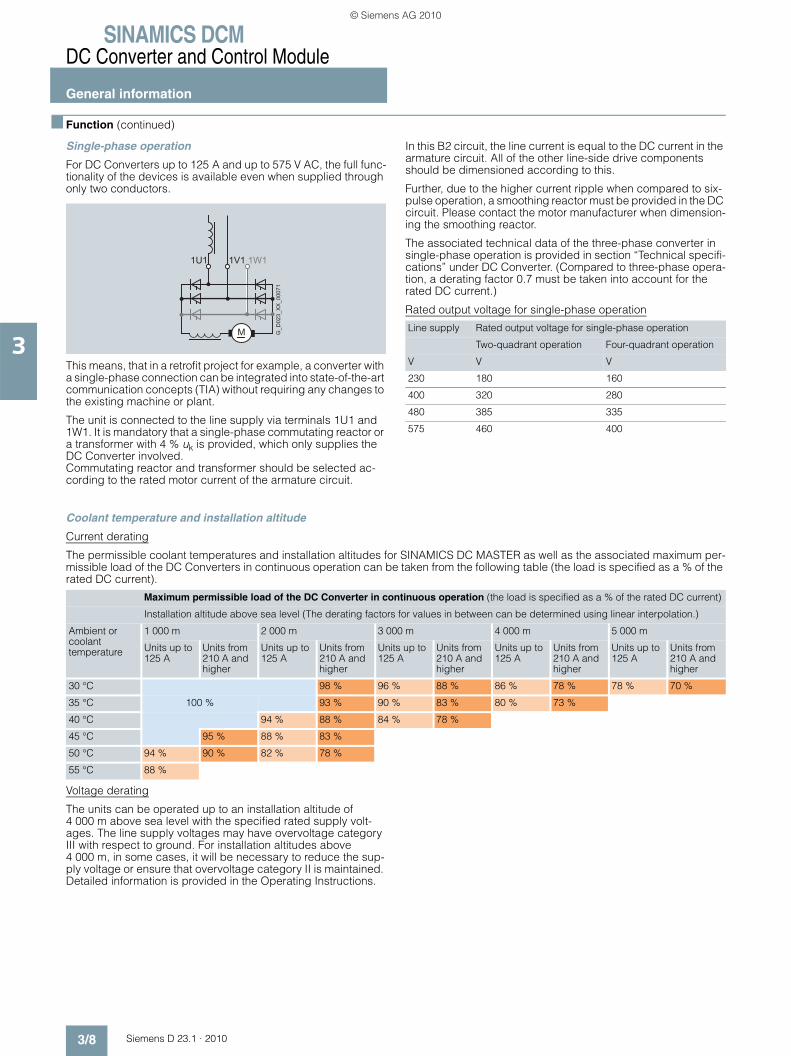
Single-phase operation
For DC Converters up to 125 A and up to 575 V AC, the full func-tionality of the devices is available even when supplied through only two conductors.
This means, that in a retrofit project for example, a converter with a single-phase connection can be integrated into state-of-the-art communication concepts (TIA) without requiring any changes to the existing machine or plant.
The unit is connected to the line supply via terminals 1U1 and 1W1. It is mandatory that a single-phase commutating reactor or a transformer with 4 % uk is provided, which only supplies the DC Converter involved. Commutating reactor and transformer should be selected ac-cording to the rated motor current of the armature circuit.
In this B2 circuit, the line current is equal to the DC current in the armature circuit. All of the other line-side drive components should be dimensioned according to this.
Further, due to the higher current ripple when compared to six-pulse operation, a smoothing reactor must be provided in the DC circuit. Please contact the motor manufacturer when dimension-ing the smoothing reactor.
The associated technical data of the three-phase converter in single-phase operation is provided in section “Technical specifi-cations” under DC Converter. (Compared to three-phase opera-tion, a derating factor 0.7 must be taken into account for the rated DC current.)
Rated output voltage for single-phase operation
Coolant temperature and installation altitude
Current derating
The permissible coolant temperatures and installation altitudes for SINAMICS DC MASTER as well as the associated maximum per-missible load of the DC Converters in continuous operation can be taken from the following table (the load is specified as a % of the rated DC current).
Voltage derating
The units can be operated up to an installation altitude of 4 000 m above sea level with the specified rated supply volt-ages. The line supply voltages may have overvoltage category III with respect to ground. For installation altitudes above 4 000 m, in some cases, it will be necessary to reduce the sup-ply voltage or ensure that overvoltage category II is maintained. Detailed information is provided in the Operating Instructions.
M G_D
023_
XX
_000
71
1U1 1V1 1W1
Line supply Rated output voltage for single-phase operation
Two-quadrant operation Four-quadrant operation
V V V
230 180 160
400 320 280
480 385 335
575 460 400
Maximum permissible load of the DC Converter in continuous operation (the load is specified as a % of the rated DC current)
Installation altitude above sea level (The derating factors for values in between can be determined using linear interpolation.)
Ambient or coolant temperature
1 000 m 2 000 m 3 000 m 4 000 m 5 000 m
Units up to 125 A
Units from 210 A and higher
Units up to 125 A
Units from 210 A and higher
Units up to 125 A
Units from 210 A and higher
Units up to 125 A
Units from 210 A and higher
Units up to 125 A
Units from 210 A and higher
30 °C 98 % 96 % 88 % 86 % 78 % 78 % 70 %
35 °C 100 % 93 % 90 % 83 % 80 % 73 %
40 °C 94 % 88 % 84 % 78 %
45 °C 95 % 88 % 83 %
50 °C 94 % 90 % 82 % 78 %
55 °C 88 %
© Siemens AG 2010
SINAMICS DCMDC Converter and Control Module
General information
3/9Siemens D 23.1 · 2010
3
■ More information
Documentation
The technical documentation includes the following manuals:• SINAMICS DC MASTER DC Converter Operating Instructions• SINAMICS DC MASTER Control Module Operating Instructions• List Manual (parameter lists and function diagrams)• Function Manual SINAMICS Free function blocks
Documentation is provided on a DVD when the converter is sup-plied. German, English, French, Spanish, Italian and Russian are the standard languages. The documentation can be separately ordered as hard copy in the languages specified above.
The manuals include all of the data relevant to SINAMICS DC MASTER units:• Description• Technical data• Installation instructions• Commissioning guide• Maintenance information• Function diagrams• Description of faults and alarms• Parameter list • List of connectors and binectors• Dimension drawings
Documentation on DVD
The product DVD contains all of the operating instructions, both for DC Converters as well as the Control Module in electronic form as PDF files.
The DVD also includes application documents about the use and application of DC drives, on topics such as • Axial winders• 12-pulse applications• Leading-following switchover (MASTER slave operation)• SINAMICS DC MASTER as field supply unit• Engineering tips
These documents are being continually supplemented and expanded.
Additional information and ordering data for the various docu-ments are provided in the catalog section “Services and docu-mentation”.
© Siemens AG 2010
SINAMICS DCMDC Converter and Control Module
DC Converter
3/10 Siemens D 23.1 · 2010
3
■ Overview
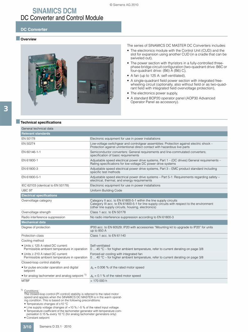
The series of SINAMICS DC MASTER DC Converters includes:• The electronics module with the Control Unit (CUD) and the
slot for expansion using another CUD (in a cradle that can be swiveled out),
• The power section with thyristors in a fully-controlled three-phase bridge circuit configuration (two-quadrant drive: B6C or four-quadrant drive: (B6) A (B6) C),
• A fan (up to 125 A: self-ventilated),• A single-quadrant field power section with integrated free-
wheeling circuit (optionally, also without field or as two-quad-rant field with integrated field overvoltage protection),
• The electronics power supply,• A standard BOP20 operator panel (AOP30 Advanced
Operator Panel as accessory).
■ Technical specifications
1) Conditions:The closed-loop control (PI control) stability is referred to the rated motor speed and applies when the SINAMICS DC MASTER is in the warm operat-ing condition. This is based on the following preconditions:• Temperature changes of ±10 °C• Line supply voltage changes of +10 % / -5 % of the rated input voltage• Temperature coefficient of the tachometer generator with temperature com-
pensation 0.15 ‰ every 10 °C (for analog tachometer generators only)• Constant setpoint
General technical data
Relevant standards
EN 50178 Electronic equipment for use in power installations
EN 50274 Low-voltage switchgear and controlgear assemblies: Protection against electric shock – Protection against unintentional direct contact with hazardous live parts
EN 60146-1-1 Semiconductor converters: General requirements and line-commutated converters; specification of basic requirements
EN 61800-1 Adjustable speed electrical power drive systems, Part 1 – (DC drives) General requirements – Rating specifications for low-voltage DC power drive systems
EN 61800-3 Adjustable speed electrical power drive systems, Part 3 – EMC product standard including specific test methods
EN 61800-5-1 Adjustable speed electrical power drive systems – Part 5-1: Requirements regarding safety – electrical, thermal, and energy requirements
IEC 62103 (identical to EN 50178) Electronic equipment for use in power installations
UBC 97 Uniform Building Code
Electrical specifications
Overvoltage category Category II acc. to EN 61800-5-1 within the line supply circuitsCategory III acc. to EN 61800-5-1 for line supply circuits with respect to the environment (other line supply circuits, housing, electronics)
Overvoltage strength Class 1 acc. to EN 50178
Radio interference suppression No radio interference suppression according to EN 61800-3
Mechanical data
Degree of protection IP00 acc. to EN 60529; IP20 with accessories “Mounting kit to upgrade to IP20” for units up to 850 A
Protection class Class 1 acc. to EN 61140
Cooling method
• Units ≤ 125 A rated DC current: Permissible ambient temperature in operation
Self-ventilated0 ... 45 °C – for higher ambient temperature, refer to current derating on page 3/8
• Units ≥ 210 A rated DC current: Permissible ambient temperature in operation
Forced-air cooling with integrated fan0 ... 40 °C – for higher ambient temperature, refer to current derating on page 3/8
Closed-loop control stability
• for pulse encoder operation and digital setpoint
Δn = 0.006 % of the rated motor speed
• for analog tachometer and analog setpoint 1) Δn = 0.1 % of the rated motor speed
MTBF > 170 000 h
© Siemens AG 2010
SINAMICS DCMDC Converter and Control Module
DC Converter
3/11Siemens D 23.1 · 2010
3
■ Technical specifications (continued)
General technical data
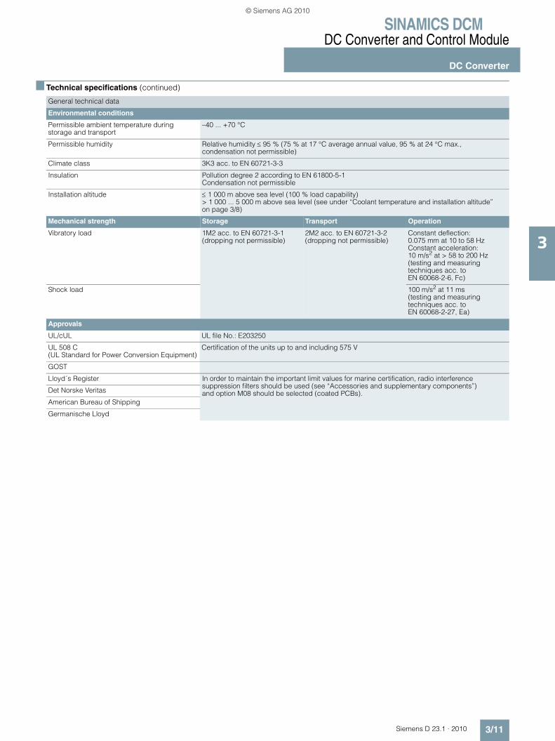
Environmental conditions
Permissible ambient temperature during storage and transport
–40 ... +70 °C
Permissible humidity Relative humidity ≤ 95 % (75 % at 17 °C average annual value, 95 % at 24 °C max., condensation not permissible)
Climate class 3K3 acc. to EN 60721-3-3
Insulation Pollution degree 2 according to EN 61800-5-1Condensation not permissible
Installation altitude ≤ 1 000 m above sea level (100 % load capability)> 1 000 ... 5 000 m above sea level (see under “Coolant temperature and installation altitude” on page 3/8)
Mechanical strength Storage Transport Operation
Vibratory load 1M2 acc. to EN 60721-3-1(dropping not permissible)
2M2 acc. to EN 60721-3-2(dropping not permissible)
Constant deflection:0.075 mm at 10 to 58 HzConstant acceleration:10 m/s2 at > 58 to 200 Hz(testing and measuring techniques acc. to EN 60068-2-6, Fc)
Shock load 100 m/s2 at 11 ms (testing and measuring techniques acc. to EN 60068-2-27, Ea)
Approvals
UL/cUL UL file No.: E203250
UL 508 C (UL Standard for Power Conversion Equipment)
Certification of the units up to and including 575 V
GOST
Lloyd´s Register In order to maintain the important limit values for marine certification, radio interference suppression filters should be used (see “Accessories and supplementary components”) and option M08 should be selected (coated PCBs).Det Norske Veritas
American Bureau of Shipping
Germanische Lloyd
© Siemens AG 2010

SINAMICS DCMDC Converter and Control Module
DC Converter
3/12 Siemens D 23.1 · 2010
3
■ Technical specifications (continued)
SINAMICS DC MASTER converters for 400 V 3 AC, 60 to 280 A, two-quadrant operation
Note: Detailed dimension drawings in the PDF and DXF formats are available on the DVD-ROM supplied with this catalog and in the Internet under www.siemens.com/sinamics-dcm (information material).
Data for single-phase operation
Type
6RA8025-6DS22-0AA0
6RA8028-6DS22-0AA0
6RA8031-6DS22-0AA0
6RA8075-6DS22-0AA0
6RA8078-6DS22-0AA0
Rated armature supply voltage 1)
V 400 V 3 AC (+15/–20 %)
Rated armature input current A 50 75 104 174 232
Rated supply voltage, electronics power supply
V 380 (–25 %) … 480 V (+10 %) 2 AC; In = 1 A or190 (–25 %) … 240 V (+10 %) 2 AC; In = 2 A
Rated fan supply voltage V Self-ventilated 24 V DC internal
Rated fan current A Internal supply
Air flow m3/h 300
Sound pressure level 2) dB (A) 52.4
Rated field supply voltage 1) V 400 V 2 AC (+15/–20 %)
Rated frequency Hz 45 … 65
Rated DC voltage 1) V 485
Rated DC current A 60 90 125 210 280
Overload capability x × In 1.8
Rated power kW 29 44 61 102 136
Power loss at rated DC current kW 0.25 0.36 0.41 0.69 0.81
Rated DC field voltage 1) V max. 325
Rated DC field current A 10 15
Normal ambient temperature in operation 3)
°C 0 … +45 0 … +40
Storage and transport temperature
°C –40 … +70
Installation altitude above sea level 3)
≤ 1 000 m for rated DC current
Dimensions
• Width mm 268
• Height mm 385
• Depth mm 252
Weight, approx. kg 10 14 15
Type
6RA8025-6DS22-0AA0
6RA8028-6DS22-0AA0
6RA8031-6DS22-0AA0
Rated DC voltage V 320
Rated DC current A 42.0 63.0 87.5
1) The armature/field supply voltage may be lower than the rated armature/field voltage (set via parameter; in the case of units with a 400 V rated voltage, an input voltage of up to 85 V is permitted). The output voltage decreases accordingly. The specified DC output voltage can be maintained up to an undervoltage of 5 % of the line supply voltage (rated armature/field supply voltage).
2) Fan noise for a unit installed in an IP20 electrical cabinet (door closed, 50 Hz operation or operation at 24 V DC for units with an internal supply).
3) Derating factors for higher temperatures and installation altitudes, see page 3/8.
© Siemens AG 2010

SINAMICS DCMDC Converter and Control Module
DC Converter
3/13Siemens D 23.1 · 2010
3
■ Technical specifications (continued)
SINAMICS DC MASTER converters for 400 V 3 AC, 400 to 1 200 A, two-quadrant operation
Note: Detailed dimension drawings in the PDF and DXF formats are available on the DVD-ROM supplied with this catalog and in the Internet under www.siemens.com/sinamics-dcm (information material).
Type
6RA8081-6DS22-0AA0
6RA8085-6DS22-0AA0
6RA8087-6DS22-0AA0
6RA8091-6DS22-0AA0
Rated armature supply voltage 1)
V 400 V 3 AC (+15/–20 %)
Rated armature input current A 332 498 706 996
Rated supply voltage, electronics power supply
V 380 (–25 %) … 480 V (+10 %) 2 AC; In = 1 A or190 (–25 %) … 240 V (+10 %) 2 AC; In = 2 A
Rated fan supply voltage V 400 V 3 AC ± 10 % (50 Hz) 460 V 3 AC ± 10 % (60 Hz)
Rated fan current A 0.23 3) 0.3 3)
Air flow m3/h 600 1 000
Sound pressure level 2) dB (A) 64.5
Rated field supply voltage 1) V 400 V 2 AC (+15/–20 %)
480 V 2 AC (+10/–20 %)
Rated frequency Hz 45 … 65
Rated DC voltage 1) V 485
Rated DC current A 400 600 850 1 200
Overload capability x × In 1.8
Rated power kW 194 291 412 582
Power loss at rated DC current kW 1.37 1.84 2.47 4.11
Rated DC field voltage 1) V max. 325 max. 390
Rated DC field current A 25 30 40
Normal ambient temperature in operation 4)
°C 0 … +40
Storage and transport temperature
°C –40 … +70
Installation altitude above sea level 4)
≤ 1 000 m for rated DC current
Dimensions
• Width mm 268
• Height mm 625 700 783
• Depth mm 275 311 435
Weight, approx. kg 26 28 38 78
1) The armature/field supply voltage may be lower than the rated armature/field voltage (set via parameter; in the case of units with a 400 V rated voltage, an input voltage of up to 85 V is permitted). The output voltage decreases accordingly. The specified DC output voltage can be maintained up to an undervoltage of 5 % of the line supply voltage (rated armature/field supply voltage).
2) Fan noise for a unit installed in an IP20 electrical cabinet (door closed, 50 Hz operation or operation at 24 V DC for units with an internal supply).
3) For fan motor type R2D220-AB02-19 in units 6RA8081, 6RA8085, and 6RA8087 with a rated voltage of 400 V or 575 V, UL systems require a Siemens motor circuit-breaker of type 3RV1011-0DA1 or 3RV1011-0EA1, set to 0.3 A.
4) Derating factors for higher temperatures and installation altitudes, see page 3/8.
© Siemens AG 2010
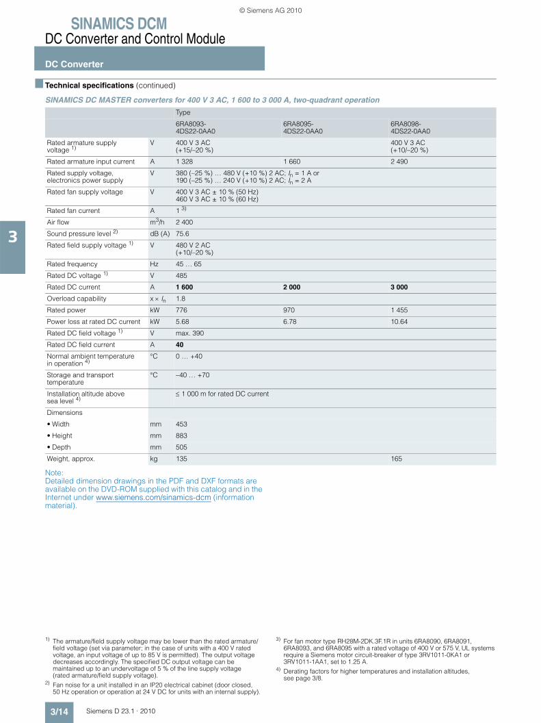
SINAMICS DCMDC Converter and Control Module
DC Converter
3/14 Siemens D 23.1 · 2010
3
■ Technical specifications (continued)
SINAMICS DC MASTER converters for 400 V 3 AC, 1 600 to 3 000 A, two-quadrant operation
Note: Detailed dimension drawings in the PDF and DXF formats are available on the DVD-ROM supplied with this catalog and in the Internet under www.siemens.com/sinamics-dcm (information material).
Type
6RA8093-4DS22-0AA0
6RA8095-4DS22-0AA0
6RA8098-4DS22-0AA0
Rated armature supply voltage 1)
V 400 V 3 AC (+15/–20 %)
400 V 3 AC (+10/–20 %)
Rated armature input current A 1 328 1 660 2 490
Rated supply voltage, electronics power supply
V 380 (–25 %) … 480 V (+10 %) 2 AC; In = 1 A or190 (–25 %) … 240 V (+10 %) 2 AC; In = 2 A
Rated fan supply voltage V 400 V 3 AC ± 10 % (50 Hz) 460 V 3 AC ± 10 % (60 Hz)
Rated fan current A 1 3)
Air flow m3/h 2 400
Sound pressure level 2) dB (A) 75.6
Rated field supply voltage 1) V 480 V 2 AC (+10/–20 %)
Rated frequency Hz 45 … 65
Rated DC voltage 1) V 485
Rated DC current A 1 600 2 000 3 000
Overload capability x × In 1.8
Rated power kW 776 970 1 455
Power loss at rated DC current kW 5.68 6.78 10.64
Rated DC field voltage 1) V max. 390
Rated DC field current A 40
Normal ambient temperature in operation 4)
°C 0 … +40
Storage and transport temperature
°C –40 … +70
Installation altitude above sea level 4)
≤ 1 000 m for rated DC current
Dimensions
• Width mm 453
• Height mm 883
• Depth mm 505
Weight, approx. kg 135 165
1) The armature/field supply voltage may be lower than the rated armature/field voltage (set via parameter; in the case of units with a 400 V rated voltage, an input voltage of up to 85 V is permitted). The output voltage decreases accordingly. The specified DC output voltage can be maintained up to an undervoltage of 5 % of the line supply voltage (rated armature/field supply voltage).
2) Fan noise for a unit installed in an IP20 electrical cabinet (door closed, 50 Hz operation or operation at 24 V DC for units with an internal supply).
3) For fan motor type RH28M-2DK.3F.1R in units 6RA8090, 6RA8091, 6RA8093, and 6RA8095 with a rated voltage of 400 V or 575 V, UL systems require a Siemens motor circuit-breaker of type 3RV1011-0KA1 or 3RV1011-1AA1, set to 1.25 A.
4) Derating factors for higher temperatures and installation altitudes, see page 3/8.
© Siemens AG 2010

SINAMICS DCMDC Converter and Control Module
DC Converter
3/15Siemens D 23.1 · 2010
3
■ Technical specifications (continued)
SINAMICS DC MASTER converters for 480 V 3 AC, 60 to 280 A, two-quadrant operation
Note: Detailed dimension drawings in the PDF and DXF formats are available on the DVD-ROM supplied with this catalog and in the Internet under www.siemens.com/sinamics-dcm (information material).
Data for single-phase operation
Type
6RA8025-6FS22-0AA0
6RA8028-6FS22-0AA0
6RA8031-6FS22-0AA0
6RA8075-6FS22-0AA0
6RA8078-6FS22-0AA0
Rated armature supply voltage 1)
V 480 V 3 AC (+10/–20 %)
Rated armature input current A 50 75 104 174 232
Rated supply voltage, electronics power supply
V 380 (–25 %) … 480 V (+10 %) 2 AC; In = 1 A or190 (–25 %) … 240 V (+10 %) 2 AC; In = 2 A
Rated fan supply voltage V Self-ventilated 24 V DC internal
Rated fan current A Internal supply
Air flow m3/h 300
Sound pressure level 2) dB (A) 52.4
Rated field supply voltage 1) V 480 V 2 AC (+10/–20 %)
Rated frequency Hz 45 … 65
Rated DC voltage 1) V 575
Rated DC current A 60 90 125 210 280
Overload capability x × In 1.8
Rated power kW 35 52 72 121 161
Power loss at rated DC current kW 0.30 0.38 0.43 0.72 0.81
Rated DC field voltage 1) V max. 390
Rated DC field current A 10 15
Normal ambient temperature in operation 3)
°C 0 … +45 0 … +40
Storage and transport temperature
°C –40 … +70
Installation altitude above sea level 3)
≤ 1 000 m for rated DC current
Dimensions
• Width mm 268
• Height mm 385
• Depth mm 252
Weight, approx. kg 11 14 15
Type
6RA8025-6FS22-0AA0
6RA8028-6FS22-0AA0
6RA8031-6FS22-0AA0
Rated DC voltage V 385
Rated DC current A 42.0 63.0 87.5
1) The armature/field supply voltage may be lower than the rated armature/field voltage (set via parameter; in the case of units with a 400 V rated voltage, an input voltage of up to 85 V is permitted). The output voltage decreases accordingly. The specified DC output voltage can be maintained up to an undervoltage of 5 % of the line supply voltage (rated armature/field supply voltage).
2) Fan noise for a unit installed in an IP20 electrical cabinet (door closed, 50 Hz operation or operation at 24 V DC for units with an internal supply).
3) Derating factors for higher temperatures and installation altitudes, see page 3/8.
© Siemens AG 2010

SINAMICS DCMDC Converter and Control Module
DC Converter
3/16 Siemens D 23.1 · 2010
3
■ Technical specifications (continued)
SINAMICS DC MASTER converters for 480 V 3 AC, 450 to 1 200 A, two-quadrant operation
Note: Detailed dimension drawings in the PDF and DXF formats are available on the DVD-ROM supplied with this catalog and in the Internet under www.siemens.com/sinamics-dcm (information material).
Type
6RA8082-6FS22-0AA0
6RA8085-6FS22-0AA0
6RA8087-6FS22-0AA0
6RA8091-6FS22-0AA0
Rated armature supply voltage 1)
V 480 V 3 AC (+10/–20 %)
Rated armature input current A 374 498 706 996
Rated supply voltage, electronics power supply
V 380 (–25 %) … 480 V (+10 %) 2 AC; In = 1 A or190 (–25 %) … 240 V (+10 %) 2 AC; In = 2 A
Rated fan supply voltage V 400 V 3 AC ± 10 % (50 Hz) 460 V 3 AC ± 10 % (60 Hz)
Rated fan current A 0.23 3) 0.3 3)
Air flow m3/h 600 1 000
Sound pressure level 2) dB (A) 64.5
Rated field supply voltage 1) V 480 V 2 AC (+10/–20 %)
Rated frequency Hz 45 … 65
Rated DC voltage 1) V 575
Rated DC current A 450 600 850 1 200
Overload capability x × In 1.8
Rated power kW 259 345 489 690
Power loss at rated DC current kW 1.58 1.91 2.60 4.24
Rated DC field voltage 1) V max. 390
Rated DC field current A 25 30
Normal ambient temperature in operation 4)
°C 0 … +40
Storage and transport temperature
°C –40 … +70
Installation altitude above sea level 4)
≤ 1 000 m for rated DC current
Dimensions
• Width mm 268
• Height mm 625 700 783
• Depth mm 275 311 435
Weight, approx. kg 28 38 78
1) The armature/field supply voltage may be lower than the rated armature/field voltage (set via parameter; in the case of units with a 400 V rated voltage, an input voltage of up to 85 V is permitted). The output voltage decreases accordingly. The specified DC output voltage can be maintained up to an undervoltage of 5 % of the line supply voltage (rated armature/field supply voltage).
2) Fan noise for a unit installed in an IP20 electrical cabinet (door closed, 50 Hz operation or operation at 24 V DC for units with an internal supply).
3) For fan motor type R2D220-AB02-19 in units 6RA8081, 6RA8085, and 6RA8087 with a rated voltage of 400 V or 575 V, UL systems require a Siemens motor circuit-breaker of type 3RV1011-0DA1 or 3RV1011-0EA1, set to 0.3 A.
4) Derating factors for higher temperatures and installation altitudes, see page 3/8.
© Siemens AG 2010

SINAMICS DCMDC Converter and Control Module
DC Converter
3/17Siemens D 23.1 · 2010
3
■ Technical specifications (continued)
SINAMICS DC MASTER converters for 575 V 3 AC, 60 to 800 A, two-quadrant operation
Note: Detailed dimension drawings in the PDF and DXF formats are available on the DVD-ROM supplied with this catalog and in the Internet under www.siemens.com/sinamics-dcm (information material).
Data for single-phase operation
Type
6RA8025-6GS22-0AA0
6RA8031-6GS22-0AA0
6RA8075-6GS22-0AA0
6RA8081-6GS22-0AA0
6RA8085-6GS22-0AA0
6RA8087-6GS22-0AA0
Rated armature supply voltage 1)
V 575 V 3 AC (+10/–20 %)
Rated armature input current A 50 104 174 332 498 664
Rated supply voltage, electronics power supply
V 380 (–25 %) … 480 V (+10 %) 2 AC; In = 1 A or190 (–25 %) … 240 V (+10 %) 2 AC; In = 2 A
Rated fan supply voltage V Self-ventilated 24 V DC internal 400 V 3 AC ± 10 % (50 Hz) 460 V 3 AC ± 10 % (60 Hz)
Rated fan current A Internal supply 0.23 3)
Air flow m3/h 300 600
Sound pressure level 2) dB (A) 52.4 64.5
Rated field supply voltage 1) V 480 V 2 AC (+10/–20 %)
Rated frequency Hz 45 … 65
Rated DC voltage 1) V 690
Rated DC current A 60 125 210 400 600 800
Overload capability x × In 1.8
Rated power kW 41 86 145 276 414 552
Power loss at rated DC current kW 0.27 0.46 0.74 1.60 2.00 2.69
Rated DC field voltage 1) V max. 390
Rated DC field current A 10 15 25 30
Normal ambient temperature in operation 4)
°C 0 … +45 0 … +40
Storage and transport temperature
°C –40 … +70
Installation altitude above sea level 4)
≤ 1 000 m for rated DC current
Dimensions
• Width mm 268
• Height mm 385 625 700
• Depth mm 252 275 311
Weight, approx. kg 11 14 26 28 38
Type
6RA8025-6GS22-0AA0
6RA8031-6GS22-0AA0
Rated DC voltage V 460
Rated DC current A 42.0 87.5
1) The armature/field supply voltage may be lower than the rated armature/field voltage (set via parameter; in the case of units with a 400 V rated voltage, an input voltage of up to 85 V is permitted). The output voltage decreases accordingly. The specified DC output voltage can be maintained up to an undervoltage of 5 % of the line supply voltage (rated armature/field supply voltage).
2) Fan noise for a unit installed in an IP20 electrical cabinet (door closed, 50 Hz operation or operation at 24 V DC for units with an internal supply).
3) For fan motor type R2D220-AB02-19 in units 6RA8081, 6RA8085, and 6RA8087 with a rated voltage of 400 V or 575 V, UL systems require a Siemens motor circuit-breaker of type 3RV1011-0DA1 or 3RV1011-0EA1, set to 0.3 A.
4) Derating factors for higher temperatures and installation altitudes, see page 3/8.
© Siemens AG 2010

SINAMICS DCMDC Converter and Control Module
DC Converter
3/18 Siemens D 23.1 · 2010
3
■ Technical specifications (continued)
SINAMICS DC MASTER converters for 575 V 3 AC, 1 100 to 2 800 A, two-quadrant operation
Note: Detailed dimension drawings in the PDF and DXF formats are available on the DVD-ROM supplied with this catalog and in the Internet under www.siemens.com/sinamics-dcm (information material).
Type
6RA8090-6GS22-0AA0
6RA8093-4GS22-0AA0
6RA8095-4GS22-0AA0
6RA8096-4GS22-0AA0
6RA8097-4GS22-0AA0
Rated armature supply voltage 1)
V 575 V 3 AC (+10/–20 %)
Rated armature input current A 913 1 328 1 660 1 826 2 324
Rated supply voltage, electronics power supply
V 380 (–25 %) … 480 V (+10 %) 2 AC; In = 1 A or190 (–25 %) … 240 V (+10 %) 2 AC; In = 2 A
Rated fan supply voltage V 400 V 3 AC ± 10 % (50 Hz) 460 V 3 AC ± 10 % (60 Hz)
Rated fan current A 0.3 3) 1 4)
Air flow m3/h 1 000 2 400
Sound pressure level 2) dB (A) 64.5 75.6
Rated field supply voltage 1) V 480 V 2 AC (+10/–20 %)
Rated frequency Hz 45 … 65
Rated DC voltage 1) V 690
Rated DC current A 1 100 1 600 2 000 2 200 2 800
Overload capability x × In 1.8
Rated power kW 759 1 104 1 380 1 518 1 932
Power loss at rated DC current kW 4.02 6.04 7.07 7.39 10.53
Rated DC field voltage 1) V max. 390
Rated DC field current A 40
Normal ambient temperature in operation 5)
°C 0 … +40
Storage and transport temperature
°C –40 … +70
Installation altitude above sea level 5)
≤ 1 000 m for rated DC current
Dimensions
• Width mm 268 453
• Height mm 785 883
• Depth mm 435 505
Weight, approx. kg 78 135 165
1) The armature/field supply voltage may be lower than the rated armature/field voltage (set via parameter; in the case of units with a 400 V rated voltage, an input voltage of up to 85 V is permitted). The output voltage decreases accordingly. The specified DC output voltage can be maintained up to an undervoltage of 5 % of the line supply voltage (rated armature/field supply voltage).
2) Fan noise for a unit installed in an IP20 electrical cabinet (door closed, 50 Hz operation or operation at 24 V DC for units with an internal supply).
3) For fan motor type R2D220-AB02-19 in units 6RA8081, 6RA8085, and 6RA8087 with a rated voltage of 400 V or 575 V, UL systems require a Siemens motor circuit-breaker of type 3RV1011-0DA1 or 3RV1011-0EA1, set to 0.3 A.
4) For fan motor type RH28M-2DK.3F.1R in units 6RA8090, 6RA8091, 6RA8093, and 6RA8095 with a rated voltage of 400 V or 575 V, UL systems require a Siemens motor circuit-breaker of type 3RV1011-0KA1 or 3RV1011-1AA1, set to 1.25 A.
5) Derating factors for higher temperatures and installation altitudes, see page 3/8.
© Siemens AG 2010

SINAMICS DCMDC Converter and Control Module
DC Converter
3/19Siemens D 23.1 · 2010
3
■ Technical specifications (continued)
SINAMICS DC MASTER converters for 690 V 3 AC, 720 to 2 600 A, two-quadrant operation
Note: Detailed dimension drawings in the PDF and DXF formats are available on the DVD-ROM supplied with this catalog and in the Internet under www.siemens.com/sinamics-dcm (information material).
Type
6RA8086-6KS22-0AA0
6RA8090-6KS22-0AA0
6RA8093-4KS22-0AA0
6RA8095-4KS22-0AA0
6RA8097-4KS22-0AA0
Rated armature supply voltage 1)
V 690 V 3 AC (+10/–20 %)
Rated armature input current A 598 830 1 245 1 660 2 158
Rated supply voltage, electronics power supply
V 380 (–25 %) … 480 V (+10 %) 2 AC; In = 1 A or190 (–25 %) … 240 V (+10 %) 2 AC; In = 2 A
Rated fan supply voltage V 400 V 3 AC ± 10 % (50 Hz) 460 V 3 AC ± 10 % (60 Hz)
Rated fan current A 0.23 3) 0.3 3) 1 4)
Air flow m3/h 600 1 000 2 400
Sound pressure level 2) dB (A) 64.5 75.6
Rated field supply voltage 1) V 480 V 2 AC (+10/–20 %)
Rated frequency Hz 45 … 65
Rated DC voltage 1) V 830
Rated DC current A 720 1 000 1 500 2 000 2 600
Overload capability x × In 1.8
Rated power kW 598 830 1 245 1 660 2 158
Power loss at rated DC current kW 2.77 3.96 6.67 8.16 10.30
Rated DC field voltage 1) V max. 390
Rated DC field current A 30 40
Normal ambient temperature in operation 5)
°C 0 … +40
Storage and transport temperature
°C –40 … +70
Installation altitude above sea level 5)
≤ 1 000 m for rated DC current
Dimensions
• Width mm 268 453
• Height mm 700 785 883
• Depth mm 311 435 505
Weight, approx. kg 38 78 135 165
1) The armature/field supply voltage may be lower than the rated armature/field voltage (set via parameter; in the case of units with a 400 V rated voltage, an input voltage of up to 85 V is permitted). The output voltage decreases accordingly. The specified DC output voltage can be maintained up to an undervoltage of 5 % of the line supply voltage (rated armature/field supply voltage).
2) Fan noise for a unit installed in an IP20 electrical cabinet (door closed, 50 Hz operation or operation at 24 V DC for units with an internal supply).
3) For fan motor type R2D220-AB02-19 in units 6RA8081, 6RA8085, and 6RA8087 with a rated voltage of 400 V or 575 V, UL systems require a Siemens motor circuit-breaker of type 3RV1011-0DA1 or 3RV1011-0EA1, set to 0.3 A.
4) For fan motor type RH28M-2DK.3F.1R in units 6RA8090, 6RA8091, 6RA8093, and 6RA8095 with a rated voltage of 400 V or 575 V, UL systems require a Siemens motor circuit-breaker of type 3RV1011-0KA1 or 3RV1011-1AA1, set to 1.25 A.
5) Derating factors for higher temperatures and installation altitudes, see page 3/8.
© Siemens AG 2010

SINAMICS DCMDC Converter and Control Module
DC Converter
3/20 Siemens D 23.1 · 2010
3
■ Technical specifications (continued)
SINAMICS DC MASTER converters for 830 V 3 AC, 950 to 1 900 A and 950 V 3 AC, 2 200 A, two-quadrant operation
Note: Detailed dimension drawings in the PDF and DXF formats are available on the DVD-ROM supplied with this catalog and in the Internet under www.siemens.com/sinamics-dcm (information material).
Type
6RA8088-6LS22-0AA0
6RA8093-4LS22-0AA0
6RA8095-4LS22-0AA0
6RA8096-4MS22-0AA0
Rated armature supply voltage 1)
V 830 V 3 AC (+10/–20 %)
950 V 3 AC (+15/–20 %)
Rated armature input current A 789 1 245 1 577 1 826
Rated supply voltage, electronics power supply
V 380 (–25 %) … 480 V (+10 %) 2 AC; In = 1 A or190 (–25 %) … 240 V (+10 %) 2 AC; In = 2 A
Rated fan supply voltage V 400 V 3 AC ± 10 % (50 Hz) 460 V 3 AC ± 10 % (60 Hz)
Rated fan current A 0.3 3) 1 4)
Air flow m3/h 1 000 2 400
Sound pressure level 2) dB (A) 64.5 75.6
Rated field supply voltage 1) V 480 V 2 AC (+10/–20 %)
Rated frequency Hz 45 … 65
Rated DC voltage 1) V 1 000 1 140
Rated DC current A 950 1 500 1 900 2 200
Overload capability x × In 1.8
Rated power kW 950 1 500 1 900 2 508
Power loss at rated DC current kW 4.22 7.12 8.67 11.34
Rated DC field voltage 1) V max. 390
Rated DC field current A 40
Normal ambient temperature in operation 5)
°C 0 … +40
Storage and transport temperature
°C –40 … +70
Installation altitude above sea level 5)
≤ 1 000 m for rated DC current
Dimensions
• Width mm 268 453
• Height mm 785 883
• Depth mm 435 505
Weight, approx. kg 78 135 165
1) The armature/field supply voltage may be lower than the rated armature/field voltage (set via parameter; in the case of units with a 400 V rated voltage, an input voltage of up to 85 V is permitted). The output voltage decreases accordingly. The specified DC output voltage can be maintained up to an undervoltage of 5 % of the line supply voltage (rated armature/field supply voltage).
2) Fan noise for a unit installed in an IP20 electrical cabinet (door closed, 50 Hz operation or operation at 24 V DC for units with an internal supply).
3) For fan motor type R2D220-AB02-19 in units 6RA8081, 6RA8085, and 6RA8087 with a rated voltage of 400 V or 575 V, UL systems require a Siemens motor circuit-breaker of type 3RV1011-0DA1 or 3RV1011-0EA1, set to 0.3 A.
4) For fan motor type RH28M-2DK.3F.1R in units 6RA8090, 6RA8091, 6RA8093, and 6RA8095 with a rated voltage of 400 V or 575 V, UL systems require a Siemens motor circuit-breaker of type 3RV1011-0KA1 or 3RV1011-1AA1, set to 1.25 A.
5) Derating factors for higher temperatures and installation altitudes, see page 3/8.
© Siemens AG 2010

SINAMICS DCMDC Converter and Control Module
DC Converter
3/21Siemens D 23.1 · 2010
3
■ Technical specifications (continued)
SINAMICS DC MASTER converters for 400 V 3 AC, 15 to 125 A, four-quadrant operation
Note: Detailed dimension drawings in the PDF and DXF formats are available on the DVD-ROM supplied with this catalog and in the Internet under www.siemens.com/sinamics-dcm (information material).
Data for single-phase operation
Type
6RA8013-6DV62-0AA0
6RA8018-6DV62-0AA0
6RA8025-6DV62-0AA0
6RA8028-6DV62-0AA0
6RA8031-6DV62-0AA0
Rated armature supply voltage 1)
V 400 V 3 AC (+15/–20 %)
Rated armature input current A 12 25 50 75 104
Rated supply voltage, electronics power supply
V 380 (–25 %) … 480 V (+10 %) 2 AC; In = 1 A or190 (–25 %) … 240 V (+10 %) 2 AC; In = 2 A
Rated fan supply voltage V Self-ventilated
Rated fan current A
Air flow m3/h
Sound pressure level 2) dB (A)
Rated field supply voltage 1) V 400 V 2 AC (+15/–20 %)
Rated frequency Hz 45 … 65
Rated DC voltage 1) V 420
Rated DC current A 15 30 60 90 125
Overload capability x × In 1.8
Rated power kW 6.3 12.6 25 38 53
Power loss at rated DC current kW 0.13 0.18 0.25 0.32 0.41
Rated DC field voltage 1) V max. 325
Rated DC field current A 3 5 10
Normal ambient temperature in operation 3)
°C 0 … +45
Storage and transport temperature
°C –40 … +70
Installation altitude above sea level 3)
≤ 1 000 m for rated DC current
Dimensions
• Width mm 268
• Height mm 385
• Depth mm 221 252
Weight, approx. kg 11 14
Type
6RA8013-6DV62-0AA0
6RA8018-6DV62-0AA0
6RA8025-6DV62-0AA0
6RA8028-6DV62-0AA0
6RA8031-6DV62-0AA0
Rated DC voltage V 280
Rated DC current A 10.5 21.0 42.0 63.0 87.5
1) The armature/field supply voltage may be lower than the rated armature/field voltage (set via parameter; in the case of units with a 400 V rated voltage, an input voltage of up to 85 V is permitted). The output voltage decreases accordingly. The specified DC output voltage can be maintained up to an undervoltage of 5 % of the line supply voltage (rated armature/field supply voltage).
2) Fan noise for a unit installed in an IP20 electrical cabinet (door closed, 50 Hz operation or operation at 24 V DC for units with an internal supply).
3) Derating factors for higher temperatures and installation altitudes, see page 3/8.
© Siemens AG 2010

SINAMICS DCMDC Converter and Control Module
DC Converter
3/22 Siemens D 23.1 · 2010
3
■ Technical specifications (continued)
SINAMICS DC MASTER converters for 400 V 3 AC, 210 to 850 A, four-quadrant operation
Note: Detailed dimension drawings in the PDF and DXF formats are available on the DVD-ROM supplied with this catalog and in the Internet under www.siemens.com/sinamics-dcm (information material).
Type
6RA8075-6DV62-0AA0
6RA8078-6DV62-0AA0
6RA8081-6DV62-0AA0
6RA8085-6DV62-0AA0
6RA8087-6DV62-0AA0
Rated armature supply voltage 1)
V 400 V 3 AC (+15/–20 %)
Rated armature input current A 174 232 332 498 706
Rated supply voltage, electronics power supply
V 380 (–25 %) … 480 V (+10 %) 2 AC; In = 1 A or190 (–25 %) … 240 V (+10 %) 2 AC; In = 2 A
Rated fan supply voltage V 24 V DC internal 400 V 3 AC ± 10 % (50 Hz) 460 V 3 AC ± 10 % (60 Hz)
Rated fan current A Internal supply 0.23 3)
Air flow m3/h 300 600
Sound pressure level 2) dB (A) 52.4 64.5
Rated field supply voltage 1) V 400 V 2 AC (+15/–20 %)
Rated frequency Hz 45 … 65
Rated DC voltage 1) V 420
Rated DC current A 210 280 400 600 850
Overload capability x × In 1.8
Rated power kW 88 118 168 252 357
Power loss at rated DC current kW 0.69 0.81 1.37 1.84 2.47
Rated DC field voltage 1) V max. 325
Rated DC field current A 15 25 30
Normal ambient temperature in operation 4)
°C 0 … +40
Storage and transport temperature
°C –40 … +70
Installation altitude above sea level 4)
≤ 1 000 m for rated DC current
Dimensions
• Width mm 268
• Height mm 385 625 700
• Depth mm 252 275 311
Weight, approx. kg 15 26 31 42
1) The armature/field supply voltage may be lower than the rated armature/field voltage (set via parameter; in the case of units with a 400 V rated voltage, an input voltage of up to 85 V is permitted). The output voltage decreases accordingly. The specified DC output voltage can be maintained up to an undervoltage of 5 % of the line supply voltage (rated armature/field supply voltage).
2) Fan noise for a unit installed in an IP20 electrical cabinet (door closed, 50 Hz operation or operation at 24 V DC for units with an internal supply).
3) For fan motor type R2D220-AB02-19 in units 6RA8081, 6RA8085, and 6RA8087 with a rated voltage of 400 V or 575 V, UL systems require a Siemens motor circuit-breaker of type 3RV1011-0DA1 or 3RV1011-0EA1, set to 0.3 A.
4) Derating factors for higher temperatures and installation altitudes, see page 3/8.
© Siemens AG 2010

SINAMICS DCMDC Converter and Control Module
DC Converter
3/23Siemens D 23.1 · 2010
3
■ Technical specifications (continued)
SINAMICS DC MASTER converters for 400 V 3 AC, 1 200 to 3 000 A, four-quadrant operation
Note: Detailed dimension drawings in the PDF and DXF formats are available on the DVD-ROM supplied with this catalog and in the Internet under www.siemens.com/sinamics-dcm (information material).
Type
6RA8091-6DV62-0AA0
6RA8093-4DV62-0AA0
6RA8095-4DV62-0AA0
6RA8098-4DV62-0AA0
Rated armature supply voltage 1)
V 400 V 3 AC (+15/–20 %)
400 V 3 AC (+10/–20 %)
Rated armature input current A 996 1 328 1 660 2 490
Rated supply voltage, electronics power supply
V 380 (–25 %) … 480 V (+10 %) 2 AC; In = 1 A or190 (–25 %) … 240 V (+10 %) 2 AC; In = 2 A
Rated fan supply voltage V 400 V 3 AC ± 10 % (50 Hz) 460 V 3 AC ± 10 % (60 Hz)
Rated fan current A 0.3 3) 1 4)
Air flow m3/h 1 000 2 400
Sound pressure level 2) dB (A) 64.5 75.6
Rated field supply voltage 1) V 480 V 2 AC (+10/–20 %)
Rated frequency Hz 45 … 65
Rated DC voltage 1) V 420
Rated DC current A 1 200 1 600 2 000 3 000
Overload capability x × In 1.8
Rated power kW 504 672 840 1 260
Power loss at rated DC current kW 4.11 5.68 6.78 10.64
Rated DC field voltage 1) V max. 390
Rated DC field current A 40
Normal ambient temperature in operation 4)
°C 0 … +40
Storage and transport temperature
°C –40 … +70
Installation altitude above sea level 4)
≤ 1 000 m for rated DC current
Dimensions
• Width mm 268 453
• Height mm 785 883
• Depth mm 435 505
Weight, approx. kg 78 155 185
1) The armature/field supply voltage may be lower than the rated armature/field voltage (set via parameter; in the case of units with a 400 V rated voltage, an input voltage of up to 85 V is permitted). The output voltage decreases accordingly. The specified DC output voltage can be maintained up to an undervoltage of 5 % of the line supply voltage (rated armature/field supply voltage).
2) Fan noise for a unit installed in an IP20 electrical cabinet (door closed, 50 Hz operation or operation at 24 V DC for units with an internal supply).
3) For fan motor type R2D220-AB02-19 in units 6RA8081, 6RA8085, and 6RA8087 with a rated voltage of 400 V or 575 V, UL systems require a Siemens motor circuit-breaker of type 3RV1011-0DA1 or 3RV1011-0EA1, set to 0.3 A.
4) Derating factors for higher temperatures and installation altitudes, see page 3/8.
© Siemens AG 2010
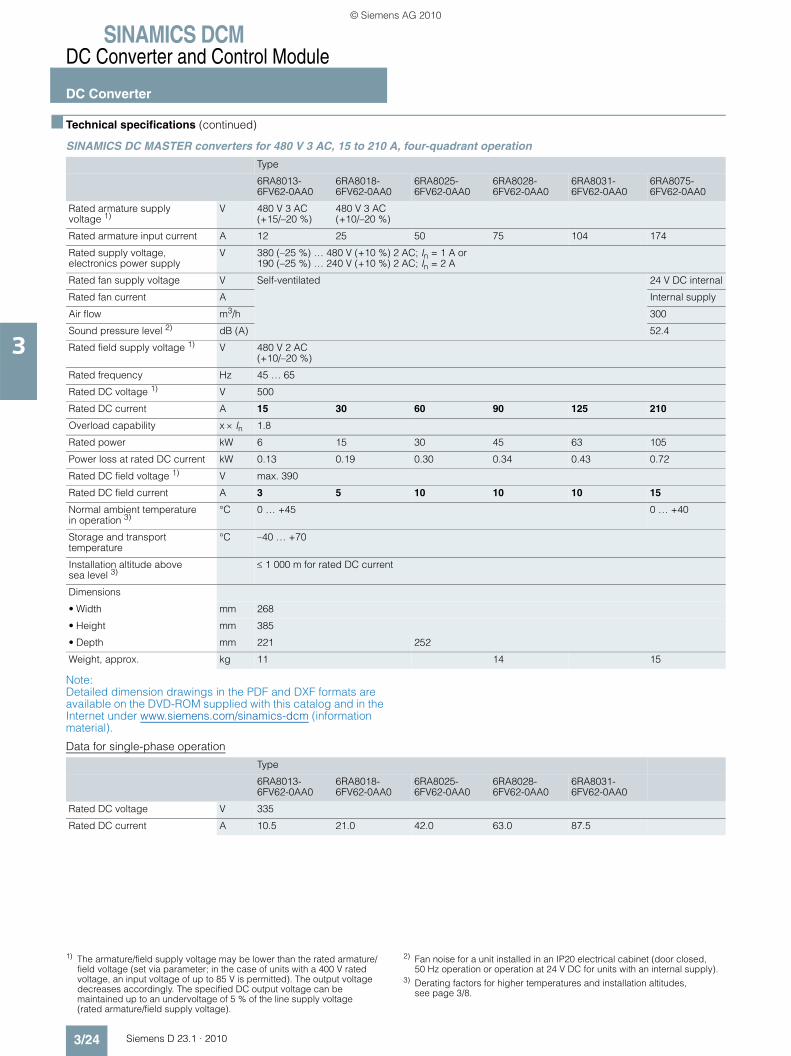
SINAMICS DCMDC Converter and Control Module
DC Converter
3/24 Siemens D 23.1 · 2010
3
■ Technical specifications (continued)
SINAMICS DC MASTER converters for 480 V 3 AC, 15 to 210 A, four-quadrant operation
Note: Detailed dimension drawings in the PDF and DXF formats are available on the DVD-ROM supplied with this catalog and in the Internet under www.siemens.com/sinamics-dcm (information material).
Data for single-phase operation
Type
6RA8013-6FV62-0AA0
6RA8018-6FV62-0AA0
6RA8025-6FV62-0AA0
6RA8028-6FV62-0AA0
6RA8031-6FV62-0AA0
6RA8075-6FV62-0AA0
Rated armature supply voltage 1)
V 480 V 3 AC (+15/–20 %)
480 V 3 AC (+10/–20 %)
Rated armature input current A 12 25 50 75 104 174
Rated supply voltage, electronics power supply
V 380 (–25 %) … 480 V (+10 %) 2 AC; In = 1 A or190 (–25 %) … 240 V (+10 %) 2 AC; In = 2 A
Rated fan supply voltage V Self-ventilated 24 V DC internal
Rated fan current A Internal supply
Air flow m3/h 300
Sound pressure level 2) dB (A) 52.4
Rated field supply voltage 1) V 480 V 2 AC (+10/–20 %)
Rated frequency Hz 45 … 65
Rated DC voltage 1) V 500
Rated DC current A 15 30 60 90 125 210
Overload capability x × In 1.8
Rated power kW 6 15 30 45 63 105
Power loss at rated DC current kW 0.13 0.19 0.30 0.34 0.43 0.72
Rated DC field voltage 1) V max. 390
Rated DC field current A 3 5 10 10 10 15
Normal ambient temperature in operation 3)
°C 0 … +45 0 … +40
Storage and transport temperature
°C –40 … +70
Installation altitude above sea level 3)
≤ 1 000 m for rated DC current
Dimensions
• Width mm 268
• Height mm 385
• Depth mm 221 252
Weight, approx. kg 11 14 15
Type
6RA8013-6FV62-0AA0
6RA8018-6FV62-0AA0
6RA8025-6FV62-0AA0
6RA8028-6FV62-0AA0
6RA8031-6FV62-0AA0
Rated DC voltage V 335
Rated DC current A 10.5 21.0 42.0 63.0 87.5
1) The armature/field supply voltage may be lower than the rated armature/field voltage (set via parameter; in the case of units with a 400 V rated voltage, an input voltage of up to 85 V is permitted). The output voltage decreases accordingly. The specified DC output voltage can be maintained up to an undervoltage of 5 % of the line supply voltage (rated armature/field supply voltage).
2) Fan noise for a unit installed in an IP20 electrical cabinet (door closed, 50 Hz operation or operation at 24 V DC for units with an internal supply).
3) Derating factors for higher temperatures and installation altitudes, see page 3/8.
© Siemens AG 2010
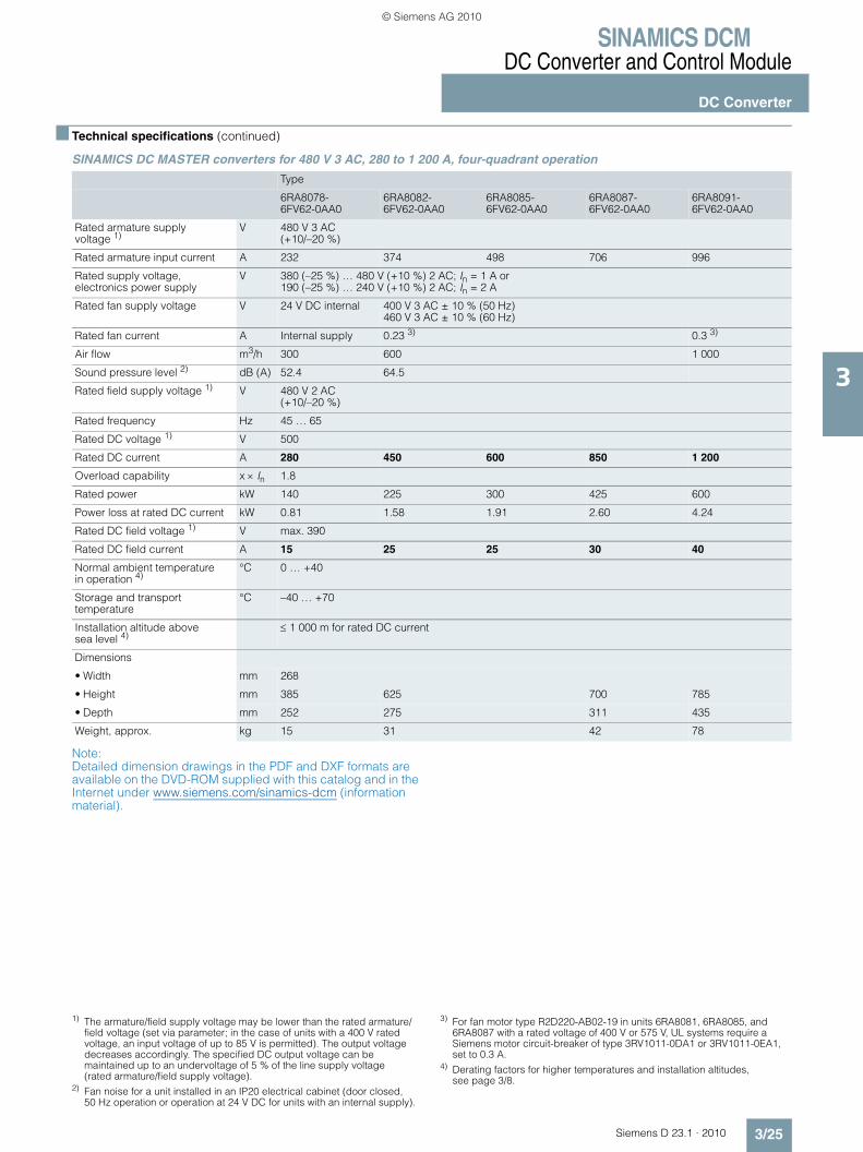
SINAMICS DCMDC Converter and Control Module
DC Converter
3/25Siemens D 23.1 · 2010
3
■ Technical specifications (continued)
SINAMICS DC MASTER converters for 480 V 3 AC, 280 to 1 200 A, four-quadrant operation
Note: Detailed dimension drawings in the PDF and DXF formats are available on the DVD-ROM supplied with this catalog and in the Internet under www.siemens.com/sinamics-dcm (information material).
Type
6RA8078-6FV62-0AA0
6RA8082-6FV62-0AA0
6RA8085-6FV62-0AA0
6RA8087-6FV62-0AA0
6RA8091-6FV62-0AA0
Rated armature supply voltage 1)
V 480 V 3 AC (+10/–20 %)
Rated armature input current A 232 374 498 706 996
Rated supply voltage, electronics power supply
V 380 (–25 %) … 480 V (+10 %) 2 AC; In = 1 A or190 (–25 %) … 240 V (+10 %) 2 AC; In = 2 A
Rated fan supply voltage V 24 V DC internal 400 V 3 AC ± 10 % (50 Hz) 460 V 3 AC ± 10 % (60 Hz)
Rated fan current A Internal supply 0.23 3) 0.3 3)
Air flow m3/h 300 600 1 000
Sound pressure level 2) dB (A) 52.4 64.5
Rated field supply voltage 1) V 480 V 2 AC (+10/–20 %)
Rated frequency Hz 45 … 65
Rated DC voltage 1) V 500
Rated DC current A 280 450 600 850 1 200
Overload capability x × In 1.8
Rated power kW 140 225 300 425 600
Power loss at rated DC current kW 0.81 1.58 1.91 2.60 4.24
Rated DC field voltage 1) V max. 390
Rated DC field current A 15 25 25 30 40
Normal ambient temperature in operation 4)
°C 0 … +40
Storage and transport temperature
°C –40 … +70
Installation altitude above sea level 4)
≤ 1 000 m for rated DC current
Dimensions
• Width mm 268
• Height mm 385 625 700 785
• Depth mm 252 275 311 435
Weight, approx. kg 15 31 42 78
1) The armature/field supply voltage may be lower than the rated armature/field voltage (set via parameter; in the case of units with a 400 V rated voltage, an input voltage of up to 85 V is permitted). The output voltage decreases accordingly. The specified DC output voltage can be maintained up to an undervoltage of 5 % of the line supply voltage (rated armature/field supply voltage).
2) Fan noise for a unit installed in an IP20 electrical cabinet (door closed, 50 Hz operation or operation at 24 V DC for units with an internal supply).
3) For fan motor type R2D220-AB02-19 in units 6RA8081, 6RA8085, and 6RA8087 with a rated voltage of 400 V or 575 V, UL systems require a Siemens motor circuit-breaker of type 3RV1011-0DA1 or 3RV1011-0EA1, set to 0.3 A.
4) Derating factors for higher temperatures and installation altitudes, see page 3/8.
© Siemens AG 2010

SINAMICS DCMDC Converter and Control Module
DC Converter
3/26 Siemens D 23.1 · 2010
3
■ Technical specifications (continued)
SINAMICS DC MASTER converters for 575 V 3 AC, 60 to 850 A, four-quadrant operation
Note: Detailed dimension drawings in the PDF and DXF formats are available on the DVD-ROM supplied with this catalog and in the Internet under www.siemens.com/sinamics-dcm (information material).
Data for single-phase operation
Type
6RA8025-6GV62-0AA0
6RA8031-6GV62-0AA0
6RA8075-6GV62-0AA0
6RA8081-6GV62-0AA0
6RA8085-6GV62-0AA0
6RA8087-6GV62-0AA0
Rated armature supply voltage 1)
V 575 V 3 AC (+10/–20 %)
Rated armature input current A 50 104 174 332 498 706
Rated supply voltage, electronics power supply
V 380 (–25 %) … 480 V (+10 %) 2 AC; In = 1 A or190 (–25 %) … 240 V (+10 %) 2 AC; In = 2 A
Rated fan supply voltage V Self-ventilated 24 V DC internal 400 V 3 AC ± 10 % (50 Hz) 460 V 3 AC ± 10 % (60 Hz)
Rated fan current A Internal supply 0.23 3)
Air flow m3/h 300 600
Sound pressure level 2) dB (A) 52.4 64.5
Rated field supply voltage 1) V 480 V 2 AC (+10/–20 %)
Rated frequency Hz 45 … 65
Rated DC voltage 1) V 600
Rated DC current A 60 125 210 400 600 850
Overload capability x × In 1.8
Rated power kW 36 75 126 240 360 510
Power loss at rated DC current kW 0.27 0.46 0.74 1.60 2.00 2.83
Rated DC field voltage 1) V max. 390
Rated DC field current A 10 10 15 25 25 30
Normal ambient temperature in operation 4)
°C 0 … +45 0 … +40
Storage and transport temperature
°C –40 … +70
Installation altitude above sea level 4)
≤ 1 000 m for rated DC current
Dimensions
• Width mm 268
• Height mm 385 65 700
• Depth mm 252 275 311
Weight, approx. kg 11 14 15 26 31 42
Type
6RA8025-6GV62-0AA0
6RA8031-6GV62-0AA0
Rated DC voltage V 400
Rated DC current A 42.0 87.5
1) The armature/field supply voltage may be lower than the rated armature/field voltage (set via parameter; in the case of units with a 400 V rated voltage, an input voltage of up to 85 V is permitted). The output voltage decreases accordingly. The specified DC output voltage can be maintained up to an undervoltage of 5 % of the line supply voltage (rated armature/field supply voltage).
2) Fan noise for a unit installed in an IP20 electrical cabinet (door closed, 50 Hz operation or operation at 24 V DC for units with an internal supply).
3) For fan motor type R2D220-AB02-19 in units 6RA8081, 6RA8085, and 6RA8087 with a rated voltage of 400 V or 575 V, UL systems require a Siemens motor circuit-breaker of type 3RV1011-0DA1 or 3RV1011-0EA1, set to 0.3 A.
4) Derating factors for higher temperatures and installation altitudes, see page 3/8.
© Siemens AG 2010

SINAMICS DCMDC Converter and Control Module
DC Converter
3/27Siemens D 23.1 · 2010
3
■ Technical specifications (continued)
SINAMICS DC MASTER converters for 575 V 3 AC, 1 100 to 2 800 A, four-quadrant operation
Note: Detailed dimension drawings in the PDF and DXF formats are available on the DVD-ROM supplied with this catalog and in the Internet under www.siemens.com/sinamics-dcm (information material).
Type
6RA8090-6GV62-0AA0
6RA8093-4GV62-0AA0
6RA8095-4GV62-0AA0
6RA8096-4GV62-0AA0
6RA8097-4GV62-0AA0
Rated armature supply voltage 1)
V 575 V 3 AC (+10/–20 %)
Rated armature input current A 913 1 328 1 660 1 826 2 324
Rated supply voltage, electronics power supply
V 380 (–25 %) … 480 V (+10 %) 2 AC; In = 1 A or190 (–25 %) … 240 V (+10 %) 2 AC; In = 2 A
Rated fan supply voltage V 400 V 3 AC ± 10 % (50 Hz) 460 V 3 AC ± 10 % (60 Hz)
Rated fan current A 0.3 3) 1 4)
Air flow m3/h 1 000 2 400
Sound pressure level 2) dB (A) 64.5 75.6
Rated field supply voltage 1) V 480 V 2 AC (+10/–20 %)
Rated frequency Hz 45 … 65
Rated DC voltage 1) V 600
Rated DC current A 1 100 1 600 2 000 2 200 2 800
Overload capability x × In 1.8
Rated power kW 660 960 1 200 1 320 1 680
Power loss at rated DC current kW 4.02 6.04 7.07 7.39 10.53
Rated DC field voltage 1) V max. 390
Rated DC field current A 40
Normal ambient temperature in operation 5)
°C 0 … +40
Storage and transport temperature
°C –40 … +70
Installation altitude above sea level 5)
≤ 1 000 m for rated DC current
Dimensions
• Width mm 268 453
• Height mm 785 883
• Depth mm 435 505
Weight, approx. kg 78 155 185
1) The armature/field supply voltage may be lower than the rated armature/field voltage (set via parameter; in the case of units with a 400 V rated voltage, an input voltage of up to 85 V is permitted). The output voltage decreases accordingly. The specified DC output voltage can be maintained up to an undervoltage of 5 % of the line supply voltage (rated armature/field supply voltage).
2) Fan noise for a unit installed in an IP20 electrical cabinet (door closed, 50 Hz operation or operation at 24 V DC for units with an internal supply).
3) For fan motor type R2D220-AB02-19 in units 6RA8081, 6RA8085, and 6RA8087 with a rated voltage of 400 V or 575 V, UL systems require a Siemens motor circuit-breaker of type 3RV1011-0DA1 or 3RV1011-0EA1, set to 0.3 A.
4) For fan motor type RH28M-2DK.3F.1R in units 6RA8090, 6RA8091, 6RA8093, and 6RA8095 with a rated voltage of 400 V or 575 V, UL systems require a Siemens motor circuit-breaker of type 3RV1011-0KA1 or 3RV1011-1AA1, set to 1.25 A.
5) Derating factors for higher temperatures and installation altitudes, see page 3/8.
© Siemens AG 2010

SINAMICS DCMDC Converter and Control Module
DC Converter
3/28 Siemens D 23.1 · 2010
3
■ Technical specifications (continued)
SINAMICS DC MASTER converters for 690 V 3 AC, 760 to 2 600 A, four-quadrant operation
Note: Detailed dimension drawings in the PDF and DXF formats are available on the DVD-ROM supplied with this catalog and in the Internet under www.siemens.com/sinamics-dcm (information material).
Type
6RA8086-6KV62-0AA0
6RA8090-6KV62-0AA0
6RA8093-4KV62-0AA0
6RA8095-4KV62-0AA0
6RA8097-4KV62-0AA0
Rated armature supply voltage 1)
V 690 V 3 AC (+10/–20 %)
Rated armature input current A 631 830 1 245 1 660 2 158
Rated supply voltage, electronics power supply
V 380 (–25 %) … 480 V (+10 %) 2 AC; In = 1 A or190 (–25 %) … 240 V (+10 %) 2 AC; In = 2 A
Rated fan supply voltage V 400 V 3 AC ± 10 % (50 Hz) 460 V 3 AC ± 10 % (60 Hz)
Rated fan current A 0.23 3) 0.3 3) 1 4)
Air flow m3/h 600 1 000 2 400
Sound pressure level 2) dB (A) 64.5 75.6
Rated field supply voltage 1) V 480 V 2 AC (+10/–20 %)
Rated frequency Hz 45 … 65
Rated DC voltage 1) V 725
Rated DC current A 760 1 000 1 500 2 000 2 600
Overload capability x × In 1.8
Rated power kW 551 725 1 088 1 450 1 885
Power loss at rated DC current kW 2.90 3.96 6.67 8.16 10.30
Rated DC field voltage 1) V max. 390
Rated DC field current A 30 40
Normal ambient temperature in operation 5)
°C 0 … +40
Storage and transport temperature
°C –40 … +70
Installation altitude above sea level 5)
≤ 1 000 m for rated DC current
Dimensions
• Width mm 268 453
• Height mm 700 785 883
• Depth mm 311 435 505
Weight, approx. kg 42 78 155 185
1) The armature/field supply voltage may be lower than the rated armature/field voltage (set via parameter; in the case of units with a 400 V rated voltage, an input voltage of up to 85 V is permitted). The output voltage decreases accordingly. The specified DC output voltage can be maintained up to an undervoltage of 5 % of the line supply voltage (rated armature/field supply voltage).
2) Fan noise for a unit installed in an IP20 electrical cabinet (door closed, 50 Hz operation or operation at 24 V DC for units with an internal supply).
3) For fan motor type R2D220-AB02-19 in units 6RA8081, 6RA8085, and 6RA8087 with a rated voltage of 400 V or 575 V, UL systems require a Siemens motor circuit-breaker of type 3RV1011-0DA1 or 3RV1011-0EA1, set to 0.3 A.
4) For fan motor type RH28M-2DK.3F.1R in units 6RA8090, 6RA8091, 6RA8093, and 6RA8095 with a rated voltage of 400 V or 575 V, UL systems require a Siemens motor circuit-breaker of type 3RV1011-0KA1 or 3RV1011-1AA1, set to 1.25 A.
5) Derating factors for higher temperatures and installation altitudes, see page 3/8.
© Siemens AG 2010

SINAMICS DCMDC Converter and Control Module
DC Converter
3/29Siemens D 23.1 · 2010
3
■ Technical specifications (continued)
SINAMICS DC MASTER converters for 830 V 3 AC, 950 to 1 900 A and 950 V 3 AC, 2 200 A, four-quadrant operation
Note: Detailed dimension drawings in the PDF and DXF formats are available on the DVD-ROM supplied with this catalog and in the Internet under www.siemens.com/sinamics-dcm (information material).
Type
6RA8088-6LV62-0AA0
6RA8093-4LV62-0AA0
6RA8095-4LV62-0AA0
6RA8096-4MV62-0AA0
Rated armature supply voltage 1)
V 830 V 3 AC (+10/–20 %)
950 V 3 AC (+15/–20 %)
Rated armature input current A 789 1 245 1 577 1 826
Rated supply voltage, electronics power supply
V 380 (–25 %) … 480 V (+10 %) 2 AC; In = 1 A or190 (–25 %) … 240 V (+10 %) 2 AC; In = 2 A
Rated fan supply voltage V 400 V 3 AC ± 10 % (50 Hz) 460 V 3 AC ± 10 % (60 Hz)
Rated fan current A 0.3 3) 1 4)
Air flow m3/h 1 000 2 400
Sound pressure level 2) dB (A) 64.5 75.6
Rated field supply voltage 1) V 480 V 2 AC(+10/–20 %)
Rated frequency Hz 45 … 65
Rated DC voltage 1) V 875 1 000
Rated DC current A 950 1 500 1 900 2 200
Overload capability x × In 1.8
Rated power kW 831 1 313 1 663 2 200
Power loss at rated DC current kW 4.22 7.12 8.67 11.34
Rated DC field voltage 1) V max. 390
Rated DC field current A 40
Normal ambient temperature in operation 5)
°C 0 … +40
Storage and transport temperature
°C –40 … +70
Installation altitude above sea level 5)
≤ 1 000 m for rated DC current
Dimensions
• Width mm 268 453
• Height mm 785 883
• Depth mm 435 505
Weight, approx. kg 78 155 185
1) The armature/field supply voltage may be lower than the rated armature/field voltage (set via parameter; in the case of units with a 400 V rated voltage, an input voltage of up to 85 V is permitted). The output voltage decreases accordingly. The specified DC output voltage can be maintained up to an undervoltage of 5 % of the line supply voltage (rated armature/field supply voltage).
2) Fan noise for a unit installed in an IP20 electrical cabinet (door closed, 50 Hz operation or operation at 24 V DC for units with an internal supply).
3) For fan motor type R2D220-AB02-19 in units 6RA8081, 6RA8085, and 6RA8087 with a rated voltage of 400 V or 575 V, UL systems require a Siemens motor circuit-breaker of type 3RV1011-0DA1 or 3RV1011-0EA1, set to 0.3 A.
4) For fan motor type RH28M-2DK.3F.1R in units 6RA8090, 6RA8091, 6RA8093, and 6RA8095 with a rated voltage of 400 V or 575 V, UL systems require a Siemens motor circuit-breaker of type 3RV1011-0KA1 or 3RV1011-1AA1, set to 1.25 A.
5) Derating factors for higher temperatures and installation altitudes, see page 3/8.
© Siemens AG 2010

SINAMICS DCMDC Converter and Control Module
DC Converter
3/30 Siemens D 23.1 · 2010
3
■ Selection and ordering data
DC Converters for two-quadrant operation
Rated data DC Converter Fuses
Armature circuit Field circuit Armature circuit Field circuit
Rated supply voltage 1)
Rated DC voltage
Rated DC current
Rated power
Rated supply voltage 1)
Rated DC current
Order No. Phase DC current 2 each
V V A kW V A Type Type Type
400 V 3 AC 485 60 29 400 V 2 AC 10 6RA8025-6DS22-0AA0 3NE1817-0 – 5SD420
90 44 10 6RA8028-6DS22-0AA0 3NE1820-0 – 5SD420
125 61 10 6RA8031-6DS22-0AA0 3NE1021-0 – 5SD420
210 102 15 6RA8075-6DS22-0AA0 3NE3227 – 5SD440
280 136 15 6RA8078-6DS22-0AA0 3NE3231 – 5SD440
400 194 25 6RA8081-6DS22-0AA0 3NE3233 – 5SD440
600 291 25 6RA8085-6DS22-0AA0 3NE3336 – 5SD440
850 412 30 6RA8087-6DS22-0AA0 3NE3338-8 – 5SD480
1 200 582 480 V 2 AC 40 6RA8091-6DS22-0AA0 – 2) – 3NE1802-0 3)
1 600 776 40 6RA8093-4DS22-0AA0 – 2) – 3NE1802-0 3)
2 000 970 40 6RA8095-4DS22-0AA0 – 2) – 3NE1802-0 3)
3 000 1 455 40 6RA8098-4DS22-0AA0 – 2) – 3NE1802-0 3)
480 V 3 AC 575 60 35 480 V 2 AC 10 6RA8025-6FS22-0AA0 3NE1817-0 – 5SD420
90 52 10 6RA8028-6FS22-0AA0 3NE1820-0 – 5SD420
125 72 10 6RA8031-6FS22-0AA0 3NE1021-0 – 5SD420
210 121 15 6RA8075-6FS22-0AA0 3NE3227 – 5SD440
280 161 15 6RA8078-6FS22-0AA0 3NE3231 – 5SD440
450 259 25 6RA8082-6FS22-0AA0 3NE3233 – 5SD440
600 345 25 6RA8085-6FS22-0AA0 3NE3336 – 5SD440
850 489 30 6RA8087-6FS22-0AA0 3NE3338-8 – 5SD480
1 200 690 40 6RA8091-6FS22-0AA0 – 2) – 3NE1802-0 3)
575 V 3 AC 690 60 41 480 V 2 AC 10 6RA8025-6GS22-0AA0 3NE1817-0 – 5SD420
125 86 10 6RA8031-6GS22-0AA0 3NE1021-0 – 5SD420
210 145 15 6RA8075-6GS22-0AA0 3NE3227 – 5SD440
400 276 25 6RA8081-6GS22-0AA0 3NE3233 – 5SD440
600 414 25 6RA8085-6GS22-0AA0 3NE3336 – 5SD440
800 552 30 6RA8087-6GS22-0AA0 3NE3338-8 – 5SD480
1 100 759 40 6RA8090-6GS22-0AA0 – 2) – 3NE1802-0 3)
1 600 1 104 40 6RA8093-4GS22-0AA0 – 2) – 3NE1802-0 3)
2 000 1 380 40 6RA8095-4GS22-0AA0 – 2) – 3NE1802-0 3)
2 200 1 518 40 6RA8096-4GS22-0AA0 – 2) – 3NE1802-0 3)
2 800 1 932 40 6RA8097-4GS22-0AA0 – 2) – 3NE1802-0 3)
690 V 3 AC 830 720 598 480 V 2 AC 30 6RA8086-6KS22-0AA0 3NE3337-8 – 5SD480
1 000 830 40 6RA8090-6KS22-0AA0 – 2) – 3NE1802-0 3)
1 500 1 245 40 6RA8093-4KS22-0AA0 – 2) – 3NE1802-0 3)
2 000 1 660 40 6RA8095-4KS22-0AA0 – 2) – 3NE1802-0 3)
2 600 2 158 40 6RA8097-4KS22-0AA0 – 2) – 3NE1802-0 3)
830 V 3 AC 1 000 950 950 480 V 2 AC 40 6RA8088-6LS22-0AA0 – 2) – 3NE1802-0 3)
1 500 1 500 40 6RA8093-4LS22-0AA0 – 2) – 3NE1802-0 3)
1 900 1 900 40 6RA8095-4LS22-0AA0 – 2) – 3NE1802-0 3)
950 V 3 AC 1 140 2 200 2 508 480 V 2 AC 40 6RA8096-4MS22-0AA0 – 2) – 3NE1802-0 3)
1) 50/60 Hz2) Arm fuses included in the unit, external semiconductor fuses not required.3) UL-recognized
© Siemens AG 2010

SINAMICS DCMDC Converter and Control Module
DC Converter
3/31Siemens D 23.1 · 2010
3
■ Selection and ordering data (continued)
DC Converters for four-quadrant operation
Rated data DC Converter Fuses
Armature circuit Field circuit Armature circuit Field circuit
Rated supply voltage 1)
Rated DC voltage
Rated DC current
Rated power
Rated supply voltage 1)
Rated DC current
Order No. Phase DC current 2 each
V V A kW V A Type Type Type
400 V 3 AC 420 15 6.3 400 V 2 AC 3 6RA8013-6DV62-0AA0 3NE1814-0 3NE1814-0 5SD420
30 12.6 5 6RA8018-6DV62-0AA0 3NE8003-1 3NE4102 5SD420
60 25 10 6RA8025-6DV62-0AA0 3NE1817-0 3NE4120 5SD420
90 38 10 6RA8028-6DV62-0AA0 3NE1820-0 3NE4122 5SD420
125 53 10 6RA8031-6DV62-0AA0 3NE1021-0 3NE4124 5SD420
210 88 15 6RA8075-6DV62-0AA0 3NE3227 3NE3227 5SD440
280 118 15 6RA8078-6DV62-0AA0 3NE3231 3NE3231 5SD440
400 168 25 6RA8081-6DV62-0AA0 3NE3233 3NE3233 5SD440
600 252 25 6RA8085-6DV62-0AA0 3NE3336 3NE3336 5SD440
850 357 30 6RA8087-6DV62-0AA0 3NE3338-8 3NE3334-0B 3) 5SD480
1 200 504 480 V 2 AC 40 6RA8091-6DV62-0AA0 – 2) – 2) 3NE1802-0 4)
1 600 672 40 6RA8093-4DV62-0AA0 – 2) – 2) 3NE1802-0 4)
2 000 840 40 6RA8095-4DV62-0AA0 – 2) – 2) 3NE1802-0 4)
3 000 1 260 40 6RA8098-4DV62-0AA0 – 2) – 2) 3NE1802-0 4)
480 V 3 AC 500 15 6 480 V 2 AC 3 6RA8013-6FV62-0AA0 3NE1814-0 3NE1814-0 5SD420
30 15 5 6RA8018-6FV62-0AA0 3NE1815-0 3NE4102 5SD420
60 30 10 6RA8025-6FV62-0AA0 3NE1817-0 3NE4120 5SD420
90 45 10 6RA8028-6FV62-0AA0 3NE1820-0 3NE4122 5SD420
125 63 10 6RA8031-6FV62-0AA0 3NE1021-0 3NE4124 5SD420
210 105 15 6RA8075-6FV62-0AA0 3NE3227 3NE3227 5SD440
280 140 15 6RA8078-6FV62-0AA0 3NE3231 3NE3231 5SD440
450 225 25 6RA8082-6FV62-0AA0 3NE3233 3NE3334-0B 5SD440
600 300 25 6RA8085-6FV62-0AA0 3NE3336 3NE3336 5SD440
850 425 30 6RA8087-6FV62-0AA0 3NE3338-8 3NE3334-0B 3) 5SD480
1 200 600 40 6RA8091-6FV62-0AA0 – 2) – 2) 3NE1802-0 4)
575 V 3 AC 600 60 36 480 V 2 AC 10 6RA8025-6GV62-0AA0 3NE1817-0 3NE4120 5SD420
125 75 10 6RA8031-6GV62-0AA0 3NE1021-0 3NE4124 5SD420
210 126 15 6RA8075-6GV62-0AA0 3NE3227 3NE3227 5SD440
400 240 25 6RA8081-6GV62-0AA0 3NE3233 3NE3233 5SD440
600 360 25 6RA8085-6GV62-0AA0 3NE3336 3NE3336 5SD440
850 510 30 6RA8087-6GV62-0AA0 3NE3338-8 3NE3334-0B 3) 5SD480
1 100 660 40 6RA8090-6GV62-0AA0 – 2) – 2) 3NE1802-0 4)
1 600 960 40 6RA8093-4GV62-0AA0 – 2) – 2) 3NE1802-0 4)
2 000 1 200 40 6RA8095-4GV62-0AA0 – 2) – 2) 3NE1802-0 4)
2 200 1 320 40 6RA8096-4GV62-0AA0 – 2) – 2) 3NE1802-0 4)
2 800 1 680 40 6RA8097-4GV62-0AA0 – 2) – 2) 3NE1802-0 4)
690 V 3 AC 725 760 551 480 V 2 AC 30 6RA8086-6KV62-0AA0 3NE3337-8 3NE3334-0B 3) 5SD420
1 000 725 40 6RA8090-6KV62-0AA0 – 2) – 2) 3NE1802-0 4)
1 500 1 088 40 6RA8093-4KV62-0AA0 – 2) – 2) 3NE1802-0 4)
2 000 1 450 40 6RA8095-4KV62-0AA0 – 2) – 2) 3NE1802-0 4)
2 600 1 885 40 6RA8097-4KV62-0AA0 – 2) – 2) 3NE1802-0 4)
830 V 3 AC 875 950 831 480 V 2 AC 40 6RA8088-6LV62-0AA0 – 2) – 2) 3NE1802-0 4)
1 500 1 313 40 6RA8093-4LV62-0AA0 – 2) – 2) 3NE1802-0 4)
1 900 1 663 40 6RA8095-4LV62-0AA0 – 2) – 2) 3NE1802-0 4)
950 V 3 AC 1 000 2 200 2 200 480 V 2 AC 40 6RA8096-4MV62-0AA0 – 2) – 2) 3NE1802-0 4)
1) 50/60 Hz2) Arm fuses included in the unit, external semiconductor fuses not required.
3) Two fuses connected in parallel.4) UL-recognized
© Siemens AG 2010

SINAMICS DCMDC Converter and Control Module
DC Converter
3/32 Siemens D 23.1 · 2010
3
■ Options
Note:
When ordering a unit with options, add the suffix “-Z” after the Order No. and then state the order code(s) for the desired option(s) after the suffix.
Example: 6RA8075-6GV62-0AA0-Z G00+G20+L85+...
See also ordering examples.
Available options
The following table provides an overview of the available options. Detailed descriptions of the options are provided in the section “Description of options”.
Designation Order code Notes Order No. for separate order
not coated coated
CUD
Standard CUD left (Standard) – 6RY1803-0AA00 6RY1803-0AA20
Advanced CUD left G00 – 6RY1803-0AA05 6RY1803-0AA25
Standard CUD right G10 This option requires an Advanced CUD left – order code G00
6RY1803-0AA00 +6RY1803-0GA00
6RY1803-0AA20 +6RY1803-0GA20
Advanced CUD right G11 This option requires an Advanced CUD left – order code G00
6RY1803-0AA05 +6RY1803-0GA00
6RY1803-0AA25 +6RY1803-0GA20
Communication Board CBE20 left G20 This option requires an Advanced CUD left – order code G00
– 6SL3055-0AA00-2EB0
Communication Board CBE20 right G21 This option requires an Advanced CUD right – order code G11
– 6SL3055-0AA00-2EB0
Memory card left S01 – 6RX1800-0AS01 –
Memory card right S02 This option requires a Standard CUD right – order code G10 – or an Advanced CUD right – order code G11
6RX1800-0AS01 –
Field
Field power section 1Q (Standard) – – 1) – 1)
Field power section 2Q L11 Only applicable for units from 60 to 3 000 A – 1) – 1)
Without field power section L10 Only applicable for units from 60 to 3 000 A – –
85 A field power section L85 Only applicable for units from 1 500 to 3 000 A
– 1) – 1)
Fans
Standard fan (Standard) Self-ventilated units do not have a fan – 1) –
Fan for single-phase connection L21 Only applicable for units from 400 to 1 200 A
– 1) –
Additional options
Electronics power supply for connection to 24 V DC
L05 Standard for Control Module, input voltage range 18 to 30 V, current consumption 5 A at 24 V
– 1) – 1)
Armature supply with extra-low voltage 10 to 50 V
L04 Only applicable for units up to ≤ 575 V rated supply voltage
– 1) – 1)
Coated PCBs M08 – – –
Nickel-plated copper busbars M10 Only applicable for units from 60 to 3 000 A – –
External sensor for ambient or inlet temperature
L15 Only applicable for units from 1 500 to 3 000 A
– 1) –
1) Available as spare part.
© Siemens AG 2010

SINAMICS DCMDC Converter and Control Module
DC Converter
3/33Siemens D 23.1 · 2010
3
■ Options (continued)
Option selection matrix
G00 G10 G11 G20 G21 L04 L05 L10 L11 L15 L21 L85 M08 M10 S01 S02
G00 ✓ ✓ ✓ ✓ ✓ ✓ ✓ ✓ ✓ ✓ ✓ ✓ ✓ ✓ ✓
G10 ✓ – ✓ – ✓ ✓ ✓ ✓ ✓ ✓ ✓ ✓ ✓ ✓ ✓
G11 ✓ – ✓ ✓ ✓ ✓ ✓ ✓ ✓ ✓ ✓ ✓ ✓ ✓ ✓
G20 ✓ ✓ ✓ ✓ ✓ ✓ ✓ ✓ ✓ ✓ ✓ ✓ ✓ ✓ ✓
G21 ✓ – ✓ ✓ ✓ ✓ ✓ ✓ ✓ ✓ ✓ ✓ ✓ ✓ ✓
L04 ✓ ✓ ✓ ✓ ✓ ✓ ✓ ✓ ✓ ✓ ✓ ✓ ✓ ✓ ✓
L05 ✓ ✓ ✓ ✓ ✓ ✓ ✓ ✓ ✓ ✓ ✓ ✓ ✓ ✓ ✓
L10 ✓ ✓ ✓ ✓ ✓ ✓ ✓ – ✓ ✓ – ✓ ✓ ✓ ✓
L11 ✓ ✓ ✓ ✓ ✓ ✓ ✓ – ✓ ✓ ✓ ✓ ✓ ✓ ✓
L15 ✓ ✓ ✓ ✓ ✓ ✓ ✓ ✓ ✓ ✓ ✓ ✓ ✓ ✓ ✓
L21 ✓ ✓ ✓ ✓ ✓ ✓ ✓ ✓ ✓ ✓ ✓ ✓ ✓ ✓ ✓
L85 ✓ ✓ ✓ ✓ ✓ ✓ ✓ – ✓ ✓ ✓ ✓ ✓ ✓ ✓
M08 ✓ ✓ ✓ ✓ ✓ ✓ ✓ ✓ ✓ ✓ ✓ ✓ ✓ ✓ ✓
M10 ✓ ✓ ✓ ✓ ✓ ✓ ✓ ✓ ✓ ✓ ✓ ✓ ✓ ✓ ✓
S01 ✓ ✓ ✓ ✓ ✓ ✓ ✓ ✓ ✓ ✓ ✓ ✓ ✓ ✓ ✓
S02 ✓ ✓ ✓ ✓ ✓ ✓ ✓ ✓ ✓ ✓ ✓ ✓ ✓ ✓ ✓
✓ Option can be combined without any restrictions
– Option cannot be combined
© Siemens AG 2010

SINAMICS DCMDC Converter and Control Module
DC Converter
3/34 Siemens D 23.1 · 2010
3
■ Options (continued)
Ordering examples
Example 1
Application:
A DC drive system is required for a cableway. A SINAMICS DC MASTER is to handle the closed-loop control of the selected 560 kW DC motor with a rated armature voltage of 420 V and a rated armature current of 1 306 A. Due to the overdimensioning of 25 % specified by the acceptance authorities, and due to the maximum ambient temperature of 45 °C that can occur, the rated current of the converter had to be further reduced by 5 %. This is the reason that a unit with a rated supply current of 2 000 A was selected. The converter capable of energy recov-ery is to be connected to a 400 V line supply. A PROFINET con-nection is required for the higher-level control.
Solution:
A four-quadrant converter with 2 000 A and 400 V AC should be selected for this application. The incremental encoder to sense the speed – mounted on the motor – is directly evaluated in the CUD of the SINAMICS DC MASTER, without requiring any addi-tional option.
The following options must be selected in order to permit the PROFINET connection:G00 (Advanced CUD left)G20 (PROFINET Communication Board CBE20 left)
The ordering data are as follows:6RA8095-4DV62-0AA0-ZG00+G20
Example 2
Application:
An unwinder for paper in a reeler-slitter is to be modernized – but the existing motor is to be kept. The power section is to be sup-plied from the existing 690 V supply. The technological control is to be implemented in the higher-level PCS7 system. The client specified PROFIBUS as the control and setpoint interface. The following measured values and status displays are to be visual-ized in the cabinet doors of the drive cabinet to facilitate fast and simple diagnostics for the service and maintenance personnel: Armature current, armature voltage, speed, field current, status messages – operation and fault.
The customer explained that he repeatedly had problems with the existing converter relating to overvoltage in the motor arma-ture circuit – and as a consequence, this resulted in tension fluc-tuations in the paper web when the motor went into the field-weakening range. As a result of instability in the control voltage supply, in the past, there were repeatedly failures that had a negative impact on the availability.
Solution:
As a result of the data of the existing motor and the customer specifications relating to acceleration and braking ramps, tambour roll weight and maximum diameter, a four-quadrant converter was selected with a rated supply voltage of 690 V and a rated current of 1 500 A. The dynamic overload capability of the units is utilized to brake the drive when the paper web breaks.
The technological control with current setpoint interface is realized in the higher-level control. This is the reason that for this particular application, the Standard CUD is sufficient, which already has an integrated Profibus interface.
The problem with armature overvoltages when entering the field weakening range has now been resolved by selecting the two-quadrant field power section option. By actively reducing the current using a counter-voltage, the field current actual value can now follow the field current setpoint – even for steep accel-eration ramps – and therefore overvoltages are avoided in the ar-mature circuit. The tension fluctuations in the paper web are con-sequentially eliminated.
Selecting the option “Electronics power supply for connection to 24 V DC” means that the drive system can be intergrated into a favorably-priced and low-maintenance DC UPS system com-prising SITOP components.
The requirements regarding actual value and status displays were addressed by installing the AOP30 Advanced Operator Panel in the doors of the drive cabinet.
Coated PCBs and nickel-plated copper busbars were selected as a result of the aggressive atmosphere with a high percentage of H2S.
The availability of equipment is extremely important in the paper industry. This is the reason that the option “memory card left” was selected to allow service and maintenance personnel short repair times in the case of faults. Software and additional lan-guages of the AOP text are saved on this card. Further, parame-ter values can be additionally saved there and there is a re-served memory range for offline long-time trace records.
The following options must be selected for this particular appli-cation: L05 (electronics power supply for connection to 24 V DC) L11 (2Q field power section) M08 (coated PCBs) M10 (nickel-plated copper busbars) S01 (memory card left)
Further, the following accessories are required: Advanced Operator Panel AOP30 (6SL3055-0AA00-4CA)RS485 cable, 3 m long
The ordering data are as follows: 6RA8093-4KV62-0AA0-ZL05+L11+M08+M10+S01and 6SL3055-0AA00-4CA as well as 6RY1807-0AP00
© Siemens AG 2010

SINAMICS DCMDC Converter and Control Module
DC Converter
3/35Siemens D 23.1 · 2010
3
■ Options (continued)
Description of options
G00 Advanced CUD left
In addition to the connections and functions of the Standard CUD, the Advanced CUD has two DRIVE-CLiQ connections and one option slot. The use of an Advanced CUD also provides the opportunity of inserting an additional CUD (Standard or Advanced) to increase the computational performance and the number of terminals. This can be used, e.g. to implement addi-tional technological functions.
By using an Advanced CUD, which is located in the lefthand slot instead of the Standard CUD, the SINAMICS SMC30, TM15, TM31 and CBE20 components can be connected to the SINAMICS DC MASTER. More detailed information on the SINAMICS components is available in the catalog section “Accessories and supplementary components”.
G10 Standard CUD right
Selecting option G10 provides the possibility of further increas-ing the performance of technology functions for the SINAMICS DC MASTER. As a result of the additional Standard CUD that is inserted in the righthand slot of the electronics tray, users have additional computational performance at their fingertips in order to fulfill even the highest demands when it comes to closed-loop control performance. Option G00 is required when selecting op-tion G10. An extension to include two Control Units is only pos-sible when the Advanced CUD is inserted in the lefthand slot.
G11 Advanced CUD right
With option G11, users can address the highest demands re-garding the closed-loop control performance and use the wide range of interfaces. With this option, in addition to the Advanced CUD located in the lefthand slot, an additional Advanced CUD can be mounted in the righthand slot. This therefore doubles the number of interfaces of the SINAMICS DC MASTER. Option G00 is required when selecting option G11. An extension to include two Control Units is only possible when the Advanced CUD is inserted in the lefthand slot.
G20 Communication Board CBE20 left
The CBE20 Communication Board can be used to connect to a PROFINET IO network via the Advanced CUD.
The SINAMICS DC MASTER then assumes the function of a PROFINET IO device in the sense of PROFINET and offers the following functions:• PROFINET IO device• 100 Mbits/s full duplex• Supports real-time classes of PROFINET IO:• RT (Real-Time)• Connection to control systems as PROFINET IO devices in
accordance with PROFIdrive, Specification V4.1.• In addition to PROFIBUS (standard), PROFINET can also be
used for engineering with the STARTER commissioning tool.• Integrated 4-port switch with four RJ45 sockets based on the
PROFINET ASIC ERTEC400. The optimum topology (line, star, tree) can therefore be configured without additional external switches.
• The SINAMICS Link function can be used in conjunction with option S01 or S02.
The CBE20 is inserted in the option slot of the Advanced CUD, which is inserted in the lefthand slot. An Advanced CUD must be located in the lefthand slot in order to be able to use option G20. This can be selected with option G00.
The cables are sold by the meter.
For further information about connectors and cables, refer to Catalog IK PI.
Technical data
Permissible ambient temperature
• Storage and transport –40 ... +70 °C
• Operation 0 ... 55 °C
Approvals cULus (File No.: E164110)
Accessories for CBE20 Type
Industrial Ethernet FC
• RJ45 Plug 145 (1 plug) 6GK1901-1BB30-0AA0
• RJ45 Plug 145 (10 plugs) 6GK1901-1BB30-0AB0
• Stripping tool 6GK1901-1GA00
• Standard cable GP 2x2 6XV1840-2AH10
• Flexible cable GP 2x2 6XV1870-2B
• Trailing cable GP 2x2 6XV1870-2D
• Trailing cable 2x2 6XV1840-3AH10
• Marine cable 2x2 6XV1840-4AH10
© Siemens AG 2010

SINAMICS DCMDC Converter and Control Module
DC Converter
3/36 Siemens D 23.1 · 2010
3
■ Options (continued)
G21 Communication Board CBE20 right
With option G21, an Advanced CUD inserted in the righthand slot (refer to option G11) can be extended by the CBE20. More detailed information on the functionality, selection and ordering data of the CBE20 is available under option G20.
L04 Armature supply with extra-low voltage 10 to 50 V
With option L04, the SINAMICS DC MASTER is re-equipped for operation with 10 to 50 V AC. This is frequently required espe-cially for electrochemical applications, when controlling sole-noids, when using the converter to supply the fields of special motors or Ward-Leonard converters (MG sets).
This option can only be selected for units with rated supply voltages of up to 575 V.
L05 Electronics power supply for connection to 24 V DC
With option L05, users have the possibility of equipping SINAMICS DC MASTER with an electronics power supply for connection to 24 V DC instead of the standard electronics power supply. This option allows users to connect the units to a favor-ably-priced 24 V UPS system.
This option cannot be selected for Control Modules as the Control Module is supplied as standard with an electronics power supply for connection to 24 V DC. Input voltage range: 18 to 30 V, current consumption: 5 A at 24 V
L10 Without field power section
In some applications it may be necessary to individually adapt the field power section. For this particular case, users can order option L10 where SINAMICS DC MASTER is not equipped with the standard integrated field power section. This then allows them to implement their own individual solutions for the field power section.
This option cannot be ordered for units with rated DC currents from 15 to 30 A.
L11 2Q field power section
For applications that demand high speed field current changes, by specifying option L11, the SINAMICS DC MASTER can be equipped with a two-quadrant field with active current reduction. Further, this field power section has an integrated field overvolt-age protection.
This option cannot be ordered for units with rated DC currents from 15 to 30 A.
L15 External sensor for ambient or inlet temperature
Option L15 is a sensor located outside the unit to measure the ambient or inlet temperature. For example, this can be used to simply monitor the cabinet temperature and/or identify when the air intake filter is blocked.
This option is only available for units with rated DC currents from 1 500 to 3 000 A.
L21 Fan for single-phase connection
A fan can be optionally supplied with a single-phase connection for units with rated DC currents between 400 and 1 200 A. This allows fans to be more quickly replaced than three-phase fans – especially as the direction of rotation does not have to be checked.
Units smaller than 400 A are self-ventilated or have an integrated 24 V DC fan. Units with ratings of greater than 1 200 A require a three-phase connection for the fan due to the higher power con-sumption. Rated supply voltage: 230 V 1 AC ± 10 % (50 and 60 Hz).
L85 85 A field power section
With option L85, users can have the SINAMICS DC MASTER equipped with a rated DC field current of 85 A.
This option can only be ordered for units with rated DC currents from 1 500 to 3 000 A.
M08 Coated PCBs
In order to improve the reliability for increased degrees of pollu-tion and climatic stressing, it is possible to order PCBs of the SINAMICS DC MASTER that are coated on both sides by spec-ifying option M08.
M10 Nickel-plated copper busbars
When ordered with Option M10, the SINAMICS DC MASTER is equipped with nickel-plated copper busbars. The degree of availability can be increased for aggressive atmospheres.
This option is not available for units with rated DC currents from 15 to 30 A.
S01 Memory card left
With option S01, users receive a memory card for one Standard CUD or one Advanced CUD, which is inserted in the lefthand slot.
This memory card offers the following options: • Additional languages can be downloaded to the Advanced
Operator Panel AOP30. When using two CUDs, option S01 and option S02 must be ordered.
• Perform an offline long-time trace. • Download the DCC block library into the drive.• Update the software.
The SINAMICS Link function requires that the memory card is always inserted.
S02 Memory card right
With option S02, users receive a memory card for one Standard CUD or one Advanced CUD, which is inserted in the righthand slot.
This memory card offers the following options: • Additional languages can be downloaded to the Advanced
Operator Panel AOP30. When using two CUDs, option S01 and option S02 must be ordered.
• Perform an offline long-time trace. • Download the DCC block library into the drive.• Update the software.
The SINAMICS Link function requires that the memory card is always inserted.
In order to be able to use option S02, a Standard CUD right (option G10) or an Advanced CUD right (option G11) is required.
© Siemens AG 2010
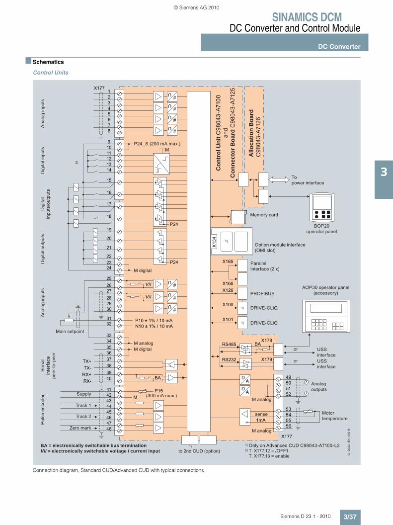
SINAMICS DCMDC Converter and Control Module
DC Converter
3/37Siemens D 23.1 · 2010
3
■ Schematics
Control Units
Connection diagram, Standard CUD/Advanced CUD with typical connections
#
U
#
U
#
U
#
U
#
U
#
U
#
U
G_D
023_
EN
_000
16USS interfaceUSS interface
Analog outputs
Motortemperature
Ana
log
inpu
tsA
nalo
g in
puts
Main setpoint
BA = electronically switchable bus terminationV/I = electronically switchable voltage / current input
Supply
Track 1
Track 2
Zero mark
Ser
ial
inte
rfac
e pe
er-to
-pee
r
Pul
se e
ncod
erD
igita
l inp
uts
Dig
ital o
utpu
tsD
igita
l in
puts
/out
puts
M analogM digital
M digital
P24_S (200 mA max.)
Con
trol
Uni
t C98
043-
A710
0 an
dC
onne
ctor
Boa
rd C
9804
3-A7
125
Allo
catio
n B
oard
C98
043-
A712
6
to 2nd CUD (option)
M analog
DRIVE-CLiQ
DRIVE-CLiQ
PROFIBUS
sense
M analog
To power interface
Memory card
BOP20operator panel
Option module interface(OMI slot)
Parallel interface (2 x)
AOP30 operator panel (accessory)
or
or
1) Only on Advanced CUD C98043-A7100-L22)
12345678
91011121314
15
16
17
18
19
20
21
222324
252627282930
3132
3334353637383940
4142434445464748
X177
TX+TX-
RX+RX-
M
M
P24
P24
X177
49505152
53545556
X165
X166X126
X100
X101
RS485
RS232
X13
4
1)
1)
1)P10 ± 1% / 10 mAN10 ± 1% / 10 mA
BA
P15
D
DA
A(300 mA max.)
X178BA
X179
CUD
1mA
V/I
V/I
1)
2)
© Siemens AG 2010

SINAMICS DCMDC Converter and Control Module
DC Converter
3/38 Siemens D 23.1 · 2010
3
■ Schematics (continued)
DC Converters
Connection diagram, DC Converters, 400 to 3 000 A, electronics power supply 400 V or 230 V, with fan
G_D
023_
EN
_000
17
Armature current
To A
lloca
tion
Boa
rd, C
UD
Electronics power supply
Power ON
Power interface
E-STOP
Analog tachometer
3 AC 50 … 60 Hz, 400 … 480 V
3 AC 50 … 60 Hz, 400 … 575 V
1 AC 50 … 60 Hz, 230 V
E-STOP orAnalog tachometer8 … 270 V
Fuse monitoring
Firing pulses, armature
Armature voltage
Line voltage, armature
Temperature monitoring
Temperature monitoring
Load resistor
Field module
Firing pulses, field
Line voltage, field
Field current actual value
1) Required for four-quadrant units2) Analog tachometer or pulse encoder
Shunt
Terminal XT1.103, 104
M ES/P24
XT1
103
104
XS1
105
106
XP1
5U1
5W1
5N1
XP1
5U1
5W1
5N1
XR1
K1
K1
109110
XT5
XT6
X7
X8
X11, X21
XS13
131312
12
3U1
3D 3C
M
G
1C1(1D1)
X177.41-48
1D1(1C1)
3W1
1)
2)
1U1
1V1
1W1
4U1
4V1
4W1
~ =
U#
U#
U#
...
U#
U#
M3 ~
K2
K3
© Siemens AG 2010
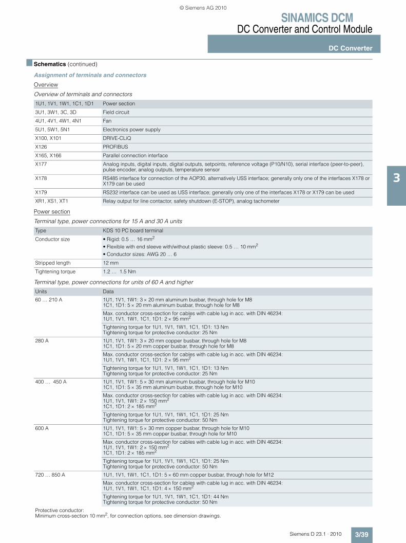
SINAMICS DCMDC Converter and Control Module
DC Converter
3/39Siemens D 23.1 · 2010
3
■ Schematics (continued)
Assignment of terminals and connectors
Overview
Overview of terminals and connectors
Power section
Terminal type, power connections for 15 A and 30 A units
Terminal type, power connections for units of 60 A and higher
1U1, 1V1, 1W1, 1C1, 1D1 Power section
3U1, 3W1, 3C, 3D Field circuit
4U1, 4V1, 4W1, 4N1 Fan
5U1, 5W1, 5N1 Electronics power supply
X100, X101 DRIVE-CLiQ
X126 PROFIBUS
X165, X166 Parallel connection interface
X177 Analog inputs, digital inputs, digital outputs, setpoints, reference voltage (P10/N10), serial interface (peer-to-peer), pulse encoder, analog outputs, temperature sensor
X178 RS485 interface for connection of the AOP30, alternatively USS interface; generally only one of the interfaces X178 or X179 can be used
X179 RS232 interface can be used as USS interface; generally only one of the interfaces X178 or X179 can be used
XR1, XS1, XT1 Relay output for line contactor, safety shutdown (E-STOP), analog tachometer
Type KDS 10 PC board terminal
Conductor size • Rigid: 0.5 … 16 mm2
• Flexible with end sleeve with/without plastic sleeve: 0.5 … 10 mm2
• Conductor sizes: AWG 20 … 6
Stripped length 12 mm
Tightening torque 1.2 … 1.5 Nm
Units Data
60 … 210 A 1U1, 1V1, 1W1: 3 × 20 mm aluminum busbar, through hole for M81C1, 1D1: 5 × 20 mm aluminum busbar, through hole for M8
Max. conductor cross-section for cables with cable lug in acc. with DIN 46234:1U1, 1V1, 1W1, 1C1, 1D1: 2 × 95 mm2
Tightening torque for 1U1, 1V1, 1W1, 1C1, 1D1: 13 NmTightening torque for protective conductor: 25 Nm
280 A 1U1, 1V1, 1W1: 3 × 20 mm copper busbar, through hole for M81C1, 1D1: 5 × 20 mm copper busbar, through hole for M8
Max. conductor cross-section for cables with cable lug in acc. with DIN 46234:1U1, 1V1, 1W1, 1C1, 1D1: 2 × 95 mm2
Tightening torque for 1U1, 1V1, 1W1, 1C1, 1D1: 13 NmTightening torque for protective conductor: 25 Nm
400 … 450 A 1U1, 1V1, 1W1: 5 × 30 mm aluminum busbar, through hole for M101C1, 1D1: 5 × 35 mm aluminum busbar, through hole for M10
Max. conductor cross-section for cables with cable lug in acc. with DIN 46234: 1U1, 1V1, 1W1: 2 × 150 mm2
1C1, 1D1: 2 × 185 mm2
Tightening torque for 1U1, 1V1, 1W1, 1C1, 1D1: 25 NmTightening torque for protective conductor: 50 Nm
600 A 1U1, 1V1, 1W1: 5 × 30 mm copper busbar, through hole for M101C1, 1D1: 5 × 35 mm copper busbar, through hole for M10
Max. conductor cross-section for cables with cable lug in acc. with DIN 46234: 1U1, 1V1, 1W1: 2 × 150 mm2
1C1, 1D1: 2 × 185 mm2
Tightening torque for 1U1, 1V1, 1W1, 1C1, 1D1: 25 NmTightening torque for protective conductor: 50 Nm
720 … 850 A 1U1, 1V1, 1W1, 1C1, 1D1: 5 × 60 mm copper busbar, through hole for M12
Max. conductor cross-section for cables with cable lug in acc. with DIN 46234:1U1, 1V1, 1W1, 1C1, 1D1: 4 × 150 mm2
Tightening torque for 1U1, 1V1, 1W1, 1C1, 1D1: 44 NmTightening torque for protective conductor: 50 Nm
Protective conductor:Minimum cross-section 10 mm2, for connection options, see dimension drawings.
© Siemens AG 2010

SINAMICS DCMDC Converter and Control Module
DC Converter
3/40 Siemens D 23.1 · 2010
3
■ Schematics (continued)
Terminal type, power connections for units of 60 A and higher (continued)
The units are designed for a permanent line supply connection in accordance with DIN VDE 0160-106, Section 6.5.2.1.
The conductor cross-sections must be determined in accordance with the regulations that apply in each case – e.g. DIN VDE 0276-1000.
Assignment of power connections
Field circuit
Terminal type, field circuit connections
Units Data
900 … 1 200 A 1U1, 1V1, 1W1, 1C1, 1D1: 10 × 80 mm copper busbar, through hole for M12
Max. conductor cross-section for cables with cable lug in acc. with DIN 46234:1U1, 1V1, 1W1, 1C1, 1D1: 4 × 150 mm2
Tightening torque for 1U1, 1V1, 1W1, 1C1, 1D1: 44 NmTightening torque for protective conductor: 60 Nm
1 500 … 2 000 A and2 200 A/575 V
1U1, 1V1, 1W1: 10 × 80 mm aluminum busbar, through hole for M121C1, 1D1: 10 × 50 mm aluminum busbar, through hole for M12
Max. conductor cross-section for cables with cable lug in acc. with DIN 46234: 1U1, 1V1, 1W1: 4 × 240 mm2
1C1, 1D1: 8 × 240 mm2
Tightening torque for 1U1, 1V1, 1W1, 1C1, 1D1: 44 NmTightening torque for protective conductor: 60 Nm
2 200 A (> 575 V) … 3 000 A 1U1, 1V1, 1W1: 2x 10 × 100 mm copper busbar, through hole for M121C1, 1D1: 2x 10 × 80 mm copper busbar, through hole for M12
Tightening torque for 1U1, 1V1, 1W1, 1C1, 1D1: 44 NmTightening torque for protective conductor: 60 Nm
Protective conductor:Minimum cross-section 10 mm2, for connection options, see dimension drawings.
Terminal Function Technical data
1U11V11W1
Line input armature power section See under “Technical specifications” (Rated armature supply voltage)
Protective conductor PE
1C1 (1D1)1D1 (1C1)
Motor connection armature circuit See under “Technical specifications” (Rated DC voltage)
Units with power section C98043-A7111 (15 and 30 A units) and units with field module C98043-A7115 (the terminals are located on the module):
Type ZFKDS 4-10 PC board terminal
Conductor size • Rigid: 0.2 … 6 mm2
• Flexible: 0.2 … 4 mm2
• Conductor sizes: AWG 24 … 10• Flexible with end sleeve with/without plastic sleeve: 0.25 … 4 mm2
Stripped length 10 mm
Units with field module C98043-A7116 with rated armature DC current 900 … 1 200 A:
Type 20E/4DS terminal strip
Conductor size • Rigid: 6 … 16 mm2
• Flexible: 6 … 10 mm2
Stripped length 8 mm
Units with field module C98043-A7116 with rated armature DC current 1 500 … 3 000 A:
Type UK16N terminal block
Conductor size • Rigid: 2.5 … 25 mm2, AWG 14 … 4• Flexible: 4 … 16 mm2, AWG 12 … 6
Stripped length 11 mm
Tightening torque 1.5 … 1.8 Nm
© Siemens AG 2010

SINAMICS DCMDC Converter and Control Module
DC Converter
3/41Siemens D 23.1 · 2010
3
■ Schematics (continued)
Terminal type, field circuit connections (continued)
Assignment of connections for the field circuit
Electronics power supply
Terminal type, electronics power supply
Assignment of terminals for the electronics power supply
Note:
In the case of line supply voltages that fall outside the tolerance range, the electronics supply voltage, field circuit line supply connection, and the unit fan connection must be adapted to the permissible value using transformers. It is absolutely essential that you use an isolation transformer for rated line supply volt-ages above 480 V. The rated supply voltage for the armature circuit (index i00) and for the field circuit (index i01) must be set at p50078.
Units with option L85 (with rated field DC current 85 A):
Type UK35 terminal block
Conductor size • Rigid: 0.75 … 50 mm2
• Flexible: 0.75 … 35 mm2
• Conductor sizes: AWG 18 … 0/1• Flexible with end sleeve with/without plastic sleeve: 0.75 … 35 mm2
Stripped length 16 mm
Tightening torque 3.2 … 3.7 Nm
Terminal Function Technical data
XF1:3U1, 3W1
Line input armature power section field circuit
See under “Technical specifications” (Rated field supply voltage)
XF2-1: 3DXF2-2: 3C
Motor connection field circuit See under “Technical specifications” (Rated field DC voltage)
Type MSTB 2.5 / CIF plug-in terminal
Conductor size • Rigid: 0.2 … 2.5 mm2
• Flexible: 0.2 … 2.5 mm2
• Conductor sizes: AWG 24 … 12• Flexible with end sleeve with/without plastic sleeve: 0.25 … 2.5 mm2
Multi-conductor connection (2 conductors of the same type and with same cross-section): • Rigid: 0.2 … 1 mm2
• Flexible: 0.2 … 1.5 mm2
• Flexible with end sleeve without plastic sleeve: 0.25 … 1 mm2
• Flexible with end sleeve with plastic sleeve: 0.5 … 1.5 mm2
Stripped length 7 mm
Tightening torque 0.5 … 0.6 Nm
TerminalXP1
Connection Function Technical data
5U15W15N1
400 V supply 380 V (–25 %) … 480 V (+10 %) 2 AC; In = 1 A(–35 % for 1 min)Internal fuse with F200, F201 on module C98043-A7105 or -A7106 External protection max. 6 A, characteristic C recommended
or
5U15W15N1
230 V supply 190 V (–25 %) … 240 V (+10 %) 1 AC; In = 2 A(–35 % for 1 min)Internal fuse with F200, F201 on module C98043-A7105 or -A7106 External protection max. 6 A, characteristic C recommended
Module C98043-A7105 Power Interface 400 … 600 V or C98043-A7106 Power Interface 690 … 950 V
NC
© Siemens AG 2010

SINAMICS DCMDC Converter and Control Module
DC Converter
3/42 Siemens D 23.1 · 2010
3
■ Schematics (continued)
Fans
Terminal type, fan connections for units ≥ 400 A with forced ventilation
The connecting leads must be insulated up to the point where they meet the terminal enclosure.
Terminal assignment for fan connection
Open-loop and closed-loop control section
Terminal type, open-loop and closed-loop control section
Type DFK-PC4 plug-in terminal
Conductor size • Rigid: 0.2 … 4 mm2
• Flexible: 0.2 … 4 mm2
• Conductor sizes: AWG 24 … 10
Terminal Function Technical data
4U14V14W1
400 … 460 V supply 400 … 460 V 3 ACfor additional data, refer under “Technical specifications”
Protective conductor PE
or
4U14N1
230 V supply 230 V 1 ACfor additional data, refer under “Technical specifications”
X177:
Type SPT 1.5 spring-loaded terminal
Conductor size • Rigid: 0.2 … 1.5 mm2
• Flexible: 0.2 … 1.5 mm2
• Conductor sizes: AWG 24 … 16• Flexible with end sleeve without plastic sleeve: 0.25 … 1.5 mm2 (stripped length 8 mm)• Flexible with end sleeve with plastic sleeve: 0.25 … 0.75 mm2 (stripped length 8 mm)
Stripped length 10 mm
X178, X179:
Type FMC 1.5 plug-in terminal
Conductor size • Rigid: 0.2 … 1.5 mm2
• Flexible: 0.2 … 1.5 mm2
• Conductor sizes: AWG 24 … 16• Flexible with end sleeve without plastic sleeve: 0.25 … 1.5 mm2
• Flexible with end sleeve with plastic sleeve: 0.25 … 0.75 mm2
Stripped length 10 mm
XR1, XS1, XT1:
Type MSTB 2.5 / CIF plug-in terminal
Conductor size • Rigid: 0.2 … 2.5 mm2
• Flexible: 0.2 … 2.5 mm2
• Conductor sizes: AWG 24 … 12Flexible with end sleeve with/without plastic sleeve: 0.25 … 2.5 mm2
Stripped length 7 mm
Tightening torque 0.5 … 0.6 Nm
X126:
Type Submin D, 9-pin
X100, X101:
Type Western socket 8 / 4 (RJ45)
© Siemens AG 2010

SINAMICS DCMDC Converter and Control Module
DC Converter
3/43Siemens D 23.1 · 2010
3
■ Schematics (continued)
Terminals on Connector Board C98043-A7125
Assignment, terminal X177
TerminalX177
Function Technical data
Analog inputs (user-assignable inputs)
12
AI3 +AI3 -
Analog input 3 Input type (signal type):Differential input ± 10 V; 150 kΩResolution approx. 5.4 mV (± 11 bits)Common-mode controllability: ± 15 V3
4AI4 +AI4 -
Analog input 4
56
AI5 +AI5 -
Analog input 5
78
AI6 +AI6 -
Analog input 6
Digital inputs (user-assignable inputs)
910
24 V DC 24 V supply (output) 24 V DC, short-circuit proofMax. load 200 mA (terminals 9 and 10 together), internal supply referred to internal ground
11 DI0 Digital input 0 H signal: +15 … +30 VL signal: –30 … +5 V or terminal open8.5 mA at 24 V12 DI1 Digital input 1
13 DI2 Digital input 2
14 DI3 Digital input 3
Digital inputs/outputs (user-assignable inputs/outputs)
15 DI/DO4
Digital input/output 4
Type, input/output parameterizableProperties of inputs:H signal: +15 … +30 VL signal: 0 … +5 V or terminal open8.5 mA at 24 VProperties of outputs:H signal: +20 … +26 VL signal: 0 … +2 VShort-circuit proof, 100 mAInternal protective circuit (free wheeling diode)For overload: Alarm A60018
16 DI/DO5
Digital input/output 5
17 DI/DO6
Digital input/output 6
18 DI/DO7
Digital input/output 7
19 DO0 Digital output 0 H signal: +20 … +26 VL signal: 0 … +2 VShort-circuit proof, 100 mAInternal protective circuit (free wheeling diode)For overload: Alarm A60018
20 DO1 Digital output 1
21 DO2 Digital output 2
22 DO3 Digital output 3
23, 24 M Ground, digital
Analog inputs, setpoint inputs (user-assignable inputs)
2526
AI0 +AI0 -
Analog input 0Main setpoint
Input type (signal type), parameterizable:- Differential input ± 10 V; 150 kΩ- Current input 0 … 20 mA; 300 Ω or 4 … 20 mA; 300 ΩResolution approx. 0.66 mV (± 14 bits)Common-mode controllability: ± 15 V
2728
AI1 +AI1 -
Analog input 1
2930
AI2 +AI2 -
Analog input 2 Input type (signal type):- Differential input ± 10 V; 150 kΩResolution approx. 0.66 mV (± 14 bits)Common-mode controllability: ± 15 V
Reference voltage
3132
P10N10
Reference voltage ± 10 V (output)
Tolerance ± 1 % at 25 °C Stability 0.1 % per 10 K10 mA short-circuit proof
33, 34 M Ground, analog
Serial interface, peer-to-peer RS485
35, 36 M Ground, digital
37 TX+ Send cable + 4-wire send cable, positive differential output
38 TX- Send cable - 4-wire send cable, negative differential output
39 RX+ Receive cable + 4-wire receive cable, positive differential input
40 RX- Receive cable - 4-wire receive cable, negative differential input
© Siemens AG 2010
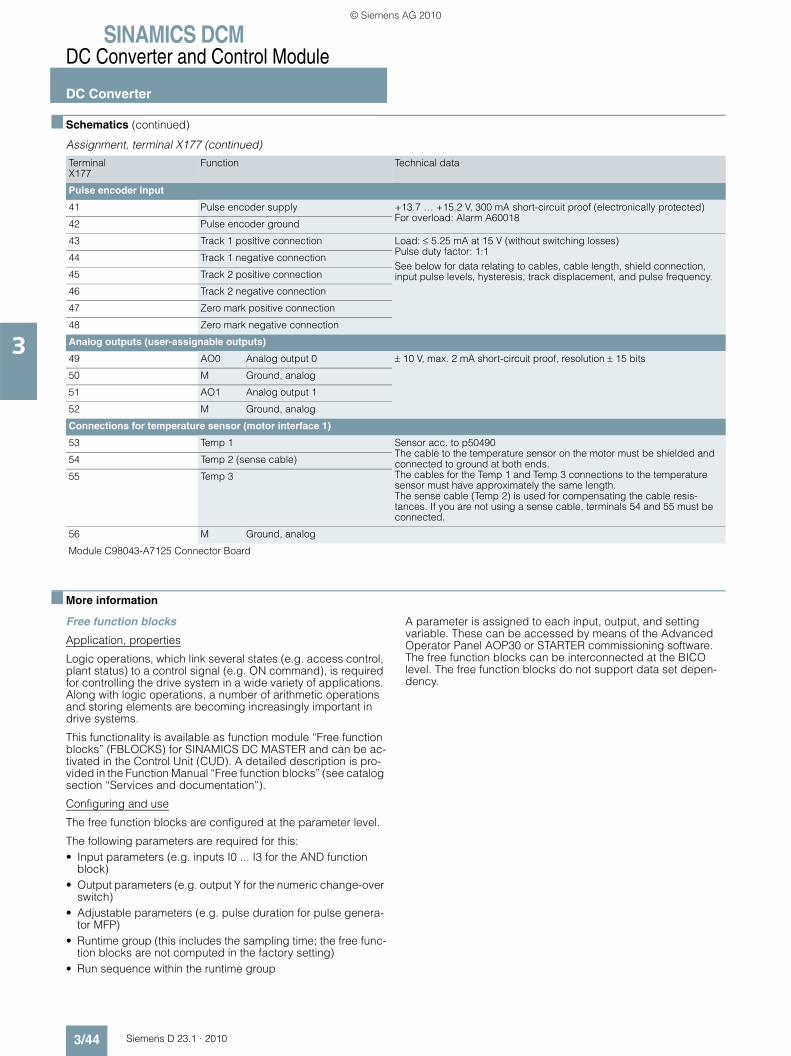
SINAMICS DCMDC Converter and Control Module
DC Converter
3/44 Siemens D 23.1 · 2010
3
■ Schematics (continued)
Assignment, terminal X177 (continued)
■ More information
Free function blocks
Application, properties
Logic operations, which link several states (e.g. access control, plant status) to a control signal (e.g. ON command), is required for controlling the drive system in a wide variety of applications. Along with logic operations, a number of arithmetic operations and storing elements are becoming increasingly important in drive systems.
This functionality is available as function module “Free function blocks” (FBLOCKS) for SINAMICS DC MASTER and can be ac-tivated in the Control Unit (CUD). A detailed description is pro-vided in the Function Manual “Free function blocks” (see catalog section “Services and documentation”).
Configuring and use
The free function blocks are configured at the parameter level.
The following parameters are required for this:• Input parameters (e.g. inputs I0 ... I3 for the AND function
block)• Output parameters (e.g. output Y for the numeric change-over
switch)• Adjustable parameters (e.g. pulse duration for pulse genera-
tor MFP)• Runtime group (this includes the sampling time; the free func-
tion blocks are not computed in the factory setting)• Run sequence within the runtime group
A parameter is assigned to each input, output, and setting variable. These can be accessed by means of the Advanced Operator Panel AOP30 or STARTER commissioning software. The free function blocks can be interconnected at the BICO level. The free function blocks do not support data set depen-dency.
TerminalX177
Function Technical data
Pulse encoder input
41 Pulse encoder supply +13.7 … +15.2 V, 300 mA short-circuit proof (electronically protected)For overload: Alarm A60018
42 Pulse encoder ground
43 Track 1 positive connection Load: ≤ 5.25 mA at 15 V (without switching losses)Pulse duty factor: 1:1See below for data relating to cables, cable length, shield connection, input pulse levels, hysteresis, track displacement, and pulse frequency.
44 Track 1 negative connection
45 Track 2 positive connection
46 Track 2 negative connection
47 Zero mark positive connection
48 Zero mark negative connection
Analog outputs (user-assignable outputs)
49 AO0 Analog output 0 ± 10 V, max. 2 mA short-circuit proof, resolution ± 15 bits
50 M Ground, analog
51 AO1 Analog output 1
52 M Ground, analog
Connections for temperature sensor (motor interface 1)
53 Temp 1 Sensor acc. to p50490The cable to the temperature sensor on the motor must be shielded and connected to ground at both ends.The cables for the Temp 1 and Temp 3 connections to the temperature sensor must have approximately the same length. The sense cable (Temp 2) is used for compensating the cable resis-tances. If you are not using a sense cable, terminals 54 and 55 must be connected.
54 Temp 2 (sense cable)
55 Temp 3
56 M Ground, analog
Module C98043-A7125 Connector Board
© Siemens AG 2010
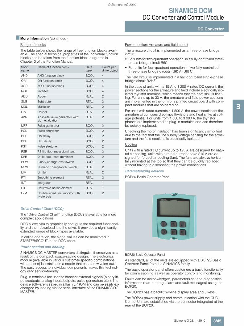
SINAMICS DCMDC Converter and Control Module
DC Converter
3/45Siemens D 23.1 · 2010
3
■ More information (continued)
Range of blocks
The table below shows the range of free function blocks avail-able. The special technical properties of the individual function blocks can be taken from the function block diagrams in Chapter 3 of the Function Manual.
Drive Control Chart (DCC)
The “Drive Control Chart” function (DCC) is available for more complex applications.
DCC allows you to graphically configure the required functional-ity and then download it to the drive. It provides a significantly extended range of block types available.
In online operation, the signal values can be monitored in STARTER/SCOUT in the DCC chart.
Power section and cooling
SINAMICS DC MASTER converters distinguish themselves as a result of the compact, space-saving design. The electronics module (available in various customer-specific combinations with options) is installed in a cradle that can be swiveled out. The easy access to individual components makes this technol-ogy very service-friendly.
Plug-in terminals are used to connect external signals (binary in-puts/outputs, analog inputs/outputs, pulse generators etc.). The device software is saved in a flash EPROM and can be easily ex-changed by loading via the serial interface of the SINAMICS DC MASTER.
Power section: Armature and field circuit
The armature circuit is implemented as a three-phase bridge circuit:• For units for two-quadrant operation, in a fully-controlled three-
phase bridge circuit B6C • For units for four-quadrant operation in two fully-controlled
three-phase bridge circuits (B6) A (B6) C.
The field circuit is implemented in a half-controlled single-phase bridge circuit B2HZ.
In the case of units with a 15 A to 1 200 A rated DC current, the power sections for the armature and field include electrically iso-lated thyristor modules, which means that the heat sink is float-ing. For units up to 30 A, the armature and field power sections are implemented in the form of a printed circuit board with com-pact modules that are soldered on.
For units with rated currents ≥ 1 500 A, the power section for the armature circuit uses disc-type thyristors and heat sinks at volt-age potential. For units from 1 500 to 3 000 A, the thyristor phases are implemented as plug-in modules and can therefore be quickly replaced.
Checking the motor insulation has been significantly simplified due to the fact that the line supply voltage sensing for the arma-ture and the field sections is electrically isolated.
Cooling
Units with a rated DC current up to 125 A are designed for natu-ral air cooling, units with a rated current above 210 A are de-signed for forced air cooling (fan). The fans are always horizon-tally mounted at the top so that they can be quickly replaced without having to disconnect the power connections.
Parameterizing devices
BOP20 Basic Operator Panel
BOP20 Basic Operator Panel
As standard, all of the units are equipped with a BOP20 Basic Operator Panel from the SINAMICS family.
The basic operator panel offers customers a basic functionality for commissioning as well as operator control and monitoring.
Faults can be acknowledged, parameters set and diagnostics information read-out (e.g. alarm and fault messages) using the BOP20.
The BOP20 has a backlit two-line display area and 6 keys.
The BOP20 power supply and communication with the CUD Control Unit are established via the connector integrated at the rear of the BOP20.
Short name
Name of function block Data type
Count per drive object
AND AND function block BOOL 4
OR OR function block BOOL 4
XOR XOR function block BOOL 4
NOT Inverter BOOL 4
ADD Adder REAL 2
SUB Subtracter REAL 2
MUL Multiplier REAL 2
DIV Divider REAL 2
AVA Absolute value generator with sign evaluation
REAL 2
MFP Pulse generator BOOL 2
PCL Pulse shortener BOOL 2
PDE ON delay BOOL 2
PDF OFF delay BOOL 2
PST Pulse stretcher BOOL 2
RSR RS flip-flop, reset dominant BOOL 2
DFR D flip-flop, reset dominant BOOL 2
BSW Binary change-over switch BOOL 2
NSW Numeric change-over switch REAL 2
LIM Limiter REAL 2
PT1 Smoothing element REAL 2
INT Integrator REAL 1
DIF Derivative-action element REAL 1
LVM Double-sided limit monitor with hysteresis
BOOL 2
© Siemens AG 2010

SINAMICS DCMDC Converter and Control Module
DC Converter
3/46 Siemens D 23.1 · 2010
3
■ More information (continued)
AOP30 Advanced Operator Panel
The AOP30 Advanced Operator Panel is an optional input/output device for SINAMICS DC MASTER converters. It can be sepa-rately ordered. Additional information on the AOP30 is available in the catalog section “Accessories and supplementary compo-nents”.
PC based parameterization
The STARTER tool is available for PC-based commissioning and diagnostics. More detailed information is provided in catalog section 5 “Tools and engineering”.
Closed-loop control and open-loop drive control
The closed-loop and open-loop drive control is essentially de-signed for supplying the armature and field of variable-speed DC drives.
Using BICO technology permits the closed-loop and open-loop drive control structure to be simply adapted to the application-specific requirements as well as the use in alternative applica-tions (e.g. as excitation equipment for synchronous motors).
The most important functions of the closed-loop control include:• Setpoint processing (including digital setpoints, jogging,
motorized potentiometer)• Ramp-function generator • Speed controller actual value processing • Speed controller • Torque and armature current control• Closed-loop armature current control• Armature gating unit• Closed-loop EMF control• Closed-loop field current control • Field gating unit
BICO technology
BICO technology (Binector Connector Technology) allows signal paths to be defined (and therefore the controller structure) using parameters.
Mode of operation:All important points of the closed-loop control are accessible via connectors. Connectors are measuring points that are mapped to display parameters.
Important connectors include:• Analog inputs and outputs • Interface inputs (e.g. PROFIBUS)• Actual value sensing inputs (e.g. speed, armature current,
armature voltage)• Inputs and outputs of the ramp-function generator, speed con-
troller, armature current controller, armature gating unit, EMF controller, field current controller, field gating unit
• General quantities such as operating state, motor temperature rise, thyristor temperature rise
All important binary signals of the closed-loop and open-loop control are accessible via binectors. Binectors are measuring points for binary signals, which are mapped to display parameters.
Important binectors include:• Status of binary inputs• Control words, status words• Status of controllers, limits, faults
All of the important inputs of the open-loop and closed-loop control can be interconnected using BICO selection parameters. This means that by setting the corresponding BICO selection parameter, a connection can be established between any con-nector or binector.
Important inputs include:• Setpoint input, supplementary setpoint input• Ramp-function generator input• Speed controller input• Armature current controller input• Armature gating unit input• Speed setpoint limiting (before and after the ramp-function
generator)• Torque limiting• Armature current limiting• Signal source for binary and analog outputs
© Siemens AG 2010

SINAMICS DCMDC Converter and Control Module
DC Converter
3/47Siemens D 23.1 · 2010
3
■ More information (continued)
Data sets
Many open-loop and closed-loop control parameters depend on the particular data set. This means that they have several indices where various values can be set. All data set dependent para-meters can be simultaneously switched over to another data set using binary control signals.
There are two groups of data set-dependent parameters:• DDS parameters:
Parameters that are associated with the drive data set (DDS). The drive data set contains various adjustable parameters that are relevant for open-loop and closed-loop drive control.
• CDS parameters: Parameters that are associated with the command data set (CDS). Many BICO selection parameters are combined in the command data set. These parameters are used to intercon-nect the signal sources of a drive.
By parameterizing several command data sets and switching between them, the drive can be operated with different pre-con-figured signal sources.
Optimization run
The SINAMICS DC MASTER converter units are supplied with the factory settings. Controller setting is supported by selecting automatic optimization runs. The selection is made using special key numbers.
The following controller functions can be set using an automatic optimization run:• Current controller optimization run to set the current controller
and pre-controls (armature and field circuit).• Speed controller optimization run to set the speed controller
characteristics; the friction and moment of inertia compensa-tion for the speed controller pre-control is automatically re-corded.
• Automatic recording of the field characteristic for an EMF-de-pendent field-weakening control and automatic optimization of the EMF controller for field-weakening operation.
• In addition, all of the parameters set during the automatic op-timization runs can be changed via the operator panel.
Monitoring and diagnostics
Displaying operating values
The operating state of the converter is displayed using a para-meter. Several hundred signals can be displayed via parameter or selected for output on the display unit. Examples of measured values that can be displayed: Setpoints, actual values, status of binary inputs/outputs, line supply voltage, line frequency, firing angle, inputs/outputs of the analog terminals, controller input and output, limits.
Trace function
Up to eight measured quantities can be saved by selecting the trace function. A measured quantity or the occurrence of a fault message can be parameterized as trigger condition. By select-ing a trigger delay, it is also possible to record (trace) the pre-history and post-history of events. The sampling time of the measured value storage can be parameterized.
The measured values can be output via the serial interfaces using the STARTER commissioning tool.
Fault messages
A number is assigned to each fault message. In addition, the operating hour of the event is saved together with the fault mes-sage. This allows the cause of the fault to be quickly pinpointed. By using the optional AOP30 Advanced Operator Panel, fault messages can be stamped in real time. Then, instead of the op-erating hour of the event, the day and the time of day of the event are displayed in the AOP30 fault list. For diagnostic purposes, the last eight fault messages are saved with fault number, fault value and the operating hours.
When a fault occurs• the binary output function “Fault” is set to LOW (user-assign-
able function), • the drive is switched-off (controller inhibit, current I = 0 is
entered, pulses are inhibited, the relay “line contactor CLOSE” drops out) and
• an F is displayed with fault number, LED “Fault” is lit.
Fault messages should either be acknowledged via the operator panel, a binary user-assignable terminal or a serial interface. The “switch-on inhibit” state is reached after the fault has been acknowledged. “Switch-on inhibit” is canceled by an OFF com-mand.
Automatic restart: An automatic restart is possible within a time that can be parameterized between 0 and 10 s. If the time is set to zero, a fault message is immediately output (for power failure) without a restart. A restart can be selected for the following fault messages: Phase failure (field or armature), undervoltage, over-voltage, electronics power supply failure, undervoltage condi-tion at the parallel SINAMICS DC MASTER.
A distinction is made between the following groups of fault messages:• Power system faults: Phase failure, fault in the field circuit,
undervoltage, overvoltage, line frequency < 45 or > 65 Hz• Interface faults: CUD interfaces or interfaces to the supple-
mentary modules faulted• Drive faults:
Controller monitoring for speed controller, Current controller, EMF controller, Field current controller has responded, Drive stalled, No armature current possible
• Electronic motor overload protection (I2t monitoring of the motor has responded)
• Tachometer monitoring and overspeed signal• Commissioning fault• Fault on the electronics module• Fault message from the thyristor check: This fault message
can only occur if the thyristor check has been activated using the appropriate parameter. In this case, a check is made as to whether the thyristors can be blocked and whether they can be fired.
• Fault messages from the motor sensor system: Monitoring of brush length, bearing condition, air flow, motor temperature
• External faults via binary user-assignable terminals
The fault messages can be individually deactivated using a parameter. Some fault messages are already deactivated in the factory and can be activated using this parameter.
© Siemens AG 2010
SINAMICS DCMDC Converter and Control Module
DC Converter
3/48 Siemens D 23.1 · 2010
3
■ More information (continued)
Alarms
Alarm messages display special states; however, they do not cause the drive to be switched-off. Alarms that occur do not have to be acknowledged, but rather they are automatically re-set as soon as the cause of the alarm is no longer present.
When one or several alarms occur• the binary output function “Alarm” must be set to LOW (user-
assignable function) and• the alarm is displayed by the flashing “Fault” LED.
A distinction is made between the following groups of alarms:• Motor overtemperature: The calculated I2t value of the motor
has reached 100 %.• Alarms from the motor sensor system: Monitoring of brush
length, bearing condition, motor fan, motor temperature• Drive alarms: Drive has stalled, no armature current possible• External alarms via binary user-assignable terminals• Alarms from supplementary modules
Functions of the inputs and outputs
Analog user-assignable inputs
After converting to a digital value, the quantity of the analog in-puts can be flexibly adapted via parameters for scaling, filter, sign selection and offset input. The values are available as con-nector. This is the reason that the analog inputs can be effective as main setpoint and also as quantity for a supplementary set-point or a limit.
Analog outputs
Selectable analog outputs are available to output analog sig-nals. Analog signals can be output as bipolar signal or as abso-lute value. In this case, scaling, an offset, polarity and a filter time can be parameterized. The required output quantities are se-lected at the intervention points by entering connector numbers. For instance, speed actual value, ramp-function generator out-put, current setpoint, line supply voltage etc. can be output.
Binary inputs• Switch-on/shutdown (OFF 1)
This terminal function is ANDed with the control bit of the serial interface. For an H signal at terminal switch-on/shutdown, the main contactor closes via an internal sequence control. The controllers are enabled if there is an H signal at the operating enable terminal. The drive accelerates up to the operating speed with the speed setpoint. For an L signal at the terminal switch-on/shutdown, the drive is ramp-down to speed n < nmin via the ramp-function generator; after the brake con-trol delay time, the controllers are inhibited and at I = 0, the main contactor is opened. After this, after an adjustable time after the main contactor has dropped-out, the field current is reduced to the standstill field current (this can be parameter-ized). The standstill field can e.g. be used as anti-condensa-tion heating for the motor; to do this, approximately 30 % of the rated field current must be entered as standstill field. The mo-tor fan must be operational for a field current of 100 % of the rated field current. Otherwise, the field winding will be over-loaded.
• Operating enable This function is ANDed with the control bit of the serial inter-face. The controllers are enabled with an H signal at the oper-ating enable terminal. For an L signal, the controllers are inhib-ited and at I = 0, the pulses are inhibited. The signal operating enable has a high priority; this means that if the signal (L sig-nal) is withdrawn in operation, then this always results in I = 0 and therefore the drive coasts down.
Binary user-assignable inputs:Additional binary input terminals are available for user-assign-able functions. In this case, a binector number is assigned to every user-assignable terminal, which can be used for control functions.
Examples of binary input functions:• Voltage disconnect (OFF 2): For OFF 2 (L signal), the control-
lers are instantaneously inhibited, the current in the armature circuit is reduced and at I = 0, the main contactor is opened. The drive coasts down uncontrolled.
• Fast stop (OFF 3): For a fast stop (L signal), the speed setpoint at the speed controller input is set to zero and the drive is braked along the current limit for the fast stop which can be parameterized. At n < nmin after the brake control delay time I = 0 is entered and the main contactor is opened.
• Jogging: The jogging function is available for an L signal at terminal switch-on/shutdown, for an H signal at terminal oper-ating enable and when the jogging function is controlled. In this case, the main contactor is closed and the drive acceler-ates up to the jogging setpoint defined in a parameter. When the jogging signal is withdrawn, the drive is braked to n < nmin; after this, the controllers are inhibited and the main contactor is opened after a parameterizable time (0 to 60 s). Further, it can be selected as to whether the ramp-function generator is active or ramp-up time=ramp-down time=0 is used.
Binary outputs
User-assignable signaling functions are available at the binary output terminals (open emitter output). Any binector quantity, which can be selected via the associated user-assignable pa-rameter, can be output for each terminal. The polarity of the out-put signal and an adjustable delay time (0 to 10 s) can be se-lected using parameters.
Examples of binary output functions:• Fault: An L signal is output when a fault message is present.• n < nmin: An H signal is output for speeds less than nmin.
This signal is used, for instance, as a zero speed signal.• Switch-on command for a mechanical brake: A motor brake
can be controlled using this signal.
When switching on the drive using the “switch-on” function and entering “operating enable”, an H signal is output to open the brake, in this case, the internal controller enable is delayed by a parameterizable time (wait for the mechanical brake opening time to expire). When shutting down the drive using the “shut-down” function or “fast stop”, an L signal is output to close the brake when speed n < nmin is reached. At the same time, the in-ternal controller enable is present for a parameterizable time (wait for the mechanical brake closing time to expire): When I = 0 is entered, the pulses are inhibited and the main contactor is opened.
An additional operating mode can be selected using the “close brake” signal (L signal at the binary user-assignable output). As a consequence, when the “internal controller inhibit” is present (the drive is in a no-current condition), the drive does not wait for the status n < nmin, but the brake is already controlled (operating brake) at speeds greater than nmin.
Internal control inhibit is present when a fault message occurs, when the voltage is disconnected or the operating enable – terminal operating enable – is withdrawn in operation.
© Siemens AG 2010

SINAMICS DCMDC Converter and Control Module
DC Converter
3/49Siemens D 23.1 · 2010
3
■ More information (continued)
Safety shutdown (E-STOP)
The E-STOP function is used to open the relay contact for the main contactor control within approximately 15 ms independent of semiconductor components and the correct functioning of the CUD. If the CUD is operating correctly, entering I = 0 via the con-trol ensures that the main contactor is switched in a no-current condition. The drive coasts down once E-STOP has been en-tered.
After the E-STOP has been reset, the drive goes into the “switch-on inhibit” operating state. This must be acknowledged by acti-vating the “shutdown” function e.g. by opening terminal switch-on/shutdown.
Note: The E-STOP function is not an EMERGENCY OFF function in the sense of EN 60204-1.
Serial interfaces
The following serial interfaces are available for each CUD:• A serial interface on the Standard CUD and Advanced CUD
for the USS protocol according to RS232 or RS485 to connect the optional AOP30 Advanced Operator Panel or for STARTER via a PC
• A serial interface at the terminals of the Standard CUD and Advanced CUD, RS485 two-wire or four-wire for a peer-to-peer connection
• PROFIBUS-DP as standard on the Standard CUD and Advanced CUD
• PROFINET via the CBE20 Communication Board on the Advanced CUD (option)
• DRIVE-CLiQ on Advanced CUD (option) to connect optional SINAMICS components SMC30, TM15 and TM31
Physics of the interfaces• RS232: ± 5 V interface for the point-to-point connection• RS485: 3.3 V common mode interface, interference-proof,
additionally for one bus connection with a maximum of 31 participants connected to the bus
USS protocol
Open Siemens protocol, can be simply programmed e.g. on the PC in third-party systems, any master interfaces can be used. The drives operate as slaves connected to a master. The drives are selected using a slave number.
The following data exchange is possible via the USS protocol:• PKW data to read and write parameters• PZD data (process data) such as control words, setpoints,
status words, actual values
The send data (actual values) are selected by entering connec-tor numbers in the parameters, the receive data (setpoints) re-present the connector numbers, that can act at any intervention points.
Peer-to-peer protocol
The peer-to-peer protocol is used to connect devices with one another. For this operating mode, data is exchanged between converters via a serial interface, e.g. to establish a setpoint cas-cade. By using a serial interface as four-conductor cable, data can be received from the previous unit that is then processed (e.g. by being multiplied) and then transferred to the following unit. Only one serial interface is used for this purpose.
The following data can be exchanged between converters:• Sending control words and actual values.• Receiving status words and setpoints.
In this case, up to five data words are transferred in both the send and receive directions. Data is exchanged via connector numbers and intervention points.
The serial interfaces can be simultaneously operated. A connec-tion to the automation (USS protocol) can be established via the first interface for control, diagnostics and to enter the main set-point. A second interface is used to realize a setpoint cascade function via the peer-to-peer protocol.
Control terminal block
Terminals on the CUD
• Reference voltage P10, 10 mA load rating, Reference voltage N10, 10 mA load rating
• 2 analog inputs via differential amplifier,resolution ± 14 bits0 ... ± 10 V, 0 ... ± 20 mA, 4 ... 20 mA
• 1 analog input via differential amplifier,resolution ± 14 bits0 ... ± 10 V
• 4 analog inputs via differential amplifier,resolution ± 11 bits0 ... ± 10 V
• One analog input for motor temperature sensor via PT100, PTC or KTY84
• 2 analog outputs, referred to ground, 0 ... ± 10 V, ± 15-bit resolution, max. 2 mA
• Pulse encoder evaluation for 5 or 24 V encoder, 2 tracks and zero mark, maximum frequency 300 kHz
• P15 power supply, 200 mA for a pulse encoder
• 4 binary inputs, referred to ground, 2 with selectable function
• 4 binary inputs/outputs, referred to ground, outputs withopen emitter P24, 100 mA load rating
• 4 binary outputs, referred to ground, open emitter P24, 100 mA load rating
• One serial interface, RS485 two-wire or four-wire, max. 187.5 kBaud
• P24 power supply to control the binary inputs
• Terminals for equipment ground “digital” (e.g.: to connect the loads of the binary outputs)
• Terminals for equipment ground “analog ” (e.g.: to connect the reference potentials of analog inputs)
• Connector to connect an AOP30
• Connector to connect a serial RS232 interface and a 5 V power supply, 300 mA (e.g.: for a pulse encoder)
Terminals on the gating module
• Analog tachometer 8 to 270 V for maximum speed
• E-STOP
© Siemens AG 2010

SINAMICS DCMDC Converter and Control Module
DC Converter
3/50 Siemens D 23.1 · 2010
3
■ More information (continued)
Interface to the motor
Motor temperature monitoring
Either PTC thermistors or linear temperature sensors (KTY84-130) can be connected. One input is provided on the Standard CUD and one input on the Advanced CUD option for this pur-pose. An alarm or fault message can be parameterized for PTC thermistors. When using a KTY84-130, one threshold can be en-tered for an alarm and one threshold for shutdown (trip). The limit values are displayed and entered in °C.
In addition, a thermo switch can be evaluated by the Advanced CUD (option). A parameterizable alarm or fault message can be output when the thermo switch responds (this is a binary switch-ing signal). The evaluation is realized via a binary user-assign-able input.
Brush length monitoring
The brush length is monitored using a floating microswitch; the shortest brush is evaluated. If the useful brush life has expired, then the microswitch opens; an alarm or fault message can be parameterized. The evaluation is realized via a binary user-as-signable input.
Monitoring the motor fan airflow
An airflow monitor is integrated in the airflow of the motor fan. When this responds, an alarm or fault message is issued. The evaluation is realized via a binary user-assignable input.
Siemens DC motors
Although the end of DC technology has been forecast now for many years, we will keep hold of our DC technology and it will remain in our portfolio. When all is said and done, DC motors have proven themselves in daily use for decades now and they are essentially indispensable.
In conjunction with the SINAMICS DC MASTER converters, they always form the ideal team – wherever favorably-priced drive technology and the highest degree of availability are demanded.
These motors can also be used where space is restricted thanks to their compact and modular design.
Further, an extensive range of equipment and devices for mount-ing on the motor is available. A wide range of monitoring and di-agnostic options facilitate reliable and disturbance-free opera-tion.
Detailed specifications regarding quality assurance and im-provement are integrated in all of the various operations and pro-cesses – from motor development through to production and service. Quality management coordinates the interaction be-tween all of the company processes to ensure error-free and smooth processes.
It goes without saying that our stringent quality requirements also apply to our suppliers. All of the suppliers must seamlessly integrate themselves into our quality management system.
The result: Only fault-free and high quality materials are released for use in our motor production.
Customer benefits: • High power density with low envelope dimensions• High degree of operational reliability and availability through a
wide range of diagnostic features, in conjunction with the SINAMICS DC MASTER converter
• High thermal reserves for continuous and overload conditions as a result of the DURIGNIT 2000® insulation system
• Low losses through a very good efficiency• Long brush lifetimes through an optimized current commuta-
tion system
Typical applications:• Lift and cableway drives• Rolling mill drives and winders• Hoisting and travel gear drives for cranes• Extruders in the plastics industry• Drives for printing machines• Drives for paper machines
Additional information on Siemens DC motors is available in the Internet under: http://www.automation.siemens.com/ld/dc-motor
Technical data
Power range 31.5 … 1 610 kW
Rated armature voltage 420 … 810 V DC
Field Separately excited
Shaft heights 160 … 630 mm
Number of poles 4- and 6-pole
Speed Up to 4 500 rpm
Degree of protection IP23 and IP54
Type of construction IM B3, IM B35, IM V1 and others
Cooling method IC06/IC17/IC37/IC A06 A66/IC W37 A86
Stator version Fully laminated
Standards IEC, EN, DIN, VDE
Operation Converter operation, 2Q and 4Q, S1 – S9
© Siemens AG 2010

SINAMICS DCMDC Converter and Control Module
Control Module
3/51Siemens D 23.1 · 2010
3
■ Application
The SINAMICS DC MASTER Control Module is mainly used for retrofitting and modernizing DC drives in existing plants and sys-tems. In DC technology, there are many anterior plants and sys-tems that cannot be connected to modern automation systems.
When such plants and systems are retrofitted or upgraded, the motor, mechanical system and power section are retained and only the closed-loop control section is replaced by a Control Module. As a consequence, an extremely favorably-priced mod-ern DC drive is obtained with the full functional scope of the well-proven, fully digital units from the SINAMICS DC MASTER series.
The new system is adapted to the configuration of the existing components using simple parameterization.
The SINAMICS DC MASTER Control Module contains a power section for the field supply with a rated current of 40 A.
■ Design
The SINAMICS DC MASTER Control Module sets itself apart as a result of its compact, space-saving design. The compact de-sign where all of the individual components are easily accessible offers a high degree of service friendliness.
In order to be able to optimally use the mounting and installation possibilities in the plant or system, the SINAMICS DC MASTER Control Module can be split depthwise. In addition, the PC boards for generating and distributing the firing pulses as well as for the fuse monitoring and voltage sensing can be imple-mented so that they can be mounted outside the unit close to the power section.
Alternatively, when commissioning the drive system with STARTER, the adaptations, settings and measured value dis-plays required can be made using the Basic Operator Panel BOP20 or the Advanced Operator Panel AOP30.
The AOP30 offers a favorably-priced alternative to measuring equipment installed in the electrical cabinet.
The field is supplied from a single-phase, half-controlled bridge circuit B2HZ. The field power section is implemented using elec-trically insulated thyristor modules, which means that the heat-sink is floating.
© Siemens AG 2010
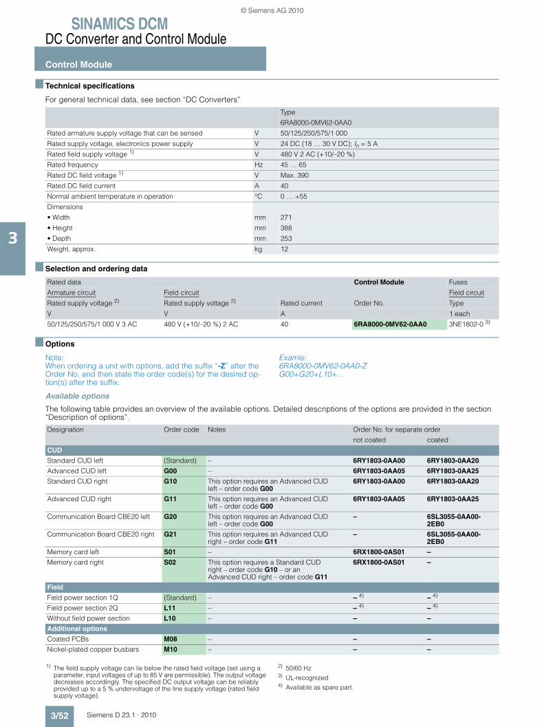
SINAMICS DCMDC Converter and Control Module
Control Module
3/52 Siemens D 23.1 · 2010
3
■ Technical specifications
For general technical data, see section “DC Converters”
■ Selection and ordering data
■ Options
Note: When ordering a unit with options, add the suffix “-Z” after the Order No. and then state the order code(s) for the desired op-tion(s) after the suffix.
Examle: 6RA8000-0MV62-0AA0-Z G00+G20+L10+...
Available options
The following table provides an overview of the available options. Detailed descriptions of the options are provided in the section “Description of options”.
Type
6RA8000-0MV62-0AA0
Rated armature supply voltage that can be sensed V 50/125/250/575/1 000
Rated supply voltage, electronics power supply V 24 DC (18 … 30 V DC); In = 5 A
Rated field supply voltage 1) V 480 V 2 AC (+10/–20 %)
Rated frequency Hz 45 … 65
Rated DC field voltage 1) V Max. 390
Rated DC field current A 40
Normal ambient temperature in operation °C 0 … +55
Dimensions
• Width mm 271
• Height mm 388
• Depth mm 253
Weight, approx. kg 12
Rated data Control Module Fuses
Armature circuit Field circuit Field circuit
Rated supply voltage 2) Rated supply voltage 2) Rated current Order No. Type
V V A 1 each
50/125/250/575/1 000 V 3 AC 480 V (+10/–20 %) 2 AC 40 6RA8000-0MV62-0AA0 3NE1802-0 3)
Designation Order code Notes Order No. for separate order
not coated coated
CUD
Standard CUD left (Standard) – 6RY1803-0AA00 6RY1803-0AA20
Advanced CUD left G00 – 6RY1803-0AA05 6RY1803-0AA25
Standard CUD right G10 This option requires an Advanced CUD left – order code G00
6RY1803-0AA00 6RY1803-0AA20
Advanced CUD right G11 This option requires an Advanced CUD left – order code G00
6RY1803-0AA05 6RY1803-0AA25
Communication Board CBE20 left G20 This option requires an Advanced CUD left – order code G00
– 6SL3055-0AA00-2EB0
Communication Board CBE20 right G21 This option requires an Advanced CUD right – order code G11
– 6SL3055-0AA00-2EB0
Memory card left S01 – 6RX1800-0AS01 –
Memory card right S02 This option requires a Standard CUD right – order code G10 – or an Advanced CUD right – order code G11
6RX1800-0AS01 –
Field
Field power section 1Q (Standard) – – 4) – 4)
Field power section 2Q L11 – – 4) – 4)
Without field power section L10 – – –
Additional options
Coated PCBs M08 – – –
Nickel-plated copper busbars M10 – – –
1) The field supply voltage can lie below the rated field voltage (set using a parameter, input voltages of up to 85 V are permissible). The output voltage decreases accordingly. The specified DC output voltage can be reliably provided up to a 5 % undervoltage of the line supply voltage (rated field supply voltage).
2) 50/60 Hz3) UL-recognized4) Available as spare part.
© Siemens AG 2010

SINAMICS DCMDC Converter and Control Module
Control Module
3/53Siemens D 23.1 · 2010
3
■ Accessories
The SINAMICS DC MASTER Control Module can be split up into several individual modules. These can be mounted separately from one another.
Optional, pre-fabricated cable sets are available to connect the individual modules. This means that the drive system can be quickly but also flexibly adapted to the plant or system configu-ration.
Description Content Connection Order No.
Rear enclosure part including accessories for mounting the firing pulse transformer module and/or fuse monitoring module for a parallel connection
Set of loose parts 6RY1805-0CM00
Screws, stud bolts, and snap-on parts to externally mount module parts
Set of loose parts 6RY1807-0CM00
Pre-fabricated connection setribbon cable:To connect the two cradles when separately mounted
2 x 26-core ribbon cable shielded (3 m long)1 x 10-core ribbon cable shielded (3 m long)1 x 20-core ribbon cable shielded (3 m long)1 x RJ45 patch cable shielded (3 m long)
from X21A, X22A on PC board -A7109-to X21A, X22A on PC board -A7043- from X23B on PC board -A7109- toX23B on PC board -A7118-from XF1 on PC board -A7109- to XF1 on PC board -A7116- from X45 on PC board -A7109-to X45 on PC board -A7117-
6RY1707-0CM01
Pre-fabricated connection setribbon cable:To connect the two cradles when separately mounted
2 x 26-core ribbon cable shielded (10 m long) 1 x 10-core ribbon cable shielded (10 m long) 1 x 20-core ribbon cable shielded (10 m long)1 x RJ45 patch cable shielded (10 m long)
from X21A, X22A on PC board -A7109-to X21A, X22A on PC board -A7043- from X23B on PC board -A7109- toX23B on PC board -A7118- from XF1 on PC board -A7109- to XF1 on PC board -A7116- from X45 on PC board -A7109-to X45 on PC board -A7117-
6RY1807-0CM02
Pre-fabricated connection set for current transformer
2 x 2-core twisted cable(2 m long)
from XB on PC board -A7109- to the current transformers
6RY1707-0CM03 1)
Pre-fabricated connection set for current transformer
2 x 2-core cable shielded (10 m long)
from XB on PC board -A7109- to the current transformers
6RY1707-0CM04 1)
Pre-fabricated connection set for heatsink temperature sensing
1 x 2-core cable shielded (10 m long)
from XT6 on PC board -A7109- to temperature sensor on the heat sink
6RY1707-0CM05
Pre-fabricated connection set for firing pulse cables
Connection set for 12 x 2-core twisted cable (3 m long)
from XIMP11, XIMP12, XIMP13, XIMP14, XIMP15, XIMP16, XIMP21, XIMP22, XIMP23, XIMP24, XIMP25, XIMP26 to the thyristors
6RY1707-0CM06 1)
Pre-fabricated connection set for fuse monitoring
6 x 2-core twisted cable (10 m long)
from XS1_5, XS2_5, XS3_5, XS4_5, XS5_5, XS6_5, XS7_5, XS8_5, XS9_5, XS10_5, XS11_5, XS12_5 or XS1_4, XS2_4, XS3_4, XS4_4, XS5_4, XS6_4, XS7_4, XS8_4, XS9_4, XS10_4, XS11_4, XS12_4 or XS1_3, XS2_3, XS3_3, XS4_3, XS5_3, XS6_3, XS7_3, XS8_3, XS9_3, XS10_3
6RY1807-0CM07
Pre-fabricated connection set for voltage sensing
1 x 3-core twisted cable U-V-W (3 m long)1 x 2-core twisted cable C-D (3 m long)
from XU6, XV6, XW6 or XU5, XV5, XW5 or XU4, XV4, XW4 or XU3, XV3, XW3 or XU2, XV2, XW2 or XU1, XV1, XW1 depending on the voltage (5.6 V, 50 V, 125 V, 250 V, 575 V or 1000 V) to supply XC6, XD6 or XC5, XD5 or XC4, XD4 or XC3, XD3 or XC2, XD2
6RY1807-0CM08
Pre-fabricated connection set forcontrolling the firing pulse transformers
12 x 2-core twisted cable (1 m long)
from XIMP1, XIMP4 or XIMP2, XIMP5 or XIMP3, XIMP6 on PC board -A7043- (side parts) on the firing pulse transformer modules (single boards) with the terminals X11, X12, X13, X14, X15, X16, X21, X22, X23, X24, X25, X26
6RY1707-0CM13 1)
Pre-fabricated connection set forcontrolling the firing pulse transformers
2 x 12-core cable shielded (10 m long)
from XIMP1, XIMP4 and/or XIMP2, XIMP5 and/or XIMP3, XIMP6 on PC board -A7043- to the external firing pulse transformers
6RY1707-0CM10 1)
Pre-fabricated connection set for mounting cradles next to each other
2 x 26-core ribbon cable shielded (10 m long) 1 x 10-core ribbon cable shielded (10 m long) 1 x 20-core ribbon cable shielded (10 m long) 1 x RJ45 patch cable shielded (10 m long)
from X21A, X22A on PC board -A7109-to X21A, X22A on PC board -A7043-from X23B on PC board -A7109- to X23B on PC board -A7118-from XF1 on PC board -A7109- to XF1 on PC board -A7116- from X45 on PC board -A7109-to X45 on PC board -A7117-
6RY1807-0CM11
1) Unchanged when compared to the SIMOREG DC-MASTER Control Modules.
© Siemens AG 2010

SINAMICS DCMDC Converter and Control Module
Control Module
3/54 Siemens D 23.1 · 2010
3
■ Schematics
USS interface
USS interface
Analog outputs
Motortemp.
Ana
log
inpu
tsA
nalo
g in
puts
Main setpoint
BA = electronically switchable bus terminationV/I = electronically switchable voltage/ current input
Supply
Track 1
Track 2
Zero mark
Ser
ial
inte
rfac
e pe
er-to
-pee
r
Pul
se e
ncod
erD
igita
l inp
uts
Dig
ital o
utpu
tsD
igita
l in
puts
/out
puts
M analogM digital
M digital
P24_S (200 mA max.)
Con
trol U
nit C
9804
3-A7
100
and
Con
nect
or B
oard
C98
043-
A712
5
Allo
catio
n B
oard
C98
043-
A712
6
to 2nd CUD (option)
M analog
DRIVE-CLiQ
DRIVE-CLiQ
PROFIBUS
sense
M analog
Memory cardBOP20
operator panel
Option module interface(OMI slot)
Parallel interface (2 x)
AOP30 operator panel (accessory)
or
or
1) Only on Advanced CUD C98043-A71
2) T. X177.12 = /OFF1 T. X177.13 = enable
Armature voltageLine voltage, armature
Fuse OKFan ONElectr. power supplyPower ONE-STOP
Analogtachometer
E-STOP
Armature current
Firing pulses, armature
Fan OK
External fault
Load resistor
Line voltage, fieldFiring pulses, field
Field current actual value
C98043-A7109 power interface
Temperature monitoring
Temperature monitoring
12345678
3334353637383940
4142434445464748
X177
TX+TX-
RX+RX-
M
M
P24
P24
X177
49505152
53545556
X165
X166X126
X100
X101
RS485
RS232
X13
4
1)
1)
1)P10 ± 1% / 10 mAN10 ± 1% / 10 mA
BA
P15
D
D
A
A(300 mA max.)
X178BA
X179
1mA
V/I
V/I
1)
2)
XP24 V
XT1
ES/P24
M M
XM
XS
1 - +
M N P
X108
M
M
8- 270
V
24 V DC
106
105
104
103
1
U#
U#
U#
U#
U#
U#
U#
91011121314
15
16
17
18
19
20
21
22
32
2324
252627
282930
31
© Siemens AG 2010

SINAMICS DCMDC Converter and Control Module
Control Module
3/55Siemens D 23.1 · 2010
3
■ Schematics (continued)
δ
G_D023_EN_00069
C98043-A7118 fuse monitoring
C98043-A7117 voltage sensing
Fuse
s
Line voltage,armature
Armaturevoltage
Firing pulses, field
Line voltage, field
Field module
Field current actual value
Externalpowersection
Analog tachometer
TerminalsXT1(103, 104)
Pulse encoder
TerminalsX177 (41...48)
Fanmoni-toring
Voltage sensing from module C98043-A7043 (firing pulse transformer) or directly from the power section
Externalfault
Current transformers
Fan monitoring
Temperature sensor
External current actual value
3. Current transformer
Analoginput CUD
1D1(1C1)
1C1(1D1)
~M
4W1
4V1
4U1
1W1
1U1
X23B
3 AC 50 ... 60 Hz, 400 V
3 AC 50 ... 60 Hz 20 ... 1 000 V
X45
3U1 3W1
XS1_5 XS1_1XS1_4125 V 250 V 575 V 1 000 V50 V
XS1_2XS1_3. . . . . .. . . . . .. . . . . .
12
1
VU
VW ~~
==
~~
5.6 V 50 V125 V 250 V 575 V 1 000 VXU1XU2XU3XU4XU5XU6 UXV1XV2XV3XV4XV5XV6 V
W1C11D1
C98043-A7043
XIMP_1...3
C98043-A7043
XIMP11...16
X12_1(W)X14_1(U)X16_1(V)
X15_1(1C1)
X21A
X22A
X21PAR X22PAR
XIMP_4...6
XIMP21...26
X25_1(1D1)
X11... 16X21... 26
3C
3DShunt
XW1XW2XW3XW4XW5XW6XC1XC2XC3XC4XC5XC6XD1XD2XD3XD4XD5XD6
XS12_5 XS12_1XS12_4 XS12_2XS12_3
K1
K3
M
G1
2C98043-A7116
-
+U
#
U#
K1
XR1
120
109
121 K2
110
XL1
X23B
X45
X_I_IST
X21A
X22A
XT5
XT6
122123124125
XL2
XF1
1
13
3
XB1XB2XB3XB4
XB5XB6XB7XB8
1 AC 50 ... 60 Hz, 230 V
1V1
1)
1)
K2
© Siemens AG 2010
SINAMICS DCMDC Converter and Control Module
Notes
3/56 Siemens D 23.1 · 2010
3
© Siemens AG 2010
Siemens D 23.1 · 2010
44/2 AOP30 Advanced Operator Panel 4/2 Overview4/3 Function4/3 Selection and ordering data
4/4 SMC30 Sensor Module Cabinet-Mounted
4/4 Overview4/4 Design4/4 Integration4/4 Technical specifications4/4 Selection and ordering data4/4 • SMC30 Sensor Module Cabinet-
Mounted 4/4 • DRIVE-CLiQ cables
4/5 TM15 Terminal Module 4/5 Overview4/5 Design4/6 Integration4/7 Technical specifications4/7 Selection and ordering data4/7 • TM15 Terminal Module 4/7 • DRIVE-CLiQ cables
4/8 TM31 Terminal Module 4/8 Overview4/8 Design4/9 Integration4/10 Technical specifications4/10 Selection and ordering data4/10 • TM31 Terminal Module 4/10 • DRIVE-CLiQ cables
4/11 Mounting kit to upgrade to IP204/11 Overview4/11 Selection and ordering data
4/12 Line fuses4/12 Overview4/12 Selection and ordering data4/12 • Fuses for the field circuit4/12 • Fuses for the armature circuit
4/16 Commutating reactors4/16 Overview4/17 Selection and ordering data
4/19 Circuit-breakers and contactors4/19 Overview4/19 • Selection criteria
4/19 Radio interference suppression filters4/19 Overview4/19 • List of the recommended radio
interference suppression filters from EPCOS
4/20 • List of the recommended radio interference suppression filters from Siemens
4/20 Technical specifications
4/21 SICROWBAR AC overvoltage protection
4/21 Application4/21 Design4/21 Mode of operation4/21 Configuration4/22 Technical specifications4/23 Selection and ordering data4/23 Accessories
4/24 SICROWBAR DC overvoltage protection
4/24 Application4/24 Design4/24 Mode of operation4/25 Configuration4/26 Technical specifications4/27 Selection and ordering data4/27 Accessories4/27 Options
4/28 SIMOREG CCP4/28 Overview4/28 Benefits4/28 Design4/28 Function4/29 Integration4/30 Technical specifications4/31 Selection and ordering data4/31 Accessories4/32 Schematics
Accessories and supplementary components
© Siemens AG 2010
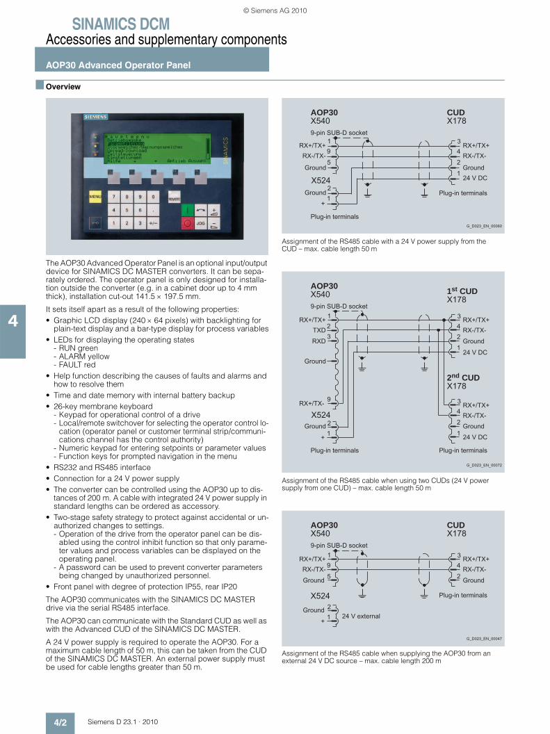
SINAMICS DCMAccessories and supplementary components
AOP30 Advanced Operator Panel
4/2 Siemens D 23.1 · 2010
4
■ Overview
The AOP30 Advanced Operator Panel is an optional input/output device for SINAMICS DC MASTER converters. It can be sepa-rately ordered. The operator panel is only designed for installa-tion outside the converter (e.g. in a cabinet door up to 4 mm thick), installation cut-out 141.5 × 197.5 mm.
It sets itself apart as a result of the following properties:• Graphic LCD display (240 × 64 pixels) with backlighting for
plain-text display and a bar-type display for process variables• LEDs for displaying the operating states
- RUN green- ALARM yellow- FAULT red
• Help function describing the causes of faults and alarms and how to resolve them
• Time and date memory with internal battery backup• 26-key membrane keyboard
- Keypad for operational control of a drive- Local/remote switchover for selecting the operator control lo-
cation (operator panel or customer terminal strip/communi-cations channel has the control authority)
- Numeric keypad for entering setpoints or parameter values- Function keys for prompted navigation in the menu
• RS232 and RS485 interface• Connection for a 24 V power supply• The converter can be controlled using the AOP30 up to dis-
tances of 200 m. A cable with integrated 24 V power supply in standard lengths can be ordered as accessory.
• Two-stage safety strategy to protect against accidental or un-authorized changes to settings. - Operation of the drive from the operator panel can be dis-
abled using the control inhibit function so that only parame-ter values and process variables can be displayed on the operating panel.
- A password can be used to prevent converter parameters being changed by unauthorized personnel.
• Front panel with degree of protection IP55, rear IP20
The AOP30 communicates with the SINAMICS DC MASTER drive via the serial RS485 interface.
The AOP30 can communicate with the Standard CUD as well as with the Advanced CUD of the SINAMICS DC MASTER.
A 24 V power supply is required to operate the AOP30. For a maximum cable length of 50 m, this can be taken from the CUD of the SINAMICS DC MASTER. An external power supply must be used for cable lengths greater than 50 m.
Assignment of the RS485 cable with a 24 V power supply from the CUD – max. cable length 50 m
Assignment of the RS485 cable when using two CUDs (24 V power supply from one CUD) – max. cable length 50 m
Assignment of the RS485 cable when supplying the AOP30 from an external 24 V DC source – max. cable length 200 m
21
1
19
5 2
43
X524
RX+/TX+RX-/TX-
RX+/TX+RX-/TX-
+
9-pin SUB-D socket
Plug-in terminals
Plug-in terminals
24 V DCGroundGround
Ground
G_D023_EN_00060
CUDX178
AOP30X540
RX+/TX+
RX+/TX+RX-/TX-
RX+/TX+TXD
RXD
1
2
439
+
21
1
123 2
43
RX-/TX-
RX+/TX-
9-pin SUB-D socket
Plug-in terminals Plug-in terminals
24 V DC
Ground
24 V DC
X524Ground
Ground
Ground
G_D023_EN_00072
2nd CUDX178
1st CUDX178
AOP30X540
RX+/TX+RX-/TX-
RX+/TX+RX-/TX-
+
21
19
5 2
43
9-pin SUB-D socket
Plug-in terminals
24 V external
GroundGround
Ground
G_D023_EN_00047
CUDX178
AOP30X540
X524
© Siemens AG 2010
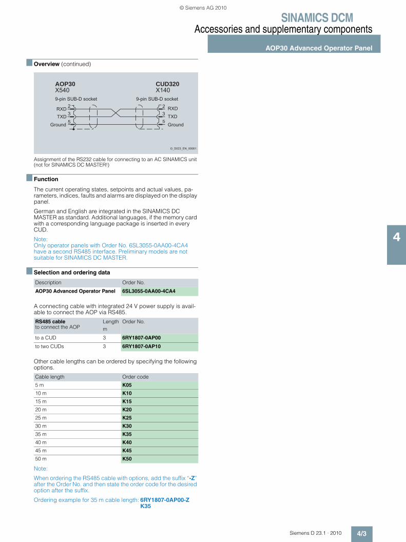
SINAMICS DCMAccessories and supplementary components
AOP30 Advanced Operator Panel
4/3Siemens D 23.1 · 2010
4
■ Overview (continued)
Assignment of the RS232 cable for connecting to an AC SINAMICS unit (not for SINAMICS DC MASTER!)
■ Function
The current operating states, setpoints and actual values, pa-rameters, indices, faults and alarms are displayed on the display panel.
German and English are integrated in the SINAMICS DC MASTER as standard. Additional languages, if the memory card with a corresponding language package is inserted in every CUD.
Note: Only operator panels with Order No. 6SL3055-0AA00-4CA4 have a second RS485 interface. Preliminary models are not suitable for SINAMICS DC MASTER.
■ Selection and ordering data
A connecting cable with integrated 24 V power supply is avail-able to connect the AOP via RS485.
Other cable lengths can be ordered by specifying the following options.
Note:
When ordering the RS485 cable with options, add the suffix “-Z” after the Order No. and then state the order code for the desired option after the suffix.
Ordering example for 35 m cable length: 6RY1807-0AP00-Z K35
Description Order No.
AOP30 Advanced Operator Panel 6SL3055-0AA00-4CA4
RS485 cable to connect the AOP
Lengthm
Order No.
to a CUD 3 6RY1807-0AP00
to two CUDs 3 6RY1807-0AP10
Cable length Order code
5 m K05
10 m K10
15 m K15
20 m K20
25 m K25
30 m K30
35 m K35
40 m K40
45 m K45
50 m K50
RXDTXD TXD
RXD23
5 5
32
9-pin SUB-D socket 9-pin SUB-D socket
CUD320X140
Ground Ground
G_D023_EN_00061
AOP30X540
© Siemens AG 2010

SINAMICS DCMAccessories and supplementary components
SMC30 Sensor Module Cabinet-Mounted
4/4 Siemens D 23.1 · 2010
4
■ Overview
Every CUD (both Standard CUD as well as also Advanced CUD) can evaluate the signals of an incremental encoder. For applica-tions where more than one encoder must be evaluated, either a second CUD and/or the SMC30 Sensor Module Cabinet-Mounted can be used. The SMC30 can be used to evaluate SSI encoders with incre-mental signals, which for instance, are used for positioning functions.
Encoders, which have a DRIVE-CLiQ interface, cannot be eval-uated at the SINAMICS DC MASTER or at the SMC30. These encoders are usually not used in the DC drive technology.
The following encoder signals can be evaluated:• Incremental encoders TTL/HTL with and without broken cable
detection (broken cable detection is only available with bipo-lar signals)
• SSI encoder with TTL/HTL incremental signals• SSI encoder without incremental signals
The motor temperature input, available on the SMC30, is not evaluated for SINAMICS DC MASTER. A motor temperature sen-sor can be evaluated using the temperature measurement input provided on each CUD.
■ Design
The SMC30 Sensor Module Cabinet-Mounted features the following interfaces as standard:• 1 DRIVE-CLiQ interface• 1 encoder connection via Sub-D connector or terminals• 1 connection for the electronics power supply via the 24 V DC
power supply connector• 1 PE/protective conductor connection
The status of the SMC30 Sensor Module Cabinet-Mounted is in-dicated using a multi-color LED.
The SMC30 Sensor Module Cabinet-Mounted can be snapped on a TH mounting rail in accordance with EN 60715 (IEC 60715).
The maximum encoder cable length between SMC30 modules and encoders is 100 m. For HTL encoders, this length can be in-creased to 300 m if the A+/A- and B+/B- signals are evaluated and the power supply cable has a minimum cross section of 0.5 mm2.
The signal cable shield can be connected to the SMC30 Sensor Module Cabinet-Mounted via a shield connection terminal, e.g. Phoenix Contact type SK8 or Weidmüller type KLBÜ CO 1.
■ Integration
The SMC30 Sensor Module Cabinet-Mounted communicates with the Advanced CUD via DRIVE-CLiQ. One SMC30 can be connected to each Advanced CUD.
■ Technical specifications
■ Selection and ordering data
Note: The maximum permissible encoder currents should be carefully observed. The capacitive recharging currents increase in the connecting cable between the encoder and converter due to long cable lengths and high output frequencies. This can cause the output driver of the encoder to be overloaded and/or result in incorrect evaluation of the encoder signals. This is the reason that the encoder manufacturer’s instructions must be carefully observed.
SMC30 Sensor Module Cabinet-Mounted
Current consumption, max.at 24 V DC, not taking the encoder into account
0.2 A
• Conductor cross-section, max. 2.5 mm2
• Fuse protection, max. 20 A
Power loss < 10 W
Encoders that can be evaluated • Incremental encoder TTL/HTL• SSI encoder with TTL/HTL in-
cremental signals• SSI encoder without incremen-
tal signals
• Encoder supply 24 V DC/0.35 A or5 V DC/0.35 A
• Encoder frequency, max. 300 kHz
• SSI baud rate 100 … 250 kBaud
• Limiting frequency 300 kHz
• Resolution absolute position SSI 30 bits
• Cable length, max.- TTL encoder 100 m (only bipolar signals
permitted)1)
- HTL encoder 100 m for unipolar signals300 m for bipolar signals1)
- SSI encoder 100 m
PE connection M4 screw
Dimensions
• Width 30 mm
• Height 150 mm
• Depth 111 mm
Weight, approx. 0.45 kg
Approvals cULus (File No.: E164110)
Description Order No.
SMC30 Sensor Module Cabinet-Mounted(without DRIVE-CLiQ cable)
6SL3055-0AA00-5CA2
1) Twisted pair and shielded signal cables.
© Siemens AG 2010

SINAMICS DCMAccessories and supplementary components
SMC30 Sensor Module Cabinet-Mounted
4/5Siemens D 23.1 · 2010
4
■ Selection and ordering data (continued)
DRIVE-CLiQ cables
■ Overview
The number of available digital inputs and outputs within a drive system can be expanded with the TM15 Terminal Module.
■ Design
The following are located on the TM15 Terminal Module:• 24 bidirectional digital inputs/outputs (isolation in 3 groups
with 8 channels each)• 24 green status LEDs for indicating the logical signal status of
the relevant terminal• 2 DRIVE-CLiQ sockets• 1 connection for the electronics power supply via the 24 V DC
power supply connector• 1 PE/protective conductor connection
The TM15 Terminal Module can be snapped on a TH 35 mount-ing rail in accordance with EN 60715 (IEC 60715).
The signal cable shield can be connected to the TM15 Terminal Module via a shield connection terminal, e.g. Phoenix Contact type SK8 or Weidmüller type KLBÜ CO 1. The shield connection terminal must not be used for strain relief.
The status of the TM15 Terminal Module is indicated via a multi-color LED.
Description Length Order No.
m
Pre-fabricated DRIVE-CLiQ cableDegree of protection of connector IP20/IP20
0.11 6SL3060-4AB00-0AA0
0.16 6SL3060-4AD00-0AA0
0.21 6SL3060-4AF00-0AA0
0.26 6SL3060-4AH00-0AA0
0.36 6SL3060-4AM00-0AA0
0.60 6SL3060-4AU00-0AA0
0.95 6SL3060-4AA10-0AA0
1.20 6SL3060-4AW00-0AA0
1.45 6SL3060-4AF10-0AA0
2.80 6SL3060-4AJ20-0AA0
5.00 6SL3060-4AA50-0AA0
TM15 Terminal Module
© Siemens AG 2010

SINAMICS DCMAccessories and supplementary components
TM15 Terminal Module
4/6 Siemens D 23.1 · 2010
4
■ Integration
The TM15 Terminal Module communicates with the Advanced CUD via DRIVE-CLiQ. Further, TM15 can also be used with the
CU310 and CU320 Control Units and a SIMOTION D Control Unit.
Connection example of a TM15 Terminal Module
X501 X500
+ 24 V
M
X524
M
+
M
+
M
M
+
M
+
1
0
Terminal Module TM15
L1+
M1
X520
DI/DO 0
1
2
3
4
5
6
DI/DO 1
DI/DO 3
L1+
DI/DO 2
1) DI/DO 4
7
8
9
10
DI/DO 5
DI/DO 7
DI/DO 6
M1
L2+
M2
X521
DI/DO 8
1
2
3
4
5
6
DI/DO 9
DI/DO 11
L2+
DI/DO 10
1) DI/DO 12
7
8
9
10
DI/DO 13
DI/DO 15
DI/DO 14
M2
L3+
M3
X522
DI/DO 16
1
2
3
4
5
6
DI/DO 17
DI/DO 19
L3+
DI/DO 18
1) DI/DO 20
7
8
9
10
DI/DO 21
DI/DO 23
DI/DO 22
M3
1) Can be parameterized individually as input or output.
G_D211_EN_00040
ext. 24 V
DR
IVE
-CLi
Q s
ocke
t
DR
IVE
-CLi
Q s
ocke
t
M
M
M
© Siemens AG 2010
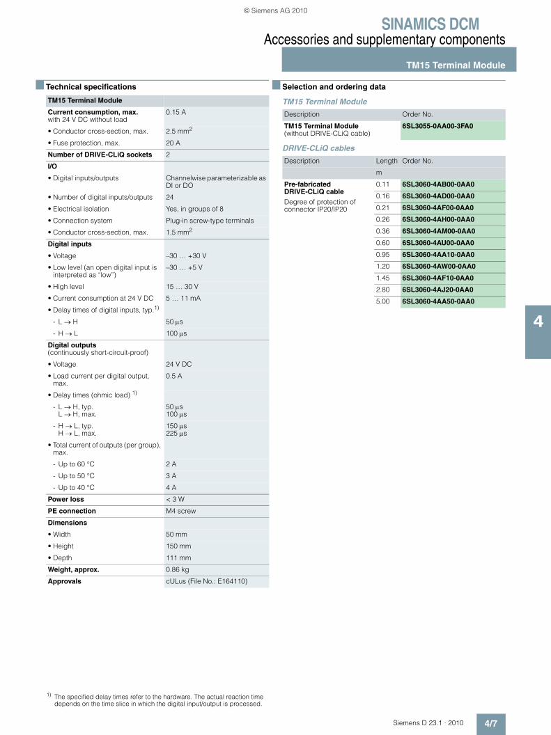
SINAMICS DCMAccessories and supplementary components
TM15 Terminal Module
4/7Siemens D 23.1 · 2010
4
■ Technical specifications
■ Selection and ordering data
TM15 Terminal Module
DRIVE-CLiQ cables
TM15 Terminal Module
Current consumption, max.with 24 V DC without load
0.15 A
• Conductor cross-section, max. 2.5 mm2
• Fuse protection, max. 20 A
Number of DRIVE-CLiQ sockets 2
I/O
• Digital inputs/outputs Channelwise parameterizable as DI or DO
• Number of digital inputs/outputs 24
• Electrical isolation Yes, in groups of 8
• Connection system Plug-in screw-type terminals
• Conductor cross-section, max. 1.5 mm2
Digital inputs
• Voltage –30 … +30 V
• Low level (an open digital input is interpreted as “low”)
–30 … +5 V
• High level 15 … 30 V
• Current consumption at 24 V DC 5 … 11 mA
• Delay times of digital inputs, typ.1)
- L → H 50 μs
- H → L 100 μs
Digital outputs(continuously short-circuit-proof)
• Voltage 24 V DC
• Load current per digital output, max.
0.5 A
• Delay times (ohmic load) 1)
- L → H, typ.L → H, max.
50 μs100 μs
- H → L, typ.H → L, max.
150 μs225 μs
• Total current of outputs (per group), max.
- Up to 60 °C 2 A
- Up to 50 °C 3 A
- Up to 40 °C 4 A
Power loss < 3 W
PE connection M4 screw
Dimensions
• Width 50 mm
• Height 150 mm
• Depth 111 mm
Weight, approx. 0.86 kg
Approvals cULus (File No.: E164110)
Description Order No.
TM15 Terminal Module(without DRIVE-CLiQ cable)
6SL3055-0AA00-3FA0
Description Length Order No.
m
Pre-fabricated DRIVE-CLiQ cableDegree of protection of connector IP20/IP20
0.11 6SL3060-4AB00-0AA0
0.16 6SL3060-4AD00-0AA0
0.21 6SL3060-4AF00-0AA0
0.26 6SL3060-4AH00-0AA0
0.36 6SL3060-4AM00-0AA0
0.60 6SL3060-4AU00-0AA0
0.95 6SL3060-4AA10-0AA0
1.20 6SL3060-4AW00-0AA0
1.45 6SL3060-4AF10-0AA0
2.80 6SL3060-4AJ20-0AA0
5.00 6SL3060-4AA50-0AA0
1) The specified delay times refer to the hardware. The actual reaction time depends on the time slice in which the digital input/output is processed.
© Siemens AG 2010
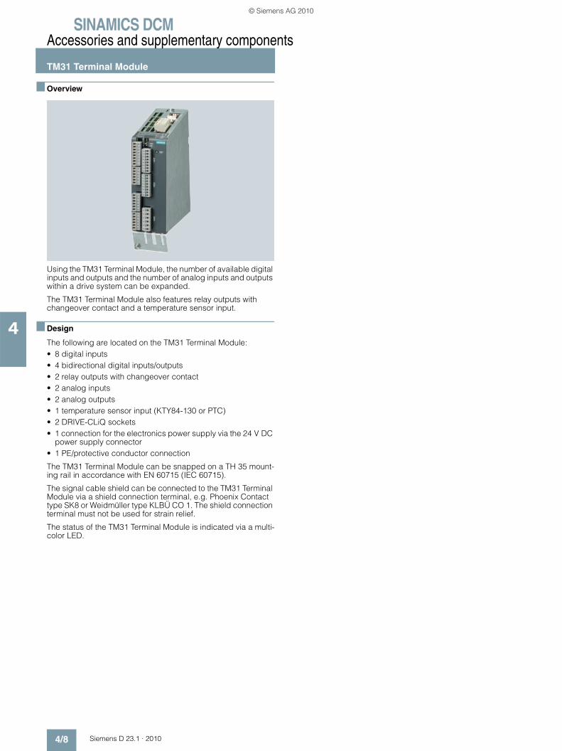
SINAMICS DCMAccessories and supplementary components
TM31 Terminal Module
4/8 Siemens D 23.1 · 2010
4
■ Overview
Using the TM31 Terminal Module, the number of available digital inputs and outputs and the number of analog inputs and outputs within a drive system can be expanded.
The TM31 Terminal Module also features relay outputs with changeover contact and a temperature sensor input.
■ Design
The following are located on the TM31 Terminal Module:• 8 digital inputs• 4 bidirectional digital inputs/outputs• 2 relay outputs with changeover contact• 2 analog inputs• 2 analog outputs• 1 temperature sensor input (KTY84-130 or PTC)• 2 DRIVE-CLiQ sockets• 1 connection for the electronics power supply via the 24 V DC
power supply connector• 1 PE/protective conductor connection
The TM31 Terminal Module can be snapped on a TH 35 mount-ing rail in accordance with EN 60715 (IEC 60715).
The signal cable shield can be connected to the TM31 Terminal Module via a shield connection terminal, e.g. Phoenix Contact type SK8 or Weidmüller type KLBÜ CO 1. The shield connection terminal must not be used for strain relief.
The status of the TM31 Terminal Module is indicated via a multi-color LED.
© Siemens AG 2010

SINAMICS DCMAccessories and supplementary components
TM31 Terminal Module
4/9Siemens D 23.1 · 2010
4
■ Integration
The TM31 Terminal Module communicates with the Advanced CUD via DRIVE-CLiQ.
Connection example of a TM31 Terminal Module
X501X500
4
3
2
1
5
6M
X520
+ 24 V
4
3
2
1
5
6
7
8
X540
4
3
2
1
5
6 M
X530
1)
AI 0+
4
3
2
1
AI 0-
AI 1-
AI 1+
5P10
6M
X521
7N10
M8
AO 0V+
4
3
2
1
AO 0-
AO 1V+
AO 0C+
5AO 1-
6AO 1C+
X522
7+Temp
-Temp 8
V
V
4
3
2
1
DO 0
5DO 1
6
X542
+ 24 V
M
X524
M
+
M
+
M
M
+
M
+
X541
DI/DO 8
1
2
3
4
5
6
DI/DO 9
DI/DO 11
+
DI/DO 10
M
2)
3)
A
A
Terminal ModuleTM31
DI 0
DI 1
DI 3
DI 2
M 1
DI 4
DI 5
DI 7
DI 6
M 2
M
M
M
M
M
M
M
M
1)
+
-
+
-
+
-
+
-
4)
+
-
+
-
G_D212_EN_00029e
+
-
ext.24 V
DR
IVE
-CLI
Q s
ocke
t 0
DR
IVE
-CLI
Q s
ocke
t 1
1) The jumpers must be inserted in this circuit example.2) Can be parameterized individually as current source.3) Can be parameterized individually as output.4) Current limitation can be parameterized (0.1 A or 1 A)
+
-
IC for current limitation
0.15 A
© Siemens AG 2010

SINAMICS DCMAccessories and supplementary components
TM31 Terminal Module
4/10 Siemens D 23.1 · 2010
4
■ Technical specifications
■ Selection and ordering data DRIVE-CLiQ cables
TM31 Terminal Module
Current consumption, max.At 24 V DC without taking into account the digital outputs and DRIVE-CLiQ supply
0.2 A
• Conductor cross-section, max. 2.5 mm2
• Fuse protection, max. 20 A
Digital inputs
• Voltage –3 … +30 V
• Low level (an open digital input is interpreted as “low”)
–3 … +5 V
• High level 15 … 30 V
• Current consumption at 24 V DC, typ.
10 mA
• Delay times of digital inputs 1), approx.
- L → H 50 μs
- H → L 100 μs
• Conductor cross-section, max. 1.5 mm2
Digital outputs(continuously short-circuit-proof)
• Voltage 24 V DC
• Total current of digital outputs, max. 1 000 mA
• Delay times of digital outputs 1)
- typ. 150 μs with 0.5 A resistive load
- max. 500 μs
• Conductor cross-section, max. 1.5 mm2
Analog inputs
• As voltage input
- Voltage range -10 … +10 V
- Internal resistance Ri 100 kΩ
• As current input
- Current range 4 … 20 mA, –20 … +20 mA, 0 … 20 mA
- Internal resistance Ri 250 Ω
- Resolution 2) 11 bits + sign
• Conductor cross-section, max. 1.5 mm2
TM31 Terminal Module
Analog outputs(continuously short-circuit-proof)
• Voltage range -10 … +10 V
• Load current, max. –3 … +3 mA
• Current range 4 … 20 mA, –20 … +20 mA, 0 … 20 mA
• Load resistance, max. 500 Ω for outputs in the range –20 … +20 mA
• Resolution 11 bits + sign
• Conductor cross-section, max. 1.5 mm2
Relay outputs(changeover contacts)
• Load current, max. 8 A
• Switching voltage, max. 250 V AC, 30 V DC
• Switching capacity, max.
- At 250 V AC 2 000 VA (cos ϕ = 1)750 VA (cos ϕ = 0.4)
- At 30 V DC 240 W (resistive load)
• Required minimum current 100 mA
• Conductor cross-section, max. 2.5 mm2
Power loss < 10 W
PE connection M4 screw
Dimensions
• Width 50 mm
• Height 150 mm
• Depth 111 mm
Weight, approx. 0.87 kg
Approvals cULus (File No.: 164110)
Description Order No.
TM31 Terminal Module(without DRIVE-CLiQ cable)
6SL3055-0AA00-3AA1
1) The specified delay times refer to the hardware. The actual reaction time depends on the time slice in which the digital input is processed.
2) If the analog input is to be operated in the signal processing sense with a continuously variable input voltage, the sampling frequency fa = 1/ttime slicemust be at least twice the value of the highest signal frequency fmax.
Description Length Order No.
m
Pre-fabricated DRIVE-CLiQ cableDegree of protection of connector IP20/IP20
0.11 6SL3060-4AB00-0AA0
0.16 6SL3060-4AD00-0AA0
0.21 6SL3060-4AF00-0AA0
0.26 6SL3060-4AH00-0AA0
0.36 6SL3060-4AM00-0AA0
0.60 6SL3060-4AU00-0AA0
0.95 6SL3060-4AA10-0AA0
1.20 6SL3060-4AW00-0AA0
1.45 6SL3060-4AF10-0AA0
2.80 6SL3060-4AJ20-0AA0
5.00 6SL3060-4AA50-0AA0
© Siemens AG 2010

SINAMICS DCMAccessories and supplementary components
Mounting kit to upgrade to IP20
4/11Siemens D 23.1 · 2010
4
■ Overview
With a mounting kit, it is possible to increase the degree of protection of SINAMICS DC MASTER from IP00 up to IP20.
■ Selection and ordering data
For units up to 850 A, there is a suitable mounting kit to increase the degree of protection; this can be ordered using the following order numbers.
Mounting kit to upgrade to IP20
Description Order No.
for units from 15 to 30 A 6RX1800-0MA00
for units from 60 to 280 A 6RX1800-0MA01
for units from 400 to 600 A 6RX1800-0MA02
for units from 720 to 850 A 6RX1800-0MA03
© Siemens AG 2010
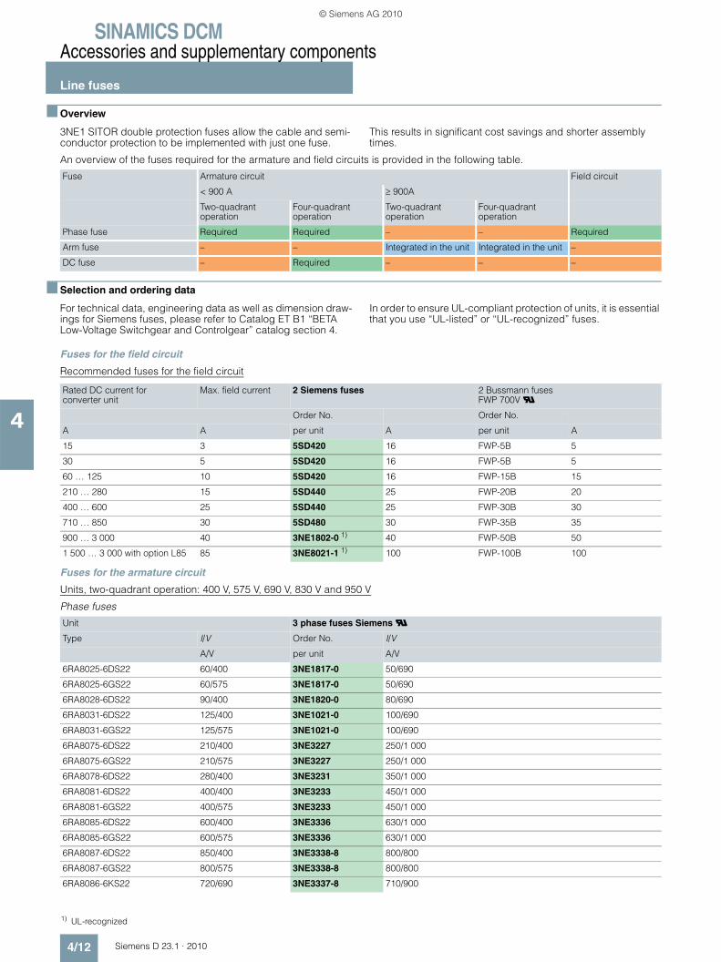
SINAMICS DCMAccessories and supplementary components
Line fuses
4/12 Siemens D 23.1 · 2010
4
■ Overview
3NE1 SITOR double protection fuses allow the cable and semi-conductor protection to be implemented with just one fuse.
This results in significant cost savings and shorter assembly times.
An overview of the fuses required for the armature and field circuits is provided in the following table.
■ Selection and ordering data
For technical data, engineering data as well as dimension draw-ings for Siemens fuses, please refer to Catalog ET B1 “BETA Low-Voltage Switchgear and Controlgear” catalog section 4.
In order to ensure UL-compliant protection of units, it is essential that you use “UL-listed” or “UL-recognized” fuses.
Fuses for the field circuit
Recommended fuses for the field circuit
Fuses for the armature circuit
Units, two-quadrant operation: 400 V, 575 V, 690 V, 830 V and 950 V
Phase fuses
Fuse Armature circuit Field circuit
< 900 A ≥ 900A
Two-quadrant operation
Four-quadrant operation
Two-quadrant operation
Four-quadrant operation
Phase fuse Required Required – – Required
Arm fuse – – Integrated in the unit Integrated in the unit –
DC fuse – Required – – –
Rated DC current for converter unit
Max. field current 2 Siemens fuses 2 Bussmann fusesFWP 700V U
Order No. Order No.
A A per unit A per unit A
15 3 5SD420 16 FWP-5B 5
30 5 5SD420 16 FWP-5B 5
60 … 125 10 5SD420 16 FWP-15B 15
210 … 280 15 5SD440 25 FWP-20B 20
400 … 600 25 5SD440 25 FWP-30B 30
710 … 850 30 5SD480 30 FWP-35B 35
900 … 3 000 40 3NE1802-0 1) 40 FWP-50B 50
1 500 … 3 000 with option L85 85 3NE8021-1 1) 100 FWP-100B 100
Unit 3 phase fuses Siemens U
Type I/V Order No. I/V
A/V per unit A/V
6RA8025-6DS22 60/400 3NE1817-0 50/690
6RA8025-6GS22 60/575 3NE1817-0 50/690
6RA8028-6DS22 90/400 3NE1820-0 80/690
6RA8031-6DS22 125/400 3NE1021-0 100/690
6RA8031-6GS22 125/575 3NE1021-0 100/690
6RA8075-6DS22 210/400 3NE3227 250/1 000
6RA8075-6GS22 210/575 3NE3227 250/1 000
6RA8078-6DS22 280/400 3NE3231 350/1 000
6RA8081-6DS22 400/400 3NE3233 450/1 000
6RA8081-6GS22 400/575 3NE3233 450/1 000
6RA8085-6DS22 600/400 3NE3336 630/1 000
6RA8085-6GS22 600/575 3NE3336 630/1 000
6RA8087-6DS22 850/400 3NE3338-8 800/800
6RA8087-6GS22 800/575 3NE3338-8 800/800
6RA8086-6KS22 720/690 3NE3337-8 710/900
1) UL-recognized
© Siemens AG 2010

SINAMICS DCMAccessories and supplementary components
Line fuses
4/13Siemens D 23.1 · 2010
4
■ Selection and ordering data (continued)
Arm fuses
Note: The arm fuses are included in the unit. No external semiconductor fuses are required.
Units, two-quadrant operation: 480 V
Phase fuses
Arm fuses
Note: The arm fuses are included in the unit. No external semiconductor fuses are required.
Unit Arm fuses Siemens U
Type I/V Fuses Order No. I/V
A/V per unit A/V
6RA8091-6DS22 1 200/400 6 3NE3338-8 800/800
6RA8090-6GS22 1 100/575 6 3NE3338-8 800/800
6RA8090-6KS22 1 000/690 6 3NE3337-8 710/900
6RA8088-6LS22 950/830 6 3NE3337-8 710/900
6RA8093-4DS22 1 600/400 6 6RY1702-0BA02 1 000/660
6RA8093-4GS22 1 600/575 6 6RY1702-0BA02 1 000/660
6RA8093-4KS22 1 500/690 6 6RY1702-0BA03 1 000/1 000
6RA8093-4LS22 1 500/830 6 6RY1702-0BA03 1 000/1 000
6RA8095-4DS22 2 000/400 6 6RY1702-0BA01 1 250/660
6RA8095-4GS22 2 000/575 6 6RY1702-0BA01 1 250/660
6RA8095-4KS22 2 000/690 12 6RY1702-0BA04 630/1 000
6RA8095-4LS22 1 900/830 12 6RY1702-0BA04 630/1 000
6RA8096-4GS22 2 200/575 6 6RY1702-0BA05 1 500/660
6RA8096-4MS22 2 200/950 12 6RY1702-0BA07 800/1 250
6RA8097-4KS22 2 600/690 12 6RY1702-0BA08 1 000/1 000
6RA8097-4GS22 2 800/575 12 6RY1702-0BA08 1 000/1 000
6RA8098-4DS22 3 000/400 12 6RY1702-0BA08 1 000/1 000
Unit 3 phase fuses Siemens U
3 phase fuses Bussmann U
3 phase fuses Bussmann U 1)
Type I/V Order No. I/V Order No. I/V Order No. I/V
A/V per unit A/V per unit A/V per unit A/V
6RA8025-6FS22 60/480 3NE1817-0 50/690 170M1565 63/660 FWH-60B 60/500
6RA8028-6FS22 90/480 3NE1820-0 80/690 170M1567 100/660 FWH-100B 100/500
6RA8031-6FS22 125/480 3NE1021-0 100/690 170M1568 125/660 FWH-125B 125/500
6RA8075-6FS22 210/480 3NE3227 250/1 000 170M3166 250/660 FWH-225A 225/500
6RA8078-6FS22 280/480 3NE3231 350/1 000 170M3167 315/660 FWH-275A 275/500
6RA8082-6FS22 450/480 3NE3233 450/1 000 170M3170 450/660 FWH-450A 450/500
6RA8085-6FS22 600/480 3NE3336 630/1 000 170M4167 700/660 FWH-600A 600/500
6RA8087-6FS22 850/480 3NE3338-8 800/800 170M5165 900/660 FWH-800A 800/500
Unit Arm fuses Siemens U
Type I/V Fuses Order No. I/V
A/V per unit A/V
6RA8091-6FS22 1 200/480 6 3NE3338-8 800/800
1) FWH-... fuses are not mechanically compatible with 3NE or 170M fuses.
© Siemens AG 2010

SINAMICS DCMAccessories and supplementary components
Line fuses
4/14 Siemens D 23.1 · 2010
4
■ Selection and ordering data (continued)
Units, four-quadrant operation: 400 V, 575 V, 690 V, 830 V and 950 V
Phase fuses, DC fuse
Arm fuses
Note: The arm fuses are included in the unit. No external semiconductor fuses are required.
Unit 3 phase fuses Siemens U 1 DC fuse Siemens U
Type I/V Order No. I/V Order No. I/V
A/V per unit A/V per unit A/V
6RA8013-6DV62 15/400 3NE1814-0 20/690 3NE1814-0 20/690
6RA8018-6DV62 30/400 3NE8003-1 35/690 3NE4102 40/1 000
6RA8025-6DV62 60/400 3NE1817-0 50/690 3NE4120 80/1 000
6RA8025-6GV62 60/575 3NE1817-0 50/690 3NE4120 80/1 000
6RA8028-6DV62 90/400 3NE1820-0 80/690 3NE4122 125/1 000
6RA8031-6DV62 125/400 3NE1021-0 100/690 3NE4124 160/1 000
6RA8031-6GV62 125/575 3NE1021-0 100/690 3NE4124 160/1 000
6RA8075-6DV62 210/400 3NE3227 250/1 000 3NE3227 250/1 000
6RA8075-6GV62 210/575 3NE3227 250/1 000 3NE3227 250/1 000
6RA8078-6DV62 280/400 3NE3231 350/1 000 3NE3231 350/1 000
6RA8081-6DV62 400/400 3NE3233 450/1 000 3NE3233 450/1 000
6RA8081-6GV62 400/575 3NE3233 450/1 000 3NE3233 450/1 000
6RA8085-6DV62 600/400 3NE3336 630/1 000 3NE3336 630/1 000
6RA8085-6GV62 600/575 3NE3336 630/1 000 3NE3336 630/1 000
6RA8087-6DV62 850/400 3NE3338-8 800/800 3NE3334-0B 1) 500/1 000
6RA8087-6GV62 850/575 3NE3338-8 800/800 3NE3334-0B 1) 500/1 000
6RA8086-6KV62 760/690 3NE3337-8 710/900 3NE3334-0B 1) 500/1 000
Unit Arm fuses Siemens U
Type I/V Fuses Order No. I/V
A/V per unit A/V
6RA8091-6DV62 1 200/400 6 3NE3338-8 800/800
6RA8090-6GV62 1 100/575 6 3NE3338-8 800/800
6RA8090-6KV62 1 000/690 6 3NE3337-8 710/900
6RA8088-6LV62 950/830 6 3NE3337-8 710/900
6RA8093-4DV62 1 600/400 6 6RY1702-0BA02 1 000/660
6RA8093-4GV62 1 600/575 6 6RY1702-0BA02 1 000/660
6RA8093-4KV62 1 500/690 6 6RY1702-0BA03 1 000/1 000
6RA8093-4LV62 1 500/830 6 6RY1702-0BA03 1 000/1 000
6RA8095-4DV62 2 000/400 6 6RY1702-0BA01 1 250/660
6RA8095-4GV62 2 000/575 6 6RY1702-0BA01 1 250/660
6RA8095-4KV62 2 000/690 12 6RY1702-0BA04 630/1 000
6RA8095-4LV62 1 900/830 12 6RY1702-0BA04 630/1 000
6RA8096-4GV62 2 200/575 6 6RY1702-0BA05 1 500/660
6RA8096-4MV62 2 200/950 12 6RY1702-0BA07 800/1 250
6RA8097-4KV62 2 600/690 12 6RY1702-0BA08 1 000/1 000
6RA8097-4GV62 2 800/575 12 6RY1702-0BA08 1 000/1 000
6RA8098-4DV62 3 000/400 12 6RY1702-0BA08 1 000/1 000
1) Two fuses connected in parallel.
© Siemens AG 2010

SINAMICS DCMAccessories and supplementary components
Line fuses
4/15Siemens D 23.1 · 2010
4
■ Selection and ordering data (continued)
Units, four-quadrant operation: 480 V
Phase fuses
DC fuse
Arm fuses
Note: The arm fuses are included in the unit. No external semiconductor fuses are required.
Unit 3 phase fuses Siemens U 3 phase fuses Bussmann U
3 phases fuses Bussmann U 2)
Type I/V Order No. I/V Order No. I/V Order No. I/V
A/V per unit A/V per unit A/V per unit A/V
6RA8013-6FV62 15/480 3NE1814-0 20/690 170M1562 32/660 FWH-35B 35/500
6RA8018-6FV62 30/480 3NE1815-0 25/690 170M1562 32/660 FWH-35B 35/500
6RA8025-6FV62 60/480 3NE1817-0 50/690 170M1565 63/660 FWH-60B 60/500
6RA8028-6FV62 90/480 3NE1820-0 80/690 170M1567 100/660 FWH-100B 100/500
6RA8031-6FV62 125/480 3NE1021-0 100/690 170M1568 125/660 FWH-125B 125/500
6RA8075-6FV62 210/480 3NE3227 250/1 000 170M3166 250/660 FWH-225A 225/500
6RA8078-6FV62 280/480 3NE3231 350/1 000 170M3167 315/660 FWH-275A 275/500
6RA8082-6FV62 450/480 3NE3233 450/1 000 170M3170 450/660 FWH-450A 450/500
6RA8085-6FV62 600/480 3NE3336 630/1 000 170M4167 700/660 FWH-600A 600/500
6RA8087-6FV62 850/480 3NE3338-8 800/800 170M5165 900/660 FWH-800A 800/500
1 DC fuse Siemens U 1 DC fuse Bussmann U 2)
Type I/V Order No. I/V Order No. I/V
A/V per unit A/V per unit A/V
6RA8013-6FV62 15/480 3NE1814-0 20/690 FWP-35B 35/660
6RA8018-6FV62 30/480 3NE4102 40/1 000 FWP-35B 35/660
6RA8025-6FV62 60/480 3NE4120 80/1 000 FWP-70B 70/660
6RA8028-6FV62 90/480 3NE4122 125/1 000 FWP-125A 125/660
6RA8031-6FV62 125/480 3NE4124 160/1 000 FWP-150A 150/660
6RA8075-6FV62 210/480 3NE3227 250/1 000 FWP-250A 250/660
6RA8078-6FV62 280/480 3NE3231 350/1 000 FWP-350A 350/660
6RA8082-6FV62 450/480 3NE3334-0B 500/1 000 FWP-500A 500/660
6RA8085-6FV62 600/480 3NE3336 630/1 000 FWP-700A 700/660
6RA8087-6FV62 850/480 3NE3334-0B 1) 500/1 000 FWP-1000A 1 000/660
Unit Arm fuses Siemens U
Type I/V Fuses Order No. I/V
A/V per unit A/V
6RA8091-6FV62 1 200/480 6 3NE3338-8 800/800
1) Two fuses connected in parallel.2) FWH-... and FWP-... fuses are not mechanically compatible with 3NE or
170M fuses.
© Siemens AG 2010
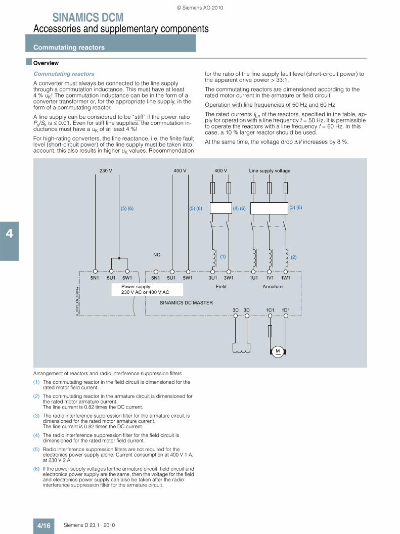
SINAMICS DCMAccessories and supplementary components
Commutating reactors
4/16 Siemens D 23.1 · 2010
4
■ Overview
Commutating reactors
A converter must always be connected to the line supply through a commutation inductance. This must have at least 4 % uK! The commutation inductance can be in the form of a converter transformer or, for the appropriate line supply, in the form of a commutating reactor.
A line supply can be considered to be “stiff” if the power ratio Ps/Sk is ≤ 0.01. Even for stiff line supplies, the commutation in-ductance must have a uK of at least 4 %!
For high-rating converters, the line reactance, i.e. the finite fault level (short-circuit power) of the line supply must be taken into account; this also results in higher uK values. Recommendation
for the ratio of the line supply fault level (short-circuit power) to the apparent drive power > 33:1.
The commutating reactors are dimensioned according to the rated motor current in the armature or field circuit.
Operation with line frequencies of 50 Hz and 60 Hz
The rated currents ILn of the reactors, specified in the table, ap-ply for operation with a line frequency f = 50 Hz. It is permissible to operate the reactors with a line frequency f = 60 Hz. In this case, a 10 % larger reactor should be used.
At the same time, the voltage drop ΔV increases by 8 %.
Arrangement of reactors and radio interference suppression filters
(1) The commutating reactor in the field circuit is dimensioned for the rated motor field current.
(2) The commutating reactor in the armature circuit is dimensioned for the rated motor armature current. The line current is 0.82 times the DC current.
(3) The radio interference suppression filter for the armature circuit is dimensioned for the rated motor armature current.The line current is 0.82 times the DC current.
(4) The radio interference suppression filter for the field circuit is dimensioned for the rated motor field current.
(5) Radio interference suppression filters are not required for the electronics power supply alone. Current consumption at 400 V 1 A, at 230 V 2 A.
(6) If the power supply voltages for the armature circuit, field circuit and electronics power supply are the same, then the voltage for the field and electronics power supply can also be taken after the radio interference suppression filter for the armature circuit.
230 V
NC
5U1 5N1 5U1 5W1 3U1
Field
SINAMICS DC MASTER
Armature
3W1 1U1 1V1 1W1
3C 3D
M
1C1 1D1
5W1
400 V400 V Line supply voltage
Power supply230 V AC or 400 V AC
(1)
(5) (6) (5) (6) (4) (6) (3) (6)
(2)
G_D
023_
EN
_000
04a
5N1
© Siemens AG 2010

SINAMICS DCMAccessories and supplementary components
Commutating reactors
4/17Siemens D 23.1 · 2010
4
■ Selection and ordering data 1)
Note: The commutating reactors are dimensioned according to the rated motor current in the armature and field circuits. For single-phase operation, single-phase commutating reactors should be used in the armature circuit. The following table provides an overview and can be a guide for selection. Please find detailed information in Catalog LV 60.
Note: Commutating reactors for 830 and 950 V on request.
Thermal continuous current 2)
Maximum AC current
Continuous permissible DC current 3)
Commutating reactor
4 % per unit voltage drop uD of the reactor at Ith max and VN
Ith max IL max Idn 400 V 500 V 690 V 750 V
A A A Order No. Order No. Order No. Order No.
Single-phase commutating reactor Ith max = IL max with inductive load
8 8 9.8 4EM4807-1CB00 – – –
10 10 12.3 4EM4911-7CB00 – – –
11.2 11.2 13.7 4EM4911-8CB00 – – –
12.5 12.5 15.3 4EM4912-0CB00 – – –
14 14 17.2 4EM4912-1CB00 – – –
15 15 18.4 4EM5000-2CB00 – – –
18 18 22 4EM5005-6CB00 – – –
20 20 24.5 4EM5005-7CB00 – – –
22.4 22.4 27.4 4EM5005-8CB00 – – –
24 24 29.4 4EM5100-2CB00 – – –
28 28 34 4EM6100-2CB00 – – –
31.5 31.5 39 4EM6100-3CB00 – – –
35.5 35.5 43 4EM5212-8CB00 – – –
40 40 49 4EM5200-1CB00 – – –
45 45 55 4EM6200-3CB00 – – –
50 50 61 4EM5316-6CB00 – – –
Three-phase commutating reactor Ith max = 0.8 × IL max with inductive load, 50 Hz 3 AC
16 20 19.6 4EP3601-3DS00 4EP3601-8DS00 – –
18 22.4 22 4EP3601-4DS00 4EP3602-0DS00 – –
20 25 24.5 4EP3601-5DS00 4EP3702-0DS00 – –
22.4 28 27.4 – 4EP3702-1DS00 – –
25 31.5 31 4EP3701-5DS00 4EP3702-2DS00 – –
28 35.5 34 4EP3701-6DS00 4EP3801-7DS00 – –
31.5 40 39 4EP3701-7DS00 4EP3801-8DS00 – –
35.5 45 43 4EP3701-8DS00 4EP3802-0DS00 – –
40 50 49 4EP3800-2DS00 4EP3800-4DS00 – –
45 56 55 4EP3801-6DS00 4EP3901-5DS00 – –
50 63 61 4EP3800-3DS00 4EP3900-3DS00 – –
56 71 69 4EP3901-4DS00 4EP4003-1DS00 – –
63 80 77 4EP3900-2DS00 4EP4000-4DS00 – –
71 91 87 4EP4002-7DS00 4EP4003-2DS00 – –
80 100 98 4EP4000-3DS00 4EU2422-8AA00-0AA0 – –
91 112 112 4EP4002-8DS00 4EU2422-0BA00-0AA0 – –
1) All reactors with VN ≤ 600 V acc. to UL2) Rated current ILn = 0.9 × Ith max3) For a downstream six-pulse bridge circuit
© Siemens AG 2010

SINAMICS DCMAccessories and supplementary components
Commutating reactors
4/18 Siemens D 23.1 · 2010
4
■ Selection and ordering data (continued) 1)
Note: Commutating reactors for 830 and 950 V on request.
Thermal continuous current 2)
Maximum AC current
Continuous permissible DC current 3)
Commutating reactor
4 % per unit voltage drop uD of the reactor at Ith max and VN
Ith max IL max Idn 400 V 500 V 690 V 750 V
A A A Order No. Order No. Order No. Order No.
Three-phase commutating reactor Ith max = 0.8 × IL max with inductive load, 50 Hz 3 AC (continued)
100 125 123 4EP4003-0DS00 4EU2522-6BA00-0AA0 – –
112 140 137 4EU2422-6AA00-0AA0 4EU2522-7BA00-0AA0 – –
125 160 153 4EU2422-7AA00-0AA0 4EU2522-8BA00-0AA0 – –
140 180 172 4EU2522-2BA00-0AA0 4EU2522-0CA00-0AA0 – –
160 200 196 4EU2522-3BA00-0AA0 4EU2722-0CA00-0AA0 – –
180 224 221 4EU2522-4BA00-0AA0 4EU2722-1CA00-0AA0 – –
200 250 245 4EU2522-5BA00-0AA0 4EU2722-2CA00-0AA0 4EU2722-0DA00-1BA0 –
224 280 275 4EU2722-5BA00-0AA0 4EU2722-3CA00-0AA0 4EU3022-8BA00-0AA0 –
250 315 306 4EU2722-6BA00-0AA0 4EU2722-4CA00-0AA0 4EU3022-0CA00-0AA0 4EU3022-2CA00-0AA0
280 355 343 4EU2722-7BA00-0AA0 4EU3022-5BA00-0AA0 4EU3022-1CA00-0AA0 4EU3622-5DA00-0AA0
315 400 386 4EU2722-8BA00-0AA0 4EU3022-6BA00-0AA0 4EU3622-0DA00-0AA0 4EU3622-6DA00-0AA0
355 450 435 4EU3022-1BA00-0AA0 4EU3022-7BA00-0AA0 4EU3622-1DA00-0AA0 4EU3622-7DA00-0AA0
400 500 490 4EU3022-2BA00-0AA0 4EU3622-4CA00-0AA0 4EU3622-2DA00-0AA0 4EU3622-8DA00-1BA0
450 560 551 4EU3022-3BA00-0AA0 4EU3622-5CA00-0AA0 4EU3622-3DA00-0AA0 4EU3622-0EA00-1BA0
500 630 613 4EU3022-4BA00-0AA0 4EU3622-6CA00-0AA0 4EU3622-4DA00-0AA0 4EU3921-1CA00-0A
560 710 686 4EU3622-0CA00-0AA0 4EU3622-7CA00-0AA0 4EU3921-8BA00-0A 4EU3921-2CA00-0A
630 800 772 4EU3622-1CA00-0AA0 4EU3622-8CA00-1BA0 4EU3921-0CA00-0A 4EU4321-4DA00-0A
710 910 870 4EU3622-2CA00-1BA0 4EU3921-6BA00-0A 4EU4321-0DA00-0A 4EU4321-5DA00-0A
800 1 000 980 4EU3622-3CA00-1BA0 4EU3921-7BA00-0A 4EU4321-1DA00-0A 4EU4321-6DA00-0A
910 1 120 1 115 4EU3921-2BA00-0A 4EU4321-4CA00-0A 4EU4321-2DA00-0A 4EU4521-4BA00
980 1 230 1 200 – – 4EU4321-0AY00-0A –
1 000 1 250 1 225 4EU3921-3BA00-0A 4EU4321-5CA00-0A 4EU4321-3DA00-0A 4EU4521-5BA00
1 040 1 300 1 280 4EU3921-0AL00-0A 4EU4321-0AX00-0A 4) – –
1 310 1 640 1 600 4EU4321-0AW00-0A 4EU4521-0AK00 4) 4EU4521-0AP00 –
1 600 2 000 1 951 4EU4321-0CH10-0A 4EU4521-0CP10-0C 4EU5121-0BD10-0C 4EU5021-0AM10-0C
1 800 2 250 2 195 4EU4321-0CK10-0C 4EU4521-0CQ10-0C 4EU5121-0BE10-0C 4EU5221-0BF10-0C
2 000 2 500 2 439 4EU9921-0BG10-0B 4EU5121-0BA10-0C 4EU5121-0BF10-0C 4EU5221-0BG10-0C
2 250 2 812.5 2 744 4EU5021-0AL10-0C 4EU5121-0BB10-0C 4EU5121-0BG10-0C 4EU5221-0BH10-0C
2 500 3 125 3 049 4EU5021-0AK10-0B 4EU5121-0BC10-0C 4EU5421-0AV10-0C 4EU5621-0AW10-0C
1) All reactors with VN ≤ 600 V acc. to UL2) Rated current ILn = 0.9 × Ith max3) For a downstream six-pulse bridge circuit4) Per unit voltage drop of the reactor uD ≅ 4 % at ILn and VN = 575 V
© Siemens AG 2010

SINAMICS DCMAccessories and supplementary components
Circuit-breakers and contactors
4/19Siemens D 23.1 · 2010
4
■ Overview
The main contactor or the circuit-breaker in front of the three-phase armature supply of the converter is used to switch-on the power section in a correct manner when the electronics and the voltage for the thyristor modules is enabled if the unit is still not operational. This is the reason that the contactor or the circuit-breaker must always be energized via terminals XR1-109-110. When a circuit-breaker is used, a motor-operated mechanism must be used to close the circuit-breaker and an undervoltage release to open the circuit-breaker.
Selection criteria
The internal control sequence guarantees that the switching operations are always made in a no-current condition. When selecting the main contactor, the utilization category AC-1 or for a circuit-breaker, the maximum rated current In max should be used as basis. If the current and voltage quantities permit it, then generally, the more cost-effective solution using a contactor is preferred over a circuit-breaker.
■ Overview
SINAMICS DC MASTER applications are in compliance with the EMC product standard EN 61800-3 for electric drives when taking into account that the units are integrated into the plant or system in compliance with EMC rules.
However, EMC legislation does stipulate that the plant or system as a whole must be electromagnetically compatible with its en-vironment.
If radio interference suppression level “A1” according to EN 55011 is to be achieved, then in addition to the commutating reactors, a radio interference suppression filter is also required. Radio interference suppression filters reduce radio interference voltages of the converter that occur in conjunction with the com-mutating reactor. It is only possible to use radio interference sup-pression filters for grounded line supplies.
Radio interference suppression filters generate leakage cur-rents. In accordance with DIN VDE 0160, a PE connection with a cross-section of 10 mm2 is required. For the filters to have opti-mum effect, it is absolutely essential that they and the unit are installed on a single metal plate.
For converter units with 3-phase connection, the minimum rated filter current is equal to the DC output current of the unit times 0.82. For a two-phase connection (field power section or single-phase operation of the armature power section) only two phases are connected to the three-phase radio interference suppres-sion filter. In this case, the line current is equal to the DC field cur-rent.
List of the recommended radio interference suppression filters from EPCOS
Radio interference suppression filters
Rated currentRadio interference suppression filter
Radio interference suppression filter
Terminal cross-section (mm2) or threaded hole
Weight, approx. Dimensions(W × H × D)
A Type kg mm × mm × mm
8 B84143-G8 -R 1 1 7 4 mm2 1.3 80 × 230 × 50
20 B84143-G20 -R 1 1 7 4 mm2 1.3 80 × 230 × 50
36 B84143-G36 -R 1 1 7 6 mm2 2.8 150 × 280 × 60
50 B84143-G50 -R 1 1 7 16 mm2 3.3 150 × 60 × 330
66 B84143-G66 -R 1 1 7 25 mm2 4.4 150 × 330 × 80
90 B84143-G90 -R 1 1 7 25 mm2 4.9 150 × 330 × 80
120 B84143-G120 -R 1 1 7 50 mm2 7.5 200 × 380 × 90
150 B84143-G150 -R 1 1 7 50 mm2 8.0 200 × 380 × 90
220 B84143-G220 -R 1 1 7 95 mm2 11.5 220 × 430 × 110
150 B84143-B150 -S 7 7 M10 13 140 × 310 × 170
180 B84143-B180 -S 7 7 M10 13 140 × 310 × 170
250 B84143-B250 -S 7 7 M10 15 115 × 360 × 190
320 B84143-B320 -S 7 7 M10 21 115 × 360 × 260
400 B84143-B400 -S 7 7 M10 21 115 × 360 × 260
600 B84143-B600 -S 7 7 M10 22 115 × 410 × 260
1 000 B84143-B1000-S 7 7 M12 28 165 × 420 × 300
1 600 B84143-B1600-S 7 7 2 × M12 34 165 × 420 × 300
2 500 B84143-B2500-S 7 7 4 × M12 105 200 × 810 × 385
500 V 2 0
760 V 2 1
690 V 2 4
480 V 0
530 V 2
© Siemens AG 2010
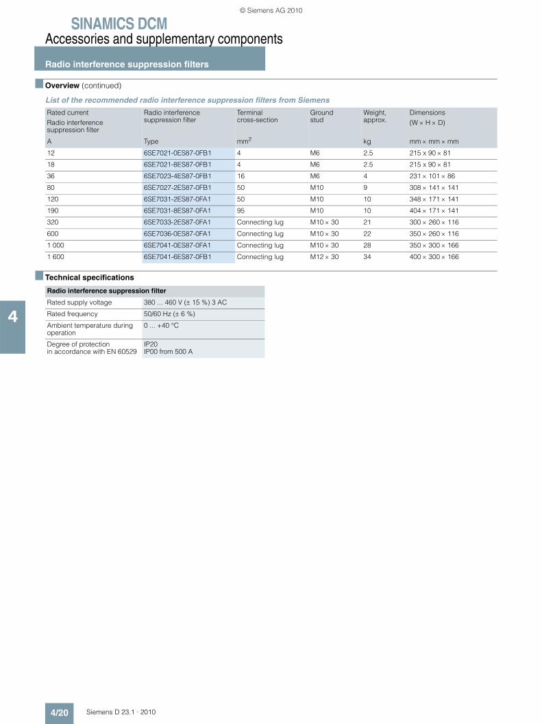
SINAMICS DCMAccessories and supplementary components
Radio interference suppression filters
4/20 Siemens D 23.1 · 2010
4
■ Overview (continued)
List of the recommended radio interference suppression filters from Siemens
■ Technical specifications
Rated current Radio interference suppression filter
Radio interference suppression filter
Terminal cross-section
Ground stud
Weight, approx.
Dimensions(W × H × D)
A Type mm2 kg mm × mm × mm
12 6SE7021-0ES87-0FB1 4 M6 2.5 215 x 90 × 81
18 6SE7021-8ES87-0FB1 4 M6 2.5 215 x 90 × 81
36 6SE7023-4ES87-0FB1 16 M6 4 231 × 101 × 86
80 6SE7027-2ES87-0FB1 50 M10 9 308 × 141 × 141
120 6SE7031-2ES87-0FA1 50 M10 10 348 × 171 × 141
190 6SE7031-8ES87-0FA1 95 M10 10 404 × 171 × 141
320 6SE7033-2ES87-0FA1 Connecting lug M10 × 30 21 300 × 260 × 116
600 6SE7036-0ES87-0FA1 Connecting lug M10 × 30 22 350 × 260 × 116
1 000 6SE7041-0ES87-0FA1 Connecting lug M10 × 30 28 350 × 300 × 166
1 600 6SE7041-6ES87-0FB1 Connecting lug M12 × 30 34 400 × 300 × 166
Radio interference suppression filter
Rated supply voltage 380 ... 460 V (± 15 %) 3 AC
Rated frequency 50/60 Hz (± 6 %)
Ambient temperature during operation
0 ... +40 °C
Degree of protection in accordance with EN 60529
IP20IP00 from 500 A
© Siemens AG 2010
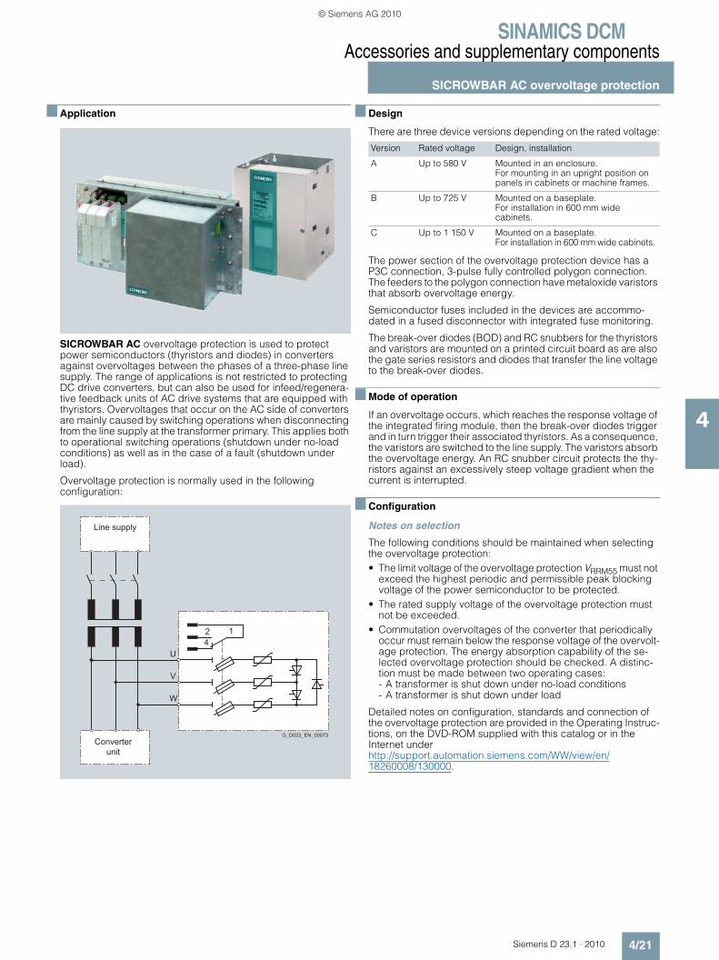
SINAMICS DCMAccessories and supplementary components
SICROWBAR AC overvoltage protection
4/21Siemens D 23.1 · 2010
4
■ Application
SICROWBAR AC overvoltage protection is used to protect power semiconductors (thyristors and diodes) in converters against overvoltages between the phases of a three-phase line supply. The range of applications is not restricted to protecting DC drive converters, but can also be used for infeed/regenera-tive feedback units of AC drive systems that are equipped with thyristors. Overvoltages that occur on the AC side of converters are mainly caused by switching operations when disconnecting from the line supply at the transformer primary. This applies both to operational switching operations (shutdown under no-load conditions) as well as in the case of a fault (shutdown under load).
Overvoltage protection is normally used in the following configuration:
■ Design
There are three device versions depending on the rated voltage:
The power section of the overvoltage protection device has a P3C connection, 3-pulse fully controlled polygon connection. The feeders to the polygon connection have metaloxide varistors that absorb overvoltage energy.
Semiconductor fuses included in the devices are accommo-dated in a fused disconnector with integrated fuse monitoring.
The break-over diodes (BOD) and RC snubbers for the thyristors and varistors are mounted on a printed circuit board as are also the gate series resistors and diodes that transfer the line voltage to the break-over diodes.
■ Mode of operation
If an overvoltage occurs, which reaches the response voltage of the integrated firing module, then the break-over diodes trigger and in turn trigger their associated thyristors. As a consequence, the varistors are switched to the line supply. The varistors absorb the overvoltage energy. An RC snubber circuit protects the thy-ristors against an excessively steep voltage gradient when the current is interrupted.
■ Configuration
Notes on selection
The following conditions should be maintained when selecting the overvoltage protection:• The limit voltage of the overvoltage protection VRRM55 must not
exceed the highest periodic and permissible peak blocking voltage of the power semiconductor to be protected.
• The rated supply voltage of the overvoltage protection must not be exceeded.
• Commutation overvoltages of the converter that periodically occur must remain below the response voltage of the overvolt-age protection. The energy absorption capability of the se-lected overvoltage protection should be checked. A distinc-tion must be made between two operating cases:- A transformer is shut down under no-load conditions- A transformer is shut down under load
Detailed notes on configuration, standards and connection of the overvoltage protection are provided in the Operating Instruc-tions, on the DVD-ROM supplied with this catalog or in the Internet under http://support.automation.siemens.com/WW/view/en/18260008/130000.
G_D023_EN_00073Converter
unit
Line supply
142
W
V
U
Version Rated voltage Design, installation
A Up to 580 V Mounted in an enclosure. For mounting in an upright position on panels in cabinets or machine frames.
B Up to 725 V Mounted on a baseplate. For installation in 600 mm wide cabinets.
C Up to 1 150 V Mounted on a baseplate. For installation in 600 mm wide cabinets.
© Siemens AG 2010

SINAMICS DCMAccessories and supplementary components
SICROWBAR AC overvoltage protection
4/22 Siemens D 23.1 · 2010
4
■ Technical specifications
General technical data SICROWBAR AC overvoltage protection
Degree of protection IP00 acc. to EN 60529
Protection class I according to EN 50178
Overvoltage category III, corresponding to EN 60664
Dimensioning creepages and clearances Pollution degree 2 acc. to EN 50178
Rated insulation voltage (for installation altitudes up to 2 000 m above sea level) 1)
725 V AC for rated supply voltages of 400 ... 725 V 1 200 V AC for rated supply voltages of 850 ... 1 150 V
Installation altitude ≤ 2 000 m above sea level
Permissible ambient temperature
• In operation +5 ... +55 °C
• In storage –40 ... +70 °C
Climate class 3K3 acc. to EN 60721-3-3
Fuse monitoring (microswitch at the fused disconnector, 1 changeover contact)
Flat connector 6.3 mm × 0.8 mm
• Disconnector closed, all fuse links OK 1/2 closed, 1/4 opened
• Disconnector closed, one or several fuse links defective 1/4 closed, 1/2 opened
• Disconnector open 1/4 closed, 1/2 opened
• Maximum switching capacity 50 Hz 250 V AC, 3 A 30 V DC, 3 A
SICROWBAR AC overvoltage protection
7VV3002-3CD20 7VV3002-3AD20 7VV3002-3BD20 7VV3002-3GD20
Max. permissible rated supply voltage VN V 460 550
Nominal response voltage of the BOD element VAN V 1 000 1 200 1 400 1 600
Min. limit voltage of BOD element at 5 °C VRRM_05 V 864 1 056 1 248 1 440
Max. limit voltage of BOD element at 55 °C VRRM_55 V 1 166 1 378 1 590 1 802
Max. permissible peak current, Imax A 200 1 000 2 000
Rated insulation voltage (the insulation voltage is determined by the highest rated supply voltage of the relevant construction type) VISO
V 550
Varistor voltage (breakdown voltage) at TA = 25 °C, 1 mA (data sheet value × 2 for 2 series-connected varistors) VV
V 720 860
Max. energy (for 2 ms) atTA = 85 °C (data sheet value × 2 for 2 series-connected varistors) W0
Ws 600 720
Energy that can be absorbed 100 times (determined from the derating data) W2
Ws 350 419
Energy that can be absorbed 10 000 times (determined from the derating data) W4
Ws 42 50
Version A
Dimensions
• Width mm 265
• Height mm 385
• Depth mm 237
Weight, approx. kg 7
1) Installation altitudes above 2 000 m on request.
© Siemens AG 2010
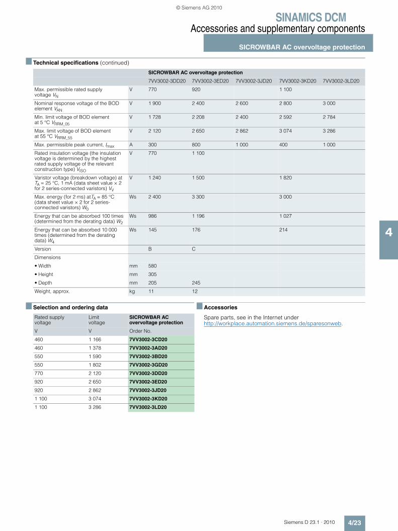
SINAMICS DCMAccessories and supplementary components
SICROWBAR AC overvoltage protection
4/23Siemens D 23.1 · 2010
4
■ Technical specifications (continued)
■ Selection and ordering data ■ Accessories
Spare parts, see in the Internet under http://workplace.automation.siemens.de/sparesonweb.
SICROWBAR AC overvoltage protection
7VV3002-3DD20 7VV3002-3ED20 7VV3002-3JD20 7VV3002-3KD20 7VV3002-3LD20
Max. permissible rated supply voltage VN
V 770 920 1 100
Nominal response voltage of the BOD element VAN
V 1 900 2 400 2 600 2 800 3 000
Min. limit voltage of BOD element at 5 °C VRRM_05
V 1 728 2 208 2 400 2 592 2 784
Max. limit voltage of BOD element at 55 °C VRRM_55
V 2 120 2 650 2 862 3 074 3 286
Max. permissible peak current, Imax A 300 800 1 000 400 1 000
Rated insulation voltage (the insulation voltage is determined by the highest rated supply voltage of the relevant construction type) VISO
V 770 1 100
Varistor voltage (breakdown voltage) at TA = 25 °C, 1 mA (data sheet value × 2 for 2 series-connected varistors) VV
V 1 240 1 500 1 820
Max. energy (for 2 ms) atTA = 85 °C (data sheet value × 2 for 2 series-connected varistors) W0
Ws 2 400 3 300 3 000
Energy that can be absorbed 100 times (determined from the derating data) W2
Ws 986 1 196 1 027
Energy that can be absorbed 10 000 times (determined from the derating data) W4
Ws 145 176 214
Version B C
Dimensions
• Width mm 580
• Height mm 305
• Depth mm 205 245
Weight, approx. kg 11 12
Rated supply voltage
Limit voltage
SICROWBAR AC overvoltage protection
V V Order No.
460 1 166 7VV3002-3CD20
460 1 378 7VV3002-3AD20
550 1 590 7VV3002-3BD20
550 1 802 7VV3002-3GD20
770 2 120 7VV3002-3DD20
920 2 650 7VV3002-3ED20
920 2 862 7VV3002-3JD20
1 100 3 074 7VV3002-3KD20
1 100 3 286 7VV3002-3LD20
© Siemens AG 2010

SINAMICS DCMAccessories and supplementary components
SICROWBAR DC overvoltage protection
4/24 Siemens D 23.1 · 2010
4
■ Application
SICROWBAR DC overvoltage protection protects windings and converters against overvoltage when supplying large induc-tances, e.g. field windings of synchronous machines, DC machines or hoisting solenoids.
Further, it is optionally possible to initiate fast de-excitation – triggered by a higher-level signal. An appropriate de-excitation/discharge resistor must be provided.
■ Design
The most important components of the device are:• Two disk-type thyristors in an anti-parallel connection• A firing circuit, which, depending on the version, triggers a
thyristor in the blocking direction at a defined voltage• A module to detect the voltage at the de-excitation/discharge
resistor, detect the current being conducted, identify when the overvoltage protection device triggers and signal the status using binary outputs.
• The power connections C, D (copper bars) • Terminal XEW1 to connect the sensor cable from the de-exci-
tation/discharge resistor.• An “Optional fast de-excitation” module (Option G11). The
module allows the thyristors to be fired at any time by control-ling three fast relays that are independent of one another.
■ Mode of operation
The two thyristors connected in an anti-parallel connection, located between connections C and D, can briefly (approx. 5 s) conduct the pulse current. The overvoltage triggers a break-over diode (BOD) on the trigger circuit which in turn triggers the blocking thyristor and conducts the firing current past the block-ing thyristor through a diode connected in an anti-parallel con-figuration to its gate/cathode. Independent of the polarity of the overvoltage, the break-over diode is always operated in the same direction using a bridge rectifier and the firing current is limited to between 6 and 8 A using series resistors. The thyristor fires within just a microseconds and the voltage decreases quickly down to the forward voltage (1 to 1.5 V). The load current increases the temperature of the disk-type thyristor within just a few seconds and the thyristor and the stack construction absorb the thermal energy. As a consequence, the load cycle can only be repeated after a cooling time has elapsed (see Technical specifications).
The fast de-excitation option (G11) is connected to the firing circuit in such a way that the thyristors can be triggered at any time by controlling at least one of the three fast relays – that are independent of one another. This assumes that there is sufficient voltage. Generally, this is approximately 5 % of the trigger volt-age. Each of the three relays can be controlled with 24 V DC, 110 V to 125 V DC or 220 V to 240 V DC.
The voltage detection for the de-excitation/discharge resistor is connected to the external de-excitation/discharge resistor. When the voltage detection responds, the supplying converter must be blocked or the current controlled down to zero. The voltage detection module requires an external 24 V DC power supply with min. 100 mA.
The de-excitation/discharge resistor is an external device and is not included in the scope of delivery of the SICROWBAR DC overvoltage protection. Its resistance must be so low that even at the highest load current, the voltage is still under the destruc-tion limit of the supplying converter and/or the winding to be pro-tected. The lowest possible resistance is defined by the supply voltage and the maximum load current of the converter (dimen-sioning the fuses). The required de-excitation time must also be taken into account when dimensioning the value of the resis-tance.
G_D
023_
EN
_000
74
DCconverter
De-excitation/discharge resistor
Synchronous machine
DCovervoltage protection
XEW1
D C
© Siemens AG 2010

SINAMICS DCMAccessories and supplementary components
SICROWBAR DC overvoltage protection
4/25Siemens D 23.1 · 2010
4
■ Configuration
The complete arrangement comprises a SICROWBAR DC overvoltage protection and de-excitation/discharge resistor.
The following device parameters that are used to select the device must be determined:
1. The firing voltage – if this is reached, then the thyristors of the SICROWBAR DC are turned-on.
2. The maximum current that flows or the maximum I2t value that occurs.
Detailed notes on the configuration, the standards that apply and the connection of the overvoltage protection are provided in the Operating Instructions, on the DVD-ROM supplied with this catalog or in the Internet under http://support.automation.siemens.com/WW/view/en/21690222/130000
Typical load current characteristic for the three device power stages
Cooling-down time
= 4.34 shere: 10 % Imax
10 s
t [s]
G_D
023_
EN
_000
76
τ
-5KG32-5LG32-5MG32
7VV3003-5JG32
-5FG32-5GG32-5HG32
7VV3003-5EG32
-5BG32-5CG32-5DG32
7VV3003-5AG32
I [A]
302520151050
12000
10000
8000
6000
4000
2000
0
Single trigger is periodically possible after 30 min cooling-down time.
30 min 30 min 30 min
G_D
023_
EN
_000
75
t
***
After being triggered twice in a time period < 30 min, a cooling-down time of 300 min is required.
300 min 300 min
G_D
023_
EN
_000
77
t
* * * *
© Siemens AG 2010
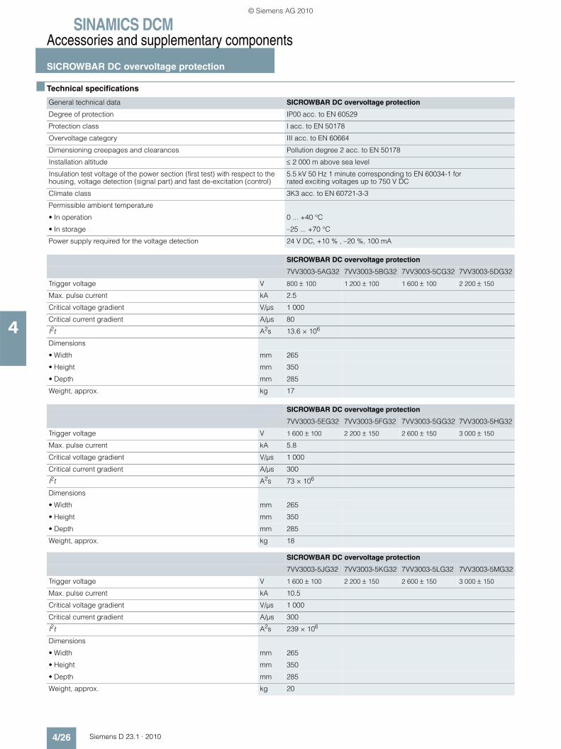
SINAMICS DCMAccessories and supplementary components
SICROWBAR DC overvoltage protection
4/26 Siemens D 23.1 · 2010
4
■ Technical specifications
General technical data SICROWBAR DC overvoltage protection
Degree of protection IP00 acc. to EN 60529
Protection class l acc. to EN 50178
Overvoltage category III acc. to EN 60664
Dimensioning creepages and clearances Pollution degree 2 acc. to EN 50178
Installation altitude ≤ 2 000 m above sea level
Insulation test voltage of the power section (first test) with respect to the housing, voltage detection (signal part) and fast de-excitation (control)
5.5 kV 50 Hz 1 minute corresponding to EN 60034-1 for rated exciting voltages up to 750 V DC
Climate class 3K3 acc. to EN 60721-3-3
Permissible ambient temperature
• In operation 0 ... +40 °C
• In storage –25 ... +70 °C
Power supply required for the voltage detection 24 V DC, +10 % , –20 %, 100 mA
SICROWBAR DC overvoltage protection
7VV3003-5AG32 7VV3003-5BG32 7VV3003-5CG32 7VV3003-5DG32
Trigger voltage V 800 ± 100 1 200 ± 100 1 600 ± 100 2 200 ± 150
Max. pulse current kA 2.5
Critical voltage gradient V/µs 1 000
Critical current gradient A/µs 80
I2t A2s 13.6 × 10⁶
Dimensions
• Width mm 265
• Height mm 350
• Depth mm 285
Weight, approx. kg 17
SICROWBAR DC overvoltage protection
7VV3003-5EG32 7VV3003-5FG32 7VV3003-5GG32 7VV3003-5HG32
Trigger voltage V 1 600 ± 100 2 200 ± 150 2 600 ± 150 3 000 ± 150
Max. pulse current kA 5.8
Critical voltage gradient V/µs 1 000
Critical current gradient A/µs 300
I2t A2s 73 × 106
Dimensions
• Width mm 265
• Height mm 350
• Depth mm 285
Weight, approx. kg 18
SICROWBAR DC overvoltage protection
7VV3003-5JG32 7VV3003-5KG32 7VV3003-5LG32 7VV3003-5MG32
Trigger voltage V 1 600 ± 100 2 200 ± 150 2 600 ± 150 3 000 ± 150
Max. pulse current kA 10.5
Critical voltage gradient V/µs 1 000
Critical current gradient A/µs 300
I2t A2s 239 × 106
Dimensions
• Width mm 265
• Height mm 350
• Depth mm 285
Weight, approx. kg 20
© Siemens AG 2010
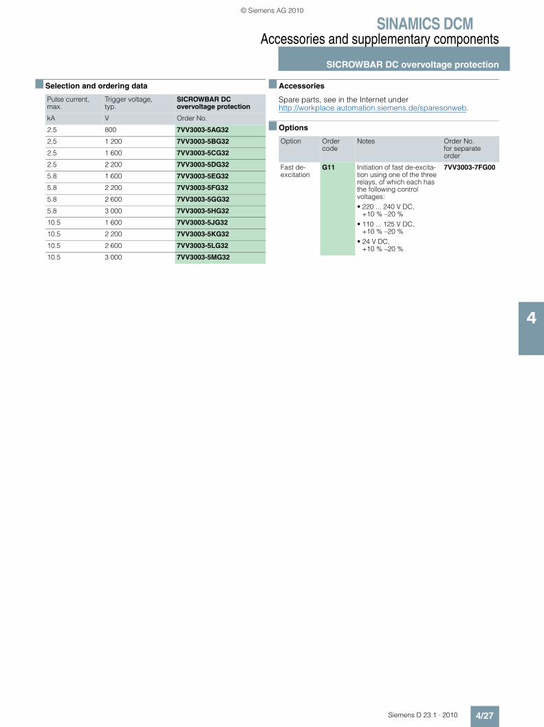
SINAMICS DCMAccessories and supplementary components
SICROWBAR DC overvoltage protection
4/27Siemens D 23.1 · 2010
4
■ Selection and ordering data ■ Accessories
Spare parts, see in the Internet under http://workplace.automation.siemens.de/sparesonweb.
■ Options
Pulse current, max.
Trigger voltage, typ.
SICROWBAR DCovervoltage protection
kA V Order No.
2.5 800 7VV3003-5AG32
2.5 1 200 7VV3003-5BG32
2.5 1 600 7VV3003-5CG32
2.5 2 200 7VV3003-5DG32
5.8 1 600 7VV3003-5EG32
5.8 2 200 7VV3003-5FG32
5.8 2 600 7VV3003-5GG32
5.8 3 000 7VV3003-5HG32
10.5 1 600 7VV3003-5JG32
10.5 2 200 7VV3003-5KG32
10.5 2 600 7VV3003-5LG32
10.5 3 000 7VV3003-5MG32
Option Order code
Notes Order No. for separate order
Fast de-excitation
G11 Initiation of fast de-excita-tion using one of the three relays, of which each has the following control voltages: • 220 ... 240 V DC,
+10 % –20 %• 110 ... 125 V DC,
+10 % –20 %• 24 V DC,
+10 % –20 %
7VV3003-7FG00
© Siemens AG 2010

SINAMICS DCMAccessories and supplementary components
SIMOREG CCP
4/28 Siemens D 23.1 · 2010
4
■ Overview
SIMOREG CCP
The Converter Commutation Protector SIMOREG CCP is used to protect line-commutated SINAMICS DC MASTER converters in inverter operation against inverter commutation faults.
For line-commutated inverters, an appropriate line-side counter voltage is required in order to commutate the current between the individual power semiconductors. Commutation can be pre-vented from being completed (commutation fault) as a result of uncontrolled switching operations, line supply dips (weak line supplies, thunderstorms, etc.). As a result, in the regenerative feedback direction, a high current flows through the line supply or a cross-current in the converter. This can result in fuses blow-ing or under certain circumstances can destroy the semicon-ductors.
The software of the SINAMICS DC MASTER identifies if inverter commutation faults are pending and then issues the command to turn off the power semiconductors in the converter to the SIMOREG CCP. SIMOREG CCP then turns off the power semi-conductors, ensures that the conditions to reduce the current in the motor are present and absorbs the magnetic energy stored in the motor as electric energy.
■ Benefits
SIMOREG CCP limits the current that flows when inverter com-mutation faults occur to a non-hazardous value so that the thy-ristors and the associated super-fast fuses are protected. This eliminates the complex and time consuming replacement of fuses after inverter commutation faults.
Although inverter commutation faults cannot be prevented, their effects can be.7 Gear units and the driven machine are protected by shutting
off the current in time before it reaches its possible maximum value in the case of a fault therefore protecting them against inadmissibly high torque surges.
7 For high rated system currents, up until now, high-speed DC circuit-breakers were used to protect the fuses against rup-ture. By using the CCP, protection is now cost-effectively pos-sible even for lower line currents, whereby SIMOREG CCP has the following advantages when compared to high-speed DC circuit-breakers even at high current levels: - Protection also for circulating currents- Lower system costs- Lower space requirements- No additional air reactor to reduce the current rate-of-rise
when a fault occurs- Lower operating costs, as it requires no maintenance- High degree of availability
■ Design
SIMOREG CCP distinguishes itself as a result of the compact and space-saving design.
■ Function
The line supply voltage, line current as well as the armature volt-age are continually sensed in the SINAMICS DC MASTER.
A possible commutation fault (inverter commutation fault – in-verter shoot-through) is detected from these quantities, which results in the following measures being initiated:
1. The firing pulses are immediately disabled in the SINAMICS DC MASTER
2. The converter sends a “turn-off command” to SIMOREG CCP (via the serial interface).
3. SIMOREG CCP turns off the thyristors by connecting the pre-charged quenching capacitors anti-parallel to all thyristors. As a consequence, the current commutates from the converter into SIMOREG CCP. The quenching capacitors are initially dis-charged by the currents that they accept and they are then charged with the reverse polarity. The armature current starts to decrease as soon as the voltage of the quenching capacitors has reached the value of the motor EMF. However, the armature voltage continues to increase. As soon as it has reached the limit value, resistors are switched-in, which absorb the energy fed back from the motor during the remaining time of the current re-duction phase.
4. A fault message is initiated in the SINAMICS DC MASTER.
5. The SIMOREG CCP re-charges the quenching capacitors with the reverse polarity so that a new quenching operation is possi-ble.
Each time that the line supply voltage is switched in (e.g. via a line contactor), SIMOREG CCP requires approximately 3 s until it is ready for use as the quenching capacitors must first be charged up.
After a quenching operation, SIMOREG CCP requires a certain time until it is ready for use again. The duration depends on the operations during the quenching process and immediately after-wards. On one hand, the quenching capacitors in SIMOREG CCP must be charged to the required value with the reverse polarity (approx. 10 s). On the other hand, the chopper resistors, that convert the energy into heat when the armature current is reduced, require a cooling time calculated using a algorithm in the software. Depending on the amount of energy that was dis-sipated, this can take up to approx. 20 min.
SINAMICS DC MASTER has setting and monitoring parameters for commissioning, operation, monitoring and diagnostics of the SIMOREG CCP. The state of the SIMOREG CCP is signaled via connectors and the triggering of the SIMOREG CCP or errone-ous states are signaled using fault and alarm messages.
Data is exchanged between the SINAMICS DC MASTER and SIMOREG CCP via the serial interface.
© Siemens AG 2010

SINAMICS DCMAccessories and supplementary components
SIMOREG CCP
4/29Siemens D 23.1 · 2010
4
■ Integration
SINAMICS DC MASTER – SIMOREG CCP
The following table lists the SIMOREG CCP units that are suit-able for the particular SINAMICS DC MASTER.
This information is based on the rated unit data (taking into con-sideration the particular limit values) of the components and on the other hand, typical rated data for Siemens DC motors from Catalog DA 12 · 2008.
Note: For plant and system configurations with reduced rated values (e.g. DC rating, US rating, voltage derating), under certain cir-cumstances, suitable combinations of units can be found that are not listed in the table.
For detailed engineering and when selecting the appropriate CCP, our technical support personnel can provide you with help through the local Siemens office. Please specify the following plant or system data:• Line supply voltages and power sections• Required undervoltage range of the power section • Rated motor armature voltage• Rated motor current• Details on the required overcurrent where necessary
(magnitude, cycle duration)• Inductance of the load (motor, cable plus if required a
smoothing reactor)
SINAMICS DC MASTER SIMOREG CCP
Type Rated DC voltage
Rated DC current
Type Rated voltage
Rated current
V A V A
6RA8078-6DV62-0AA0 420 280 6RA7085-6FC00-0 460 V 3 AC DC 600
6RA8081-6DV62-0AA0 400
6RA8085-6DV62-0AA0 600
6RA8078-6FV62-0AA0 480 280
6RA8082-6FV62-0AA0 450
6RA8085-6FV62-0AA0 600
6RA8085-6DV62-0AA0 420 600 6RA7091-6FC00-0 DC 1 200
6RA8087-6DV62-0AA0 850
6RA8091-6DV62-0AA0 1 200
6RA8085-6FV62-0AA0 480 600
6RA8087-6FV62-0AA0 850
6RA8091-6FV62-0AA0 1 200
6RA8091-6DV62-0AA0 420 1 200 6RA7095-6FC00-0 DC 2 000
6RA8093-4DV62-0AA0 1 600
6RA8095-4DV62-0AA0 2 000
6RA8081-6GV62-0AA0 600 400 6RA7090-6KC00-0 690 V 3 AC DC 1 000
6RA8085-6GV62-0AA0 600
6RA8087-6GV62-0AA0 850
6RA8086-6KV62-0AA0 725 760
6RA8090-6KV62-0AA0 1 000
6RA8090-6GV62-0AA0 600 1 100 6RA7095-6KC00-0 DC 2 000
6RA8093-4GV62-0AA0 1 600
6RA8095-4GV62-0AA0 2 000
6RA8090-6KV62-0AA0 725 1 000
6RA8093-4KV62-0AA0 1 500
6RA8095-4KV62-0AA0 2 000
© Siemens AG 2010
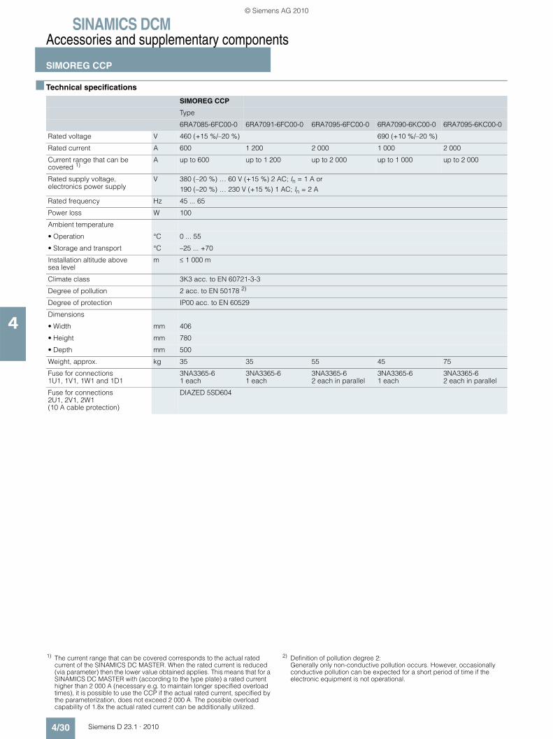
SINAMICS DCMAccessories and supplementary components
SIMOREG CCP
4/30 Siemens D 23.1 · 2010
4
■ Technical specifications
SIMOREG CCP
Type
6RA7085-6FC00-0 6RA7091-6FC00-0 6RA7095-6FC00-0 6RA7090-6KC00-0 6RA7095-6KC00-0
Rated voltage V 460 (+15 %/–20 %) 690 (+10 %/–20 %)
Rated current A 600 1 200 2 000 1 000 2 000
Current range that can be covered 1)
A up to 600 up to 1 200 up to 2 000 up to 1 000 up to 2 000
Rated supply voltage, electronics power supply
V 380 (–20 %) … 60 V (+15 %) 2 AC; In = 1 A or190 (–20 %) … 230 V (+15 %) 1 AC; In = 2 A
Rated frequency Hz 45 ... 65
Power loss W 100
Ambient temperature
• Operation °C 0 ... 55
• Storage and transport °C –25 ... +70
Installation altitude above sea level
m ≤ 1 000 m
Climate class 3K3 acc. to EN 60721-3-3
Degree of pollution 2 acc. to EN 50178 2)
Degree of protection IP00 acc. to EN 60529
Dimensions
• Width mm 406
• Height mm 780
• Depth mm 500
Weight, approx. kg 35 35 55 45 75
Fuse for connections 1U1, 1V1, 1W1 and 1D1
3NA3365-61 each
3NA3365-61 each
3NA3365-62 each in parallel
3NA3365-61 each
3NA3365-62 each in parallel
Fuse for connections 2U1, 2V1, 2W1 (10 A cable protection)
DIAZED 5SD604
1) The current range that can be covered corresponds to the actual rated current of the SINAMICS DC MASTER. When the rated current is reduced (via parameter) then the lower value obtained applies. This means that for a SINAMICS DC MASTER with (according to the type plate) a rated current higher than 2 000 A (necessary e.g. to maintain longer specified overload times), it is possible to use the CCP if the actual rated current, specified by the parameterization, does not exceed 2 000 A. The possible overload capability of 1.8x the actual rated current can be additionally utilized.
2) Definition of pollution degree 2: Generally only non-conductive pollution occurs. However, occasionally conductive pollution can be expected for a short period of time if the electronic equipment is not operational.
© Siemens AG 2010
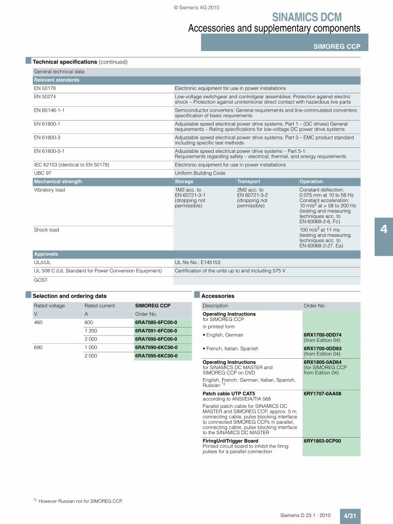
SINAMICS DCMAccessories and supplementary components
SIMOREG CCP
4/31Siemens D 23.1 · 2010
4
■ Technical specifications (continued)
■ Selection and ordering data
■ Accessories
General technical data
Relevant standards
EN 50178 Electronic equipment for use in power installations
EN 50274 Low-voltage switchgear and controlgear assemblies: Protection against electric shock – Protection against unintentional direct contact with hazardous live parts
EN 60146-1-1 Semiconductor converters: General requirements and line-commutated converters; specification of basic requirements
EN 61800-1 Adjustable speed electrical power drive systems, Part 1 – (DC drives) General requirements – Rating specifications for low-voltage DC power drive systems
EN 61800-3 Adjustable speed electrical power drive systems, Part 3 – EMC product standard including specific test methods
EN 61800-5-1 Adjustable speed electrical power drive systems – Part 5-1: Requirements regarding safety – electrical, thermal, and energy requirements
IEC 62103 (identical to EN 50178) Electronic equipment for use in power installations
UBC 97 Uniform Building Code
Mechanical strength Storage Transport Operation
Vibratory load 1M2 acc. to EN 60721-3-1(dropping not permissible)
2M2 acc. to EN 60721-3-2(dropping not permissible)
Constant deflection:0.075 mm at 10 to 58 HzConstant acceleration:10 m/s2 at > 58 to 200 Hz(testing and measuring techniques acc. to EN 60068-2-6, Fc)
Shock load 100 m/s2 at 11 ms (testing and measuring techniques acc. to EN 60068-2-27, Ea)
Approvals
UL/cUL UL file No.: E145153
UL 508 C (UL Standard for Power Conversion Equipment) Certification of the units up to and including 575 V
GOST
Rated voltage Rated current SIMOREG CCP
V A Order No.
460 600 6RA7085-6FC00-0
1 200 6RA7091-6FC00-0
2 000 6RA7095-6FC00-0
690 1 000 6RA7090-6KC00-0
2 000 6RA7095-6KC00-0
1) However Russian not for SIMOREG CCP.
Description Order No.
Operating Instructions for SIMOREG CCPin printed form
• English, German 6RX1700-0DD74 (from Edition 04)
• French, Italian, Spanish 6RX1700-0DD83 (from Edition 04)
Operating Instructions for SINAMICS DC MASTER and SIMOREG CCP on DVDEnglish, French, German, Italian, Spanish, Russian 1)
6RX1800-0AD64 (for SIMOREG CCP from Edition 04)
Patch cable UTP CAT5 according to ANSI/EIA/TIA 568Parallel patch cable for SINAMICS DC MASTER and SIMOREG CCP, approx. 5 m,connecting cable, pulse blocking interface to connected SIMOREG CCPs in parallel,connecting cable, pulse blocking interface to the SINAMICS DC MASTER
6RY1707-0AA08
FiringUnitTrigger Board Printed circuit board to inhibit the firing pulses for a parallel connection
6RY1803-0CP00
© Siemens AG 2010

SINAMICS DCMAccessories and supplementary components
SIMOREG CCP
4/32 Siemens D 23.1 · 2010
4
■ Schematics
Block diagram
Operation without a main contactor is not permissible. The control voltage for the main contactor (or the circuit-breaker) must always be routed via terminal XR (connection 109 and 110) of the SINAMICS DC MASTER unit and via terminal X_Contactor (connections 4 and 5) of the SIMOREG CCP.
For applications with SIMOREG CCP, in the case of a fault, the converter or SIMOREG CCP must be able to disconnect safely the arrangement from the line supply. Further, it must be ensured that the total of the delay times of all of the switching elements in the control circuit must not exceed the time set using the corre-sponding parameters. When SINAMICS DC MASTER units are connected in parallel, each unit is directly connected to a SIMOREG CCP in parallel (refer to the block diagram for the parallel connection).
Fan FieldPowersupply
Armature
Connection, see operating instructions SINAMICS DC MASTER
Power supply
or
G_D023_EN_00002a
3 AC 50 ... 60 Hz, 380 ... 480 V
3 AC 50 ... 60 Hz, 400 ... 690 V
1 AC 50 ... 60 Hz, 230 V
All power connections either at 400 ... 690 V or at 380 ... 480 V
1U1
1V1
1W1
L1 L2 L3 3U1
3W1
5W1
5U1
5N1
SINAMICS DC MASTER
109 110XR1
5U1
5W1
5N1
NC
Power InterfaceC98043-A7046
1U1
1V1
1W1
5U1
5W1
5N1
SIMOREG CCP
2U1
2V1
2W1
1 2 3 4 5X_Contactor
1 2 3XP
1 2 3XP
K11C
1 (1
D1)
1D1
(1C
1)3C 3D
1C1
(1D
1)
1D1
(1C
1)
M
© Siemens AG 2010
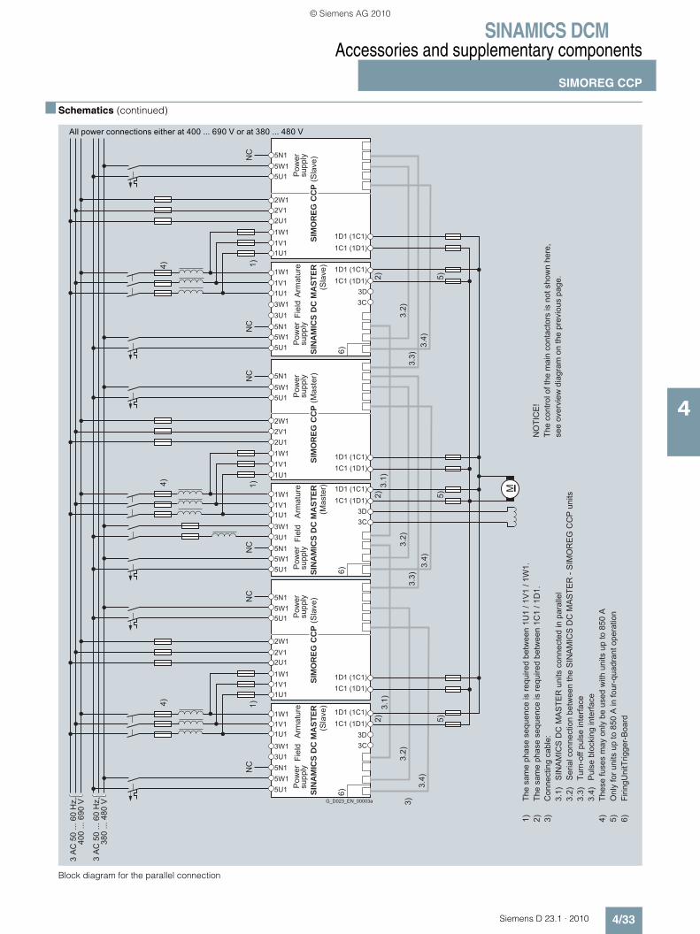
SINAMICS DCMAccessories and supplementary components
SIMOREG CCP
4/33Siemens D 23.1 · 2010
4
■ Schematics (continued)
Block diagram for the parallel connection
see
over
view
dia
gram
on
the
prev
ious
pag
e.Th
e co
ntro
l of t
he m
ain
cont
acto
rs is
not
sho
wn
here
,N
OTI
CE
!
Onl
y fo
r uni
ts u
p to
850
A in
four
-qua
dran
t ope
ratio
n5)
Firin
gUni
tTrig
ger-
Boa
rd6)
Thes
e fu
ses
may
onl
y be
use
d w
ith u
nits
up
to 8
50 A
4)P
ulse
blo
ckin
g in
terfa
ce3.
4)Tu
rn-o
ff pu
lse
inte
rface
3.3)
Ser
ial c
onne
ctio
n be
twee
n th
e S
INA
MIC
S D
C M
AS
TER
- S
IMO
RE
G C
CP
uni
ts3.
2)S
INA
MIC
S D
C M
AS
TER
uni
ts c
onne
cted
in p
aral
lel
3.1)
Con
nect
ing
cabl
e:3)
The
sam
e ph
ase
sequ
ence
is re
quire
d be
twee
n 1C
1 / 1
D1.
2)Th
e sa
me
phas
e se
quen
ce is
requ
ired
betw
een
1U1
/ 1V
1 / 1
W1.
1)
380
... 4
80 V
3 A
C 5
0 ...
60
Hz,
400
... 6
90 V
3 A
C 5
0 ...
60
Hz,
M
G_D023_EN_00003a
Pow
er
supp
lyP
ower
su
pply
(Sla
ve)
Arm
atur
eP
ower
su
pply
Fiel
dP
ower
su
pply
(Mas
ter)
Arm
atur
eP
ower
su
pply
Fiel
d
(Sla
ve)
Arm
atur
eP
ower
su
pply
Fiel
d
(Sla
ve)
(Mas
ter)
(Sla
ve)NC
NC
NC
NC
NC
NC
All power connections either at 400 ... 690 V or at 380 ... 480 V
SIN
AM
ICS
DC
MA
STER
SI
NA
MIC
S D
C M
AST
ER
SIM
OR
EG C
CP
SIM
OR
EG C
CP
SIM
OR
EG C
CP
4) 1)
4) 1)
1C1 (1D1)1D1 (1C1)
5N1
5U15W1
2W12V12U11W11V11U1
1C1 (1D1)
1D1 (1C1)
5N1
5U15W1
2W12V12U11W11V11U1
3C3D
1C1 (1D1)1D1 (1C1)1W1
1V11U13W13U15N15W15U1
3C3D
1C1 (1D1)1D1 (1C1)
1W11V11U13W13U15N15W15U1
1C1 (1D1)1D1 (1C1)
5N1
5U15W1
2W12V12U1
1W11V11U1
3C3D
1C1 (1D1)1D1 (1C1)
3.1)
3.2)
3.2)
3.3)
3.3)
3.4)
3.1)
3.2)
5)2)
5)2)
5)2)
3)
1W11V11U1
3W13U1
4) 1)
5N15W15U1
SIN
AM
ICS
DC
MA
STER
3.4)
3.4)
6)6)
6)
© Siemens AG 2010
SINAMICS DCMAccessories and supplementary components
Notes
4/34 Siemens D 23.1 · 2010
4
© Siemens AG 2010

Siemens D 23.1 · 2010
55/2 Dynamic overload capability5/2 Overview5/2 • Determining the dynamic overload
capability5/15 • Load classes5/17 • Duty cycles for two-quadrant operation5/18 • Duty cycles for four-quadrant operation
5/19 Parallel connection5/19 Overview5/19 • Parallel connection of
SINAMICS DC MASTER units
5/20 12-pulse operation5/20 Overview5/20 • SINAMICS DC MASTER for
12-pulse operation
5/20 Supply of high inductances5/20 Overview5/20 • SINAMICS DC MASTER to supply
high inductances
5/20 Protection against condensation5/20 Overview5/20 • Protection against condensation
5/21 Characteristic values of the pulse tachometer evaluation electronics
5/21 Overview5/21 • Input pulse levels5/21 • Switching frequency5/21 • Cable, cable length, shield connection
5/22 Notes for EMC-compliant drive installation
5/22 Overview5/22 • Notes for EMC-compliant installation5/22 • Basic information about EMC5/24 • EMC-compliant drive installation
(installation instructions)
5/28 Harmonics5/28 Overview5/28 • Line-side harmonics produced by
converter units in a fully-controlled three-phase bridge circuit B6C and (B6)A(B6)C
Engineering information
© Siemens AG 2010
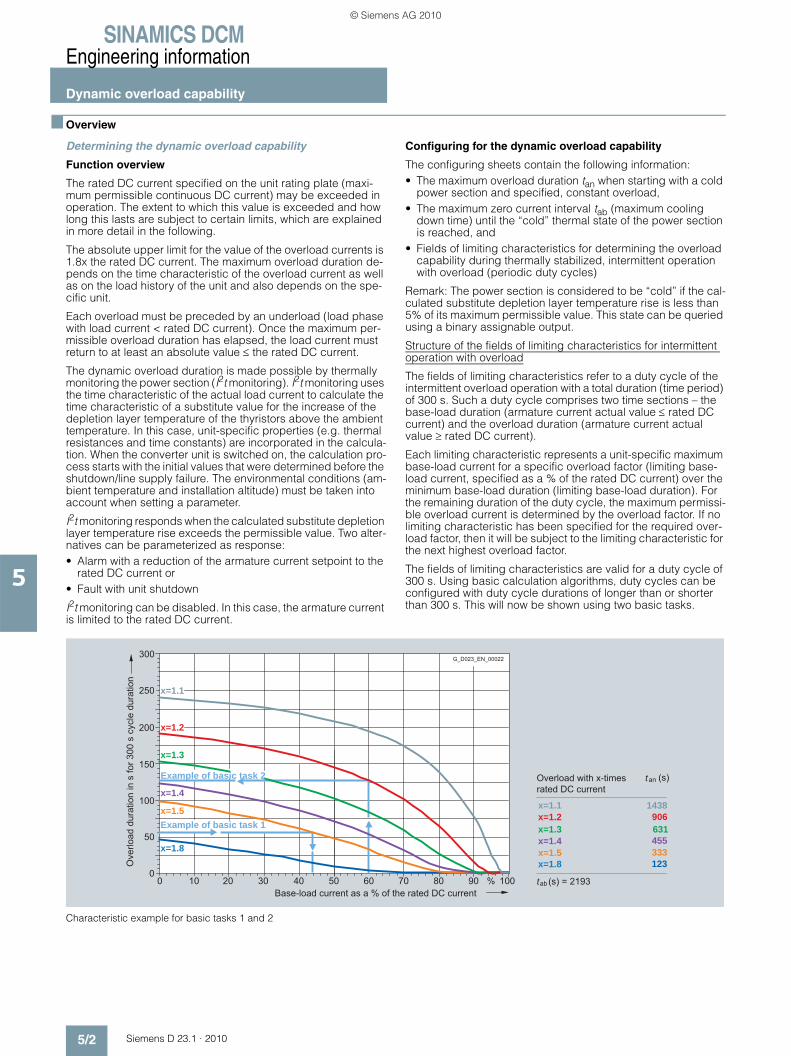
SINAMICS DCMEngineering information
Dynamic overload capability
5/2 Siemens D 23.1 · 2010
5
■ Overview
Determining the dynamic overload capability
Function overview
The rated DC current specified on the unit rating plate (maxi-mum permissible continuous DC current) may be exceeded in operation. The extent to which this value is exceeded and how long this lasts are subject to certain limits, which are explained in more detail in the following.
The absolute upper limit for the value of the overload currents is 1.8x the rated DC current. The maximum overload duration de-pends on the time characteristic of the overload current as well as on the load history of the unit and also depends on the spe-cific unit.
Each overload must be preceded by an underload (load phase with load current < rated DC current). Once the maximum per-missible overload duration has elapsed, the load current must return to at least an absolute value ≤ the rated DC current.
The dynamic overload duration is made possible by thermally monitoring the power section (I2t monitoring). I2t monitoring uses the time characteristic of the actual load current to calculate the time characteristic of a substitute value for the increase of the depletion layer temperature of the thyristors above the ambient temperature. In this case, unit-specific properties (e.g. thermal resistances and time constants) are incorporated in the calcula-tion. When the converter unit is switched on, the calculation pro-cess starts with the initial values that were determined before the shutdown/line supply failure. The environmental conditions (am-bient temperature and installation altitude) must be taken into account when setting a parameter.
I2t monitoring responds when the calculated substitute depletion layer temperature rise exceeds the permissible value. Two alter-natives can be parameterized as response:• Alarm with a reduction of the armature current setpoint to the
rated DC current or• Fault with unit shutdown
I2t monitoring can be disabled. In this case, the armature current is limited to the rated DC current.
Configuring for the dynamic overload capability
The configuring sheets contain the following information:• The maximum overload duration tan when starting with a cold
power section and specified, constant overload,• The maximum zero current interval tab (maximum cooling
down time) until the “cold” thermal state of the power section is reached, and
• Fields of limiting characteristics for determining the overload capability during thermally stabilized, intermittent operation with overload (periodic duty cycles)
Remark: The power section is considered to be “cold” if the cal-culated substitute depletion layer temperature rise is less than 5% of its maximum permissible value. This state can be queried using a binary assignable output.
Structure of the fields of limiting characteristics for intermittent operation with overload
The fields of limiting characteristics refer to a duty cycle of the intermittent overload operation with a total duration (time period) of 300 s. Such a duty cycle comprises two time sections – the base-load duration (armature current actual value ≤ rated DC current) and the overload duration (armature current actual value ≥ rated DC current).
Each limiting characteristic represents a unit-specific maximum base-load current for a specific overload factor (limiting base-load current, specified as a % of the rated DC current) over the minimum base-load duration (limiting base-load duration). For the remaining duration of the duty cycle, the maximum permissi-ble overload current is determined by the overload factor. If no limiting characteristic has been specified for the required over-load factor, then it will be subject to the limiting characteristic for the next highest overload factor.
The fields of limiting characteristics are valid for a duty cycle of 300 s. Using basic calculation algorithms, duty cycles can be configured with duty cycle durations of longer than or shorter than 300 s. This will now be shown using two basic tasks.
Characteristic example for basic tasks 1 and 2
300
200
250
100
150
50
050403020100 100%90807060
1438 906 631455333123
Overload with x-timesrated DC current
(s)an
(s) = 2193ab
Example of basic task 2
Example of basic task 1
Ove
rload
dur
atio
n in
s fo
r 300
s c
ycle
dur
atio
n
Base-load current as a % of the rated DC current
G_D023_EN_00022
t
t
x=1.1x=1.2x=1.3x=1.4x=1.5x=1.8
x=1.1
x=1.2
x=1.3
x=1.4
x=1.5
x=1.8
© Siemens AG 2010

SINAMICS DCMEngineering information
Dynamic overload capability
5/3Siemens D 23.1 · 2010
5
■ Overview (continued)
Basic task 1 • Given:
Unit, cycle duration, overload factor, overload duration• To be found:
(Min.) base-load duration and max. base-load current• Solution:
Example for basic task 1 • Given:
- Unit with 30 A- Cycle duration 113.2 s- Overload factor 1.45- Overload duration 20 s
• To be found: - (Min.) base-load duration- Max. base-load current
• Solution: - Limiting characteristic for a unit with 30 A- Overload factor 1.5- Overload duration300 = 300 s/113.2 s × 20 s = 53 s →- Max. base-load current = 44 % Irated = 13.2 A
Basic task 2 • Given:
Unit, cycle duration, overload factor, base-load current• To be found:
Maximum overload duration, minimum base-load duration• Solution:
Example for basic task 2 • Given:
- Unit with 30 A- Cycle duration 140 s- Overload factor 1.15- Base load current = 0.6 × Irated = 18 A
• To be found: - Maximum overload duration- Minimum base-load duration
Solution: - Limiting characteristic for a unit with 30 A- Overload factor 1.2- Base-load current = 60 % Irated →- Overload duration300 = 127 s- Max. overload duration = 140 s/300 s × 127 s = 59 s- Min. base-load duration = 140 s - 59 s = 81 s
Base-load duration300 = min. base-load duration for 300 s cycle duration (300 s overload duration)
Overload duration300 = max. overload duration for 300 s cycle duration
Cycle duration
< 300 s ≥ 300 s
1. Determine the characteristic Select the limiting characteristic for the specific unit and the specific overload factor
2. Overload duration300 = 300 s/cycle duration × overload duration Overload duration300
3. Base-load duration300 = 300 s – overload duration300
4. Base-load duration300 < base-load duration300 for max. base-load current = 0
Yes: Required duty cycle cannot be configuredNo: Read the max. base-load current for overload duration300 from the limiting characteristic
5. Determine the percentage for the base-load current
Read the percentage for the base-load currents from the diagram
Cycle duration
< 300 s ≥ 300 s
1. Determine the characteristic Select the limiting characteristic for the specific unit and the specific overload factor
2. Max. overload duration = (Cycle duration/300 s) × overload duration300 300 s – base-load duration300
3. Min. base-load duration = Cycle duration – max. overload duration Cycle duration – max. overload duration
© Siemens AG 2010
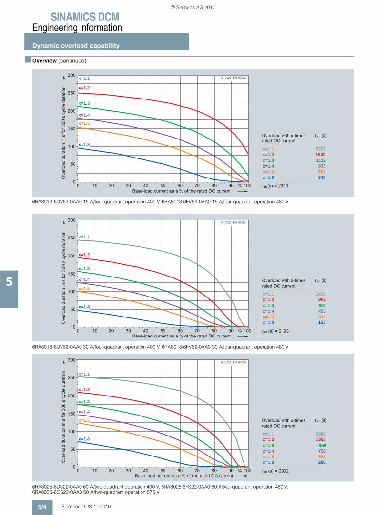
SINAMICS DCMEngineering information
Dynamic overload capability
5/4 Siemens D 23.1 · 2010
5
■ Overview (continued)
6RA8013-6DV62-0AA0 15 A/four-quadrant operation 400 V, 6RA8013-6FV62-0AA0 15 A/four-quadrant operation 480 V
6RA8018-6DV62-0AA0 30 A/four-quadrant operation 400 V, 6RA8018-6FV62-0AA0 30 A/four-quadrant operation 480 V
6RA8025-6DS22-0AA0 60 A/two-quadrant operation 400 V, 6RA8025-6FS22-0AA0 60 A/two-quadrant operation 480 V, 6RA8025-6GS22-0AA0 60 A/two-quadrant operation 575 V
300
200
250
100
150
50
050403020100 100%90807060
9227 1633 1112
833651342
Overload with x-timesrated DC current
(s)an
(s) = 2303ab
Ove
rload
dur
atio
n in
s fo
r 300
s c
ycle
dur
atio
n
Base-load current as a % of the rated DC current
G_D023_EN_00023
t
t
x=1.1x=1.2x=1.3x=1.4x=1.5x=1.8
x=1.2
x=1.1
x=1.3
x=1.4
x=1.5
x=1.8
300
200
250
100
150
50
050403020100 100%90807060
1438 906 631455333123
x=1.1x=1.2x=1.3x=1.4x=1.5x=1.8
x=1.1
x=1.2
x=1.3
x=1.4
x=1.5
x=1.8
Overload with x-timesrated DC current
(s)an
(s) = 2193ab
Ove
rload
dur
atio
n in
s fo
r 300
s c
ycle
dur
atio
n
Base-load current as a % of the rated DC current
G_D023_EN_00024
t
t
300
200
250
100
150
50
050403020100 100%90807060
20811356 990758593296
x=1.1x=1.2x=1.3x=1.4x=1.5x=1.8
x=1.1
x=1.2
x=1.3
x=1.4
x=1.5
x=1.8
Overload with x-timesrated DC current
(s)an
(s) = 2902ab
Ove
rload
dur
atio
n in
s fo
r 300
s c
ycle
dur
atio
n
Base-load current as a % of the rated DC current
G_D023_EN_00025
t
t
© Siemens AG 2010
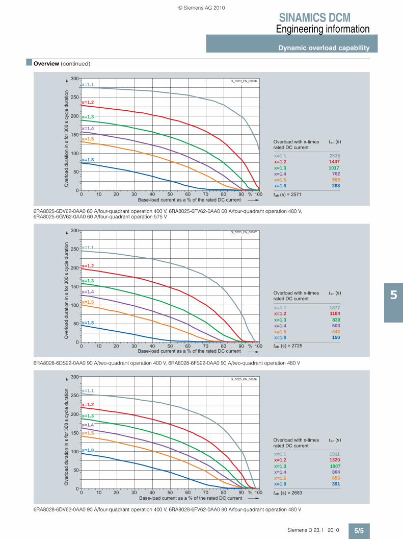
SINAMICS DCMEngineering information
Dynamic overload capability
5/5Siemens D 23.1 · 2010
5
■ Overview (continued)
6RA8025-6DV62-0AA0 60 A/four-quadrant operation 400 V, 6RA8025-6FV62-0AA0 60 A/four-quadrant operation 480 V, 6RA8025-6GV62-0AA0 60 A/four-quadrant operation 575 V
6RA8028-6DS22-0AA0 90 A/two-quadrant operation 400 V, 6RA8028-6FS22-0AA0 90 A/two-quadrant operation 480 V
6RA8028-6DV62-0AA0 90 A/four-quadrant operation 400 V, 6RA8028-6FV62-0AA0 90 A/four-quadrant operation 480 V
300
200
250
100
150
50
050403020100 100%90807060
x=1.1x=1.2x=1.3x=1.4x=1.5x=1.8
2536 14471017
762588283
x=1.1
x=1.2
x=1.3
x=1.4
x=1.5
x=1.8
Overload with x-timesrated DC current
(s)an
(s) = 2571ab
Ove
rload
dur
atio
n in
s fo
r 300
s c
ycle
dur
atio
n
Base-load current as a % of the rated DC current
G_D023_EN_00026
t
t
300
200
250
100
150
50
050403020100 100%90807060
x=1.1x=1.2x=1.3x=1.4x=1.5x=1.8
1877 1184 830603442150
x=1.1
x=1.2
x=1.3
x=1.4
x=1.5
x=1.8
Overload with x-timesrated DC current
(s)an
(s) = 2725ab
Ove
rload
dur
atio
n in
s fo
r 300
s c
ycle
dur
atio
n
Base-load current as a % of the rated DC current
G_D023_EN_00027
t
t
300
200
250
100
150
50
050403020100 100%90807060
x=1.1x=1.2x=1.3x=1.4x=1.5x=1.8
1911 1320
1007804659391
x=1.1
x=1.2
x=1.3
x=1.4x=1.5
x=1.8
Overload with x-timesrated DC current
(s)an
(s) = 2683ab
Ove
rload
dur
atio
n in
s fo
r 300
s c
ycle
dur
atio
n
Base-load current as a % of the rated DC current
G_D023_EN_00028
t
t
© Siemens AG 2010

SINAMICS DCMEngineering information
Dynamic overload capability
5/6 Siemens D 23.1 · 2010
5
■ Overview (continued)
6RA8031-6DS22-0AA0 125 A/two-quadrant operation 400 V, 6RA8031-6FS22-0AA0 125 A/two-quadrant operation 480 V, 6RA8031-6GS22-0AA0 125 A/two-quadrant operation 575 V
6RA8031-6DV62-0AA0 125 A/four-quadrant operation 400 V, 6RA8031-6FV62-0AA0 125 A/four-quadrant operation 480 V, 6RA8031-6GV62-0AA0 125 A/four-quadrant operation 575 V
6RA8075-6DS22-0AA0 210 A/two-quadrant operation 400 V, 6RA8075-6DV62-0AA0 210 A/four-quadrant operation 400 V, 6RA8075-6FS22-0AA0 210 A/two-quadrant operation 480 V, 6RA8075-6FV62-0AA0 210 A/four-quadrant operation 480 V, 6RA8075-6GS22-0AA0 210 A/two-quadrant operation 575 V, 6RA8075-6GV62-0AA0 210 A/four-quadrant operation 575 V
300
200
250
100
150
50
050403020100 100%90807060
x=1.1x=1.2x=1.3x=1.4x=1.5x=1.8
1994 1319
968743583289
x=1.1
x=1.2
x=1.3
x=1.4
x=1.5
x=1.8
Overload with x-timesrated DC current
(s)an
(s) = 2828ab
Ove
rload
dur
atio
n in
s fo
r 300
s c
ycle
dur
atio
n
Base-load current as a % of the rated DC current
G_D023_EN_00029
t
t
300
200
250
100
150
50
050403020100 100%90807060
x=1.1x=1.2x=1.3x=1.4x=1.5x=1.8
21591452
1078835662343
x=1.1
x=1.2
x=1.3
x=1.4
x=1.5
x=1.8
Overload with x-timesrated DC current
(s)an
(s) = 3158ab
Ove
rload
dur
atio
n in
s fo
r 300
s c
ycle
dur
atio
n
Base-load current as a % of the rated DC current
G_D023_EN_00030
t
t
300
200
250
100
150
50
050403020100 100%90807060
x=1.1x=1.2x=1.3x=1.4x=1.5x=1.8
68031816779251
x=1.1
x=1.2
x=1.3
x=1.4
x=1.5x=1.8
Overload with x-timesrated DC current
(s)an
(s) = 813ab
Ove
rload
dur
atio
n in
s fo
r 300
s c
ycle
dur
atio
n
Base-load current as a % of the rated DC current
G_D023_EN_00031
t
t
© Siemens AG 2010

SINAMICS DCMEngineering information
Dynamic overload capability
5/7Siemens D 23.1 · 2010
5
■ Overview (continued)
6RA8078-6DS22-0AA0 280 A/two-quadrant operation 400 V, 6RA8078-6DV62-0AA0 280 A/four-quadrant operation 400 V, 6RA8078-6FS22-0AA0 280 A/two-quadrant operation 480 V, 6RA8078-6FV62-0AA0 280 A/four-quadrant operation 480 V
6RA8081-6DS22-0AA0 400 A/two-quadrant operation 400 V, 6RA8081-6GS22-0AA0 400 A/two-quadrant operation 575 V
6RA8081-6DV62-0AA0 400 A/four-quadrant operation 400 V, 6RA8081-6GV62-0AA0 400 A/four-quadrant operation 575 V
300
200
250
100
150
50
050403020100 100%90807060
x=1.1x=1.2x=1.3x=1.4x=1.5x=1.8
729381
238156103
26
x=1.1
x=1.2
x=1.3
x=1.4
x=1.5
x=1.8
Overload with x-timesrated DC current
(s)an
(s) = 863ab
Ove
rload
dur
atio
n in
s fo
r 300
s c
ycle
dur
atio
n
Base-load current as a % of the rated DC current
G_D023_EN_00032
t
t
150
100
125
50
75
25
050403020100 100%90807060
x=1.1x=1.2x=1.3x=1.4x=1.5x=1.8
132 55 23
941
x=1.1
x=1.2
x=1.3
x=1.4x=1.5x=1.8
Overload with x-timesrated DC current
(s)an
(s) = 203ab
Ove
rload
dur
atio
n in
s fo
r 300
s c
ycle
dur
atio
n
Base-load current as a % of the rated DC current
G_D023_EN_00033
t
t
300
200
250
100
150
50
050403020100 100%90807060
x=1.1x=1.2x=1.3x=1.4x=1.5x=1.8
265 108
451251
x=1.1
x=1.2
x=1.3
x=1.4 x=1.5 x=1.8
Overload with x-timesrated DC current
(s)an
(s) = 367ab
Ove
rload
dur
atio
n in
s fo
r 300
s c
ycle
dur
atio
n
Base-load current as a % of the rated DC current
G_D023_EN_00034
t
t
© Siemens AG 2010

SINAMICS DCMEngineering information
Dynamic overload capability
5/8 Siemens D 23.1 · 2010
5
■ Overview (continued)
6RA8082-6FS22-0AA0 450 A/two-quadrant operation 480 V, 6RA8082-6FV62-0AA0 450 A/four-quadrant operation 480 V
6RA8085-6DS22-0AA0 600 A/two-quadrant operation 400 V, 6RA8085-6FS22-0AA0 600 A/two-quadrant operation 480 V, 6RA8085-6GS22-0AA0 600 A/two-quadrant operation 575 V
6RA8085-6DV62-0AA0 600 A/four-quadrant operation 400 V, 6RA8085-6FV62-0AA0 600 A/four-quadrant operation 480 V, 6RA8085-6GV62-0AA0 600 A/four-quadrant operation 575 V
25
050403020100 100%90807060
x=1.1x=1.2x=1.3x=1.4x=1.5x=1.8
110 49 22
1161
x=1.1
x=1.2
x=1.3
150
100
125
50
75
x=1.8x=1.5 x=1.4
Overload with x-timesrated DC current
(s)an
(s) = 210ab
Ove
rload
dur
atio
n in
s fo
r 300
s c
ycle
dur
atio
n
Base-load current as a % of the rated DC current
G_D023_EN_00035
t
t
300
200
250
100
150
50
050403020100 100%90807060
x=1.1x=1.2x=1.3x=1.4x=1.5x=1.8
331 137
754529
7
x=1.1
x=1.2
x=1.3
x=1.4 x=1.5
x=1.8
Overload with x-timesrated DC current
(s)an
(s) = 408ab
Ove
rload
dur
atio
n in
s fo
r 300
s c
ycle
dur
atio
n
Base-load current as a % of the rated DC current
G_D023_EN_00036
t
t
300
200
250
100
150
50
050403020100 100%90807060
x=1.1x=1.2x=1.3x=1.4x=1.5x=1.8
426 184 107
6437
5
x=1.1
x=1.2
x=1.3
x=1.4
x=1.5
x=1.8
Overload with x-timesrated DC current
(s)an
(s) = 519ab
Ove
rload
dur
atio
n in
s fo
r 300
s c
ycle
dur
atio
n
Base-load current as a % of the rated DC current
G_D023_EN_00037
t
t
© Siemens AG 2010

SINAMICS DCMEngineering information
Dynamic overload capability
5/9Siemens D 23.1 · 2010
5
■ Overview (continued)
6RA8086-6KS22-0AA0 720 A/two-quadrant operation 690 V
6RA8086-6KV62-0AA0 760 A/four-quadrant operation 690 V
6RA8087-6DS22-0AA0 850 A/two-quadrant operation 400 V, 6RA8087-6FS22-0AA0 850 A/two-quadrant operation 480 V
300
200
250
100
150
50
050403020100 100%90807060
x=1.1x=1.2x=1.3x=1.4x=1.5x=1.8
312 170 109
755522
x=1.1
x=1.2
x=1.3
x=1.4 x=1.5
x=1.8
Overload with x-timesrated DC current
(s)an
(s) = 542ab
Ove
rload
dur
atio
n in
s fo
r 300
s c
ycle
dur
atio
n
Base-load current as a % of the rated DC current
G_D023_EN_00038
t
t
300
200
250
100
150
50
050403020100 100%90807060
x=1.1x=1.2x=1.3x=1.4x=1.5x=1.8
411 245 164
1137920
x=1.1
x=1.2
x=1.3
x=1.4
x=1.5
x=1.8
Overload with x-timesrated DC current
(s)an
(s) = 606ab
Ove
rload
dur
atio
n in
s fo
r 300
s c
ycle
dur
atio
n
Base-load current as a % of the rated DC current
G_D023_EN_00039
t
t
300
200
250
100
150
50
050403020100 100%90807060
x=1.1x=1.2x=1.3x=1.4x=1.5x=1.8
316 175
114805825
x=1.1
x=1.2
x=1.3
x=1.4 x=1.5
x=1.8
Overload with x-timesrated DC current
(s)an
(s) = 542ab
Ove
rload
dur
atio
n in
s fo
r 300
s c
ycle
dur
atio
n
Base-load current as a % of the rated DC current
G_D023_EN_00040
t
t
© Siemens AG 2010

SINAMICS DCMEngineering information
Dynamic overload capability
5/10 Siemens D 23.1 · 2010
5
■ Overview (continued)
6RA8087-6DV62-0AA0 850 A/four-quadrant operation 400 V, 6RA8087-6FV62-0AA0 850 A/four-quadrant operation 480 V, 6RA8087-6GV62-0AA0 850 A/four-quadrant operation 575 V
6RA8087-6GS22-0AA0 800 A/two-quadrant operation 575 V
6RA8088-6LS22-0AA0 950 A/two-quadrant operation 830 V, 6RA8088-6LV62-0AA0 950 A/four-quadrant operation 830 V
300
200
250
100
150
50
050403020100 100%90807060
x=1.1x=1.2x=1.3x=1.4x=1.5x=1.8
382 228 1511026813
x=1.1
x=1.2
x=1.3
x=1.4
x=1.5
x=1.8
Overload with x-timesrated DC current
(s)an
(s) = 593ab
Ove
rload
dur
atio
n in
s fo
r 300
s c
ycle
dur
atio
n
Base-load current as a % of the rated DC current
G_D023_EN_00041
t
t
300
200
250
100
150
50
050403020100 100%90807060
x=1.1x=1.2x=1.3x=1.4x=1.5x=1.8
296 161 102
705019
x=1.1
x=1.2
x=1.3
x=1.4 x=1.5
x=1.8
Overload with x-timesrated DC current
(s)an
(s) = 527ab
Ove
rload
dur
atio
n in
s fo
r 300
s c
ycle
dur
atio
n
Base-load current as a % of the rated DC current
G_D023_EN_00042
t
t
300
200
250
100
150
50
050403020100 100%90807060
x=1.1x=1.2x=1.3x=1.4x=1.5x=1.8
220 99 5025134
x=1.1
x=1.2
x=1.3
x=1.4x=1.5 x=1.8
Overload with x-timesrated DC current
(s)an
(s) = 395ab
Ove
rload
dur
atio
n in
s fo
r 300
s c
ycle
dur
atio
n
Base-load current as a % of the rated DC current
G_D023_EN_00043
t
t
© Siemens AG 2010

SINAMICS DCMEngineering information
Dynamic overload capability
5/11Siemens D 23.1 · 2010
5
■ Overview (continued)
6RA8090-6GS22-0AA0 1 100 A/two-quadrant operation 575 V, 6RA8090-6GV62-0AA0 1 100 A/four-quadrant operation 575 V
6RA8090-6KS22-0AA0 1 000 A/two-quadrant operation 690 V, 6RA8090-6KV62-0AA0 1 000 A/four-quadrant operation 690 V
6RA8091-6DS22-0AA0 1 200 A/two-quadrant operation 400 V, 6RA8091-6FS22-0AA0 1 200 A/two-quadrant operation 480 V, 6RA8091-6FV62-0AA0 1 200 A/four-quadrant operation 480 V, 6RA8091-6DV62-0AA0 1 200 A/four-quadrant operation 400 V
150
100
125
50
75
25
050403020100 100%90807060
x=1.1x=1.2x=1.3x=1.4x=1.5x=1.8
208 91 43
20103
x=1.1
x=1.2
x=1.3
x=1.4x=1.5x=1.8
Overload with x-timesrated DC current
(s)an
(s) = 380ab
Ove
rload
dur
atio
n in
s fo
r 300
s c
ycle
dur
atio
n
Base-load current as a % of the rated DC current
G_D023_EN_00044
t
t
300
200
250
100
150
50
050403020100 100%90807060
x=1.1x=1.2x=1.3x=1.4x=1.5x=1.8
219 99 502513
4
x=1.1
x=1.2
x=1.3x=1.4
x=1.5 x=1.8
Overload with x-timesrated DC current
(s)an
(s) = 395ab
Ove
rload
dur
atio
n in
s fo
r 300
s c
ycle
dur
atio
n
Base-load current as a % of the rated DC current
G_D023_EN_00045
t
t
300
200
250
100
150
50
050403020100 100%90807060
x=1.1x=1.2x=1.3x=1.4x=1.5x=1.8
223 104
5428154
x=1.1
x=1.2
x=1.3x=1.4
x=1.5 x=1.8
Overload with x-timesrated DC current
(s)an
(s) = 395ab
Ove
rload
dur
atio
n in
s fo
r 300
s c
ycle
dur
atio
n
Base-load current as a % of the rated DC current
G_D023_EN_00046
t
t
© Siemens AG 2010

SINAMICS DCMEngineering information
Dynamic overload capability
5/12 Siemens D 23.1 · 2010
5
■ Overview (continued)
6RA8093-4DS22-0AA0 1 600 A/two-quadrant operation 400 V, 6RA8093-4DV62-0AA0 1 600 A/four-quadrant operation 400 V, 6RA8093-4GS22-0AA0 1 600 A/two-quadrant operation 575 V, 6RA8093-4GV62-0AA0 1 600 A/four-quadrant operation 575 V
6RA8093-4KS22-0AA0 1 500 A/two-quadrant operation 690 V, 6RA8093-4KV62-0AA0 1 500 A/four-quadrant operation 690 V, 6RA8093-4LS22-0AA0 1 500 A/two-quadrant operation 830 V, 6RA8093-4LV62-0AA0 1 500 A/four-quadrant operation 830 V
6RA8095-4DS22-0AA0 2 000 A/two-quadrant operation 400 V, 6RA8095-4DV62-0AA0 2 000 A/four-quadrant operation 400 V
300
200
250
100
150
50
050403020100 100%90807060
x=1.1x=1.2x=1.3x=1.4x=1.5x=1.8
519 221 123
744615
x=1.1
x=1.2
x=1.3
x=1.4x=1.5
x=1.8
Overload with x-timesrated DC current
(s)an
(s) = 591ab
Ove
rload
dur
atio
n in
s fo
r 300
s c
ycle
dur
atio
n
Base-load current as a % of the rated DC current
G_D023_EN_00048
t
t
300
200
250
100
150
50
050403020100 100%90807060
x=1.1x=1.2x=1.3x=1.4x=1.5x=1.8
546 196
9247278
x=1.1
x=1.2
x=1.3
x=1.4x=1.5x=1.8
Overload with x-timesrated DC current
(s)an
(s) = 499ab
Ove
rload
dur
atio
n in
s fo
r 300
s c
ycle
dur
atio
n
Base-load current as a % of the rated DC current
G_D023_EN_00049
t
t
300
200
250
100
150
50
050403020100 100%90807060
x=1.1x=1.2x=1.3x=1.4x=1.5x=1.8
274 129
6637248
x=1.1
x=1.2
x=1.3x=1.4
x=1.5 x=1.8
Overload with x-timesrated DC current
(s)an
(s) = 517ab
Ove
rload
dur
atio
n in
s fo
r 300
s c
ycle
dur
atio
n
Base-load current as a % of the rated DC current
G_D023_EN_00050
t
t
© Siemens AG 2010

SINAMICS DCMEngineering information
Dynamic overload capability
5/13Siemens D 23.1 · 2010
5
■ Overview (continued)
6RA8095-4GS22-0AA0 2 000 A/two-quadrant operation 575 V, 6RA8095-4GV62-0AA0 2 000 A/four-quadrant operation 575 V
6RA8095-4KS22-0AA0 2 000 A/two-quadrant operation 690 V, 6RA8095-4KV62-0AA0 2 000 A/four-quadrant operation 690 V
6RA8095-4LS22-0AA0 1 900 A/two-quadrant operation 830 V, 6RA8095-4LV62-0AA0 1 900 A/four-quadrant operation 830 V
300
200
250
100
150
50
050403020100 100%90807060
x=1.1x=1.2x=1.3x=1.4x=1.5x=1.8
1247 421 24215911247
x=1.1
x=1.2
x=1.3
x=1.4x=1.5
x=1.8
Overload with x-timesrated DC current
(s)an
(s) = 1099ab
Ove
rload
dur
atio
n in
s fo
r 300
s c
ycle
dur
atio
n
Base-load current as a % of the rated DC current
G_D023_EN_00051
t
t
300
200
250
100
150
50
050403020100 100%90807060
x=1.1x=1.2x=1.3x=1.4x=1.5x=1.8
480 248 1561057329
x=1.1
x=1.2
x=1.3
x=1.4x=1.5
x=1.8
Overload with x-timesrated DC current
(s)an
(s) = 676ab
Ove
rload
dur
atio
n in
s fo
r 300
s c
ycle
dur
atio
n
Base-load current as a % of the rated DC current
G_D023_EN_00052
t
t
300
200
250
100
150
50
050403020100 100%90807060
x=1.1x=1.2x=1.3x=1.4x=1.5x=1.8
514 259 161108
7631
x=1.1
x=1.2
x=1.3
x=1.4x=1.5
x=1.8
Overload with x-timesrated DC current
(s)an
(s) = 1099ab
Ove
rload
dur
atio
n in
s fo
r 300
s c
ycle
dur
atio
n
Base-load current as a % of the rated DC current
G_D023_EN_00053
t
t
© Siemens AG 2010
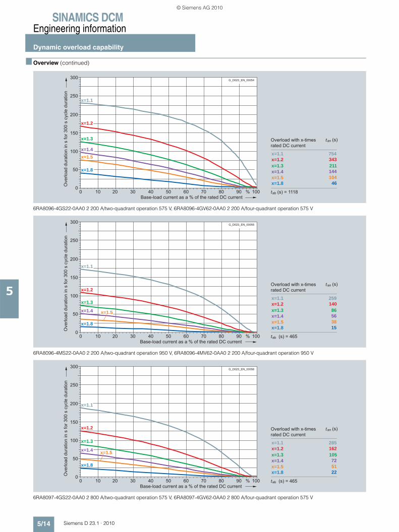
SINAMICS DCMEngineering information
Dynamic overload capability
5/14 Siemens D 23.1 · 2010
5
■ Overview (continued)
6RA8096-4GS22-0AA0 2 200 A/two-quadrant operation 575 V, 6RA8096-4GV62-0AA0 2 200 A/four-quadrant operation 575 V
6RA8096-4MS22-0AA0 2 200 A/two-quadrant operation 950 V, 6RA8096-4MV62-0AA0 2 200 A/four-quadrant operation 950 V
6RA8097-4GS22-0AA0 2 800 A/two-quadrant operation 575 V, 6RA8097-4GV62-0AA0 2 800 A/four-quadrant operation 575 V
300
200
250
100
150
50
050403020100 100%90807060
x=1.1x=1.2x=1.3x=1.4x=1.5x=1.8
754 343 211144104
46
x=1.1
x=1.2
x=1.3
x=1.4x=1.5
x=1.8
Overload with x-timesrated DC current
(s)an
(s) = 1118ab
Ove
rload
dur
atio
n in
s fo
r 300
s c
ycle
dur
atio
n
Base-load current as a % of the rated DC current
G_D023_EN_00054
t
t
300
200
250
100
150
50
050403020100 100%90807060
x=1.1x=1.2x=1.3x=1.4x=1.5x=1.8
259 140 86
563815
x=1.1
x=1.2
x=1.3
x=1.4 x=1.5
x=1.8
Overload with x-timesrated DC current
(s)an
(s) = 465ab
Ove
rload
dur
atio
n in
s fo
r 300
s c
ycle
dur
atio
n
Base-load current as a % of the rated DC current
G_D023_EN_00055
t
t
300
200
250
100
150
50
050403020100 100%90807060
x=1.1x=1.2x=1.3x=1.4x=1.5x=1.8
285 162 105
725122
x=1.1
x=1.2
x=1.3
x=1.4 x=1.5
x=1.8
Overload with x-timesrated DC current
(s)an
(s) = 465ab
Ove
rload
dur
atio
n in
s fo
r 300
s c
ycle
dur
atio
n
Base-load current as a % of the rated DC current
G_D023_EN_00056
t
t
© Siemens AG 2010

SINAMICS DCMEngineering information
Dynamic overload capability
5/15Siemens D 23.1 · 2010
5
■ Overview (continued)
6RA8097-4KS22-0AA0 2 600 A/two-quadrant operation 690 V, 6RA8097-4KV62-0AA0 2 600 A/four-quadrant operation 690 V
6RA8098-4DS22-0AA0 3 000 A/two-quadrant operation 400 V, 6RA8098-4DV62-0AA0 3 000 A/four-quadrant operation 400 V
Load classes
In order to be able to adapt the SINAMICS DC MASTER as sim-ply as possible to the load profile of the driven machine, in addi-tion to the individual dimensioning using the limiting characteris-tics of the dynamic overload capability, these can also be dimensioned using pre-selected load cycles that are simple to parameterize.
Note:
SINAMICS DC MASTER does not monitor whether the load class – set using parameters – is maintained. If the power section per-mits it, the unit can operate for overload durations in excess of those defined by the load class. This means that the driven ma-chine of the mechanical system is not protected against over-load!
The overload duration that is actually permitted for the power section in question is always longer than the duration defined by the load class. SINAMICS DC MASTER monitors whether the overload duration that is actually permitted for the power section is being maintained.
300
200
250
100
150
50
050403020100 100%90807060
x=1.1x=1.2x=1.3x=1.4x=1.5x=1.8
296 168 109
745323
x=1.1
x=1.2
x=1.3
x=1.4 x=1.5
x=1.8
Overload with x-timesrated DC current
(s)an
(s) = 465ab
Ove
rload
dur
atio
n in
s fo
r 300
s c
ycle
dur
atio
n
Base-load current as a % of the rated DC current
G_D023_EN_00057
t
t
300
200
250
100
150
50
050403020100 100%90807060
x=1.1x=1.2x=1.3x=1.4x=1.5x=1.8
282 160 103
705021
x=1.1
x=1.2
x=1.3
x=1.4 x=1.5
x=1.8
Overload with x-timesrated DC current
(s)an
(s) = 465ab
Ove
rload
dur
atio
n in
s fo
r 300
s c
ycle
dur
atio
n
Base-load current as a % of the rated DC current
G_D023_EN_00058
t
t
© Siemens AG 2010
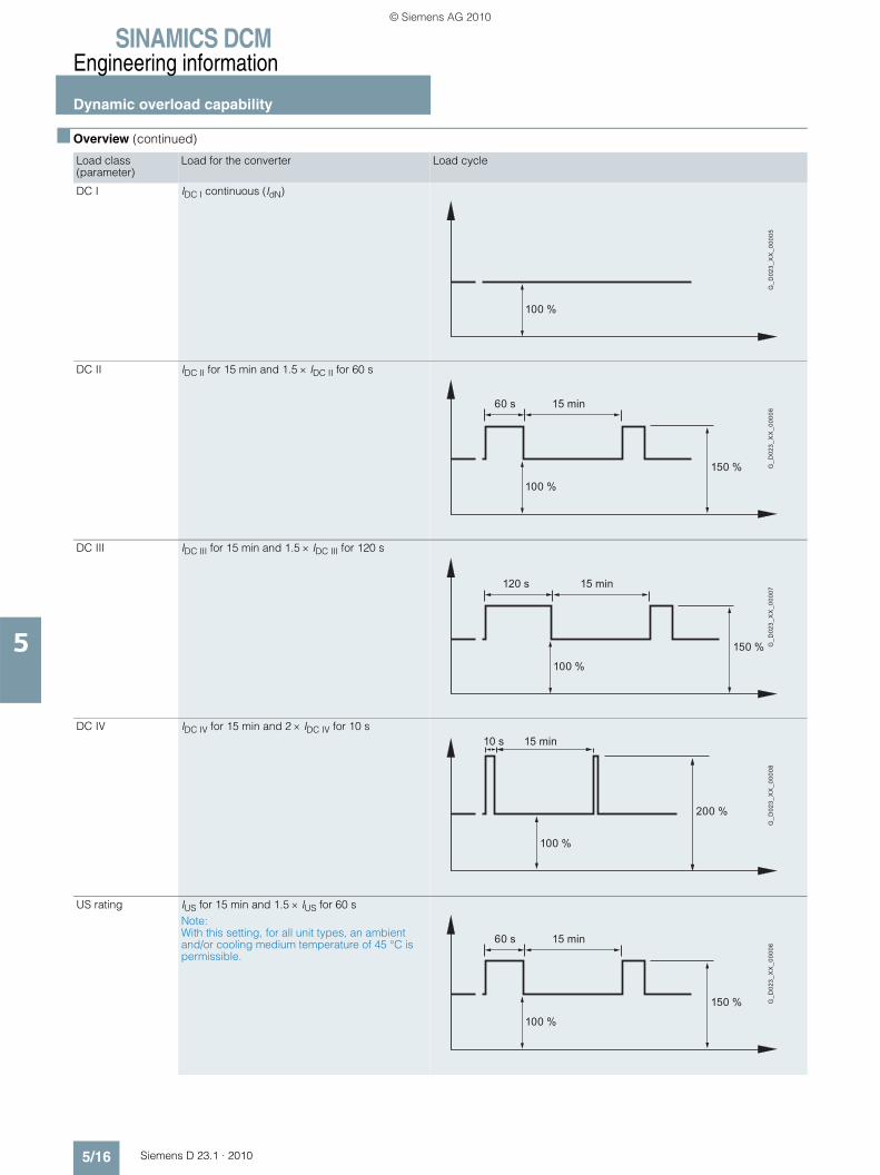
SINAMICS DCMEngineering information
Dynamic overload capability
5/16 Siemens D 23.1 · 2010
5
■ Overview (continued)
Load class (parameter)
Load for the converter Load cycle
DC I IDC I continuous (IdN)
DC II IDC II for 15 min and 1.5 × IDC II for 60 s
DC III IDC III for 15 min and 1.5 × IDC III for 120 s
DC IV IDC IV for 15 min and 2 × IDC IV for 10 s
US rating IUS for 15 min and 1.5 × IUS for 60 sNote: With this setting, for all unit types, an ambient and/or cooling medium temperature of 45 °C is permissible.
100 %
G_D
023_
XX
_000
05
15 min60 s
150 %
100 %
G_D
023_
XX
_000
06
15 min120 s
150 %
100 %
G_D
023_
XX
_000
07
15 min10 s
200 %
100 %
G_D
023_
XX
_000
08
15 min60 s
150 %
100 %
G_D
023_
XX
_000
06
© Siemens AG 2010
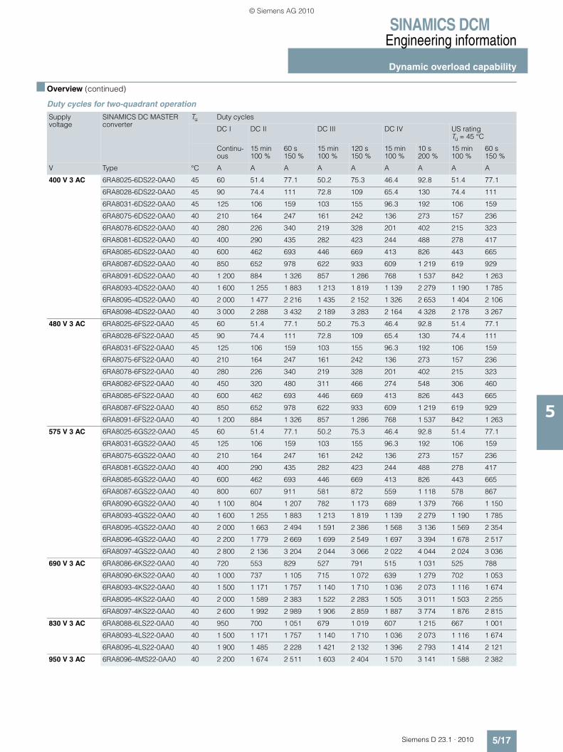
SINAMICS DCMEngineering information
Dynamic overload capability
5/17Siemens D 23.1 · 2010
5
■ Overview (continued)
Duty cycles for two-quadrant operation
Supply voltage
SINAMICS DC MASTER converter
Tu Duty cycles
DC I DC II DC III DC IV US rating Tu = 45 °C
Continu-ous
15 min 100 %
60 s 150 %
15 min 100 %
120 s 150 %
15 min 100 %
10 s 200 %
15 min 100 %
60 s 150 %
V Type °C A A A A A A A A A
400 V 3 AC 6RA8025-6DS22-0AA0 45 60 51.4 77.1 50.2 75.3 46.4 92.8 51.4 77.1
6RA8028-6DS22-0AA0 45 90 74.4 111 72.8 109 65.4 130 74.4 111
6RA8031-6DS22-0AA0 45 125 106 159 103 155 96.3 192 106 159
6RA8075-6DS22-0AA0 40 210 164 247 161 242 136 273 157 236
6RA8078-6DS22-0AA0 40 280 226 340 219 328 201 402 215 323
6RA8081-6DS22-0AA0 40 400 290 435 282 423 244 488 278 417
6RA8085-6DS22-0AA0 40 600 462 693 446 669 413 826 443 665
6RA8087-6DS22-0AA0 40 850 652 978 622 933 609 1 219 619 929
6RA8091-6DS22-0AA0 40 1 200 884 1 326 857 1 286 768 1 537 842 1 263
6RA8093-4DS22-0AA0 40 1 600 1 255 1 883 1 213 1 819 1 139 2 279 1 190 1 785
6RA8095-4DS22-0AA0 40 2 000 1 477 2 216 1 435 2 152 1 326 2 653 1 404 2 106
6RA8098-4DS22-0AA0 40 3 000 2 288 3 432 2 189 3 283 2 164 4 328 2 178 3 267
480 V 3 AC 6RA8025-6FS22-0AA0 45 60 51.4 77.1 50.2 75.3 46.4 92.8 51.4 77.1
6RA8028-6FS22-0AA0 45 90 74.4 111 72.8 109 65.4 130 74.4 111
6RA8031-6FS22-0AA0 45 125 106 159 103 155 96.3 192 106 159
6RA8075-6FS22-0AA0 40 210 164 247 161 242 136 273 157 236
6RA8078-6FS22-0AA0 40 280 226 340 219 328 201 402 215 323
6RA8082-6FS22-0AA0 40 450 320 480 311 466 274 548 306 460
6RA8085-6FS22-0AA0 40 600 462 693 446 669 413 826 443 665
6RA8087-6FS22-0AA0 40 850 652 978 622 933 609 1 219 619 929
6RA8091-6FS22-0AA0 40 1 200 884 1 326 857 1 286 768 1 537 842 1 263
575 V 3 AC 6RA8025-6GS22-0AA0 45 60 51.4 77.1 50.2 75.3 46.4 92.8 51.4 77.1
6RA8031-6GS22-0AA0 45 125 106 159 103 155 96.3 192 106 159
6RA8075-6GS22-0AA0 40 210 164 247 161 242 136 273 157 236
6RA8081-6GS22-0AA0 40 400 290 435 282 423 244 488 278 417
6RA8085-6GS22-0AA0 40 600 462 693 446 669 413 826 443 665
6RA8087-6GS22-0AA0 40 800 607 911 581 872 559 1 118 578 867
6RA8090-6GS22-0AA0 40 1 100 804 1 207 782 1 173 689 1 379 766 1 150
6RA8093-4GS22-0AA0 40 1 600 1 255 1 883 1 213 1 819 1 139 2 279 1 190 1 785
6RA8095-4GS22-0AA0 40 2 000 1 663 2 494 1 591 2 386 1 568 3 136 1 569 2 354
6RA8096-4GS22-0AA0 40 2 200 1 779 2 669 1 699 2 549 1 697 3 394 1 678 2 517
6RA8097-4GS22-0AA0 40 2 800 2 136 3 204 2 044 3 066 2 022 4 044 2 024 3 036
690 V 3 AC 6RA8086-6KS22-0AA0 40 720 553 829 527 791 515 1 031 525 788
6RA8090-6KS22-0AA0 40 1 000 737 1 105 715 1 072 639 1 279 702 1 053
6RA8093-4KS22-0AA0 40 1 500 1 171 1 757 1 140 1 710 1 036 2 073 1 116 1 674
6RA8095-4KS22-0AA0 40 2 000 1 589 2 383 1 522 2 283 1 505 3 011 1 503 2 255
6RA8097-4KS22-0AA0 40 2 600 1 992 2 989 1 906 2 859 1 887 3 774 1 876 2 815
830 V 3 AC 6RA8088-6LS22-0AA0 40 950 700 1 051 679 1 019 607 1 215 667 1 001
6RA8093-4LS22-0AA0 40 1 500 1 171 1 757 1 140 1 710 1 036 2 073 1 116 1 674
6RA8095-4LS22-0AA0 40 1 900 1 485 2 228 1 421 2 132 1 396 2 793 1 414 2 121
950 V 3 AC 6RA8096-4MS22-0AA0 40 2 200 1 674 2 511 1 603 2 404 1 570 3 141 1 588 2 382
© Siemens AG 2010
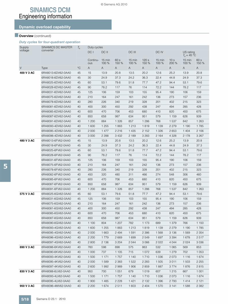
SINAMICS DCMEngineering information
Dynamic overload capability
5/18 Siemens D 23.1 · 2010
5
■ Overview (continued)
Duty cycles for four-quadrant operation
Supply voltage
SINAMICS DC MASTER converter
Tu Duty cycles
DC I DC II DC III DC IV US rating Tu = 45 °C
Continu-ous
15 min 100 %
60 s 150 %
15 min 100 %
120 s 150 %
15 min 100 %
10 s 200 %
15 min 100 %
60 s 150 %
V Type °C A A A A A A A A A
400 V 3 AC 6RA8013-6DV62-0AA0 45 15 13.9 20.8 13.5 20.2 12.6 25.2 13.9 20.8
6RA8018-6DV62-0AA0 45 30 24.9 37.3 24.2 36.3 22.4 44.8 24.9 37.3
6RA8025-6DV62-0AA0 45 60 53.1 79.6 51.8 77.7 47.2 94.4 53.1 79.6
6RA8028-6DV62-0AA0 45 90 78.2 117 76 114 72.2 144 78.2 117
6RA8031-6DV62-0AA0 45 125 106 159 103 155 95.4 190 106 159
6RA8075-6DV62-0AA0 40 210 164 247 161 242 136 273 157 236
6RA8078-6DV62-0AA0 40 280 226 340 219 328 201 402 215 323
6RA8081-6DV62-0AA0 40 400 300 450 292 438 247 494 285 428
6RA8085-6DV62-0AA0 40 600 470 706 453 680 410 820 450 675
6RA8087-6DV62-0AA0 40 850 658 987 634 951 579 1 159 626 939
6RA8091-6DV62-0AA0 40 1 200 884 1 326 857 1 286 768 1 537 842 1 263
6RA8093-4DV62-0AA0 40 1 600 1 255 1 883 1 213 1 819 1 139 2 279 1 190 1 785
6RA8095-4DV62-0AA0 40 2 000 1 477 2 216 1 435 2 152 1 326 2 653 1 404 2 106
6RA8098-4DV62-0AA0 40 3 000 2 288 3 432 2 189 3 283 2 164 4 328 2 178 3 267
480 V 3 AC 6RA8013-6FV62-0AA0 45 15 13.9 20.8 13.5 20.2 12.6 25.2 13.9 20.8
6RA8018-6FV62-0AA0 45 30 24.9 37.3 24.2 36.3 22.4 44.8 24.9 37.3
6RA8025-6FV62-0AA0 45 60 53.1 79.6 51.8 77.7 47.2 94.4 53.1 79.6
6RA8028-6FV62-0AA0 45 90 78.2 117 76 114 72.2 144 78.2 117
6RA8031-6FV62-0AA0 45 125 106 159 103 155 95.4 190 106 159
6RA8075-6FV62-0AA0 40 210 164 247 161 242 136 273 157 236
6RA8078-6FV62-0AA0 40 280 226 340 219 328 201 402 215 323
6RA8082-6FV62-0AA0 40 450 320 480 311 466 274 548 306 460
6RA8085-6FV62-0AA0 40 600 470 706 453 680 410 820 450 675
6RA8087-6FV62-0AA0 40 850 658 987 634 951 579 1 159 626 939
6RA8091-6FV62-0AA0 40 1 200 884 1 326 857 1 286 768 1 537 842 1 263
575 V 3 AC 6RA8025-6GV62-0AA0 45 60 53.1 79.6 51.8 77.7 47.2 94.4 53.1 79.6
6RA8031-6GV62-0AA0 45 125 106 159 103 155 95.4 190 106 159
6RA8075-6GV62-0AA0 40 210 164 247 161 242 136 273 157 236
6RA8081-6GV62-0AA0 40 400 300 450 292 438 247 494 285 428
6RA8085-6GV62-0AA0 40 600 470 706 453 680 410 820 450 675
6RA8087-6GV62-0AA0 40 850 658 987 634 951 579 1 159 626 939
6RA8090-6GV62-0AA0 40 1 100 804 1 207 782 1 173 689 1 379 766 1 150
6RA8093-4GV62-0AA0 40 1 600 1 255 1 883 1 213 1 819 1 139 2 279 1 190 1 785
6RA8095-4GV62-0AA0 40 2 000 1 663 2 494 1 591 2 386 1 568 3 136 1 569 2 354
6RA8096-4GV62-0AA0 40 2 200 1 779 2 669 1 699 2 549 1 697 3 394 1 678 2 517
6RA8097-4GV62-0AA0 40 2 800 2 136 3 204 2 044 3 066 2 022 4 044 2 024 3 036
690 V 3 AC 6RA8086-6KV62-0AA0 40 760 598 898 575 863 532 1 065 569 853
6RA8090-6KV62-0AA0 40 1 000 737 1 105 715 1 072 639 1 279 702 1 053
6RA8093-4KV62-0AA0 40 1 500 1 171 1 757 1 140 1 710 1 036 2 073 1 116 1 674
6RA8095-4KV62-0AA0 40 2 000 1 589 2 383 1 522 2 283 1 505 3 011 1 503 2 255
6RA8097-4KV62-0AA0 40 2 600 1 992 2 989 1 906 2 859 1 887 3 774 1 876 2 815
830 V 3 AC 6RA8088-6LV62-0AA0 40 950 700 1 051 679 1 019 607 1 215 667 1 001
6RA8093-4LV62-0AA0 40 1 500 1 171 1 757 1 140 1 710 1 036 2 073 1 116 1 674
6RA8095-4LV62-0AA0 40 1 900 1 485 2 228 1 421 2 132 1 396 2 793 1 414 2 121
950 V 3 AC 6RA8096-4MV62-0AA0 40 2 200 1 674 2 511 1 603 2 404 1 570 3 141 1 588 2 382
© Siemens AG 2010
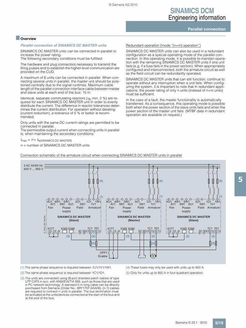
SINAMICS DCMEngineering information
Parallel connection
5/19Siemens D 23.1 · 2010
5
■ Overview
Parallel connection of SINAMICS DC MASTER units
SINAMICS DC MASTER units can be connected in parallel to increase the power rating. The following secondary conditions must be fulfilled:
The hardware and plug connectors necessary to transmit the firing pulses and to establish the higher-level communication are provided on the CUD.
A maximum of 6 units can be connected in parallel. When con-necting several units in parallel, the master unit should be posi-tioned centrally due to the signal runtimes. Maximum cable length of the parallel-connection interface cable between master and slave units at each end of the bus: 15 m.
Identical, separate commutating reactors (uK min. 2 %) are re-quired for each SINAMICS DC MASTER unit in order to evenly distribute the current. The difference in reactor tolerances deter-mines the current distribution. For operation without derating (current reduction), a tolerance of 5 % or better is recom-mended.
Only units with the same DC current ratings are permitted to be connected in parallel. The permissible output current when connecting units in parallel is, when maintaining the secondary conditions:
Imax = n × IN(SINAMICS DC MASTER)
n = number of SINAMICS DC MASTER units
Redundant operation (mode “(n+m) operation”)
SINAMICS DC MASTER units can also be used in a redundant configuration as a special operating mode of the parallel con-nection. In this operating mode, it is possible to maintain opera-tion with the remaining SINAMICS DC MASTER units if one unit fails (e.g. if a fuse fails in the power section). When appropriately configured and interconnected, both the armature circuit as well as the field circuit can be redundantly operated.
SINAMICS DC MASTER units that can still function, continue to operate without any interruption when a unit fails. When config-uring the system, it is important to note that in redundant appli-cations, the power rating of only n units (instead of n+m units) must be sufficient.
In the case of a fault, the master functionality is automatically transferred. As a consequence, this operating mode is possible both when the power section of the slave units fails and when the power section of the master unit fails. (MTBF data in redundant operation are available on request.)
Connection schematic of the armature circuit when connecting SINAMICS DC MASTER units in parallel
(1) The same phase sequence is required between 1U1/1V1/1W1.
(2) The same phase sequence is required between 1C1/1D1.
(3) The units are connected using (8-pin) shielded patch cables of type UTP CAT5 in acc. with ANSI/EIA/TIA 568, such as those that are used in PC network technology. A standard 5 m long cable can be directly purchased from Siemens (Order No.: 6RY1707-0AA08). (n-1) cables are required to connect n units in parallel. The bus termination must be activated at the units/devices connected at the start of the bus and at the end of the bus.
(4) These fuses may only be used with units up to 850 A.
(5) Only for units up to 850 A in four-quadrant operation.
3 AC 50/60 Hz 400 V ... 950 V
4U1
X165X177-13 -12 -9
X166 X165 X166 X165 X1663C 3D(1D1)
1C1 1D13C 3D(1D1)
1C1 1D13C 3D(1D1)(1C1)
1C1 1D1
4V14W1
5N15W1
5U13U1
3W11U1
1V11W1 4U1
4V14W1
5N15W1
5U13U1
3W11U1
1V11W1 4U1
4V14W1
5N15W1
5U13U1
3W11U1
1V11W1
SINAMICS DC MASTER(Slave)
SINAMICS DC MASTER(Slave)
SINAMICS DC MASTER (Master)
Fan Field ArmaturePower supply
Power supply
Power supply
Fan Field Armature Fan Field Armature
X177-13 -12 -9
X177-13 -12 -9(1C1) (1C1)
OFF1Enable
G_D
023_
EN
_000
09a
(5)
(2)(3)
(5)
(2)
(5)
(2) (3)(3)
(1) (1) (1)
(4)(4)(4)
M
© Siemens AG 2010

SINAMICS DCMEngineering information
12-pulse operation
5/20 Siemens D 23.1 · 2010
5
■ Overview
SINAMICS DC MASTER for 12-pulse operation
For 12-pulse operation, two SINAMICS DC MASTER converters are supplied with voltages displaced by 30 degrees. This con-figuration reduces the harmonics. Each SINAMICS DC MASTER conducts half of the total current. One of the SINAMICS DC MASTER units is operated with closed-loop speed control, and the second with closed-loop current control. A peer-to-peer connection is used to transfer the current setpoint from the first to the second SINAMICS DC MASTER.
Smoothing reactors are required in the DC circuit for 12-pulse operation.
Calculating the smoothing reactor• A smoothing reactor is used for each of the two partial con-
verters. The reactor comprises a 2-value reactor; this means that the inductance of the reactor is defined for two current values.
• The reactor is thermally dimensioned according to the rms value of the DC reactor current.
Calculating the required inductance
1. Inductance of the reactor at 0.2 × IdN (LD1)
2. Inductance of the reactor for Idmax (LD2)• Inductance for 50 Hz line frequency
LD1 = 0.296 × 10⁻³ × Vdi/(0.2 × IdN)
LD2 = 0.296 × 10⁻³ × Vdi/(0.33 × Idmax)
• Inductance for 60 Hz line frequency
LD1 = 0.24 × 10⁻³ × Vdi/(0.2 × IdN)
LD2 = 0.24 × 10⁻³ × Vdi/(0.33 × Idmax)
L = Inductance in H
IdN half the rated DC current of the DC motor
Idmax half the maximum current of the DC motor
Vdi = 1.35 × VN
VN rated line supply voltage
12-pulse operation
■ Overview
SINAMICS DC MASTER to supply high inductances
To supply high inductances – such as the fields of large DC or synchronous motors or lifting solenoids – the gating unit is changed over to long pulses using the appropriate parameter settings. At high levels of inductance, the long pulses ensure that the thyristors are reliably triggered. In this case, the arma-ture circuit of the units is not used to supply the armature of DC motors, but to supply large field windings.
Note: An external overvoltage protective circuit must be provided at the DC voltage output of the SINAMICS DC MASTER (e.g. SICROWBAR DC overvoltage protection).
■ Overview
Protection against condensation
SINAMICS DC MASTER are designed in compliance with climate class 3K3 (EN 60721-3-3) without condensation.
When supplied to tropical countries, we recommend that the electrical cabinets are equipped with cabinet heating elements.
Units with coated PCBs are optionally available (option M08); these are insensitive to unfavorable environmental conditions. In order to guarantee safe and reliable operation, under all circum-stances, it should be avoided that the units are commissioned with PC boards with moisture condensation.
G_D
023_
EN
_000
10a
Converter transformere.g. Dy5Dd0 or Yy0Yd11
Overvoltage protectionOvervoltage protection
Smoothing reactor
Smoothing reactor
Supply of high inductances
Protection against condensation
© Siemens AG 2010

SINAMICS DCMEngineering information
Characteristic values of thepulse tachometer evaluation electronics
5/21Siemens D 23.1 · 2010
5
■ Overview
Input pulse levels
The evaluation electronics can process encoder signals (sym-metrical as well as asymmetrical) up to a maximum differential voltage of 27 V. The encoder type is selected via parameter. The evaluation electronics are electronically adjusted to the encoder signal voltage. With the parameter setting, a sub-division is made into two rated input voltage ranges.
If the pulse encoder does not supply any symmetrical encoder signals, it must be grounded with each signal cable twisted in pairs and connected to the negative connections of track 1, track 2, and zero mark.
Maximum frequency that can be evaluated
The maximum frequency of the encoder pulses that can be evaluated is 300 kHz. To ensure that the encoder pulses are evaluated correctly, the minimum edge clearance Tmin between two encoder signal edges (track 1, track 2), as listed in the table, must be adhered to.
If the pulse encoder is incorrectly matched to the encoder cable, disturbing cable reflections will occur at the receiving end. To ensure that encoder pulses of this type can be evaluated without errors, these reflections need to be damped. The limit values listed in the table below must be maintained in order to prevent the resulting power losses in the evaluation electronics adaptor from being exceeded.
Cable, cable length, shield connection
The encoder cable capacitance must be recharged at each en-coder edge change. The rms value of this current is proportional to the cable length and pulse frequency, and must not exceed the current permitted by the encoder manufacturer. A suitable cable that meets the recommendations of the encoder manufac-turer must be used, and the maximum cable length must not be exceeded.
Generally speaking, a twisted cable pair with a single pair shield is sufficient for each track. This reduces crosstalk between the cables. Shielding all the pairs provides protection against inter-ference pulses. The shield should be connected to the SINAMICS DC MASTER shield bar through a large surface area.
Rated input voltage range
5 V 15 V
Low level Differential voltage < 0.8 V Differential voltage < 5 V
High level Differential voltage > 2 V Differential voltage > 8 V 1)
Hysteresis > 0.2 V > 1 V
Common-mode controllability ± 10 V ± 10 V
Rated input voltage range
5 V 15 V
Differential voltage 2) 2 V > 2.5 V 8 V 10 V > 14 V
Tmin 3) 630 ns 380 ns 630 ns 430 ns 380 ns
Fmax
50 kHz 100 kHz 150 kHz 200 kHz 300 kHz
Differential voltage 4) Up to 27 V Up to 22 V Up to 18 V Up to 16 V Up to 14 V
1) Restriction: See “Maximum frequency that can be evaluated”2) Differential voltage at the terminals of the evaluation electronics3) The phase error LG (deviation of 90°), caused by the encoder and cable
and which may occur, can be calculated from Tmin:
LG =+ (90° - fp × Tmin × 360° × 10-6)
LG Phase error in °
fp Pulse frequency in kHz
Tmin Minimum edge clearance in ns
4) Differential voltage of the encoder pulses without load (approximate encoder power supply voltage)
© Siemens AG 2010
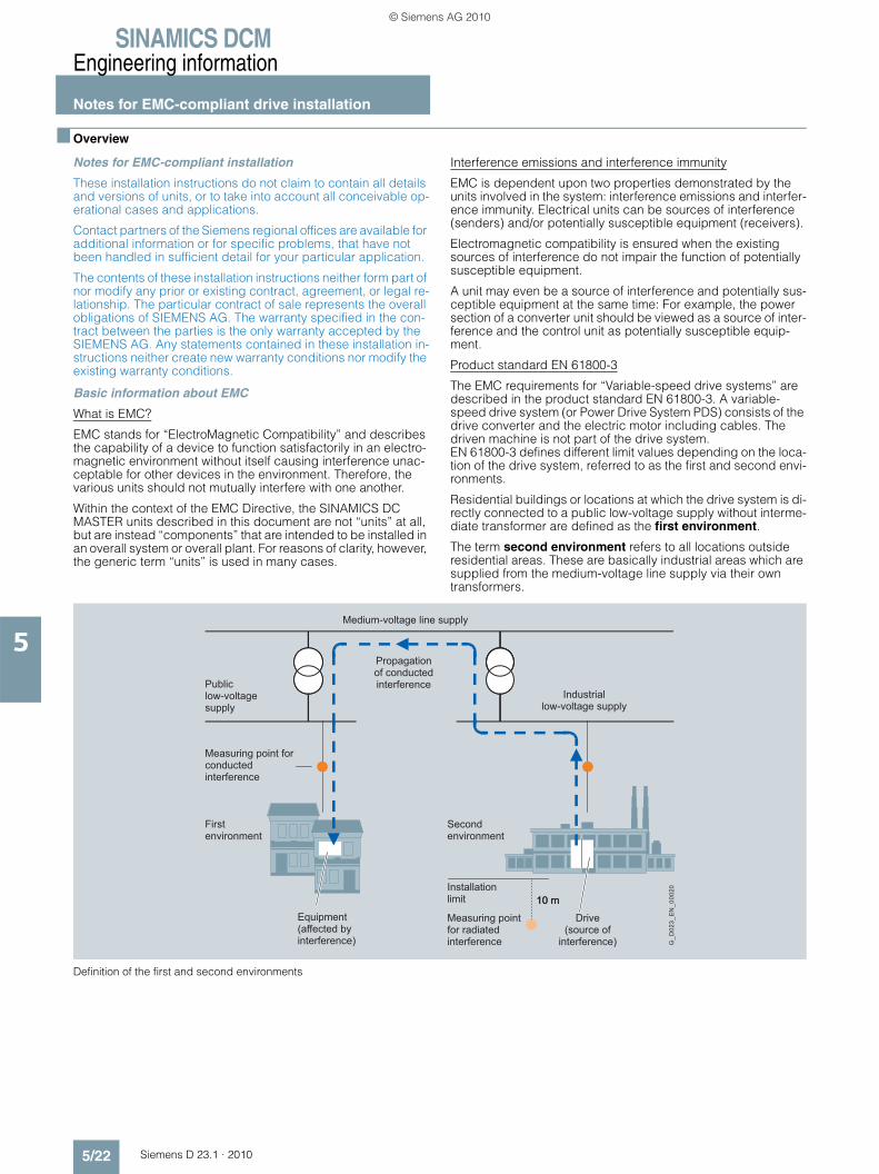
SINAMICS DCMEngineering information
Notes for EMC-compliant drive installation
5/22 Siemens D 23.1 · 2010
5
■ Overview
Notes for EMC-compliant installation
These installation instructions do not claim to contain all details and versions of units, or to take into account all conceivable op-erational cases and applications.
Contact partners of the Siemens regional offices are available for additional information or for specific problems, that have not been handled in sufficient detail for your particular application.
The contents of these installation instructions neither form part of nor modify any prior or existing contract, agreement, or legal re-lationship. The particular contract of sale represents the overall obligations of SIEMENS AG. The warranty specified in the con-tract between the parties is the only warranty accepted by the SIEMENS AG. Any statements contained in these installation in-structions neither create new warranty conditions nor modify the existing warranty conditions.
Basic information about EMC
What is EMC?
EMC stands for “ElectroMagnetic Compatibility” and describes the capability of a device to function satisfactorily in an electro-magnetic environment without itself causing interference unac-ceptable for other devices in the environment. Therefore, the various units should not mutually interfere with one another.
Within the context of the EMC Directive, the SINAMICS DC MASTER units described in this document are not “units” at all, but are instead “components” that are intended to be installed in an overall system or overall plant. For reasons of clarity, however, the generic term “units” is used in many cases.
Interference emissions and interference immunity
EMC is dependent upon two properties demonstrated by the units involved in the system: interference emissions and interfer-ence immunity. Electrical units can be sources of interference (senders) and/or potentially susceptible equipment (receivers).
Electromagnetic compatibility is ensured when the existing sources of interference do not impair the function of potentially susceptible equipment.
A unit may even be a source of interference and potentially sus-ceptible equipment at the same time: For example, the power section of a converter unit should be viewed as a source of inter-ference and the control unit as potentially susceptible equip-ment.
Product standard EN 61800-3
The EMC requirements for “Variable-speed drive systems” are described in the product standard EN 61800-3. A variable-speed drive system (or Power Drive System PDS) consists of the drive converter and the electric motor including cables. The driven machine is not part of the drive system. EN 61800-3 defines different limit values depending on the loca-tion of the drive system, referred to as the first and second envi-ronments.
Residential buildings or locations at which the drive system is di-rectly connected to a public low-voltage supply without interme-diate transformer are defined as the first environment.
The term second environment refers to all locations outside residential areas. These are basically industrial areas which are supplied from the medium-voltage line supply via their own transformers.
Definition of the first and second environments
10 m
G_D
023_
EN
_000
20
Drive(source of
interference)
Measuring point for radiated interference
Equipment(affected byinterference)
Secondenvironment
Firstenvironment
Measuring point forconducted interference
Industriallow-voltage supply
Publiclow-voltage supply
Propagationof conducted interference
Medium-voltage line supply
Installationlimit 10 m
© Siemens AG 2010

SINAMICS DCMEngineering information
Notes for EMC-compliant drive installation
5/23Siemens D 23.1 · 2010
5
■ Overview (continued)
Four different categories are defined in EN 61800-3 Ed.2 de-pending on the location and the power of the drive:
Category C1: Drive systems for rated voltages < 1 000 V for unlimited use in the first environment.
Category C2: Stationary drive systems for rated voltages < 1 000 V for use in the second environment. Use in the first environment is possible if the drive system is marketed and installed by qualified personnel. The warning information and installation instructions supplied by the manufacturer must be observed.
Category C3: Drive systems for rated voltages < 1 000 V for exclusive use in the second environment.
Category C4: Drive systems for rated voltages ≥ 1 000 V or for rated currents ≥ 400 A for use in complex systems in the second environment.
The following diagram shows how the four categories are as-signed to the first and second environments:
Definition of categories C1 to C4
SINAMICS DC MASTER units are nearly always used in the second environment (Categories C3 and C4).
Radio interference suppression filters and commutating reactors are required whenever they are to be used in Category C2.
SINAMICS DC MASTER units conform to the interference immu-nity requirements defined in EN 61800-3 for the second environ-ment, and thus also to the lower requirements in the first environ-ment.
Standard EN 55011
Some situations require compliance with standard EN 55011. This defines limit values for interference emissions in industrial and residential environments. The values that are measured are conducted interference at the line supply connection as interfer-ence voltage, and electromagnetically radiated interference as radio interference, under standardized conditions.
The standard defines limit values “A1” and “B1” which, for inter-ference voltage, apply to the 150 kHz – 30 MHz range and, for radio interference, the 30 MHz – 2 GHz range. Since SINAMICS DC MASTER converter units are used in industrial applications, they are subject to the limit value “A1”. In order to achieve limit value “A1”, the SINAMICS DC MASTER units must be provided with external radio interference suppression filters and commu-tating reactors.
SINAMICS DC MASTER, industrial applications
Industrial applications demand that units demonstrate an ex-tremely high level of interference immunity, but by contrast place very low requirements on them in terms of interference emission levels.
SINAMICS DC MASTER converter units are components of an electrical drive, such as contactors and switches. Qualified per-sonnel must integrate them into a drive system which, as an ab-solute minimum, consists of the converter unit, motor cables, and motor. Commutating reactors and fuses are also required in
most cases. Therefore, whether or not a limit value is adhered to is determined by the components being installed correctly. Lim-iting interference emission levels in line with limit value “A1” re-quires not only the converter unit itself, but also the radio inter-ference suppression filter assigned to it and the commutating reactor, at the very least. Without a radio interference suppres-sion filter, the interference emission level of SINAMICS DC MASTER converter units exceeds limit value “A1” of EN 55011.
If the drive forms part of a plant or system, it does not initially need to fulfill any interference emission requirements. However, EMC legislation does stipulate that the plant or system as a whole must be electromagnetically compatible with its environ-ment.
If all the control components in the plant or system (such as PLCs) demonstrate a level of interference immunity that is suit-able for industrial applications, then it is not necessary for every drive to adhere to limit value “A1”.
Non-grounded line supplies
Non-grounded line supplies (IT line supplies) are used in some branches of industry in order to increase the availability of the plant. In the event of a ground fault, no fault current flows and the plant can continue with production. However, in conjunction with radio interference suppression filters, in the case of a fault, a fault current flows, which can cause the drives to shut down or possibly even destroy the radio interference suppression filter. This is the reason that the product standard does not define any limit values for these types of line supplies. From an economics perspective, any necessary EMC conformance measures should be taken on the grounded primary side of the supply transformer.
EMC planning
If two units are not electromagnetically compatible, you can re-duce the interference emission level of the source of interference or increase the interference immunity of the potentially suscepti-ble equipment.
Sources of interference are generally power electronics units with high power consumption. Reducing their interference emis-sion levels requires complex filters. Potentially susceptible equipment usually refers to controlgear and sensors, including their evaluation circuit. Lower costs are involved with increasing the interference immunity of units with lower power ratings. This means, that from an economics perspective, increasing the in-terference immunity is generally a more favorable option for in-dustrial applications than reducing the interference emission level. For example, to maintain limit value class A1 of EN 55011, the radio interference voltage at the line supply connection point between 150 and 500 kHz can be a maximum of 79 dB (μV) and between 500 kHz and 30 MHz, a maximum of 73 dB (μV) (9 or 4.5 mV).
In industrial applications, EMC between units should be based on a carefully-balanced combination of the interference emis-sion and interference immunity levels.
The most cost-effective measure that can be put in place to achieve EMC conformance is to physically separate sources of interference and potentially susceptible equipment – provided that you have taken this option into account during the planning stage of your machine/plant. In the first instance, it is necessary to determine whether each unit used is a potential source of in-terference or potentially susceptible equipment. Within this con-text, converter units and contactors, for example, can be counted as sources of interference. While examples of poten-tially susceptible equipment include PLCs, encoders and sen-sors.
The components in the control cabinet (sources of interference and potentially susceptible equipment) must be physically sep-arated, by means of partition plates if necessary, or by installing them in metal enclosures.
C1
C2
C3
C4
First environment
Second environment
G_D213_EN_00009
© Siemens AG 2010
SINAMICS DCMEngineering information
Notes for EMC-compliant drive installation
5/24 Siemens D 23.1 · 2010
5
■ Overview (continued)
EMC-compliant drive installation (installation instructions)
General information
Not only are drives operated in a wide variety of environments, but the electrical components used (controls and switched mode power supplies, and so on) can also differ widely with re-spect to interference immunity and interference emission levels, meaning that all installation guidelines of any kind can offer is a practical compromise. This is the reason that it is possible to de-viate from the EMC rules on a case-for-case basis provided that individual measures are tested.
In order to ensure electromagnetic compatibility (EMC) in your control cabinets in rugged electrical environments and adhere to the standards required by the relevant legislating body, the EMC rules listed below should be followed during the construction and design stages.
Rules 1 to 10 are generally valid. Rules 11 to 15 must be followed in order to fulfill interference emission standards.
Rules for EMC-compliant installation
Rule 1 All metal parts of the control cabinet are connected with one an-other through a large surface area with a good electrical con-nection (not paint on paint!). If required, contact or serrated washers should be used. The cabinet door must be connected to the cabinet using the shortest possible grounding straps (at the top, center, and bottom).
Rule 2 Contactors, relays, solenoid valves, electromechanical operat-ing hours counters, etc., in the cabinet and – where applicable – in neighboring cabinets – must be provided with quenching combination, e.g. RC elements, varistors, and diodes. The pro-tective circuit must be directly connected to the particular coil.
Rule 3 Signal cables 1) if at all possible, should only be routed at just one level in the cabinet.
Rule 4 Unshielded cables in the same circuit (outgoing/incoming con-ductors) must be twisted wherever possible, or the area between them minimized, to prevent the unnecessary formation of frame antennae.
Rule 5 Connect spare wires at both ends to the cabinet ground (ground 2)). This achieves an additional shielding effect.
Rule 6 Avoid unnecessary cable lengths. This keeps coupling capaci-tances and inductances low.
Rule 7 Crosstalk is generally reduced, if cables are routed close to the control cabinet ground. Therefore, do not route cables freely around the cabinet, but route them as close as possible to the cabinet enclosure or to the mounting plates. This also applies to spare cables.
Rule 8 Signal and power cables must be physically separated (to pre-vent coupling paths!). A minimum distance of 20 cm must be ob-served.
If it is not possible to physically separate the encoder and motor cables, the encoder cable must be decoupled either using a partition or by routing it in a metal conduit. The partition or metal conduit must be grounded at several points.
Rule 9 Ground the shields of digital signal cables at both ends (source and destination), ensuring maximum contact area and good conductivity. In the event of poor equipotential bonding between the shield connections, run an additional equipotential bonding conductor with a cross-section of at least 10 mm2 parallel to the shield for the purpose of reducing the shield current. Generally speaking, the shields may also be connected to the cabinet en-closure (ground) at several points. The shields can be con-nected several times even outside the control cabinet.
Foil-type shields should be avoided, as they are at least 5 times less effective than braided shields.
Rule 10 Shields for analog signal cables may be connected to ground at both ends if the equipotential bonding is good (this must be done through a large surface area with good conductivity!). It can be assumed that equipotential bonding is good if all of the metal parts are interconnected with one another through a good electrical connection and the electronics components are sup-plied from a single source.
Connecting shields at one end prevents low-frequency, capaci-tive interference from being coupled in (e.g. 50 Hz hum). In this case, the shield should be connected in the control cabinet; whereby the shield can also be connected using a separate wire.
Rule 11 Ensure that the radio interference suppression filter is located close to the suspected source of interference. The filter must be attached to the cabinet enclosure, mounting plate, etc., through a large surface area. Incoming and outgoing cables must be physically separated.
Rule 12 Radio interference suppression filters must be used in order to conform to limit value class A1. Additional loads must be con-nected upstream of the filter (line side).
The control used and the manner in which the rest of the control cabinet is wired will determine whether an additional line filter needs to be installed.
Rule 13 A commutating reactor must be included in the field circuit for controlled field power supplies.
Rule 14 A commutating reactor must be included in the armature circuit of the converter.
Rule 15 The motor cables do not have to be shielded. There must be a clearance of at least 20 cm between the line supply feeder cable and the motor cables (field, armature). If necessary, a separat-ing metal partition should be used.
The cabinet design shown in the following diagram is intended to help the user become familiar with EMC-critical parts. This ex-ample does not claim to show all possible cabinet components or design options.
Additional diagrams show details that are not immediately clear in the overview diagram and which may also have an effect on the resistance to interference/interference emission levels of the cabinet as well as different shield connection techniques.
1) Signal cables are defined as: Digital signal cable: Cables for pulse encoders, serial interfaces, e.g. PROFIBUS-DP or analog signal cable, e.g. ± 10 V setpoint cable.
2) Generally speaking, “ground” refers to all metallic conductive parts that can be connected to a protective conductor, such as the cabinet enclo-sure, motor enclosure, or foundation ground etc..
© Siemens AG 2010
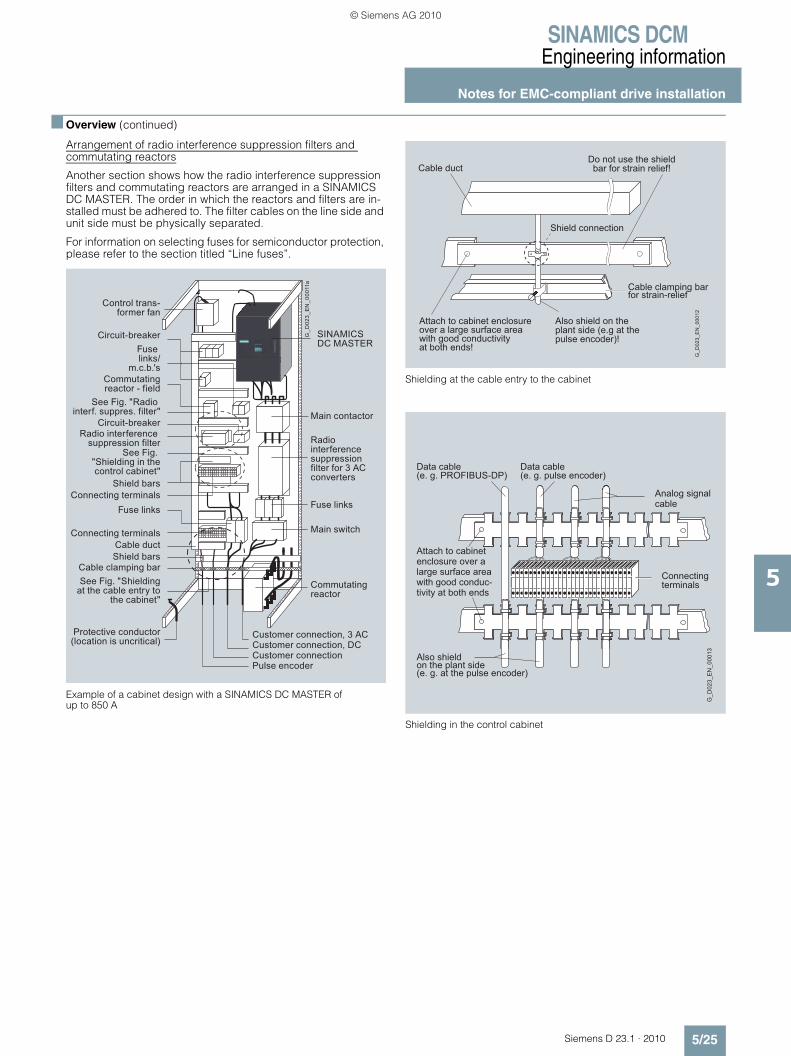
SINAMICS DCMEngineering information
Notes for EMC-compliant drive installation
5/25Siemens D 23.1 · 2010
5
■ Overview (continued)
Arrangement of radio interference suppression filters and commutating reactors
Another section shows how the radio interference suppression filters and commutating reactors are arranged in a SINAMICS DC MASTER. The order in which the reactors and filters are in-stalled must be adhered to. The filter cables on the line side and unit side must be physically separated.
For information on selecting fuses for semiconductor protection, please refer to the section titled “Line fuses”.
Example of a cabinet design with a SINAMICS DC MASTER of up to 850 A
Shielding at the cable entry to the cabinet
Shielding in the control cabinet
Customer connection, 3 ACCustomer connection, DCCustomer connectionPulse encoder
Control trans-former fan
Circuit-breakerFuse links/
m.c.b.'sCommutating reactor - field
Circuit-breaker
See Fig. "Radio interf. suppres. filter"
See Fig. "Shielding in the control cabinet"
Radio interference suppression filter
Shield barsConnecting terminals
Fuse links
Connecting terminalsCable duct
Protective conductor (location is uncritical)
Commutatingreactor
Main switch
Fuse links
Radio interference suppression filter for 3 AC converters
Main contactor
SINAMICS DC MASTER
Cable clamping barSee Fig. "Shielding
at the cable entry to the cabinet"
Shield bars
G_D
023_
EN
_000
11a
G_D
023_
EN
_000
12
Attach to cabinet enclosureover a large surface areawith good conductivityat both ends!
Do not use the shieldbar for strain relief!
Cable clamping bar for strain-relief
Cable duct
Also shield on the plant side (e.g at thepulse encoder)!
Shield connection
Analog signalcable
Data cable(e. g. pulse encoder)
Data cable(e. g. PROFIBUS-DP)
Connecting terminals
Attach to cabinetenclosure over alarge surface areawith good conduc-tivity at both ends
Also shield on the plant side(e. g. at the pulse encoder)
G_D
023_
EN
_000
13
© Siemens AG 2010

SINAMICS DCMEngineering information
Notes for EMC-compliant drive installation
5/26 Siemens D 23.1 · 2010
5
■ Overview (continued)
Radio interference suppression filter for theSINAMICS DC MASTER field power section
Radio interference suppression filter
Shield connection
Shield connection
$ Connecting terminal on a copper bar, max. cable diameter 15 mm
% Bar-mounting terminal on a copper bar, max. cable diameter 10 mm
& Metal tube or cable tie on a bare-metal comb-type/toothed bar
( Clamp with metal backing plate on a cable support rail
L1L2
L3
NETZ/LINE LAST/LOAD
L1L2
L3
Separate unfiltered andfiltered cables
Separate unfiltered and filtered cables
Connect the line filter to the cabinet enclosure through large surface area
Linecon-nection
Connect protective conductor
Power section connection, field circuit
G_D023_EN_00018
G_D
023_
XX
_000
19
1 2 3 4
© Siemens AG 2010

SINAMICS DCMEngineering information
Notes for EMC-compliant drive installation
5/27Siemens D 23.1 · 2010
5
■ Overview (continued)
Arrangement of the components for converter units
Arrangement of reactors and radio interference suppression filters
(1) The commutating reactor in the field circuit is dimensioned for the rated motor field current.
(2) The commutating reactor in the armature circuit is dimen-sioned for the rated motor armature current. The line current is 0.82 times the DC current.
(3) The radio interference suppression filter for the armature circuit is dimensioned for the rated motor armature current.The line current is 0.82 times the DC current.
(4) The radio interference suppression filter for the field circuit is dimensioned for the rated motor field current.
(5) Radio interference suppression filters are not required for the electronics power supply alone. Current consumption at 400 V 1 A, at 230 V 2 A.
(6) If the power supply voltages for the armature circuit, field circuit and electronics power supply are the same, then the voltage for the field and electronics power supply can also be taken after the radio interference suppression filter for the armature circuit.
230 V
NC
5U1 5N1 5U1 5W1 3U1
Field
SINAMICS DC MASTER
Armature
3W1 1U1 1V1 1W1
3C 3D
M
1C1 1D1
5W1
400 V400 V Line supply voltage
Power supply230 V AC or 400 V AC
(1)
(5) (6) (5) (6) (4) (6) (3) (6)
(2)
G_D
023_
EN
_000
04a
5N1
© Siemens AG 2010

SINAMICS DCMEngineering information
Harmonics
5/28 Siemens D 23.1 · 2010
5
■ Overview
Line-side harmonics produced by converter units in a fully-controlled three-phase bridge circuit B6C and (B6)A(B6)C
The majority of converter units for medium-power applications have a fully-controlled three-phase bridge circuit. Below is an example of the harmonics that can be found in a typical system configuration for two firing angles (α = 20° and α = 60°).
The values have been taken from a previous publication, “Oberschwingungen im netzseitigen Strom sechspulsiger netzgeführter Stromrichter (Harmonics in the Line-Side Current of Six-Pulse, Line-Commutated Converters)” by H. Arremann and G. Möltgen, Siemens Research and Development Division, Volume 7 (1978) No. 2, © Springer-Verlag 1978.
In addition, the formulas are specified which, depending on the actual operating data in use, line supply voltage (no-load volt-age VV0), line frequency fN and DC current Id, can be used to calculate the short-circuit power SK and armature inductance La for the motor to which the specified harmonics spectrum ap-plies.
If the actual line short-circuit power and/or actual armature in-ductance deviate from the values calculated in this way, then they will need to be calculated on a case-by-case basis.
The harmonics spectrum shown below is obtained if the values for the short-circuit power SK at the point where the unit is con-nected and the armature inductance La of the motor, calculated using the following formulas, match the actual values of the plant or system. If the values do not match, the harmonics will have to be separately calculated.
The fundamental component of current I1 as a reference variable is calculated using the following formula:
I1 = g × 0.817 × IdId DC current of the operating point being investigated g Basic fundamental content
The harmonics currents calculated according to the table only apply for:
a) Short-circuit power SK at the point where the converter unit is connected
SK = VV02/XN (VA)
where
XN = XK - XD = 0.03536 × VV0/Id - 2π × fN × LD (Ω)
VV0 No-load voltage at the point where the converter unit is connected in V
Id DC current of the operating point being investigated in A
fN Line frequency in Hz
LD Inductance of the commutating reactor being used in H
b) Armature inductance La
La = 0.0488 × VV0/(fN × Id) (H)
If the actual values for the short-circuit power SK and/or armature inductance La deviate from the values calculated using the for-mulas above, a separate calculation will need to be made.
Example:
Let us assume a drive with the following data:
VV0 = 400 V
Id = 150 A
fN = 50 Hz
LD = 0.169 mH (4EU2421-7AA10) with ILN = 125 A
where
XN = 0.03536 × 400/150 - 2 π × 0.169 × 10–3 = 0.0412 Ω
The following short-circuit power of the line supply required at the point where the converter is connected:
SK = 4002/0.0412 = 3.88 MVA
and the following armature inductance of the motor required:
La = 0.0488 × 400/(50 × 150) = 2.0 mH
The harmonics currents Iν (with I1 = g × 0.817 × Id for firing angles α = 20° and α = 60°) that can be taken from the tables, only apply for the values SK and La that have been calculated in this way. If the actual values deviate from these, a separate cal-culation will have to be made.
For the purpose of dimensioning filters and compensation equipment with reactors, it is only possible to draw on the infor-mation provided by the harmonic values calculated in this way if the calculated values SK and La match the actual drive values. In all other cases, a separate calculation will have to be made (this particularly applies when using compensated motors as they have very low armature inductance levels).
ν Iν/I1at α = 20°fundamental factorg = 0.962
at α = 60°fundamental factorg = 0.953
5 0.235 0.283
7 0.100 0.050
11 0.083 0.089
13 0.056 0.038
17 0.046 0.050
19 0.035 0.029
23 0.028 0.034
25 0.024 0.023
29 0.018 0.026
31 0.016 0.019
35 0.011 0.020
37 0.010 0.016
41 0.006 0.016
43 0.006 0.013
47 0.003 0.013
49 0.003 0.011
© Siemens AG 2010

Siemens D 23.1 · 2010
66/2 SIZER LD web engineering tool6/2 Overview
6/3 STARTER commissioning tool6/3 Overview6/3 Integration6/3 Selection and ordering data6/4 Accessories
6/5 Drive Control Chart (DCC)6/5 Overview6/5 Selection and ordering data
6/6 Drive ES engineering software6/6 Overview6/6 Application6/6 Design6/7 Selection and ordering data6/8 Options
Tools and engineering
© Siemens AG 2010

SINAMICS DCMTools and engineering
SIZER LD web engineering tool
6/2 Siemens D 23.1 · 2010
6
■ Overview
SIZER LD web is used when engineering SINAMICS DC MASTER. It provides supply when selecting and dimensioning the converter, associated options and accessories required for the particular application. SIZER LD web is implemented as web-based application (Internet): http://www.siemens.com/sizer-ld.
SIZER LD web supports all of the engineering stages of a converter in just one workflow:• Enter the motor data, converter data and AC line supply data• Select the SINAMICS DC MASTER options• Compile the required documentation and accessories
The SIZER LD web user interface is in German and English.
The engineered drive is saved in a project. From the general idea and the structure, the “Projects” and “Project items” set up in the system correspond to quotations. These are all saved on one server and can be recalled at any time.
Results of the engineering process include:• Data sheet with the technical data of the engineered converter
and where relevant, the accessories• Dimension drawing of the converter
The results and dimension drawings can be saved or exported to technical quotation documentation.
SIZER LD web requires the following preconditions for its use: • Internet connection• Login for SSO (Single-Sign-On) through
http://www.siemens.com/sizer-ld• SIZER LD web Version 1 has been designed for Internet
Explorer 6 or higher. Mozilla Firefox, Safari (Mac OS) and Opera are also supported from Version 2 and higher.
However, in the future, SINAMICS DC MASTER will not only be able to be engineered in SIZER LD web. It is also possible to engineer the unit in the Industry Mall (https://mall.automation.siemens.com/) directly via the configu-rator list. Almost the whole of the Industry product catalog can be called-up in the Industry Mall – including Configurators for a wide range of products – without having to enter a Login. After logging on to the Mall, users can view the prices and add the products that have been selected into the Mall shopping cart and then enter an order.
© Siemens AG 2010

SINAMICS DCMTools and engineering
STARTER commissioning tool
6/3Siemens D 23.1 · 2010
6
■ Overview
The user-friendly STARTER commissioning tool can be used for:• Commissioning• Optimization and• Diagnostics
This software can either be operated as a stand-alone PC appli-cation or can be integrated into the SCOUT engineering system (with SIMOTION) or STEP 7 (with Drive ES Basic). The basic functions and handling are the same in both cases.
In addition to the SINAMICS DC MASTER, the current version of STARTER also supports all of the SINAMICS AC drives – includ-ing MICROMASTER 4 and the frequency converters for the SIMATIC ET 200S FC distributed I/O.
SINAMICS DC MASTER is supported from STARTER 4.1.5; it is not possible to use older STARTER versions.
The project wizards can be used to create the drives within the structure of the project tree.
Entry level personnel are interactivelly supported in a solution-oriented way.
First commissioning is guided by a wizard which makes all of the basic settings in the drive. Therefore, getting a motor up and run-ning is merely a question of setting a few of the drive parameters as part of the drive configuration process.
Examples of individual settings that can be made include:• Terminals • Bus interface• BICO interconnections• Diagnostics
Experts can quickly access all of the parameters via the Expert List and do not have to navigate through dialogs.
In addition, the following functions are available for optimization purposes:• Trace (depending on drive)
Diagnostic functions provide information about:• Control/status words• Parameter status• Operating conditions• Communication states
Performance features • Easy to use: Only a small number of settings need to be made
to successfully commission the drive for the first time: Motor rotates
• Solution-based user navigation simplifies commissioning• The built-in trace function provides optimum support during
commissioning, optimization and troubleshooting
Minimum hardware and software requirements
PG or PC with Pentium III 1 GHz
512 MB RAM (1 GB RAM recommended)
Screen resolution 1 024 × 768 pixels, 16 bit color depth
Free hard disk memory: 2 GB
Windows 2000 SP4, Windows 2003 Server SP1, SP2
Windows XP Professional SP2 or SP3
Windows Vista Business SP1, Windows Vista Ultimate SP1
Microsoft Internet Explorer 6.0
■ Integration
Communication between the Control Unit of the drive and the programming device (PG) or PC can be established via a serial interface, via PROFIBUS or PROFINET.
The following accessories are available for the particular drive system:
SINAMICS DC MASTER
A PROFIBUS communication module and a connecting cable are required to establish communication between a PG/PC and a CUD.
For example, the PROFIBUS communication module CP 5512 (PCMCIA type 2 card + adapter with 9-pin SUB-D socket for connection to PROFIBUS. For MS Windows 2000/XP Professional and PCMCIA 32)Order No.: 6GK1551-2AA00
and a connecting cable between CP 5512 and PROFIBUSOrder No.: 6ES7901-4BD00-0XA0
■ Selection and ordering data
STARTER version 4.1 with Service Pack 5, Hotfix 1 is required for SINAMICS DC MASTER.
If new converter units are launched into the market or if the func-tionality of a converter is extended by new software, then it is not necessary to install new STARTER software. STARTER can be updated by installing an SSP (SINAMICS Support Package). The actual STARTER version as well as updates can be downloaded from the Internet under http://support.automation.siemens.com/WW/view/en/10804985/133100 and are provided in the product DVD supplied with each unit.
Order No.
STARTER commissioning tool for SINAMICS and MICROMASTEREnglish/French/German/Italian/Spanish
6SL3072-0AA00-0AG0
© Siemens AG 2010
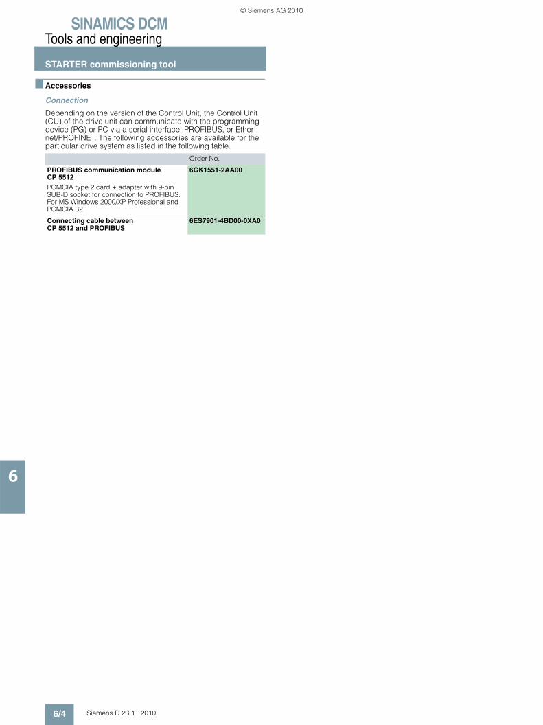
SINAMICS DCMTools and engineering
STARTER commissioning tool
6/4 Siemens D 23.1 · 2010
6
■ Accessories
Connection
Depending on the version of the Control Unit, the Control Unit (CU) of the drive unit can communicate with the programming device (PG) or PC via a serial interface, PROFIBUS, or Ether-net/PROFINET. The following accessories are available for the particular drive system as listed in the following table.
Order No.
PROFIBUS communication module CP 5512PCMCIA type 2 card + adapter with 9-pin SUB-D socket for connection to PROFIBUS. For MS Windows 2000/XP Professional and PCMCIA 32
6GK1551-2AA00
Connecting cable between CP 5512 and PROFIBUS
6ES7901-4BD00-0XA0
© Siemens AG 2010

SINAMICS DCMTools and engineering
Drive Control Chart (DCC)
6/5Siemens D 23.1 · 2010
6
■ Overview
Graphically configuring and expanding the device functionality using the freely available closed-loop control, arithmetic, and logic blocks
Drive Control Chart (DCC) extends the possibility of very simply configuring technological functions – both for the SIMOTION motion control system as well as for the SINAMICS DC MASTER drive system. For users, this opens up a new dimension regard-ing the adaptability of the systems mentioned to the specific functions of their machines. DCC has no restrictions with regard to the number of usable functions; this is only limited by the per-formance capability of the target platform.
The user-friendly DCC editor enables easy graphics-based con-figuration, allows control loop structures to be clearly repre-sented and provides a high degree of reusability of diagrams that have already been created.
The open-loop and closed-loop control functions are defined by using multi-instance-capable blocks (Drive Control Blocks (DCBs)) from a pre-defined library (DCB library) that are se-lected and graphically linked with one another by dragging and dropping. Test and diagnostic functions allow the program be-havior to be verified and in the case of a fault, the cause identi-fied.
The block library encompasses a large selection of closed-loop, arithmetic and logic blocks, as well as comprehensive open-loop and closed-loop control functions.
For logically combining, evaluating and acquiring binary sig-nals, all commonly used logic functions are available for selec-tion (AND, XOR, on/off delay, RS flipflop, counter, etc.). A wide range of arithmetic functions, such as absolute value generation, dividers and minimum/maximum evaluation are available to monitor and evaluate numerical quantities. In addition to the closed-loop drive control, axial winder functions, closed-loop PI controller, ramp function generator or wobble generator can be configured simply and easily.
Closed-loop control structures can be programmed with almost no restrictions in conjunction with the SIMOTION motion control system. These can then be combined with other program sec-tions to form an overall program.
Further, Drive Control Chart for SINAMICS DC MASTER provides a user-friendly basis to handle drive-related open-loop and closed-loop control tasks directly in the converter. This further extends the possibility of adapting SINAMICS to the particular application. Local data processing in the drive supports the implementation of modular machine concepts and results in an increase in the overall machine performance.
Minimum hardware and software requirements
See the SCOUT or STARTER engineering software, since DCC is installed in addition to this.
Note: In order to download the DCB library into the drive, it is necessary to use a memory card for the first time (option S01 or option S02 when using a Standard CUD right (option G10) or an Advanced CUD right (option G11)).
■ Selection and ordering data
DCC comprises the graphic configuring tool (DCC Editor) and the block library (DCB Library).
DCC is installed in addition to the SCOUT or STARTER engineer-ing software.
The necessary engineering license for each PC (floating) for DCC is acquired at the same time the order is placed; additional run time licenses are not required.
DCC can be ordered in two versions: The version for SIMOTION and SINAMICS applications, or the version for SINAMICS appli-cations only.
Order No.
DCC-SIMOTION/-SINAMICS V2.0 SP1for SCOUT/STARTER V4.1 SP1(single-user engineering license, with DCC data carrier)DCC editor + DCB libraries for use on SIMOTION V4.1 SP1 and SINAMICS S120 V2.5 SP1German/English/French/Italian (SIMOTION)German/English/French/Italian/Spanish (SINAMICS)
6AU1810-1JA20-1XA0
DCC-SINAMICS V2.0 SP1for STARTER V4.1 SP1(single-user engineering license, with DCC data carrier)DCC editor + DCB library for use on SINAMICS S120 V2.5 SP1German/English/French/Italian/Spanish
6AU1810-1HA20-1XA0
© Siemens AG 2010
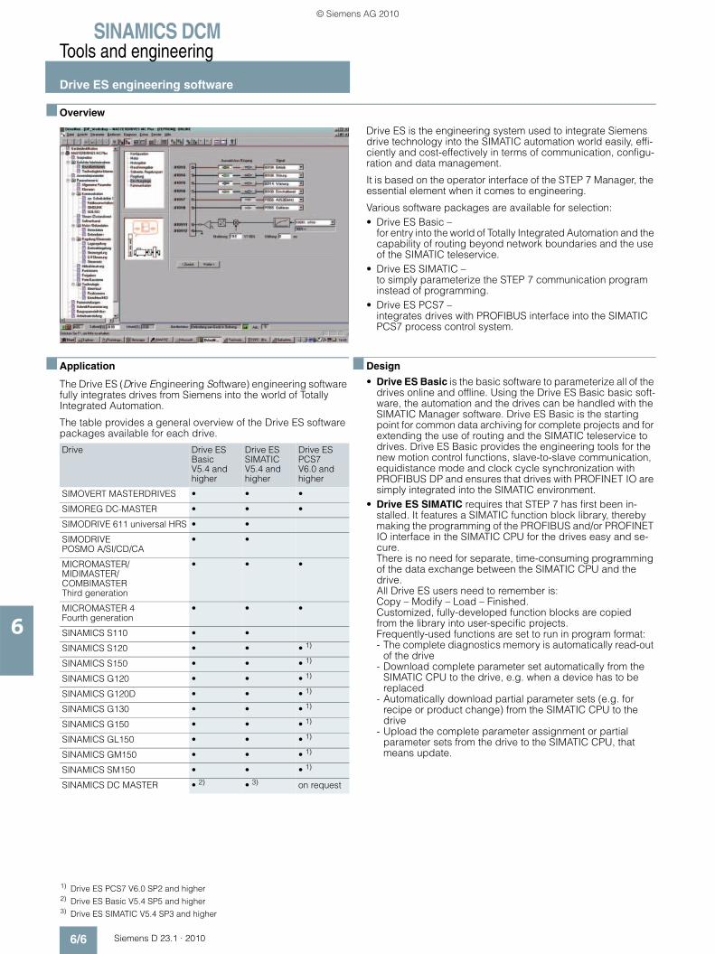
SINAMICS DCMTools and engineering
Drive ES engineering software
6/6 Siemens D 23.1 · 2010
6
■ Overview
Drive ES is the engineering system used to integrate Siemens drive technology into the SIMATIC automation world easily, effi-ciently and cost-effectively in terms of communication, configu-ration and data management.
It is based on the operator interface of the STEP 7 Manager, the essential element when it comes to engineering.
Various software packages are available for selection:• Drive ES Basic –
for entry into the world of Totally Integrated Automation and the capability of routing beyond network boundaries and the use of the SIMATIC teleservice.
• Drive ES SIMATIC – to simply parameterize the STEP 7 communication program instead of programming.
• Drive ES PCS7 – integrates drives with PROFIBUS interface into the SIMATIC PCS7 process control system.
■ Application
The Drive ES (Drive Engineering Software) engineering software fully integrates drives from Siemens into the world of Totally Integrated Automation.
The table provides a general overview of the Drive ES software packages available for each drive.
■ Design
• Drive ES Basic is the basic software to parameterize all of the drives online and offline. Using the Drive ES Basic basic soft-ware, the automation and the drives can be handled with the SIMATIC Manager software. Drive ES Basic is the starting point for common data archiving for complete projects and for extending the use of routing and the SIMATIC teleservice to drives. Drive ES Basic provides the engineering tools for the new motion control functions, slave-to-slave communication, equidistance mode and clock cycle synchronization with PROFIBUS DP and ensures that drives with PROFINET IO are simply integrated into the SIMATIC environment.
• Drive ES SIMATIC requires that STEP 7 has first been in-stalled. It features a SIMATIC function block library, thereby making the programming of the PROFIBUS and/or PROFINET IO interface in the SIMATIC CPU for the drives easy and se-cure.There is no need for separate, time-consuming programming of the data exchange between the SIMATIC CPU and the drive.All Drive ES users need to remember is: Copy – Modify – Load – Finished. Customized, fully-developed function blocks are copied from the library into user-specific projects. Frequently-used functions are set to run in program format:- The complete diagnostics memory is automatically read-out
of the drive- Download complete parameter set automatically from the
SIMATIC CPU to the drive, e.g. when a device has to be replaced
- Automatically download partial parameter sets (e.g. for recipe or product change) from the SIMATIC CPU to the drive
- Upload the complete parameter assignment or partial parameter sets from the drive to the SIMATIC CPU, that means update.
Drive Drive ESBasicV5.4 and higher
Drive ESSIMATICV5.4 and higher
Drive ESPCS7V6.0 and higher
SIMOVERT MASTERDRIVES • • •
SIMOREG DC-MASTER • • •
SIMODRIVE 611 universal HRS • •
SIMODRIVE POSMO A/SI/CD/CA
• •
MICROMASTER/MIDIMASTER/COMBIMASTERThird generation
• • •
MICROMASTER 4Fourth generation
• • •
SINAMICS S110 • •
SINAMICS S120 • • • 1)
SINAMICS S150 • • • 1)
SINAMICS G120 • • • 1)
SINAMICS G120D • • • 1)
SINAMICS G130 • • • 1)
SINAMICS G150 • • • 1)
SINAMICS GL150 • • • 1)
SINAMICS GM150 • • • 1)
SINAMICS SM150 • • • 1)
SINAMICS DC MASTER • 2) • 3) on request
1) Drive ES PCS7 V6.0 SP2 and higher2) Drive ES Basic V5.4 SP5 and higher3) Drive ES SIMATIC V5.4 SP3 and higher
© Siemens AG 2010

SINAMICS DCMTools and engineering
Drive ES engineering software
6/7Siemens D 23.1 · 2010
6
■ Design (continued)
Detailed contents of the Drive ES SIMATIC package:- “PROFIBUS DP” communications software for S7-300
with CPUs with integrated DP interface (DRVDPS7, POSMO function block libraries), S7-400 with CPUs with integrated DP interface or with CP443-5 (DRVDPS7, POSMO function block libraries) and S7-300 with CP342-5 (DRVDPS7C func-tion block library)
- “USS protocol” communications software for S7-300 with integrated PtP interfaces or with CP 340/341 and S7-400 with CP 441 (DRVUSSS7 function block library)
- STEP 7 slave object manager for the easy configuration of drives as well as for non-cyclic PROFIBUS DP communica-tion with the drives; supports the conversion of DVA_S7 to Drive ES projects (V5.1 and higher)
- STEP 7 device object manager for convenient configura-tion of drives with PROFINET IO interfaces (V5.4 and higher)
- SETUP program for installing the software in the STEP 7 en-vironment
- “PROFINET IO” communications software for S7-300 with CPUs with integrated PN interface, S7-400 with CPUs with integrated PN interface or with CP (DRVDPS7 function block library, respectively). PROFINET IO and PROFIBUS DP use the same blocks from the DRVDPS7 library, i.e. the blocks are able to serve both buses with a common block (only for V5.4 and higher)
• Drive ES PCS7 requires that SIMATIC PCS7 (version 5.2 and higher) has first been installed. Drive ES PCS7 provides a function block library with function blocks for the drives and the corresponding faceplates for the operator station which enables the drives to be operated from the PCS7 process con-trol system. From version V6.1 and higher, drives will also be able to be represented in the PCS7 Maintenance Station.
Detailed contents of the Drive ES PCS7 package: - Block library for SIMATIC PCS7 Faceplates and control
blocks for SIMOVERT MASTERDRIVES VC and MC, as well as MICRO-/MIDIMASTER of the third and fourth generation and SIMOREG DC-MASTER and SINAMICS
- STEP 7 slave object manager for convenient configuration of drives and acyclic PROFIBUS DP communications with the drives
- SETUP program for installing the software in the PCS7 environment
■ Selection and ordering data
Order No.
Drive ES Basic V5.4 SPx 1)
• Configuration software for the integration of drives into Totally Integrated Automation
• Precondition: STEP 7 V5.3 and higher, SP 3• Supply as: DVD
English/French/German/Italian/Spanish with electronic documentation
Floating license, 1 user 6SW1700-5JA00-4AA0
Floating license, (copy license), 60 users 6SW1700-5JA00-4AA1
Update service for single-user license 6SW1700-0JA00-0AB2
Update service for copy license, 60 users 6SW1700-0JA00-1AB2
Upgrade from V5.x to V5.4 SPx 1) 6SW1700-5JA00-4AA4
Drive ES SIMATIC V5.4 SPx 1)
• Function block library for SIMATIC for the parameterization of communication with the drives
• Precondition: STEP 7, V5.3 and higher, SP 3• Supply as: CD-ROM
English/French/German/Italian/Spanish with electronic documentation
Single-user license incl. 1x runtime license 6SW1700-5JC00-4AA0
Runtime license (without data carrier) 6SW1700-5JC00-1AC0
Update service for single-user license 6SW1700-0JC00-0AB2
Upgrade from V5.x to V5.4 SPx 1) 6SW1700-5JC00-4AA4
Drive ES PCS7 V6.1 SPx 1)
• Block library for PCS7 for the integration of drives
• Precondition: PCS7, V6.1 and higher• Supply as: CD-ROM
English/French/German/Italian/Spanish with electronic documentation
Single-user license incl. 1x runtime license 6SW1700-6JD00-1AA0
Runtime license (without data carrier) 6SW1700-5JD00-1AC0
Update service for single-user license 6SW1700-0JD00-0AB2
Upgrade from V5.x to V6.1 SPx 1) 6SW1700-6JD00-1AA4
Drive ES PCS7 V7.0 SPx 1)
• Block library for PCS7 for the integration of drives
• Precondition: PCS7, V7.0 and higher• Supply as: CD-ROM
English/French/German/Italian/Spanish with electronic documentation
Single-user license, incl. 1x runtime license 6SW1700-7JD00-0AA0
Runtime license (without data carrier) 6SW1700-5JD00-1AC0
Update service for single-user license 6SW1700-0JD00-0AB2
Upgrade from V5.x to V7.0 SPx 1) 6SW1700-7JD00-0AA4
1) Orders are always automatically supplied with the latest SP.
© Siemens AG 2010

SINAMICS DCMTools and engineering
Drive ES engineering software
6/8 Siemens D 23.1 · 2010
6
■ Options
Drive ES software update service
A software update service can also be purchased for the Drive ES software. The user will automatically receive the latest soft-ware, service packs and full versions for one year after ordering.
The update service can only be ordered in addition to an existing (i.e. previously ordered) full version.• Period of update service: 1 year
The update service is automatically extended by 1 further year unless canceled up to 6 weeks prior to expiration.
Order No.
Drive ES Basic
Update service for single-user license 6SW1700-0JA00-0AB2
Update service for copy license 6SW1700-0JA00-1AB2
Drive ES SIMATIC
Update service for single-user license 6SW1700-0JC00-0AB2
Drive ES PCS7
Update service for single-user license 6SW1700-0JD00-0AB2
© Siemens AG 2010

Siemens D 23.1 · 2010
77/2 SINAMICS DCM demonstration case7/2 Overview7/2 Application7/2 Function7/2 Technical specifications7/2 Selection and ordering data
7/3 Training7/3 Overview7/3 • Faster and more applicable know-how:
Hands-on training from the manufacturer7/3 • SITRAIN highlights
7/4 Range of training courses7/4 Overview7/4 • Commissioning SINAMICS DCM
7/5 Service & Support – Services covering the entire life cycle
7/5 Online Support7/5 Technical Support7/5 Technical Consulting7/5 Engineering Support7/5 Field Service7/5 Spare Parts and Repairs7/5 Optimization and Upgrading7/6 Knowledge Base on DVD7/6 Automation Value Card
7/7 Documentation7/7 Overview7/7 Selection and ordering data
Services and documentation
© Siemens AG 2010

SINAMICS DCMServices and documentation
SINAMICS DCM demonstration case
7/2 Siemens D 23.1 · 2010
7
■ Overview
Demonstration case, opened
The SINAMICS DC MASTER demonstration model is installed ready to be connected-up in a rugged transport case and is immediately ready for operation. It comprises a DC converter 480 V 3 AC, DC 30 A, a 1 kW DC motor as well as numerous options and accessories. The case has two integrated transport wheels and a hinged handle.
Scope of delivery
The following main components are included in the SINAMICS DC MASTER demonstration case, including all of the required wiring, connection and signal cables:• DC converter 6RA8018-6FV62-0AA0-Z;
Z=G00+G10+G20+S01G00 = Advanced CUD leftG10 = Standard CUD rightG20 = Communication Board CBE20 leftS01 = Memory card left
• TM31 Terminal Module • TM15 Terminal Module • AOP30 Advanced Operator Panel • Radio interference suppression filter• Three-phase commutating reactor for the armature circuit• Single-phase commutating reactor for the field circuit• DC motor 1 kW, 1 750 rpm• Pulse encoder OG 60 DN 2040 CI• Analog tachometer GT 5.05 L/410, Vo = 10 V/1 000 rpm• Commissioning box for SINAMICS DC MASTER to control
analog and digital inputs and outputs
Free function blocks and Drive Control Chart can be used with-out any restrictions.
The demonstration case is also available without integrated DC motor to operate an externally mounted DC motor. (The rated converter data must be observed.)
■ Application
• Demonstrating DC drives to customers• Training Siemens employees and customers• Test configurations
An automation group using a SIMATIC demonstration case to-gether with one or several SINAMICS DC MASTER demonstra-tion cases can be implemented.
■ Function
Operation
The converter can be operated from:• the commissioning box, which is connected to the terminals of
the unit or the TM15 and TM31 • the AOP30 operator panel • the PROFIBUS interface• the PROFINET interface
A description is provided with the demonstration case. This clearly shows the principle operator panel design and the possible functions of the operator controls.
To use the STARTER commissioning tool users require a programming device or PC. The system requirements are described in section STARTER.
■ Technical specifications
■ Selection and ordering data
The demonstration case with integrated DC motor is also available for rental. Please contact your regional Siemens sales person.
SINAMICS DCM demonstration case
Line supply connection
Supply voltage 400 V 3 AC (+15 %/-20 %)
Rated frequency 45 … 65 Hz
Connecting cable with 16-A-CECON connector (5UR5076-3), length
approx. 4 m
Line connection fusing required 16 A
Dimensions and weights
• Width approx. 680 mm
• Height approx. 700 mm
• Depth approx. 430 mm
Weight with integrated DC motor approx. 70 kg
Weight without motor approx. 55 kg
SINAMICS DCM demonstration case
Description Order No.
With integrated DC motor 6RX1800-0SM00
Without motor 6RX1800-0SV00
© Siemens AG 2010
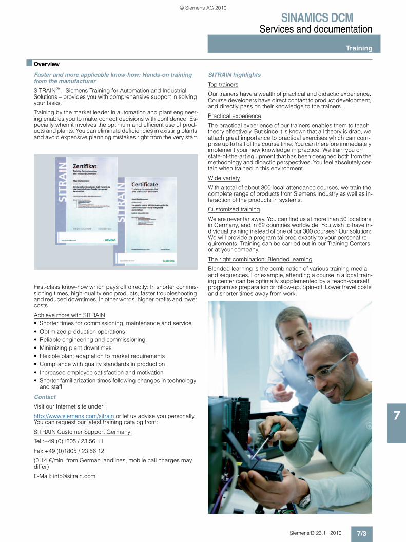
SINAMICS DCMServices and documentation
Training
7/3Siemens D 23.1 · 2010
7
■ Overview
Faster and more applicable know-how: Hands-on training from the manufacturer
SITRAIN® – Siemens Training for Automation and Industrial Solutions – provides you with comprehensive support in solving your tasks.
Training by the market leader in automation and plant engineer-ing enables you to make correct decisions with confidence. Es-pecially when it involves the optimum and efficient use of prod-ucts and plants. You can eliminate deficiencies in existing plants and avoid expensive planning mistakes right from the very start.
First-class know-how which pays off directly: In shorter commis-sioning times, high-quality end products, faster troubleshooting and reduced downtimes. In other words, higher profits and lower costs.
Achieve more with SITRAIN• Shorter times for commissioning, maintenance and service• Optimized production operations• Reliable engineering and commissioning• Minimizing plant downtimes• Flexible plant adaptation to market requirements• Compliance with quality standards in production• Increased employee satisfaction and motivation• Shorter familiarization times following changes in technology
and staff
Contact
Visit our Internet site under:
http://www.siemens.com/sitrain or let us advise you personally. You can request our latest training catalog from:
SITRAIN Customer Support Germany:
Tel.:+49 (0)1805 / 23 56 11
Fax:+49 (0)1805 / 23 56 12
(0.14 €/min. from German landlines, mobile call charges may differ)
E-Mail: [email protected]
SITRAIN highlights
Top trainers
Our trainers have a wealth of practical and didactic experience. Course developers have direct contact to product development, and directly pass on their knowledge to the trainers.
Practical experience
The practical experience of our trainers enables them to teach theory effectively. But since it is known that all theory is drab, we attach great importance to practical exercises which can com-prise up to half of the course time. You can therefore immediately implement your new knowledge in practice. We train you on state-of-the-art equipment that has been designed both from the methodology and didactic perspectives. You feel absolutely cer-tain when trained in this environment.
Wide variety
With a total of about 300 local attendance courses, we train the complete range of products from Siemens Industry as well as in-teraction of the products in systems.
Customized training
We are never far away. You can find us at more than 50 locations in Germany, and in 62 countries worldwide. You wish to have in-dividual training instead of one of our 300 courses? Our solution: We will provide a program tailored exactly to your personal re-quirements. Training can be carried out in our Training Centers or at your company.
The right combination: Blended learning
Blended learning is the combination of various training media and sequences. For example, attending a course in a local train-ing center can be optimally supplemented by a teach-yourself program as preparation or follow-up. Spin-off: Lower travel costs and shorter times away from work.
© Siemens AG 2010

SINAMICS DCMServices and documentation
Range of training courses
7/4 Siemens D 23.1 · 2010
7
■ Overview
Commissioning SINAMICS DCM
Description/learning objective
This training course explains how you adapt the parameter set-tings of the converter to the application and the DC motor. You expand your theoretical knowledge in the form of exercises car-ried out on special training equipment. After participating in the course, you know the functions of a converter and the interfaces. You are in a position to safely and quickly commission the unit. Through routine fault diagnostics and troubleshooting, you save time and optimize the availability of your plant or system.
Target group
Commissioning engineers, project engineers, service personnel
Preconditions
Basic knowledge of electrical engineering
Content• Design and function of the SINAMICS DC MASTER converter:
- Control module CUD- Power section- Field circuit- Interfaces- Circuit diagrams
• Commissioning and parameterizing using the BOP20 and AOP30 operator panels and the STARTER PC program
• Using the memory card: Structure and data backup• Procedure when commissioning, checking functions• Optimizing the closed-loop current and speed control, auto-
matic optimization• Function diagrams: Setpoint channel, inputs and outputs, free
function blocks• Information on Drive Control Chart DCC• Drive interface to PROFIBUS / PROFINET• Expanding the system using Terminal Modules and Sensor
Modules via DRIVE-CLiQ• Parallel circuit configuration and peer-to-peer coupling• Operating states, alarms and fault messages• Service functions: Trace, measuring functions, diagnostics
memory• Practical exercises using AOP30 and STARTER on training
equipment
Note:
This course is subject to export regulations AL: N, ECCN: EAR99T
Duration 5 days Order code: DR-DCM
© Siemens AG 2010

SINAMICS DCMServices and documentation
Service & SupportServices covering the entire life cycle
7/5Siemens D 23.1 · 2010
7
.
I
Our Service & Support accompanies you worlwide in all con-cerns related to the automation and drive technology of Siemens. In more than 100 countries directly on site and cover-ing all phases of the life cycle of your machines and plants. Round the clock.
An experienced team of specialists with their combined know-how is ready to assist you. Regular training courses and a close contact of our employees among each other – also across con-tinents – assure a reliable service for multifaceted scopes.
■ Online SupportThe comprehensive information system available round the clock via Internet ranging from Product Support and Service & Support services to Support Tools in the Shop.
http://www.siemens.com/automation/service&support
■ Technical SupportCompetent consulting in techni-cal questions covering a wide range of customer-oriented ser-vices for all our products and systems.
http://www.siemens.com/automation/support-request
■ Technical ConsultingSupport in the planning and designing of your project from detailed actual-state analysis, target definition and consulting on product and system ques-tions right to the creation of the automation solution.
■ Engineering SupportSupport in configuring and de-veloping with customer-oriented services from actual configura-tion to implementation of the au-tomation project.
■ Field ServiceWith Field Service, we offer ser-vices for startup and mainte-nance essential for ensuring system availability.
■ Spare Parts and RepairsIn the operating phase of a ma-chine or automation system, we provide a comprehensive repair and spare parts service ensur-ing the highest degree of plant availability.
■ Optimization and UpgradingAfter startup or during the oper-ating phase, additional potential for inceasing the productiviy or for reducing costs often arises. For this purpose, we offer you high-quality services in optimi-zation and upgrading.
You find contact details in the Internet under:http://www.siemens.com/automation/service&support
Planning & Design
Configuration & Developm
ent
Mod
erni
zatio
n &
Opt
imiza
tion
Operation & Maintenance
Installation & Commission
ing
Technical Consulting
Technical Support
Engineering Support
Modernization and
Optimization
Spare Parts and Repairs
Online Support
FieldService
© Siemens AG 2010
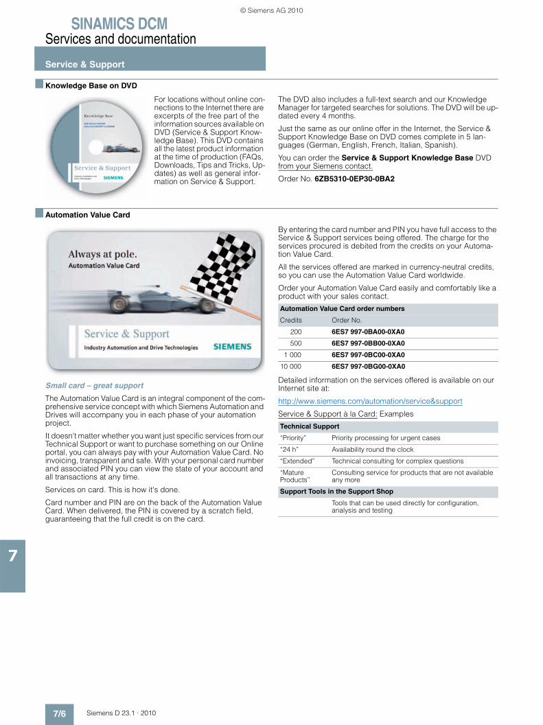
SINAMICS DCMServices and documentation
Service & Support
7/6 Siemens D 23.1 · 2010
7
■ Knowledge Base on DVD
For locations without online con-nections to the Internet there are excerpts of the free part of the information sources available on DVD (Service & Support Know-ledge Base). This DVD contains all the latest product information at the time of production (FAQs, Downloads, Tips and Tricks, Up-dates) as well as general infor-mation on Service & Support.
The DVD also includes a full-text search and our Knowledge Manager for targeted searches for solutions. The DVD will be up-dated every 4 months.
Just the same as our online offer in the Internet, the Service & Support Knowledge Base on DVD comes complete in 5 lan-guages (German, English, French, Italian, Spanish).
You can order the Service & Support Knowledge Base DVD from your Siemens contact.
Order No. 6ZB5310-0EP30-0BA2
■ Automation Value Card
Small card – great support
The Automation Value Card is an integral component of the com-prehensive service concept with which Siemens Automation and Drives will accompany you in each phase of your automation project.
It doesn't matter whether you want just specific services from our Technical Support or want to purchase something on our Online portal, you can always pay with your Automation Value Card. No invoicing, transparent and safe. With your personal card number and associated PIN you can view the state of your account and all transactions at any time.
Services on card. This is how it's done.
Card number and PIN are on the back of the Automation Value Card. When delivered, the PIN is covered by a scratch field, guaranteeing that the full credit is on the card.
By entering the card number and PIN you have full access to the Service & Support services being offered. The charge for the services procured is debited from the credits on your Automa-tion Value Card.
All the services offered are marked in currency-neutral credits, so you can use the Automation Value Card worldwide.
Order your Automation Value Card easily and comfortably like a product with your sales contact.
Detailed information on the services offered is available on our Internet site at:
http://www.siemens.com/automation/service&support
Service & Support à la Card: Examples
Automation Value Card order numbers
Credits Order No.
200 6ES7 997-0BA00-0XA0
500 6ES7 997-0BB00-0XA0
1 000 6ES7 997-0BC00-0XA0
10 000 6ES7 997-0BG00-0XA0
Technical Support
“Priority” Priority processing for urgent cases
“24 h” Availability round the clock
“Extended” Technical consulting for complex questions
“Mature Products”
Consulting service for products that are not available any more
Support Tools in the Support Shop
Tools that can be used directly for configuration, analysis and testing
© Siemens AG 2010
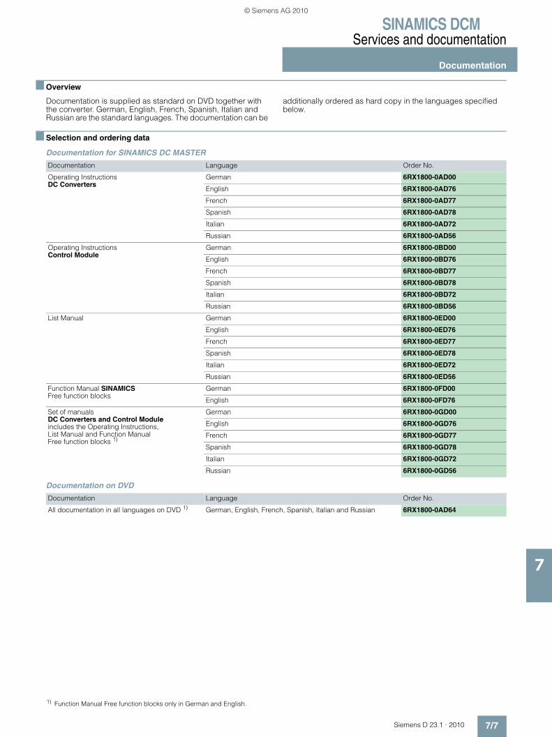
SINAMICS DCMServices and documentation
Documentation
7/7Siemens D 23.1 · 2010
7
■ Overview
Documentation is supplied as standard on DVD together with the converter. German, English, French, Spanish, Italian and Russian are the standard languages. The documentation can be
additionally ordered as hard copy in the languages specified below.
■ Selection and ordering data
Documentation for SINAMICS DC MASTER
Documentation on DVD
Documentation Language Order No.
Operating Instructions DC Converters
German 6RX1800-0AD00
English 6RX1800-0AD76
French 6RX1800-0AD77
Spanish 6RX1800-0AD78
Italian 6RX1800-0AD72
Russian 6RX1800-0AD56
Operating Instructions Control Module
German 6RX1800-0BD00
English 6RX1800-0BD76
French 6RX1800-0BD77
Spanish 6RX1800-0BD78
Italian 6RX1800-0BD72
Russian 6RX1800-0BD56
List Manual German 6RX1800-0ED00
English 6RX1800-0ED76
French 6RX1800-0ED77
Spanish 6RX1800-0ED78
Italian 6RX1800-0ED72
Russian 6RX1800-0ED56
Function Manual SINAMICS Free function blocks
German 6RX1800-0FD00
English 6RX1800-0FD76
Set of manuals DC Converters and Control Module includes the Operating Instructions, List Manual and Function ManualFree function blocks 1)
German 6RX1800-0GD00
English 6RX1800-0GD76
French 6RX1800-0GD77
Spanish 6RX1800-0GD78
Italian 6RX1800-0GD72
Russian 6RX1800-0GD56
Documentation Language Order No.
All documentation in all languages on DVD 1) German, English, French, Spanish, Italian and Russian 6RX1800-0AD64
1) Function Manual Free function blocks only in German and English.
© Siemens AG 2010

SINAMICS DCMServices and documentation
Notes
7/8 Siemens D 23.1 · 2010
7
© Siemens AG 2010

Siemens D 23.1 · 2010
88/2 Subject index
8/5 Order number index
8/6 List of abbreviations
8/7 Partner at Industry Automation andDrive Technologies
8/8 Online Services – Information and Ordering in the Internet and on DVD
8/8 Siemens Industry Automation and Drive Technologies in the WWW
8/8 Product Selection Using the Offline Mall of Industry
8/8 Easy Shopping with the Industry Mall
8/9 Conditions of sale and delivery
8/9 Export regulations
8/10 DVD-ROM included with Catalog D 23.1 · 2010
Appendix
© Siemens AG 2010
SINAMICS DCMAppendix
Subject index
8/2 Siemens D 23.1 · 2010
8
Part/PageAAccessories 4/1Accessories – Control Module 3/53Actual speed 3/4Advanced CUD 2/2, 3/32, 3/35, 4/4,
4/6, 4/9Advanced Operator Panel AOP30 3/10, 3/46, 4/2Analog outputs 3/48Analog user-assignable inputs 3/48AOP30 3/10, 3/46, 4/2Appendix 8/1Application – Control Module 3/51Application – DC Converter and
Control Module 3/3Approvals 3/11, 3/35, 4/4, 4/7,
4/10, 4/27Arm fuses 4/13 … 4/15Armature circuit, closed-loop control 3/4Armature circuit, fuses 4/12Armature supply 3/32, 3/36Assignment of terminals and connectors 3/39Automation Value Card 7/6Auto-reversing module 3/5Available options 3/32
BBasic information about EMC 5/22Basic Operator Panel BOP20 3/10, 3/45Benefits – DC Converter and
Control Module 3/3Binary inputs 3/48Binary outputs 3/48Block library for SIMATIC PCS7 6/7BOP20 3/10, 3/45Bridge circuit B6C and (B6)A(B6)C –
three-phase 5/28Brush length 3/49
CCable 5/21Cable length 5/21CBE20 3/32, 3/35Characteristic values of the pulse
tachometer evaluation electronics 5/21Characteristics – dynamic overload
capability 5/4 … 5/15Circuit-breakers 4/19Closed-loop control 3/46Closed-loop control in the armature circuit 3/4Closed-loop control in the field circuit 3/6Closed-loop control section 3/42Coated PCBs 2/3, 3/32, 3/36Commissioning SINAMICS DCM 7/4Commissioning tool STARTER 6/3Communication between drive
components 3/6Communication Board CBE20 3/32, 3/35Commutating reactors 4/16Components for converter units,
arrangement 5/27Components, supplementary 4/1Conditions of delivery 8/9Conditions of sale 8/9Configuration 1/12Connection, single-phase 2/3Connector Board 3/43Connectors 3/39Contact 8/7Contactors 4/19Control Module 3/51Control terminal block 3/49Control Units 3/37Coolant temperature 3/8Cooling 3/45Copper busbars, nickel-plated 2/3, 3/32, 3/36
Part/PageC (continued)CUD 2/2, 3/32, 3/35, 4/4Current controller 3/5Current limiting 3/5
DDC Converter 3/10, 3/38DC fuse 3/30, 3/31,
4/12 ... 4/15Description of options 3/35Design – Control Module 3/51Diagnostics 3/47Dimension drawings 8/10Documentation 3/9, 7/7Drive components, communication 3/6Drive Control Chart (DCC) 2/3, 3/45, 6/5Drive ES engineering software 6/6DRIVE-CLiQ 2/3, 3/6, 4/4, 4/5, 4/7Duty cycles for four-quadrant operation 5/18Duty cycles for two-quadrant operation 5/17DVD 8/8DVD-ROM included with
Catalog D 23.1 · 2010 8/10Dynamic overload capability 5/2
EElectronics power supply 2/3, 3/32, 3/36, 3/41EMC 5/22EMC-compliant drive installation 5/24EMF controller 3/6Engineering 6/1Engineering information 5/1Engineering software Drive ES 6/6Engineering Support 7/5Engineering tool SIZER LD web 6/2E-STOP 3/49Expandable functionality using SINAMICS
components 2/3Export regulations 8/9
FFans 3/32, 3/36, 3/42Field circuit 3/40Field circuit, closed-loop control 3/6Field circuit, fuses 4/12Field current controller 3/6Field power section 3/32, 3/36Field power supply 2/2Field power supply in line with
requirements 2/2Field Service 7/5Filters 4/19Free function blocks 2/3, 3/44Function blocks, free 2/3, 3/44Function of the inputs and outputs 3/48Functionality using SINAMICS
components 2/3Functions of the closed-loop control
in the armature circuit 3/4Functions of the closed-loop control
in the field circuit 3/6Fuses for the armature circuit 4/12Fuses for the field circuit 4/12
GGating unit 3/5, 3/6General information – DC Converter and
Control Module 3/2General technical data – DC Converter 3/11
HHands-on training from the manufacturer 7/3Harmonics 5/28High inductances, supply 5/20Highlights 2/1
© Siemens AG 2010

SINAMICS DCMAppendix
Subject index
8/3Siemens D 23.1 · 2010
8
Part/PageIIndustry Mall 0/6Information and Ordering in the Internet
and on DVD 8/8Input pulse levels 5/21Inputs, functions 3/48Installation altitude 3/8Interface to the motor 3/50Interfaces, serial 3/49Interference suppression filter 4/19Internet 8/8Introduction 1/1IP20 – mounting kit to upgrade 4/11
KKnowledge Base on DVD 7/6
LLevels, input pulses 5/21Line-side harmonics 5/28List of abbreviations 8/6Load classes 5/15, 5/16
MMall 0/6, 8/8Members of the SINAMICS drive family 1/6Memory card 3/32, 3/36Monitoring 3/47More information – DC Converter and
Control Module 3/9Motor fan airflow 3/50Motor temperature 3/50Mounting kit to upgrade to IP20 4/11
NNickel-plated copper busbars 2/3Notes for EMC-compliant installation 5/22
OOffline Mall 8/8Online services 8/8Online Support 7/5Open-loop control section 3/42Open-loop drive control 3/46Operation, 12-pulse 5/20Operation, single-phase 3/8Optimization 7/5Option selection matrix 3/33Options 3/32Options, description 3/35Order number index 8/5Ordering examples 3/34Outputs, functions 3/48Overload capability, dynamic 5/2Overview – DC Converter 3/10Overview – DC Converter and
Control Module 3/2Overview, closed-loop control structure 3/7Overvoltage protection 4/21
Part/PagePParallel connection of
SINAMICS DC MASTER units 5/19Parameterizing devices 3/45Peer-to-peer protocol 3/49Phase fuses 3/30, 3/31,
4/12 ... 4/15Platform concept and Totally Integrated
Automation 1/2Power section 3/39, 3/45Power section isolated with respect
to ground 2/3Precontrol 3/5Product Selection Using the Offline Mall
of Industry 8/8PROFIBUS as standard 2/2“PROFIBUS DP” communications software 6/7“PROFINET IO” communications software 6/7PROFINET optional 2/2Protection against condensation 5/20Pulse operation – 12-pulse 5/20Pulse tachometer evaluation electronics,
characteristic values 5/21
QQuality according to DIN EN ISO 9001 1/3
RRadio interference suppression filters 4/19, 5/26Radio interference suppression filters
from EPCOS 4/19Radio interference suppression filters
from Siemens 4/20Ramp-function generator 3/4Range of training courses 7/4Redundant operation 5/19Repairs 7/5Rules for EMC-compliant installation 5/24
SSafety shutdown (E-STOP) 3/49Schematics – Control Module 3/54Schematics – Control Units 3/37Schematics – DC Converter 3/38Schematics SIMOREG CCP 4/32, 4/33Selection and ordering data –
Control Module 3/52Selection and ordering data DC Converter
for four-quadrant operation 3/31Selection and ordering data DC Converter
for two-quadrant operation 3/30Selection matrix, options 3/33Sensor Module Cabinet-Mounted SMC30 4/4Sensors, external 3/32, 3/36Serial interfaces 3/49Service & Support 7/5Services 7/1SETUP program 6/7Shield connection 5/21, 5/26Shielding 5/25SICROWBAR AC 4/21 … 4/23SICROWBAR DC 4/24 … 4/27SICROWBAR overvoltage protection 4/21 … 4/27Siemens DC motors 3/50Siemens Industry Automation and
Drive Technologies in the WWW 8/8
© Siemens AG 2010

SINAMICS DCMAppendix
Subject index
8/4 Siemens D 23.1 · 2010
8
Part/PageS (continued)SIMOREG CCP 4/28SIMOREG CM 3/2SINAMICS DC converters 1/6SINAMICS DC MASTER for
12-pulse operation 5/20SINAMICS DC MASTER to supply
high inductances 5/20SINAMICS DCM 1/6SINAMICS DCM demonstration case 7/2SINAMICS DCM series of converters 1/10SINAMICS drive family 2/2SINAMICS G110 1/7SINAMICS G110D 1/7SINAMICS G120 1/7SINAMICS G120D 1/7SINAMICS G130, SINAMICS G150 1/8SINAMICS GL150 1/9SINAMICS GM150 1/9SINAMICS Link 3/6SINAMICS low-voltage converters 1/7SINAMICS medium-voltage converters 1/9SINAMICS S110 1/8SINAMICS S120 1/8SINAMICS S150 1/8SINAMICS SM150 1/9SINAMICS, members of the drive family 1/6SINAMICS, the drive family 1/2Single-phase connection 2/3Single-phase operation 3/8SITRAIN 7/3SIZER LD web engineering tool 6/2SMC30 4/4Spare Parts 7/5Speed controller 3/5Speed setpoint 3/4Standard CUD 2/2, 3/32, 3/35, 4/4Standards 3/10, 4/27, 5/22,
5/23STARTER commissioning tool 6/3STEP 7 device object manager 6/7STEP 7 slave object manager 6/7Supplementary components 4/1Supply of high inductances 5/20Switching frequency 5/21System components of a DC drive 1/11
Part/PageTTechnical Consulting 7/5Technical specifications – Control Module 3/52Technical specifications – DC Converter 3/10Technical specifications – SINAMICS DC
MASTER converters 3/12Technical Support 7/5Temperature range, wide 2/4Terminal Module TM15 4/5Terminal Module TM31 4/8Terminals 3/39Terminals on Connector Board 3/43The SINAMICS drive family 1/2Three-phase bridge circuit B6C and
(B6)A(B6)C 5/28TM15 4/5TM31 4/8Tools 6/1Torque limiting 3/5Totally Integrated Automation 0/4, 1/2Training 7/3
UUpgrade to IP20 4/11Upgrading 7/5USS protocol 3/49“USS-Protocol” communications software 6/7
VVariance of the Control Units 2/2
WWWW 8/8
© Siemens AG 2010

SINAMICS DCMAppendix
Order number index
8/5Siemens D 23.1 · 2010
8
Part/Page
3NE… Fuses 4/12 … 4/15
4EM… Commutating reactors 4/17
4EP… Commutating reactors 4/17, 4/18
4EU… Commutating reactors 4/17, 4/18
5SD… Fuse 4/12
6AU1810-1… Drive Control Chart (DCC) 6/5
6ES7901-4BD00-0XA0 Connecting cable between CP 5512 and PROFIBUS 6/46ES7997-… Automation Value Card 7/6
6GK1551-2AA00 PROFIBUS communication module CP 5512 6/4
6RA70… SIMOREG CCP 4/31
6RA8000-0MV62-0AA0 Control Module 3/526RA801… DC Converter for four-quadrant operation 3/316RA802… DC Converter for two-quadrant operation and four-quadrant operation 3/30, 3/316RA803… DC Converter for two-quadrant operation and four-quadrant operation 3/30, 3/316RA807… DC Converter for two-quadrant operation and four-quadrant operation 3/30, 3/316RA808… DC Converter for two-quadrant operation and four-quadrant operation 3/30, 3/316RA809… DC Converter for two-quadrant operation and four-quadrant operation 3/30, 3/31
6RX1800-0AD… Operating Instructions DC Converters 7/76RX1800-0AD64 All documentation in all languages on DVD 7/76RX1800-0BD… Operating Instructions Control Module 7/76RX1800-0ED… List Manual 7/76RX1800-0FD… Function Manual SINAMICS Free function blocks 7/76RX1800-0GD… Set of manuals DC Converters and Control Module 7/76RX1800-0MA… Mounting kit to upgrade to IP20 4/11
6RY1702-… Arm fuses 4/13, 4/14
6RY1707-0AA08 Patch cable UTP CAT5 4/316RY1707-0C… Pre-fabricated connection set 3/53
6RY1805-0CM00 Rear enclosure part including accessories 3/536RY1807-0A… RS485 cable to connect the AOP to a CUD or to two CUDs 4/36RY1807-0C... Pre-fabricated connection sets and mounting parts 3/53
6SL3055-0AA00-3AA1 TM31 Terminal Module 4/106SL3055-0AA00-3FA0 TM15 Terminal Module 4/76SL3055-0AA00-4CA4 AOP30 Advanced Operator Panel 4/36SL3055-0AA00-5CA2 SMC30 Sensor Module Cabinet-Mounted 4/46SL3060-… Pre-fabricated DRIVE-CLiQ cables 4/76SL3072-0AA00-0AG0 STARTER commissioning tool 6/3
6SW1700-… Drive ES engineering software 6/7, 6/8
7VV3002-… SICROWBAR AC overvoltage protection 4/237VV3003-… SICROWBAR DC overvoltage protection 4/27
© Siemens AG 2010

SINAMICS DCMAppendix
List of abbreviations
8/6 Siemens D 23.1 · 2010
8
Abbreviation Meaning
AC Alternating Current
AOP30 Advanced Operator Panel
AWG American Wire Gauge
BICO Binector/Connector Technology
BOD Break-Over Diode
BOP20 Basic Operator Panel
CBE Communication Board
CDS Command Data Set
CM Control Module
CU Control Unit
CUD Control Unit DC
DC Direct Current
DCB Drive Control Block
DCC Drive Control Chart
DCM DC MASTER
DDS Drive Data Set
DIN German Institute for Standardization (Deutsches Institut für Normung e.V.)
DRIVE-CLiQ Drive Component Link with IQ
EMC Electromagnetic Compatibility
EMF Electromotive Force
EN European standard (Europäische Norm)
EPROM Erasable Programmable Read Only Memory
E-STOP Emergency Stop
ES Engineering System
HTL High-level Transistor Logic
IEC International Electrotechnical Commission
IP International Protection
Abbreviation Meaning
LCD Liquid Crystal Display
LED Light Emitting Diode
MTBF Mean Time Between Failure
PC Personal Computer
PCB Printed Circuit Board
PCS Process Control System
PDS Power Drive System
PE Protective Earth
PG Programming device (Programmiergerät)
PKW Parameter identifier value (Parameter Kennung Wert)
PTC Positive Temperature Coefficient
PZD Process data (Prozessdaten)
RAM Random Access Memory
SMC30 Sensor Module
SSO Single Sign-On
TIA Totally Integrated Automation
TIP Totally Integrated Power
TM15, TM31 Terminal Module
TTL Transistor-Transistor Logic
UL Underwriters Laboratories Inc.
UPS Uninterruptible Power Supply
USS Universal serial interface (Universelle Serielle Schnittstelle)
VDE Association of Electrical Engineering, Electronics and Information Technology (Germany) (Verband der Elektrotechnik Elektronik Informationstechnik e.V.)
© Siemens AG 2010
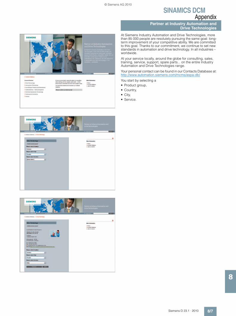
SINAMICS DCMAppendix
Partner at Industry Automation andDrive Technologies
8/7Siemens D 23.1 · 2010
8
At Siemens Industry Automation and Drive Technologies, more than 85 000 people are resolutely pursuing the same goal: long-term improvement of your competitive ability. We are committed to this goal. Thanks to our commitment, we continue to set new standards in automation and drive technology. In all industries – worldwide.
At your service locally, around the globe for consulting, sales, training, service, support, spare parts... on the entire Industry Automation and Drive Technologies range.
Your personal contact can be found in our Contacts Database at:http://www.automation.siemens.com/mcms/aspa-db/
You start by selecting a• Product group, • Country, • City, • Service.
© Siemens AG 2010

SINAMICS DCMAppendixOnline Services – Information and Ordering in the Internet and on DVD
8/8 Siemens D 23.1 · 2010
8
■ Siemens Industry Automation and Drive Technologies in the WWWA detailed knowledge of the range of products and services available is essential when planning and configuring automation systems. It goes without saying that this information must always be fully up-to-date.
Siemens Industry Automation and Drive Technologies has therefore built up a comprehensive range of information in the World Wide Web, which offers quick and easy access to all data required.
Under the address
http://www.siemens.com/automation
you will find everything you need to know about products, sys-tems and services.
■ Product Selection Using the Offline Mall of IndustryDetailed information together with convenient interactive functions: The Offline Mall CA 01 covers more than 80 000 products and thus provides a full summary of the Siemens Industry Automation and Drive Technologies product base.
Here you will find everything that you need to solve tasks in the fields of automation, switchgear, installation and drives. All information is linked into a user interface which is easy to work with and intuitive.
After selecting the product of your choice you can order at the press of a button, by fax or by online link.
Information on the Offline Mall CA 01 can be found in the Internet under
http://www.siemens.com/automation/ca01
or on DVD.
■ Easy Shopping with the Industry Mall The Industry Mall is the virtual department store of Siemens AG in the Internet. Here you have access to a huge range of prod-ucts presented in electronic catalogs in an informative and at-tractive way.
Data transfer via EDIFACT allows the whole procedure from selection through ordering to tracking of the order to be carried out online via the Internet.
Numerous functions are available to support you.
For example, powerful search functions make it easy to find the required products, which can be immediately checked for avail-ability. Customer-specific discounts and preparation of quotes can be carried out online as well as order tracking and tracing.
Please visit the Industry Mall in the Internet under:
http://www.siemens.com/industrymall
© Siemens AG 2010
SINAMICS DCMAppendix
Conditions of sale and deliveryExport regulations
8/9Siemens D 23.1 · 2010
8
■ Terms and Conditions of Sale and Delivery
By using this catalog you can acquire hardware and software products described therein from Siemens AG subject to the fol-lowing terms. Please note! The scope, the quality and the condi-tions for supplies and services, including software products, by any Siemens entity having a registered office outside of Ger-many, shall be subject exclusively to the General Terms and Conditions of the respective Siemens entity. The following terms apply exclusively for orders placed with Siemens AG.
For customers with a seat or registered office in GermanyThe “General Terms of Payment” as well as the “General Condi-tions for the Supply of Products and Services of the Electrical and Electronics Industry” shall apply.For software products, the “General License Conditions for Soft-ware Products for Automation and Drives for Customers with a Seat or registered Office in Germany” shall apply.
For customers with a seat or registered office outside of GermanyThe “General Terms of Payment” as well as the “General Condi-tions for Supplies of Siemens, Automation and Drives for Cus-tomers with a Seat or registered Office outside of Germany” shall apply.For software products, the “General License Conditions for Soft-ware Products for Automation and Drives for Customers with a Seat or registered Office outside of Germany” shall apply.
GeneralThe dimensions are in mm. In Germany, according to the Ger-man law on units in measuring technology, data in inches only apply to devices for export. Illustrations are not binding.Insofar as there are no remarks on the corresponding pages, – especially with regard to data, dimensions and weights given – these are subject to change without prior notice.The prices are in € (Euro) ex works, exclusive packaging.The sales tax (value added tax) is not included in the prices. It shall be debited separately at the respective rate according to the applicable legal regulations.Prices are subject to change without prior notice. We will debit the prices valid at the time of delivery.Surcharges will be added to the prices of products that contain silver, copper, aluminum, lead and/or gold if the respective basic official prices for these metals are exceeded. These surcharges will be determined based on the official price and the metal fac-tor of the respective product.The surcharge will be calculated on the basis of the official price on the day prior to receipt of the order or prior to the release order.The metal factor determines the official price as of which the metal surcharges are charged and the calculation method used. The metal factor, provided it is relevant, is included with the price information of the respective products.
An exact explanation of the metal factor and the text of the Comprehensive Terms and Conditions of Sale and Delivery are available free of charge from your local Siemens business office under the following Order Nos.:• 6ZB5310-0KR30-0BA1
(for customers based in Germany)• 6ZB5310-0KS53-0BA1
(for customers based outside Germany)or download them from the Internetwww.siemens.com/industrymall (Germany: Industry Mall Online-Help System)
■ Export regulations
The products listed in this catalog may be subject to European / German and/or US export regulations.Therefore, any export requiring a license is subject to approval by the competent authorities.According to current provisions, the following export regulations must be observed with respect to the products featured in this catalog:
Even without a label or with an “AL: N” or “ECCN: N”, authoriza-tion may be required due to the final destination and purpose for which the goods are to be used. The deciding factors are the AL or ECCN export authorization indicated on order confirmations, delivery notes and invoices.Errors excepted and subject to change without prior notice.
I IA/DT /VuL_ohne MZ/En 16.03.10
AL Number of the German Export ListProducts marked other than “N” require an export license. In the case of software products, the export des-ignations of the relevant data medium must also be generally adhered to.Goods labeled with an “AL” not equal to “N” are subject to a European or German export authori-zation when being exported out of the EU.
ECCN Export Control Classification NumberProducts marked other than “N” are subject to a reexport license to specific countries.In the case of software products, the exportdesignations of the relevant data medium must also be generally adhered to.Goods labeled with an “ECCN” not equal to “N” are subject to a US re-export authorization.
© Siemens AG 2010

SINAMICS DCMAppendix
DVD-ROM included with Catalog D 23.1 · 2010
8/10 Siemens D 23.1 · 2010
8
On the DVD-ROM included with Catalog D 23.1 · 2010, you will find:• Manuals, SINAMICS DCM and SICROWBAR AC/DC• GSD files• Function block diagrams in the VSD format• Dimension drawings of the DC Converter and Control Module
in the DXF and PDF formats• STARTER commissioning tool• Spare parts list in the XLS format• Catalog D 23.1 · 2010 in the PDF format• Information about service and support
The contents of the DVD correspond to the catalog edition. Current versions are provided in the Internet and on every DVD supplied with the equipment.
Hardware and software requirements• DVD-ROM drive• Windows from XP• Adobe Reader from 7.0• MS Internet Explorer from V6.0 (SP2)
Start
Insert the DVD-ROM into your DVD-ROM drive. Run the “start.htm” file from the DVD-ROM in your Windows Explorer.
Note:No software has to be installed to view the information on this DVD-ROM. The only exception is when using the dimension drawings in the DXF format.
© Siemens AG 2010

CatalogsIndustry Automation, Drive Technologies and Low Voltage Distribution
Further information can be obtained from our branch offices listedin the appendix or at www.siemens.com/automation/partner
IA DT LV/3U/En 26.03.10
Interactive Catalog on DVD Catalogfor Industry Automation, Drive Technologies and Low Voltage Distribution
CA 01
Drive SystemsVariable-Speed Drives
SINAMICS G110, SINAMICS G120 Standard Inverters SINAMICS G110D, SINAMICS G120D Distributed Inverters
D 11.1
SINAMICS G130 Drive Converter Chassis Units SINAMICS G150 Drive Converter Cabinet Units
D 11
SINAMICS GM150, SINAMICS SM150 Medium-Voltage Converters
D 12
SINAMICS S120 Chassis Format Units and Cabinet Modules SINAMICS S150 Converter Cabinet Units
D 21.3
SINAMICS DCM Converter Units D 23.1
Three-phase Induction Motors• H-compact• H-compact PLUS
D 84.1
Asynchronous Motors Standardline D 86.1
Synchronous Motors with Permanent-Magnet Technology, HT-direct
D 86.2
DC Motors DA 12
SIMOREG DC-MASTER 6RA70 Digital Chassis Converters
DA 21.1
SIMOREG K 6RA22 Analog Chassis Converters DA 21.2
PDF: SIMOREG DC-MASTER 6RM70 Digital Converter Cabinet Units
DA 22
SIMOVERT PM Modular Converter Systems DA 45
SIEMOSYN Motors DA 48
MICROMASTER 420/430/440 Inverters DA 51.2
MICROMASTER 411/COMBIMASTER 411 DA 51.3
SIMOVERT MASTERDRIVES Vector Control DA 65.10
SIMOVERT MASTERDRIVES Motion Control DA 65.11
Synchronous and asynchronous servomotors for SIMOVERT MASTERDRIVES
DA 65.3
SIMODRIVE 611 universal and POSMO DA 65.4
SIMOTION, SINAMICS S120 and Motors for Production Machines
PM 21
SINAMICS S110 The Basic Positioning Drive
PM 22
Low-Voltage Three-Phase-Motors
IEC Squirrel-Cage Motors D 81.1
MOTOX Geared Motors D 87.1
Automation Systems for Machine Tools SIMODRIVE• Motors• Converter Systems SIMODRIVE 611/POSMO
NC 60
Automation Systems for Machine Tools SINAMICS• Motors• Drive System SINAMICS S120
NC 61
Drive and Control Components for Hoisting Equipment HE 1
Mechanical Driving Machines
Flender Standard Couplings MD 10.1
Electrical Installation TechnologyPDF: ALPHA Distribution Boards and Terminal Blocks ET A1
PDF: ALPHA 8HP Molded-Plastic Distribution System ET A3
PDF: BETA Low-Voltage Circuit Protection ET B1
PDF: DELTA Switches and Socket Outlets ET D1
PDF: GAMMA Building Management Systems ET G1
PDF: These catalogs are only available as pdf files.
Motion Control Catalog
SINUMERIK & SIMODRIVE Automation Systems for Machine Tools
NC 60
SINUMERIK & SINAMICS Equipment for Machine Tools
NC 61
SIMOTION, SINAMICS S120 and Motors for Production Machines
PM 21
SINAMICS S110 The Basic Positioning Drive
PM 22
Low-VoltageControls and Distribution – SIRIUS, SENTRON, SIVACON
LV 1
SICUBE System Cubicles and Cubicle Air-Conditioning LV 50
PDF: SIDAC Reactors and Filters LV 60
PDF: SIVACON 8PS Busbar Trunking Systems LV 70
Low-Voltage Controls and Distribution – SIRIUS, SENTRON, SIVACON
LV 90
Power Supply and System CablingPower supply SITOP KT 10.1
System cabling SIMATIC TOP connect KT 10.2
Process Instrumentation and AnalyticsField Instruments for Process Automation FI 01
PDF: Indicators for panel mounting MP 12
SIREC Recorders and Accessories MP 20
SIPART, Controllers and Software MP 31
PDF: Products for Weighing Technology WT 10
Process Analytical Instruments PA 01
PDF: Process Analytics, Components for the System Integration
PA 11
Safety IntegratedSafety Technology for Factory Automation SI I0
SIMATIC HMIHuman Machine Interface Systems ST 80
SIMATIC Industrial Automation SystemsProducts for Totally Integrated Automation and Micro Automation
ST 70
SIMATIC PCS 7 Process Control System ST PCS 7
Add-ons for the SIMATIC PCS 7 Process Control System
ST PCS 7.1
PDF: Migration solutions with the SIMATIC PCS 7 Process Control System
ST PCS 7.2
pc-based Automation ST PC
SIMATIC NETIndustrial Communication IK PI
SIMATIC SensorsSensor Technology for Factory Automation FS 10
Industrial Identification Systems ID 10
System SolutionsApplications and Products for Industry are part of the interactive catalog CA 01
© Siemens AG 2010

www.siemens.com/sinamics
Subject to change without prior noticeOrder No. E86060-K5523-A111-A1-76003P.8222.88.12 / Dispo 18402KG 0510 6.0 E 168 EnPrinted in Germany © Siemens AG 2010
Siemens AGIndustry SectorDrive Technologies Division Large DrivesPostfach 48 4890026 NÜRNBERGGERMANY
The information provided in this catalog contains descriptions or characteristics of performance which in case of actual use do not always apply as described or which may change as a result of further development of the products. An obligation to provide the respective characteristics shall only exist if expressly agreed in the terms of contract. Availability and technical specifications are subject to change without notice.All product designations may be trademarks or product names of Siemens AG or supplier companies whose use by third parties for their own purposes could violate the rights of the owners.
Token fee: 5.00 €
© Siemens AG 2010

Cat
alo
g D
23
.1 ·
20
10
SIN
AM
ICS
DC
M C
on
vert
er U
nit
s© Siemens AG 2010