catalog | copper cables · 1st issue specifications are subject to change without notice. the data...
TRANSCRIPT
Copper Cablescatalog | A l u m i n u m S h i e l dAluminum Steel ShieldCopper Clad ShieldCopper Shield
AlFOUR AsFOUR
CasFOUR CoFOUR
| | | |

Copper Cablescatalog | A l u m i n u m S h i e l dAlFOUR |

Sp
eci
fica
tions
are
sub
ject
to c
ha
ng
e w
ithout
prior
notice
. 4
SPro
duct
s ca
ble
s a
re d
esi
gned
and
test
ed
to m
eet
AN
SI/I
CEA
req
uirem
ents
.
Conductors:
Insulation:
Twisted Pairs:
Core Assembly:
Core Wrap:
Shielding:
Jacket:
Jacket Markings:
Optional Designs:
Solid annealed copper in 19, 22,24 and 26 AWG.
Conductors are insulated withsolid polyolefin, color coded in accordancewith industry standards.
Individual conductors aretwisted into pairs with varying lay lengths tominimize crosstalk and specific colorcombinations to provide pair identification.
Cables of 25 pairs or lessare assembled into a cylindrical core. Cableslarger than 25 pairs are assembled intounits, which are then used to assemble thecore. Units are individually identifiable bycolor coded unit binders.
A non-hygroscopic, dielectrictape is applied over the core assembly toprovide protection for the core.
A corrugated, copolymer coated,8-mil aluminum tape is applied longitudinallywith an overlap.
A black, linear low-densitypolyethylene jacket is applied overall. Thejacket provides a tough protective coveringdesigned to withstand exposure to directsunlight, atmospheric temperature changesand stresses expected in standardinstallations.
Information such asmanufacturer’s identification, pair countAWG, product identification and a telephonehandset is printed at 2 ft. intervals on thecable jacket. Sequential footage markingsare printed at alternate 2 ft. intervals.
ALFOUR® cables are alsoavailable with an internal screen for use withcarrier T1 systems.
Cable cut-away
Applications
4SProducts ALFOUR® cables are designed primarily foraerial use. In addition, they are also commonly used forburied applications. In an aerial application, the cablemust be attached to a support strand (messenger).ALFOUR® cables, in 19, 22, 24 and 26 AWG, are capableof meeting the electrical requirements of 100 ohms,Category 3, Backbone UTP cables as specified in TIA/EIA-568-A.
www.4SProducts.com
4621 Ponce de Leon BoulevardCoral Gables, FL 33146, USA[1] 305.666.7474[1] 305.666.7272 [email protected] e-mail
1st iSSUE
Qualifications & Approvals
Manufactured to meet requirements of ANSI/ICEA S-85-625-2002; formerly manufactured to REA Specification PE-22 (PE-22was deactivated by RUS and is superseded by ANSI/ICEAspecifications).
Description
4SProductsCopper Cable Assemblies A FOURL
®
Outside Plant Copper Cable - Exchange Cable
Pair Count 6 - 2400P
Aluminum Shield |Single Jacket | AirCoreTechnical
Data Sheet

Average mutual capacitance @ 1000 Hz
12 or LessOver 12
ConductorSize
52± 452± 2
AverageMaximum
Attenuation
68 °F (20 °C)772 kHz
MaximumConductorResistance
68 °F (20 °C)(ohms)
ResistanceUnbalance
Maximum
DielectricStrength
DCPotential Volts
Minimum
AWGGigohm/
milemm dB/kft dB/km mile km Avg %
Gigohm/km
Individualpair %
Cdr toCdr
Cdr toGround
19
22
24
26
0.90
0.64
0.50
0.40
1.0
1.0
1.0
1.0
1.6
1.6
1.6
1.6
3.3
4.6
5.7
7.2
10.9
15.3
19.4
23.6
45.0
91.0
144.0
232.0
28.0
56.5
89.5
144.2
1.5
1.5
1.5
1.5
5.0
5.0
5.0
5.0
5,000
4,000
3,000
2,400
10,000
10,000
10,000
10,000
Maximum individual Maximum RMS
pF/kft pF/km pF/kft pF/kmPairs
12 or Less
more than 12
80
80
145
145
-
25
-
45
Capacitance unbalance Pair-to-Pair
Total No.of pairs
nF/mile nF/km
Maximum individual Maximum RMS
pF/kft pF/km pF/kft pF/kmPairs
12 or Less
more than 12
800
800
2625
2625
-
175
-
574
Capacitance unbalance Pair-to-Ground
772 kHz
47
42
Near End Crosstalk (NEXT) 150 kHz
26
61
57
58
53
P.S. WUNEXT mean (dB)
P.S. WUNEXT worst pair (dB)
24
63
57
22
63
57
19
65
59
Conductor size (AWG)
P.S. ELFEXT mean (dB)
P.S. ELFEXT worst pair (dB)
Far End Crosstalk (FEXT) @ 150 kHz
26
47
43
24
49
43
22
49
43
19
51
45
Conductor size (AWG)
P.S. ELFEXT mean (dB)
P.S. ELFEXT worst pair (dB)
Far End Crosstalk (FEXT) @ 772 kHz
83± 783± 4
MinimumInsulationResistance
68 °F (20 °C)
1st iSSUE
Specifications are subject to change without notice. The data given is subject to normalmanufacturing tolerances. 4SProducts Copper Communication Cables are
designed and tested in accordance with the requirements of ANSI/ICEA.
4SProductsCopper Cable Assemblies A FOURL
®
Outside Plant Copper Cable - Exchange Cable
Pair Count 6 - 2400P
Aluminum Shield | Single Jacket | AirCoreTechnical
Data Sheet

Sp
eci
fica
tions
are
sub
ject
to c
ha
ng
e w
ithout
prior
notice
. 4
SPro
duct
s ca
ble
s a
re d
esi
gned
and
test
ed
to m
eet
AN
SI/I
CEA
req
uirem
ents
.
Conductors:
Insulation:
Twisted Pairs:
Core Assembly:
Core Wrap:
Shielding:
Outer Jacket:
Jacket Markings:
Solid annealed copper in 19, 22, 24 and26 AWG.
Conductors are insulated with solidpolyolefin, color coded in accordance with industrystandards.
Individual conductors are twisted intopairs with varying lay lengths to minimize crosstalk andspecific color combinations to provide pair identification.
Cables of 25 pairs or less areassembled into a cylindrical core. Cables larger than 25pairs are assembled into units, which are then used toassemble the core. Units are individually identifiable bycolor coded unit binders.
A non-hygroscopic, dielectric tape isapplied over the core assembly to provide protectionfor the core.
A corrugated, copolymer coated, 8-milaluminum tape is applied longitudinally with anoverlap.
A black, linear low-density polyethylenejacket is applied overall. The jacket provides a toughprotective covering designed to withstand exposure todirect sunlight, atmospheric temperature changes andstresses expected in standard installations.
Information, such as manufacturer'sidentification, pair count, AWG, product identificationand a telephone handset is printed at 2 ft. intervals onthe cable jacket. Sequential footage markings areprinted at alternate 2 ft. intervals.
Inner Jacket: A black polyethylene jacket.
Cable cut-away
Applications
4SProducts ALFOUR®- cables are designed for direct burial orduct applications where protection from moisture is required.ALFOUR®- cables may be used aerially, but must be attachedto a support strand (messenger). ALFOUR®- cables, in 19, 22,24 and 26 AWG, are capable of meeting the electricalrequirements of 100 ohms, Category 3, Backbone UTP Cablesas specified in TIA/EIA-568-A.
2
2
2
www.4SProducts.com
4621 Ponce de Leon BoulevardCoral Gables, FL 33146, USA[1] 305.666.7474[1] 305.666.7272 [email protected] e-mail
1st iSSUE
Qualifications & Approvals
Manufactured to meet requirements of ANSI/ICEA S-85-625-2002; formerly manufactured to REA Specification PE-22 (PE-22was deactivated by RUS and is superseded by ANSI/ICEAspecifications).
Description
4SProductsCopper Cable Assemblies A FOUR -L 2
®
Outside Plant Copper Cable - Exchange Cable
Pair Count 6 - 2400P
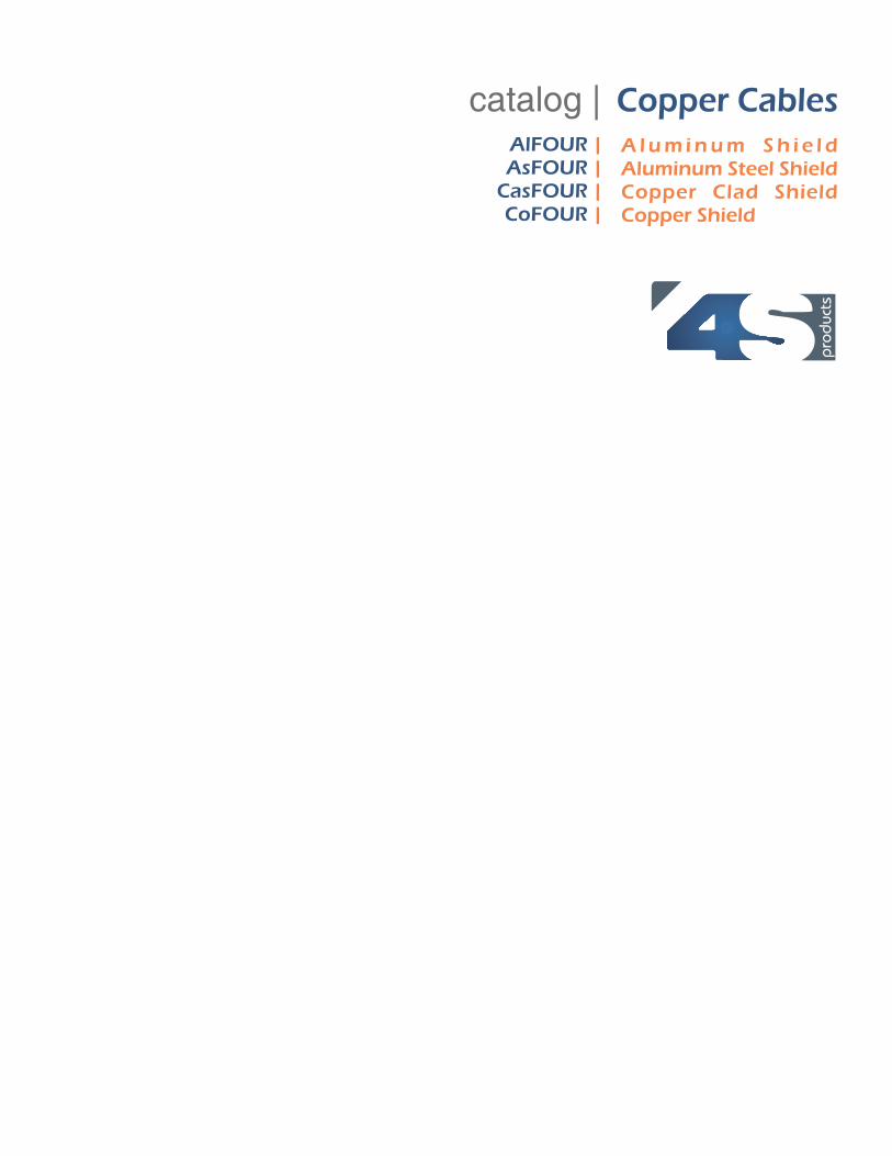
Aluminum Shield | Double Jacket | AirCoreTechnical
Data Sheet
1st iSSUE
Specifications are subject to change without notice. The data given is subject to normalmanufacturing tolerances. 4SProducts Copper Communication Cables are
designed and tested in accordance with the requirements of ANSI/ICEA.
4SProductsCopper Cable Assemblies A FOUR -L 2
®
Outside Plant Copper Cable - Exchange Cable
Pair Count 6 - 2400P
Aluminum Shield | Double Jacket | AirCoreTechnical
Data Sheet
Average mutual capacitance @ 1000 Hz
12 or LessOver 12
ConductorSize
52± 452± 2
AverageMaximum
Attenuation
68 °F (20 °C)772 kHz
MaximumConductorResistance
68 °F (20 °C)(ohms)
ResistanceUnbalance
Maximum
DielectricStrength
DCPotential Volts
Minimum
AWGGigohm/
milemm dB/kft dB/km mile km Avg %
Gigohm/km
Individualpair %
Cdr toCdr
Cdr toGround
19
22
24
26
0.90
0.64
0.50
0.40
1.0
1.0
1.0
1.0
1.6
1.6
1.6
1.6
3.3
4.6
5.7
7.2
10.9
15.3
19.4
23.6
45.0
91.0
144.0
232.0
28.0
56.5
89.5
144.2
1.5
1.5
1.5
1.5
5.0
5.0
5.0
5.0
5,000
4,000
3,000
2,400
10,000
10,000
10,000
10,000
Maximum individual Maximum RMS
pF/kft pF/km pF/kft pF/kmPairs
12 or Less
more than 12
80
80
145
145
-
25
-
45
Capacitance unbalance Pair-to-Pair
Total No.of pairs
nF/mile nF/km
Maximum individual Maximum RMS
pF/kft pF/km pF/kft pF/kmPairs
12 or Less
more than 12
800
800
2625
2625
-
175
-
574
Capacitance unbalance Pair-to-Ground
772 kHz
47
42
Near End Crosstalk (NEXT) 150 kHz
26
61
57
58
53
P.S. WUNEXT mean (dB)
P.S. WUNEXT worst pair (dB)
24
63
57
22
63
57
19
65
59
Conductor size (AWG)
P.S. ELFEXT mean (dB)
P.S. ELFEXT worst pair (dB)
Far End Crosstalk (FEXT) @ 150 kHz
26
47
43
24
49
43
22
49
43
19
51
45
Conductor size (AWG)
P.S. ELFEXT mean (dB)
P.S. ELFEXT worst pair (dB)
Far End Crosstalk (FEXT) @ 772 kHz
83± 783± 4
MinimumInsulationResistance
68 °F (20 °C)

Sp
eci
fica
tions
are
sub
ject
to c
ha
ng
e w
ithout
prior
notice
. 4
SPro
duct
s ca
ble
s a
re d
esi
gned
and
test
ed
to m
eet
AN
SI/I
CEA
req
uirem
ents
.
Conductors:
Insulation:
Twisted Pairs:
Core Assembly:
Filling Compound:
Core Wrap:
Shielding:
Jacket:
Jacket Markings:
Optional Designs:
Solid annealed copper in 19, 22, 24 and26 AWG.
Conductors are insulated with solidpolyolefin, color coded in accordance with industrystandards.
Individual conductors are twisted intopairs with varying lay lengths to minimize crosstalk andspecific color combinations to provide pair identification.
Cables of 25 pairs or less areassembled into a cylindrical core. Cables larger than 25pairs are assembled into units, which are then used toassemble the core. Units are individually identifiable bycolor coded unit binders.
The core assembly is filled with an80° C ETPR compound, completelyfilling the interstices between the pairs and under thecore wrap.
A non-hygroscopic, dielectric tape isapplied over the core assembly to provide protectionfor the core.
A corrugated, copolymer coated, 8-milaluminum tape is applied longitudinally with anoverlap. The shield interfaces are flooded with anadhesive compound to provide a moisture barrier andinhibit corrosion.
A black, linear low-density polyethylene jacketis applied overall. The jacket provides a toughprotective covering designed to withstand exposure todirect sunlight, atmospheric temperature changes andstresses expected in standard installations.
Information, such as manufacturer'sidentification, pair count, AWG, product identificationand a telephone handset is printed at 2 ft. intervals onthe cable jacket. Sequential footage markings areprinted at alternate 2 ft. intervals.
ALFOUR®-F cables are alsoavailable with an internal screen for use with T-Carriersystems.
or PIB base jelly
Cable cut-away
Applications
4SProducts ALFOUR®-F cables are designed for direct burial orduct applications where protection from moisture is required.ALFOUR®-F cables may be used aerially, but must be attachedto a support strand (messenger). ALFOUR®-F cables, in 19, 22,24 and 26 AWG, are capable of meeting the electricalrequirements of 100 ohms, Category 3, Backbone UTP Cablesas specified in TIA/EIA-568-A.
www.4SProducts.com
4621 Ponce de Leon BoulevardCoral Gables, FL 33146, USA[1] 305.666.7474[1] 305.666.7272 [email protected] e-mail
1st iSSUE
Qualifications & Approvals
Manufactured to meet requirements of ANSI/ICEA S-84-608-2002, RUS 7 CFR 1755.390 (PE-39).
Description
4SProductsCopper Cable Assemblies A FOUR -fL
®
Outside Plant Copper Cable - Exchange Cable
Pair Count 6 - 1800P
Aluminum Shield | Single Jacket | Filled - GelTechnical
Data Sheet

Average mutual capacitance @ 1000 Hz
12 or LessOver 12
ConductorSize
52± 452± 2
AverageMaximum
Attenuation
68 °F (20 °C)772 kHz
MaximumConductorResistance
68 °F (20 °C)(ohms)
ResistanceUnbalance
Maximum
DielectricStrength
DCPotential Volts
Minimum
AWGGigohm/
milemm dB/kft dB/km mile km Avg %
Gigohm/km
Individualpair %
Cdr toCdr
Cdr toGround
19
22
24
26
0.90
0.64
0.50
0.40
1.0
1.0
1.0
1.0
1.6
1.6
1.6
1.6
2.8
4.0
5.0
6.4
9.2
13.1
16.4
21.0
45.0
91.0
144.0
232.0
28.0
56.5
89.5
144.0
1.5
1.5
1.5
1.5
5.0
5.0
5.0
5.0
7,000
5,000
4,000
2,800
15,000
15,000
15,000
15,000
Maximum individual Maximum RMS
pF/kft pF/km pF/kft pF/kmPairs
12 or Less
more than 12
80
80
145
145
-
25
-
45
Capacitance unbalance Pair-to-Pair
Total No.of pairs
nF/mile nF/km
Maximum individual Maximum RMS
pF/kft pF/km pF/kft pF/kmPairs
12 or Less
more than 12
800
800
2625
2625
-
175
-
574
Capacitance unbalance Pair-to-Ground
772 kHz
47
42
Near End Crosstalk (NEXT) 150 kHz
26
61
57
58
53
P.S. WUNEXT mean (dB)
P.S. WUNEXT worst pair (dB)
24
63
57
22
63
57
19
65
59
Conductor size (AWG)
P.S. ELFEXT mean (dB)
P.S. ELFEXT worst pair (dB)
Far End Crosstalk (FEXT) @ 150 kHz
26
47
43
24
49
43
22
49
43
19
51
45
Conductor size (AWG)
P.S. ELFEXT mean (dB)
P.S. ELFEXT worst pair (dB)
Far End Crosstalk (FEXT) @ 772 kHz
83± 783± 4
MinimumInsulationResistance
68 °F (20 °C)
1st iSSUE
Specifications are subject to change without notice. The data given is subject to normalmanufacturing tolerances. 4SProducts Copper Communication Cables are
designed and tested in accordance with the requirements of ANSI/ICEA.
4SProductsCopper Cable Assemblies A FOUR -fL
®
Outside Plant Copper Cable - Exchange Cable
Pair Count 6 - 1800P
Aluminum Shield | Single Jacket | Filled - GelTechnical
Data Sheet

Sp
eci
fica
tions
are
sub
ject
to c
ha
ng
e w
ithout
prior
notice
. 4
SPro
duct
s ca
ble
s a
re d
esi
gned
and
test
ed
to m
eet
AN
SI/I
CEA
req
uirem
ents
.
Conductors:
Insulation:
Twisted Pairs:
Core Assembly:
Filling Compound:
Core Wrap:
Shielding:
Outer Jacket:
Jacket Markings:
Solid annealed copper in 19, 22, 24 and26 AWG.
Conductors are insulated with solidpolyolefin, color coded in accordance with industrystandards.
Individual conductors are twisted intopairs with varying lay lengths to minimize crosstalk andspecific color combinations to provide pair identification.
Cables of 25 pairs or less areassembled into a cylindrical core. Cables larger than 25pairs are assembled into units, which are then used toassemble the core. Units are individually identifiable bycolor coded unit binders.
The core assembly is filled with an80° C ETPR compound, completelyfilling the interstices between the pairs and under thecore wrap.
A non-hygroscopic, dielectric tape isapplied over the core assembly to provide protectionfor the core.
A corrugated, copolymer coated, 8-milaluminum tape is applied longitudinally with anoverlap. The shield interfaces are flooded with anadhesive compound to provide a moisture barrier andinhibit corrosion.
A black, linear low-density polyethylenejacket is applied overall. The jacket provides a toughprotective covering designed to withstand exposure todirect sunlight, atmospheric temperature changes andstresses expected in standard installations.
Information, such as manufacturer'sidentification, pair count, AWG, product identificationand a telephone handset is printed at 2 ft. intervals onthe cable jacket. Sequential footage markings areprinted at alternate 2 ft. intervals.
or PIB base jelly
A black polyethylene jacket.Inner Jacket:
Cable cut-away
Applications
4SProducts ALFOUR®- F cables are designed for direct burialor duct applications where protection from moisture is required.ALFOUR®- F cables may be used aerially, but must beattached to a support strand (messenger). ALFOUR®- Fcables, in 19, 22, 24 and 26 AWG, are capable of meeting theelectrical requirements of 100 ohms, Category 3, Backbone UTPCables as specified in TIA/EIA-568-A.
2
2
2
www.4SProducts.com
4621 Ponce de Leon BoulevardCoral Gables, FL 33146, USA[1] 305.666.7474[1] 305.666.7272 [email protected] e-mail
1st iSSUE
Qualifications & Approvals
Manufactured to meet requirements of ANSI/ICEA S-84-608-2002, RUS 7 CFR 1755.390 (PE-39).
Description
4SProductsCopper Cable Assemblies A FOUR - fL 2
®
Outside Plant Copper Cable - Exchange Cable
Pair Count 6 - 1800P
Aluminum Shield | Double Jacket | Filled - GelTechnical
Data Sheet
INNER JACKETPolyethylene

Average mutual capacitance @ 1000 Hz
12 or LessOver 12
ConductorSize
52± 452± 2
AverageMaximum
Attenuation
68 °F (20 °C)772 kHz
MaximumConductorResistance
68 °F (20 °C)(ohms)
ResistanceUnbalance
Maximum
DielectricStrength
DCPotential Volts
Minimum
AWGGigohm/
milemm dB/kft dB/km mile km Avg %
Gigohm/km
Individualpair %
Cdr toCdr
Cdr toGround
19
22
24
26
0.90
0.64
0.50
0.40
1.0
1.0
1.0
1.0
1.6
1.6
1.6
1.6
2.8
4.0
5.0
6.4
9.2
13.1
16.4
21.0
45.0
91.0
144.0
232.0
28.0
56.5
89.5
144.0
1.5
1.5
1.5
1.5
5.0
5.0
5.0
5.0
7,000
5,000
4,000
2,800
15,000
15,000
15,000
15,000
Maximum individual Maximum RMS
pF/kft pF/km pF/kft pF/kmPairs
12 or Less
more than 12
80
80
145
145
-
25
-
45
Capacitance unbalance Pair-to-Pair
Total No.of pairs
nF/mile nF/km
Maximum individual Maximum RMS
pF/kft pF/km pF/kft pF/kmPairs
12 or Less
more than 12
800
800
2625
2625
-
175
-
574
Capacitance unbalance Pair-to-Ground
772 kHz
47
42
Near End Crosstalk (NEXT) 150 kHz
26
61
57
58
53
P.S. WUNEXT mean (dB)
P.S. WUNEXT worst pair (dB)
24
63
57
22
63
57
19
65
59
Conductor size (AWG)
P.S. ELFEXT mean (dB)
P.S. ELFEXT worst pair (dB)
Far End Crosstalk (FEXT) @ 150 kHz
26
47
43
24
49
43
22
49
43
19
51
45
Conductor size (AWG)
P.S. ELFEXT mean (dB)
P.S. ELFEXT worst pair (dB)
Far End Crosstalk (FEXT) @ 772 kHz
83± 783± 4
MinimumInsulationResistance
68 °F (20 °C)
1st iSSUE
Specifications are subject to change without notice. The data given is subject to normalmanufacturing tolerances. 4SProducts Copper Communication Cables are
designed and tested in accordance with the requirements of ANSI/ICEA.
4SProductsCopper Cable Assemblies A FOUR - fL 2
®
Outside Plant Copper Cable - Exchange Cable
Pair Count 6 - 1800P
Aluminum Shield | Double Jacket | Filled - GelTechnical
Data Sheet

Sp
eci
fica
tions
are
sub
ject
to c
ha
ng
e w
ithout
prior
notice
. 4
SPro
duct
s ca
ble
s a
re d
esi
gned
and
test
ed
to m
eet
AN
SI/I
CEA
req
uirem
ents
.
Conductors:
Insulation:
Twisted Pairs:
Core Assembly:
Filling Compound:
Core Wrap:
Shielding:
Jacket:
Jacket Markings:
Optional Designs:
Solid annealed copper in 19, 22, 24 and26 AWG.
Conductors are dual insulated with an innerlayer of foamed, natural polyolefin covered by anouter layer of solid, colored polyolefin. The conductorinsulation is color coded in accordance with industrystandards.
Individual conductors are twisted intopairs with varying lay lengths to minimize crosstalk andspecific color combinations to provide pairidentification.
Cables of 25 pairs or less areassembled into a cylindrical core. Cables larger than 25pairs are assembled into units, which are then used toassemble the core. Units are individually identifiable bycolor coded unit binders.
The core assembly is filled with an80° C ETPR compound, completelyfilling the interstices between the pairs and under thecore wrap.
A non-hygroscopic, dielectric tape isapplied over the core assembly to provide protectionfor the core.
A corrugated, copolymer coated, 8-milaluminum tape is applied longitudinally with anoverlap. The shield interfaces are flooded with anadhesive compound to provide a moisture barrier andinhibit corrosion.
A black, linear low-density polyethylene jacketis applied overall. The jacket provides a toughprotective covering designed to withstand exposure todirect sunlight, atmospheric temperature changes andstresses expected in standard installations.
Information such as manufacturer'sidentification, pair count, AWG, product identificationand a telephone handset is printed at 2 ft. intervals onthe cable jacket. Sequential footage markings areprinted at alternate 2 ft. intervals.
ALFOUR®-FS cables are alsoavailable with an internal screen for use with T-Carriersystems. ALFOUR®-FS cables are also available with
or PIB base jelly
Cable cut-away
Applications
4SProducts ALFOUR®-FS cables are designed for direct burialor duct applications where protection from moisture is required.ALFOUR®-FS cables may be used aerially, but must beattached to a support strand (messenger). ALFOUR®-FScables, in 19, 22, 24 and 26 AWG, are capable of meeting theelectrical requirements of 100 ohms, Category 3, Backbone UTPCables as specified in TIA/EIA-568-A.
www.4SProducts.com
4621 Ponce de Leon BoulevardCoral Gables, FL 33146, USA[1] 305.666.7474[1] 305.666.7272 [email protected] e-mail
1st iSSUE
Qualifications & Approvals
Manufactured to meet requirements of ANSI/ICEA S-84-608-2002, RUS 7 CFR 1755.890 (PE-89).
Description
4SProductsCopper Cable Assemblies
Outside Plant Copper Cable - Exchange Cable
Pair Count 6 - 2400P
Aluminum Shield | Single Jacket | Filled - Foam SkinTechnical
Data Sheet
A FOUR -fSL®

1st iSSUE
Specifications are subject to change without notice. The data given is subject to normalmanufacturing tolerances. 4SProducts Copper Communication Cables are
designed and tested in accordance with the requirements of ANSI/ICEA.
4SProductsCopper Cable Assemblies
Outside Plant Copper Cable - Exchange Cable
Pair Count 6 - 2400P
Aluminum Shield | Single Jacket | Filled - Foam SkinTechnical
Data Sheet
Average mutual capacitance @ 1000 Hz
12 or LessOver 12
ConductorSize
52± 452± 2
AverageMaximum
Attenuation
68 °F (20 °C)772 kHz
MaximumConductorResistance
68 °F (20 °C)(ohms)
ResistanceUnbalance
Maximum
DielectricStrength
DCPotential Volts
Minimum
AWGGigohm/
milemm dB/kft dB/km mile km Avg %
Gigohm/km
Individualpair %
Cdr toCdr
Cdr toGround
19
22
24
26
0.90
0.64
0.50
0.40
1.0
1.0
1.0
1.0
1.6
1.6
1.6
1.6
3.2
4.5
5.6
7.0
10.5
14.8
18.4
23.3
45.0
91.0
144.0
232.0
28.0
56.5
89.5
144.0
1.5
1.5
1.5
1.5
5.0
5.0
5.0
5.0
4,500
3,600
3,000
2,400
10,000
10,000
10,000
10,000
Maximum individual Maximum RMS
pF/kft pF/km pF/kft pF/kmPairs
12 or Less
more than 12
80
80
145
145
-
25
-
45
Capacitance unbalance Pair-to-Pair
Total No.of pairs
nF/mile nF/km
Maximum individual Maximum RMS
pF/kft pF/km pF/kft pF/kmPairs
12 or Less
more than 12
800
800
2625
2625
-
175
-
574
Capacitance unbalance Pair-to-Ground
772 kHz
47
42
Near End Crosstalk (NEXT) 150 kHz
26
61
57
58
53
P.S. WUNEXT mean (dB)
P.S. WUNEXT worst pair (dB)
24
63
57
22
63
57
19
65
59
Conductor size (AWG)
P.S. ELFEXT mean (dB)
P.S. ELFEXT worst pair (dB)
Far End Crosstalk (FEXT) @ 150 kHz
26
47
43
24
49
43
22
49
43
19
51
45
Conductor size (AWG)
P.S. ELFEXT mean (dB)
P.S. ELFEXT worst pair (dB)
Far End Crosstalk (FEXT) @ 772 kHz
83± 783± 4
MinimumInsulationResistance
68 °F (20 °C)
A FOUR -fSL®

Sp
eci
fica
tions
are
sub
ject
to c
ha
ng
e w
ithout
prior
notice
. 4
SPro
duct
s ca
ble
s a
re d
esi
gned
and
test
ed
to m
eet
AN
SI/I
CEA
req
uirem
ents
.
Conductors:
Insulation:
Twisted Pairs:
Core Assembly:
Core Wrap:
Shielding:
Support Member:
Jacket:
Jacket Markings:
Solid annealed copper in 19, 22,24 and 26 AWG.
Conductors are insulated withsolid polyolefin, color coded in accordancewith industry standards.
Individual conductors aretwisted into pairs with varying lay lengths tominimize crosstalk and specific colorcombinations to provide pair identification.
Cables of 25 pairs or lessare assembled into a cylindrical core. Cableslarger than 25 pairs are assembled intounits, which are then used to assemble thecore. Units are individually identifiable bycolor coded unit binders.
A non-hygroscopic, dielectrictape is applied over the core assembly toprovide protection for the core.
A corrugated, copolymer coated,8-mil aluminum tape is applied longitudinallywith an overlap.
A 1/4 inch, 7-strand ExtraHigh Strength (EHS) galvanized steelmessenger serves as the support memberand is an integral part of the sheath. Themessenger is flooded to inhibit corrosion.
A black, linear low-densitypolyethylene jacket is applied overall. Thejacket provides a tough protective coveringdesigned to withstand exposure to directsunlight, atmospheric temperature changesand stresses expected in standardinstallations.
Information such asmanufacturer's identification, pair countAWG, product identification and a telephonehandset is printed at 2 ft. intervals on thecable jacket. Sequential footage markingsare printed at alternate 2 ft. intervals.
Cable cut-away
Applications
4SProducts ALFOUR®-8 cables are designed for aerialinstallations. The core and support member (messenger) layparallel to each other forming a cross-sectional “Figure 8”. Themessenger is an integral part of the cable sheath, yet readilyavailable for gripping, pulling and tensioning. Installation is fastand easy using standard methods and hardware. ALFOUR®-8cables, in 19, 22, 24 and 26 AWG are capable of meeting theelectrical requirements of 100 ohms, Category 3, Backbone UTPCables as specified in TIA/EIA-568-A.
www.4SProducts.com
4621 Ponce de Leon BoulevardCoral Gables, FL 33146, USA[1] 305.666.7474[1] 305.666.7272 [email protected] e-mail
1st iSSUE
Qualifications & Approvals
Manufactured to meet requirements of ANSI/ICEA S-85-625-1996; Formerly manufactured to REA Specification PE-38, PE-38was deactivated by RUS (REA) in 1993 and is superseded bythe ANSI/ICEA specifications.
Description
4SProductsCopper Cable Assemblies A FOUR -8L
®
Outside Plant Copper Cable - Exchange Cable
Pair Count 6 - 400P
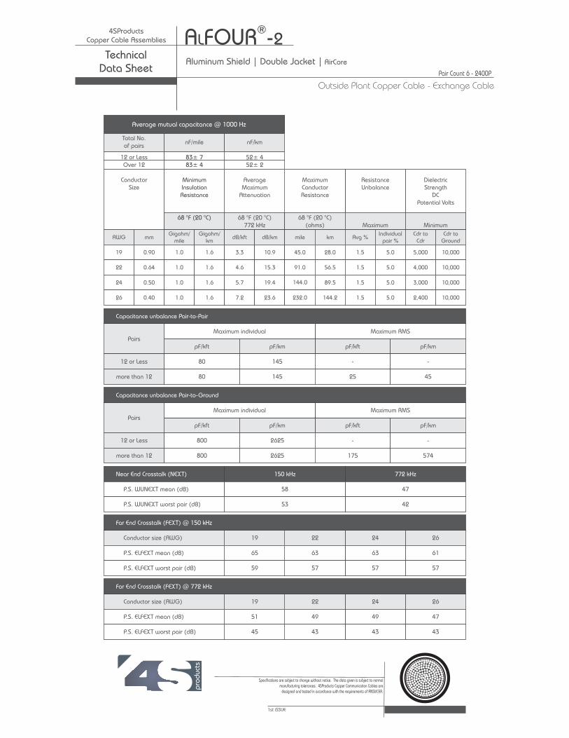
Aluminum Shield | Single Jacket | AirCore | Fig-8Technical
Data Sheet
Average mutual capacitance @ 1000 Hz
12 or LessOver 12
ConductorSize
52± 452± 2
AverageMaximum
Attenuation
68 °F (20 °C)772 kHz
MaximumConductorResistance
68 °F (20 °C)(ohms)
ResistanceUnbalance
Maximum
DielectricStrength
DCPotential Volts
Minimum
AWGGigohm/
milemm dB/kft dB/km mile km Avg %
Gigohm/km
Individualpair %
Cdr toCdr
Cdr toGround
19
22
24
26
0.90
0.64
0.50
0.40
1.0
1.0
1.0
1.0
1.6
1.6
1.6
1.6
3.3
4.6
5.7
7.2
10.9
15.3
19.4
23.6
45.0
91.0
144.0
232.0
28.0
56.5
89.5
144.2
1.5
1.5
1.5
1.5
5.0
5.0
5.0
5.0
5,000
4,000
3,000
2,400
10,000
10,000
10,000
10,000
Maximum individual Maximum RMS
pF/kft pF/km pF/kft pF/kmPairs
12 or Less
more than 12
80
80
145
145
-
25
-
45
Capacitance unbalance Pair-to-Pair
Total No.of pairs
nF/mile nF/km
Maximum individual Maximum RMS
pF/kft pF/km pF/kft pF/kmPairs
12 or Less
more than 12
800
800
2625
2625
-
175
-
574
Capacitance unbalance Pair-to-Ground
772 kHz
47
42
Near End Crosstalk (NEXT) 150 kHz
26
61
57
58
53
P.S. WUNEXT mean (dB)
P.S. WUNEXT worst pair (dB)
24
63
57
22
63
57
19
65
59
Conductor size (AWG)
P.S. ELFEXT mean (dB)
P.S. ELFEXT worst pair (dB)
Far End Crosstalk (FEXT) @ 150 kHz
26
47
43
24
49
43
22
49
43
19
51
45
Conductor size (AWG)
P.S. ELFEXT mean (dB)
P.S. ELFEXT worst pair (dB)
Far End Crosstalk (FEXT) @ 772 kHz
1st iSSUE
Specifications are subject to change without notice. The data given is subject to normalmanufacturing tolerances. 4SProducts Copper Communication Cables are
designed and tested in accordance with the requirements of ANSI/ICEA.
83± 783± 4
MinimumInsulationResistance
68 °F (20 °C)
4SProductsCopper Cable Assemblies A FOUR -8L
®
Outside Plant Copper Cable - Exchange Cable
Pair Count 6 - 2400P
Aluminum Shield | Single Jacket | AirCore | Fig-8Technical
Data Sheet

Sp
eci
fica
tions
are
sub
ject
to c
ha
ng
e w
ithout
prior
notice
. 4
SPro
duct
s ca
ble
s a
re d
esi
gned
and
test
ed
to m
eet
AN
SI/I
CEA
req
uirem
ents
.
Conductors:
Insulation:
Twisted Pairs:
Core Assembly:
Core Wrap:
Shielding:
Support Member:
Jacket:
Jacket Markings:
Solid annealed copper in 19, 22,24 and 26 AWG.
Conductors are insulated withsolid polyolefin, color coded in accordancewith industry standards.
Individual conductors aretwisted into pairs with varying lay lengths tominimize crosstalk and specific colorcombinations to provide pair identification.
Cables of 25 pairs or lessare assembled into a cylindrical core. Cableslarger than 25 pairs are assembled intounits, which are then used to assemble thecore. Units are individually identifiable bycolor coded unit binders.
A non-hygroscopic, dielectrictape is applied over the core assembly toprovide protection for the core.
A corrugated, copolymer coated,8-mil aluminum tape is applied longitudinallywith an overlap.
A 3/8 inch, 7-strand ExtraHigh Strength (EHS) galvanized steelmessenger serves as the support memberand is an integral part of the sheath. Themessenger is flooded to inhibit corrosion.
A black, linear low-densitypolyethylene jacket is applied overall. Thejacket provides a tough protective coveringdesigned to withstand exposure to directsunlight, atmospheric temperature changesand stresses expected in standardinstallations.
Information such asmanufacturer's identification, pair countAWG, product identification and a telephonehandset is printed at 2 ft. intervals on thecable jacket. Sequential footage markingsare printed at alternate 2 ft. Intervals.
Cable cut-away
Applications
4SProducts ALFOUR®-8 cables are designed for aerialinstallations. The core and support member (messenger) layparallel to each other forming a cross-sectional “Figure 8”. Themessenger is an integral part of the cable sheath, yet readilyavailable for gripping, pulling and tensioning. Installation is fastand easy using standard methods and hardware. ALFOUR®-8cables, in 19, 22, 24 and 26 AWG are capable of meeting theelectrical requirements of 100 ohms, Category 3, Backbone UTPCables as specified in TIA/EIA-568-A.
3
3
www.4SProducts.com
4621 Ponce de Leon BoulevardCoral Gables, FL 33146, USA[1] 305.666.7474[1] 305.666.7272 [email protected] e-mail
1st iSSUE
Qualifications & Approvals
Manufactured to meet requirements of ANSI/ICEA S-85-625-1996; Formerly manufactured to REA Specification PE-38, PE-38was deactivated by RUS (REA) in 1993 and is superseded bythe ANSI/ICEA specifications.
Description
4SProductsCopper Cable Assemblies A FOUR -8L 3
®
Outside Plant Copper Cable - Exchange Cable
Pair Count 6 - 400P
Aluminum Shield | Single Jacket | AirCore | Fig-8Technical
Data Sheet
3/8 in. (9.53 mm) EHS Stranded Galvanized Steel

Average mutual capacitance @ 1000 Hz
12 or LessOver 12
ConductorSize
52± 452± 2
AverageMaximum
Attenuation
68 °F (20 °C)772 kHz
MaximumConductorResistance
68 °F (20 °C)(ohms)
ResistanceUnbalance
Maximum
DielectricStrength
DCPotential Volts
Minimum
AWGGigohm/
milemm dB/kft dB/km mile km Avg %
Gigohm/km
Individualpair %
Cdr toCdr
Cdr toGround
19
22
24
26
0.90
0.64
0.50
0.40
1.0
1.0
1.0
1.0
1.6
1.6
1.6
1.6
3.3
4.6
5.7
7.2
10.9
15.3
19.4
23.6
45.0
91.0
144.0
232.0
28.0
56.5
89.5
144.2
1.5
1.5
1.5
1.5
5.0
5.0
5.0
5.0
5,000
4,000
3,000
2,400
10,000
10,000
10,000
10,000
Maximum individual Maximum RMS
pF/kft pF/km pF/kft pF/kmPairs
12 or Less
more than 12
80
80
145
145
-
25
-
45
Capacitance unbalance Pair-to-Pair
Total No.of pairs
nF/mile nF/km
Maximum individual Maximum RMS
pF/kft pF/km pF/kft pF/kmPairs
12 or Less
more than 12
800
800
2625
2625
-
175
-
574
Capacitance unbalance Pair-to-Ground
772 kHz
47
42
Near End Crosstalk (NEXT) 150 kHz
26
61
57
58
53
P.S. WUNEXT mean (dB)
P.S. WUNEXT worst pair (dB)
24
63
57
22
63
57
19
65
59
Conductor size (AWG)
P.S. ELFEXT mean (dB)
P.S. ELFEXT worst pair (dB)
Far End Crosstalk (FEXT) @ 150 kHz
26
47
43
24
49
43
22
49
43
19
51
45
Conductor size (AWG)
P.S. ELFEXT mean (dB)
P.S. ELFEXT worst pair (dB)
Far End Crosstalk (FEXT) @ 772 kHz
1st iSSUE
Specifications are subject to change without notice. The data given is subject to normalmanufacturing tolerances. 4SProducts Copper Communication Cables are
designed and tested in accordance with the requirements of ANSI/ICEA.
83± 783± 4
MinimumInsulationResistance
68 °F (20 °C)
4SProductsCopper Cable Assemblies A FOUR -8L 3
®
Outside Plant Copper Cable - Exchange Cable
Pair Count 6 - 2400P
Aluminum Shield | Single Jacket | AirCore | Fig-8Technical
Data Sheet

Sp
eci
fica
tions
are
sub
ject
to c
ha
ng
e w
ithout
prior
notice
. 4
SPro
duct
s ca
ble
s a
re d
esi
gned
and
test
ed
to m
eet
AN
SI/I
CEA
req
uirem
ents
.
Conductors:
Insulation:
Twisted Pairs:
Core Assembly:
Filling Compound:
Core Wrap:
Shielding:
Support Member:
Jacket:
Jacket Markings:
Solid annealed bare copper in 22 and 24AWG.
Conductors are insulated. The conductorinsulation is color-coded in accordance with industrystandards.
Individual conductors are twisted intopairs with varying lay lengths to minimize crosstalk andspecific color combinations to provide pair identification.
Cables of 25 pairs and less areassembled into a cylindrical core. Cables larger than 25pairs are assembled into units, which are then used toassemble the core. Units are individually identifiable bycolor-coded binders.
The core assembly is filled with an80°C ETPR or PIB base jelly compound, completely fillingthe interstices between the pairs and under the corewrap.
A non-hygroscopic, dielectric tape isapplied over the core assembly to provide protectionfor the core.
A corrugated, copolymer coated, 8-milaluminum tape is applied longitudinally with an overlap.The shield interfaces are flooded with an adhesivecompound to provide a moisture barrier and inhibitcorrosion.
A ¼ inch, 7-strand Extra HighStrength (EHS) galvanized steel messenger serves asthe support member and is an integral part of thesheath. The messenger is flooded to inhibit corrosion.
A black, linear low-density polyethylene jacketis applied overall. The jacket provides a toughprotective covering designed to withstand exposure todirect sunlight, atmospheric temperature changes andstresses expected in standard installations.
Information including themanufacturer's identification, pair count, AWG andproduct identification appears at 2-foot intervals.Sequential length markings appear at alternate 2-footintervals.
Cable cut-away
Applications
4SProducts ALFOUR®-8F cables are designed for aerialapplications where a filled cable design is preferred. The coreand support member (messenger) lay parallel to each otherforming a cross-sectional “Figure 8”. The messenger is anintegral part of the cable sheath, yet readily available forgripping, pulling and tensioning. Installation is fast and easyusing standard methods and hardware.
www.4SProducts.com
4621 Ponce de Leon BoulevardCoral Gables, FL 33146, USA[1] 305.666.7474[1] 305.666.7272 [email protected] e-mail
1st iSSUE
Qualifications & Approvals
ALFOUR-8F cables meet the physical and electricalrequirements of RUS specification 7 CFR 1755.390 (PE-39)latest issue, except that the figure-8 sheath shall meet therequirements of ANSI/ICEA S-85-625-2002, Option A.
Description
4SProductsCopper Cable Assemblies A FOURL
®-8f
Outside Plant Copper Cable - Exchange Cable
Pair Count 6 - 200P
Aluminum Shield | Single Jacket | Filled - Gel | Fig-8Technical
Data Sheet

Average mutual capacitance @ 1000 Hz
12 or LessOver 12
ConductorSize
52± 452± 2
AverageMaximum
Attenuation
68 °F (20 °C)772 kHz
MaximumConductorResistance
68 °F (20 °C)(ohms)
ResistanceUnbalance
Maximum
DielectricStrength
DCPotential Volts
Minimum
AWGGigohm/
milemm dB/kft dB/km mile km Avg %
Gigohm/km
Individualpair %
Cdr toCdr
Cdr toGround
24 0.50 1.0 1.6 5.0 16.4 144.0 89.5 1.5 5.0 4,000 15,000
Maximum individual Maximum RMS
pF/kft pF/km pF/kft pF/kmPairs
12 or Less
more than 12
80
80
145
145
-
25
-
45
Capacitance unbalance Pair-to-Pair
Total No.of pairs
nF/mile nF/km
Maximum individual Maximum RMS
pF/kft pF/km pF/kft pF/kmPairs
12 or Less
more than 12
800
800
2625
2625
-
175
-
574
Capacitance unbalance Pair-to-Ground
772 kHz
47
42
Near End Crosstalk (NEXT) 150 kHz
58
53
P.S. WUNEXT mean (dB)
P.S. WUNEXT worst pair (dB)
Conductor size (AWG)
P.S. ELFEXT mean (dB)
P.S. ELFEXT worst pair (dB)
Far End Crosstalk (FEXT) @ 150 kHz
Conductor size (AWG)
P.S. ELFEXT mean (dB)
P.S. ELFEXT worst pair (dB)
Far End Crosstalk (FEXT) @ 772 kHz
1st iSSUE
Specifications are subject to change without notice. The data given is subject to normalmanufacturing tolerances. 4SProducts Copper Communication Cables are
designed and tested in accordance with the requirements of ANSI/ICEA.
83± 783± 4
MinimumInsulationResistance
68 °F (20 °C)
4SProductsCopper Cable Assemblies A FOURL
®-8f
Outside Plant Copper Cable - Exchange Cable
Pair Count 6 - 200P
Aluminum Shield | Single Jacket | Filled - Gel | Fig-8Technical
Data Sheet
24
63
57
22
63
57
24
49
43
22
49
43
-
-
-
-
-
-
-
-
-
-
-
-
22 0.64 1.0 1.6 4.0 13.1 91.0 56.5 1.5 5.0 5,000 15,000

Sp
eci
fica
tions
are
sub
ject
to c
ha
ng
e w
ithout
prior
notice
. 4
SPro
duct
s ca
ble
s a
re d
esi
gned
and
test
ed
to m
eet
AN
SI/I
CEA
req
uirem
ents
.
Conductors:
Insulation:
Twisted Pairs:
Core Assembly:
Filling Compound:
Core Wrap:
Shielding:
Support Member:
Jacket:
Jacket Markings:
Solid annealed bare copper in 22 and 24AWG.
Conductors are dual insulated with an innerlayer of foamed, natural polyolefin covered by anouter layer of solid, colored polyolefin. The conductorinsulation is color-coded in accordance with industrystandards.
Individual conductors are twisted intopairs with varying lay lengths to minimize crosstalk andspecific color combinations to provide pairidentification.
Cables of 25 pairs and less areassembled into a cylindrical core. Cables larger than 25pairs are assembled into units, which are then used toassemble the core. Units are individually identifiable bycolor-coded binders.
The core assembly is filled with an80°C ETPR or compound, completelyfilling the interstices between the pairs and under thecore wrap.
A non-hygroscopic, dielectric tape isapplied over the core assembly to provide protectionfor the core.
A corrugated, copolymer coated, 8-milaluminum tape is applied longitudinally with anoverlap. The shield interfaces are flooded with anadhesive compound to provide a moisture barrier andinhibit corrosion.
A ¼ inch, 7-strand Extra HighStrength (EHS) galvanized steel messenger serves asthe support member and is an integral part of thesheath. The messenger is flooded to inhibit corrosion.
A black, linear low-density polyethylene jacketis applied overall. The jacket provides a toughprotective covering designed to withstand exposure todirect sunlight, atmospheric temperature changes andstresses expected in standard installations.
Information including themanufacturer's identification, pair count, AWG andproduct identification appears at 2-foot intervals.Sequential length markings appear at alternate 2-foot
PIB base jelly
Cable cut-away
Applications
4SProducts ALFOUR®-8FS cables are designed for aerialapplications where a filled cable design is preferred and/orprotection from moister is required. The core and supportmember (messenger) lay parallel to each other forming across-sectional “Figure 8”. The messenger is an integral part ofthe cable sheath, yet readily available for gripping, pulling andtensioning. Installation is fast and easy using standardmethods and hardware.
www.4SProducts.com
4621 Ponce de Leon BoulevardCoral Gables, FL 33146, USA[1] 305.666.7474[1] 305.666.7272 [email protected] e-mail
1st iSSUE
Qualifications & Approvals
ALFOUR-8FS cables meet the physical and electricalrequirements of RUS specification 7 CFR 1755.890 (PE-89)latest issue, except that the figure-8 sheath shall meet therequirements of ANSI/ICEA S-85-625-2002, Option A.
Description
4SProductsCopper Cable Assemblies
Outside Plant Copper Cable - Exchange Cable
Pair Count 6 - 200P
Aluminum Shield | Single Jacket | Filled - Foam Skin | Fig-8Technical
Data Sheet
A FOUR -8fSL®

Average mutual capacitance @ 1000 Hz
12 or LessOver 12
ConductorSize
52± 452± 2
AverageMaximum
Attenuation
68 °F (20 °C)772 kHz
MaximumConductorResistance
68 °F (20 °C)(ohms)
ResistanceUnbalance
Maximum
DielectricStrength
DCPotential Volts
Minimum
AWGGigohm/
milemm dB/kft dB/km mile km Avg %
Gigohm/km
Individualpair %
Cdr toCdr
Cdr toGround
24 0.50 1.0 1.6 5.6 18.4 144.0 89.5 1.5 5.0 3,000 10,000
Maximum individual Maximum RMS
pF/kft pF/km pF/kft pF/kmPairs
12 or Less
more than 12
80
80
145
145
-
25
-
45
Capacitance unbalance Pair-to-Pair
Total No.of pairs
nF/mile nF/km
Maximum individual Maximum RMS
pF/kft pF/km pF/kft pF/kmPairs
12 or Less
more than 12
800
800
2625
2625
-
175
-
574
Capacitance unbalance Pair-to-Ground
772 kHz
47
42
Near End Crosstalk (NEXT) 150 kHz
58
53
P.S. WUNEXT mean (dB)
P.S. WUNEXT worst pair (dB)
Conductor size (AWG)
P.S. ELFEXT mean (dB)
P.S. ELFEXT worst pair (dB)
Far End Crosstalk (FEXT) @ 150 kHz
Conductor size (AWG)
P.S. ELFEXT mean (dB)
P.S. ELFEXT worst pair (dB)
Far End Crosstalk (FEXT) @ 772 kHz
1st iSSUE
Specifications are subject to change without notice. The data given is subject to normalmanufacturing tolerances. 4SProducts Copper Communication Cables are
designed and tested in accordance with the requirements of ANSI/ICEA.
83± 783± 4
MinimumInsulationResistance
68 °F (20 °C)
24
63
57
22
63
57
24
49
43
22
49
43
-
-
-
-
-
-
-
-
-
-
-
-
22 0.64 1.0 1.6 4.5 14.8 91.0 56.5 1.5 5.0 3,600 10,000
4SProductsCopper Cable Assemblies
Outside Plant Copper Cable - Exchange Cable
Pair Count 6 - 200P
Aluminum Shield | Single Jacket | Filled - Foam Skin | Fig-8Technical
Data Sheet
A FOUR -8fSL®

Copper Cablescatalog |
Aluminum Steel Shield |
AsFOUR

Sp
eci
fica
tions
are
sub
ject
to c
ha
ng
e w
ithout
prior
notice
. 4
SPro
duct
s ca
ble
s a
re d
esi
gned
and
test
ed
to m
eet
AN
SI/I
CEA
req
uirem
ents
.
Conductors:
Insulation:
Twisted Pair
Core Assembly:
Core Wrap:
Shielding:
Outer Jacket:
Jacket Markings:
Optional Designs:
Solid annealed copper in 19, 22, 24 and 26AWG.
Conductors are insulated with solid polyolefin .The conductor insulation is color coded in accordance withindustry standard.
: Individual conductors are twisted into pairswith varying lay lengths to minimize crosstalk and specificcolor combinations to provide pair identification.
Cables of 25 pairs or less are assembledinto a cylindrical core. Cables larger than 25 pairs areassembled into units, which are then used to assemble thecore. Units are individually identifiable by color coded unitbinders.
A non-hygroscopic, dielectric tape is appliedover the core assembly to provide protection for the core.
The dual shielding system consists of two metaltapes. Inner: A corrugated, copolymer coated, 8-milaluminum tape is applied directly over the core wrap. Thealuminum tape does not butt or overlap at any point alongthe length of the cable. Outer: A corrugated, copolymercoated, 6-mil steel tape is applied directly over thealuminum and overlaps. The shield interfaces are floodedwith an adhesive compound to provide a moisture barrierand inhibit corrosion.
A black, linear low-density polyethylenejacket is applied overall. The jacket provides a toughprotective covering designed to withstand exposure todirect sunlight, atmospheric temperature changes andstresses expected in standard installations.
Information, such as manufacturer'sidentification, pair count, AWG, product identification and atelephone handset is printed at 2 ft. intervals on the cablejacket. Sequential footage markings are printed atalternate 2 ft. intervals.
AsFOUR®-2 is available with aninternal screen for use with T-Carrier systems.
Inner Jacket: A black polyethylene jacket.
Cable cut-away
Applications
4SProducts AsFOUR®- cables are designed for direct burial orduct applications where protection from moisture is required.AsFOUR®- cables are recommended for use in high-risk areaswhere additional mechanical or rodent protection is required.AsFOUR®- may be used aerially, but must be attached to asupport strand.
2
2
2
www.4SProducts.com
4621 Ponce de Leon BoulevardCoral Gables, FL 33146, USA[1] 305.666.7474[1] 305.666.7272 [email protected] e-mail
1st iSSUE
Description
4SProductsCopper Cable Assemblies
Outside Plant Copper Cable - Exchange Cable
Pair Count 6 - 3000P
Aluminum Steel Shield | Dual Jacket | AirCoreTechnical
Data Sheet
AsFOUR -®
2

1st iSSUE
Specifications are subject to change without notice. The data given is subject to normalmanufacturing tolerances. 4SProducts Copper Communication Cables are
designed and tested in accordance with the requirements of ANSI/ICEA.
4SProductsCopper Cable Assemblies
Outside Plant Copper Cable - Exchange Cable
Pair Count 6 - 3000P
Aluminum Steel Shield | Dual Jacket | AirCoreTechnical
Data Sheet
AsFOUR -®
2
19 22 24 26 0.9 0.64 0.5 0.4
nF/mile (nF/km)
? 12 pair> 12 pair
? 12 pair> 12 pair
pF/kft (pF/km)
Maximum IndividualMaximum RMS (> 12 pair)
Maximum IndividualMaximum Average (> 12 pair)
dB/kft (dB/km)
0.150 MHz:
0.772 MHz:1.600 MHz:3.150 MHz:6.300 MHz:
0.150 MHz:0.772 MHz:
1.600 MHz:3.150 MHz:6.300 MHz:
dB/kft (dB/km)
0.150 MHz:0.772 MHz:1.600 MHz:3.150 MHz:
6.300 MHz:
0.150 MHz:0.772 MHz:1.600 MHz:3.150 MHz:6.300 MHz:
dB/kft (dB/km)
(? 12 pair) 150 kHz:(> 12 pair) 150 kHz:(? 12 pair) 772 kHz:(> 12 pair) 772 kHz:
megaohm-mile (megaohm-km)
Conductor-to-ConductorConductor-to-Shield
?
65 63 63 61 (60) (58) (58) (56)
51 49 49 47 (46) (44) (44) (42)44 43 42 41 (39) (38) (37) (36)39 37 37 35 (34) (32) (32) (30)33 31 31 29 (28) (26) (26) (24)
59 57 57 57 (54) (52) (52) (52)45 43 43 43 (40) (38) (38) (38)
39 37 37 37 (34) (32) (32) (32)33 31 31 31 (28) (26) (26) (26)27 25 25 25 (22) (20) (20) (20)
1.5 2.2 3.0 4.0 (5.1) (7.3) (9.8) (13.0)1.4 2.0 2.7 3.6 (4.6) (6.6) (8.9) (11.8)3.6 5.2 6.5 8.1 (11.9) (16.9) (21.3) (26.7)3.3 4.7 5.9 7.4 (10.8) (15.4) (19.4) (24.3)
5,000 4,000 3,000 2,400 5,000 4,000 3,000 2,40020,000 20,000 20,000 20,000 20,000 20,000 20,000 20,000
19 22 24 26 0.9 0.64 0.5 0.4
/mile (? /km)Maximum Individual
Maximum AverageMaximum Individual
Mutual Capacitance
45.0 91.0 144.0 232.0 (28.0) (56.6) (89.5) (144.2)
83 ± 783 ± 4
(52 ± 4)(52 ± 2)
9492
(58)(57)
Mutual Capacitance
Average
Maximum Individual
Pair to Pair
Pair to Ground
Power Sum Mean
Maximum Average
dc Voltage for 3 seconds
Percen
Capacitance Unbalance
Far-End Crosstalk
Conductor Resistance
Resistance Unbalance
Attenuation
(145)(45)
8025
800
175
Capacitance Unbalance
Far-End Crosstalk
Conductor Resistance
Resistance Unbalance
Attenuation
t
(2,625)(574)
1000 (1600)
1.55.0
1.55.0
58 (58)
47 (47)43 (43)38 (38)34 (34)
53 (53)42 (42)
38 (38)33 (33)29 (29)
Insulation Resistance
High Voltage Test
Near-End Crosstalk
AWG mm
Conductor Size
All values at or corrected to 20°C.
ELECTRICAL
CHARACTERISTICS
Power Sum Worst Pair:
Power Sum Mean
Power Sum Worst Pair:
Insulation Resistance
High Voltage Test
Near-End Crosstalk
AWG mm
Conductor Size
All values at or corrected to 20°C.
ELECTRICAL
CHARACTERISTICS
<
<
<
<
Ohm (Ohm

Sp
eci
fica
tions
are
sub
ject
to c
ha
ng
e w
ithout
prior
notice
. 4
SPro
duct
s ca
ble
s a
re d
esi
gned
and
test
ed
to m
eet
AN
SI/I
CEA
req
uirem
ents
.
Conductors:
Insulation:
Twisted Pair
Core Assembly:
Core Wrap:
Shielding:
Outer Jacket:
Jacket Markings:
Optional Designs:
Solid annealed copper in 19, 22, 24 and 26AWG.
Conductors are insulated with solid polyolefin .The conductor insulation is color coded in accordance withindustry standard.
: Individual conductors are twisted into pairswith varying lay lengths to minimize crosstalk and specificcolor combinations to provide pair identification.
Cables of 25 pairs or less are assembledinto a cylindrical core. Cables larger than 25 pairs areassembled into units, which are then used to assemble thecore. Units are individually identifiable by color coded unitbinders.
A non-hygroscopic, dielectric tape is appliedover the core assembly to provide protection for the core.
The dual shielding system consists of two metaltapes. Inner: A corrugated, copolymer coated, 8-milaluminum tape is applied directly over the core wrap. Thealuminum tape does not butt or overlap at any point alongthe length of the cable. Outer: A corrugated, copolymercoated, 6-mil steel tape is applied directly over thealuminum and overlaps. The shield interfaces are floodedwith an adhesive compound to provide a moisture barrierand inhibit corrosion.
A black, linear low-density polyethylenejacket is applied overall. The jacket provides a toughprotective covering designed to withstand exposure todirect sunlight, atmospheric temperature changes andstresses expected in standard installations.
Information, such as manufacturer'sidentification, pair count, AWG, product identification and atelephone handset is printed at 2 ft. intervals on the cablejacket. Sequential footage markings are printed atalternate 2 ft. intervals.
AsFOUR®-2-8 is available with aninternal screen for use with T-Carrier systems.
Support Member:
Inner Jacket:
A 1/4 inch, 7-strand Extra High Strength(EHS) galvanized steel messenger serves as the supportmember and is an integral part of the sheath. Themessenger is flooded to inhibit corrosion.
A black polyethylene jacket.
Cable cut-away
Applications
4SProducts AsFOUR®-2-8 cables are designed for aerialinstallations. The core and support member (messenger) layparallel to each other forming a cross-sectional “Figure 8”. Themessenger is an integral part of the cable sheath, yet readilyavailable for gripping, pulling and tensioning. Installation isfastand easy using standard methods and hardware.
www.4SProducts.com
4621 Ponce de Leon BoulevardCoral Gables, FL 33146, USA[1] 305.666.7474[1] 305.666.7272 [email protected] e-mail
1st iSSUE
Description
4SProductsCopper Cable Assemblies
Outside Plant Copper Cable - Exchange Cable
Pair Count 6 - 400P
Aluminum Steel Shield | Dual Jacket | AirCore | Fig-8Technical
Data Sheet
AsFOUR - -®
2 8

1st iSSUE
Specifications are subject to change without notice. The data given is subject to normalmanufacturing tolerances. 4SProducts Copper Communication Cables are
designed and tested in accordance with the requirements of ANSI/ICEA.
4SProductsCopper Cable Assemblies
Outside Plant Copper Cable - Exchange Cable
Aluminum Steel Shield | Dual Jacket | AirCore | Fig-8Technical
Data Sheet
AsFOUR - -®
2 8
19 22 24 26 0.9 0.64 0.5 0.4
nF/mile (nF/km)
? 12 pair> 12 pair
? 12 pair> 12 pair
pF/kft (pF/km)
Maximum IndividualMaximum RMS (> 12 pair)
Maximum IndividualMaximum Average (> 12 pair)
dB/kft (dB/km)
0.150 MHz:
0.772 MHz:1.600 MHz:3.150 MHz:6.300 MHz:
0.150 MHz:0.772 MHz:
1.600 MHz:3.150 MHz:6.300 MHz:
dB/kft (dB/km)
0.150 MHz:0.772 MHz:1.600 MHz:3.150 MHz:
6.300 MHz:
0.150 MHz:0.772 MHz:1.600 MHz:3.150 MHz:6.300 MHz:
dB/kft (dB/km)
(? 12 pair) 150 kHz:(> 12 pair) 150 kHz:(? 12 pair) 772 kHz:(> 12 pair) 772 kHz:
megaohm-mile (megaohm-km)
Conductor-to-ConductorConductor-to-Shield
?
65 63 63 61 (60) (58) (58) (56)
51 49 49 47 (46) (44) (44) (42)44 43 42 41 (39) (38) (37) (36)39 37 37 35 (34) (32) (32) (30)33 31 31 29 (28) (26) (26) (24)
59 57 57 57 (54) (52) (52) (52)45 43 43 43 (40) (38) (38) (38)
39 37 37 37 (34) (32) (32) (32)33 31 31 31 (28) (26) (26) (26)27 25 25 25 (22) (20) (20) (20)
1.5 2.2 3.0 4.0 (5.1) (7.3) (9.8) (13.0)1.4 2.0 2.7 3.6 (4.6) (6.6) (8.9) (11.8)3.6 5.2 6.5 8.1 (11.9) (16.9) (21.3) (26.7)3.3 4.7 5.9 7.4 (10.8) (15.4) (19.4) (24.3)
5,000 4,000 3,000 2,400 5,000 4,000 3,000 2,40020,000 20,000 20,000 20,000 20,000 20,000 20,000 20,000
19 22 24 26 0.9 0.64 0.5 0.4
/mile (? /km)Maximum Individual
Maximum AverageMaximum Individual
Mutual Capacitance
45.0 91.0 144.0 232.0 (28.0) (56.6) (89.5) (144.2)
83 ± 783 ± 4
(52 ± 4)(52 ± 2)
9492
(58)(57)
Mutual Capacitance
Average
Maximum Individual
Pair to Pair
Pair to Ground
Power Sum Mean
Maximum Average
dc Voltage for 3 seconds
Percen
Capacitance Unbalance
Far-End Crosstalk
Conductor Resistance
Resistance Unbalance
Attenuation
(145)(45)
8025
800
175
Capacitance Unbalance
Far-End Crosstalk
Conductor Resistance
Resistance Unbalance
Attenuation
t
(2,625)(574)
1000 (1600)
1.55.0
1.55.0
58 (58)
47 (47)43 (43)38 (38)34 (34)
53 (53)42 (42)
38 (38)33 (33)29 (29)
Insulation Resistance
High Voltage Test
Near-End Crosstalk
AWG mm
Conductor Size
All values at or corrected to 20°C.
ELECTRICAL
CHARACTERISTICS
Power Sum Worst Pair:
Power Sum Mean
Power Sum Worst Pair:
Insulation Resistance
High Voltage Test
Near-End Crosstalk
AWG mm
Conductor Size
All values at or corrected to 20°C.
ELECTRICAL
CHARACTERISTICS
<
<
<
<
Ohm (Ohm
Pair Count 6 - 400P

Sp
eci
fica
tions
are
sub
ject
to c
ha
ng
e w
ithout
prior
notice
. 4
SPro
duct
s ca
ble
s a
re d
esi
gned
and
test
ed
to m
eet
AN
SI/I
CEA
req
uirem
ents
.
Conductors:
Insulation:
Twisted Pairs:
Core Assembly:
Filling Compound:
CORE WRAP:
SHIELDING:
Inner:
Outer:
Jacket:
Jacket Markings:
Optional Designs:
Solid annealed copper in 19, 22 and 24 AWG.
Conductors are insulated with solid polyolefin, colorcoded in accordance with industry standards.
Individual conductors are twisted into pairs withvarying lay lengths to minimize crosstalk and specific colorcombinations to provide pair identification.
Cables of 25 pairs or less are assembled intoa cylindrical core. Cables larger than 25 pairs are assembledinto units, which are then used to assemble the core. Units areindividually identifiable by color coded unit binders.
The core assembly is filled with an 80° CETPR compound, completely filling theinterstices between the pairs and under the core wrap.
A non-hygroscopic, dielectric tape is applied overthe core assembly to provide protection for the core.
The dual shielding system consists of two metaltapes.
A corrugated, copolymer coated, 8-milaluminum tape is applied directly over the corewrap. The aluminum tape does not butt or overlapat any point along the length of the cable.
A corrugated, copolymer coated, 6-mil steeltape is applied directly over the aluminum andoverlaps. The shield interfaces are flooded with anadhesive compound to provide a moisture barrierand inhibit corrosion.
A black, linear low-density polyethylene jacket isapplied overall. The jacket provides a tough protectivecovering designed to withstand exposure to direct sunlight,atmospheric temperature changes, and stresses expected instandard installations.
Information, such as manufacturer'sidentification, pair count, AWG, product identification and atelephone handset is printed at 2 ft. intervals on the cablejacket. Sequential footage markings are printed at alternate 2ft. intervals.
AsFOUR®-F is available with an internalscreen for use with T-Carrier systems. AsFOUR®-F+M is alsoavailable with mechanical protection.
or PIB base jelly
Cable cut-away
Applications
4SProducts AsFOUR®-F cables are designed for use in ductor direct burial applications where protection from moistureis required. AsFOUR®-F cables may be used aerially, butmust be attached to a support strand (messenger).AsFOUR®-F cables are recommended for use in high-riskareas where additional mechanical or rodent protection isrequired.
www.4SProducts.com
4621 Ponce de Leon BoulevardCoral Gables, FL 33146, USA[1] 305.666.7474[1] 305.666.7272 [email protected] e-mail
1st iSSUE
Qualifications & Approvals
Manufactured to meet requirements of ANSI/ICEA S-84-608-2002, RUS 7 CFR 1755.390 (PE-39).
Description
4SProductsCopper Cable Assemblies AsFOUR -f
®
Outside Plant Copper Cable - Exchange Cable
Pair Count 6 - 1200P
Aluminum Steel Shield | Single Jacket | Filled - GelTechnical
Data Sheet

Average mutual capacitance @ 1000 Hz
12 or LessOver 12
ConductorSize
52± 452± 2
AverageMaximum
Attenuation
68 °F (20 °C)772 kHz
MaximumConductorResistance
68 °F (20 °C)(ohms)
ResistanceUnbalance
Maximum
DielectricStrength
DCPotential Volts
Minimum
AWGGigohm/
milemm dB/kft dB/km mile km Avg %
Gigohm/km
Individualpair %
Cdr toCdr
Cdr toGround
19
22
24
0.90
0.64
0.50
1.0
1.0
1.0
1.6
1.6
1.6
2.8
4.0
5.0
9.2
13.1
16.4
45.0
91.0
144.0
28.0
56.5
89.5
1.5
1.5
1.5
5.0
5.0
5.0
7,000
5,000
4,000
15,000
15,000
15,000
Maximum individual Maximum RMS
pF/kft pF/km pF/kft pF/kmPairs
12 or Less
more than 12
80
80
145
145
-
25
-
45
Capacitance unbalance Pair-to-Pair
Total No.of pairs
nF/mile nF/km
Maximum individual Maximum RMS
pF/kft pF/km pF/kft pF/kmPairs
12 or Less
more than 12
800
800
2625
2625
-
175
-
574
Capacitance unbalance Pair-to-Ground
772 kHz
47
42
Near End Crosstalk (NEXT) 150 kHz
-
-
-
58
53
P.S. WUNEXT mean (dB)
P.S. WUNEXT worst pair (dB)
24
63
57
22
63
57
19
65
59
Conductor size (AWG)
P.S. ELFEXT mean (dB)
P.S. ELFEXT worst pair (dB)
Far End Crosstalk (FEXT) @ 150 kHz
-
-
-
24
49
43
22
49
43
19
51
45
Conductor size (AWG)
P.S. ELFEXT mean (dB)
P.S. ELFEXT worst pair (dB)
Far End Crosstalk (FEXT) @ 772 kHz
83± 783± 4
MinimumInsulationResistance
68 °F (20 °C)
1st iSSUE
Specifications are subject to change without notice. The data given is subject to normalmanufacturing tolerances. 4SProducts Copper Communication Cables are
designed and tested in accordance with the requirements of ANSI/ICEA.
4SProductsCopper Cable Assemblies AsFOUR -f
®
Outside Plant Copper Cable - Exchange Cable
Pair Count 6 - 1200P
Aluminum Steel Shield | Single Jacket | Filled - GelTechnical
Data Sheet

Sp
eci
fica
tions
are
sub
ject
to c
ha
ng
e w
ithout
prior
notice
. 4
SPro
duct
s ca
ble
s a
re d
esi
gned
and
test
ed
to m
eet
AN
SI/I
CEA
req
uirem
ents
.
Conductors:
Insulation:
Twisted Pair
Core Assembly:
Filling Compound:
Core Wrap:
Shielding:
Jacket:
Jacket Markings:
Optional Designs:
Solid annealed copper in 19, 22, 24 and 26AWG.
Conductors are dual insulated with an innerlayer of foamed, natural polyolefin covered by an outerlayer of solid, colored polyolefin. The conductor insulationis color coded in accordance with industry standard.
: Individual conductors are twisted into pairswith varying lay lengths to minimize crosstalk and specificcolor combinations to provide pair identification.
Cables of 25 pairs or less are assembledinto a cylindrical core. Cables larger than 25 pairs areassembled into units, which are then used to assemble thecore. Units are individually identifiable by color coded unitbinders.
The core assembly is filled with an 80° CETPR compound, completely filling theinterstices between the pairs and under the core wrap.
A non-hygroscopic, dielectric tape is appliedover the core assembly to provide protection for the core.
The dual shielding system consists of two metaltapes. Inner: A corrugated, copolymer coated, 8-milaluminum tape is applied directly over the core wrap. Thealuminum tape does not butt or overlap at any point alongthe length of the cable. Outer: A corrugated, copolymercoated, 6-mil steel tape is applied directly over thealuminum and overlaps. The shield interfaces are floodedwith an adhesive compound to provide a moisture barrierand inhibit corrosion.
A black, linear low-density polyethylene jacket isapplied overall. The jacket provides a tough protectivecovering designed to withstand exposure to direct sunlight,atmospheric temperature changes and stresses expectedin standard installations.
Information, such as manufacturer'sidentification, pair count, AWG, product identification and atelephone handset is printed at 2 ft. intervals on the cablejacket. Sequential footage markings are printed atalternate 2 ft. intervals.
AsFOUR®-FS is available with aninternal screen for use with T-Carrier systems. AsFOUR®-FS is also available with mechanical protection.
or PIB base jelly
Cable cut-away
Applications
4SProducts AsFOUR®-FS cables are designed for direct burialor duct applications where protection from moisture is required.AsFOUR®-FS cables are recommended for use in high-riskareas where additional mechanical or rodent protection isrequired. AsFOUR®-FS may be used aerially, but must beattached to a support strand.
www.4SProducts.com
4621 Ponce de Leon BoulevardCoral Gables, FL 33146, USA[1] 305.666.7474[1] 305.666.7272 [email protected] e-mail
1st iSSUE
Qualifications & Approvals
Manufactured to meet requirements of ANSI/ICEA S-84-608-2002, RUS 7 CFR 1755.890 (PE-89).
Description
4SProductsCopper Cable Assemblies
Outside Plant Copper Cable - Exchange Cable
Pair Count 6 - 3000P
Aluminum Steel Shield | Single Jacket | Filled - Foam SkinTechnical
Data Sheet
AsFOUR -fS®

1st iSSUE
Specifications are subject to change without notice. The data given is subject to normalmanufacturing tolerances. 4SProducts Copper Communication Cables are
designed and tested in accordance with the requirements of ANSI/ICEA.
4SProductsCopper Cable Assemblies
Outside Plant Copper Cable - Exchange Cable
Pair Count 6 - 3000P
Aluminum Steel Shield | Single Jacket | Filled - Foam SkinTechnical
Data Sheet
AsFOUR -fS®
Average mutual capacitance @ 1000 Hz
12 or LessOver 12
ConductorSize
52± 452± 2
AverageMaximum
Attenuation
68 °F (20 °C)772 kHz
MaximumConductorResistance
68 °F (20 °C)(ohms)
ResistanceUnbalance
Maximum
DielectricStrength
DCPotential Volts
Minimum
AWGGigohm/
milemm dB/kft dB/km mile km Avg %
Gigohm/km
Individualpair %
Cdr toCdr
Cdr toGround
19
22
24
26
0.90
0.64
0.50
0.40
1.0
1.0
1.0
1.0
1.6
1.6
1.6
1.6
3.2
4.5
5.6
7.0
10.5
14.8
18.4
23.3
45.0
91.0
144.0
232.0
28.0
56.5
89.5
144.0
1.5
1.5
1.5
1.5
5.0
5.0
5.0
5.0
4,500
3,600
3,000
2,400
10,000
10,000
10,000
10,000
Maximum individual Maximum RMS
pF/kft pF/km pF/kft pF/kmPairs
12 or Less
more than 12
80
80
145
145
-
25
-
45
Capacitance unbalance Pair-to-Pair
Total No.of pairs
nF/mile nF/km
Maximum individual Maximum RMS
pF/kft pF/km pF/kft pF/kmPairs
12 or Less
more than 12
800
800
2625
2625
-
175
-
574
Capacitance unbalance Pair-to-Ground
772 kHz
47
42
Near End Crosstalk (NEXT) 150 kHz
26
61
57
58
53
P.S. WUNEXT mean (dB)
P.S. WUNEXT worst pair (dB)
24
63
57
22
63
57
19
65
59
Conductor size (AWG)
P.S. ELFEXT mean (dB)
P.S. ELFEXT worst pair (dB)
Far End Crosstalk (FEXT) @ 150 kHz
26
47
43
24
49
43
22
49
43
19
51
45
Conductor size (AWG)
P.S. ELFEXT mean (dB)
P.S. ELFEXT worst pair (dB)
Far End Crosstalk (FEXT) @ 772 kHz
83± 783± 4
MinimumInsulationResistance
68 °F (20 °C)

Sp
eci
fica
tions
are
sub
ject
to c
ha
ng
e w
ithout
prior
notice
. 4
SPro
duct
s ca
ble
s a
re d
esi
gned
and
test
ed
to m
eet
AN
SI/I
CEA
req
uirem
ents
.
Conductors:
Insulation:
Twisted Pair
Core Assembly:
Filling Compound:
Core Wrap:
Shielding:
Outer Jacket:
Jacket Markings:
Optional Designs:
Solid annealed copper in 19, 22, 24 and 26AWG.
Conductors are dual insulated with an innerlayer of foamed, natural polyolefin covered by an outerlayer of solid, colored polyolefin. The conductor insulationis color coded in accordance with industry standard.
: Individual conductors are twisted into pairswith varying lay lengths to minimize crosstalk and specificcolor combinations to provide pair identification.
Cables of 25 pairs or less are assembledinto a cylindrical core. Cables larger than 25 pairs areassembled into units, which are then used to assemble thecore. Units are individually identifiable by color coded unitbinders.
The core assembly is filled with an 80° CETPR compound, completely filling theinterstices between the pairs and under the core wrap.
A non-hygroscopic, dielectric tape is appliedover the core assembly to provide protection for the core.
The dual shielding system consists of two metaltapes. Inner: A corrugated, copolymer coated, 8-milaluminum tape is applied directly over the core wrap. Thealuminum tape does not butt or overlap at any point alongthe length of the cable. Outer: A corrugated, copolymercoated, 6-mil steel tape is applied directly over thealuminum and overlaps. The shield interfaces are floodedwith an adhesive compound to provide a moisture barrierand inhibit corrosion.
A black, linear low-density polyethylenejacket is applied overall. The jacket provides a toughprotective covering designed to withstand exposure todirect sunlight, atmospheric temperature changes andstresses expected in standard installations.
Information, such as manufacturer'sidentification, pair count, AWG, product identification and atelephone handset is printed at 2 ft. intervals on the cablejacket. Sequential footage markings are printed atalternate 2 ft. intervals.
AsFOUR®-2FS is available with aninternal screen for use with T-Carrier systems.
or PIB base jelly
A black polyethylene jacket.Inner Jacket:
Cable cut-away
Applications
4SProducts AsFOUR®- FS cables are designed for direct burialor duct applications where protection from moisture is required.AsFOUR®- FS cables are recommended for use in high-riskareas where additional mechanical or rodent protection isrequired. AsFOUR®- FS may be used aerially, but must beattached to a support strand.
2
2
2
www.4SProducts.com
4621 Ponce de Leon BoulevardCoral Gables, FL 33146, USA[1] 305.666.7474[1] 305.666.7272 [email protected] e-mail
1st iSSUE
Qualifications & Approvals
Manufactured to meet requirements of ANSI/ICEA S-84-608-2002, RUS 7 CFR 1755.890 (PE-89).
Description
4SProductsCopper Cable Assemblies
Outside Plant Copper Cable - Exchange Cable
Pair Count 6 - 3000P
Aluminum Steel Shield | Dual Jacket | Filled - Foam SkinTechnical
Data Sheet
AsFOUR - fS®
2

1st iSSUE
Specifications are subject to change without notice. The data given is subject to normalmanufacturing tolerances. 4SProducts Copper Communication Cables are
designed and tested in accordance with the requirements of ANSI/ICEA.
4SProductsCopper Cable Assemblies
Outside Plant Copper Cable - Exchange Cable
Pair Count 6 - 3000P
Aluminum Steel Shield | Dual Jacket | Filled - Foam SkinTechnical
Data Sheet
AsFOUR - fS®
2
Average mutual capacitance @ 1000 Hz
12 or LessOver 12
ConductorSize
52± 452± 2
AverageMaximum
Attenuation
68 °F (20 °C)772 kHz
MaximumConductorResistance
68 °F (20 °C)(ohms)
ResistanceUnbalance
Maximum
DielectricStrength
DCPotential Volts
Minimum
AWGGigohm/
milemm dB/kft dB/km mile km Avg %
Gigohm/km
Individualpair %
Cdr toCdr
Cdr toGround
19
22
24
26
0.90
0.64
0.50
0.40
1.0
1.0
1.0
1.0
1.6
1.6
1.6
1.6
3.2
4.5
5.6
7.0
10.5
14.8
18.4
23.3
45.0
91.0
144.0
232.0
28.0
56.5
89.5
144.0
1.5
1.5
1.5
1.5
5.0
5.0
5.0
5.0
4,500
3,600
3,000
2,400
10,000
10,000
10,000
10,000
Maximum individual Maximum RMS
pF/kft pF/km pF/kft pF/kmPairs
12 or Less
more than 12
80
80
145
145
-
25
-
45
Capacitance unbalance Pair-to-Pair
Total No.of pairs
nF/mile nF/km
Maximum individual Maximum RMS
pF/kft pF/km pF/kft pF/kmPairs
12 or Less
more than 12
800
800
2625
2625
-
175
-
574
Capacitance unbalance Pair-to-Ground
772 kHz
47
42
Near End Crosstalk (NEXT) 150 kHz
26
61
57
58
53
P.S. WUNEXT mean (dB)
P.S. WUNEXT worst pair (dB)
24
63
57
22
63
57
19
65
59
Conductor size (AWG)
P.S. ELFEXT mean (dB)
P.S. ELFEXT worst pair (dB)
Far End Crosstalk (FEXT) @ 150 kHz
26
47
43
24
49
43
22
49
43
19
51
45
Conductor size (AWG)
P.S. ELFEXT mean (dB)
P.S. ELFEXT worst pair (dB)
Far End Crosstalk (FEXT) @ 772 kHz
83± 783± 4
MinimumInsulationResistance
68 °F (20 °C)

Copper Cablescatalog |
Copper Clad Shield
| CasFOUR

Sp
eci
fica
tions
are
sub
ject
to c
ha
ng
e w
ithout
prior
notice
. 4
SPro
duct
s ca
ble
s a
re d
esi
gned
and
test
ed
to m
eet
AN
SI/I
CEA
req
uirem
ents
.
Conductors:
Insulation:
Twisted Pairs:
Core Assembly:
Filling Compound:
Core Wrap:
Shielding:
Jacket:
Jacket Markings:
Optional Designs:
Solid annealed copper in 19, 22 and 24AWG.
Conductors are insulated with solidpolyolefin, color coded in accordance with industrystandards.
Individual conductors are twisted intopairs with varying lay lengths to minimize crosstalk andspecific color combinations to provide pair identification.
Cables of 25 pairs or less areassembled into a cylindrical core. Cables larger than 25pairs are assembled into units, which are then used toassemble the core. Units are individually identifiable bycolor coded unit binders.
The core assembly is filled with an80°C ETPR compound, completely fillingthe interstices between the pairs and under the corewrap.
A non-hygroscopic, dielectric tape is appliedover the core assembly to provide protection for thecore.
A corrugated, gopher resistant, copper alloyor copper clad steel tape is applied longitudinally withan overlap. The shield interfaces are flooded with anadhesive compound to provide a moisture barrier andinhibit corrosion.
A black, linear low-density polyethylene jacketis applied overall. The jacket provides a tough protectivecovering designed to withstand exposure to directsunlight, atmospheric temperature changes andstresses expected in standard installations.
Information, such as manufacturer'sidentification, pair count, AWG, product identificationand a telephone handset is printed at 2 ft. intervals onthe cable jacket. Sequential footage markings areprinted at alternate 2 ft. intervals.
CasFOUR®-F is available with aninternal screen for use with T-Carrier systems.CasFOUR®-F is also available with mechanicalprotection.
or PIB base jelly
Cable cut-away
Applications
4SProducts CasFOUR®-F cables are designed for use in duct ordirect burial applications where protection from moisture isrequired. CasFOUR®-F cables may be used aerially, but mustbe attached to a support strand (messenger). CasFOUR®-Fcables are recommended for use in high-risk areas whereadditional mechanical or rodent protection is required.
www.4SProducts.com
4621 Ponce de Leon BoulevardCoral Gables, FL 33146, USA[1] 305.666.7474[1] 305.666.7272 [email protected] e-mail
1st iSSUE
Qualifications & Approvals
Manufactured to meet requirements of ANSI/ICEA S-84-608-2002, RUS 7 CFR 1755.390 (PE-39).
Description
4SProductsCopper Cable Assemblies CasFOUR -f
®
Outside Plant Copper Cable - Exchange Cable
Pair Count 6 - 1800P
Copper Clad Steel Shield | Single Jacket | Filled - GelTechnical
Data Sheet

Average mutual capacitance @ 1000 Hz
12 or LessOver 12
ConductorSize
52± 452± 2
AverageMaximum
Attenuation
68 °F (20 °C)772 kHz
MaximumConductorResistance
68 °F (20 °C)(ohms)
ResistanceUnbalance
Maximum
DielectricStrength
DCPotential Volts
Minimum
AWGGigohm/
milemm dB/kft dB/km mile km Avg %
Gigohm/km
Individualpair %
Cdr toCdr
Cdr toGround
19
22
24
0.90
0.64
0.50
1.0
1.0
1.0
1.6
1.6
1.6
2.8
4.0
5.0
9.2
13.1
16.4
45.0
91.0
144.0
28.0
56.5
89.5
1.5
1.5
1.5
5.0
5.0
5.0
7,000
5,000
4,000
15,000
15,000
15,000
Maximum individual Maximum RMS
pF/kft pF/km pF/kft pF/kmPairs
12 or Less
more than 12
80
80
145
145
-
25
-
45
Capacitance unbalance Pair-to-Pair
Total No.of pairs
nF/mile nF/km
Maximum individual Maximum RMS
pF/kft pF/km pF/kft pF/kmPairs
12 or Less
more than 12
800
800
2625
2625
-
175
-
574
Capacitance unbalance Pair-to-Ground
772 kHz
47
42
Near End Crosstalk (NEXT) 150 kHz
-
-
-
58
53
P.S. WUNEXT mean (dB)
P.S. WUNEXT worst pair (dB)
24
63
57
22
63
57
19
65
59
Conductor size (AWG)
P.S. ELFEXT mean (dB)
P.S. ELFEXT worst pair (dB)
Far End Crosstalk (FEXT) @ 150 kHz
-
-
-
24
49
43
22
49
43
19
51
45
Conductor size (AWG)
P.S. ELFEXT mean (dB)
P.S. ELFEXT worst pair (dB)
Far End Crosstalk (FEXT) @ 772 kHz
83± 783± 4
MinimumInsulationResistance
68 °F (20 °C)
1st iSSUE
Specifications are subject to change without notice. The data given is subject to normalmanufacturing tolerances. 4SProducts Copper Communication Cables are
designed and tested in accordance with the requirements of ANSI/ICEA.
4SProductsCopper Cable Assemblies CasFOUR -f
®
Outside Plant Copper Cable - Exchange Cable
Pair Count 6 - 1800P
Copper Clad Steel Shield | Single Jacket | Filled - GelTechnical
Data Sheet

Sp
eci
fica
tions
are
sub
ject
to c
ha
ng
e w
ithout
prior
notice
. 4
SPro
duct
s ca
ble
s a
re d
esi
gned
and
test
ed
to m
eet
AN
SI/I
CEA
req
uirem
ents
.
Conductors:
Insulation:
Twisted Pair:
Core Assembly:
Filling Compound:
Core Wrap:
Shielding:
Jacket:
Jacket Markings:
Optional Designs:
Solid annealed copper in 19, 22, and 24AWG.
Conductors are dual insulated with an innerlayer of foamed, natural polyolefin covered by an outerlayer of solid, colored polyolefin. The conductorinsulation is color coded in accordance with industrystandards.
Individual conductors are twisted intopairs with varying lay lengths to minimize crosstalk andspecific color combinations to provide pair identification.
Cables of 25 pairs or less areassembled into a cylindrical core. Cables larger than 25pairs are assembled into units, which are then used toassemble the core. Units are individually identifiable bycolor coded unit binders.
The core assembly is filled with an80°C ETPR compound, completely fillingthe interstices between the pairs and under the corewrap.
A non-hygroscopic, dielectric tape isapplied over the core assembly to provide protectionfor the core.
A corrugated, gopher resistant, copper alloyor copper clad steel tape is applied longitudinally withan overlap. The shield interfaces are flooded with anadhesive compound to provide a moisture barrier andinhibit corrosion.
A black, linear low-density polyethylene jacketis applied overall. The jacket provides a toughprotective covering designed to withstand exposure todirect sunlight, atmospheric temperature changes andstresses expected in standard installations.
Information, such as manufacturer'sidentification, pair count AWG, product identificationand a telephone handset is printed at 2 ft. intervals onthe cable jacket. Sequential footage markings areprinted at alternate 2 ft. intervals.
CasFOUR®-FS is available with aninternal screen for use with T-Carrier systems.CasFOUR®-FS is ALSO available with mechanicalprotection.
or PIB base jelly
Cable cut-away
Applications
4SProducts CasFOUR®-FS cables are designed for direct burialor duct applications where protection from moisture is required.CasFOUR®-FS cables are recommended for use in high-riskareas where additional mechanical or rodent protection isrequired. CasFOUR®-FS cables may be used aerially, but mustbe attached to a support strand.
www.4SProducts.com
4621 Ponce de Leon BoulevardCoral Gables, FL 33146, USA[1] 305.666.7474[1] 305.666.7272 [email protected] e-mail
1st iSSUE
Qualifications & Approvals
Manufactured to meet requirements of ANSI/ICEA S-84-608-2002, RUS 7 CFR 1755.890 (PE-89).
Description
4SProductsCopper Cable Assemblies
Outside Plant Copper Cable - Exchange Cable
Pair Count 6 - 2400P
Copper Clad Steel Shield | Single Jacket | Filled - Foam SkinTechnical
Data Sheet
CasFOUR -fS®

Average mutual capacitance @ 1000 Hz
12 or LessOver 12
ConductorSize
52± 452± 2
AverageMaximum
Attenuation
68 °F (20 °C)772 kHz
MaximumConductorResistance
68 °F (20 °C)(ohms)
ResistanceUnbalance
Maximum
DielectricStrength
DCPotential Volts
Minimum
AWGGigohm/
milemm dB/kft dB/km mile km Avg %
Gigohm/km
Individualpair %
Cdr toCdr
Cdr toGround
19
22
24
0.90
0.64
0.50
1.0
1.0
1.0
1.6
1.6
1.6
3.2
4.5
5.6
10.5
14.8
18.4
45.0
91.0
144.0
28.0
56.5
89.5
1.5
1.5
1.5
5.0
5.0
5.0
4,500
3,600
3,000
10,000
10,000
10,000
Maximum individual Maximum RMS
pF/kft pF/km pF/kft pF/kmPairs
12 or Less
more than 12
80
80
145
145
-
25
-
45
Capacitance unbalance Pair-to-Pair
Total No.of pairs
nF/mile nF/km
Maximum individual Maximum RMS
pF/kft pF/km pF/kft pF/kmPairs
12 or Less
more than 12
800
800
2625
2625
-
175
-
574
Capacitance unbalance Pair-to-Ground
772 kHz
47
42
Near End Crosstalk (NEXT) 150 kHz
-
-
-
58
53
P.S. WUNEXT mean (dB)
P.S. WUNEXT worst pair (dB)
24
63
57
22
63
57
19
65
59
Conductor size (AWG)
P.S. ELFEXT mean (dB)
P.S. ELFEXT worst pair (dB)
Far End Crosstalk (FEXT) @ 150 kHz
-
-
-
24
49
43
22
49
43
19
51
45
Conductor size (AWG)
P.S. ELFEXT mean (dB)
P.S. ELFEXT worst pair (dB)
Far End Crosstalk (FEXT) @ 772 kHz
83± 783± 4
MinimumInsulationResistance
68 °F (20 °C)
1st iSSUE
Specifications are subject to change without notice. The data given is subject to normalmanufacturing tolerances. 4SProducts Copper Communication Cables are
designed and tested in accordance with the requirements of ANSI/ICEA.
4SProductsCopper Cable Assemblies
Outside Plant Copper Cable - Exchange Cable
Pair Count 6 - 2400P
Copper Clad Steel Shield | Single Jacket | Filled - Foam SkinTechnical
Data Sheet
CasFOUR -fS®

Copper Cablescatalog |
Copper Shield
| CoFOUR

Sp
eci
fica
tions
are
sub
ject
to c
ha
ng
e w
ithout
prior
notice
. 4
SPro
duct
s ca
ble
s a
re d
esi
gned
and
test
ed
to m
eet
AN
SI/I
CEA
req
uirem
ents
.
Conductors:
Insulation:
Twisted Pairs:
Core Assembly:
Filling Compound:
Core Wrap:
Shielding:
Jacket:
Jacket Markings:
Optional Designs:
Solid annealed copper in 19, 22 and 24AWG.
Conductors are insulated with solidpolyolefin, color coded in accordance with industrystandards.
Individual conductors are twisted intopairs with varying lay lengths to minimize crosstalk andspecific color combinations to provide pairidentification.
Cables of 25 pairs or less areassembled into a cylindrical core. Cables larger than 25pairs are assembled into units, which are then used toassemble the core. Units are individually identifiable bycolor coded unit binders.
The core assembly is filled with an80° C ETPR compound, completelyfilling the interstices between the pairs and under thecore wrap.
A non-hygroscopic, dielectric tape isapplied over the core assembly to provide protectionfor the core.
A corrugated, 5-mil copper tape is appliedlongitudinally with an overlap. The shield interfaces areflooded with an adhesive compound to provide amoisture barrier and inhibit corrosion.
A black, linear low-density polyethylene jacketis applied overall. The jacket provides a toughprotective covering designed to withstand exposure todirect sunlight, atmospheric temperature changes andstresses expected in standard installations.
Information, such as manufacturer'sidentification, pair count, AWG, product identificationand a telephone handset is printed at 2 ft. intervals onthe cable jacket. Sequential footage markings areprinted at alternate 2 ft. intervals.
CoFOUR®-F is available with anscreen for use with T-Carrier systems.CoFOUR®-F + M is available with mechanicalprotection.
or PIB base jelly
Cable cut-away
Applications
4SProducts CoFOUR®-F cables are designed for use in duct ordirect burial applications where protection from moisture isrequired. CoFOUR®-F cables may be used aerially, but must beattached to a support strand.
www.4SProducts.com
4621 Ponce de Leon BoulevardCoral Gables, FL 33146, USA[1] 305.666.7474[1] 305.666.7272 [email protected] e-mail
1st iSSUE
Qualifications & Approvals
Manufactured to meet requirements of ANSI/ICEA S-84-608-2002, RUS 7 CFR 1755.390 (PE-39).
Description
4SProductsCopper Cable Assemblies CoFOUR -f
®
Outside Plant Copper Cable - Exchange Cable
Pair Count 6 - 1800P
Copper Shield | Single Jacket | Filled - GelTechnical
Data Sheet

Average mutual capacitance @ 1000 Hz
12 or LessOver 12
ConductorSize
52± 452± 2
AverageMaximum
Attenuation
68 °F (20 °C)772 kHz
MaximumConductorResistance
68 °F (20 °C)(ohms)
ResistanceUnbalance
Maximum
DielectricStrength
DCPotential Volts
Minimum
AWGGigohm/
milemm dB/kft dB/km mile km Avg %
Gigohm/km
Individualpair %
Cdr toCdr
Cdr toGround
19
22
24
0.90
0.64
0.50
1.0
1.0
1.0
1.6
1.6
1.6
2.8
4.0
5.0
9.2
13.1
16.4
45.0
91.0
144.0
28.0
56.5
89.5
1.5
1.5
1.5
5.0
5.0
5.0
7,000
5,000
4,000
15,000
15,000
15,000
Maximum individual Maximum RMS
pF/kft pF/km pF/kft pF/kmPairs
12 or Less
more than 12
80
80
145
145
-
25
-
45
Capacitance unbalance Pair-to-Pair
Total No.of pairs
nF/mile nF/km
Maximum individual Maximum RMS
pF/kft pF/km pF/kft pF/kmPairs
12 or Less
more than 12
800
800
2625
2625
-
175
-
574
Capacitance unbalance Pair-to-Ground
772 kHz
47
42
Near End Crosstalk (NEXT) 150 kHz
-
-
-
58
53
P.S. WUNEXT mean (dB)
P.S. WUNEXT worst pair (dB)
24
63
57
22
63
57
19
65
59
Conductor size (AWG)
P.S. ELFEXT mean (dB)
P.S. ELFEXT worst pair (dB)
Far End Crosstalk (FEXT) @ 150 kHz
-
-
-
24
49
43
22
49
43
19
51
45
Conductor size (AWG)
P.S. ELFEXT mean (dB)
P.S. ELFEXT worst pair (dB)
Far End Crosstalk (FEXT) @ 772 kHz
83± 783± 4
MinimumInsulationResistance
68 °F (20 °C)
1st iSSUE
Specifications are subject to change without notice. The data given is subject to normalmanufacturing tolerances. 4SProducts Copper Communication Cables are
designed and tested in accordance with the requirements of ANSI/ICEA.
4SProductsCopper Cable Assemblies CoFOUR -f
®
Outside Plant Copper Cable - Exchange Cable
Pair Count 6 - 1800P
Copper Shield | Single Jacket | Filled - GelTechnical
Data Sheet

Sp
eci
fica
tions
are
sub
ject
to c
ha
ng
e w
ithout
prior
notice
. 4
SPro
duct
s ca
ble
s a
re d
esi
gned
and
test
ed
to m
eet
AN
SI/I
CEA
req
uirem
ents
.
Conductors:
Insulation:
Twisted Pairs:
Core Assembly:
Filling Compound:
Core Wrap:
Shielding:
Jacket:
Jacket Markings:
Optional Designs:
Solid annealed copper in 19, 22, and 24AWG.
Conductors are dual insulated with an innerlayer of foamed, natural polyolefin covered by anouter layer of solid, colored polyolefin. The conductorinsulation is color coded in accordance with industrystandards.
Individual conductors are twisted intopairs with varying lay lengths to minimize crosstalk andspecific color combinations to provide pairidentification.
Cables of 25 pairs or less areassembled into a cylindrical core. Cables larger than 25pairs are assembled into units, which are then used toassemble the core. Units are individually identifiable bycolor coded unit binders.
The core assembly is filled with an80°C ETPR compound, completelyfilling the interstices between the pairs and under thecore wrap.
A non-hygroscopic, dielectric tape isapplied over the core assembly to provide protectionfor the core.
A corrugated 5-mil copper tape is appliedlongitudinally with an overlap. The shield interfaces areflooded with an adhesive compound to provide amoisture barrier and inhibit corrosion.
A black, linear low-density polyethylene jacketis applied overall. The jacket provides a toughprotective covering designed to withstand exposure todirect sunlight, atmospheric temperature changes andstresses expected in standard installations.
Information, such as manufacturer'sidentification, pair count AWG, product identificationand a telephone handset is printed at 2 ft. intervals onthe cable jacket. Sequential footage markings areprinted at alternate 2 ft. intervals.
CoFOUR®-FS is available with aninternal screen for use with T-Carrier systems.CoFOUR®-FS+M is also available with mechanicalprotection.
or PIB base jelly
Cable cut-away
Applications
4SProducts CoFOUR®-FS cables are designed for direct burialor duct applications where protection from moisture is required.CoFOUR®-FS may be used aerially, but must be attached to asupport strand.
www.4SProducts.com
4621 Ponce de Leon BoulevardCoral Gables, FL 33146, USA[1] 305.666.7474[1] 305.666.7272 [email protected] e-mail
1st iSSUE
Qualifications & Approvals
Manufactured to meet requirements of ANSI/ICEA S-84-608-2002, RUS 7 CFR 1755.890 (PE-89).
Description
4SProductsCopper Cable Assemblies
Outside Plant Copper Cable - Exchange Cable
Pair Count 6 - 2400P
Copper Shield | Single Jacket | Filled - Foam SkinTechnical
Data Sheet
CoFOUR -fS®

Average mutual capacitance @ 1000 Hz
12 or LessOver 12
ConductorSize
52± 452± 2
AverageMaximum
Attenuation
68 °F (20 °C)772 kHz
MaximumConductorResistance
68 °F (20 °C)(ohms)
ResistanceUnbalance
Maximum
DielectricStrength
DCPotential Volts
Minimum
AWGGigohm/
milemm dB/kft dB/km mile km Avg %
Gigohm/km
Individualpair %
Cdr toCdr
Cdr toGround
19
22
24
0.90
0.64
0.50
1.0
1.0
1.0
1.6
1.6
1.6
3.2
4.5
5.6
10.5
14.8
18.4
45.0
91.0
144.0
28.0
56.5
89.5
1.5
1.5
1.5
5.0
5.0
5.0
4,500
3,600
3,000
10,000
10,000
10,000
Maximum individual Maximum RMS
pF/kft pF/km pF/kft pF/kmPairs
12 or Less
more than 12
80
80
145
145
-
25
-
45
Capacitance unbalance Pair-to-Pair
Total No.of pairs
nF/mile nF/km
Maximum individual Maximum RMS
pF/kft pF/km pF/kft pF/kmPairs
12 or Less
more than 12
800
800
2625
2625
-
175
-
574
Capacitance unbalance Pair-to-Ground
772 kHz
47
42
Near End Crosstalk (NEXT) 150 kHz
-
-
-
58
53
P.S. WUNEXT mean (dB)
P.S. WUNEXT worst pair (dB)
24
63
57
22
63
57
19
65
59
Conductor size (AWG)
P.S. ELFEXT mean (dB)
P.S. ELFEXT worst pair (dB)
Far End Crosstalk (FEXT) @ 150 kHz
-
-
-
24
49
43
22
49
43
19
51
45
Conductor size (AWG)
P.S. ELFEXT mean (dB)
P.S. ELFEXT worst pair (dB)
Far End Crosstalk (FEXT) @ 772 kHz
83± 783± 4
MinimumInsulationResistance
68 °F (20 °C)
1st iSSUE
Specifications are subject to change without notice. The data given is subject to normalmanufacturing tolerances. 4SProducts Copper Communication Cables are
designed and tested in accordance with the requirements of ANSI/ICEA.
4SProductsCopper Cable Assemblies
Outside Plant Copper Cable - Exchange Cable
Pair Count 6 - 2400P
Copper Shield | Single Jacket | Filled - Foam SkinTechnical
Data Sheet
CoFOUR -fS®

01
4SProductsCopper Cable Assemblies
TechnicalData Sheet
Color Code Charts - Copper Cables
02030405
0607080910
1112131415
White
Red
Black
BlueOrangeGreenBrownSlate
1617181920
2122232425
Yellow
Violet
WhiteWhiteWhiteWhite
RedRedRedRed
BlackBlackBlackBlack
BlueOrangeGreenBrownSlate
BlueOrangeGreenBrownSlate
YellowYellowYellowYellow
VioletViolet
VioletViolet
BlueOrangeGreenBrownSlate
BlueOrangeGreenBrownSlate
Pair Number Tip Color Ring Color Pair Number Tip Color Ring Color
0102030405
0607080910
1112131415
001-025
126-150
251-275
White-Blue
Red-Blue
026-050051-070076-100100-125
151-175176-200201-225226-250
276-300301-325326-350351-375
White-OrangeWhite-GreenWhite-BrownWhite-Slate
Red-GreenRed-Orange
Red-BrownRed-Slate
W-BLW-OW-GW-BRW-S
R-BLR-OR-GR-BRR-S
PairNumber Group Number Binder Color
1617181920
21222324
376-400401-425426-450451-475476-500
501-525526-550551-575576-600
Black-Blue
Black-GreenBlack-Orange
Black-BrownBlack-Slate
Yellow-Blue
Yellow-GreenYellow-Orange
Yellow-BrownYellow-Slate
Violet-Blue
Violet-GreenViolet-Orange
Violet-BrownViolet-Slate
BK-BLBK-O
-GBK-BRBK-S
Y-BLY-OY-GY-BRY-S
V-BLV-OV-GV-BRV-S
Pair Identification ColorsFor pairs numbering 1 through 25, the pair identification colors are outlined below. In cable constructions containing more than 25pairs, the colors are repeated as necessary. color coded binders are used to identify 25 pair groups of color coded pairs.
Identification of Groups of PairsFor cables through 600 pairs, 25 pair groups are identified by their binder colors in the same sequence as the pair identification isaccomplished. Group 1 has White-Blue binders, Group 2 has White-Orange binders, etc. In this manner, each pair is uniquely
identified. In cables having 25 pairs or less, binders are normally not used. However, if specified, the binders will be Group 1,White-Blue. For cables of 100-pairs or less, the use of the white binder is optional.
Page 1of 2
Specifications are subject to change without notice. 4SProducts Copper Communication Cables aredesigned and tested in accordance with the requirements of ANSI/ICEA.

4SProductsCopper Cable Assemblies
TechnicalData Sheet
Color Code Charts - Copper Cables
0001-06000601-12001201-18001801-24002401-3000
001-024 White025-048049-072073-096097-120
RedBlack
YellowViolet
WR
BKYV
Pair Number Group Number Binder Color
Super-units Binder Identification ColorsIt is desirable for manufacturing purposes to combine four 25 pair groups into “super units” whencables have 900 pairs or more.
Page 2of 2
Specifications are subject to change without notice. 4SProducts Copper Communication Cables aredesigned and tested in accordance with the requirements of ANSI/ICEA.
Spare PairsCable of 100 pairs and above may include spare pairs to replace the defective pairs (if any) during production. The number ofspare pairs shall not exceed 1% of the nominal pair size. A part of these spare pairs used for the manufacture. A part of thesespare pairs used by the manufacturer, the cable shall not include any other spare pairs for the end user.