catalog and technical manual - huliot advanced flow...
TRANSCRIPT

Soundproof Drainage Piping Systems
Catalog and Technical Manual

Vision without a task is only a dream. A task without a vision is but drudgery.But vision with a task is a dream fulfilled.
Anonymous
Dear Customers,All important pursuits begin with a vision. At Huliot, every day we focus our energies on giving practical meaning to our Corporate Vision, which we refashioned in September 2008. The company's vision appears on the wall at the entrance of all of our manufacturing plants and logistics centers. All Huliot staff, from management to production and logistics, share and embrace the same strategic vision.
Extracts from Huliot's Corporate Vision • Huliot will excel in the development and production of innovative solutions, creating added value for its customers.• Huliot will act to protect the physical environment, and to raise awareness about environmental protection.
Huliot's development of our and acoustically insulated drainage systems is an expression of our commitment to make our 'vision' a reality. Noise reduced drainage in the home is not only about environmental quality, but indeed about quality of life.
In our personal lives, we have all learned that we are capable of adapting to almost any situation, and we can learn to live with many hardships and disturbances, when faced with no choice. However, when we become aware of superior and readily available alternatives, most of us are no longer prepared to be deprived of them.
Huliot's and systems are so effective and so affordable that it makes no sense to install anything else in a new construction project. Beyond our commitment to realizing our 'vision', these product lines are also about leadership. We didn't just decide to make a better drainage system and reduce the noise of drainage flow...we decided and committed ourselves to producing the best acoustically insulated drainage system available in the world today. A challenging, yet achievable mission.
Over the past five years, we have implemented the largest investment plan in the company's 67 year history.We purchased the most sophisticated production technology available, and invested in cutting-edge mold technology. We executed a relentless and uncompromising material development program to create the highest performing material compound available for its purpose. Five years later, I am proud to declare: "MISSION ACCOMPLISHED".
Paul Steiner C.E.O. Huliot A.C.S. Ltd.
2

Index
The System Advantages .............................................................................................................................Page 4
1. Applications .....................................................................................................................................................................................................................Page 6
2. Technical Data 2.1 Materials .............................................................................................................................................................Page 7 2.2 Method of connection ..................................................................................................................................Page 7 2.3 Marking ...............................................................................................................................................................Page 7 2.4 Temperature performance ........................................................................................................................Page 8 2.5 Chemical resistance.....................................................................................................................................Page 8 2.6 Fire resistance .................................................................................................................................................Page 8 2.7 Ring stiffness ...................................................................................................................................................Page 8 2.8 Elastic modulus ..............................................................................................................................................Page 8 2.9 Elongation ..........................................................................................................................................................Page 8 2.10 Quality, Environmental, Occupational Health and Safety management .......................Page 8 2.11 Standards ........................................................................................................................................................Page 8 2.12 System approvals .......................................................................................................................................Page 8
3. Product Range Pipes............................................................................................................................Page 9 Pipes .........................................................................................................................Page 11 Bend ............................................................................................................................Page 12 Branch .......................................................................................................................Page 13 Inspection pipe, Sleeve .....................................................................................Page 16 Double socket, Long socket ...........................................................................Page 17 Reducer, End cap .................................................................................................Page 18 Bend .........................................................................................................................Page 19 Branch ....................................................................................................................Page 20 Inspection pipe ....................................................................................................Page 22 Long socket, Reducer ...................................................................................Page 23 , ULTRASEAL ..........................................................................................................Page 24 Technical Bend .......................................................................................................Page 25 WC Bend ...................................................................................................................Page 26
4. Sound Insulation 4.1 Why soundproof insulation .......................................................................................................................Page 27 4.2 Noise sources and sound levels ............................................................................................................Page 27 4.3 Considerate noise insulation in the planning phase ...................................................................Page 27 4.4 The soundproof insulation of and ........Page 29
5. Transportation, 5.1 Loading, transport and unloading .........................................................................................................Page 33 5.2 Storage and protection ................................................................................................................................Page 33 5.3 Cutting to length and assembly preparations .................................................................................Page 33 5.4 Push-fit connection method ......................................................................................................................Page 34 5.5 Mounting with clamps ..................................................................................................................................Page 34 5.6 Installation instructions ................................................................................................................................Page 35 5.7 Installing system through ceilings, floors and walls ...................Page 36 5.8 Repairs and irregular installation ...........................................................................................................Page 37 5.9 and installing in concrete .......................................................................................Page 38
6. Fire Safety 6.1 Fire behavior .....................................................................................................................................................Page 40 6.2 Fire collars .........................................................................................................................................................Page 40
7. Appendices SKZ Certificate ........................................................................................................................................................Page 41 IBS Certificate ..........................................................................................................................................................Page 42 Guarantee Declaration ........................................................................................................................................Page 43 Chemical resistance .............................................................................................................................................Page 44
Storage and Installation
3

ULTRA ring stiffness strength / ULTRA acoustic insulation - combining the
most advanced production technology with Huliot’s uniquely formulated compound.
ULTRA SILENT+
ULTRA SILENT
Measurement test results according to EN14366 (with Müpro “Yellow” clamps)
System / Flow rate 0.5 l/s 1.0 l/s 2.0 l/s 4.0 l/s
ULTRA SILENT 10 db 13 db 15 db 19 dbULTRA SILENT+ 10 db 11 db 13 db 15 db
C
95°
-20° UVEN
13501-1s2 d3
4

Depth Gauge
Easy AssemblyULTRA Easy Assembly
ULTRA Simple Handling
Depth GaugeULTRA Fit
Anti-slip ergonomic finger grips
STANDARD PIPEULTRA SILENT
69mm
S
DepthGauge
Extra Socket DepthULTRA Stable
ULTRA SolidS
54mm
Clever DesignULTRA Discharge Rate
ULTRA Smooth Flow
Swept angle
5

1. Applications:1.1. Soundproof pipes and fittings for drainage, soil and waste water discharge, low and
high temperature, made of PP-MD (Polypropylene and mineral field polypropylene compounds) in diameters Ø32-160 with push-fit connection method. Application area "BD" according to SKZ specification for test and inspection HR 3.43.
1.2. Waste water, drainage and sewerage applications1.2.1. Grey waste water - Collecting water from bathroom sinks, baths and showers and from washing machines. Applicable systems: , HT System and .
1.2.2. Waste water - Collecting waste water from toilets and kitchen sinks. Applicable systems: and HT System.
1.2.3. Rain water drainage - Collecting rain water from roofs, gutters, balconies and outdoor surfaces. Applicable systems: and HT System.
1.2.4. Sewerage - Collecting water from building waste water discharge systems to the municipal infrastructure. Applicable systems: and KG System.
1.2.5. Grey water recycling system - For garden irrigation systems and for toilet flushing systems. Applicable systems: and .
6

2. Technical data2.1. Materials: All materials comply with RoHS directive and are Halogen and Cadmium free (see appendix 2).
Triple layer pipe
Internal layer made from white PP (Polypropylene) providing the best flow performance andhigh-definition contrast for visual monitoring and control.
Middle layer made from PP-MD (Polypropylene and minerals compound) that provides the acoustic insulation.
External layer made from black PP (Polypropylene) marked with HULIOT's trademark 4 stripes - Green for the or white for the - that provides excellent UV resistant performance.
Fittings made from black PP-MD (Polypropylene and minerals compound) for outstanding acoustic insulation.
2.2. Method of connection: All products are connected by means of push-fit insertion, with single-lip high quality seals made of SBR-NR, for guaranteed sealing and leak-proof performance.
2.3. Marking:2.3.1. Pipe markings - On each pipe, the following details will be clearly printed at least once every meter, with indelible ink: Producer - HULIOT, system type, dimensions, materials, stiffness level, number of the applicable standard and category of application, date of manufacture and Standards Institute symbols.
2.3.2. Fittings markings - Every fitting will marked with all required information as follows: Producer - HULIOT, system type, dimensions, materials, stiffness level, number of the applicable standard and category of application, date of manufacture and Standards Institute symbols.
DIN standardSeries
MaterialSKZ approved
Part descriptionEN standard
7
SI StandardBarcodeHuliot logo Productiondate
Productiontime
SI Standard Description of the pipe and its application
Diameter x Wall Thickness Raw materialStiffness
EN StandardEN
Application
SKZ Certificates DIN Standard

2.4. Temperature performance:2.4.1. Hot water resistance 95°C for long term (3000 hours/50 years = 10 min/day). 98°C for short term (200 hours/50 years = 40 sec/day). 60°C for permanent load (90,000 hours/50 years = 5 hours/day).
2.4.2. Low temperature impact strength 2.4.2.1. -25°C for permanent load after assembly.
2.4.2.2. Approved by SKZ (TR 104959/13) according to DIN EN ISO 291:2008-08 for impact resistance in -20°C conditions (for transportation, assembly and short-term storage).
2.5 Chemical resistance:System materials are resistant to aggressive discharge media in the range of pH 2 to pH 12 according to DIN 8078(for chemical list - see appendix 3; page 32).
2.6 Fire resistance:2.6.1. The system tested and certified by IBS according to EN 13501-1:2009 and
classified D-s2,d2 (see appendices).2.6.2. The system meets the requirements of EN 4102-2 with fire classification B2,
smoke development category Q1 (low smoke development) and drip formation category TR1 (no drip formation).
2.7 Ring stiffness:Ring stiffness was tested according to ISO 9969 and reached the following results for dimensions Ø32-160:
pipes - SN6 (at least 6.0 kN/m²). pipes - SN12 (at least 12.0 kN/m²).
2.8 Elastic modulus:E-modulus tested according to ISO 178 and reached the results of 2300-3000 for pipes and 2600-3200 for pipes.
2.9 Elongation:Coefficient of elongation was tested and reached the results of 0.09 mm/°K for pipes and 0.05 mm/°K for pipes.
2.10 Quality, Environmental, Occupational Health and Safety management:Quality Management according to ISO 9001-2008, Environmental Management according to ISO 14001:2004 and Occupational Health and Safety Management according to OHSAS 18001:2007 approved and certified by SII.
CER
TIFIED OHS SYSTEM
THE STANDARDS INSTITUTION OF ISAREL
CERTIFIED QMS
SIISO 9001:
2000THE STANDARDS INSTITUTION OF ISAREL
CERTIFIED EMS
SIISO 14001
THE STANDARDS INSTITUTION OF ISAREL
SIOHSAS18001
CERT
IFIED OHS SYSTEM
THE STANDARDS INSTITUTION OF ISAREL
RECYCLABLEGREEN LABELISO 9001:2000ISO 14001OHSAS 18001
2.11 Standards:EN 1451-1: Polypropylene (PP) piping systems for soil and waste discharge (low and high temperature) within the building structure.EN13501-1:2009: Classification of system’s fire behavior, smoke emission, flaming and dropletsEN 4102-2: Reaction to fire tests - Ignitability of building products subjected to direct impingement of flame.EN 14366: Laboratory measurement of noise from waste water installations.
IGTD 116 Based on standards TSC 29:Huliot is licensed to mark the following products with the Green Label:• License No. 70304 for Ultra Silent products• License No. 70305 for Ultra SWG products
2.12 System approvals:SKZ mark approval certification No. A624 (see appendix 2; page 30).Fraunhofer IBP test reports P-BA 78-81/2012e (see chapter 4.5; page 23).
8

Pipes
PipesUSEM Silent
Pipe With One Socket
USDM Silent Pipe With Two
SocketsDN L D S t
pcs. pcs.
5753200015 - 32 150 45 1.8 42 20 1440
5753200025 - 32 250 45 1.8 42 20 960
5753200050 5753232050 32 500 45 1.8 42 20 480
5753200100 5753232100 32 1000 45 1.8 42 15 300
5753200150 5753232150 32 1500 45 1.8 42 15 300
5753200200 5753232200 32 2000 45 1.8 42 15 300
5753200300 5753232300 32 3000 45 1.8 42 15 300
5754000015 - 40 150 55 1.8 44 20 1440
5754000025 - 40 250 55 1.8 44 20 960
5754000050 5754040050 40 500 55 1.8 44 20 480
5754000100 5754040100 40 1000 55 1.8 44 15 420
5754000150 5754040150 40 1500 55 1.8 44 15 420
5754000200 5754040200 40 2000 55 1.8 44 15 420
5754000300 5754040300 40 3000 55 1.8 44 15 420
5755000015 - 50 150 65 1.8 46 20 960
5755000025 - 50 250 65 1.8 46 20 540
5755000050 5755050050 50 500 65 1.8 46 20 400
5755000075 - 50 750 65 1.8 46 15 270
5755000100 5755050100 50 1000 65 1.8 46 15 270
5755000150 5755050150 50 1500 65 1.8 46 15 270
5755000200 5755050200 50 2000 65 1.8 46 15 270
5755000300 5755050300 50 3000 65 1.8 46 15 270
5757500015 - 75 150 90 2.3 49 20 360
5757500025 - 75 250 90 2.3 49 20 240
5757500050 5757575050 75 500 90 2.3 49 20 160
5757500075 - 75 750 90 2.3 49 10 120
5757500100 5757575100 75 1000 90 2.3 49 10 120
5757500150 5757575150 75 1500 90 2.3 49 10 120
5757500200 5757575200 75 2000 90 2.3 49 10 120
5757500300 5757575300 75 3000 90 2.3 49 10 120
5759000015 - 90 150 107 2.8 54 16 384
5759000025 - 90 250 107 2.8 54 20 160
5759000050 5759090050 90 500 107 2.8 54 10 100
5759000100 5759090100 90 1000 107 2.8 54 10 100
5759000150 5759090150 90 1500 107 2.8 54 10 100
5759000200 5759090200 90 2000 107 2.8 54 10 100
5759000300 5759090300 90 3000 107 2.8 54 10 100
3. Product Range
9
L
t
DN
S
D
L t
DN
S
D

Pipes
PipesUSEM Silent
Pipe With One Socket
USDM Silent Pipe With Two
SocketsDN L D S t
pcs. pcs.
5751100015 - 110 150 130 3.4 65 20 180
5751100025 - 110 250 130 3.4 65 20 120
5751100050 5751111050 110 500 130 3.4 65 20 80
5751100075 - 110 750 130 3.4 65 10 80
5751100100 5751111100 110 1000 130 3.4 65 10 80
5751100150 5751111150 110 1500 130 3.4 65 10 80
5751100200 5751111200 110 2000 130 3.4 65 10 80
5751100300 5751111300 110 3000 130 3.4 65 10 80
5751200015 - 125 150 149 3.9 72 6 180
5751200025 - 125 250 149 3.9 72 6 108
5751200050 5751212050 125 500 149 3.9 72 6 48
5751200100 5751212100 125 1000 149 3.9 72 10 80
5751200150 5751212150 125 1500 149 3.9 72 10 80
5751200200 5751212200 125 2000 149 3.9 72 10 80
5751200300 5751212300 125 3000 149 3.9 72 10 80
5751600015 - 160 150 186 4.9 75 8 48
5751600025 - 160 250 186 4.9 75 8 48
5751600050 - 160 500 186 4.9 75 8 32
5751600100 - 160 1000 186 4.9 75 6 24
5751600150 - 160 1500 186 4.9 75 6 24
5751600200 - 160 2000 186 4.9 75 6 24
5751600300 - 160 3000 186 4.9 75 6 24
5742000100 - 200 1000 228 6.2 108 1 15
5742000300 - 200 3000 228 6.2 108 1 15
L
t
DN
S
D
L t
DN
S
D
10

Pipes
PipesUSEM Silent
Pipe With One Socket
USDM Silent Pipe With Two
SocketsDN L D S t
pcs. pcs.
5857500050 - 75 500 93 3.8 57 10 120
5857500075 - 75 750 93 3.8 57 10 120
5857500100 5857575100 75 1000 93 3.8 57 10 120
5857500150 - 75 1500 93 3.8 57 10 120
5857500200 5857575200 75 2000 93 3.8 57 10 120
5857500300 5857575300 75 3000 93 3.8 57 10 120
5859000050 - 90 500 109 4.5 59 10 100
5859000100 5859090100 90 1000 109 4.5 59 10 100
5859000150 - 90 1500 109 4.5 59 10 100
5859000200 5859090200 90 2000 109 4.5 59 10 100
5859000300 5859090300 90 3000 109 4.5 59 10 100
5851100050 - 110 500 132 4.8 65 10 80
5851100075 - 110 750 132 4.8 65 10 80
5851100100 5851111100 110 1000 132 4.8 65 10 80
5851100150 - 110 1500 132 4.8 65 10 80
5851100200 5851111200 110 2000 132 4.8 65 10 80
5851100300 5851111300 110 3000 132 4.8 65 10 80
5851200050 - 125 500 150 5.3 72 10 80
5851200100 5851212100 125 1000 150 5.3 72 10 80
5851200150 - 125 1500 150 5.3 72 10 80
5851200200 5851212200 125 2000 150 5.3 72 10 80
5851200300 5851212300 125 3000 150 5.3 72 10 80
5851600100 - 160 1000 191 7.5 75 6 24
5851600150 - 160 1500 191 7.5 75 6 24
5851600200 - 160 2000 191 7.5 75 6 24
5851600300 - 160 3000 191 7.5 75 6 24
11
L
t
DN
S
D
L t
DN
S
D

Bends
Bend
Code Item Description α Ø / DN L Z1 Z2
pcs. pcs.
7070000170 USB Bend
15°
32.0 44.5 4.0 9.0 40 4800
7070010170 USB Bend 40.0 51.5 4.0 10.0 40 2400
7070020170 USB Bend 50.0 56.5 5.0 11.0 40 1200
7070030170 USB Bend 75.0 63.5 7.0 14.0 20 600
7070090170 USB Bend 90.0 68.0 8.0 16.0 20 480
7070040170 USB Bend 110.0 78.0 6.0 19.0 20 240
7070050170 USB Bend 125.0 87.0 12.0 21.9 10 160
7070060170 USB Bend 160.0 99.0 8.0 22.0 5 120
7070000370 USB Bend
30°
32.0 47.5 5.0 10.0 40 4800
7070010370 USB Bend 40.0 54.5 7.0 13.0 40 2400
7070020370 USB Bend 50.0 59.5 8.0 14.0 40 1200
7070030370 USB Bend 75.0 68.5 12.0 18.0 20 600
7070090370 USB Bend 90.0 74.0 14.0 20.5 20 320
7070040370 USB Bend 110.0 85.0 16.0 25.5 20 240
7070050370 USB Bend 125.0 104 29.0 30.0 10 160
7070060370 USB Bend 160.0 105.0 27.0 29.0 5 120
7070000470 USB Bend
45°
32.0 53.0 8.0 13.0 40 4800
7070010470 USB Bend 40.0 58.5 11.0 17.0 40 2400
7070020470 USB Bend 50.0 64.0 13.0 19.0 40 1200
7070030470 USB Bend 75.0 74.5 18.0 24.0 20 600
7070090470 USB Bend 90.0 81.0 21.0 27.5 20 320
7070040470 USB Bend 110.0 94.0 25.0 33.5 20 240
7070050470 USB Bend 125.0 104.0 29.0 38.0 10 160
7070060470 USB Bend 160.0 116.0 36.0 44.0 5 120
7070080470 USB Bend 200.0 148.0 49.0 63.0 3 25
7070000670 USB Bend
67.5°
32.0 58.0 13.0 18.0 40 2400
7070010670 USB Bend 40.0 65.5 18.0 24.0 40 1600
7070020670 USB Bend 50.0 72.5 21.0 27.0 40 1200
7070030670 USB Bend 75.0 85.5 29.0 35.0 20 480
7070090670 USB Bend 90.0 94.0 34.0 40.0 20 320
7070040670 USB Bend 110.0 110.0 44.0 48.0 20 240
7070050670 USB Bend 125.0 118.0 48.0 52.0 10 160
7070000870 USB Bend
87.5°
32.0 64.0 20.0 24.0 40 2400
7070010870 USB Bend 40.0 73.5 26.0 32.0 40 1600
7070020870 USB Bend 50.0 79.5 28.5 35.0 40 1200
7070030870 USB Bend 75.0 99.5 43.0 49.0 20 480
7070090870 USB Bend 90.0 110.0 50.0 56.0 20 320
7070040870 USB Bend 110.0 129.0 60.0 66.0 20 240
7070050870 USB Bend 125.0 142.0 67.0 73.0 10 160
7070060870 USB Bend 160.0 162.0 79.5 81.0 5 120
L
α
Z1
Z2
15°
LZ1
Z2
30°
L
Z1
Z2
45°
L
Z1
Z2
67.5°
L
Z1
Z2
87.5°
DN
DN
DN
DN
DN
α
α
α
α
12

Branch
Branch
Code Item Description α DN1 DN2 Z1 Z2 Z3 L
pcs. pcs.
7070600470 USEA Branch
45°
32.0 32.0 9.0 42.0 42.0 95.0 20 1200
7070611470 USEA Branch 40.0 40.0 11.0 52.0 52.0 111.0 20 800
7070621470 USEA Branch 50.0 40.0 13.0 64.0 57.0 129.0 20 600
7070622470 USEA Branch 50.0 50.0 13.0 64.0 64.0 129.0 20 600
7070632470 USEA Branch 75.0 50.0 18.0 95.0 100.0 170.0 20 320
7070633470 USEA Branch 75.0 75.0 18.0 95.0 95.0 170.0 20 320
7070691470 USEA Branch 90.0 40.0 32.5 112.5 92.0 205.0 10 120
7070692470 USEA Branch 90.0 50.0 32.5 112.5 89.0 205.0 10 120
7070699470 USEA Branch 90.0 90.0 32.5 112.5 112.5 205.0 10 160
7070641470 USEA Branch 110.0 40.0 25.0 137.0 107.0 231.0 10 120
7070642470 USEA Branch 110.0 50.0 25.0 137.0 103.0 231.0 10 120
7070643470 USEA Branch 110.0 75.0 25.0 137.0 116.0 231.0 10 120
7070649470 USEA Branch 110.0 90.0 25.0 137.0 143.0 231.0 10 96
7070644470 USEA Branch 110.0 110.0 25.0 137.0 137.0 231.0 10 96
7070654470 USEA Branch 125.0 110.0 18.0 145.0 149.0 238.0 10 96
7070655470 USEA Branch 125.0 125.0 31.0 152.0 152.0 258.0 8 72
7070664470 USEA Branch 160.0 110.0 39.0 159.0 169.0 284.0 5 60
7070666470 USEA Branch 160.0 160.0 39.0 194.0 194.0 319.0 5 60
7070686470 USEA Branch 200.0 160.0 19.0 213.0 224.0 334.0 2 16
L
Z1
Z2
45°
Z3
DN1
DN1
DN2
α
13

Branch
Branch
87.5°
LZ1
Z2
Z3
DN1
DN1
DN2
Code Item Description α DN1 DN2 Z1 Z2 Z3 L
pcs. pcs.
7070600870 USEA Branch
87.5°
32.0 32.0 90.0 42.0 42.0 0.65 20 1280
7070611870 USEA Branch 40.0 40.0 13.0 64.0 64.0 64.5 20 800
7070621870 USEA Branch 50.0 40.0 32.3 31.0 62.0 112.5 20 600
7070622870 USEA Branch 50.0 50.0 31.0 30.0 62.0 112.5 20 600
7070632870 USEA Branch 75.0 50.0 58.0 55.0 60.0 170.0 20 320
7070633870 USEA Branch 75.0 75.0 58.0 55.0 55.0 114.5 20 320
7070692870 USEA Branch 90.0 50.0 69.0 76.0 83.0 205.0 10 120
7070642870 USEA Branch 110.0 50.0 77.0 85.0 93.0 231.0 10 120
7070666870 USEA Branch 160.0 160.0 39.0 194.0 279.0 319.0 4 48
Code Item Description
α DN1 DN2 Z1 Z2 Z3 L
pcs. pcs.
7070799870 US Swept Branch
87.5°
90.0 90.0 79.0 66.0 97.0 205.0 10 160
7070743870 US Swept Branch 110.0 75.0 82.0 60.0 97.0 211 10 120
7070749870 US Swept Branch 110.0 90.0 82.0 60.0 97.0 211.0 10 120
7070744870 US Swept Branch 110.0 110.0 82.0 60.0 97.0 211.0 10 120
7070754870 US Swept Branch 125.0 110.0 100.0 65.0 117.0 240 6 72
7070764870 US Swept Branch 160.0 110.0 96.0 84.0 117.0 266 4 48
LZ1
Z2
Z3
DN1
DN2
87.5°DN1
α
α
14

Code Item Description α DN1 DN2 Z1 Z2 Z3 L
pcs. pcs.
7071244870 US Corner Branch87.5°
110.0 110.0 62.0 70.0 69.0 198.0 5 72
7071254870 US Corner Branch 125.0 110.0 62.0 64.0 69.0 202.0 5 60
Code Item Description α DN1 DN2 Z1 Z2 Z3 L
pcs. pcs.
7071042670 USDA Double Branch 67.5°
110.0 50.0 17.0 73.0 54.0 207.0 10 120
7071044670 USDA Double Branch 110.0 110.0 51.0 85.0 85.0 272.0 6 72
Branch
Branch
Double Branch
DN1
DN1
DN2
L
DN2
Z2
Z1
Z3
α
L
DN1
DN2DN2
DN1
αZ3
Z2
Z1
15

Branch
Inspection Pipe
Code Item Description Ø / DN Ø / DN2 t L L1
pcs. pcs.
7079120070 USRE Inspection Pipe 50.0 45.0 55.0 140.0 65.0 20 800
7079130070 USRE Inspection Pipe 75.0 45.0 71.0 140.0 98.0 20 800
7079190070 USRE Inspection Pipe 90.0 45.0 60.5 202.0 118.0 10 240
7079140070 USRE Inspection Pipe 110.0 97.0 64.0 231.0 142.0 10 120
7079150070 USRE Inspection Pipe 125.0 97.0 73.0 222.0 158.0 10 120
7079160070 USRE Inspection Pipe 160.0 97.0 84.0 236.0 192.0 5 60
7079180070 USRE Inspection Pipe 200.0 97.0 93.0 343.0 231.0 2 24
Code Item Description Ø / DN t L
pcs. pcs.
7071710070 USU Sleeve 40.0 14.0 60.0 30 1440
7071720070 USU Sleeve 50.0 14.0 68.0 20 1200
7071730070 USU Sleeve 75.0 14.0 77.0 20 800
7071790070 USU Sleeve 90.0 14.0 85.0 20 480
7071740070 USU Sleeve 110.0 17.0 97.0 20 320
7071750070 USU Sleeve 125.0 16.8 118.6 10 240
7071760070 USU Sleeve 160.0 17.0 131.0 10 180DN
t
t
L
Sleeve
Sleeve
L
L1
t
DN
DN2
DN
16

Code Item Description Ø / DN t L Z
pcs. pcs.
7071700270 USMM Double Socket 32.0 14.0 64.0 2.0 30 1800
7071710270 USMM Double Socket 40.0 14.0 60.0 2.0 30 1440
7071720270 USMM Double Socket 50.0 14.0 68.0 2.0 20 1200
7071730270 USMM Double Socket 75.0 14.0 77.0 2.3 20 800
7071790270 USMM Double Socket 90.0 14.0 85.0 1.4 20 480
7071740270 USMM Double Socket 110.0 17.0 97.0 3.3 20 320
7071750270 USMM Double Socket 125.0 16.8 118.6 4.1 10 240
7071760270 USMM Double Socket 160.0 17.0 131.0 4.5 10 180
DN
t
t
L Z
Double Socket
Double Socket
Long Socket
Long Socket
Code Itemdescription Ø/DN t1 t2 L Z
pcs. pcs.
7072210070 USTL Long Socket 40.0 13.1 107.0 66.0 13.0 30 1800
7072220070 USTL Long Socket 50.0 13.1 99.0 61.0 7.0 20 1200
7072230070 USTL Long Socket 75.0 13.1 113.0 69.0 10.0 20 360
7072290070 USTL Long Socket 90.0 13.1 131.0 76.0 13.0 20 320
7072240070 USTL Long Socket 110.0 16.0 141.0 87.0 14.0 20 240
7072250070 USTL Long Socket 125.0 19.1 189.0 91.0 16.0 10 160
7072260070 USTL Long Socket 160.0 23.1 107.0 160.0 20.5 5 80
DNt1
t2
LZ
DN
17

Code Item Description Ø / DN L
pcs. pcs.
7071610070 USM End Cap 40.0 40.0 40 4800
7071620070 USM End Cap 50.0 44.0 30 3600
7071630070 USM End Cap 75.0 51.0 20 2400
7071690070 USM End Cap 90.0 60.0 20 1600
7071640070 USM End Cap 110.0 62.0 20 800
7071650070 USM End Cap 125.0 75.0 10 480
7071660070 USM End Cap 160.0 86.0 10 320
End Cap
End Cap
Internal
Code Item Description DN1 DN2 L t Z
pcs. pcs.
7072110070 USR Reducer 40.0 32.0 48.0 42.0 14.0 30 3600
7072120070 USR Reducer 50.0 32.0 65.0 42.0 15.0 30 3600
7072121070 USR Reducer 50.0 40.0 64.0 42.0 15.0 30 1800
7072191070 USR Reducer 90.0 40.0 93.0 47.0 35.0 20 800
7072132070 USR Reducer 75.0 50.0 85.0 47.0 26.0 20 800
7072192070 USR Reducer 90.0 50.0 97.0 47.0 34.0 20 800
7072142070 USR Reducer 110.0 50.0 118.0 47.0 46.0 20 480
7072147070 USR Reducer 110.0 63.0 107.0 52.0 39.0 20 360
7072143070 USR Reducer 110.0 75.0 106.0 52.0 34.0 20 360
7072149070 USR Reducer 110.0 90.0 101.0 55.0 29.0 20 360
7072154070 USR Reducer 125.0 110.0 106.0 64.0 29.0 10 240
7072164070 USR Reducer 160.0 110.0 137.0 64.0 84.0 10 160
7072165070 USR Reducer 160.0 125.0 140.0 55.0 74.0 10 80
7072186070 USR Reducer 200.0 160.0 153.0 80.0 54.0 6 96
Reducer
Reducer
t
L
Z
DN2
DN1
DN
L
18

Bend
ULTRA SILENT+ Bend
15°
30°
45°
87.5°
L
α
Z1
Z2
DN
L
α
Z1
Z2
DN
L
α
Z1
Z2
DN
L
α
Z1
Z2
DN
Code Item Description α Ø / DN L Z1 Z2
pcs. pcs.
7870040170 USPB Bend 15° 110 78 6 19 20 240
7870040370 USPB Bend 30° 110 85 16 25.5 20 240
7870040470 USPB Bend
45°
110 94 25 33.5 20 240
7870050470 USPB Bend 125 104 29 38 10 160
7870060470 USPB Bend 160 116 36 44 5 120
7870040870 USPB Bend 87.5° 110 129 60 66 20 240
19

Branch
ULTRA SILENT+ Branch
Code Item Description α DN1 DN2 Z1 Z2 Z3 L
pcs. pcs.
7870642470 USPEA Branch
45°
110 50 25 137 103 231 10 120
7870644470 USPEA Branch 110 110 25 137 137 231 10 96
7870654470 USPEA Branch 125 110 18 145 149 238 10 96
LZ1
Z2
Z3
DN1
DN1
DN2
α
Code Item Description α DN1 DN2 Z1 Z2 Z3 L
pcs. pcs.
7870642870 USPEA Branch 87.5° 110 50 77 85 60 231 10 120
L
Z1
Z2
45°
Z3
DN1
DN1
DN2
α
20

Branch
ULTRA SILENT+ Branch
LZ1
Z2
Z3
DN1
DN2
DN1
α
Code Item Description α DN1 DN2 Z1 Z2 Z3 L
pcs. pcs.
7870744870 USPEA Swept Branch
87.5°
110 110 82 60 97 211 10 120
7870754870 USPEA Swept Branch 125 110 100 65 117 240 6 72
7870764870 USPEA Swept Branch 160 110 96 84 117 266 4 48
DN1
DN1
DN2
L
DN3
Z2
Z1
Z3
α
Code Item Description α DN1 DN2 Z1 Z2 Z3 L d3
pcs. pcs.
7871244870 USP Corner Branch87.5°
110 110 62 70 69 198 110 5 72
7871254870 USP Corner Branch 125 110 62 64 69 202 110 5 60
21

Branch
ULTRA SILENT+ Inspection Pipe
L
L1
t
DN1
DN2
DN1
Code Item Description DN1 DN2 t L L1
pcs. pcs.
7879140070 USRE Inspection Pipe 110 97 64 231 142 10 120
7879150070 USRE Inspection Pipe 125 97 73 222 158 10 120
7879160070 USRE Inspection Pipe 160 97 84 236 192 5 60
DNt1
t2
LZ
DN
Long Socket
ULTRA SILENT+ Long Socket
Code Item Description DN t1 t2 L Z
pcs. pcs.
7872240070 USTL Long Socket 110 16 141 87 14 20 240
22

t
L
Z
DN2
DN1
Reducer
ULTRA SILENT+ Reducer
Code Item Description DN1 DN2 L t Z
pcs. pcs.
7872154070 USR Reducer 125 110 106 64 29 10 240
7872164070 USR Reducer 160 110 137 64 84 10 160
23

Lubricant
LOCKSEAL™
Code Item Description DN1 DN2 L
pcs. pcs.
7072330000 US Ø75 91.5 79.8 81.0 40 960
7072340000 US Ø110 130.0 115.5 85.0 30 480
7072350000 US Ø125 149.0 132.4 105.0 12 480
7072360000 US Ø160 186.0 165.4 118.0 10 192DN1
DN2
L
ULTRASEAL™
ULTRASEAL
Code Item Description DN1 DN2 L A S L1
pcs. pcs.
7981100000 Ultra Seal 110 220 102 340 340 3 52 5 30
7981250000 Ultra Seal 125 239 121 500 500 3 52 5 20
7981600000 Ultra Seal 160 266 149 500 500 3 52 5 20
L
DN 1DN 2
L1
S
L
Code Item Description
pcs. pcs.
47700012 Ultra- Lubricant For Plastic Pipes 250 ml 50 -
47700013 Ultra- Lubricant For Plastic Pipes 1000 ml 12 1728
24

Technical Bend
Technical Bend
Code Item Description DN1 DN2 L1 L2
pcs. pcs.
7074010970 USSW Technical Bend 32.0 46.0 76.0 58.0 20 2400
7074021970 USSW Technical Bend 40.0 50.0 82.0 56.0 20 1200
7074011970 USSW Technical Bend 40.0 46.0 76.0 56.0 20 2400
7074022970 USSW Technical Bend 50.0 50.0 82.0 60.0 20 1200
DN1
L
L2
DN2
Code Item Description DN1 DN2 L1 L2
pcs. pcs.
7074021971 USSWL Long Technical bend Ø40/50 40.0 50.0 140.0 56.0 20 1200
7074011971 USSWL Long Technical bend Ø40/46 40.0 46.0 140.0 57.0 20 1200
DN1
L
L2
DN2
25

WC Bend
WC Bend
Code Item Description DN1 DN2 L1 L2
pcs. pcs.
7195000070 USSBL Long WC Bend 119.6 90.0 175.0 225.0 10 120
7155000070 USSBL Long WC Bend 119.6 110.0 185.0 226.0 10 120
Code Item Description DN1 DN2 L1 L2 Z L3 L4 D3 D4
pcs. pcs.
7154040490 USSBL WC Bend Ø110+Double Ø40/45° 90.0 40.0 225.0 185.0 60.0 250.9 50.9 50.1 41.1 8 96
7155050490 USSBL WC Bend Ø110+Double Ø50/45° 110.0 50.0 225.0 185.0 60.0 264.0 50.9 60.1 51.1 8 96
L2
DN1
L1
DN2
L3
L4
D3
D4
L2
DN1
L1
DN2
26

4. Sound Insulation4.1. Why soundproof insulation:
The human aspiration to improve quality of life has led to the treatment all types of pollution, most of which are created by humanity itself. Noise is a treatable pollution in almost every living environment, particularly noise generated by humankind.Disruptive noises in buildings have triggered the pursuit of the minimization of that noise pollution. People should be protected from disturbing airborne and structure-borne sound. Architectural sound protection measures are most relevant in buildings where people spend relatively long time periods (e.g. residences, offices, etc). Disturbing noise is mainly caused by sources within the construction itself (structure-borne noise), generally deriving from building engineering systems, that either directly or indirectly give rise to noise.
4.2. Noise sources and sound levels: DIN 4109: Sound insulation in buildings, specifies the requirements for the sound insulation of rooms requiring protection against noise and the permissible noise levels in rooms requiring protection against noise in residential and non-residential buildings. Compliance with these requirements is necessary in order to achieve the stated noise protection goals. The requirements of DIN 4109 apply to the protection against noise emanating from other rooms (e.g. neighboring apartments) which arises during normal use, noise emanating from building services and from commercial and industrial businesses in the same building or in structurally connected buildings, outdoor noise, e.g. traffic noise and noise from commercial and industrial businesses that are not structurally connected with rooms requiring noise protection (see table 4.2.1). The requirements form the basis for the design of new buildings and alterations to existing ones. The standard only applies to refurbishment work if the noise protection measures are technically feasible.
4.2.1.
4.3. Consideration of noise insulation in the planning phase: For the best acoustic insulation, several topics must be considered during the planning phase of building construction and the waste water system:
4.3.1. The location and orientation of the building.
4.3.2. The design of the residence, the location and orientation of the rooms, particularly in multi-floor buildings.
4.3.3. Construction materials: walls, partitions, ceiling, doors and windows, etc. with attention to the acoustic insulation performances of each material.
Table of sound levels L (loudness) andcorresponding sound pressure and sound intensity
Sound Sources (Noise)Examples with distance
Sound PressureLevel LP dB SPL
Sound PressureW/m2
Sound energy quantity
Jet aircraft, 50 m away 140 100
Chainsaw, 1 m distance 110 0.1
Disco, 1 m from speaker 100 0.01
Kerbside of busy road, 5 m 80 0.0001
Vacuum cleaner, distance 1 m 70 0.00001
Average home 50 0.0000001
Quiet library 40 0.00000001
Quiet bedroom at night 30 0.000000001
system 17
system 13
Rustling leaves in the distance 10 0.00000000001
Threshold of hearing 0 0.0000000000001
27
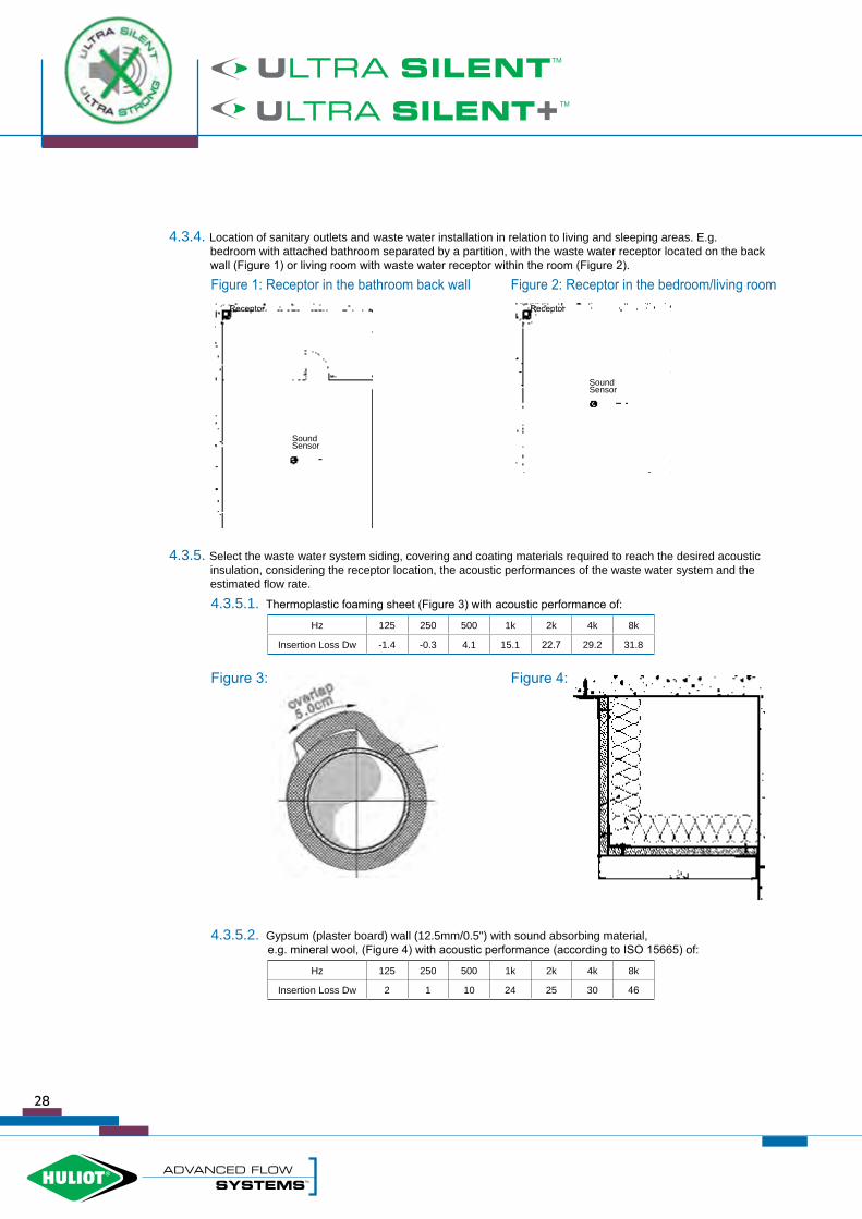
4.3.4. Location of sanitary outlets and waste water installation in relation to living and sleeping areas. E.g. bedroom with attached bathroom separated by a partition, with the waste water receptor located on the back wall (Figure 1) or living room with waste water receptor within the room (Figure 2).
Figure 1: Receptor in the bathroom back wall Figure 2: Receptor in the bedroom/living room
4.3.5. Select the waste water system siding, covering and coating materials required to reach the desired acoustic insulation, considering the receptor location, the acoustic performances of the waste water system and the estimated flow rate.
4.3.5.1. Thermoplastic foaming sheet (Figure 3) with acoustic performance of:
8k4k2k1k500250125Hz
31.829.222.715.14.1-0.3-1.4Insertion Loss Dw
Figure 3: Figure 4:
4.3.5.2. Gypsum (plaster board) wall (12.5mm/0.5") with sound absorbing material,e.g. mineral wool, (Figure 4) with acoustic performance (according to ISO 15665) of:
8k4k2k1k500250125Hz
463025241012Insertion Loss Dw
SoundSensor
SoundSensor
ReceptorReceptor
28

4.3.5.3. Combination of gypsum wall (12.5mm/0.5") with sound absorbing material (e.g. mineral wool) and thermoplastic foaming sheet (Figure 5) with acoustic performance (according to ISO 15665) of:
8k4k2k1k500250125Hz
77.859.247.739.114.10.70.6Insertion Loss Dw
Figure 5:
4.4. The soundproof insulation of and The system's acoustic performance was tested at the Fraunhofer Laboratory (Germany) in accordance with the DIN 4109 and the EN 14366 standards (see 4.4.1-3). Accordingly, several scenarios were tested and calculated (according to ISO 15665 and ISO 10140-2) (see 4.4.4-5).
4.4.1. The pipe system assembly which was tested at the Fraunhofer Laboratory is represented in figure 6 with pipes and fittings with diameter of 110mm, with pipe clamps of several types
(e.g. Müpro DAMMGLUST yellow, Bismat 2000 etc).
Figure 6:
29

4.4.2. The results of the Ultra Silent™ pipe system's noise reduction performance at various continuous water flow rates (0.5 l/s, 1.0 l/s, 2.0 l/s and 4.0 l/s) are detailed in the table below. The different measures represent readings taken of the sound level measured in the basement test room UG at the front and rear of the wall (according to standard EN ISO/IEC 17025); the airborne sound pressure and the characteristic structure-borne sound levels measured (according DIN EN 14366), as follows:
With Müpro DAMMGLUST
Yellow clampsTR; P-BA 78/2012e
Flow rate [l/s] 0.5 1.0 2.0 4.0
UG front sound level [dB(A)] (EN ISO/IEC 17025) 48 52 54 56
UG rear sound level [dB(A)] (EN ISO/IEC 17025) 13 16 18 21
Airborne sound pressure level [dB(A)] (DIN EN 14366) 48 52 54 56
Structure borne sound level [dB(A)] (DIN EN 14366) 10 13 15 19
With BISMAT 2000 clampsTR; P-BA 77/2012e
UG front sound level [dB(A)] (EN ISO/IEC 17025) 48 51 54 55
UG rear sound level [dB(A)] (EN ISO/IEC 17025) 13 16 19 23
Airborne sound pressure level [dB(A)] (DIN EN 14366) 48 51 54 55
Structure borne sound level [dB(A)] (DIN EN 14366) 10 13 17 21
With Müpro DAMMGLUSTYellow clamps
TR; P-BA 79/2012e
UG front sound level [dB(A)] (EN ISO/IEC 17025) 46 48 50 53
UG rear sound level [dB(A)] (EN ISO/IEC 17025) 10 13 15 18
Airborne sound pressure level [dB(A)] (DIN EN 14366) 46 48 50 53
Structure borne sound level [dB(A)] (DIN EN 14366) <10 11 13 15
With BISMAT 2000 clampsTR; P-BA 80/2012e
UG front sound level [dB(A)] (EN ISO/IEC 17025) 42 47 49 52
UG rear sound level [dB(A)] (EN ISO/IEC 17025) <10 13 18 20
Airborne sound pressure level [dB(A)] (DIN EN 14366) 42 47 49 52
Structure borne sound level [dB(A)] (DIN EN 14366) <10 11 15 18
30

4.4.3. The Fraunhofer test reports:
4.4.4. The first scenario is based on:
4.4.4.1. Bedroom area of 12m² including 4m² bathroom with partition and door, with the waste water receptor located at the bathroom's far corner, as appears in chapter 4.3.4 Figure 1.
4.4.4.2. Huliot Ø110 receptor with 2 l/s water flow rate.
4.4.4.3. The receptor is covered with gypsum wallboard (12.5mm/0.5") lined with sound absorbing material (e.g. mineral wool) as appears in chapter 4.3.5.2, Figure 4.
4.4.4.4. The calculated sound measurement results appear in the table below:
[Hz] Noise measuredon the pipe [dB(A)]
Noise reduction by the gypsum cover
Noise reductionby the door
100 19 1.8 26.5
125 20.5 1.7 17.5
160 22 2.1 18.3
200 22.5 0.8 14.5
250 25 0.7 15.9
315 27.5 0.1 12.7
400 34 6.3 15.0
500 35.5 13 16.4
630 37 14.3 16.6
800 37.5 24.2 15.9
1000 37.5 23 16.1
1250 37 25 15.7
1600 39.5 23.5 16.9
2000 42 26.1 15.5
2500 44 27 12.4
3150 45 26.5 10.7
4000 46.5 31 11.6
5000 48 39.4 13.6
4.4.4.5. The sound level measured [dB (A)] is LAF max = 19.4 dB31

4.4.5. The second scenario is based on:
4.4.5.1. Bedroom area of 12m², with the waste water receptor located at the corner of the room as appears inchapter 4.3.4 Figure 2.
4.4.5.2. Huliot Ø110 receptor with 2 l/s water flow rate.
4.4.5.3. The receptor is covered with a combination of gypsum wallboard (12.5mm/0.5") lined with sound absorbing material (e.g. mineral wool) and thermoplastic foaming sheet, as appears in chapter 4.3.5.3 Figure 5.
4.4.5.4. The calculated sound measurement results appear in the table below:
[Hz] Noise measuredon the pipe [dB(A)]
Noise reduction by the gypsum cover
Noise reductionby the door
100 19 -0.21 0.48
125 20.5 -0.99 3.23
160 22 -2.69 4.46
200 22.5 -1.16 5.26
250 25 -0.12 5.64
315 27.5 0.42 6.73
400 34 1.56 6.24
500 35.5 4.53 5.21
630 37 9.60 5.85
800 37.5 12.49 6.60
1000 37.5 16.19 6.54
1250 37 18.68 6.93
1600 39.5 20.88 6.29
2000 42 23.07 6.24
2500 44 25.19 7.21
3150 45 28.27 7.28
4000 46.5 28.95 7.21
5000 48 30.66 7.21
4.4.5.5. The sound level measured [dB (A)] is LAF max = 27.2 dB
32
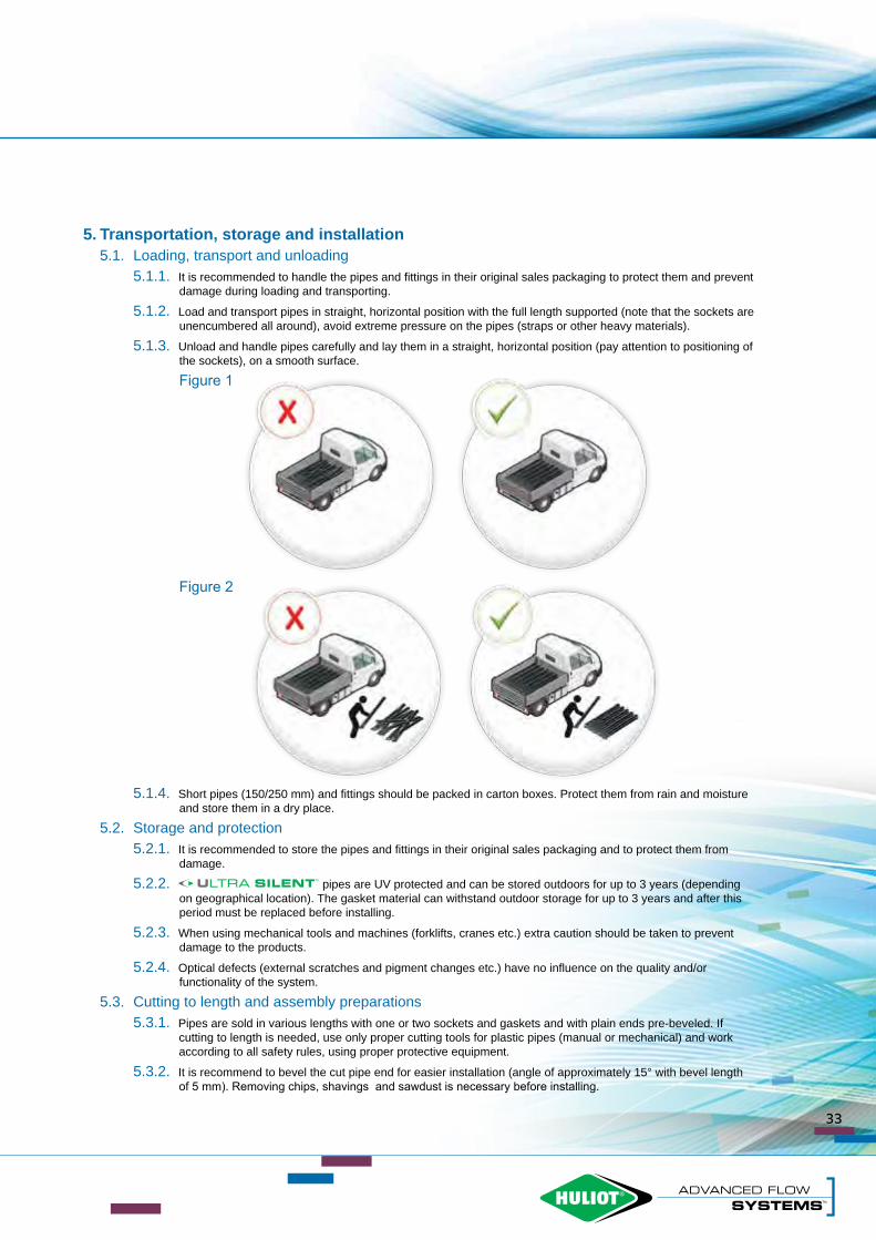
5. Transportation, storage and installation5.1. Loading, transport and unloading
5.1.1. It is recommended to handle the pipes and fittings in their original sales packaging to protect them and prevent damage during loading and transporting.
5.1.2. Load and transport pipes in straight, horizontal position with the full length supported (note that the sockets are unencumbered all around), avoid extreme pressure on the pipes (straps or other heavy materials).
5.1.3. Unload and handle pipes carefully and lay them in a straight, horizontal position (pay attention to positioning of the sockets), on a smooth surface.
Figure 1
Figure 2
5.1.4. Short pipes (150/250 mm) and fittings should be packed in carton boxes. Protect them from rain and moisture and store them in a dry place.
5.2. Storage and protection5.2.1. It is recommended to store the pipes and fittings in their original sales packaging and to protect them from damage.
5.2.2. pipes are UV protected and can be stored outdoors for up to 3 years (depending on geographical location). The gasket material can withstand outdoor storage for up to 3 years and after this period must be replaced before installing.
5.2.3. When using mechanical tools and machines (forklifts, cranes etc.) extra caution should be taken to prevent damage to the products.
5.2.4. Optical defects (external scratches and pigment changes etc.) have no influence on the quality and/or functionality of the system.
5.3. Cutting to length and assembly preparations5.3.1. Pipes are sold in various lengths with one or two sockets and gaskets and with plain ends pre-beveled. If cutting to length is needed, use only proper cutting tools for plastic pipes (manual or mechanical) and work according to all safety rules, using proper protective equipment.
5.3.2. It is recommend to bevel the cut pipe end for easier installation (angle of approximately 15° with bevel length of 5 mm). Removing chips, shavings and sawdust is necessary before installing.
33

A A
10
5.4. Push-fit connection method5.4.1. Check the position and integrity of the lip seal in the socket gasket slot. Clean the seal and the socket.
5.4.2. Clean the plain pipe end from sawdust and scraps - it's recommended to apply a thin layer of lubricant around the plain pipe end.
5.4.3. Push the plain end into the socket while slightly turning until the end of the socket sleeve, then pull the pipe back approximately 10 mm (Figure 1).
Figure 1 Figure 2
5.5. Mounting with clamps5.5.1. For mounting system, use steel brackets with rubber inserts approved for acoustic insulation systems.
5.5.2. Where pipes are installed vertically, every pipe must be fastened with brackets directly under the socket, to prevent pipe movement (Figure 2).
5.5.3. Maximum distances between the brackets for horizontal and vertical installation, as below. (See table and Figure 3):
Pipe DN(external diameter)
Max. bracket distance for horizontal installation - D1 max
Max. bracket distance for vertical installation - D max
Ø 50 0.80 1.50
Ø 75 1.10 2.00
Ø 90 1.40 2.00
Ø 110 2.00 2.00
Ø 125 2.00 2.00
Ø 160 2.40 2.00
D1 max D max
Figure 3
34

5.6. Installation instructions5.6.1. For vertical wall mounting, 2 brackets will be assembled on every floor, taking into account the specified maximum distance between brackets as per table in 5.5.3.
5.6.2. Fixed bracket: The first of the two brackets on each floor should be installed in the lower third of the floor height, just below the pipe or fitting socket, and must be tightened according to the instructions in 5.6.4, below.
5.6.3. Sliding bracket: The second of the two brackets should be mounted in the upper third of the floor height, with the bracket rubber only lightly touching the pipe to enable linear expansion of the pipe system (Figure 4).
Figure 4
5.6.4. Bracket tightening: In order to prevent structure-borne noise transmission, use only recommended brackets with proper dimensions and leave space of 5 mm in the bracket aperture when screwing closed (Figures 5-6).
Figure 5 - Incorrect tightening: Figure 6 - Correct tightening:
5 mm
Sliding bracket - mount in the upper third of the floor height, with the bracket rubber only lightly touching the pipe.
Fixed bracket - mount in the lower third of the floor height, just below the socket, and tighten according to the instructions.
35

5.7. Installing system through ceilings, floors and walls5.7.1. It is important in acoustic insulated systems to avoid contact between system components and rigid elements, such as walls, ceilings, floors etc., in order to prevent structure-borne noise transmission.
5.7.2. For pipes traversing walls and ceilings, a space of at least 30 mm should be maintained between the pipe and any rigid material.
5.7.3. If the spaces around the pipes traversing walls and floors must be filled, use only soft construction materials such as foam or glass fiber (Figure 7).
5.7.4. For improved hydraulic flow and reduced noise, 87° bends are not recommended to be used for changing flow direction from vertical to horizontal. It is preferable to use two 45° bends, with 250 mm minimum length of connecting pipe between them (Figure 8).
Figure 7 Figure 8
5.7.5. When installing pipes in open spaces (such as basements, parking garages etc.), above suspended ceilings or behind screen walls, prevent any contact of other material (such as suspended ceiling, electrical, water, ventilation and air conditioning systems etc.) with the pipes (Figure 9).
Figure 9
36

5.8. Repairs and irregular installation5.8.1. To add a branch (USEA) to an existing pipe with long socket (USTL) and sleeve (USU), insert the long socket plain end into the branch socket, cut the equivalent of the socket length from the existing pipe piece. Insert the long socket into the upper pipe all the way. Fix the sleeve on the lower pipe and slide the branch and long socket down into the sleeve (Figure 10). An alternative possibility is to use two sleeves and plain pipe (the minimum plain pipe length must be more than double that of the external pipe diameter DN, as in Figure 11).
5.8.2. To fix punctured or damaged pipe, the same methods can apply with one socket pipe (USEM) instead of the branch and for adding inspection pipe (USRE) or double branch (USDA).
Figure 10 Figure 11
5.8.3. Installing technical bends/siphon connectors can facilitate connection to various types of siphons or drainage outlets (air conditioning condensation water, washing machine etc.), by replacing only the external gasket (provided separately). See Figure 12.
Figure 12
Various outlet diameters
Replaceable external gasket
Long socket
Branch
Sleeve
Branch
Plain pipe(Min L2xDN) Sleeves
37

5.9. and installing in concrete5.9.1. Applications
• Installing pipes in concrete (locking): Use of prevents the concrete lift force and
vibrations from separating the pipes.• Installing pipes in concrete (sealing): Use of
prevents the concrete slurry from infiltrating to the gasket and negatively impacting sealing.
• Installing pipes with long-span suspension: Use of creates a firmer connection between the pipes providing additional safety for the system, especially for horizontal configuration in open spaces with vehicle traffic (e.g. parking garages, warehouses, plants, airports etc.)
5.9.2. Advantages• Easy and fast assembly• Can replace welded connection methods• Increased safety margin• Tool-free installation
5.9.3. Installing system in concreteThe system can be installed in concrete walls, columns and floors, when carried out in strict accordance with the installation instructions, as they appear in this chapter. It is essential to insulate the entire system, inclusive of all components, with suitable noise reduction materials that prevent any direct contact between rigid construction elements and the system.
38

• Lockseal™ is designed for use with PP pipes whose resilience to hydrostatic pressure and annular strength are suitable for concrete casting.Ultra Silent™ is currently the only piping system that meets these conditions.
5.9.4. Assembly instructions• Push the wide opening of the onto the fitting or pipe socket and push lightly but firmly
until the locking grips pass the socket and you hear a "click".• Insert the plain end of the fitting or pipe into the socket through the narrow part of the
(normal push-fit connection method) and tighten the metal clamp by turning the key all the way until it stops.• For disassembling - open the clamp and pull the pipe, while simultaneously pulling the
from the socket and with flat end tool (e.g. screwdriver). Release the grips one at a time, until dismantled.
1Assemble the narrow part of the Lockseal™ socket to the extremity of the pipe or the socket.
4Tighten the metal band until the key is released.
2Insert the plain end of the fitting or pipe into the socket (normal push-fit connection method).
5For disassembly, release the band and open the clips to pull off the Lockseal™.
3Insert the plain end of the fitting or pipe into the socket (normal push-fit connection method).
6To facilitate the assembly, it is recommended to use Huliot's pipe lubricant.
39

6. Fire safety6.1. Fire behavior
The system has been tested and certified according to the most stringent European standards of building materials fire safety:
6.1.1. EN 13501-1:2009 by IBS and classified D - s2, d2.This standard defines classes of burning behavior for building materials, and specifies the requirements and test methods for each class. The classification of reaction to fire and valid practical range of application is contained in the representational classification report.
6.1.2. DIN 4102-1 by SKZ and classified B2. This standard defines classes of fire behavior for building materials, and specifies the requirements and test methods for each class. The test method measures the ignitability of building products when exposed to a small flame.
6.2. Fire collars and PP-ML pipes can be protected with ESHCOLLAR , fire stopping collars for
plastic pipes made from stainless steel with an inlaid graphite-based intumescent.ESHCOLLAR has a starting temperature of approximately 150°C, with highly efficient performance and non-
ageing certification. 6.2.1. ESHCOLLAR Standards and Approvals:
• Tested and approved according to EN 1366.• ESHCOLLAR tested and approved with and PP-ML pipes
according to EN 13501.
6.2.2. ESHCOLLAR advantages:• Collar housing made of stainless steel.• Tested and approved with U/U (open/open) positioning and El 120.• Tested and approved with noise insulation materials in wall and ceiling, with most common construction and
partition types.• Optional assembly with contact (no gaps) between collars.• Tested and approved with omega (Ω) installation method.
6.2.3. ESHCOLLAR standard sizes:• V30 - for and PP-ML pipes with diameter up to Ø135 mm• V60 - for and PP-ML pipes with diameter up to Ø250 mm
ESHCOLLAR V30 ESHCOLLAR V60
40

7. Appendices
41

42

GUARANTEE DECLARATION
Valid for the following areas of application:1. ULTRA SILENT (pipes & fittings) noise insulated above-ground drainage.2. ULTRA SILENT+ (pipes & fittings) noise insulated above-ground drainage.3. HT-PP (pipes & fittings) above-ground drainage.4. THREADLOCK TL system - waste water pipes & fittings.
Periods and Scope of CoverageHuliot A.C.S. Ltd. warrants to each end-user purchaser, (excluding the USA and Canada) that its products will be free from defects in materials and workmanship under normal use and service (liability for damages resulting from manufacturing errors, material defects, deficiencies caused by incorrect storage, laying and installation instructions), for a period of 10 years from the date of manufacture in accordance with the terms of this warranty. Huliot A.C.S. Ltd. will repair or supply an equivalent replacement product in the event that the product is determined by Huliot A.C.S. Ltd. to be defective within the warranty period. Any replaced or repaired product will be warranted only for the unexpired portion of the original warranty period, up to a sum of 1,000,000€ per occurrence in the event of damage.
Exclusions from CoverageThis warranty will not apply or will be voided at the manufacturer’s sole discretion if the product in question was not manufactured by Huliot A.C.S. Ltd., even if it is sold by Huliot A.C.S. Ltd., and also excludes defects or failures caused after shipment by:1. Improper installation (including, without limitation, misalignment) and unless all the measures necessary for damage
minimization were initiated immediately.2. Use in improper applications or conditions or in conjunction with improper materials (including, without limitation, improper
lubricants, pastes, solvents or sealants).3. Contact with aggressive chemical agents, freezing or overheating of liquids in the product, or unusual pressure, surges or
pulsation.4. Vibration.5. Temperature shock.6. U.V. degradation.7. Failure to adhere to Huliot A.C.S. Ltd.’s instructions concerning the proper handling, installation, testing and use of the product.8. Failure to adhere to applicable standards set forth by local laws, codes, or regulations and the applicable ‘Industry standards’
OR9. Any other improper activities not listed above or damage caused by the fault or negligence of anyone other than Huliot A.C.S.
Ltd.
Every claim for breach under this warranty shall be void unless it is made in writing to Huliot A.C.S. Ltd. and postmarked within five business (5) days of the date the defect was discovered or in the exercise of ordinary care should have been discovered and, in any event, the claim must also be made within ten (10) years of the date of the Huliot A.C.S. Ltd. invoice. As noted above, products manufactured by Huliot A.C.S. Ltd. are marked with a Huliot A.C.S. Ltd. stencil. This limited warranty excludes any product not manufactured by Huliot A.C.S. Ltd. even if it is sold by Huliot A.C.S. Ltd.
Any claim for breach of warranty must be sent to:Huliot Export Department: Fax: +972-4-6959698, Email: [email protected]
No claim under this limited warranty will be valid unless (1) proof of purchase with the date thereof as well as adescription of the alleged defect in reasonable detail is presented to the satisfaction of Huliot A.C.S. Ltd. (2) written permission and/or a Return Goods Authorization (RGA) is obtained from Huliot A.C.S. Ltd. (3) Huliot A.C.S. Ltd. is given a meaningful and reasonable opportunity to inspect the allegedly defective product and its installation at the site and (4) at Huliot A.C.S. Ltd.’s request, representative samples/photos of the allegedly defective product are returned to Huliot A.C.S. Ltd. in accordance with HULIOT A.C.S. Ltd.’s instructions.
1
0 Y
EARS GUARA
NTEE
10 Y
EARS GUARANTEE
10 YEARSGUARANTEE
43

Chemical resistance
Temperature °CConcentrationChemical or Product
1006020
- S S Up to 40% Acetic acid
L S S 50% Acetic acid
NS L S > 96% Acetic acid, glacial
- - S 100% Acetic anhydride
- S S 100% Acetone
- L S 100% Aceptophenone
- - S 100% Acrylonitrile
S S S -Air
- S S 100% Allyl alcohol
- - S -Almond oil
- S S Sol Alum
- S S Sat.sol Ammonia, aqueous
- - S 100% Ammonia, dry gas
- - S 100% Ammonia, liquid
- S S Sat. sol Ammonium acetate
- S S Sat.sol Ammonium chloride
- S S Up to 20% Ammonium fluoride
- S S Sat.sol Ammonium hydrogen carbonate
S S S Sat.sol Ammonium metaphosphate
S S S Sat.sol Ammonium nitrate
- S S Sat.sol Ammonium persulphate
- - S Sat.sol Ammonium phosphate
S S S Sat.sol Ammonium sulphate
- S S Sat.sol Ammonium sulphide
- - L 100% Amyl acetate
S S S 100% Amyl alcohol
- S S 100% Aniline
- - S - Apple juice
NS NS NS HCI/HNO3=3/1Aqua regia
S S S Sat.sol Barium bromide
S S S Sat.sol Barium carbonate
S S S Sat.sol Barium chloride
S S S Sat.sol Barium hydroxide
S S S Sat.sol Barium sulphide
Temperature °CConcentrationChemical or Product
1006020
- S S -Beer
NS NS L 100% Benzene
- S S Sat.sol Benzoic acid
- L S 100% Benzyl alcohol
- S S Sol Borax
- - S Sat.sol Boric acid
- - S Sat.sol Boron trifluoride
NS NS NS -Bormine, gas
NS NS NS 100% Bromine, liquid
- - S 100% Butane, gas
L L S 100% Butanol
NS NS L 100% Butyl acetate
- - S 100% Butyl glycol
- - S Sat.sol Butyl phenols
L L S 100% Butyl phthalate
S S S Sat.sol Calcium carbonate
- S S Sat.sol Calcium chlorate
S S S Sat.sol Calcium chloride
S S S Sat.sol Calcium hydroxide
- - S Sol Calcium hypochlorite
- S S Sat.sol Calcium nitrate
NS NS NS -Camphor oil
- S S -Carbon dioxide, dry gas
- S S -Carbon dioxide, wet gas
NS NS S 100% Carbon disulphide
- S S -Carbon monoxide, gas
NS NS NS 100% Carbon tetrachloride
- S S 100% Castor oil
L L S Up to 50% Caustic soda
- L S Sat.sol Chlorine, aqueous
NS NS NS 100% Chlorine, dry gas
NS NS NS 100% Chlorine, liquid
- - S Sol Chloroacetic acid
- - S 100% Chloroethanol
44

Chemical resistance
Temperature °CConcentrationChemical or Product
1006020
NS NS L 100% Chloroform
NS NS NS 100% Chlorosulphonic acid
- S S Sol Chrome alum
NS L S Up to 40% Chromic acid
S S S Sat.sol Citric acid
- - S -Coconut oil
- S S Sat.sol Copper (ll) chloride
S S S Sat.sol Copper (ll) nitrate
- S S Sat.sol Copper (ll)
- L S - Corn oil
- S S -Cottonseed oil
- - S Greater than 90% Cresol
- - S 100% Cyclohexane
- L S 100% Cyclohexanol
NS NS L 100% Cyclohexanone
NS NS NS 100% Decalin (decahydronaphthalene)
- S S Sol Dextrin
S S S Sol Dextrose
NS L S 100% Dibutyl phthalate
- - L 100% Dichloroacetic acid
- - L 100% Dichloroethylene (A and B)
- - S 100% Diethanolamine
- L S 100% Diethyl ether
- S S 100% Diethylene glycol
- - S Sat.sol Diglycolic acid
- L S 100% Diisooctyl
- - S -Dimethyl amine, gas
- S S 100% Dimethyl formamide
- L L 100% Dioctyl phthalate
- L L 100% Dioxane
S S S 100% Distilled water
- - S 100% Ethanolamine
NS NS L 100% Ethyl acetate
S S S Up to 95% Ethyl alcohol
Temperature °CConcentrationChemical or Product
1006020
NS NS NS -Ethyl chloride, gas
- L L -Ethylene chloride (mono and di)
- L S 100% Ethyl ether
S S S 100% Ethylene glycol
S S S Sat.sol Ferric chloride
- - S 40% Formaldehyde
L S S 10% Formic acid
NS NS S 85% Formic acid
L L S 100% Formic acid, anhydrous
S S S Sol Fructose
S S S -Fruit juice
NS NS NS -Gasoline, petrol (aliphatic hydrocarbons)
- S S -Gelatine
S S S 20% Glucose
S S S 100% Glycerine
- - S 30% Glycolic acid
NS NS L 100% Heptane
- L S 100% Hexane
NS L S Up to 48% Hydrobromic acid
S S S Up to 20% Hydrochloric acid
L L S 30% Hydrochloric acid
- - S From 35 to 36% Hydrochloric acid
- - S Dil.sol Hydrofluoric acid
- - S 40% Hydrofluoric acid
- - S 100% Hydrogen
- S S 100% Hydrogen chloride, dry gas
- - S Up to 10% Hydrogen peroxide
- L S Up to 30% Hydrogen peroxide
- S S 100% Hydrogen sulphide, dry gas
- - S -Iodine, in alcohol
NS NS L 100% Isoctane
S S S 100% Isopropyl alcohol
- - L 100% Isopropyl ether
- S S Up to 90% Lactic acid
45

Chemical resistance
Temperature °CConcentrationChemical or Product
1006020
- L S -Lanoline
S S S -Linseed oil
S S S Sat.sol Magnesium carbonate
- S S Sat.sol Magnesium chloride
- S S Sat.sol Magnesium hydroxide
- S S Sat.sol Magnesium sulphate
- S S Sat.sol Maleic acid
- S S Sat.sol Mercury (ll) chloride
- S S Sat.sol Mercury (ll) cyanide
- S S Sol Mercury (l) nitrate
- S S 100% Mercury
- S S 100% Methyl acetate
L L S 5% Methyl alcohol
- - S Up to 32% Methyl amine
NS NS NS 100% Methyl bromide
- - S 100% Methyl ethyl ketone
NS NS L 100% Methylene chloride
S S S -Milk
- S S >85% Monochloroacetic acid
NS NS S -Naphtha
- S S Sat.sol Nickel chloride
- S S Sat.sol Nickel nitrate
- S S Sat.sol Nickel sulphate
NS NS S Up to 30% Nitric acid
NS NS L From 40 to 50% Nitric acid
NS NS NS -Nitric acid, fuming (with nitrogen dioxide)
_ L S 100% Nitrobenzene
- L S 100% Oleic acid
- L S -Oleum (sulphuric acid with 60% of SO3)
L S S -Olive oil
NS L S Sat.sol Oxalic acid
- - S -Oxygen, gas
NS L S -Paraffin oil (FL65)
- S S -Peanut oil
Temperature °CConcentrationChemical or Product
1006020
- - S -Peppermint oil
- - S (2 N) 20% Perchloric acid
- L L -Petroleum ether (ligroin)
- S S 5% Phenol
- - S 90% Phenol
- S S -Phosphine, gas
S S S Up.to 85% Phosphoric acid
- - L 100% Phosphorus oxychloride
- - S Sat.sol Picric acid
S S S Sat.sol Potassium bicarbonate
- S S Sat.sol Potassium borate
- S S Up to 10% Potassium bromate
S S Sat.sol Potassium bromide
S S Sat.sol Potassium carbonate
S S Sat.sol Potassium chlorate
S S Sat.sol Potassium chlorite
S S Sat.sol Potassium chromate
- S Sol Potassium cyanide
S S S Sat.sol Potassium dichromate
- S S Sat.sol Potassium ferricyanide
- S S Sat.sol Potassium fluoride
S S S Up to 50% Potassium hydroxide
- - S Sat.sol Potassium iodide
- S S Sat.sol Potassium nitrate
- S S 10% Potassium perchlorate
- - S (2 N) 30% Potassium permanganate
- S S Sat.sol Potassium persulphate
- S S Sat.sol Potassium sulphate
- - S 100% Propane, gas
- - S >50% Propionic acid
- - L 100% Pyridine
S S S -Seawater
S S S -Silicon oil
L S S Sat.sol Silver nitrate
46

Chemical resistance
Temperature °CConcentrationChemical or Product
1006020
S S S Sat.sol Sodium acetate
- L S 35% Sodium benzoate
S S S Sat.sol Sodium bicarbonate
L S S Up to 50% Sodium carbonate
- S S Sat.sol Sodium chlorate
- S S Sat.sol Sodium chloride
NS L S 2% Sodium chlorite
NS L S 20% Sodium chlorite
S S S Sat.sol Sodium dichromate
S S S Sat.sol Sodium hydrogen carbonate
- S S Sat.sol Sodium hydrogen sulphate
- - S Sat.sol Sodium hydrogen sulphite
S S S 1% Sodium hydroxide
S S S From 10 to 60% Sodium hydroxide
- S S 5% Sodium hypochlorite
- - S 10% - 15% Sodium hypochlorite
- L S 20% Sodium hypochlorite
- - S Sol Sodium metaphosphate
- S S Sat.sol Sodium nitrate
- S S Sat.sol Sodium perborate
S S S -Sodium phosphate (neutral)
- S S Sol Sodium silicate
- S S Sat.sol Sodium sulphate
- - S Sat.sol Sodium sulphide
S S S 40% Sodium sulphite
- - S Sat.sol Sodium thiosulphate (hypo)
- L S -Soybean oil
- S S Sat.sol Succinic acid
S S S Up to 10% Sulphuric acid
- S S 100% Sulphuric dioxide, dry or wet
- S S From 10 to 30% Sulphur acid
L L S 50% Sulphuric acid
NS L S 96% Sulphuric acid
NS NS L 98% Sulphuric acid
Temperature °CConcentrationChemical or Product
1006020
- - S Up to 30% Sulphurous acid
- S S Sat.sol Tartaric acid
NS NS L 100% Tetrahydrofuran
NS NS NS 100% Tetralin
- L S 100% Thiophene
- S S Sol Tin (lV) chloride
- S S Sat.sol Tin (ll) chloride
NS NS L 100% Toluene
- S S Up to 50% Trichloroacetic acid
NS NS NS 100% Trichloroethylene
- - S Sol Triethanolamine
NS NS NS -Turpentine
- S S Sat.sol Urea
- S S -Vinegar
S S S -Water brackish, mineral, potable
- S S -Whiskey
- S S -Wines
NS NS NS 100% Xylene
S S S Sol Yeast
- S S Sat.sol Zinc chloride
- S S Sat.sol Zinc sulphate
S - satisfiedL - limitedNS - non-satisfied
47

EN
/ U
ltra
Sile
nt /
RE
V 0
03 /
11.
2016
HULIOT A.C.S. Ltd. Kibbutz Sde-Nechemia, Upper-Galilee, 1214500 ISRAEL
Tel: +972-4-6946011, Fax: +972-4-6951444
[email protected], www.huliot.comVisit HULIOT
CERTIFIED EMS
SIISO 14001
THE STANDARDS INSTITUTION OF ISAREL
SIOHSAS18001
CERT
IFIED OHS SYSTEM
THE STANDARDS INSTITUTION OF ISAREL
CERTIFIED QMS
SIISO 9001:
2000THE STANDARDS INSTITUTION OF ISAREL
CER
TIFIED OHS SYSTEM
THE STANDARDS INSTITUTION OF ISARELTHE STANDARDS INSTITUTION OF ISAREL
STANDARDS MARK